US5512901A - Built-in radiation structure for a millimeter wave radar sensor - Google Patents
Built-in radiation structure for a millimeter wave radar sensorDownload PDFInfo
- Publication number
- US5512901A US5512901AUS08/117,266US11726693AUS5512901AUS 5512901 AUS5512901 AUS 5512901AUS 11726693 AUS11726693 AUS 11726693AUS 5512901 AUS5512901 AUS 5512901A
- Authority
- US
- United States
- Prior art keywords
- radar system
- radiating
- receiving
- dielectric substrate
- compact radar
- Prior art date
- Legal status (The legal status is an assumption and is not a legal conclusion. Google has not performed a legal analysis and makes no representation as to the accuracy of the status listed.)
- Expired - Lifetime
Links
Images


Classifications
- H—ELECTRICITY
- H01—ELECTRIC ELEMENTS
- H01Q—ANTENNAS, i.e. RADIO AERIALS
- H01Q13/00—Waveguide horns or mouths; Slot antennas; Leaky-waveguide antennas; Equivalent structures causing radiation along the transmission path of a guided wave
- H01Q13/10—Resonant slot antennas
- G—PHYSICS
- G01—MEASURING; TESTING
- G01S—RADIO DIRECTION-FINDING; RADIO NAVIGATION; DETERMINING DISTANCE OR VELOCITY BY USE OF RADIO WAVES; LOCATING OR PRESENCE-DETECTING BY USE OF THE REFLECTION OR RERADIATION OF RADIO WAVES; ANALOGOUS ARRANGEMENTS USING OTHER WAVES
- G01S13/00—Systems using the reflection or reradiation of radio waves, e.g. radar systems; Analogous systems using reflection or reradiation of waves whose nature or wavelength is irrelevant or unspecified
- G01S13/02—Systems using reflection of radio waves, e.g. primary radar systems; Analogous systems
- G01S13/06—Systems determining position data of a target
- G01S13/08—Systems for measuring distance only
- G01S13/32—Systems for measuring distance only using transmission of continuous waves, whether amplitude-, frequency-, or phase-modulated, or unmodulated
- G01S13/34—Systems for measuring distance only using transmission of continuous waves, whether amplitude-, frequency-, or phase-modulated, or unmodulated using transmission of continuous, frequency-modulated waves while heterodyning the received signal, or a signal derived therefrom, with a locally-generated signal related to the contemporaneously transmitted signal
- G01S13/345—Systems for measuring distance only using transmission of continuous waves, whether amplitude-, frequency-, or phase-modulated, or unmodulated using transmission of continuous, frequency-modulated waves while heterodyning the received signal, or a signal derived therefrom, with a locally-generated signal related to the contemporaneously transmitted signal using triangular modulation
- G—PHYSICS
- G01—MEASURING; TESTING
- G01S—RADIO DIRECTION-FINDING; RADIO NAVIGATION; DETERMINING DISTANCE OR VELOCITY BY USE OF RADIO WAVES; LOCATING OR PRESENCE-DETECTING BY USE OF THE REFLECTION OR RERADIATION OF RADIO WAVES; ANALOGOUS ARRANGEMENTS USING OTHER WAVES
- G01S13/00—Systems using the reflection or reradiation of radio waves, e.g. radar systems; Analogous systems using reflection or reradiation of waves whose nature or wavelength is irrelevant or unspecified
- G01S13/88—Radar or analogous systems specially adapted for specific applications
- G01S13/93—Radar or analogous systems specially adapted for specific applications for anti-collision purposes
- G01S13/931—Radar or analogous systems specially adapted for specific applications for anti-collision purposes of land vehicles
- G—PHYSICS
- G01—MEASURING; TESTING
- G01S—RADIO DIRECTION-FINDING; RADIO NAVIGATION; DETERMINING DISTANCE OR VELOCITY BY USE OF RADIO WAVES; LOCATING OR PRESENCE-DETECTING BY USE OF THE REFLECTION OR RERADIATION OF RADIO WAVES; ANALOGOUS ARRANGEMENTS USING OTHER WAVES
- G01S7/00—Details of systems according to groups G01S13/00, G01S15/00, G01S17/00
- G01S7/02—Details of systems according to groups G01S13/00, G01S15/00, G01S17/00 of systems according to group G01S13/00
- G01S7/03—Details of HF subsystems specially adapted therefor, e.g. common to transmitter and receiver
- G01S7/032—Constructional details for solid-state radar subsystems
- H—ELECTRICITY
- H01—ELECTRIC ELEMENTS
- H01Q—ANTENNAS, i.e. RADIO AERIALS
- H01Q1/00—Details of, or arrangements associated with, antennas
- H01Q1/27—Adaptation for use in or on movable bodies
- H01Q1/32—Adaptation for use in or on road or rail vehicles
- H01Q1/3208—Adaptation for use in or on road or rail vehicles characterised by the application wherein the antenna is used
- H01Q1/3233—Adaptation for use in or on road or rail vehicles characterised by the application wherein the antenna is used particular used as part of a sensor or in a security system, e.g. for automotive radar, navigation systems
- H—ELECTRICITY
- H01—ELECTRIC ELEMENTS
- H01Q—ANTENNAS, i.e. RADIO AERIALS
- H01Q15/00—Devices for reflection, refraction, diffraction or polarisation of waves radiated from an antenna, e.g. quasi-optical devices
- H01Q15/0006—Devices acting selectively as reflecting surface, as diffracting or as refracting device, e.g. frequency filtering or angular spatial filtering devices
- H01Q15/0013—Devices acting selectively as reflecting surface, as diffracting or as refracting device, e.g. frequency filtering or angular spatial filtering devices said selective devices working as frequency-selective reflecting surfaces, e.g. FSS, dichroic plates, surfaces being partly transmissive and reflective
- G—PHYSICS
- G01—MEASURING; TESTING
- G01S—RADIO DIRECTION-FINDING; RADIO NAVIGATION; DETERMINING DISTANCE OR VELOCITY BY USE OF RADIO WAVES; LOCATING OR PRESENCE-DETECTING BY USE OF THE REFLECTION OR RERADIATION OF RADIO WAVES; ANALOGOUS ARRANGEMENTS USING OTHER WAVES
- G01S13/00—Systems using the reflection or reradiation of radio waves, e.g. radar systems; Analogous systems using reflection or reradiation of waves whose nature or wavelength is irrelevant or unspecified
- G01S13/02—Systems using reflection of radio waves, e.g. primary radar systems; Analogous systems
- G01S2013/0236—Special technical features
- G01S2013/0245—Radar with phased array antenna
- G01S2013/0263—Passive array antenna
- G—PHYSICS
- G01—MEASURING; TESTING
- G01S—RADIO DIRECTION-FINDING; RADIO NAVIGATION; DETERMINING DISTANCE OR VELOCITY BY USE OF RADIO WAVES; LOCATING OR PRESENCE-DETECTING BY USE OF THE REFLECTION OR RERADIATION OF RADIO WAVES; ANALOGOUS ARRANGEMENTS USING OTHER WAVES
- G01S13/00—Systems using the reflection or reradiation of radio waves, e.g. radar systems; Analogous systems using reflection or reradiation of waves whose nature or wavelength is irrelevant or unspecified
- G01S13/88—Radar or analogous systems specially adapted for specific applications
- G01S13/93—Radar or analogous systems specially adapted for specific applications for anti-collision purposes
- G01S13/931—Radar or analogous systems specially adapted for specific applications for anti-collision purposes of land vehicles
- G01S2013/932—Radar or analogous systems specially adapted for specific applications for anti-collision purposes of land vehicles using own vehicle data, e.g. ground speed, steering wheel direction
- G—PHYSICS
- G01—MEASURING; TESTING
- G01S—RADIO DIRECTION-FINDING; RADIO NAVIGATION; DETERMINING DISTANCE OR VELOCITY BY USE OF RADIO WAVES; LOCATING OR PRESENCE-DETECTING BY USE OF THE REFLECTION OR RERADIATION OF RADIO WAVES; ANALOGOUS ARRANGEMENTS USING OTHER WAVES
- G01S13/00—Systems using the reflection or reradiation of radio waves, e.g. radar systems; Analogous systems using reflection or reradiation of waves whose nature or wavelength is irrelevant or unspecified
- G01S13/88—Radar or analogous systems specially adapted for specific applications
- G01S13/93—Radar or analogous systems specially adapted for specific applications for anti-collision purposes
- G01S13/931—Radar or analogous systems specially adapted for specific applications for anti-collision purposes of land vehicles
- G01S2013/9321—Velocity regulation, e.g. cruise control
- G—PHYSICS
- G01—MEASURING; TESTING
- G01S—RADIO DIRECTION-FINDING; RADIO NAVIGATION; DETERMINING DISTANCE OR VELOCITY BY USE OF RADIO WAVES; LOCATING OR PRESENCE-DETECTING BY USE OF THE REFLECTION OR RERADIATION OF RADIO WAVES; ANALOGOUS ARRANGEMENTS USING OTHER WAVES
- G01S13/00—Systems using the reflection or reradiation of radio waves, e.g. radar systems; Analogous systems using reflection or reradiation of waves whose nature or wavelength is irrelevant or unspecified
- G01S13/88—Radar or analogous systems specially adapted for specific applications
- G01S13/93—Radar or analogous systems specially adapted for specific applications for anti-collision purposes
- G01S13/931—Radar or analogous systems specially adapted for specific applications for anti-collision purposes of land vehicles
- G01S2013/9327—Sensor installation details
- G01S2013/93272—Sensor installation details in the back of the vehicles
- G—PHYSICS
- G01—MEASURING; TESTING
- G01S—RADIO DIRECTION-FINDING; RADIO NAVIGATION; DETERMINING DISTANCE OR VELOCITY BY USE OF RADIO WAVES; LOCATING OR PRESENCE-DETECTING BY USE OF THE REFLECTION OR RERADIATION OF RADIO WAVES; ANALOGOUS ARRANGEMENTS USING OTHER WAVES
- G01S13/00—Systems using the reflection or reradiation of radio waves, e.g. radar systems; Analogous systems using reflection or reradiation of waves whose nature or wavelength is irrelevant or unspecified
- G01S13/88—Radar or analogous systems specially adapted for specific applications
- G01S13/93—Radar or analogous systems specially adapted for specific applications for anti-collision purposes
- G01S13/931—Radar or analogous systems specially adapted for specific applications for anti-collision purposes of land vehicles
- G01S2013/9327—Sensor installation details
- G01S2013/93274—Sensor installation details on the side of the vehicles
- G—PHYSICS
- G01—MEASURING; TESTING
- G01S—RADIO DIRECTION-FINDING; RADIO NAVIGATION; DETERMINING DISTANCE OR VELOCITY BY USE OF RADIO WAVES; LOCATING OR PRESENCE-DETECTING BY USE OF THE REFLECTION OR RERADIATION OF RADIO WAVES; ANALOGOUS ARRANGEMENTS USING OTHER WAVES
- G01S13/00—Systems using the reflection or reradiation of radio waves, e.g. radar systems; Analogous systems using reflection or reradiation of waves whose nature or wavelength is irrelevant or unspecified
- G01S13/88—Radar or analogous systems specially adapted for specific applications
- G01S13/93—Radar or analogous systems specially adapted for specific applications for anti-collision purposes
- G01S13/931—Radar or analogous systems specially adapted for specific applications for anti-collision purposes of land vehicles
- G01S2013/9327—Sensor installation details
- G01S2013/93275—Sensor installation details in the bumper area
- G—PHYSICS
- G01—MEASURING; TESTING
- G01S—RADIO DIRECTION-FINDING; RADIO NAVIGATION; DETERMINING DISTANCE OR VELOCITY BY USE OF RADIO WAVES; LOCATING OR PRESENCE-DETECTING BY USE OF THE REFLECTION OR RERADIATION OF RADIO WAVES; ANALOGOUS ARRANGEMENTS USING OTHER WAVES
- G01S13/00—Systems using the reflection or reradiation of radio waves, e.g. radar systems; Analogous systems using reflection or reradiation of waves whose nature or wavelength is irrelevant or unspecified
- G01S13/88—Radar or analogous systems specially adapted for specific applications
- G01S13/93—Radar or analogous systems specially adapted for specific applications for anti-collision purposes
- G01S13/931—Radar or analogous systems specially adapted for specific applications for anti-collision purposes of land vehicles
- G01S2013/9327—Sensor installation details
- G01S2013/93277—Sensor installation details in the lights
- G—PHYSICS
- G01—MEASURING; TESTING
- G01S—RADIO DIRECTION-FINDING; RADIO NAVIGATION; DETERMINING DISTANCE OR VELOCITY BY USE OF RADIO WAVES; LOCATING OR PRESENCE-DETECTING BY USE OF THE REFLECTION OR RERADIATION OF RADIO WAVES; ANALOGOUS ARRANGEMENTS USING OTHER WAVES
- G01S7/00—Details of systems according to groups G01S13/00, G01S15/00, G01S17/00
- G01S7/02—Details of systems according to groups G01S13/00, G01S15/00, G01S17/00 of systems according to group G01S13/00
- G01S7/28—Details of pulse systems
- G01S7/285—Receivers
- G01S7/288—Coherent receivers
- G01S7/2883—Coherent receivers using FFT processing
Definitions
- This inventionrelates to radar sensors and, more particularly, to a compact, flexible, and built-in radiation structure for a millimeter wave radar sensor.
- Radar sensorsare generally employed for detecting objects within a desired field.
- Typical sensing systemshave been developed which employ radar, laser, infrared (IR), or ultrasonic principles.
- MMICmillimeter wave integrated circuit
- IRinfrared
- MMICmillimeter wave integrated circuit
- Typical laser sensorsgenerally suffer from high cost, in addition to potential health hazards. Futhermore, they are limited by environmental conditions such as fog and smoke.
- Infrared and ultrasonic sensorshave limitations which include sensitivity to environmental interferences, as well as interference from other similar sources, in addition to noise.
- Sensor systemshave been developed and provided for such applications. Typical systems have generally employed radar, laser, infrared, and ultrasonic sensors. However, these systems have not been widely deployed because of high cost, poor performance, excessive size, and limited flexibility.
- Such a systemmay include an automotive vehicle for providing a blind spot detector, a true ground speed measuring device, a vehicle height measurement device, and other various applications.
- a compact radar systemincludes a dielectric substrate having an upper and lower surface.
- a ground planeis formed on the upper surface of the dielectric substrate and includes a radiating slot formed therein.
- a radar transceiveris located below the dielectric substrate and generates transmit signals.
- a frequency selective surface spaced above the dielectric substrateincludes a radiating aperture with a plurality of uniformly spaced holes. The frequency selective surface decreases flow of electromagnetic energy from the radiating slot in one direction towards the transceiver and increases the flow of electromagnetic radiation in an opposite direction away from the transceiver.
- the ground planefurther includes a receiving slot formed therein.
- the radar transceiverreceives reflected signals and the frequency selective surface includes a receiving aperture including a plurality of spaced holes.
- the radar systemfurther includes an upper and lower housing for enclosing the radar system.
- the radar transceiverincludes radiating and receiving microstrip feedlines connected to the radiating and receiving slots.
- the microstrip feedlinescan be formed on the lower surface of the dielectric substrate.
- the radar systemfurther includes: a digital signal processing circuit located between the dielectric substrate and the lower housing; a spacer for spacing the frequency selective surface above the ground plane; and the radiating aperture of the frequency selective surface substantially matches an impedance of the radiating microstrip feedline.
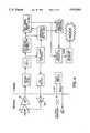
- FIG. 1is a schematic block diagram which illustrates a compact millimeter wave radar sensor in accordance with the present invention
- FIG. 2ais a block diagram which illustrates a monolithic millimeter wave integrated circuit (MMIC) transceiver
- FIG. 2bis a block diagram which illustrates an alternate embodiment of a monolithic millimeter wave integrated circuit (MMIC) transceiver;
- MMICmillimeter wave integrated circuit
- FIG. 3is a schematic diagram which illustrates a millimeter wave band microstrip patch antenna design example
- FIG. 4is a block diagram which illustrates the major functions of a digital signal processor in accordance with the present invention
- FIGS. 5(a-d)are assembly views of a compact radar sensor module example
- FIG. 6is an assembly view of a compact packaging system for a radar system according to the present invention.
- FIG. 7is a view of a radar circuit fabricated on a bottom surface of a dielectric substrate
- FIG. 8is a top view of the radar system of FIG. 6 after assembly
- FIG. 9is an end view of the assembled radar system of FIG. 8;
- FIG. 10ais a top view of a slot radiator according to the prior art
- FIG. 10bis a side view of the slot radiator of FIG. 10a;
- FIG. 11ais a top view of a slot radiator including a reflector ground plane according to the prior art
- FIG. 11bis a side view of the slot radiator with the reflector ground plane of FIG. 11a;
- FIG. 12ais a top view of a slot-coupled patch radiator according to the prior art
- FIG. 12bis a side view of the slot-coupled patch radiator of FIG. 12a;
- FIG. 13ais a top view of a slot-coupled radiator incorporating a frequency selective surface according to the present invention.
- FIG. 13bis a side view of the slot-coupled radiator incorporating a frequency selective surface of FIG. 13a;
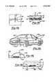
- FIG. 14ais a perspective view of a vehicle incorporating the radar system of FIG. 6 in a side view mirror and tail light assembly;
- FIG. 14bis a top view of the side view mirror of FIG. 14a ;
- FIG. 14cis a top view of the tail light assemble of FIG. 14a.
- FIG. 1a schematic block diagram is shown therein which illustrates a compact millimeter wave (MMW) radar sensor 10 in accordance with the present invention.
- Radar sensor 10employs a monolithic millimeter wave integrated circuit (MMIC) transceiver 12.
- MMICmillimeter wave integrated circuit
- Transceiver 12provides MMW transmit and receive functions which are integrated onto a single monolithic chip 13 using standard photolithographic techniques known in the art.
- Transceiver 12includes a voltage controlled oscillator (VCO) 20 which is connected to an amplifier 22.
- Amplifier 22is further connected to a coupler 25 which is connected to port A of duplexer 24.
- a pre-amplifier 28is connected to port B of duplexer 24 for amplifying a reflected signal received by antenna 14.
- VCOvoltage controlled oscillator
- a balanced mixer 26is provided which has an input connected to the output of pre-amplifier 28.
- Balanced mixer 26is further adapted to receive a leakage signal which is the result of the coupler 25 output of the transmitted signal generated by the voltage controlled oscillator 20 and the transmit amplifier 22.
- Balanced mixer 26is adapted to provide the difference between the transmit signal and the reflected signal.
- the output of balanced mixer 26is an intermediate frequency (IF) known as the beat frequency which contains the range information.
- IFintermediate frequency
- duplexer 24 and coupler 25may be removed and replaced with a simple coupler to allow for further cost savings and smaller size.
- An antenna 14is connected to port C of duplexer 24.
- the antenna 14can be a microstrip patch antenna. Other antenna configurations will be readily apparent to those skilled in the art.
- the antenna 14is adapted to transmit a high frequency modulated carrier signal throughout a desired field to be monitored. This transmitted signal may have a frequency of around 35 to 94 GHz. Higher frequency signal may also be employed.
- Antenna 14is further adapted to receive a reflected signal which is the result of the transmitted signal reflecting off of objects located within the field.
- An IF pre-amplifier 30is connected to the output of the balanced mixer 26 for amplifying the IF output signal therefrom.
- an automatic gain control amplifier 32Connected to the output of IF pre-amplifier amplifier 30 is an automatic gain control amplifier 32 which provides high dynamic range.
- An analog-to-digital converter 34is connected to the output of the automatic gain control amplifier 32 for receiving a signal therefrom.
- the analog-to-digital converter 34is further adapted to receive a clock signal from clock 37 of digital signal processor 16 and provide a digital output to the digital signal processor 16.
- Analog-to-digital converter 34is a standard off-the-shelf 8-bit converter and is capable of handling IF signals and providing a dynamic range of about 48 dB.
- a digital-to-analog converter 36is further connected to digital signal processor 16 for receiving an input signal therefrom.
- the digital-to-analog converter 36is adapted to provide a gain control signal to the automatic gain control amplifier 32 which provides a dynamic range of about 50 dB.
- the automatic gain control amplifier 32in combination with the analog-to-digital converter 34, the digital signal processor 16, and the digital-to-analog converter 36 make up a dynamic range adjustment control loop 35. Control loop 35 provides for the dynamic range required to process the variations in target reflections and the range of distance desired.
- An FM modulator 40is connected to digital signal processor 16 for receiving a square wave signal therefrom.
- FM modulator 40is configured for providing a triangular modulation waveform signal at the same periodicity as the square waveform.
- the output of FM modulator 40is connected to the input of the voltage controlled oscillator 20 of transceiver 12 for providing the frequency modulated signal thereto.
- Digital signal processor 16is further connected to an external interface 42. External interface 42 provides connection to an output display 44 and input terminals 46. Digital signal processor 16 is manufactured by AT&T and has a model number DSP16. Other suitable digital signal processors such as a Motorola 56001 and Texas Instruments TMS320C15 may also be used. Digital signal processor 16 performs all the necessary processing and embedded intelligence functions therein. Processor 16 includes processing capabilities for providing digital filtering, integrations and various other processing functions. In essence, digital signal processor 16 is adapted to provide control signals and detect any reflected signal from objects within the field being monitored and provide output responses therefrom. From the frequency shift and other information, the digital signal processor 16 provides the distance information.
- a compact voltage regulator 47provides the +5 v dc supply from a 12 v dc supply.
- Another compact voltage regulator 48provides the +10 v dc supply from the 12 v dc supply.
- different voltage regulatorsmay be used to provide the +5 v and +10 v dc from other voltage sources.
- FIG. 2ais a block diagram which illustrates one embodiment of the monolithic millimeter wave integrated circuit (MMIC) transceiver 12.
- Transceiver 12includes a voltage-controlled oscillator (VCO) 20 adapted to receive the FM modulation signal from FM modulator 40 and provide a frequency modulated carrier signal therefrom.
- Voltage controlled oscillator 20includes a single high electron mobility transistor (HEMT) and an associated tank circuit for providing the carrier signal.
- the voltage controlled oscillator 20is modulated by applying a voltage to a varactor located in an oscillator tank circuit.
- Connected to the output of the voltage controlled oscillator 20is a two-stage amplifier 22 having a first amplifier stage 21 and second amplifier stage 23.
- Amplifier 22amplifies the signal which is then transmitted to the antenna 14 through the duplexer 24 and the coupler 25.
- the output of amplifier 22is connected to port D of the coupler 25.
- the port E of the coupler 25is connected to the port A of the duplexer 24.
- the transmit output to the antenna 14is through port C of the duplexer 24.
- the combination of voltage controlled oscillator 20 in connection with the amplifier 22forms a transmitter 50.
- Transceiver 12further includes a two-stage pre-amplifier 28 having a first stage 29 and second stage 27.
- Pre-amplifier 28is adapted to receive and amplify the reflected signals gathered by the antenna 14.
- the balanced mixer 26is connected to the output of the pre-amplifier 28. Together, balanced mixer 26 and the pre-amplifier 28 form the receiver 52.
- the duplexer 24 and the coupler 25form a network for isolating the transmitter 50 from the receiver 52.
- the couplerprovides the reference transmit signal path to the balanced mixer 26 of the receiver 52 and the transmit path to the duplexer 24 and antenna 14.
- the balanced mixer 26provides the difference between the reference signal and the reflected signal to obtain an intermediate frequency (IF) known as the beat frequency.
- IFintermediate frequency
- the duplexer 24 and the coupler 25 of the original implementation as shown in FIG. 2aare replaced with a simple coupler 31 to allow for further cost savings and smaller size of the MMIC transceiver.
- the voltage controlled oscillator 20 and the two-stage transmit amplifier 21 and 23are basically the same as in the original transmitter except in chip layout.
- the two-stage amplifier 27 and 29, and the balanced mixer 26are similar to the original embodiment, except in chip layout and in that the balanced mixer 26 is further adapted to receive a leakage transmit signal which is used as the reference signal.
- the leakage signalis the result of the signal generated by the voltage controlled oscillator 20 being transmitted across a leakage path 39 from amplifier 23 to amplifier 29 across the new coupler 31.
- This alternate embodiment of the MMIC transceiveradvantageously utilizes this leakage signal while providing isolation between the transmitter 50 and the receiver 52.
- FIG. 3illustrates the antenna 14 designed as a millimeter wave band microstrip patch antenna.
- a plurality of radiating/receiving microstrip patches 54are provided in a 4 ⁇ 4 array. In alternate embodiments, a 4 ⁇ 2 and a 4 ⁇ 1 array may also be used.
- Microstrip patches 54are connected by microstrip feedlines 56.
- the antenna 14is adapted to be etched on a printed circuit board and may be adapted to provide for a plurality of such microstrip patches 54 in various array designs.
- the array designessentially determines the beam shape which may be adapted to provide for various coverage requirements for different applications.
- the resulting antenna 14is small and planar, and has a patch pattern that can easily be changed to adapt to various applications and mounting requirements.
- the planar antennaenables incorporation of the radar sensor in the tail light assembly, side mirror assembly, or rear bumper of a vehicle.
- the particular antenna design example shown thereinprovides for an overall size which is less than 1.5 inches by 1.5 inches. However, various shapes and sizes may be used, depending on the particular application.
- FIG. 4is a block diagram which illustrates the major functions of the digital signal processor 16.
- the signal processing functions performed by the digital signal processor 16include digital filtering and integration to remove clutter, reduce false alarms and to increase sensitivity.
- the embedded intelligence functionsinclude decision logic, control, display, annunciation control, and self testing.
- the digital signal processor 16performs these functions in firmware to achieve the lowest possible recurring costs.
- the firmwaremay include software such as machine code fabricated in read-only memory (ROM).
- the digital signal processor 16reads the digitized data from the analog-to-digital converter 34 and calculates the gain control that is to be applied to the automatic gain control amplifier 32.
- the firmware of digital signal processor 16reads in a complete sweep of the radar data and captures the data at a sampling rate of about 2.5 megahertz.
- the digital signal processor 16calculates a fast Fourier transform (FFT).
- FFTfast Fourier transform
- the total energyis estimated from the FFT calculation and used to calculate the gain control signal which is applied to automatic gain control amplifier 32.
- the transformed datais further divided into range bins in order to detect valid returns. Several sweeps are transformed and accumulated, resulting in a 6 dB processing gain in the signal-to-noise ratio of the received signal.
- the digital signal processor 16then weighs the spectrum to reduce the effects of clutter.
- a threshold decision functionis applied to the range bins to detect valid returns. These returns are then compared to several past decisions from previous sweeps.
- the digital signal processor 16By comparing past returns, the digital signal processor 16 adapts the decision thresholds and clutter weighing functions as the environment changes in order to increase differentiation of valid returns and reject disturbances and spurious returns. The digital signal processor 16 furthermore determines the closest valid return. Finally a periodically updated display provides the decision.
- FIG. 5illustrates the packaging design for a particular radar sensor example of this invention.
- a radar sensor module 60is shown having a housing subassembly 62, a radome/cover 64 and an electronic subassembly having a support plate (not shown) and two printed circuit board assemblies 66 and 68.
- One of the printed circuit board assemblies 68is laminated to the top of the support plate and has the patch antenna assembly etched thereon and the MMIC transceiver along with the preamplifier circuit.
- This assemblyis connected by flexible jumper cable to the other multi-layer digital printed circuit board assembly 66 that is mounted to the rear portion of the support plate.
- This second printed circuit board assembly 66has components mounted on both sides to minimize the module size.
- the radome/cover 64is bonded over the top of the module 60 and provides impact protection as well as a moisture seal for the entire module 60.
- the invention discussed hereinis not restricted to this particular module design, for different applications may require variations thereof.
- a compact built-in packaging system for a radar system 100includes a lower electronics housing 104 with an integral connector 106. While the lower housing 104 in FIG. 6 is rectangular in shape, other shapes are contemplated.
- a dielectric substrate 108includes a radar circuit 110 mounted on a bottom surface 112 thereof (see FIG. 7).
- a ground plane 114is formed on a top surface 115 of the dielectric substrate 108. Slots 116 and 117 in the ground plane 114 transmit and receive electromagnetic energy as will be described further below.
- the lower housing 104positions and supports a digital signal processing circuit (DSPC) 118.
- the DSPC 118can be the DSPC disclosed in conjunction with FIGS. 1-5, or a conventional DSPC can be used.
- a frame 119 including transmit and receive openings 120 and 121is positioned over the dielectric substrate 108 to provide uniform spacing between the dielectric substrate 108 and a frequency selective surface (FSS) 122, described further below.
- a spacer 123 including transmit and receive openings 124 and 125is positioned on an upper surface of the FSS 122.
- a radome 126protects the radar system 100 from harmful effects of the environmental conditions in which the radar system 100 is operated (e.g., rain, dust, mud, etc.) without noticeably affecting the performance of the radar system 100.
- the radome 126can be made from a variety of materials. Transmission data for multiple materials through which the radar system 100 radiates and receives the transmit and reflected signals is illustrated in Table A (set forth below). "Transmission” refers to the percent of the transmitted signal which is radiated without absorption by the material. As can be seen from Table A, many different materials can be effectively utilized.
- the radar circuit 110 located on the bottom surface of the substrate 108can include a MMIC transceiver 132, microstrip feedlines 134 and 136 connected to slots 116 and 117, and an IF/modulator circuit (IF/MC) 138 described in detail above in conjunction with FIGS. 1-5.
- a rectangular spacer 139can be used to position the substrate 108 with respect to the DSPC 118, although other means for spacing are contemplated.
- Fasteners 140connect the lower housing 104, the DSPC 118, the dielectric substrate 108, the frame 119, the FSS 122, the spacer 123, and the radome 126 into a compact integral unit.
- the radome 126can be attached to the spacer 123.
- the radome 126can include a plurality of holes for receiving the fasteners 140, or the spacer 123 can be formed integrally with the radome 126.
- the dielectric substrate 108, the frame 119, and the lower housing unit 104enclose the radar circuit 110 and the DSPC 118 in a hermetically sealed environment.
- the FSS 122is a perforated plate made of metal or metal-coated plastic.
- the FSS 122includes a transmit aperture 146 and a receive aperture 148 each including a plurality of uniformly spaced holes 150.
- the FSS 122is positioned above the substrate 108. Slots 116 and 117 which are fed by the microstrip feedlines 134 and 136 transmit and receive electromagnetic energy.
- the microstrip feedlines 134 and 136, the slots 116 and 117 formed in the ground plane 114, the frame 119, the dielectric substrate 108, and the FSS 122form an integral antenna 144 for the radar system 100 while also forming part of an enclosure for the radar system 100.
- Both the IF/MC 138 and the microstrip feedlines 134 and 136are fabricated on the bottom surface 112 of the substrate 108 which can be made of Alumina or Quartz.
- the ground plane 114fabricated on the top surface 115 of the substrate 108 using metal, for example copper or gold.
- FIGS. 10, 11 and 12illustrate several prior art antenna radiation configurations.
- FIG. 10ais a top view of and FIG. 10b is a side view of a slot radiator antenna 200 including a microstrip feedline 204 formed on a bottom surface 206 of a dielectric substrate 208.
- a ground plane 210 formed on a top surface 212 of the dielectric substrate 208includes a slot 214 which radiates into an upper half-space (+Z direction) above the ground plane 210 and into a lower half-space (-Z direction) below the ground plane 210. It is desirable to maximize electromagnetic radiation in one direction in the Z plane (typically away from radar electronics) while minimizing electromagnetic radiation in an opposite direction in the Z plane, e.g. Where a radar or other circuits may be located.
- Two configurationsare offered by conventional antenna designs for obtaining maximum radiation in one direction in the +Z plane while minimizing radiation in the opposite direction in the -Z plane including a reflector ground plane configuration 230 illustrated in FIG. 11, and a slot-coupled patch configuration 232 illustrated in FIG. 12.
- the reflector ground plane configuration 230 in FIGS. 11a and 11bincludes a reflecting ground plane 234 which reflects radiation in the -Z direction 180 degrees, in other words, in the +Z direction. If the ground plane 210 is spaced a distance "D" (which is approximately one quarter wavelength) from the reflecting ground plane 234, the reflected electromagnetic radiation from the reflecting ground plane 234 in the +Z direction is in phase with radiation emitted in the +Z direction by the ground plane 210.
- Dwhich is approximately one quarter wavelength
- the reflector ground plane configuration 230cannot be effectively used with the integrated radar sensor 100 of the present invention.
- electromagnetic fields traveling between the ground plane 210 and the reflecting ground plane 234adversely affect electronics located therebetween, for example the IF/MC 138, the DSPC 118, the microstrip feedline 134, etc.
- the space "D" between the reflecting ground plane 234 and the ground plane 210may be insufficient to accommodate the electronics located therebetween.
- the conventional slot-coupled patch configuration 232 in FIGS. 12a and 12bincludes a microstrip feedline 252 etched on a bottom surface 254 of a first dielectric substrate 256.
- a ground plane 258 having a slot 260 formed thereinis fabricated on a top surface 262 of the first dielectric substrate 256.
- a bottom surface 264 of a second dielectric substrate 266is in contact with the ground plane 258.
- a patch 268is fabricated on a top surface 270 of the second dielectric substrate 266 and is designed to match impedance in the +Z direction to an impedance of the microstrip feedline 252 to obtain maximum electromagnetic energy transfer. In other words, the patch 268 creates a condition favoring flow of electromagnetic energy in the +Z direction.
- a length of the slot 260is typically less than a resonant length to further reduce electromagnetic radiation in -Z direction.
- the slot-coupled patch configuration 232cannot be effectively used with the integrated radar sensor 100 of the present invention.
- the slot-coupled patch configuration 232has low efficiency due to high material loss at microwave frequencies.
- the slot-coupled coupled patch on figuration 232has a less rigid structure due to the first and second dielectric substrates 256 and 66 which are typically thin.
- FIGS. 13a and 13billustrate the integral antenna 144 of the present invention in detail.
- the microstrip feedline 134is etched on the bottom surface 112 of the dielectric substrate 108.
- the ground plane 114is fabricated on the top surface 115 and includes the slots 116 and 117 (not shown in FIGS. 13a and 13b) formed therein.
- the FSS 122is spaced (by the frame 123) above the ground plane 114 with air, acting as a dielectric, located therebetween.
- the FSS 122differs from conventional frequency selective surfaces.
- frequency selective surfacesinclude cross dipole (or Jerusalem cross, tripole, dipole, rectangular, circular disk) arrays etched on a dielectric substrate.
- metalsuch as copper is deposited or printed on the dielectric substrate in the particular shape chosen.
- Traditional frequency selective surface designshave been the subject of extensive study, for example see Agrawal & Imbriale, "Design of a Dichroic Subreflector", IEEE, Transactions On Antennas and Propagation, Vol. AP-27, No. 4, July 1979; Chen, Ingerson & Chen, "The Design of Wideband Sharp Cut-off Dichroic", IEEE Antennas and Propagation Symposium, Vol. 2, p.
- the FSS 122 of the present inventionis fabricated using a metal plate with holes 150 which can be in the shape of a cross, Jerusalem cross, tripole, dipole, rectangle or circle. Other shapes will be readily apparent.
- the radiation patterns and impedances for each of the shapesare known, for example, the impedance and radiation patterns of the conventional cross and Jerusalem cross (see FIG. 8b) formed on a dielectric substrate are discussed in the above incorporated references.
- the radiation patterns for the FSS 122 according to the inventioncan be derived. Babinet's principle is discussed in C. Balanis "Antenna Theory: Analysis & Design", page 497; T. Kong “Electromagnetic Wave Theory", page 366; and T. Milligan "Modern Antenna Design", page 70. All of the above are incorporated by reference.
- the FSS 122 of the present inventionis a complementary radiating structure to the conventional cross and Jerusalem cross radiators.
- the FSS 122is a complimentary structure because when the FSS 122 is combined with the conventional cross (or other shape), a solid screen with no overlaps is formed. Extension of these principles to other shapes will be readily apparent.
- the impedance, and the magnetic and electric fields of the FSS 122can also be predicted from the impedance, and the magnetic and electric fields of the conventional cross (or other shape).
- the magnetic field of the conventional cross radiator (or other shape)is related to the electric field of the complimentary FSS 122.
- the electric field of the conventional cross (or other shape) radiatoris related to the magnetic field of the FSS 122.
- the impedances of the conventional cross (or other shape) radiator and the FSS 122are related to the intrinsic impedance of a medium in which the conventional radiating structure and the FSS 122 are located.
- the impedance provided by the FSS 122is also related to the distance between the FSS 122 and the ground plane 114.
- the FSS 122matches the impedance of the upper half-space (e.g. in the +Z direction) to the impedance of the microstrip feedlines 134 and 136 with significantly higher efficiency than the patch antenna 232. Since the FSS 122 is made of metal or metal-coated plastic, the integral antenna 144 is more rigid and durable than conventional designs thus improving the packaging of the radar system 100.
- the vehicle 300includes a side view mirror 304 attached to a side door 305 or other component of the vehicle 300.
- the side view mirror 304includes an outer housing 306 and a mechanism (not shown) for supporting and positioning a mirror 308.
- a windowis cut from the mirror 308, and the radar system 100 is attached in the window.
- the radar system 100can be mounted to a rear surface 310 of the mirror 308.
- the radar system 100can be incorporated into a rear tail light assembly 320 of the vehicle 300.
- the rear tail light assembly 320can include a bulb assembly 322 which illuminates through a cover 324 which can be made of plastic.
- the radar system 100can be mounted on an inside surface 330 of the cover 324 of the rear tail light assembly 320, and can radiate and receive the transmit and receive signals through the cover 324 which serves as an integrated radome to replace radome 126.
- the cover 324should have electromagnetic properties allowing flow of electromagnetic radiation flow therethrough.
- a windowcan be cut from the cover 324 allowing electromagnetic radiation to directly impinge upon the radome 126 of the radar system 100.
- the radar system 100 mounted on the vehicle 300can be used in intelligent cruise control systems, collision avoidance systems, predictive crash systems, lane change systems, back-up warning systems, vision enhancement systems, ground speed measuring systems, ground height measuring systems, etc.
- the radar system 100is described above in conjunction with the vehicle 300 such as an automobile, other applications will be readily apparent.
- the radar systemcan be used in police radar system or in perimeter surveillance systems.
- the radar systemcan also be used as a phased array antenna for communications systems and other radar applications.
Landscapes
- Engineering & Computer Science (AREA)
- Radar, Positioning & Navigation (AREA)
- Remote Sensing (AREA)
- Physics & Mathematics (AREA)
- Computer Networks & Wireless Communication (AREA)
- General Physics & Mathematics (AREA)
- Computer Security & Cryptography (AREA)
- Electromagnetism (AREA)
- Signal Processing (AREA)
- Radar Systems Or Details Thereof (AREA)
Abstract
Description
TABLE A______________________________________ Thickness FreqMaterial (mil) (GHz) Transmission______________________________________Mylar 5 35 99.5 140 95.0Teflon 60 35 92.0 140 95.0Lexan 55 35 72.0 140 81.0Lexan 55 35 68.0(coated) 140 80.0Plexiglass 375 35 60.0 140 60.0Plexiglass 250 140 70.0Polyethylene 5 35 99.0 140 100.0______________________________________
Claims (36)
Priority Applications (5)
| Application Number | Priority Date | Filing Date | Title |
|---|---|---|---|
| US08/117,266US5512901A (en) | 1991-09-30 | 1993-09-07 | Built-in radiation structure for a millimeter wave radar sensor |
| US08/173,540US5508706A (en) | 1991-09-30 | 1993-12-23 | Radar signal processor |
| JP5334109AJP2670422B2 (en) | 1993-09-07 | 1993-12-28 | Built-in radiating structure for millimeter-wave radar sensor |
| DE69327162TDE69327162T2 (en) | 1993-09-07 | 1993-12-30 | Built-in radiator structure for a millimeter wave radar sensor |
| EP93310625AEP0642190B1 (en) | 1993-09-07 | 1993-12-30 | Built-in radiation structure for a millimeter wave radar sensor |
Applications Claiming Priority (2)
| Application Number | Priority Date | Filing Date | Title |
|---|---|---|---|
| US07/767,953US5315303A (en) | 1991-09-30 | 1991-09-30 | Compact, flexible and integrated millimeter wave radar sensor |
| US08/117,266US5512901A (en) | 1991-09-30 | 1993-09-07 | Built-in radiation structure for a millimeter wave radar sensor |
Related Parent Applications (1)
| Application Number | Title | Priority Date | Filing Date |
|---|---|---|---|
| US07/767,953Continuation-In-PartUS5315303A (en) | 1991-09-30 | 1991-09-30 | Compact, flexible and integrated millimeter wave radar sensor |
Related Child Applications (1)
| Application Number | Title | Priority Date | Filing Date |
|---|---|---|---|
| US08/173,540Continuation-In-PartUS5508706A (en) | 1991-09-30 | 1993-12-23 | Radar signal processor |
Publications (1)
| Publication Number | Publication Date |
|---|---|
| US5512901Atrue US5512901A (en) | 1996-04-30 |
Family
ID=22371907
Family Applications (1)
| Application Number | Title | Priority Date | Filing Date |
|---|---|---|---|
| US08/117,266Expired - LifetimeUS5512901A (en) | 1991-09-30 | 1993-09-07 | Built-in radiation structure for a millimeter wave radar sensor |
Country Status (4)
| Country | Link |
|---|---|
| US (1) | US5512901A (en) |
| EP (1) | EP0642190B1 (en) |
| JP (1) | JP2670422B2 (en) |
| DE (1) | DE69327162T2 (en) |
Cited By (57)
| Publication number | Priority date | Publication date | Assignee | Title |
|---|---|---|---|---|
| US5600325A (en)* | 1995-06-07 | 1997-02-04 | Hughes Electronics | Ferro-electric frequency selective surface radome |
| US5617098A (en)* | 1994-11-10 | 1997-04-01 | Honda Giken Kogyo Kabushiki Kaisha | Multichannel radar system for motor vehicles |
| US5712640A (en)* | 1994-11-28 | 1998-01-27 | Honda Giken Kogyo Kabushiki Kaisha | Radar module for radar system on motor vehicle |
| US5959570A (en)* | 1997-11-21 | 1999-09-28 | Raytheon Company | Automotive forward looking sensor blockage detection system and related techniques |
| US5982329A (en)* | 1998-09-08 | 1999-11-09 | The United States Of America As Represented By The Secretary Of The Army | Single channel transceiver with polarization diversity |
| US6107955A (en)* | 1997-05-10 | 2000-08-22 | Robert Bosch Gmbh | Radar sensor for a vehicle |
| US6107956A (en)* | 1997-11-21 | 2000-08-22 | Raytheon Company | Automotive forward looking sensor architecture |
| US6166698A (en)* | 1999-02-16 | 2000-12-26 | Gentex Corporation | Rearview mirror with integrated microwave receiver |
| US6215389B1 (en) | 1999-04-14 | 2001-04-10 | Gentex Corporation | Time-independent, event-based system for receiving and discriminating unique codes from multiple transmitters and method for doing the same |
| US6232910B1 (en) | 1998-02-20 | 2001-05-15 | Amerigon, Inc. | High performance vehicle radar system |
| US6253068B1 (en)* | 1997-05-09 | 2001-06-26 | Micrel, Incorporated | Fully integrated all-CMOS AM transmitter with automatic antenna tuning |
| US6329949B1 (en)* | 2000-03-09 | 2001-12-11 | Avaya Technology Corp. | Transceiver stacked assembly |
| US6335680B1 (en)* | 2000-09-28 | 2002-01-01 | Mitsubishi Denki Kabushiki Kaisha | Vehicle surroundings monitoring device |
| US6380883B1 (en)* | 1998-02-23 | 2002-04-30 | Amerigon | High performance vehicle radar system |
| US6396446B1 (en) | 1999-02-16 | 2002-05-28 | Gentex Corporation | Microwave antenna for use in a vehicle |
| US6400308B1 (en) | 1998-02-20 | 2002-06-04 | Amerigon Inc. | High performance vehicle radar system |
| US6400835B1 (en)* | 1996-05-15 | 2002-06-04 | Jerome H. Lemelson | Taillight mounted vehicle security system employing facial recognition using a reflected image |
| US6411250B1 (en)* | 1997-09-01 | 2002-06-25 | Cambridge Consultants Limited | Electromagnetic sensor system |
| WO2002054448A3 (en)* | 2000-12-28 | 2002-08-08 | Lockheed Corp | Low cost mmw transceiver packaging |
| US20020126057A1 (en)* | 2000-07-18 | 2002-09-12 | King Patrick F. | Wireless communication device and method |
| US6452533B1 (en)* | 1999-11-16 | 2002-09-17 | Mitsubishi Denki Kabushiki Kaisha | Vehicle periphery monitoring device |
| US20020175873A1 (en)* | 2000-07-18 | 2002-11-28 | King Patrick F. | Grounded antenna for a wireless communication device and method |
| US20020175818A1 (en)* | 2000-07-18 | 2002-11-28 | King Patrick F. | Wireless communication device and method for discs |
| US20030095062A1 (en)* | 2001-11-19 | 2003-05-22 | Hitachi, Ltd. | Vehicle-onboard signal processing device and vehicle-onboard radar system |
| US6600103B1 (en)* | 1999-01-28 | 2003-07-29 | Robert Bosch Gmbh | Housing for an electronic device in microwave technology |
| US6611227B1 (en) | 2002-08-08 | 2003-08-26 | Raytheon Company | Automotive side object detection sensor blockage detection system and related techniques |
| US6696935B2 (en) | 2001-09-10 | 2004-02-24 | Gentex Corporation | Tire monitoring system |
| US20040078957A1 (en)* | 2002-04-24 | 2004-04-29 | Forster Ian J. | Manufacturing method for a wireless communication device and manufacturing apparatus |
| US20040100418A1 (en)* | 2002-11-22 | 2004-05-27 | Best Timothy E. | Complementary dual antenna system |
| US6861942B1 (en) | 1999-07-21 | 2005-03-01 | Gentex Corporation | Directionally-adjustable antenna system using an outside mirror for automotive applications |
| US20050105075A1 (en)* | 2002-08-17 | 2005-05-19 | Frank Gottwald | Device for detecting and evaluating objects in the surroundings of a vehicle |
| US20060132350A1 (en)* | 2004-12-16 | 2006-06-22 | Boltovets Nikolai S | Short-range automotive radar transceiver |
| US7401059B1 (en)* | 1999-11-08 | 2008-07-15 | Aloft Media, Llc | System, method and computer program product for a collaborative decision platform |
| US20090135043A1 (en)* | 2004-12-30 | 2009-05-28 | Leblanc Stephen P | Vehicle Radar Sensor Assembly |
| US20090243912A1 (en)* | 2008-03-31 | 2009-10-01 | Lohmeier Stephen P | Automotive Radar Sensor Blockage Detection System and Related Techniques |
| US20090251356A1 (en)* | 2008-04-04 | 2009-10-08 | Toyota Motor Engineering & Manufacturing North America, Inc. | Dual-band antenna array and rf front-end for automotive radars |
| US20090251357A1 (en)* | 2008-04-04 | 2009-10-08 | Toyota Motor Engineering & Manufacturing North America, Inc. | Dual-band antenna array and rf front-end for mm-wave imager and radar |
| US20090251362A1 (en)* | 2008-04-04 | 2009-10-08 | Alexandros Margomenos | Three dimensional integrated automotive radars and methods of manufacturing the same |
| US20100182107A1 (en)* | 2009-01-16 | 2010-07-22 | Toyota Motor Engineering & Manufacturing North America,Inc. | System and method for improving performance of coplanar waveguide bends at mm-wave frequencies |
| US20140028529A1 (en)* | 2012-07-25 | 2014-01-30 | Nokia Siemens Networks Oy | Variable adaption of active antenna system radio frequency signal filtering |
| US8786496B2 (en) | 2010-07-28 | 2014-07-22 | Toyota Motor Engineering & Manufacturing North America, Inc. | Three-dimensional array antenna on a substrate with enhanced backlobe suppression for mm-wave automotive applications |
| DE10161340B4 (en)* | 2001-05-24 | 2014-07-31 | Mitsubishi Denki K.K. | Vehicle environment monitoring device |
| WO2014202318A1 (en)* | 2013-06-20 | 2014-12-24 | Siemens Aktiengesellschaft | Antenna module, and device comprising antenna module |
| US20150035703A1 (en)* | 2012-02-10 | 2015-02-05 | Robert Bosch Gmbh | Radar sensor device having an adjusting mirror |
| US20150097720A1 (en)* | 2013-10-08 | 2015-04-09 | Robert Bosch Gmbh | High-frequency circuit having crossed lines |
| US20150109162A1 (en)* | 2013-10-17 | 2015-04-23 | Robert Bosch Gmbh | Combination of radar sensor and trim component for a motor vehicle |
| US20150210312A1 (en)* | 2014-01-30 | 2015-07-30 | Mobileye Vision Technologies Ltd. | Systems and methods for detecting low-height objects in a roadway |
| WO2016025136A1 (en)* | 2014-08-14 | 2016-02-18 | Google Inc. | Modular planar multi-sector 90 degrees fov radar antenna architecture |
| US9612317B2 (en) | 2014-08-17 | 2017-04-04 | Google Inc. | Beam forming network for feeding short wall slotted waveguide arrays |
| US9653796B2 (en) | 2013-12-16 | 2017-05-16 | Valeo Radar Systems, Inc. | Structure and technique for antenna decoupling in a vehicle mounted sensor |
| US9711870B2 (en) | 2014-08-06 | 2017-07-18 | Waymo Llc | Folded radiation slots for short wall waveguide radiation |
| US20170237148A1 (en)* | 2016-02-16 | 2017-08-17 | GM Global Technology Operations LLC | Impedance surface treatment for mitigating surface waves and improving gain of antennas on glass |
| US10739437B2 (en)* | 2015-01-26 | 2020-08-11 | Nec Corporation | Frequency selective surface, wireless communication device, and radar device |
| CN112363127A (en)* | 2020-10-26 | 2021-02-12 | 北京环境特性研究所 | Radar reflector |
| US11187780B2 (en)* | 2018-04-19 | 2021-11-30 | Honda Motor Co., Ltd. | Transportation apparatus |
| US20210373152A1 (en)* | 2020-05-28 | 2021-12-02 | Hyundai Mobis Co., Ltd. | Radar device |
| US11350239B2 (en)* | 2019-07-17 | 2022-05-31 | Ford Global Technologies, Llc | Smart mmWave c-V2X antenna |
Families Citing this family (54)
| Publication number | Priority date | Publication date | Assignee | Title |
|---|---|---|---|---|
| BR9507694A (en)* | 1994-05-23 | 1997-09-23 | Minnesota Mining & Mfg | Modular microtape antenna systems and integrated retro-reflective modular electronic signal |
| GB2337861B (en)* | 1995-06-02 | 2000-02-23 | Dsc Communications | Integrated directional antenna |
| DE19535962C1 (en)* | 1995-09-27 | 1997-02-13 | Siemens Ag | Doppler radar module |
| FR2741958B1 (en)* | 1995-12-04 | 1998-01-30 | Aerospatiale | RADIOALTIMETER PROTECTED AGAINST VARIOUS DETECTION |
| JPH1079616A (en)* | 1996-09-03 | 1998-03-24 | Hino Motors Ltd | On-vehicle radar antenna |
| DE19715998A1 (en)* | 1997-04-17 | 1998-10-22 | Daimler Benz Ag | Motor vehicle radar arrangement |
| DE19719953B4 (en)* | 1997-05-14 | 2008-09-11 | Robert Bosch Gmbh | Automotive radar sensor |
| EP0929115A1 (en)* | 1998-01-09 | 1999-07-14 | Nokia Mobile Phones Ltd. | Antenna for mobile communications device |
| US5929813A (en)* | 1998-01-09 | 1999-07-27 | Nokia Mobile Phones Limited | Antenna for mobile communications device |
| JPH11248835A (en)* | 1998-02-27 | 1999-09-17 | Mitsubishi Electric Corp | Radio radar equipment |
| JP2000299199A (en)* | 1999-04-13 | 2000-10-24 | Plasma System Corp | Plasma generating device and plasma processing device |
| US6140970A (en)* | 1999-04-30 | 2000-10-31 | Nokia Mobile Phones Limited | Radio antenna |
| DE19961387B4 (en)* | 1999-12-20 | 2006-02-23 | Siemens Ag | radar sensor |
| DE10012116A1 (en)* | 2000-03-13 | 2001-09-27 | Agta Record Ag Fehraltorf | Motion detection and monitoring sensor device for automatic door installation, includes flat emitters formed in matrix array on substrate, forming patch antenna |
| JP3573683B2 (en) | 2000-05-15 | 2004-10-06 | 株式会社日立製作所 | In-vehicle radio radar system |
| DE10042105B4 (en)* | 2000-07-12 | 2010-09-02 | Volkswagen Ag | Method for adjusting a directional antenna of a radar system |
| DE10036131A1 (en)* | 2000-07-25 | 2002-02-07 | Volkswagen Ag | Radar sensor for detecting the traffic situation in the environment of a motor vehicle |
| US6489927B2 (en) | 2000-08-16 | 2002-12-03 | Raytheon Company | System and technique for mounting a radar system on a vehicle |
| US6501415B1 (en) | 2000-08-16 | 2002-12-31 | Raytheon Company | Highly integrated single substrate MMW multi-beam sensor |
| US6657581B1 (en) | 2000-08-16 | 2003-12-02 | Raytheon Company | Automotive lane changing aid indicator |
| JP2004506906A (en) | 2000-08-16 | 2004-03-04 | レイセオン・カンパニー | Automotive radar system and method |
| US6707419B2 (en) | 2000-08-16 | 2004-03-16 | Raytheon Company | Radar transmitter circuitry and techniques |
| JP2004505844A (en) | 2000-08-16 | 2004-02-26 | レイセオン・カンパニー | Safe distance algorithm for adaptive cruise control |
| JP5063851B2 (en) | 2000-08-16 | 2012-10-31 | ヴァレオ・レイダー・システムズ・インコーポレーテッド | Proximity object detection system |
| JP4928052B2 (en)* | 2000-08-16 | 2012-05-09 | ヴァレオ・レイダー・システムズ・インコーポレーテッド | Switched beam antenna architecture |
| KR100776868B1 (en) | 2000-08-16 | 2007-11-16 | 레이던 컴퍼니 | Video Amplifiers for Radar Receivers |
| US6675094B2 (en) | 2000-09-08 | 2004-01-06 | Raytheon Company | Path prediction system and method |
| US6708100B2 (en) | 2001-03-14 | 2004-03-16 | Raytheon Company | Safe distance algorithm for adaptive cruise control |
| US6970142B1 (en) | 2001-08-16 | 2005-11-29 | Raytheon Company | Antenna configurations for reduced radar complexity |
| US6995730B2 (en) | 2001-08-16 | 2006-02-07 | Raytheon Company | Antenna configurations for reduced radar complexity |
| US7183995B2 (en) | 2001-08-16 | 2007-02-27 | Raytheon Company | Antenna configurations for reduced radar complexity |
| US6693557B2 (en) | 2001-09-27 | 2004-02-17 | Wavetronix Llc | Vehicular traffic sensor |
| JP3964873B2 (en)* | 2001-11-09 | 2007-08-22 | 株式会社日立製作所 | In-vehicle millimeter wave radar system |
| DE102004042661A1 (en)* | 2004-04-13 | 2005-11-03 | Mso Messtechnik Und Ortung Gmbh | Motor vehicle with device for contactlessly detecting a motor vehicle' self-movement has radar unit with planar antenna |
| DE102004020684A1 (en)* | 2004-04-28 | 2005-11-24 | Robert Bosch Gmbh | Transmitting and receiving device for electromagnetic radiation |
| DE102005042986A1 (en) | 2005-09-09 | 2007-07-05 | Hella Kgaa Hueck & Co. | Radar device for a motor vehicle and method for producing a radar device |
| US8665113B2 (en) | 2005-10-31 | 2014-03-04 | Wavetronix Llc | Detecting roadway targets across beams including filtering computed positions |
| JP4286855B2 (en)* | 2006-09-07 | 2009-07-01 | 株式会社日立製作所 | Radar equipment |
| DE102006061312A1 (en)* | 2006-12-22 | 2008-06-26 | Giesecke & Devrient Gmbh | Antenna for measuring movement information according to the Doppler principle, transponder, system and method |
| US8350751B2 (en)* | 2010-03-10 | 2013-01-08 | Rosemount Tank Radar Ab | Radar level gauge with improved radar window |
| US8730125B2 (en)* | 2012-03-19 | 2014-05-20 | The Regents Of The University Of California | Low-cost high-gain planar antenna using a metallic mesh cap for millimeter-wave freqeuncy thereof |
| DE102012024999A1 (en) | 2012-12-19 | 2014-06-26 | Valeo Schalter Und Sensoren Gmbh | Method for setting a detection threshold for a received signal of a frequency modulation continuous wave radar sensor of a motor vehicle depending on the noise level, radar sensor and motor vehicle |
| US9412271B2 (en) | 2013-01-30 | 2016-08-09 | Wavetronix Llc | Traffic flow through an intersection by reducing platoon interference |
| US9313934B2 (en) | 2013-03-15 | 2016-04-12 | Autoliv Asp, Inc. | Dispensible electrical gasket, electronic module having dispensible electrical gasket, and method of fabricating same |
| US9332680B2 (en) | 2013-03-15 | 2016-05-03 | Autoliv Asp, Inc. | Electrical gasket and electronic module having electrical gasket |
| US10044099B2 (en) | 2013-10-01 | 2018-08-07 | Veoneer Us, Inc. | Compact shielded automotive radar module and method |
| DE102014207571A1 (en)* | 2014-04-22 | 2015-10-22 | Conti Temic Microelectronic Gmbh | Radar system for environment detection for a vehicle and board for such a radar system |
| JP6363528B2 (en)* | 2015-02-09 | 2018-07-25 | 株式会社デンソー | Radar device mounting structure |
| US10074907B2 (en) | 2015-03-12 | 2018-09-11 | Veoneer Us, Inc. | Apparatus and method for mitigating multipath effects and improving absorption of an automotive radar module |
| JP6608775B2 (en)* | 2016-07-25 | 2019-11-20 | 株式会社デンソー | In-vehicle frequency selection board and in-vehicle radar system |
| US11189905B2 (en)* | 2018-04-13 | 2021-11-30 | International Business Machines Corporation | Integrated antenna array packaging structures and methods |
| DE102018215861B4 (en)* | 2018-09-18 | 2024-09-05 | Audi Ag | Motor vehicle with multiple radar sensor devices |
| JP2023002321A (en)* | 2021-06-22 | 2023-01-10 | 株式会社Soken | vehicle radio equipment |
| DE102021122758A1 (en)* | 2021-09-02 | 2023-03-02 | HELLA GmbH & Co. KGaA | waveguide antenna |
Citations (17)
| Publication number | Priority date | Publication date | Assignee | Title |
|---|---|---|---|---|
| FR2373891A1 (en)* | 1976-12-08 | 1978-07-07 | Gen Dynamics Corp | ELECTRONIC ANTENNA FOR SENDING OR RECEIVING A SIGNAL OF A SPECIFIED WAVELENGTH |
| US4169268A (en)* | 1976-04-19 | 1979-09-25 | The United States Of America As Represented By The Secretary Of The Air Force | Metallic grating spatial filter for directional beam forming antenna |
| US4401988A (en)* | 1981-08-28 | 1983-08-30 | The United States Of America As Represented By The Secretary Of The Navy | Coupled multilayer microstrip antenna |
| US4692764A (en)* | 1986-06-20 | 1987-09-08 | Bonar George D | Automatic range finder and remote controller braking system |
| DE8711782U1 (en)* | 1987-08-31 | 1988-12-29 | Honeywell Regelsysteme GmbH, 63067 Offenbach | Radar altimeter |
| US4893126A (en)* | 1987-09-23 | 1990-01-09 | U.S. Philips Corporation | Integrated millimeter-wave transceiver |
| US4931799A (en)* | 1989-04-24 | 1990-06-05 | Hughes Aircraft Company | Short-range radar transceiver employing a FET oscillator |
| US4967201A (en)* | 1987-10-22 | 1990-10-30 | Westinghouse Electric Corp. | Multi-layer single substrate microwave transmit/receive module |
| US5008678A (en)* | 1990-03-02 | 1991-04-16 | Hughes Aircraft Company | Electronically scanning vehicle radar sensor |
| DE4003057A1 (en)* | 1990-02-02 | 1991-08-08 | Telefunken Systemtechnik | Vehicular radar detector integrated into rear-view mirror - is metallised in segments on rear surface for transmission of microwaves and reception of echoes |
| US5115245A (en)* | 1990-09-04 | 1992-05-19 | Hughes Aircraft Company | Single substrate microwave radar transceiver including flip-chip integrated circuits |
| EP0535780A1 (en)* | 1991-09-30 | 1993-04-07 | Trw Inc. | A compact, flexible, and integrated millimeter wave radar sensor |
| US5303419A (en)* | 1992-05-29 | 1994-04-12 | Her Majesty The Queen In Right Of Canada As Represented By The Minister Of Communications | Aperture-coupled line Magic-Tee and mixer formed therefrom |
| FR2697680A1 (en)* | 1992-11-03 | 1994-05-06 | Thomson Csf Radant | Anti-Collision radar antenna with electronic scanning for motor vehicle - has array of openings in plate fed by waveguides formed by second plate forming steerable beam |
| US5317324A (en)* | 1991-06-20 | 1994-05-31 | Sumitomo Metal Mining Co., Ltd. | Printed antenna |
| US5365243A (en)* | 1991-06-15 | 1994-11-15 | Daimler-Benz Aktiengesellschaft | Planar waveguide for integrated transmitter and receiver circuits |
| US5367308A (en)* | 1992-05-29 | 1994-11-22 | Iowa State University Research Foundation, Inc. | Thin film resonating device |
Family Cites Families (1)
| Publication number | Priority date | Publication date | Assignee | Title |
|---|---|---|---|---|
| JP3109073U (en) | 2004-11-24 | 2005-05-12 | 居嘉科技實業股▲ふん▼有限公司 | Rotating screen |
- 1993
- 1993-09-07USUS08/117,266patent/US5512901A/ennot_activeExpired - Lifetime
- 1993-12-28JPJP5334109Apatent/JP2670422B2/ennot_activeExpired - Lifetime
- 1993-12-30EPEP93310625Apatent/EP0642190B1/ennot_activeExpired - Lifetime
- 1993-12-30DEDE69327162Tpatent/DE69327162T2/ennot_activeExpired - Fee Related
Patent Citations (19)
| Publication number | Priority date | Publication date | Assignee | Title |
|---|---|---|---|---|
| US4169268A (en)* | 1976-04-19 | 1979-09-25 | The United States Of America As Represented By The Secretary Of The Air Force | Metallic grating spatial filter for directional beam forming antenna |
| FR2373891A1 (en)* | 1976-12-08 | 1978-07-07 | Gen Dynamics Corp | ELECTRONIC ANTENNA FOR SENDING OR RECEIVING A SIGNAL OF A SPECIFIED WAVELENGTH |
| GB1562866A (en)* | 1976-12-08 | 1980-03-19 | Gen Dynamics Corp | Antenn with performted metal plate angle filter |
| US4401988A (en)* | 1981-08-28 | 1983-08-30 | The United States Of America As Represented By The Secretary Of The Navy | Coupled multilayer microstrip antenna |
| US4692764A (en)* | 1986-06-20 | 1987-09-08 | Bonar George D | Automatic range finder and remote controller braking system |
| DE8711782U1 (en)* | 1987-08-31 | 1988-12-29 | Honeywell Regelsysteme GmbH, 63067 Offenbach | Radar altimeter |
| US4893126A (en)* | 1987-09-23 | 1990-01-09 | U.S. Philips Corporation | Integrated millimeter-wave transceiver |
| US4967201A (en)* | 1987-10-22 | 1990-10-30 | Westinghouse Electric Corp. | Multi-layer single substrate microwave transmit/receive module |
| US4931799A (en)* | 1989-04-24 | 1990-06-05 | Hughes Aircraft Company | Short-range radar transceiver employing a FET oscillator |
| DE4003057A1 (en)* | 1990-02-02 | 1991-08-08 | Telefunken Systemtechnik | Vehicular radar detector integrated into rear-view mirror - is metallised in segments on rear surface for transmission of microwaves and reception of echoes |
| US5008678A (en)* | 1990-03-02 | 1991-04-16 | Hughes Aircraft Company | Electronically scanning vehicle radar sensor |
| US5115245A (en)* | 1990-09-04 | 1992-05-19 | Hughes Aircraft Company | Single substrate microwave radar transceiver including flip-chip integrated circuits |
| US5365243A (en)* | 1991-06-15 | 1994-11-15 | Daimler-Benz Aktiengesellschaft | Planar waveguide for integrated transmitter and receiver circuits |
| US5317324A (en)* | 1991-06-20 | 1994-05-31 | Sumitomo Metal Mining Co., Ltd. | Printed antenna |
| EP0535780A1 (en)* | 1991-09-30 | 1993-04-07 | Trw Inc. | A compact, flexible, and integrated millimeter wave radar sensor |
| US5315303A (en)* | 1991-09-30 | 1994-05-24 | Trw Inc. | Compact, flexible and integrated millimeter wave radar sensor |
| US5303419A (en)* | 1992-05-29 | 1994-04-12 | Her Majesty The Queen In Right Of Canada As Represented By The Minister Of Communications | Aperture-coupled line Magic-Tee and mixer formed therefrom |
| US5367308A (en)* | 1992-05-29 | 1994-11-22 | Iowa State University Research Foundation, Inc. | Thin film resonating device |
| FR2697680A1 (en)* | 1992-11-03 | 1994-05-06 | Thomson Csf Radant | Anti-Collision radar antenna with electronic scanning for motor vehicle - has array of openings in plate fed by waveguides formed by second plate forming steerable beam |
Non-Patent Citations (12)
| Title |
|---|
| Agrawal & Imbriale, "Design Of A Dichroic Subreflector", IEEE Transactions On Antennas And Propagation, vol. AP-27, No. 4, Jul. 1979. |
| Agrawal & Imbriale, Design Of A Dichroic Subreflector , IEEE Transactions On Antennas And Propagation, vol. AP 27, No. 4, Jul. 1979.* |
| C. Balanis, "Antenna Theory: Analysis & Design", pp. 497-501. |
| C. Balanis, Antenna Theory: Analysis & Design , pp. 497 501.* |
| Chen, Ingerson & Chen, "The Design Of Wide-band Sharp Cut-Off Dichroic", IEEE Antennas and Propagation Symposium, vol. 2, pp. 708-711, 1981. |
| Chen, Ingerson & Chen, The Design Of Wide band Sharp Cut Off Dichroic , IEEE Antennas and Propagation Symposium, vol. 2, pp. 708 711, 1981.* |
| T. Kong, "Electromagnetic Wave Theory", pp. 366-376. |
| T. Kong, Electromagnetic Wave Theory , pp. 366 376.* |
| T. Milligan, "Modern Antenna Design", p. 70. |
| T. Milligan, Modern Antenna Design , p. 70.* |
| Tsao & Mittra, "Spectral-domain Analysis of Frequency Selective Surfaces Comprised of Periodic Arrays of Cross Dipoles and Jerusalem Crosses", IEEE Transactions On Antennas and Propagation, vol. Ap-32, No. 5, May 1984. |
| Tsao & Mittra, Spectral domain Analysis of Frequency Selective Surfaces Comprised of Periodic Arrays of Cross Dipoles and Jerusalem Crosses , IEEE Transactions On Antennas and Propagation, vol. Ap 32, No. 5, May 1984.* |
Cited By (132)
| Publication number | Priority date | Publication date | Assignee | Title |
|---|---|---|---|---|
| US5617098A (en)* | 1994-11-10 | 1997-04-01 | Honda Giken Kogyo Kabushiki Kaisha | Multichannel radar system for motor vehicles |
| US5712640A (en)* | 1994-11-28 | 1998-01-27 | Honda Giken Kogyo Kabushiki Kaisha | Radar module for radar system on motor vehicle |
| US5600325A (en)* | 1995-06-07 | 1997-02-04 | Hughes Electronics | Ferro-electric frequency selective surface radome |
| US6831993B2 (en) | 1996-05-15 | 2004-12-14 | Jerome H. Lemelson | Vehicle security systems and methods employing facial recognition using a reflected image |
| US6400835B1 (en)* | 1996-05-15 | 2002-06-04 | Jerome H. Lemelson | Taillight mounted vehicle security system employing facial recognition using a reflected image |
| US20040234109A1 (en)* | 1996-05-15 | 2004-11-25 | Lemelson Jerome H. | Facial-recognition vehicle security system and automatically starting vehicle |
| US7602947B1 (en) | 1996-05-15 | 2009-10-13 | Lemelson Jerome H | Facial-recognition vehicle security system |
| US7116803B2 (en) | 1996-05-15 | 2006-10-03 | Lemelson Jerome H | Facial-recognition vehicle security system and automatically starting vehicle |
| US6253068B1 (en)* | 1997-05-09 | 2001-06-26 | Micrel, Incorporated | Fully integrated all-CMOS AM transmitter with automatic antenna tuning |
| USRE41207E1 (en)* | 1997-05-09 | 2010-04-06 | Micrel, Inc. | Fully integrated ALL- CMOS AM transmitter with automatic antenna tuning |
| US6687488B2 (en) | 1997-05-09 | 2004-02-03 | Micrel, Incorporated | Fully integrated all-CMOS AM transmitter with automatic antenna tuning |
| US6107955A (en)* | 1997-05-10 | 2000-08-22 | Robert Bosch Gmbh | Radar sensor for a vehicle |
| US6411250B1 (en)* | 1997-09-01 | 2002-06-25 | Cambridge Consultants Limited | Electromagnetic sensor system |
| US6107956A (en)* | 1997-11-21 | 2000-08-22 | Raytheon Company | Automotive forward looking sensor architecture |
| US5959570A (en)* | 1997-11-21 | 1999-09-28 | Raytheon Company | Automotive forward looking sensor blockage detection system and related techniques |
| US6232910B1 (en) | 1998-02-20 | 2001-05-15 | Amerigon, Inc. | High performance vehicle radar system |
| US6400308B1 (en) | 1998-02-20 | 2002-06-04 | Amerigon Inc. | High performance vehicle radar system |
| US6380883B1 (en)* | 1998-02-23 | 2002-04-30 | Amerigon | High performance vehicle radar system |
| US5982329A (en)* | 1998-09-08 | 1999-11-09 | The United States Of America As Represented By The Secretary Of The Army | Single channel transceiver with polarization diversity |
| US6600103B1 (en)* | 1999-01-28 | 2003-07-29 | Robert Bosch Gmbh | Housing for an electronic device in microwave technology |
| US6166698A (en)* | 1999-02-16 | 2000-12-26 | Gentex Corporation | Rearview mirror with integrated microwave receiver |
| US6407712B1 (en) | 1999-02-16 | 2002-06-18 | Gentex Corporation | Rearview mirror with integrated microwave receiver |
| US6465963B1 (en) | 1999-02-16 | 2002-10-15 | Gentex Corporation | Headlight control system utilizing information from a microwave receiver |
| US20020158805A1 (en)* | 1999-02-16 | 2002-10-31 | Turnbull Robert R. | Rearview mirror with integrated microwave receiver |
| US6396446B1 (en) | 1999-02-16 | 2002-05-28 | Gentex Corporation | Microwave antenna for use in a vehicle |
| US6750823B2 (en) | 1999-02-16 | 2004-06-15 | Gentex Corporation | Rearview mirror with integrated microwave receiver |
| US6297781B1 (en) | 1999-02-16 | 2001-10-02 | Gentex Corporation | Rearview mirror with integrated microwave receiver |
| US6215389B1 (en) | 1999-04-14 | 2001-04-10 | Gentex Corporation | Time-independent, event-based system for receiving and discriminating unique codes from multiple transmitters and method for doing the same |
| US6861942B1 (en) | 1999-07-21 | 2005-03-01 | Gentex Corporation | Directionally-adjustable antenna system using an outside mirror for automotive applications |
| US7970722B1 (en) | 1999-11-08 | 2011-06-28 | Aloft Media, Llc | System, method and computer program product for a collaborative decision platform |
| US8160988B1 (en) | 1999-11-08 | 2012-04-17 | Aloft Media, Llc | System, method and computer program product for a collaborative decision platform |
| US7401059B1 (en)* | 1999-11-08 | 2008-07-15 | Aloft Media, Llc | System, method and computer program product for a collaborative decision platform |
| US8005777B1 (en) | 1999-11-08 | 2011-08-23 | Aloft Media, Llc | System, method and computer program product for a collaborative decision platform |
| US6452533B1 (en)* | 1999-11-16 | 2002-09-17 | Mitsubishi Denki Kabushiki Kaisha | Vehicle periphery monitoring device |
| US6329949B1 (en)* | 2000-03-09 | 2001-12-11 | Avaya Technology Corp. | Transceiver stacked assembly |
| US7193563B2 (en) | 2000-07-18 | 2007-03-20 | King Patrick F | Grounded antenna for a wireless communication device and method |
| US7098850B2 (en) | 2000-07-18 | 2006-08-29 | King Patrick F | Grounded antenna for a wireless communication device and method |
| US20020175818A1 (en)* | 2000-07-18 | 2002-11-28 | King Patrick F. | Wireless communication device and method for discs |
| US6501435B1 (en) | 2000-07-18 | 2002-12-31 | Marconi Communications Inc. | Wireless communication device and method |
| US20020175873A1 (en)* | 2000-07-18 | 2002-11-28 | King Patrick F. | Grounded antenna for a wireless communication device and method |
| US6806842B2 (en) | 2000-07-18 | 2004-10-19 | Marconi Intellectual Property (Us) Inc. | Wireless communication device and method for discs |
| US6483473B1 (en) | 2000-07-18 | 2002-11-19 | Marconi Communications Inc. | Wireless communication device and method |
| US6828941B2 (en) | 2000-07-18 | 2004-12-07 | Marconi Intellectual Property (Us) Inc. | Wireless communication device and method |
| USRE43683E1 (en) | 2000-07-18 | 2012-09-25 | Mineral Lassen Llc | Wireless communication device and method for discs |
| US20030112192A1 (en)* | 2000-07-18 | 2003-06-19 | King Patrick F. | Wireless communication device and method |
| US6853345B2 (en) | 2000-07-18 | 2005-02-08 | Marconi Intellectual Property (Us) Inc. | Wireless communication device and method |
| US20020126057A1 (en)* | 2000-07-18 | 2002-09-12 | King Patrick F. | Wireless communication device and method |
| US20070171139A1 (en)* | 2000-07-18 | 2007-07-26 | Mineral Lassen Llc | Grounded antenna for a wireless communication device and method |
| US20070001916A1 (en)* | 2000-07-18 | 2007-01-04 | Mineral Lassen Llc | Wireless communication device and method |
| US20050190111A1 (en)* | 2000-07-18 | 2005-09-01 | King Patrick F. | Wireless communication device and method |
| US7397438B2 (en) | 2000-07-18 | 2008-07-08 | Mineral Lassen Llc | Wireless communication device and method |
| US20050275591A1 (en)* | 2000-07-18 | 2005-12-15 | Mineral Lassen Llc | Grounded antenna for a wireless communication device and method |
| US7460078B2 (en) | 2000-07-18 | 2008-12-02 | Mineral Lassen Llc | Wireless communication device and method |
| US7411552B2 (en) | 2000-07-18 | 2008-08-12 | Mineral Lassen Llc | Grounded antenna for a wireless communication device and method |
| US6335680B1 (en)* | 2000-09-28 | 2002-01-01 | Mitsubishi Denki Kabushiki Kaisha | Vehicle surroundings monitoring device |
| US6594479B2 (en) | 2000-12-28 | 2003-07-15 | Lockheed Martin Corporation | Low cost MMW transceiver packaging |
| KR100875043B1 (en) | 2000-12-28 | 2008-12-19 | 록히드 마틴 코포레이션 | How to manufacture a millimeter wave transceiver package and a millimeter wave transceiver assembly |
| WO2002054448A3 (en)* | 2000-12-28 | 2002-08-08 | Lockheed Corp | Low cost mmw transceiver packaging |
| DE10161340B4 (en)* | 2001-05-24 | 2014-07-31 | Mitsubishi Denki K.K. | Vehicle environment monitoring device |
| US6696935B2 (en) | 2001-09-10 | 2004-02-24 | Gentex Corporation | Tire monitoring system |
| US6614389B2 (en)* | 2001-11-19 | 2003-09-02 | Hitachi, Ltd. | Vehicle-onboard signal processing device and vehicle-onboard radar system |
| US7019685B2 (en)* | 2001-11-19 | 2006-03-28 | Hitachi, Ltd. | Vehicle-onboard signal processing device and vehicle-onboard radar system |
| US20030095062A1 (en)* | 2001-11-19 | 2003-05-22 | Hitachi, Ltd. | Vehicle-onboard signal processing device and vehicle-onboard radar system |
| US20050052313A1 (en)* | 2001-11-19 | 2005-03-10 | Hitachi, Ltd | Vehicle-onboard signal processing device and vehicle-onboard radar system |
| US7142151B2 (en)* | 2001-11-19 | 2006-11-28 | Hitachi, Ltd. | Vehicle-onboard signal processing device and vehicle-onboard radar system |
| US20040078957A1 (en)* | 2002-04-24 | 2004-04-29 | Forster Ian J. | Manufacturing method for a wireless communication device and manufacturing apparatus |
| US7191507B2 (en) | 2002-04-24 | 2007-03-20 | Mineral Lassen Llc | Method of producing a wireless communication device |
| US20080168647A1 (en)* | 2002-04-24 | 2008-07-17 | Forster Ian J | Manufacturing method for a wireless communication device and manufacturing apparatus |
| US8171624B2 (en) | 2002-04-24 | 2012-05-08 | Mineral Lassen Llc | Method and system for preparing wireless communication chips for later processing |
| US7650683B2 (en) | 2002-04-24 | 2010-01-26 | Forster Ian J | Method of preparing an antenna |
| US7546675B2 (en) | 2002-04-24 | 2009-06-16 | Ian J Forster | Method and system for manufacturing a wireless communication device |
| US8136223B2 (en) | 2002-04-24 | 2012-03-20 | Mineral Lassen Llc | Apparatus for forming a wireless communication device |
| US7908738B2 (en) | 2002-04-24 | 2011-03-22 | Mineral Lassen Llc | Apparatus for manufacturing a wireless communication device |
| US20100218371A1 (en)* | 2002-04-24 | 2010-09-02 | Forster Ian J | Manufacturing method for a wireless communication device and manufacturing apparatus |
| US7730606B2 (en) | 2002-04-24 | 2010-06-08 | Ian J Forster | Manufacturing method for a wireless communication device and manufacturing apparatus |
| US8302289B2 (en) | 2002-04-24 | 2012-11-06 | Mineral Lassen Llc | Apparatus for preparing an antenna for use with a wireless communication device |
| US7647691B2 (en) | 2002-04-24 | 2010-01-19 | Ian J Forster | Method of producing antenna elements for a wireless communication device |
| US6611227B1 (en) | 2002-08-08 | 2003-08-26 | Raytheon Company | Automotive side object detection sensor blockage detection system and related techniques |
| US7145505B2 (en)* | 2002-08-17 | 2006-12-05 | Robert Bosch Gmbh | Device for detecting and evaluating objects in the surroundings of a vehicle |
| US20050105075A1 (en)* | 2002-08-17 | 2005-05-19 | Frank Gottwald | Device for detecting and evaluating objects in the surroundings of a vehicle |
| US6836258B2 (en) | 2002-11-22 | 2004-12-28 | Ems Technologies Canada, Ltd. | Complementary dual antenna system |
| US20050219145A1 (en)* | 2002-11-22 | 2005-10-06 | Best Timothy E | Complementary dual antenna system |
| US20040100418A1 (en)* | 2002-11-22 | 2004-05-27 | Best Timothy E. | Complementary dual antenna system |
| US7324039B2 (en)* | 2004-12-16 | 2008-01-29 | Automotive Technologies International, Inc. | Short-range automotive radar transceiver |
| US20060132350A1 (en)* | 2004-12-16 | 2006-06-22 | Boltovets Nikolai S | Short-range automotive radar transceiver |
| US7881689B2 (en)* | 2004-12-30 | 2011-02-01 | Valeo Radar Systems, Inc. | Vehicle radar sensor assembly |
| US20090135043A1 (en)* | 2004-12-30 | 2009-05-28 | Leblanc Stephen P | Vehicle Radar Sensor Assembly |
| US20090243912A1 (en)* | 2008-03-31 | 2009-10-01 | Lohmeier Stephen P | Automotive Radar Sensor Blockage Detection System and Related Techniques |
| US7973701B2 (en) | 2008-03-31 | 2011-07-05 | Valeo Radar Systems, Inc. | Automotive radar sensor blockage detection system and related techniques |
| US20090251357A1 (en)* | 2008-04-04 | 2009-10-08 | Toyota Motor Engineering & Manufacturing North America, Inc. | Dual-band antenna array and rf front-end for mm-wave imager and radar |
| US8305255B2 (en) | 2008-04-04 | 2012-11-06 | Toyota Motor Engineering & Manufacturing North America, Inc. | Dual-band antenna array and RF front-end for MM-wave imager and radar |
| US8022861B2 (en) | 2008-04-04 | 2011-09-20 | Toyota Motor Engineering & Manufacturing North America, Inc. | Dual-band antenna array and RF front-end for mm-wave imager and radar |
| US7733265B2 (en)* | 2008-04-04 | 2010-06-08 | Toyota Motor Engineering & Manufacturing North America, Inc. | Three dimensional integrated automotive radars and methods of manufacturing the same |
| US20110156946A1 (en)* | 2008-04-04 | 2011-06-30 | Toyota Motor Engineering & Manufacturing North America, Inc. | Dual-band antenna array and rf front-end for mm-wave imager and radar |
| US20090251356A1 (en)* | 2008-04-04 | 2009-10-08 | Toyota Motor Engineering & Manufacturing North America, Inc. | Dual-band antenna array and rf front-end for automotive radars |
| US20090251362A1 (en)* | 2008-04-04 | 2009-10-08 | Alexandros Margomenos | Three dimensional integrated automotive radars and methods of manufacturing the same |
| US7830301B2 (en) | 2008-04-04 | 2010-11-09 | Toyota Motor Engineering & Manufacturing North America, Inc. | Dual-band antenna array and RF front-end for automotive radars |
| US8305259B2 (en) | 2008-04-04 | 2012-11-06 | Toyota Motor Engineering & Manufacturing North America, Inc. | Dual-band antenna array and RF front-end for mm-wave imager and radar |
| US20100182107A1 (en)* | 2009-01-16 | 2010-07-22 | Toyota Motor Engineering & Manufacturing North America,Inc. | System and method for improving performance of coplanar waveguide bends at mm-wave frequencies |
| US7990237B2 (en) | 2009-01-16 | 2011-08-02 | Toyota Motor Engineering & Manufacturing North America, Inc. | System and method for improving performance of coplanar waveguide bends at mm-wave frequencies |
| US8786496B2 (en) | 2010-07-28 | 2014-07-22 | Toyota Motor Engineering & Manufacturing North America, Inc. | Three-dimensional array antenna on a substrate with enhanced backlobe suppression for mm-wave automotive applications |
| US9705189B2 (en)* | 2012-02-10 | 2017-07-11 | Robert Bosch Gmbh | Radar sensor device having an adjusting mirror |
| US20150035703A1 (en)* | 2012-02-10 | 2015-02-05 | Robert Bosch Gmbh | Radar sensor device having an adjusting mirror |
| US8922453B2 (en)* | 2012-07-25 | 2014-12-30 | Nokia Solutions And Networks Oy | Variable adaption of active antenna system radio frequency filtering |
| US20140028529A1 (en)* | 2012-07-25 | 2014-01-30 | Nokia Siemens Networks Oy | Variable adaption of active antenna system radio frequency signal filtering |
| WO2014202318A1 (en)* | 2013-06-20 | 2014-12-24 | Siemens Aktiengesellschaft | Antenna module, and device comprising antenna module |
| US20150097720A1 (en)* | 2013-10-08 | 2015-04-09 | Robert Bosch Gmbh | High-frequency circuit having crossed lines |
| CN104515973B (en)* | 2013-10-08 | 2019-04-09 | 罗伯特·博世有限公司 | High frequency circuits with crossover lines |
| US9519048B2 (en)* | 2013-10-08 | 2016-12-13 | Robert Bosch Gmbh | High-frequency circuit having crossed lines |
| US20150109162A1 (en)* | 2013-10-17 | 2015-04-23 | Robert Bosch Gmbh | Combination of radar sensor and trim component for a motor vehicle |
| US9812787B2 (en)* | 2013-10-17 | 2017-11-07 | Robert Bosch Gmbh | Combination of radar sensor and trim component for a motor vehicle |
| US9653796B2 (en) | 2013-12-16 | 2017-05-16 | Valeo Radar Systems, Inc. | Structure and technique for antenna decoupling in a vehicle mounted sensor |
| US11402851B2 (en) | 2014-01-30 | 2022-08-02 | Mobileye Vision Technologies Ltd. | Systems and methods for detecting low-height objects in a roadway |
| US20160167704A1 (en)* | 2014-01-30 | 2016-06-16 | Mobileye Vision Technologies Ltd. | Systems and methods for detecting low-height objects in a roadway |
| US9205835B2 (en)* | 2014-01-30 | 2015-12-08 | Mobileye Vision Technologies Ltd. | Systems and methods for detecting low-height objects in a roadway |
| US20150210312A1 (en)* | 2014-01-30 | 2015-07-30 | Mobileye Vision Technologies Ltd. | Systems and methods for detecting low-height objects in a roadway |
| US10317910B2 (en)* | 2014-01-30 | 2019-06-11 | Mobileye Vision Technologies Ltd. | Systems and methods for detecting low-height objects in a roadway |
| US9711870B2 (en) | 2014-08-06 | 2017-07-18 | Waymo Llc | Folded radiation slots for short wall waveguide radiation |
| CN107076844A (en)* | 2014-08-14 | 2017-08-18 | 谷歌公司 | 90 degree of many sectors of modularization plane visual field Radar Antenna Structure |
| WO2016025136A1 (en)* | 2014-08-14 | 2016-02-18 | Google Inc. | Modular planar multi-sector 90 degrees fov radar antenna architecture |
| US9612317B2 (en) | 2014-08-17 | 2017-04-04 | Google Inc. | Beam forming network for feeding short wall slotted waveguide arrays |
| US10739437B2 (en)* | 2015-01-26 | 2020-08-11 | Nec Corporation | Frequency selective surface, wireless communication device, and radar device |
| CN107086350A (en)* | 2016-02-16 | 2017-08-22 | 通用汽车环球科技运作有限责任公司 | For mitigating surface wave and improving the impedance surface treating part of glass antenna gain |
| CN107086350B (en)* | 2016-02-16 | 2020-02-14 | 通用汽车环球科技运作有限责任公司 | Impedance surface treatment for reducing surface waves and improving antenna gain on glass |
| US10446907B2 (en)* | 2016-02-16 | 2019-10-15 | GM Global Technology Operations LLC | Impedance surface treatment for mitigating surface waves and improving gain of antennas on glass |
| US20170237148A1 (en)* | 2016-02-16 | 2017-08-17 | GM Global Technology Operations LLC | Impedance surface treatment for mitigating surface waves and improving gain of antennas on glass |
| US11187780B2 (en)* | 2018-04-19 | 2021-11-30 | Honda Motor Co., Ltd. | Transportation apparatus |
| US11350239B2 (en)* | 2019-07-17 | 2022-05-31 | Ford Global Technologies, Llc | Smart mmWave c-V2X antenna |
| US20210373152A1 (en)* | 2020-05-28 | 2021-12-02 | Hyundai Mobis Co., Ltd. | Radar device |
| US12117521B2 (en)* | 2020-05-28 | 2024-10-15 | Hyundai Mobis Co., Ltd. | Radar device |
| CN112363127A (en)* | 2020-10-26 | 2021-02-12 | 北京环境特性研究所 | Radar reflector |
| CN112363127B (en)* | 2020-10-26 | 2023-06-30 | 北京环境特性研究所 | Radar reflector |
Also Published As
| Publication number | Publication date |
|---|---|
| EP0642190B1 (en) | 1999-12-01 |
| JP2670422B2 (en) | 1997-10-29 |
| DE69327162D1 (en) | 2000-01-05 |
| EP0642190A1 (en) | 1995-03-08 |
| JPH07104052A (en) | 1995-04-21 |
| DE69327162T2 (en) | 2000-05-04 |
Similar Documents
| Publication | Publication Date | Title |
|---|---|---|
| US5512901A (en) | Built-in radiation structure for a millimeter wave radar sensor | |
| EP0660135B1 (en) | Radar signal processor | |
| EP0535780B1 (en) | A compact, flexible, and integrated millimeter wave radar sensor | |
| JP2779559B2 (en) | Radar equipment | |
| EP1357395B1 (en) | Radar sensor | |
| US6954177B2 (en) | Microstrip antenna array with periodic filters for enhanced performance | |
| US8305255B2 (en) | Dual-band antenna array and RF front-end for MM-wave imager and radar | |
| CA2461411C (en) | Vehicular traffic sensor | |
| KR100767543B1 (en) | Switched Beam Antenna Structure | |
| US11223112B2 (en) | Inverted microstrip travelling wave patch array antenna system | |
| JP2004325160A (en) | Automotive radar | |
| US11515624B2 (en) | Integrated cavity backed slot array antenna system | |
| US7224944B2 (en) | RF transceiver having a directly radiating transistor | |
| US5640700A (en) | Dielectric waveguide mixer | |
| US5563617A (en) | Doppler microwave sensor | |
| US5600327A (en) | Dielectric waveguide mixer and dielectric waveguide radar module |
Legal Events
| Date | Code | Title | Description |
|---|---|---|---|
| AS | Assignment | Owner name:TRW INC., CALIFORNIA Free format text:ASSIGNMENT OF ASSIGNORS INTEREST;ASSIGNORS:CHEN, CHUN-HONG H.;TSOU, HSI-SHEN E.;REEL/FRAME:006699/0218 Effective date:19930907 | |
| STCF | Information on status: patent grant | Free format text:PATENTED CASE | |
| FPAY | Fee payment | Year of fee payment:4 | |
| AS | Assignment | Owner name:JPMORGAN CHASE BANK, NEW YORK Free format text:THE US GUARANTEE AND COLLATERAL AGREEMENT;ASSIGNOR:TRW AUTOMOTIVE U.S. LLC;REEL/FRAME:014022/0720 Effective date:20030228 | |
| FPAY | Fee payment | Year of fee payment:8 | |
| FPAY | Fee payment | Year of fee payment:12 | |
| AS | Assignment | Owner name:JPMORGAN CHASE BANK, N.A., AS COLLATERAL AGENT, NE Free format text:SECURITY AGREEMENT;ASSIGNORS:TRW VEHICLE SAFETY SYSTEMS INC.;TRW AUTOMOTIVE U.S. LLC;KELSEY-HAYES COMPANY;REEL/FRAME:029529/0534 Effective date:20120928 | |
| AS | Assignment | Owner name:KELSEY-HAYES COMPANY, MICHIGAN Free format text:RELEASE OF SECURITY INTEREST;ASSIGNOR:JPMORGAN CHASE BANK, N.A.;REEL/FRAME:031645/0697 Effective date:20131028 Owner name:TRW AUTOMOTIVE U.S. LLC, MICHIGAN Free format text:RELEASE OF SECURITY INTEREST;ASSIGNOR:JPMORGAN CHASE BANK, N.A.;REEL/FRAME:031645/0697 Effective date:20131028 Owner name:TRW INTELLECTUAL PROPERTY CORP., MICHIGAN Free format text:RELEASE OF SECURITY INTEREST;ASSIGNOR:JPMORGAN CHASE BANK, N.A.;REEL/FRAME:031645/0697 Effective date:20131028 Owner name:TRW VEHICLE SAFETY SYSTEMS INC., MICHIGAN Free format text:RELEASE OF SECURITY INTEREST;ASSIGNOR:JPMORGAN CHASE BANK, N.A.;REEL/FRAME:031645/0697 Effective date:20131028 |