US5512054A - Dual action syringe - Google Patents
Dual action syringeDownload PDFInfo
- Publication number
- US5512054A US5512054AUS08/442,070US44207095AUS5512054AUS 5512054 AUS5512054 AUS 5512054AUS 44207095 AUS44207095 AUS 44207095AUS 5512054 AUS5512054 AUS 5512054A
- Authority
- US
- United States
- Prior art keywords
- plunger
- distal end
- syringe
- section
- chamber
- Prior art date
- Legal status (The legal status is an assumption and is not a legal conclusion. Google has not performed a legal analysis and makes no representation as to the accuracy of the status listed.)
- Expired - Lifetime
Links
- 230000009977dual effectEffects0.000titleclaimsabstractdescription7
- 239000012530fluidSubstances0.000claimsdescription12
- 229920000573polyethylenePolymers0.000claimsdescription3
- 229920003051synthetic elastomerPolymers0.000claimsdescription2
- 239000005061synthetic rubberSubstances0.000claimsdescription2
- 239000007788liquidSubstances0.000description11
- 239000000463materialSubstances0.000description3
- 230000010339dilationEffects0.000description2
- -1i.e.Substances0.000description2
- 238000004519manufacturing processMethods0.000description2
- 239000004698PolyethyleneSubstances0.000description1
- FAPWRFPIFSIZLT-UHFFFAOYSA-MSodium chlorideChemical compound[Na+].[Cl-]FAPWRFPIFSIZLT-UHFFFAOYSA-M0.000description1
- 238000002399angioplastyMethods0.000description1
- 230000000052comparative effectEffects0.000description1
- 238000007598dipping methodMethods0.000description1
- 239000007789gasSubstances0.000description1
- 230000013011matingEffects0.000description1
- 239000004033plasticSubstances0.000description1
- 229920003023plasticPolymers0.000description1
- 210000003708urethraAnatomy0.000description1
Images


Classifications
- A—HUMAN NECESSITIES
- A61—MEDICAL OR VETERINARY SCIENCE; HYGIENE
- A61M—DEVICES FOR INTRODUCING MEDIA INTO, OR ONTO, THE BODY; DEVICES FOR TRANSDUCING BODY MEDIA OR FOR TAKING MEDIA FROM THE BODY; DEVICES FOR PRODUCING OR ENDING SLEEP OR STUPOR
- A61M5/00—Devices for bringing media into the body in a subcutaneous, intra-vascular or intramuscular way; Accessories therefor, e.g. filling or cleaning devices, arm-rests
- A61M5/178—Syringes
- A61M5/31—Details
- A61M5/315—Pistons; Piston-rods; Guiding, blocking or restricting the movement of the rod or piston; Appliances on the rod for facilitating dosing ; Dosing mechanisms
- A61M5/31511—Piston or piston-rod constructions, e.g. connection of piston with piston-rod
- A—HUMAN NECESSITIES
- A61—MEDICAL OR VETERINARY SCIENCE; HYGIENE
- A61M—DEVICES FOR INTRODUCING MEDIA INTO, OR ONTO, THE BODY; DEVICES FOR TRANSDUCING BODY MEDIA OR FOR TAKING MEDIA FROM THE BODY; DEVICES FOR PRODUCING OR ENDING SLEEP OR STUPOR
- A61M5/00—Devices for bringing media into the body in a subcutaneous, intra-vascular or intramuscular way; Accessories therefor, e.g. filling or cleaning devices, arm-rests
- A61M5/178—Syringes
- A61M5/31—Details
- A61M5/3129—Syringe barrels
- A—HUMAN NECESSITIES
- A61—MEDICAL OR VETERINARY SCIENCE; HYGIENE
- A61M—DEVICES FOR INTRODUCING MEDIA INTO, OR ONTO, THE BODY; DEVICES FOR TRANSDUCING BODY MEDIA OR FOR TAKING MEDIA FROM THE BODY; DEVICES FOR PRODUCING OR ENDING SLEEP OR STUPOR
- A61M5/00—Devices for bringing media into the body in a subcutaneous, intra-vascular or intramuscular way; Accessories therefor, e.g. filling or cleaning devices, arm-rests
- A61M5/178—Syringes
- A61M5/31—Details
- A61M5/315—Pistons; Piston-rods; Guiding, blocking or restricting the movement of the rod or piston; Appliances on the rod for facilitating dosing ; Dosing mechanisms
- A61M5/31596—Pistons; Piston-rods; Guiding, blocking or restricting the movement of the rod or piston; Appliances on the rod for facilitating dosing ; Dosing mechanisms comprising means for injection of two or more media, e.g. by mixing
- A61M2005/31598—Pistons; Piston-rods; Guiding, blocking or restricting the movement of the rod or piston; Appliances on the rod for facilitating dosing ; Dosing mechanisms comprising means for injection of two or more media, e.g. by mixing having multiple telescopically sliding coaxial pistons encompassing volumes for components to be mixed
- A—HUMAN NECESSITIES
- A61—MEDICAL OR VETERINARY SCIENCE; HYGIENE
- A61M—DEVICES FOR INTRODUCING MEDIA INTO, OR ONTO, THE BODY; DEVICES FOR TRANSDUCING BODY MEDIA OR FOR TAKING MEDIA FROM THE BODY; DEVICES FOR PRODUCING OR ENDING SLEEP OR STUPOR
- A61M5/00—Devices for bringing media into the body in a subcutaneous, intra-vascular or intramuscular way; Accessories therefor, e.g. filling or cleaning devices, arm-rests
- A61M5/178—Syringes
- A61M5/31—Details
- A61M5/315—Pistons; Piston-rods; Guiding, blocking or restricting the movement of the rod or piston; Appliances on the rod for facilitating dosing ; Dosing mechanisms
- A61M5/31501—Means for blocking or restricting the movement of the rod or piston
- A61M5/31505—Integral with the syringe barrel, i.e. connected to the barrel so as to make up a single complete piece or unit
Definitions
- This inventionrelates to a dual action syringe for delivering controlled volumes of fluid to a desired site.
- the syringeis particularly suitable for delivering liquid to inflate a medical device such as a balloon catheter.
- Syringesare known in the medical art for dispensing measured volumes of fluids, i.e., liquids or gases, to a given site.
- the typical syringecomprises a piston or plunger enveloped in a chamber, usually a cylindrical chamber, where it forms a fluid-tight seal with the wall of the chamber so that slidable movement of the plunger forwardly empties the chamber and backwardly refills the chamber.
- a syringeis a suitable instrument for inflating various inflatable devices such as balloon catheters.
- Balloon cathetershave been used in various medical applications, for example, angioplasty and dilation of body lumens such as the prostatic urethra. For such applications an appreciable pressure is required to fully inflate the balloon.
- a syringethat can be operated with one hand and is relatively inexpensive to manufacture by providing a dual action or dual pressure syringe which comprises a rear chamber and a front chamber of different cross-section area and a plunger mechanism comprising a primary plunger enveloping a telescopically slidable secondary plunger.
- the plunger mechanismco-operates with the chambers such that the rear chamber provides high volume and low pressure and the front chamber provides low volume and high pressure.
- the high pressure produced by the front chamberprovides the necessary boost to achieve the intended pressure in the catheter balloon.
- a dual action syringewhich comprises a hollow body having a rear portion and an integrally connected front portion, said portions defining a rear chamber having a proximal end and a distal end and a front chamber having a proximal end and a distal end, respectively, wherein the rear chamber has a greater internal cross-sectional area than the front chamber, a double action plunger mechanism comprising a primary plunger having a proximal end, a distal end and a cross-section which matches the internal cross-section of the rear chamber and a secondary plunger telescopically mounted within the primary plunger and having a proximal end, a distal end and a cross-section which matches the internal cross-section of the front chamber, the proximal end of the secondary plunger extending beyond the proximal end of the primary plunger and terminating in a handle which enables the plunger mechanism to be slidably moved relative to the hollow body (1) forwardly from a fully
- each of the chambers and each of the plungersis circular.
- the primary plungerhas a circumferential groove adjacent its distal end and the secondary plunger has a first circumferential groove adjacent its distal end and a second circumferential groove located proximal to the first groove, the distance between the first and second grooves being approximately equal to the length of the primary plunger, each of said grooves accommodating an O-ring seal, which seals prevent leakage of fluid behind the plunger mechanism and also control the frictional, sliding movement of each of the plungers.
- the distal end of the front chamberterminates in a nozzle adapted to deliver fluid from the syringe to a desired site.
- the nozzlebe attached to or associated with a connector, for example, the female part of a luer connector, which enables the syringe to be connected to a device, for example, a balloon catheter, for leakage-free delivery of fluid.
- the ratio between the cross-sectional area of the rear chamber and the cross-sectional area of the front chamberis from about 2:1 to 6:1; a suitable ratio being about 3:1.
- the body and plunger mechanism of the syringeare made from a clear transparent, substantially rigid plastic material, such as polyethylene (polythene). Usually these features are injection-molded.
- a preferred material for the O-ring sealsis biocompatible, synthetic rubber. A particular advantage of these materials is ease of manufacture and low cost.
- the wall of the body of the syringeis calibrated with appropriate graduations, usually cc.
- FIG. 1is a schematic representation of a prior art threaded syringe
- FIG. 2is a schematic representation of a prior art single action syringe.
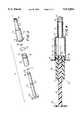
- FIG. 3is an exploded perspective view of the syringe
- FIG. 4is a side elevation, partly in section, showing the plunger mechanism in the fully retracted position
- FIG. 5is a side elevation, partly in section, showing the first discharge position
- FIG. 6is a side elevation, partly in section, showing the fully extended second discharge position.
- FIG. 1 of the drawingsillustrates a prior art syringe having a threaded design.
- the syringecomprises a body 1 which is a hollow tube having a circular cross-section. The distal end of the body terminates in a nozzle 2.
- a threaded half nut 3is integral with the proximal end of the body and this half nut is provided with a releasable lock 4.
- a plungercomprising a threaded shaft 5 is positioned to be slidably moved within the hollow body. The distal end of the plunger shaft accommodates a seal 6 which frictionally engages the wall of the syringe body.
- the proximal end of the shaftterminates in a handle 7 which enables the plunger to be slidably moved forwardly and backwardly within the hollow tubular body.
- the plungermay be moved freely forward and backward within the hollow body.
- the plungermay be moved only by rotating the threaded shaft relative thereto. The screw thread enables maximum pressure to be exerted on the fluid delivered by the syringe but operation of this device usually requires two hands.
- FIG. 2 of the drawingsA standard prior art single action syringe is illustrated in FIG. 2 of the drawings.
- This syringealso comprises a hollow tube body 1' having a circular cross-section.
- the distal end of the bodyterminates in a nozzle 2'.
- the proximal end of the bodyterminates in a circular flange.
- a plungercomprising a fluted rigid shaft 9 is positioned to be slidably moved within the hollow body.
- the distal end of the plungeraccommodates a seal 6' which frictionally engages the wall of the body.
- This syringenormally may be operated with one hand but the ultimate pressure obtained thereby is not always sufficient to fully inflate a balloon catheter to its optimum dilation.
- FIGS. 3-6 of the drawingsA preferred embodiment of a syringe according to the invention is illustrated in FIGS. 3-6 of the drawings.
- the syringecomprises a hollow body 11 having a rear portion 12 and an integrally connected front portion 13.
- the rear portiondefines a rear chamber having a proximal end which terminates in an external flange 14, and a distal end 15.
- the front portiondefines a front chamber having a proximal end 16 which is integral with the distal end of the rear chamber and a distal end which terminates in a nozzle 17.
- the cross-section of both the rear chamber and the front chamberis circular and the internal cross-sectional area of the rear chamber is greater than that of the front chamber.
- the ratio between the cross-sectional area of the rear chamber and the cross-sectional area of the front chamberis about 3:1, providing an operational pressure differential of this order.
- a standard luer type screw connector 18is attached to the distal end of the front chamber to facilitate connection with a mating connector on the tube or device, for example, a balloon catheter, to be serviced by the syringe.
- a double action plunger mechanism 19 adapted to be slidably moved within the hollow bodycomprises a primary plunger 20 having a proximal end 21 and a distal end 22, and a secondary plunger 23 having a proximal end which terminates in a handle 24, and a distal end 25.
- the primary plungerhas a circumferential groove 26 which accommodates an O-ring seal 27 which provides a fluid-tight seal between the primary plunger and the internal wall of the rear chamber while still allowing slidable movement of the plunger within the chamber.
- the primary plungerhas a coaxial tunnel extending longitudinally along its complete length, which tunnel is adapted to telescopically accommodate the secondary plunger 23.
- the secondary plungerhas a first circumferential groove 28 adjacent its distal end 25 and a second circumferential groove 29 located proximal to the first groove.
- the first grooveaccommodates an O-ring seal 30 and the second groove accommodates a similar O-ring seal 31.
- the secondary plungerIn operating the syringe the secondary plunger is telescopically mounted within the coaxial tunnel of the primary plunger and the O-ring seals provide a fluid-tight seal between the secondary plunger and the inner wall of the tunnel as illustrated in FIGS. 4, 5 and 6 and between the secondary plunger and the internal wall of the front chamber as illustrated in FIG. 6.
- the seals around the secondary plungeralso serve to control the slidable movement of the combination primary and secondary plungers both relative to the rear and front chambers and to each other.
- a circumferential flange 32 on the inner wall of the tunnel adjacent the distal end of the primary plungeracts as a stop and prevents the secondary plunger from being pulled clear of the syringe.
- an internal lip 33 at the proximal end of the rear chamberprevents the primary plunger from being pulled clear of the syringe.
- the syringe as described aboveis filled with liquid for inflating a balloon catheter by dipping the nozzle into a container of liquid, for example, sterile saline solution, with the plunger mechanism in the fully extended position (FIG. 6), and withdrawing the plunger mechanism to the fully retracted position (FIG. 4).
- liquidfor example, sterile saline solution
- the filling of a high pressure balloon catheter by the syringe, filled with liquid as described above,is accomplished by attaching the catheter, through an appropriate connector, to the luer connector 18 and forcing the secondary plunger forward.
- the primary plungeris moved forward by the frictional contact with the second (rear) seal of the secondary plunger as the secondary plunger is pushed forward by the handle 24.
- the plunger mechanismis moved forward as one unit from the fully retracted position of FIG. 4 to the first discharge position of FIG. 5, thus delivering the liquid in the rear chamber to the catheter. This delivery serves to initially fill the balloon of the catheter.
- Calibrated gradations(usually in cc) on the wall of the syringe chambers (not shown) indicate the actual volume of liquid delivered.
- the syringeoperates in a similar way to that of any standard syringe.
- withdrawal of the secondary plungerwill in turn act on the primary plunger, thereby pulling back the entire plunger mechanism and extracting the liquid from the balloon.
Landscapes
- Health & Medical Sciences (AREA)
- Vascular Medicine (AREA)
- Engineering & Computer Science (AREA)
- Anesthesiology (AREA)
- Biomedical Technology (AREA)
- Heart & Thoracic Surgery (AREA)
- Hematology (AREA)
- Life Sciences & Earth Sciences (AREA)
- Animal Behavior & Ethology (AREA)
- General Health & Medical Sciences (AREA)
- Public Health (AREA)
- Veterinary Medicine (AREA)
- Infusion, Injection, And Reservoir Apparatuses (AREA)
Abstract
Description
Claims (6)
Priority Applications (8)
| Application Number | Priority Date | Filing Date | Title |
|---|---|---|---|
| US08/442,070US5512054A (en) | 1995-05-16 | 1995-05-16 | Dual action syringe |
| CA002218734ACA2218734C (en) | 1995-05-16 | 1996-04-18 | Dual action syringe |
| JP08524503AJP3097922B2 (en) | 1995-05-16 | 1996-04-18 | Dual action syringe |
| DE69608954TDE69608954T2 (en) | 1995-05-16 | 1996-04-18 | SYRINGE WITH DOUBLE ACTUATION |
| AU51607/96AAU693671B2 (en) | 1995-05-16 | 1996-04-18 | Dual action syringe |
| PCT/IB1996/000347WO1996036379A1 (en) | 1995-05-16 | 1996-04-18 | Dual action syringe |
| EP96908304AEP0814857B1 (en) | 1995-05-16 | 1996-04-18 | Dual action syringe |
| MX9708825AMX9708825A (en) | 1995-05-16 | 1996-04-18 | Dual action syringe. |
Applications Claiming Priority (1)
| Application Number | Priority Date | Filing Date | Title |
|---|---|---|---|
| US08/442,070US5512054A (en) | 1995-05-16 | 1995-05-16 | Dual action syringe |
Publications (1)
| Publication Number | Publication Date |
|---|---|
| US5512054Atrue US5512054A (en) | 1996-04-30 |
Family
ID=23755424
Family Applications (1)
| Application Number | Title | Priority Date | Filing Date |
|---|---|---|---|
| US08/442,070Expired - LifetimeUS5512054A (en) | 1995-05-16 | 1995-05-16 | Dual action syringe |
Country Status (8)
| Country | Link |
|---|---|
| US (1) | US5512054A (en) |
| EP (1) | EP0814857B1 (en) |
| JP (1) | JP3097922B2 (en) |
| AU (1) | AU693671B2 (en) |
| CA (1) | CA2218734C (en) |
| DE (1) | DE69608954T2 (en) |
| MX (1) | MX9708825A (en) |
| WO (1) | WO1996036379A1 (en) |
Cited By (48)
| Publication number | Priority date | Publication date | Assignee | Title |
|---|---|---|---|---|
| US5782803A (en)* | 1996-11-26 | 1998-07-21 | Jentzen; S. William | Low dead space, interchangeable needle syringe |
| US6053894A (en)* | 1997-08-04 | 2000-04-25 | Shadd, Jr.; Daniel L. | Hypodermic syringe |
| EP1008359A4 (en)* | 1997-08-01 | 2000-11-29 | Terumo Corp | Medical container |
| US6641587B2 (en)* | 1998-08-14 | 2003-11-04 | Kyphon Inc. | Systems and methods for treating vertebral bodies |
| US20040030345A1 (en)* | 2002-08-09 | 2004-02-12 | Aurin Gary Douglas | Bone cement syringe |
| US6719735B1 (en) | 2003-02-28 | 2004-04-13 | Gammon Technical Products, Inc. | Syringe adapter |
| WO2006079270A1 (en)* | 2005-01-31 | 2006-08-03 | Ning Tang | A microfluid continuous deliver device |
| US20060178641A1 (en)* | 2004-12-03 | 2006-08-10 | Reynolds David L | Extensible plunger rod for pharmaceutical delivery device |
| US20060258977A1 (en)* | 2005-05-02 | 2006-11-16 | Lee Martin N | Autoflush syringe |
| WO2007008721A1 (en) | 2005-07-07 | 2007-01-18 | Crosstrees Medical, Inc. | Device for delivery of bone void filling materials |
| US20070055283A1 (en)* | 1998-08-14 | 2007-03-08 | Kyphon Inc. | Systems and methods for placing materials into bone |
| US20070185496A1 (en)* | 2004-02-18 | 2007-08-09 | Lorne Beckman | Device for injecting a viscous material into a hard tissue |
| US20070191860A1 (en)* | 2006-01-30 | 2007-08-16 | Sdgi Holdings, Inc. | Intervertebral prosthetic disc inserter |
| US20080021457A1 (en)* | 2006-07-05 | 2008-01-24 | Warsaw Orthopedic Inc. | Zygapophysial joint repair system |
| US20100217274A1 (en)* | 2005-04-15 | 2010-08-26 | Abbott Medical Optics Inc. | Multi-action device for inserting an intraocular lens into an eye |
| US20100292672A1 (en)* | 2005-05-02 | 2010-11-18 | Lee Martin N | Autoflush syringe |
| WO2011032952A1 (en)* | 2009-09-16 | 2011-03-24 | Sanofi-Aventis Deutschland Gmbh | Medication delivery device and method for dispensing a medication |
| US20110218513A1 (en)* | 2010-03-05 | 2011-09-08 | Medicinelodge, Inc. Dba Imds Co-Innovation | Biologics Delivery System |
| US20110282197A1 (en)* | 2009-02-04 | 2011-11-17 | Martz Kevin R | Hand-Activated Syringe with Vacuum Chamber for Auto Refill |
| EP2563430A2 (en)* | 2010-04-30 | 2013-03-06 | Bayer Pharma Aktiengesellschaft | Displacement syringe |
| JP2013049462A (en)* | 2011-08-31 | 2013-03-14 | Pentel Corp | Metered discharge container |
| US20130079729A1 (en)* | 2010-03-31 | 2013-03-28 | Terumo Kabushiki Kaisha | Injection Needle Assembly And Drug Injection Device |
| US20140276581A1 (en)* | 2013-03-13 | 2014-09-18 | Nordson Corporation | Assembly for dispensing biomaterial, plunger therefor, and related methods |
| WO2015006430A1 (en)* | 2013-07-10 | 2015-01-15 | Bayer Medical Care Inc. | Vacuum system for a piston and syringe interface |
| US8936577B2 (en) | 2005-05-02 | 2015-01-20 | Shi Zi Technology, Ltd. | Methods and devices for autoflush syringes |
| US9408981B2 (en) | 2013-03-10 | 2016-08-09 | Bayer Healthcare Llc | Adjustable volume syringe |
| US9480797B1 (en) | 2015-10-28 | 2016-11-01 | Bayer Healthcare Llc | System and method for syringe plunger engagement with an injector |
| US9694131B2 (en) | 2003-11-25 | 2017-07-04 | Bayer Healthcare Llc | Medical injector system |
| US9744305B2 (en) | 2012-09-28 | 2017-08-29 | Bayer Healthcare Llc | Quick release plunger |
| EP3254717A1 (en)* | 2016-06-09 | 2017-12-13 | Novartis Ag | Syringe and method for dispensing a liquid |
| US9844622B2 (en) | 2000-07-10 | 2017-12-19 | Bayer Healthcare Llc | Syringes for medical injector systems |
| US9855390B2 (en) | 2006-03-15 | 2018-01-02 | Bayer Healthcare Llc | Plunger covers and plungers for use in syringes |
| US9855385B2 (en) | 2013-03-13 | 2018-01-02 | Bayer Healthcare Llc | Multiple compartment syringe |
| US9861752B2 (en) | 2014-04-18 | 2018-01-09 | Covidien Lp | Mixing nozzle |
| US9895289B2 (en)* | 2014-04-18 | 2018-02-20 | Covidien Lp | Mixing syringe |
| WO2019014410A2 (en) | 2017-07-12 | 2019-01-17 | Edwards Lifesciences Corporation | Reduced operation force inflator |
| USD847985S1 (en) | 2007-03-14 | 2019-05-07 | Bayer Healthcare Llc | Syringe plunger cover |
| US20190217068A1 (en)* | 2012-09-21 | 2019-07-18 | Merit Medical Systems, Inc. | Variable displacement inflation devices and methods of use |
| US10806852B2 (en) | 2014-03-19 | 2020-10-20 | Bayer Healthcare Llc | System for syringe engagement to an injector |
| USD942005S1 (en) | 2007-03-14 | 2022-01-25 | Bayer Healthcare Llc | Orange syringe plunger cover |
| US11724036B2 (en)* | 2016-12-12 | 2023-08-15 | Orchid Holdings, Llc | Syringe for processing fat grafts and related methods |
| USD1002840S1 (en) | 2007-03-14 | 2023-10-24 | Bayer Healthcare Llc | Syringe plunger |
| US11883636B2 (en) | 2018-02-27 | 2024-01-30 | Bayer Healthcare Llc | Syringe plunger engagement mechanism |
| US11969582B2 (en) | 2017-01-06 | 2024-04-30 | Bayer Healthcare Llc | Syringe plunger with dynamic seal |
| US11998718B2 (en) | 2020-06-18 | 2024-06-04 | Bayer Healthcare Llc | System and method for syringe plunger engagement with an injector |
| USD1031029S1 (en) | 2003-11-25 | 2024-06-11 | Bayer Healthcare Llc | Syringe plunger |
| WO2024184293A1 (en)* | 2023-03-06 | 2024-09-12 | Boehringer Ingelheim Vetmedica Gmbh | Systems for delivery of liquid pharmaceutical compositions in particular comprising one or more sglt-2 inhibitor(s) |
| US12121683B2 (en)* | 2021-10-15 | 2024-10-22 | Atrion Medical Products, Inc. | Advanced actuating mechanism and method of operation for fluid displacement and pressurizing device |
Families Citing this family (6)
| Publication number | Priority date | Publication date | Assignee | Title |
|---|---|---|---|---|
| KR930024107A (en)* | 1992-05-26 | 1993-12-21 | 양승택 | Dummy Diffraction Mask |
| JP5385074B2 (en)* | 2009-09-29 | 2014-01-08 | テルモ株式会社 | Drug infusion tool |
| JP5695484B2 (en)* | 2011-04-28 | 2015-04-08 | 株式会社吉野工業所 | Syringe |
| JP5695485B2 (en)* | 2011-04-28 | 2015-04-08 | 株式会社吉野工業所 | Syringe |
| KR200473761Y1 (en)* | 2012-12-27 | 2014-07-31 | 이문용 | A umbrella having water gun |
| JP7517160B2 (en)* | 2021-01-14 | 2024-07-17 | ニプロ株式会社 | Sprayer |
Citations (8)
| Publication number | Priority date | Publication date | Assignee | Title |
|---|---|---|---|---|
| US3985122A (en)* | 1975-06-04 | 1976-10-12 | Medical Development Corporation | Multi-piston syringe device |
| US4188949A (en)* | 1977-07-05 | 1980-02-19 | Becton, Dickinson & Company | Sequential injection syringe |
| US4583974A (en)* | 1984-04-04 | 1986-04-22 | Kokernak Denis T | Syringe for balloon dilation catheters |
| US4758223A (en)* | 1986-07-02 | 1988-07-19 | Schneider-Shiley (Usa) Inc. | Inflation device for angioplasty catheter |
| US5047015A (en)* | 1989-03-17 | 1991-09-10 | Merit Medical Systems, Inc. | Locking syringe |
| US5057078A (en)* | 1989-03-17 | 1991-10-15 | Merit Medical Systems, Inc. | Locking syringe |
| US5209732A (en)* | 1989-03-17 | 1993-05-11 | Merit Medical Systems, Inc. | Locking syringe with thread-release lock |
| US5354285A (en)* | 1991-11-29 | 1994-10-11 | Sergej Mikhailovich Masurik | Injection syringe |
Family Cites Families (1)
| Publication number | Priority date | Publication date | Assignee | Title |
|---|---|---|---|---|
| US4213456A (en)* | 1978-01-07 | 1980-07-22 | Bottger Paul E K | Medical multi-purpose instrument |
- 1995
- 1995-05-16USUS08/442,070patent/US5512054A/ennot_activeExpired - Lifetime
- 1996
- 1996-04-18WOPCT/IB1996/000347patent/WO1996036379A1/enactiveIP Right Grant
- 1996-04-18AUAU51607/96Apatent/AU693671B2/ennot_activeCeased
- 1996-04-18DEDE69608954Tpatent/DE69608954T2/ennot_activeExpired - Fee Related
- 1996-04-18EPEP96908304Apatent/EP0814857B1/ennot_activeExpired - Lifetime
- 1996-04-18JPJP08524503Apatent/JP3097922B2/ennot_activeExpired - Fee Related
- 1996-04-18CACA002218734Apatent/CA2218734C/ennot_activeExpired - Fee Related
- 1996-04-18MXMX9708825Apatent/MX9708825A/ennot_activeIP Right Cessation
Patent Citations (8)
| Publication number | Priority date | Publication date | Assignee | Title |
|---|---|---|---|---|
| US3985122A (en)* | 1975-06-04 | 1976-10-12 | Medical Development Corporation | Multi-piston syringe device |
| US4188949A (en)* | 1977-07-05 | 1980-02-19 | Becton, Dickinson & Company | Sequential injection syringe |
| US4583974A (en)* | 1984-04-04 | 1986-04-22 | Kokernak Denis T | Syringe for balloon dilation catheters |
| US4758223A (en)* | 1986-07-02 | 1988-07-19 | Schneider-Shiley (Usa) Inc. | Inflation device for angioplasty catheter |
| US5047015A (en)* | 1989-03-17 | 1991-09-10 | Merit Medical Systems, Inc. | Locking syringe |
| US5057078A (en)* | 1989-03-17 | 1991-10-15 | Merit Medical Systems, Inc. | Locking syringe |
| US5209732A (en)* | 1989-03-17 | 1993-05-11 | Merit Medical Systems, Inc. | Locking syringe with thread-release lock |
| US5354285A (en)* | 1991-11-29 | 1994-10-11 | Sergej Mikhailovich Masurik | Injection syringe |
Cited By (95)
| Publication number | Priority date | Publication date | Assignee | Title |
|---|---|---|---|---|
| US5782803A (en)* | 1996-11-26 | 1998-07-21 | Jentzen; S. William | Low dead space, interchangeable needle syringe |
| US5902269A (en)* | 1996-11-26 | 1999-05-11 | Jentzen; S. William | Low dead space, interchangeable needle syringe |
| EP1008359A4 (en)* | 1997-08-01 | 2000-11-29 | Terumo Corp | Medical container |
| US6053894A (en)* | 1997-08-04 | 2000-04-25 | Shadd, Jr.; Daniel L. | Hypodermic syringe |
| US20070055283A1 (en)* | 1998-08-14 | 2007-03-08 | Kyphon Inc. | Systems and methods for placing materials into bone |
| US20080065091A1 (en)* | 1998-08-14 | 2008-03-13 | Kyphon Inc. | Methods and apparatus for placing materials into bone |
| US20040049203A1 (en)* | 1998-08-14 | 2004-03-11 | Kyphon Inc. | Systems and methods for treating vertebral bodies |
| US20110022051A1 (en)* | 1998-08-14 | 2011-01-27 | Kyphon Sarl | Systems and methods for placing materials into bone |
| US7708742B2 (en)* | 1998-08-14 | 2010-05-04 | Kyphon Sarl | Methods for placing materials into bone |
| US20080065090A1 (en)* | 1998-08-14 | 2008-03-13 | Scribner Robert M | Methods and apparatus for placing materials into bone |
| US7252671B2 (en) | 1998-08-14 | 2007-08-07 | Kyphon Inc. | Systems and methods for treating vertebral bodies |
| US6641587B2 (en)* | 1998-08-14 | 2003-11-04 | Kyphon Inc. | Systems and methods for treating vertebral bodies |
| US7771431B2 (en)* | 1998-08-14 | 2010-08-10 | Kyphon SÀRL | Systems and methods for placing materials into bone |
| US20070073307A1 (en)* | 1998-08-14 | 2007-03-29 | Kyphon Inc. | Methods for placing materials into bone |
| US20070093847A1 (en)* | 1998-08-14 | 2007-04-26 | Kyphon Inc. | Methods for placing materials into bone |
| US9844622B2 (en) | 2000-07-10 | 2017-12-19 | Bayer Healthcare Llc | Syringes for medical injector systems |
| US20040030345A1 (en)* | 2002-08-09 | 2004-02-12 | Aurin Gary Douglas | Bone cement syringe |
| US6719735B1 (en) | 2003-02-28 | 2004-04-13 | Gammon Technical Products, Inc. | Syringe adapter |
| US9694131B2 (en) | 2003-11-25 | 2017-07-04 | Bayer Healthcare Llc | Medical injector system |
| US10434249B2 (en) | 2003-11-25 | 2019-10-08 | Bayer Healthcare Llc | Medical injector system |
| US10894124B2 (en) | 2003-11-25 | 2021-01-19 | Bayer Healthcare Llc | Medical injector system |
| US11596735B2 (en) | 2003-11-25 | 2023-03-07 | Bayer Healthcare Llc | Medical injector system |
| USD1031029S1 (en) | 2003-11-25 | 2024-06-11 | Bayer Healthcare Llc | Syringe plunger |
| US20070185496A1 (en)* | 2004-02-18 | 2007-08-09 | Lorne Beckman | Device for injecting a viscous material into a hard tissue |
| US20060178641A1 (en)* | 2004-12-03 | 2006-08-10 | Reynolds David L | Extensible plunger rod for pharmaceutical delivery device |
| WO2006079270A1 (en)* | 2005-01-31 | 2006-08-03 | Ning Tang | A microfluid continuous deliver device |
| US20100217274A1 (en)* | 2005-04-15 | 2010-08-26 | Abbott Medical Optics Inc. | Multi-action device for inserting an intraocular lens into an eye |
| US8926628B2 (en)* | 2005-04-15 | 2015-01-06 | Abbott Medical Optics Inc. | Multi-action device for inserting an intraocular lens into an eye |
| US8936577B2 (en) | 2005-05-02 | 2015-01-20 | Shi Zi Technology, Ltd. | Methods and devices for autoflush syringes |
| US10322236B2 (en) | 2005-05-02 | 2019-06-18 | Bee Sight Limited | Methods and devices for autoflush syringes |
| US20090287184A1 (en)* | 2005-05-02 | 2009-11-19 | Martin Nicholas Lee | Autoflush Syringe Method |
| US20100292672A1 (en)* | 2005-05-02 | 2010-11-18 | Lee Martin N | Autoflush syringe |
| US20060258977A1 (en)* | 2005-05-02 | 2006-11-16 | Lee Martin N | Autoflush syringe |
| US8075547B2 (en) | 2005-05-02 | 2011-12-13 | Preventiv, Inc. | Autoflush syringe method |
| US8075533B2 (en) | 2005-05-02 | 2011-12-13 | Preventiv, Inc. | Autoflush syringe |
| US8529517B2 (en) | 2005-05-02 | 2013-09-10 | Shi Zi Technology, Ltd. | Autoflush syringe |
| US9539391B2 (en) | 2005-05-02 | 2017-01-10 | Shi Zi Technology, Ltd. | Methods and devices for autoflush syringes |
| US20100114068A2 (en)* | 2005-05-02 | 2010-05-06 | Martin Lee | Autoflush Syringe Method |
| US11389589B2 (en) | 2005-05-02 | 2022-07-19 | Bee Sight Llc | Methods and devices for autoflush syringes |
| US20090149860A1 (en)* | 2005-07-07 | 2009-06-11 | Scribner Robert M | Device for delivery of bone void filling materials |
| WO2007008721A1 (en) | 2005-07-07 | 2007-01-18 | Crosstrees Medical, Inc. | Device for delivery of bone void filling materials |
| EP1903961A4 (en)* | 2005-07-07 | 2010-08-04 | Crosstrees Medical Inc | Device for delivery of bone void filling materials |
| US20070191860A1 (en)* | 2006-01-30 | 2007-08-16 | Sdgi Holdings, Inc. | Intervertebral prosthetic disc inserter |
| US10668221B2 (en) | 2006-03-15 | 2020-06-02 | Bayer Healthcare Llc | Plunger covers and plungers for use in syringes |
| US9855390B2 (en) | 2006-03-15 | 2018-01-02 | Bayer Healthcare Llc | Plunger covers and plungers for use in syringes |
| US20080021457A1 (en)* | 2006-07-05 | 2008-01-24 | Warsaw Orthopedic Inc. | Zygapophysial joint repair system |
| USD1030052S1 (en) | 2007-03-14 | 2024-06-04 | Bayer Healthcare Llc | Syringe plunger |
| USD847985S1 (en) | 2007-03-14 | 2019-05-07 | Bayer Healthcare Llc | Syringe plunger cover |
| USD942005S1 (en) | 2007-03-14 | 2022-01-25 | Bayer Healthcare Llc | Orange syringe plunger cover |
| USD1002840S1 (en) | 2007-03-14 | 2023-10-24 | Bayer Healthcare Llc | Syringe plunger |
| USD1030051S1 (en) | 2007-03-14 | 2024-06-04 | Bayer Healthcare Llc | Syringe plunger |
| US10166337B2 (en) | 2009-02-04 | 2019-01-01 | Liebel-Flarsheim Company Llc | Hand-actuated syringe with vacuum chamber for auto refill |
| US20110282197A1 (en)* | 2009-02-04 | 2011-11-17 | Martz Kevin R | Hand-Activated Syringe with Vacuum Chamber for Auto Refill |
| US9242048B2 (en) | 2009-09-16 | 2016-01-26 | Sanofi-Aventis Deutschland Gmbh | Medication delivery device and method for dispensing a medication |
| WO2011032952A1 (en)* | 2009-09-16 | 2011-03-24 | Sanofi-Aventis Deutschland Gmbh | Medication delivery device and method for dispensing a medication |
| US8628536B2 (en)* | 2010-03-05 | 2014-01-14 | Imds Corporation | Biologics delivery system |
| US20110218513A1 (en)* | 2010-03-05 | 2011-09-08 | Medicinelodge, Inc. Dba Imds Co-Innovation | Biologics Delivery System |
| TWI619523B (en)* | 2010-03-31 | 2018-04-01 | 泰爾茂股份有限公司 | Drug dosing tool and drug injection apparatus |
| US20130079729A1 (en)* | 2010-03-31 | 2013-03-28 | Terumo Kabushiki Kaisha | Injection Needle Assembly And Drug Injection Device |
| US9302051B2 (en)* | 2010-03-31 | 2016-04-05 | Terumo Kabushiki Kaisha | Injection needle assembly and drug injection device |
| CN103037921A (en)* | 2010-04-30 | 2013-04-10 | 拜耳药业股份公司 | Displacement Syringe |
| US20130126559A1 (en)* | 2010-04-30 | 2013-05-23 | Bayer Intellectual Property Gmbh | Displacement Syringe |
| EP2563430A2 (en)* | 2010-04-30 | 2013-03-06 | Bayer Pharma Aktiengesellschaft | Displacement syringe |
| JP2013049462A (en)* | 2011-08-31 | 2013-03-14 | Pentel Corp | Metered discharge container |
| US20190217068A1 (en)* | 2012-09-21 | 2019-07-18 | Merit Medical Systems, Inc. | Variable displacement inflation devices and methods of use |
| US9744305B2 (en) | 2012-09-28 | 2017-08-29 | Bayer Healthcare Llc | Quick release plunger |
| US10286152B2 (en) | 2012-09-28 | 2019-05-14 | Bayer Healthcare Llc | Quick release plunger |
| US9408981B2 (en) | 2013-03-10 | 2016-08-09 | Bayer Healthcare Llc | Adjustable volume syringe |
| US10172660B2 (en)* | 2013-03-13 | 2019-01-08 | Nordson Corporation | Assembly for dispensing biomaterial, plunger therefor, and related methods |
| US10966770B2 (en) | 2013-03-13 | 2021-04-06 | Nordson Corporation | Assembly for dispensing biomaterial, plunger therefor, and related methods |
| US9855385B2 (en) | 2013-03-13 | 2018-01-02 | Bayer Healthcare Llc | Multiple compartment syringe |
| US20140276581A1 (en)* | 2013-03-13 | 2014-09-18 | Nordson Corporation | Assembly for dispensing biomaterial, plunger therefor, and related methods |
| WO2015006430A1 (en)* | 2013-07-10 | 2015-01-15 | Bayer Medical Care Inc. | Vacuum system for a piston and syringe interface |
| US11103637B2 (en) | 2014-03-19 | 2021-08-31 | Bayer Healthcare Llc | System for syringe engagement to an injector |
| US10806852B2 (en) | 2014-03-19 | 2020-10-20 | Bayer Healthcare Llc | System for syringe engagement to an injector |
| US11383029B2 (en) | 2014-03-19 | 2022-07-12 | Bayer Healthcare Llc | System for syringe engagement to an injector |
| US9895289B2 (en)* | 2014-04-18 | 2018-02-20 | Covidien Lp | Mixing syringe |
| US9861752B2 (en) | 2014-04-18 | 2018-01-09 | Covidien Lp | Mixing nozzle |
| US12102793B2 (en) | 2015-10-28 | 2024-10-01 | Bayer Healthcare Llc | System and method for syringe plunger engagement with an injector |
| US9480797B1 (en) | 2015-10-28 | 2016-11-01 | Bayer Healthcare Llc | System and method for syringe plunger engagement with an injector |
| US11547794B2 (en) | 2015-10-28 | 2023-01-10 | Bayer Healthcare Llc | System and method for syringe plunger engagement with an injector |
| US10512721B2 (en) | 2015-10-28 | 2019-12-24 | Bayer Healthcare Llc | System and method for syringe plunger engagement with an injector |
| WO2017212033A1 (en)* | 2016-06-09 | 2017-12-14 | Novartis Ag | Syringe and method for dispensing a liquid |
| EP3254717A1 (en)* | 2016-06-09 | 2017-12-13 | Novartis Ag | Syringe and method for dispensing a liquid |
| US11724036B2 (en)* | 2016-12-12 | 2023-08-15 | Orchid Holdings, Llc | Syringe for processing fat grafts and related methods |
| US11969582B2 (en) | 2017-01-06 | 2024-04-30 | Bayer Healthcare Llc | Syringe plunger with dynamic seal |
| US20190015642A1 (en)* | 2017-07-12 | 2019-01-17 | Edwards Lifesciences Corporation | Reduced operation force inflator |
| US10857334B2 (en)* | 2017-07-12 | 2020-12-08 | Edwards Lifesciences Corporation | Reduced operation force inflator |
| EP3651696A4 (en)* | 2017-07-12 | 2020-07-29 | Edwards Lifesciences Corporation | Reduced operation force inflator |
| WO2019014410A2 (en) | 2017-07-12 | 2019-01-17 | Edwards Lifesciences Corporation | Reduced operation force inflator |
| US11883636B2 (en) | 2018-02-27 | 2024-01-30 | Bayer Healthcare Llc | Syringe plunger engagement mechanism |
| US11998718B2 (en) | 2020-06-18 | 2024-06-04 | Bayer Healthcare Llc | System and method for syringe plunger engagement with an injector |
| US12121683B2 (en)* | 2021-10-15 | 2024-10-22 | Atrion Medical Products, Inc. | Advanced actuating mechanism and method of operation for fluid displacement and pressurizing device |
| US12138408B2 (en)* | 2021-10-15 | 2024-11-12 | Atrion Medical Products, Inc. | Advanced actuating mechanism and method of operation for fluid displacement and pressurizing device |
| WO2024184293A1 (en)* | 2023-03-06 | 2024-09-12 | Boehringer Ingelheim Vetmedica Gmbh | Systems for delivery of liquid pharmaceutical compositions in particular comprising one or more sglt-2 inhibitor(s) |
Also Published As
| Publication number | Publication date |
|---|---|
| CA2218734A1 (en) | 1996-11-21 |
| JP3097922B2 (en) | 2000-10-10 |
| EP0814857B1 (en) | 2000-06-21 |
| EP0814857A1 (en) | 1998-01-07 |
| CA2218734C (en) | 2001-09-04 |
| JPH10506557A (en) | 1998-06-30 |
| DE69608954D1 (en) | 2000-07-27 |
| MX9708825A (en) | 1998-02-28 |
| WO1996036379A1 (en) | 1996-11-21 |
| AU693671B2 (en) | 1998-07-02 |
| DE69608954T2 (en) | 2000-10-19 |
| AU5160796A (en) | 1996-11-29 |
Similar Documents
| Publication | Publication Date | Title |
|---|---|---|
| US5512054A (en) | Dual action syringe | |
| MXPA97008825A (en) | Action syringe d | |
| US4929238A (en) | Multi-pressure injector device | |
| US4758223A (en) | Inflation device for angioplasty catheter | |
| US4919121A (en) | Inflation device for angioplasty catheter | |
| US4723938A (en) | Single plunger inflation device for angioplasty catheter | |
| JP5114426B2 (en) | Method and apparatus for controllably occluding a blood vessel | |
| US6511459B1 (en) | Syringe plunger having an improved sealing ability | |
| US4838864A (en) | Pressure controller | |
| JP4263171B2 (en) | Administration device with priming function | |
| CA1272091A (en) | Refillable injection device | |
| EP0863777B1 (en) | Limited backflow reflux valve | |
| US8075547B2 (en) | Autoflush syringe method | |
| US6234996B1 (en) | Integrated inflation/deflation device and method | |
| US4861340A (en) | Hand-held pneumatic power assisted syringe | |
| US4044757A (en) | Cholangiography device and method | |
| US5447672A (en) | Manufacture of capillary tubing | |
| EP1499371B1 (en) | Multi-dose infusion pump providing minimal flow between doses | |
| JP3229833B2 (en) | Fluid transfer device | |
| EP0945150B1 (en) | Liquid medicine injection apparatus utilizing negative pressure | |
| US20030120217A1 (en) | Methods and devices for sclerotherapy | |
| CA2273172C (en) | Balloon catheter | |
| US4333460A (en) | Enema apparata improvements relating double contrast studies | |
| US4386607A (en) | Enema apparata improvements relating to double contrast studies | |
| EP1341574B1 (en) | Inflation device with storage chamber |
Legal Events
| Date | Code | Title | Description |
|---|---|---|---|
| AS | Assignment | Owner name:AMERICAN MEDICAL SYSTEMS, INC., MINNESOTA Free format text:ASSIGNMENT OF ASSIGNORS INTEREST;ASSIGNOR:MORNINGSTAR, RANDY L.;REEL/FRAME:007517/0203 Effective date:19950515 | |
| FEPP | Fee payment procedure | Free format text:PAYOR NUMBER ASSIGNED (ORIGINAL EVENT CODE: ASPN); ENTITY STATUS OF PATENT OWNER: LARGE ENTITY | |
| STCF | Information on status: patent grant | Free format text:PATENTED CASE | |
| FEPP | Fee payment procedure | Free format text:PAYOR NUMBER ASSIGNED (ORIGINAL EVENT CODE: ASPN); ENTITY STATUS OF PATENT OWNER: LARGE ENTITY Free format text:PAYER NUMBER DE-ASSIGNED (ORIGINAL EVENT CODE: RMPN); ENTITY STATUS OF PATENT OWNER: LARGE ENTITY | |
| FPAY | Fee payment | Year of fee payment:4 | |
| AS | Assignment | Owner name:WPAMS ACQUISITION CORP., NEW YORK Free format text:ASSIGNMENT OF ASSIGNORS INTEREST;ASSIGNOR:AMERICAN MEDICAL SYSTEMS, INC.;REEL/FRAME:010685/0496 Effective date:19980910 Owner name:AMERICAN MEDICAL SYSTEMS, INC., MINNESOTA Free format text:ASSIGNMENT OF ASSIGNORS INTEREST;ASSIGNOR:WPAMS ACQUISITION CORP.;REEL/FRAME:010685/0505 Effective date:19980702 | |
| AS | Assignment | Owner name:BANK OF AMERICA, N.A., AS AGENT, NORTH CAROLINA Free format text:NOTICE OF GRANT OF SECURITY INTEREST;ASSIGNOR:AMERICAN MEDICAL SYSTEMS, INC., F/K/A WPAMS ACQUISITION CORP.;REEL/FRAME:010795/0619 Effective date:20000417 | |
| AS | Assignment | Owner name:BANK OF AMERICA, N.A., AS AGENT, NORTH CAROLINA Free format text:NOTICE OF GRANT OF SECURITY INTERST;ASSIGNOR:AMERICAN MEDICAL SYSTEMS, INC.;REEL/FRAME:014186/0257 Effective date:20000417 | |
| AS | Assignment | Owner name:AMS RESEARCH CORPORATION, MINNESOTA Free format text:ASSIGNMENT OF ASSIGNORS INTEREST;ASSIGNOR:AMERICAN MEDICAL SYSTEMS INC.;REEL/FRAME:013835/0522 Effective date:20030724 | |
| FPAY | Fee payment | Year of fee payment:8 | |
| AS | Assignment | Owner name:AMERICAN MEDICAL SYSTEMS, INC., MINNESOTA Free format text:SECURITY INTEREST RELEASE;ASSIGNOR:BANK OF AMERICA, N.A.;REEL/FRAME:015596/0795 Effective date:20040701 | |
| AS | Assignment | Owner name:AMERICAN MEDICAL SYSTEMS, INC., MINNESOTA Free format text:RELEASE BY SECURED PARTY;ASSIGNOR:BANK OF AMERICA, N.A., AS AGENT;REEL/FRAME:017846/0709 Effective date:20060628 | |
| AS | Assignment | Owner name:AMERICAN MEDICAL SYSTEMS, INC. F/K/A WPAMS ACQUISI Free format text:RELEASE OF SECURITY INTEREST (SUPERCEDING RELEASE RECORDED ON JULY 30, 2004, AT REEL 015596, FRAME 0795).;ASSIGNOR:BANK OF AMERICA, N.A., AS AGENT;REEL/FRAME:017971/0028 Effective date:20060719 | |
| AS | Assignment | Owner name:AEMRICAN MEDICAL SYSTEMS, INC., MINNESOTA Free format text:RELEASE OF SECURITY INTEREST (SUPERCEEDING RELEASE RECORDED AT REEL/FRAME 017846/0709);ASSIGNOR:BANK OF AMERICA, N.A., AS AGENT;REEL/FRAME:018109/0700 Effective date:20060717 | |
| FPAY | Fee payment | Year of fee payment:12 | |
| REMI | Maintenance fee reminder mailed | ||
| AS | Assignment | Owner name:MORGAN STANLEY SENIOR FUNDING, INC., AS ADMINISTRA Free format text:SECURITY AGREEMENT;ASSIGNOR:AMS RESEARCH CORPORATION;REEL/FRAME:026632/0535 Effective date:20110617 | |
| AS | Assignment | Owner name:AMS RESEARCH CORPORATION, MINNESOTA Free format text:RELEASE OF PATENT SECURITY INTEREST;ASSIGNOR:MORGAN STANLEY SENIOR FUNDING, INC., AS ADMINISTRATIVE AGENT;REEL/FRAME:032380/0053 Effective date:20140228 | |
| AS | Assignment | Owner name:DEUTSCHE BANK AG NEW YORK BRANCH, AS COLLATERAL AGENT, NEW YORK Free format text:GRANT OF SECURITY INTEREST IN PATENTS;ASSIGNORS:ENDO PHARMACEUTICALS SOLUTIONS, INC.;ENDO PHARMACEUTICALS, INC.;AMS RESEARCH CORPORATION;AND OTHERS;REEL/FRAME:032491/0440 Effective date:20140228 Owner name:DEUTSCHE BANK AG NEW YORK BRANCH, AS COLLATERAL AG Free format text:GRANT OF SECURITY INTEREST IN PATENTS;ASSIGNORS:ENDO PHARMACEUTICALS SOLUTIONS, INC.;ENDO PHARMACEUTICALS, INC.;AMS RESEARCH CORPORATION;AND OTHERS;REEL/FRAME:032491/0440 Effective date:20140228 | |
| AS | Assignment | Owner name:AMERICAN MEDICAL SYSTEMS, LLC, MINNESOTA Free format text:RELEASE BY SECURED PARTY;ASSIGNOR:DEUTSCHE BANK AG NEW YORK BRANCH;REEL/FRAME:036285/0146 Effective date:20150803 Owner name:LASERSCOPE, CALIFORNIA Free format text:RELEASE BY SECURED PARTY;ASSIGNOR:DEUTSCHE BANK AG NEW YORK BRANCH;REEL/FRAME:036285/0146 Effective date:20150803 Owner name:AMS RESEARCH, LLC, MINNESOTA Free format text:RELEASE BY SECURED PARTY;ASSIGNOR:DEUTSCHE BANK AG NEW YORK BRANCH;REEL/FRAME:036285/0146 Effective date:20150803 | |
| AS | Assignment | Owner name:BOSTON SCIENTIFIC SCIMED, INC., MINNESOTA Free format text:ASSIGNMENT OF ASSIGNORS INTEREST;ASSIGNOR:AMS RESEARCH, LLC;REEL/FRAME:037901/0941 Effective date:20151210 Owner name:BOSTON SCIENTIFIC SCIMED, INC., MINNESOTA Free format text:ASSIGNMENT OF ASSIGNORS INTEREST;ASSIGNOR:AMERICAN MEDICAL SYSTEMS, LLC;REEL/FRAME:037901/0883 Effective date:20151210 |