US5511749A - Remote control system for a locomotive - Google Patents
Remote control system for a locomotiveDownload PDFInfo
- Publication number
- US5511749A US5511749AUS08/221,704US22170494AUS5511749AUS 5511749 AUS5511749 AUS 5511749AUS 22170494 AUS22170494 AUS 22170494AUS 5511749 AUS5511749 AUS 5511749A
- Authority
- US
- United States
- Prior art keywords
- locomotive
- travel
- signal
- brake
- generating
- Prior art date
- Legal status (The legal status is an assumption and is not a legal conclusion. Google has not performed a legal analysis and makes no representation as to the accuracy of the status listed.)
- Ceased
Links
- 230000003137locomotive effectEffects0.000titleclaimsabstractdescription212
- 230000001133accelerationEffects0.000claimsdescription8
- 230000001276controlling effectEffects0.000claimsdescription8
- 230000008859changeEffects0.000claimsdescription5
- 230000002596correlated effectEffects0.000claimsdescription4
- 230000004044responseEffects0.000claimsdescription4
- 230000005540biological transmissionEffects0.000abstractdescription20
- 230000000694effectsEffects0.000abstractdescription7
- 230000006870functionEffects0.000description16
- 230000033001locomotionEffects0.000description16
- 238000010586diagramMethods0.000description11
- 238000012545processingMethods0.000description8
- 230000008054signal transmissionEffects0.000description6
- 238000012546transferMethods0.000description6
- 238000004422calculation algorithmMethods0.000description5
- 230000008878couplingEffects0.000description4
- 238000010168coupling processMethods0.000description4
- 238000005859coupling reactionMethods0.000description4
- 230000007257malfunctionEffects0.000description4
- 230000002441reversible effectEffects0.000description4
- 238000012360testing methodMethods0.000description4
- 230000009471actionEffects0.000description3
- 230000000875corresponding effectEffects0.000description3
- 238000005259measurementMethods0.000description3
- 230000007246mechanismEffects0.000description3
- 238000004364calculation methodMethods0.000description2
- 238000004891communicationMethods0.000description2
- 238000012937correctionMethods0.000description2
- 239000012530fluidSubstances0.000description2
- 230000005484gravityEffects0.000description2
- 238000012986modificationMethods0.000description2
- 230000004048modificationEffects0.000description2
- 230000007935neutral effectEffects0.000description2
- 239000007787solidSubstances0.000description2
- 230000001360synchronised effectEffects0.000description2
- 230000002123temporal effectEffects0.000description2
- 238000012795verificationMethods0.000description2
- 230000000007visual effectEffects0.000description2
- 238000006243chemical reactionMethods0.000description1
- 239000011248coating agentSubstances0.000description1
- 238000000576coating methodMethods0.000description1
- 238000010276constructionMethods0.000description1
- 238000011109contaminationMethods0.000description1
- 230000000994depressogenic effectEffects0.000description1
- 238000009795derivationMethods0.000description1
- 238000013461designMethods0.000description1
- 238000002592echocardiographyMethods0.000description1
- 230000002708enhancing effectEffects0.000description1
- 239000000446fuelSubstances0.000description1
- 238000002347injectionMethods0.000description1
- 239000007924injectionSubstances0.000description1
- 238000009434installationMethods0.000description1
- 230000003993interactionEffects0.000description1
- 238000000034methodMethods0.000description1
- 238000012544monitoring processMethods0.000description1
- 230000000737periodic effectEffects0.000description1
- 238000002310reflectometryMethods0.000description1
- 238000005096rolling processMethods0.000description1
- 230000011664signalingEffects0.000description1
- XLYOFNOQVPJJNP-UHFFFAOYSA-NwaterSubstancesOXLYOFNOQVPJJNP-UHFFFAOYSA-N0.000description1
Images


Classifications
- B—PERFORMING OPERATIONS; TRANSPORTING
- B61—RAILWAYS
- B61L—GUIDING RAILWAY TRAFFIC; ENSURING THE SAFETY OF RAILWAY TRAFFIC
- B61L17/00—Switching systems for classification yards
- B—PERFORMING OPERATIONS; TRANSPORTING
- B61—RAILWAYS
- B61L—GUIDING RAILWAY TRAFFIC; ENSURING THE SAFETY OF RAILWAY TRAFFIC
- B61L3/00—Devices along the route for controlling devices on the vehicle or train, e.g. to release brake or to operate a warning signal
- B61L3/02—Devices along the route for controlling devices on the vehicle or train, e.g. to release brake or to operate a warning signal at selected places along the route, e.g. intermittent control simultaneous mechanical and electrical control
- B61L3/08—Devices along the route for controlling devices on the vehicle or train, e.g. to release brake or to operate a warning signal at selected places along the route, e.g. intermittent control simultaneous mechanical and electrical control controlling electrically
- B61L3/12—Devices along the route for controlling devices on the vehicle or train, e.g. to release brake or to operate a warning signal at selected places along the route, e.g. intermittent control simultaneous mechanical and electrical control controlling electrically using magnetic or electrostatic induction; using radio waves
- B61L3/126—Constructional details
- B—PERFORMING OPERATIONS; TRANSPORTING
- B61—RAILWAYS
- B61L—GUIDING RAILWAY TRAFFIC; ENSURING THE SAFETY OF RAILWAY TRAFFIC
- B61L3/00—Devices along the route for controlling devices on the vehicle or train, e.g. to release brake or to operate a warning signal
- B61L3/02—Devices along the route for controlling devices on the vehicle or train, e.g. to release brake or to operate a warning signal at selected places along the route, e.g. intermittent control simultaneous mechanical and electrical control
- B61L3/08—Devices along the route for controlling devices on the vehicle or train, e.g. to release brake or to operate a warning signal at selected places along the route, e.g. intermittent control simultaneous mechanical and electrical control controlling electrically
- B61L3/12—Devices along the route for controlling devices on the vehicle or train, e.g. to release brake or to operate a warning signal at selected places along the route, e.g. intermittent control simultaneous mechanical and electrical control controlling electrically using magnetic or electrostatic induction; using radio waves
- B61L3/127—Devices along the route for controlling devices on the vehicle or train, e.g. to release brake or to operate a warning signal at selected places along the route, e.g. intermittent control simultaneous mechanical and electrical control controlling electrically using magnetic or electrostatic induction; using radio waves for remote control of locomotives
Definitions
- the present inventionrelates to an electronic system for remotely controlling a locomotive.
- the systemis particularly suitable for use in switching yard assignments.
- the unitis essentially a transmitter communicating with a slave controller on the locomotive by way of a radio link.
- the operatorcarries this unit and can perform duties such as coupling and uncoupling cars while remaining in control of the locomotive movement at all times. This allows for placing the point of control at the point of movement thereby potentially enhancing safety, accuracy and efficiency.
- Remote locomotive controllers currently used in the industryare relatively simple devices that enable the operator to manually regulate the throttle and brake in order to accelerate, decelerate and/or maintain a desired speed.
- the operatoris required to judge the speed of the locomotive and modulate the throttle and/or brake levers to control the movement of the locomotive. Therefore, the operator must posses a good understanding of the track dynamics, the braking characteristics of the train, etc. in order to remotely operate the locomotive in a safe manner.
- An object of the inventionis to provide a remote control system allowing the operator to command a desired speed and responding by appropriately controlling the throttle or brake to achieve and maintain that speed.
- Another object of the inventionis to provide a remote locomotive control system allowing for control of the locomotive from one of two different transmitters.
- Yet another object of the inventionis to provide a remote locomotive control system having the ability to perform a number of safety verifications in order to automatically default the locomotive to a safe state should a malfunction be detected.
- the inventionprovides a locomotive remote control system.
- the systemhas
- a transmittercapable of generating a binary coded radio frequency signal representing commands to be executed by the locomotive
- the slave controllerhas
- a velocity sensorfor generating data representing velocity of the locomotive.
- the processorresponds to the velocity sensor and to the RF signal to actuate either one of a brake of a locomotive or a tractive power of the locomotive in order to attempt maintaining a requested speed.
- the inventionalso provides a locomotive control system which has
- a slave controllermounted on-board the locomotive for receiving that signal, the slave controller selectively accepting commands from a first transmitter or from a second transmitter.
- the inventionfurther provides a remote control system for a locomotive which has
- the slave controllerincludes
- a first sensorresponsive to pressure of compressed air in a main tank of the locomotive
- the slave controllerresponds to output of the sensors to enable application of tractive power to the locomotive only when a pressure in the main tank is above a predetermined level and a flow of air in the brake line is below a predetermined level.
- FIG. 1is a top plan view of the portable transmitter of the remote locomotive control system in accordance with the invention
- FIGS. 2 and 4are side elevational views of the portable transmitter
- FIG. 3is a front elevational view of the portable transmitter
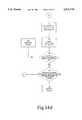
- FIG. 5is a functional block diagram of the portable transmitter
- FIG. 6is a diagram of the signal transmission protocol between the portable transmitter and a slave controller mounted on-board the locomotive;
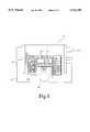
- FIG. 7is a functional block diagram of the slave controller mounted on-board the locomotive.
- FIG. 8is a diagram illustrating the temporal relationship between the signal transmission and the operation of the receiver of the slave controller
- FIG. 9is a diagram illustrating the temporal relationship between signal transmission from two portable transmitters and the operation of the receiver of the slave controller
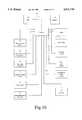
- FIG. 10is a detailed functional block diagram of the slave controller mounted on-board the locomotive;
- FIG. 11is a side elevational view of a velocity sensor for generating a pulse signal whose frequency is correlated to the speed of the locomotive;
- FIG. 12is a side elevational view of the velocity sensor shown in FIG. 11;
- FIG. 13illustrates the pulse output of the velocity sensor shown in FIGS. 11 and 12;
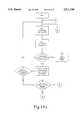
- FIGS. 14a to 14dare a flow charts of the logic implemented to control the speed of the locomotive
- FIGS. 15a and 15bare diagrams illustrating the variation with respect to time of the velocity of the locomotive and of variables used to calculate a throttle or brake correction signal
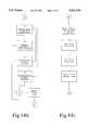
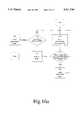
- FIG. 16ais a flow chart illustrating the logic for controlling the speed of the locomotive in a COAST speed setting
- FIG. 16bis a flow chart illustrating the logic for controlling the speed in COAST WITH BRAKE setting
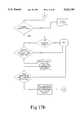
- FIGS. 17a and 17bare flow charts of the logic for transferring the command authority from one remote control transmitter to another.
- FIG. 18is a flow chart of the safety diagnostic routine performed on the braking system of the locomotive.
- the locomotive control system in accordance with the inventionincludes a portable transmitter 10 which generates a digitally encoded radio frequency (RF) signal to convey commands to a slave controller mounted on-board the locomotive.
- the slave controllerdecodes the transmission and operates various actuators on the locomotive to carry into effect the commands remotely issued by the operator.
- RFradio frequency
- FIGS. 1 to 4illustrate the physical layout of the portable transmitter 10.
- the unitcomprises a housing 12 enclosing the electronic circuitry and a battery supplying electric power to operate the system.
- a plurality of manually operable levers and switches projecting outside the housing 12are provided to dial-in locomotive speed, brake and horn settings, among others.
- the various controls on the portable transmitterare defined in the following table:
- the display panel 34On the top surface of the housing 12 is provided a display panel 34 that visually echoes the control settings of the portable transmitter 10.
- the display panel 34includes an array of individual light sources 36, such as light emitting diodes (LED), corresponding to the various operative conditions of the locomotive that can be selected by the operator. Hence, a simple visual observation of the active LED's 36 allows the operator to determine the current position of the controls.
- LEDlight emitting diodes
- FIG. 5provides a functional diagram of the portable transmitter 10.
- the various manually operable switches and levers briefly described aboveare constituted by electric contacts whose state of conduction is altered when the control settings are changed.
- the push-buttons 18, 28, 30 and 32, and the toggle switches 22 and 24have electric contacts that can assume either a closed condition or an opened condition.
- the multi-position levers 14 and 16, and the multi-position switches 20 and 26,have a set of electric contact pairs, only a single pair being closed at each position of the lever or switch. By reading the conduction state of the individual electric contact pairs, the commands issued by the operator can be determined.
- An encoder 38scans at short intervals the state of conduction of each pair of contacts. The scan results allow the encoder to assemble a binary locomotive status word that represent the requested operative state of the locomotive being controlled.
- the following tableprovides the number of bits in the locomotive status word required for each function:
- the locomotive status wordalso contains an identifier segment that uniquely represents the transmitter designated to control the locomotive.
- the purpose of this featureis to ensure that the locomotive will only accept the commands issued by the transmitter generating the proper identifier.
- the encoder 38includes a microprocessor programmed to intelligently assemble the locomotive status word.
- the microprocessorcontinuously scans the electric contacts of the transmitter controls and records their state of conduction.
- the programwill produce the function component of the locomotive status word which is the string of bits that uniquely represents the functions to be performed by the locomotive.
- the programthen appends to the function component the locomotive identifier component and preferably a data security code enabling the receiver on-board the locomotive to check for transmission errors.
- the encodermay be constituted by an array of hardwired logic gates that generate the locomotive status word upon actuation of the controls.
- a transmitter 40receives the locomotive status word and generates an RF signal for transmission of the coded sequence by frequency shift keying.
- the frequency of a carrieris shifted to a first value to signal a logical 1 and to a second value to signal a logical 0.
- the transmission protocolis best shown in FIG. 6.
- Each transmissionbegins with a burst of the carrier frequency 42 for a duration of eight (8) bits (the actual time frame is established on the basis of the transmission baud rate allowed by the equipment).
- Each bit of the data streamis then sent by shifting the frequency to the first or the second value depending on the value of the bit, during a predetermined time slot 44.
- the transmitter 40sends out the locomotive status word in repetition at a fixed rate selected in the range from two (2) to five (5) times per second.
- a fixed rateselected in the range from two (2) to five (5) times per second.
- FIG. 7provides a diagrammatic representation of the slave controller mounted on board the locomotive.
- the slave controller identified comprehensively by the reference numeral 46has three main components, namely a receiver unit 48, a processing unit 50 and a driver unit 52. More particularly, the receiver unit 48 senses the locomotive status word sent out from the portable transmitter 10, decodes the transmission and supplies the resulting binary sequence to the processing unit 50. To achieve a reliable communication link, the receiver 48 is synchronized with the transmitter 40 at three different levels. First, the receiver circuitry defines a signal acceptance window that opens itself at the rate at which the locomotive status word is sent out by the respective controlling transmitter 40. Second, the receiver 48 will observe the frequency value of the transmission in order to decode the binary sequence at intervals precisely corresponding to the time slots 44. Third, the acceptance window opens in phase with the signal transmission.
- the first two levels of synchronizationare established through hardware design, by setting the transmitter 40 and the receiver 48 to the same period of transmission/reception.
- the phasing of the receiver to the incoming locomotive status word transmissionis effected through observation of the burst of carrier frequency 42 that begins each transmission cycle.
- the diagram in FIG. 8graphically illustrates the relationship between the signal transmission and the signal reception.
- the time line 54shows the successive transmission of the locomotive status word as a series of blocks 56.
- the activity of the receiver 48is shown on the time line 58.
- the hatched areascorrespond to the time intervals during which the receiver is not listening.
- the first locomotive status wordis sent out by the transmitter 40.
- the burst of the carrier frequency 42is sensed by the receiver 48 which then activates the sequence of opening and closing of the signal acceptance window which is fully synchronized (in period and phase) with the signal transmission.
- FIG. 9illustrates this feature.
- Time line 60shows the transmission pattern of a first portable transmitter.
- the time line 62depicts the window of acceptance of the companion receiver.
- the receiver 48can, and probably will, correctly receive from time to time a locomotive status word from an unrelated transmitter. This status word will be rejected, however, because the transmitter identifier will not match the value stored in the memory of the slave controller.
- the transmitter/receiver gear of the remote locomotive control systemhas been described above in terms of function of the principal parts of the system and their interaction.
- the components and interconnections of the electric network necessary to carry into effect the desired functionsare not being specified because such details are well within the reach of a man skilled in the art.
- FIG. 10provides a functional diagram of the processing unit 50.
- a central processing unit (CPU) 66communicates with a memory through a bus 70.
- a reserved portion memory 68contains the programm that directs the CPU 66 to control the locomotive depending on the several inputs that will be discussed later.
- the memoryalso contains a section allowing temporary storage of data used by the CPU when handling hardware events.
- the current locomotive status and the commands issued from the remote transmitterare directed to the CPU through an interface 72 communicating with the bus 70.
- the interface 72receives input signals from the following sources:
- a speed direction sensor 74providing locomotive velocity and direction of movement data
- a speed sensor 76providing solely locomotive velocity data.
- the speed sensor 76provides the CPU 66 with redundant velocity data allowing the CPU 66 to detect a possible failure of the main speed sensor 74.
- a pressure sensor 78observing the air pressure in the locomotive brake system
- a pressure sensor 79observing the air pressure in the main reservoir
- a sensor 82observing the flow rate of air in the brake system of the train.
- the structure of the speed/direction sensor 74is illustrated in FIGS. 11 and 12.
- the sensorincludes a disk 84 mounted to an axle 86 of the locomotive. When the locomotive is moving the disk 84 turns at the same angular speed as the axle 86.
- the disk 84is provided with a layer of reflective coating 85 deposited to form on the periphery of the disk equidistant and alternating reflective zones 87 and substantially non-reflective zones 89.
- a pair of opto-electric sensors 92 and 94are mounted in a spaced apart relationship adjacent the periphery of the disk 84.
- the sensor 92comprises an emitter 92a generating a light beam perpendicular to the plane of the disk 84, and a receiver 92b producing an electric signal when sensing the reflection of the light beam on the reflective zones 87.
- a substantially non-reflective surface 89registers with the sensor 92, the output of the receiver is null or very low.
- the structure and operation of the opto-electric sensor 94is identical to the sensor 92.
- the sensor 94comprises an emitter 94a and a receiver 94b.
- the spacing between the opto-electric sensors 92 and 94is such that they generate output pulses due to the periodic change in reflectivity of the disk surface, occurring at different instants in time.
- the sensor 92switches on as a result of a reflective zone 87 registering with the emitter 92a and the receiver 92b, the sensor 94 is still in a stable on condition and can be caused to switch off only by further rotating the disk 84.
- the disk 84 and the sensors 92 and 94are mounted in a hermetically sealed housing to protect the assembly against contamination by water or dirt.
- FIG. 13illustrates the signal waveforms produced by the opto-electric sensors 92 and 94. Both outputs are pulse trains having the same frequency but out of phase by an angle ⁇ which depends upon the spacing of the sensors 92 and 94.
- the pulse train from sensor 94leads the pulse train from sensor 92 by angle ⁇ .
- the output of sensor 92leads the output of sensor 94 by angle ⁇ (this possibility is not shown in FIG. 13).
- the processing unit 50observes the occurrence of the leading pulse edges from the sensors 92 and 94 with relation to time to determine the identity of the leading signal, which allows derivation of the direction of movement of the locomotive.
- Velocity datais derived by measuring the rate of fluctuation of the signal from any one of sensors 92 and 94. It has been found practical to determine the velocity at low locomotive speeds by measuring the period of the signal. However, at higher speeds the frequency of the signal is being measured since the period shortens which may introduce non-negligible measurement errors.
- the speed sensor 76is similar to sensor 74 described above with two exceptions. First, a single opto-electric sensor may be used since all that is required is velocity data. Second, the speed sensor 76 is mounted to a different axle of the locomotive.
- the pressure sensors 78 and 79are switches mounted to the main reservoir and to the pneumatic line that supplies working fluid to the locomotive independent braking mechanism, and produce an electric signal in response to pressure. These sensors merely indicate the presence of pressure, not its magnitude. In essence, each sensor produces an output when the air pressure exceeds a preset level, indicating whether the reserve of compressed air is sufficient for reliable braking. Unlike the sensors 78 and 79, the pressure sensor 80 is a transducer that generates a signal indicative of presence and magnitude of pressure in the train brake air line.
- the airflow sensor 82observes the volume of air circulating in the pneumatic lines of the train brake system. The results of this measurement along with the output of pressure sensor 78 provide an indication of the state of charge of the pneumatic network. It is considered normal for a long pneumatic path to experience some air leaks due primarily to imperfect unions in pipe couplings between cars of the train. However, when a considerable volume of air leaks, the airflow sensor 82 enables the processing unit to sense such condition and to implement corrective measures, as will be discussed later.
- the interface 72receives the signals produced by the sensors 74, 76, 78, 79, 80, and 82 and digitizes them where required so they can be directly processed by the CPU 66.
- the locomotive status word issued by the receiver 48requires no conversion since it is already in the proper binary format.
- the binary signals generated by the CPU 66 that control the various functions of the locomotiveare supplied through the bus 70 and the interface 72.
- the following control signalsare being issued:
- the signalis constituted by one (1) bit, each operative condition of the locomotive lights being represented by a different bit state;
- a five (5) bit signal 102 for traction controlis used to communicate the throttle settings (only eight (8) settings are possible) and one bit for the power contacts of the electric traction motors;
- the interface 72will covert at least some of the signals 98, 100, 102, 104, and 106 from the binary form to a different form that the devices at which the signals are directed can handle. This is described in more detail below.
- the actuators for the lights and bell/hornare merely switches such as relays or solid state devices that energize or de-energize the desired circuit.
- the interface 72in response to the CPU 66 instruction to set the lights/bell/horn in the desired operative position, will generate an electric signal that is amplified by the driver unit 52 and then directed to the respective relay or solid state switch.
- the traction controlit should be noted that most locomotive manufacturers will install on the diesel/electric engine as original equipment a series of actuators that control the fuel injection, power contracts and brakes among others, hence the tractive power that the locomotive develops. This feature permits coupling several locomotives under control of one driver.
- the throttle commands the driver issues in the cab of the mother engineare duplicated in all the slave locomotives.
- the locomotive remote control systemin accordance with the invention makes use of the existing throttle/brake actuators in order to control power.
- the interface 72converts the binary throttle settings issued by the CPU 66 to the standard signal protocol established by the industry for controlling throttle/brake actuators.
- the locomotive remote control systemdoes not require the installation of any throttle/brake actuators.
- the traction control signal 102 incoming from the interface 72is amplified in the driver unit 52 before being directed to the throttle/brake actuators.
- the train brake control signal 104 issued by the interface 72is an eight (8) bit binary sequence applied to a valve mounted in the train brake circuit to modulate the air pressure in the train line that controls the braking mechanism.
- the working fluidis supplied from a main reservoir whose integrity is monitored by the pressure sensor 79 described above.
- the independent locomotive brakeis controlled in the same fashion with binary signal 106.
- the flowchart of the speed control logicis shown in FIGS. 14a to 14d.
- the program executionbegins by reading the velocity data generated from sensors 74 and 76 that are mounted at different axles of the locomotive.
- the data gathered from each sensoris stored in the memory 68 and then compared at step 124. If both sensors are functioning properly they should generate identical or nearly identical velocity values.
- the CPU 66concludes that a malfunction exists and issues a command (step 126) to fully apply the independent brake in order to bring the locomotive to a complete stop.
- the CPU 66will compare the observed locomotive speed with the speed requested by the operator.
- the later variableis represented by a string of three (3) bits in the locomotive status word (the flowchart of FIGS. 14a to 14d assumes that the locomotive status word has been correctly received, has the proper identifer and has been stored in the memory 68).
- the operatorcan select on the portable transmitter 10 eight possible speed settings, each setting being represented by a different binary sequence.
- the speed settingsare as follows:
- the CPU 66will effect a certain number of comparisons at steps 128 and 130 to determine if there is a variation between the actual speed and the selected speed along with the sign of the variation, i.e. whether the locomotive is overspeeding or moving too slowly. More particularly, if at step 128 the CPU 66 determines that the observed speed is in line with the desired speed no corrective measure is taken and the program execution initiates a new cycle. On the other hand, if the actual speed differs from the setting, the conditional test 130 is applied to determine the sign of the difference. Under a negative sign, i.e. the locomotive is moving too slowly, the program execution branches to processing thread A (shown in FIG.
- the CPU 66will determine at step 132 the velocity error by subtracting the actual velocity from the set point contained in the locomotive status word.
- a proportional plus derivative plus integral algorithmis then applied for calculating throttle setting intended for reducing the velocity error to zero.
- the CPU 66will calculate the sum of the integral of the velocity error signal (calculated in step 145), of the derivative of the velocity error signal (calculated in step 147), and of a proportional factor (calculated in step 143). The latter is the velocity error signal multiplied by a predetermined constant. The result of this calculation provides a control signal that is used for modulating the throttle actuator of the locomotive through output signal 102 of the interface 72.
- FIG. 15ais a diagram illustrating the variation of the current velocity signal, the set point, the velocity error, the velocity error integral, the velocity error derivative and velocity error proportional with respect to time.
- step 138the program execution continues to steps 134 and 136 where the current direction of movement and speed of the locomotive are determined from the reading of sensor 74.
- the CPU 66observes a zero speed value for a time period of more than 20 seconds in spite of the fact that a tractive effort is being applied (step 138), it declares a malfunction and fully applies the independent locomotive brake. Normally, when a tractive effort is applied it causes the locomotive to accelerate. The movement, however, may occur after a certain delay following the application of the tractive effort especially if the locomotive is pulling a heavy consist. Still, if after a certain time period no movement is observed, some sort of malfunction is probably present. One possibility is that both sensors 74 and 76 have failed and register zero speed even when the locomotive is rolling. This is highly unlikely but not impossible. When such condition is encountered the CPU 66 immobilizes the locomotive immediately upon determination that a fault is present.
- the 20 seconds waiting period before application of the independent brakeis implemented by verifying the velocity data from sensor 74 during a certain number of program execution cycles. For instance, the current velocity value is compared to the velocity value observed during the previous execution cycle that has been stored in the memory 68. If a change is noted, i.e. the locomotive moves, then the step 138 is considered to have been successively passed. If, however, after 200 execution cycles that require about 20 seconds to be completed, no change with the previously observed velocity value is noted, the independent brake is fully applied.
- step 140the direction of movement of the locomotive read from the output of sensor 74 is compared to the direction of movement specified by the operator. This value is represented by a four (4) bit string in the locomotive status word. If the locomotive is moving rearwardly while the operator has specified a forward movement, the CPU 66 detects a condition known as "rollback". Such condition may occur when the locomotive is starting to move upwardly on a grade while pulling a heavy consist. Under the effect of gravity the train may move backward for a certain distance until the traction system of the locomotive has been able to build-up the pulling force necessary to reverse the movement. During a rollback condition the electric current in the traction motors of the locomotive increase beyond safe levels.
- the programis designed to tolerate a rollback condition for no longer than 20 seconds. If the condition persists beyond this time period the independent brake is fully applied.
- the 20 seconds delayis implemented by comparing the evolution of the results of the comparison step 140 with the results obtained during the previous execution cycle; if the results do not change for 200 program execution cycles that require about 20 seconds of running time on the CPU 66, a fault is declared and the brake applied.
- step 130if the conditional branch points toward processing thread B (see FIGS. 14a and 14c), which means that the locomotive is overspeeding, then the CPU 66 will calculate at step 142 the difference between the selected speed and the observed speed.
- the resulting error signalis then processed by using the proportional plus derivative plus integral algorithm described above to derive a new throttle setting. If by controlling the throttle (reducing the tractive effort developed by the engine) speed correction cannot be achieved, the brake is applied.
- the brakeis modulated by using a proportional plus derivative plus integral algorithm.
- FIG. 15billustrates the brake response, along with the actual brake, error, proportional, derivative, and integral signals with relation to time.
- the calculated brake settingis issued as binary signal 106 (see FIG. 10) that is directed to the braking mechanism on the locomotive.
- the STOP, COAST WITH BRAKE and COAST settingswill now be briefly described.
- the STOP settingintends to bring and maintain the locomotive stationary.
- the CPU 66receives a locomotive status word containing a speed setting corresponding to STOP it immediately terminates the tractive effort and applies the independent locomotive brake at a controlled rate.
- the program logic to implement the COAST and COAST WITH BRAKE servicesis illustrated as flowcharts in FIGS. 16a and 16b, respectively.
- the programreads the velocity data from sensor 74 at step 144 and then compares it at step 146 to the velocity value recorded during the previous program execution cycle. If the consist accelerates under the effect of gravity down a grade (no tractive effort is applied by the system in the COAST and COAST WITH BRAKE settings) the observed velocity will show an increase.
- the CPU 66will then apply the independent locomotive brake to slow the consist at step 148.
- the brakeis modulated by using a proportional plus integral plus derivative (PID) algorithm. In the event that no velocity increase is observed the CPU 66 may set (depending upon the control signal resulting from the PID calculation) the independent brake to the release position at step 150 or keep the brake at the current setting.
- PIDproportional plus integral plus derivative
- the next step in the program executionis a test 152 which determines if the speed of the consist is below 0.5 MPH. In the affirmative the movement is stopped by full application of the independent brake at step 154. If the speed of the consist exceeds or is equal to 0.5 MPH then the program returns to step 144.
- the COAST WITH BRAKE functiondepicted in FIG. 16b is very similar to the COAST service described above. The only difference is that a minimum independent brake pressure of 15 pounds per square inch (psi) is always maintained.
- the acceleration of the consistis determined by comparison of the current velocity with a previous velocity value. If a positive acceleration is observed, such as when the consist moves down a grade, the brake pressure is increased at step 158 (the control is made by a PID algorithm). During the next program execution cycle the acceleration is determined again. If no positive acceleration is sensed the brake pressure is returned to 15 psi at step 160.
- the velocity of the consistis tested against the 0.5 MPH value. If the current speed is less than this limit a full independent brake application is effected in order to stop the consist, otherwise the program execution initiates a new cycle.
- a single operatormay effectively and safely control a consist that includes a limited number of cars remaining at all times well within the visual range of the operator.
- the present inventionprovides a locomotive control system capable of receiving inputs from the selected one of two or more remote transmitters.
- each personis provided with a portable transmitter 10 able to generate the complete range of locomotive control commands.
- the slave controller on-board the locomotivewill accept at any point in time commands from a single designated transmitter. The only exception is a limited set of emergency and signalling commands that are available to both operators.
- the control functioncan be transferred from one transmitter to the other by following the logic depicted in the flowchart of FIGS. 17a and 17b.
- the CPUUpon reception of a locomotive status word, the CPU will compare the identifier in the word to a list of two or more possible identifiers stored in the memory 68.
- the list of acceptable identifierscontains the identifiers of all the remote transmitters permitted to assume control of the locomotive. If the identifier in the locomotive status word does not correspond to any one of the identifiers in the list, then the system rejects the word and takes no action. Otherwise, the system will determine what are the requested functions that the locomotive should perform. If the locomotive status word requests application of the emergency brake or sounding the bell or horn, then the system complies with the request.
- step 179if a new speed setting is requested for example, the system will comply only if the identifier in the locomotive status word matches a specific identifier in the list that designates the remote transmitter currently holding the command authority. If this step is verified, then the locomotive executes the command unless the command is a request to transfer command authority to another remote controller.
- the CPU 66recognizes this request by checking the state of the bit reserved for this function in the locomotive status word. If the state of the bit is 1 (command transfer requested) the program execution continues at step 180 where the CPU 66 will perform a certain number of safety checks to determine if the command transfer can be made in a safe manner. More particularly, the CPU will determine if the locomotive is stopped and if the brake safety checks (to be described later) are verified.
- the CPUwill monitor the reset bit of all the locomotive status words received that carry an identifier in the list stored in the memory 68 (the reset bit issued by the transmitter currently holding the controls is not considered). If within 10 seconds of the reception of the request to transfer control from the current transmitter the CPU observes a reset bit in the high position, which means that the operator of a remote transmitter in the pool of candidates able to acquire control has depressed the reset button, then the CPU 66 shifts in memory the identifier associated with the reset bit at high to the position of the current control holder.
- FIG. 18is a flow chart of a program segment used to identify the state of readiness of the braking system before authorizing movement of the locomotive.
- the CPU 66will check the pressure in the main tank that supplies compressed air to both the independent locomotive and to the train brake. If the pressure is below a preset level, the command to move the locomotive forward is aborted and no action is taken. A second verification step is required to allow movement of a locomotive which is a measurement of the flow rate of compressed air in the train brake line.
- the traction control signal 102is issued only when the compressed air flow rate is below a predetermined level. As briefly discussed earlier, it is normal for a train brake line to exhibit a certain leakage due to imperfect couplings in unions between cars. However, when this leakage exceeds a predetermined level, either there is a major leak or the system is discharged and it is currently being pumped with air. In both cases the train should not be operated for obvious safety reasons.
Landscapes
- Engineering & Computer Science (AREA)
- Mechanical Engineering (AREA)
- Electric Propulsion And Braking For Vehicles (AREA)
- Regulating Braking Force (AREA)
Abstract
Description
______________________________________REFERENCENUMERAL FUNCTION TYPE OF ACTUATOR______________________________________14 Locomotive SpeedMulti-Position Lever Control 16 Locomotive Over- Multi-Position Lever rideBrake Control 18 Reset Push-Button 20 Direction Multi-Position Switch (Forward/Reverse/ Neutral)22 Ring Bell/Horn Toggle Switch 24 Train BrakeToggle Switch Control 26 Power on/Lights Multi-Position Switch Dim/Bright 28 Status Request Pugh-Button 30 Time Extend Push-Button 32 Relinquish Control Push-Button to Companion Portable Transmitter______________________________________
______________________________________NUMBER OF BITS INLOCOMOTIVE STATUSWORD FUNCTION______________________________________3 Locomotive Speed Control3Locomotive Brake Control 1 Reset2 Direction (Forward/Reverse/ Neutral)2 Ring Bell/Horn3Train Brake Control 1 Lights Dim/Bright 1Status Request 1 Time Extend1 Relinquish Control to Companion Portable Transmitter______________________________________
Claims (16)
Priority Applications (5)
| Application Number | Priority Date | Filing Date | Title |
|---|---|---|---|
| US08/221,704US5511749A (en) | 1994-04-01 | 1994-04-01 | Remote control system for a locomotive |
| US08/608,656US5685507A (en) | 1994-04-01 | 1996-02-29 | Remote control system for a locomotive |
| US10/374,590USRE39011E1 (en) | 1994-03-31 | 2003-02-26 | Remote control system for a locomotive |
| US10/374,589USRE39210E1 (en) | 1994-03-31 | 2003-02-26 | Remote control system for a locomotive |
| US11/274,719USRE39758E1 (en) | 1994-03-31 | 2005-11-14 | Remote control system for a locomotive |
Applications Claiming Priority (1)
| Application Number | Priority Date | Filing Date | Title |
|---|---|---|---|
| US08/221,704US5511749A (en) | 1994-04-01 | 1994-04-01 | Remote control system for a locomotive |
Related Parent Applications (1)
| Application Number | Title | Priority Date | Filing Date |
|---|---|---|---|
| US10/374,590ContinuationUSRE39011E1 (en) | 1994-03-31 | 2003-02-26 | Remote control system for a locomotive |
Related Child Applications (3)
| Application Number | Title | Priority Date | Filing Date |
|---|---|---|---|
| US08/608,656DivisionUS5685507A (en) | 1994-03-31 | 1996-02-29 | Remote control system for a locomotive |
| US10/374,590ReissueUSRE39011E1 (en) | 1994-03-31 | 2003-02-26 | Remote control system for a locomotive |
| US11/274,719ReissueUSRE39758E1 (en) | 1994-03-31 | 2005-11-14 | Remote control system for a locomotive |
Publications (1)
| Publication Number | Publication Date |
|---|---|
| US5511749Atrue US5511749A (en) | 1996-04-30 |
Family
ID=22828981
Family Applications (5)
| Application Number | Title | Priority Date | Filing Date |
|---|---|---|---|
| US08/221,704CeasedUS5511749A (en) | 1994-03-31 | 1994-04-01 | Remote control system for a locomotive |
| US08/608,656CeasedUS5685507A (en) | 1994-03-31 | 1996-02-29 | Remote control system for a locomotive |
| US10/374,589Expired - LifetimeUSRE39210E1 (en) | 1994-03-31 | 2003-02-26 | Remote control system for a locomotive |
| US10/374,590Expired - LifetimeUSRE39011E1 (en) | 1994-03-31 | 2003-02-26 | Remote control system for a locomotive |
| US11/274,719Expired - LifetimeUSRE39758E1 (en) | 1994-03-31 | 2005-11-14 | Remote control system for a locomotive |
Family Applications After (4)
| Application Number | Title | Priority Date | Filing Date |
|---|---|---|---|
| US08/608,656CeasedUS5685507A (en) | 1994-03-31 | 1996-02-29 | Remote control system for a locomotive |
| US10/374,589Expired - LifetimeUSRE39210E1 (en) | 1994-03-31 | 2003-02-26 | Remote control system for a locomotive |
| US10/374,590Expired - LifetimeUSRE39011E1 (en) | 1994-03-31 | 2003-02-26 | Remote control system for a locomotive |
| US11/274,719Expired - LifetimeUSRE39758E1 (en) | 1994-03-31 | 2005-11-14 | Remote control system for a locomotive |
Country Status (1)
| Country | Link |
|---|---|
| US (5) | US5511749A (en) |
Cited By (69)
| Publication number | Priority date | Publication date | Assignee | Title |
|---|---|---|---|---|
| US5758848A (en)* | 1994-08-02 | 1998-06-02 | Beule; Erhard | Automatic switching system for track-bound freight cars |
| US5775524A (en)* | 1996-03-25 | 1998-07-07 | Kadee Quality Products Co. | Remote uncoupling mechanism |
| US5866811A (en)* | 1995-07-20 | 1999-02-02 | Westinghouse Air Brake Co. | End of train device |
| WO1999005015A3 (en)* | 1997-07-22 | 1999-04-08 | Tranz Rail Limited | Locomotive remote control system |
| US6092468A (en)* | 1998-03-23 | 2000-07-25 | Daimlerchrysler Ag | Torque controlled mechanism for moving and steering a transit vehicle |
| WO2002018191A1 (en) | 2000-09-01 | 2002-03-07 | Canac Inc. | Remote control system for a locomotive using voice commands |
| US6375276B1 (en)* | 1998-01-28 | 2002-04-23 | Ge-Harris Railway Electronics, Llc | Railway brake system including enhanced pneumatic brake signal detection and associated methods |
| US20020146082A1 (en)* | 1999-03-25 | 2002-10-10 | Canac Inc. | Method and apparatus for assigning addresses to components in a control system |
| US6470245B1 (en)* | 2002-01-31 | 2002-10-22 | Canac Inc. | Remote control system for a locomotive with solid state tilt sensor |
| US6487393B1 (en) | 1999-10-04 | 2002-11-26 | General Electric Company | Method for data exchange with a mobile asset considering communication link quality |
| US20030036368A1 (en)* | 2001-08-17 | 2003-02-20 | Control Chief Corporation | Remote locomotive control |
| US20030097210A1 (en)* | 2000-09-01 | 2003-05-22 | Canac Inc. | Remote control system for a locomotive using voice commands |
| EP1332940A1 (en)* | 2002-01-31 | 2003-08-06 | Canac Inc. | Remote control system for a locomotive with solid state tilt sensor |
| US20030182030A1 (en)* | 2002-03-19 | 2003-09-25 | Kraeling Mark Bradshaw | Automatic coupling of locomotive to railcars |
| US20030178533A1 (en)* | 2002-03-19 | 2003-09-25 | Kornick David F. | Battery change apparatus and method for a locomotive remote control system |
| US20030198298A1 (en)* | 1999-03-25 | 2003-10-23 | Canac, Inc. | [Method and Apparatus for Assigning Addresses to Components in a Control System] |
| US20040073357A1 (en)* | 2000-12-14 | 2004-04-15 | Michael Schliep | Method and system for controlling and/or regulation a load of a vehicle |
| US20040088086A1 (en)* | 2002-10-31 | 2004-05-06 | Canac Inc. | Method and apparatus implementing a communication protocol for use in a control system |
| US20040100938A1 (en)* | 2002-07-31 | 2004-05-27 | Cattron-Theimeg, Inc. | System and method for wireless remote control of locomotives |
| US20040111309A1 (en)* | 1994-09-01 | 2004-06-10 | Matheson William L. | Resource schedule for scheduling rail way train resources |
| US20040117076A1 (en)* | 2002-12-02 | 2004-06-17 | Canac Inc. | Remote control system for locomotives using a TDMA communication protocol |
| US20040117073A1 (en)* | 2002-12-02 | 2004-06-17 | Canac Inc. | Method and apparatus for controlling a locomotive |
| US20040122566A1 (en)* | 2002-12-20 | 2004-06-24 | Canac Inc. | Apparatus and method for providing automated brake pipe testing |
| US20040131112A1 (en)* | 1999-03-30 | 2004-07-08 | Canac Inc. | Method and apparatus for assigning addresses to components in a control system |
| US20040129840A1 (en)* | 2002-12-20 | 2004-07-08 | Folkert Horst | Remote control system for a locomotive |
| US20040183362A1 (en)* | 2003-03-17 | 2004-09-23 | New York Air Brake Corporation | Brake system cut-out control |
| US6834219B2 (en) | 2002-01-31 | 2004-12-21 | Beltpack Corporation | Remote control system for a locomotive with tilt sensor |
| US20050024001A1 (en)* | 2002-02-27 | 2005-02-03 | Donnelly Frank Wegner | Method for monitoring and controlling traction motors in locomotives |
| US6853890B1 (en) | 2003-09-22 | 2005-02-08 | Beltpack Corporation | Programmable remote control system and apparatus for a locomotive |
| US6854691B2 (en) | 2002-02-11 | 2005-02-15 | General Electric Company | Railroad communication system |
| US20050045058A1 (en)* | 2003-08-26 | 2005-03-03 | Donnelly Frank Wegner | Method for monitoring and controlling locomotives |
| US6863247B2 (en) | 2003-05-30 | 2005-03-08 | Beltpack Corporation | Method and apparatus for transmitting signals to a locomotive control device |
| US20050065673A1 (en)* | 2003-09-22 | 2005-03-24 | Canac Inc. | Configurable remote control system for a locomotive |
| US20050075764A1 (en)* | 2003-09-22 | 2005-04-07 | Canac Inc. | Remote control system for a locomotive having user authentication capabilities |
| US20050189886A1 (en)* | 2004-02-17 | 2005-09-01 | Railpower Technologies Corp. | Predicting wheel slip and skid in a locomotive |
| US20050251299A1 (en)* | 2004-03-30 | 2005-11-10 | Railpower Technologies Corp. | Emission management for a hybrid locomotive |
| US20050253022A1 (en)* | 2002-03-19 | 2005-11-17 | Peltz David M | Remotely controlled locomotive car-kicking control |
| US20050269995A1 (en)* | 2004-05-17 | 2005-12-08 | Railpower Technologies Corp. | Design of a Large battery pack for a hybrid locomotive |
| US20050279242A1 (en)* | 2004-03-01 | 2005-12-22 | Railpower Technologies Corp. | Cabless hybrid locomotive |
| US20060005739A1 (en)* | 2001-03-27 | 2006-01-12 | Kumar Ajith K | Railroad system comprising railroad vehicle with energy regeneration |
| US20060005738A1 (en)* | 2001-03-27 | 2006-01-12 | Kumar Ajith K | Railroad vehicle with energy regeneration |
| US20060061307A1 (en)* | 2004-08-09 | 2006-03-23 | Donnelly Frank W | Locomotive power train architecture |
| US20060076171A1 (en)* | 2004-08-09 | 2006-04-13 | Donnelly Frank W | Regenerative braking methods for a hybrid locomotive |
| US20060091832A1 (en)* | 2004-09-03 | 2006-05-04 | Donnelly Frank W | Multiple engine locomotive configuration |
| US7069122B1 (en) | 2002-03-08 | 2006-06-27 | Control Chief Corporation | Remote locomotive control |
| US20060146454A1 (en)* | 2002-11-05 | 2006-07-06 | Donnelly Frank W | Direct turbogenerator |
| US20060247830A1 (en)* | 2005-05-02 | 2006-11-02 | Burke Howard B Jr | Journey event sequencing for automated driverless vehicles |
| US20060266256A1 (en)* | 2005-04-25 | 2006-11-30 | Railpower Technologies Corp. | Multiple prime power source locomotive control |
| US20070120417A1 (en)* | 2005-11-29 | 2007-05-31 | New York Air Brake Corporation | Brake pipe control system with remote radio car |
| US20070142984A1 (en)* | 2005-12-21 | 2007-06-21 | General Electric Company | Protection against exceeding the braking capability of remote controlled locomotives |
| US7236462B2 (en) | 1999-10-04 | 2007-06-26 | General Electric Company | Method for data exchange with a mobile asset considering communication link quality |
| US7236859B2 (en) | 2000-09-01 | 2007-06-26 | Cattron Intellectual Property Corporation | Remote control system for a locomotive |
| US20070144804A1 (en)* | 2005-10-19 | 2007-06-28 | Railpower Technologies, Corp. | Design of a large low maintenance battery pack for a hybrid locomotive |
| US20080077285A1 (en)* | 2004-12-09 | 2008-03-27 | Kumar Ajith K | Methods and Systems for Improved Throttle Control and Coupling Control for Locomotive and Associated Train |
| US20080288131A1 (en)* | 2006-09-14 | 2008-11-20 | New York Air Brake | Method of entry and exit of a remote control mode of a locomotive brake system |
| US20090076664A1 (en)* | 2007-09-13 | 2009-03-19 | Mccabe Paul P | Control system for a pallet truck |
| US20100094483A1 (en)* | 1998-11-04 | 2010-04-15 | Denen Dennis J | Control and motor arrangement for use in model train |
| CN102239703A (en)* | 2008-03-27 | 2011-11-09 | 黑特尼克国际公司 | Remote control system having a touchscreen for controlling a railway vehicle |
| DE102011004130A1 (en)* | 2011-02-15 | 2012-08-16 | Siemens Aktiengesellschaft | Control device and control method |
| US8290646B2 (en) | 2008-03-27 | 2012-10-16 | Hetronic International, Inc. | Remote control system implementing haptic technology for controlling a railway vehicle |
| AU2012238295B2 (en)* | 2012-09-14 | 2014-07-31 | Ge Global Sourcing Llc | Method and apparatus for positioning a rail vehicle or rail vehicle consist |
| US20150134147A1 (en)* | 2012-09-14 | 2015-05-14 | General Electric Company | Method and apparatus for positioning a vehicle |
| US9248825B2 (en) | 2007-05-16 | 2016-02-02 | General Electric Company | Method of operating vehicle and associated system |
| US9296397B2 (en) | 2013-02-27 | 2016-03-29 | Progress Rail Services Corporation | Emergency override system |
| US9321468B2 (en)* | 2014-05-04 | 2016-04-26 | New York Air Brake Llc | Configurable locomotive brake controller |
| US9469310B2 (en) | 2012-10-18 | 2016-10-18 | Wabtec Holding Corp. | System, apparatus, and method for automatically controlling a locomotive |
| US10449973B2 (en) | 2017-01-03 | 2019-10-22 | Laird Technologies, Inc. | Devices, systems, and methods for relaying voice messages to operator control units of remote control locomotives |
| US20230035533A1 (en)* | 2021-07-29 | 2023-02-02 | Transportation Ip Holdings, Llc | Vehicle control system and method |
| US20230030781A1 (en)* | 2021-07-29 | 2023-02-02 | Transportation Ip Holdings, Llc | Vehicle control system and method |
Families Citing this family (55)
| Publication number | Priority date | Publication date | Assignee | Title |
|---|---|---|---|---|
| CA2248526A1 (en)* | 1998-09-25 | 2000-03-25 | Canac Inc. | Method and apparatus for automatic repetition rate assignment in a remote control system |
| US6631873B2 (en)* | 2000-05-12 | 2003-10-14 | Glen T. Fisher | Protection device to prevent train incursions into a forbidden area |
| US6449536B1 (en)* | 2000-07-14 | 2002-09-10 | Canac, Inc. | Remote control system for locomotives |
| CA2313918C (en)* | 2000-07-14 | 2007-01-09 | Canac Inc. | Remote control system for locomotives |
| US20050091593A1 (en)* | 2002-05-10 | 2005-04-28 | General Electric Company | Method and system for coordinated transfer of control of a remote controlled locomotive |
| US6837466B2 (en)* | 2002-05-10 | 2005-01-04 | General Electric Company | Method and system for coordinated transfer of control of a remote controlled locomotive |
| US6862502B2 (en)* | 2002-05-15 | 2005-03-01 | General Electric Company | Intelligent communications, command, and control system for a land-based vehicle |
| US10338580B2 (en) | 2014-10-22 | 2019-07-02 | Ge Global Sourcing Llc | System and method for determining vehicle orientation in a vehicle consist |
| US10464579B2 (en) | 2006-04-17 | 2019-11-05 | Ge Global Sourcing Llc | System and method for automated establishment of a vehicle consist |
| US11358615B2 (en) | 2002-06-04 | 2022-06-14 | Ge Global Sourcing Llc | System and method for determining vehicle orientation in a vehicle consist |
| US20070271078A1 (en)* | 2002-06-25 | 2007-11-22 | New York Air Brake Corporation | Remote Control Locomotive Simulator |
| US7143017B2 (en)* | 2002-06-25 | 2006-11-28 | New York Air Brake Corporation | Remote control locomotive simulator |
| US20040111722A1 (en)* | 2002-12-02 | 2004-06-10 | Canac Inc. | Remote control system for locomotives using a networking arrangement |
| US7076343B2 (en)* | 2003-02-20 | 2006-07-11 | General Electric Company | Portable communications device integrating remote control of rail track switches and movement of a locomotive in a train yard |
| US7117048B2 (en)* | 2003-09-30 | 2006-10-03 | Rockwell Automation Technologies, Inc. | Safety controller with safety response time monitoring |
| US7729818B2 (en)* | 2003-12-09 | 2010-06-01 | General Electric Company | Locomotive remote control system |
| US7783397B2 (en) | 2003-12-22 | 2010-08-24 | General Electric Company | Method and system for providing redundancy in railroad communication equipment |
| US7239943B2 (en)* | 2004-03-22 | 2007-07-03 | General Electric Company | Operator location tracking for remote control rail yard switching |
| US7233844B2 (en)* | 2004-03-22 | 2007-06-19 | General Electric Company | Locomotive remote control system with diagnostic display |
| CN1956870B (en)* | 2004-03-22 | 2010-12-22 | 通用电气公司 | Operator position tracking for remote control of rail yard switching |
| KR20080075164A (en)* | 2005-11-07 | 2008-08-14 | 브룩스 오토메이션 인코퍼레이티드 | Reduced capacity carriers, conveyers, load ports and buffer systems |
| US8272827B2 (en)* | 2005-11-07 | 2012-09-25 | Bufano Michael L | Reduced capacity carrier, transport, load port, buffer system |
| US20080107507A1 (en)* | 2005-11-07 | 2008-05-08 | Bufano Michael L | Reduced capacity carrier, transport, load port, buffer system |
| US8267634B2 (en)* | 2005-11-07 | 2012-09-18 | Brooks Automation, Inc. | Reduced capacity carrier, transport, load port, buffer system |
| US7818101B2 (en)* | 2005-12-30 | 2010-10-19 | Canadian National Railway Company | System and method for computing rail car switching solutions in a switchyard using an iterative method |
| US8060263B2 (en) | 2005-12-30 | 2011-11-15 | Canadian National Railway Company | System and method for forecasting the composition of an outbound train in a switchyard |
| US8055397B2 (en)* | 2005-12-30 | 2011-11-08 | Canadian National Railway Company | System and method for computing rail car switching sequence in a switchyard |
| US7747362B2 (en)* | 2005-12-30 | 2010-06-29 | Canadian National Railway Company | System and method for computing rail car switching solutions by assessing space availability in a classification track on the basis of block pull time |
| US7792616B2 (en)* | 2005-12-30 | 2010-09-07 | Canadian National Railway Company | System and method for computing rail car switching solutions in a switchyard including logic to re-switch cars for block size |
| US20070179688A1 (en)* | 2005-12-30 | 2007-08-02 | Canadian National Railway Company | System and method for computing rail car switching solutions in a switchyard |
| US20070173990A1 (en)* | 2006-01-11 | 2007-07-26 | Smith Eugene A | Traction control for remotely controlled locomotive |
| US7484169B2 (en)* | 2006-02-15 | 2009-01-27 | General Electric Company | Implicit message sequence numbering for locomotive remote control system wireless communications |
| US11332167B2 (en) | 2006-04-17 | 2022-05-17 | Transportation Ip Holdings, Llc | Vehicle communication system |
| US20070247000A1 (en)* | 2006-04-21 | 2007-10-25 | Fugiel Robert V | Portable control device for wireless communication with air brake line airflow manipulating device |
| US20110154893A1 (en)* | 2006-04-21 | 2011-06-30 | Fugiel Robert V | Air brake line airflow control device with wireless controller |
| US7703860B2 (en)* | 2006-09-14 | 2010-04-27 | New York Air Brake Corporation | Remote control brake system and manifold |
| US9120494B2 (en)* | 2006-12-04 | 2015-09-01 | General Electric Company | System, method and computer software code for remotely assisted operation of a railway vehicle system |
| TWI361095B (en)* | 2007-03-23 | 2012-04-01 | Yu Tuan Lee | Remote-controlled motion apparatus with acceleration self-sense and remote control apparatus therefor |
| US8380361B2 (en)* | 2008-06-16 | 2013-02-19 | General Electric Company | System, method, and computer readable memory medium for remotely controlling the movement of a series of connected vehicles |
| US20100258682A1 (en)* | 2009-04-14 | 2010-10-14 | Jeffrey Michael Fries | System and method for interfacing wayside signal device with vehicle control system |
| GB2472495A (en)* | 2009-08-03 | 2011-02-09 | Agilent Technologies Inc | Graphical representation of data from high performance liquid chromatography |
| US8532842B2 (en)* | 2010-11-18 | 2013-09-10 | General Electric Company | System and method for remotely controlling rail vehicles |
| US8649916B2 (en)* | 2011-07-01 | 2014-02-11 | General Electric Company | Control system |
| US9897082B2 (en) | 2011-09-15 | 2018-02-20 | General Electric Company | Air compressor prognostic system |
| KR101727329B1 (en)* | 2011-10-19 | 2017-04-17 | 엘에스산전 주식회사 | An apparatus and method for mesuring velocity of train |
| US20130280095A1 (en) | 2012-04-20 | 2013-10-24 | General Electric Company | Method and system for reciprocating compressor starting |
| US8714494B2 (en)* | 2012-09-10 | 2014-05-06 | Siemens Industry, Inc. | Railway train critical systems having control system redundancy and asymmetric communications capability |
| US9233698B2 (en)* | 2012-09-10 | 2016-01-12 | Siemens Industry, Inc. | Railway safety critical systems with task redundancy and asymmetric communications capability |
| US9145863B2 (en)* | 2013-03-15 | 2015-09-29 | General Electric Company | System and method for controlling automatic shut-off of an engine |
| CN106414214A (en)* | 2014-04-16 | 2017-02-15 | 西门子工业公司 | Railway safety critical systems with task redundancy and asymmetric communications capability |
| JP6285821B2 (en)* | 2014-08-07 | 2018-02-28 | ミネベアミツミ株式会社 | Appliance control device, variable device, illumination control device, and variable illumination device |
| US9517772B1 (en) | 2015-05-27 | 2016-12-13 | Caterpillar Inc. | Electronic speed control for locomotives |
| US11854309B2 (en) | 2021-10-30 | 2023-12-26 | Cattron North America, Inc. | Systems and methods for remotely controlling locomotives with gestures |
| US12109993B2 (en)* | 2022-04-19 | 2024-10-08 | Transportation Ip Holdings, Llc | Vehicle control system and method |
| US11851094B1 (en) | 2022-11-04 | 2023-12-26 | Bnsf Railway Company | Remote engine speed control |
Citations (3)
| Publication number | Priority date | Publication date | Assignee | Title |
|---|---|---|---|---|
| US3687082A (en)* | 1970-09-10 | 1972-08-29 | Avco Corp | Automatic electric power supply and speed control system for automated driverless vehicles |
| US4687258A (en)* | 1985-12-11 | 1987-08-18 | Canadian National Railway Company | Remote control system for a locomotive |
| US5039038A (en)* | 1983-09-14 | 1991-08-13 | Harris Corporation | Railroad communication system |
Family Cites Families (233)
| Publication number | Priority date | Publication date | Assignee | Title |
|---|---|---|---|---|
| US3229086A (en) | 1966-01-11 | Automatic train operation systems | ||
| CA670272A (en) | 1963-09-10 | Westinghouse Air Brake Company | Automatic train operation system | |
| US3227870A (en) | 1966-01-04 | Automatic control for trains and other vehicles | ||
| US3312818A (en) | 1967-04-04 | Speed control system | ||
| US1360150A (en) | 1920-11-23 | And one-thied | ||
| US733035A (en) | 1902-08-22 | 1903-07-07 | Henry M Harding | Means for varying the speed of overhead electric carriers. |
| US1515948A (en) | 1920-01-06 | 1924-11-18 | Jr John Hays Hammond | Toy locomotive |
| US1653172A (en) | 1920-06-11 | 1927-12-20 | Jr John Hays Hammond | Radiocontrol of engine speed |
| US1437637A (en) | 1921-03-01 | 1922-12-05 | Milton S Dunkelberger | Distant electrical control means |
| US1816628A (en) | 1925-04-03 | 1931-07-28 | Frank C Williams | Train stopping and speed controlling mechanism |
| US1765173A (en) | 1928-07-11 | 1930-06-17 | Dean S Morrow | Remote control means for cranes |
| US1788815A (en) | 1930-03-19 | 1931-01-13 | Friedrich A Tubach | Variable-speed gear mechanism |
| US1923499A (en) | 1932-02-24 | 1933-08-22 | Naken William | Automatic train control |
| US1929297A (en) | 1932-05-04 | 1933-10-03 | Gen Electric | Remote control system |
| US2257473A (en) | 1938-04-15 | 1941-09-30 | Marx & Co Louis | Remote control system for toys |
| US2278358A (en) | 1939-12-13 | 1942-03-31 | Marx & Co Louis | Remote control system for toys |
| US2235112A (en) | 1940-02-07 | 1941-03-18 | Sidney S Pulaski | Speed control for vehicles |
| US2331003A (en) | 1941-03-24 | 1943-10-05 | Gilbert Co A C | Remote control circuit |
| US2447669A (en) | 1943-02-08 | 1948-08-24 | Westinghouse Electric Corp | Remote-control system |
| US2576424A (en) | 1945-05-09 | 1951-11-27 | Philco Corp | Automatic speed control for railguided vehicles |
| US2513342A (en) | 1945-08-28 | 1950-07-04 | Us Army | Radio remote-control system |
| US2643369A (en) | 1945-09-28 | 1953-06-23 | Theodore M Manley | Modulated pulse remote control |
| US2709773A (en) | 1945-10-19 | 1955-05-31 | Ivan A Getting | Remote control system with position indicating means |
| US2523662A (en) | 1946-05-31 | 1950-09-26 | Motoview Inc | Remotely controlled photographic apparatus movable along a track |
| US2708885A (en) | 1949-09-14 | 1955-05-24 | Gilbert Co A C | Separate remote control of toy train and carried accessory |
| US2649835A (en) | 1949-09-15 | 1953-08-25 | John T Lierley | Automatic control of the movement of picturemaking equipment |
| US2743678A (en) | 1950-07-11 | 1956-05-01 | Alvin D Wert | Method of and system for the remote control of model railroads |
| US2769601A (en) | 1950-08-18 | 1956-11-06 | Northrop Aircraft Inc | Automatic radio control system |
| US2832426A (en) | 1951-12-20 | 1958-04-29 | William A Seargeant | Teledynamic system for the control of self-propelled vehicles |
| US2768331A (en) | 1954-06-21 | 1956-10-23 | Sperry Rand Corp | Fail-safe speed control system |
| US2780300A (en) | 1955-08-09 | 1957-02-05 | Millard L Beyer | Remote variable control of vehicle speed |
| US2951452A (en) | 1957-04-05 | 1960-09-06 | Gen Railway Signal Co | Remote control system for a trimming locomotive |
| US2948234A (en) | 1957-09-30 | 1960-08-09 | Gen Railway Signal Co | Remote control organization for a locomotive |
| US2993299A (en) | 1958-01-23 | 1961-07-25 | Jr Alexander L M Dingee | Remotely controlled trackless vehicle |
| US2961640A (en) | 1958-06-16 | 1960-11-22 | Westinghouse Air Brake Co | Automatic radio-transmitted brake application and release signalling apparatus for railway trains |
| US3029893A (en) | 1958-08-25 | 1962-04-17 | Gen Motors Corp | Automatic vehicle control system |
| US2998513A (en) | 1959-06-22 | 1961-08-29 | Westinghouse Air Brake Co | Train control system |
| US3072785A (en) | 1960-04-21 | 1963-01-08 | Gen Railway Signal Co | Remote control system for vehicles |
| US3086319A (en) | 1960-04-25 | 1963-04-23 | Gilbert Co A C | Road traffic toy remote controlled |
| US3218454A (en) | 1960-10-24 | 1965-11-16 | Gen Signal Corp | Vehicle control system |
| US3253143A (en) | 1960-12-09 | 1966-05-24 | Gen Signal Corp | Locomotive control system |
| US3096056A (en) | 1961-01-25 | 1963-07-02 | Westinghouse Air Brake Co | Locomotive remote control system |
| US3263625A (en) | 1961-11-29 | 1966-08-02 | Itt | Electrical control systems for point-to-point transit systems |
| US3239962A (en) | 1962-03-29 | 1966-03-15 | Amt Corp | Remotely controlled electrically driven and steered toy vehicle |
| US3201899A (en) | 1962-03-30 | 1965-08-24 | Amt Corp | Remotely controlled toy and track arrangement therefor |
| US3205618A (en) | 1963-06-17 | 1965-09-14 | Heytow Solomon | Remote control system for toy automobiles |
| US3315613A (en) | 1963-07-22 | 1967-04-25 | Leslie Res Co | Remote control for model train system |
| US3293549A (en) | 1963-09-23 | 1966-12-20 | Gen Signal Corp | Radio communication system for control of locomotives |
| US3355643A (en) | 1964-01-28 | 1967-11-28 | Gen Electric | Plural remote controllers for plural motors using a common power connection |
| US3268727A (en) | 1964-03-25 | 1966-08-23 | Gibbs & Hill Inc | Computer control for transit system |
| US3328580A (en) | 1964-07-14 | 1967-06-27 | Westinghouse Air Brake Co | Rapid transit speed control system |
| US3304501A (en) | 1964-08-20 | 1967-02-14 | Motorola Inc | Time delay circuit for briefly holding a selective call transmitter energized |
| US3378817A (en) | 1964-12-09 | 1968-04-16 | Gen Electric | Signalling systems |
| US3380399A (en) | 1965-06-30 | 1968-04-30 | North Electric Co | Remote control and supervision system for a railroad train |
| US3355584A (en) | 1965-10-01 | 1967-11-28 | Westinghouse Air Brake Co | Train speed control system |
| US3368073A (en) | 1965-10-01 | 1968-02-06 | Westinghouse Air Brake Co | Train speed control system |
| US3374035A (en) | 1966-07-01 | 1968-03-19 | Gen Signal Corp | Brake control systems for multiple unit trains |
| US3361082A (en) | 1966-07-11 | 1968-01-02 | Donald J. Leslie | Model train control system |
| FR1493672A (en) | 1966-07-19 | 1967-09-01 | Westinghouse Freins & Signaux | Information transmission system for continuous commands, more particularly usable for remote control of locomotives |
| US3402972A (en) | 1966-08-11 | 1968-09-24 | Gen Electric | Continuous pressure control system |
| US3384033A (en) | 1967-05-25 | 1968-05-21 | Ruff Douglass | Semi-automatic locomotive control system |
| US3530434A (en)* | 1967-06-14 | 1970-09-22 | Sylvania Electric Prod | Coded frequency vehicle identification system |
| US3646613A (en) | 1967-10-31 | 1972-02-29 | Tsubakimoto Chain Co | Automatic carrying system |
| GB1249465A (en) | 1967-11-30 | 1971-10-13 | Emi Ltd | Improvements relating to automatic vehicle guidance systems |
| DE1900786A1 (en) | 1968-01-08 | 1969-09-25 | Takalo Kauko Armas | Remote control system for miniature vehicles |
| US3593293A (en) | 1968-07-01 | 1971-07-13 | Bjorn A Rorholt | Remote control and data logging system |
| US3553449A (en) | 1968-07-01 | 1971-01-05 | Westinghouse Air Brake Co | Central office control circuits for remote control systems |
| US3539226A (en) | 1969-02-10 | 1970-11-10 | Gen Signal Corp | Override-nullifying scheme for train control system |
| US3655962A (en) | 1969-04-01 | 1972-04-11 | Melpar Inc | Digital automatic speed control for railway vehicles |
| US3650216A (en) | 1969-08-11 | 1972-03-21 | Rex Chainbelt Inc | Railway car speed control transportation system |
| US3601605A (en) | 1969-08-28 | 1971-08-24 | Westinghouse Air Brake Co | Cab signal and speed control for locomotives |
| US3583771A (en) | 1969-09-02 | 1971-06-08 | Westinghouse Air Brake Co | Locomotive brake control apparatus suited for remote multiple-unit operation |
| US3696758A (en) | 1969-12-18 | 1972-10-10 | Genisco Technology Corp | Locomotive signaling and control system |
| US3639755A (en) | 1970-01-02 | 1972-02-01 | Gen Signal Corp | Remote control of a locomotive |
| US3628463A (en) | 1970-02-20 | 1971-12-21 | Interlake Steel Corp | Speed-control device |
| US3941202A (en) | 1970-04-30 | 1976-03-02 | Trw Inc. | Digital speed control |
| US3660653A (en) | 1970-06-05 | 1972-05-02 | Pullman Inc | Railroad car speed control mechanism |
| USRE28306E (en) | 1970-09-10 | 1975-01-21 | Automatic electric power supply and speed controlsystem for automated driverless vehicles | |
| DE2052009B2 (en) | 1970-10-23 | 1974-09-12 | Krauss-Maffei Ag, 8000 Muenchen | Arrangement for controlling the pressure in a pressure line, in particular in a brake pressure air line in rail vehicles immediately after a sliding process |
| US3652937A (en) | 1970-11-02 | 1972-03-28 | William L Garrott | Speed and fault indicator for a model vehicle |
| US3694650A (en) | 1970-11-27 | 1972-09-26 | Westinghouse Air Brake Co | Car coupling maximum speed control system |
| GB1384053A (en) | 1971-03-23 | 1975-02-19 | Westinghouse Brake & Signal | Remote control arrangements |
| FR2144061A5 (en) | 1971-06-29 | 1973-02-09 | Matra Engins | |
| US3728565A (en) | 1971-07-21 | 1973-04-17 | Eaton Corp | Device for sensing the direction and speed of a shaft |
| SE388745B (en) | 1971-10-12 | 1976-10-11 | Saab Scania Ab | KIT TO CONTROL FOR DISTANCE MANUFACTURE OF AN OBJECT RECEIVED CONTROL ORDERS AND DEVICE FOR PERFORMANCE OF THE KIT |
| US3840736A (en) | 1971-10-27 | 1974-10-08 | Mitsubishi Electric Corp | Apparatus for controlling vehicles at junction points |
| DE2160494B2 (en) | 1971-12-07 | 1976-04-01 | Krauss-Maffei AG, 8000 München | SLIP AND SLIP PROTECTION DEVICE FOR TRAIN VEHICLES |
| US3819932A (en) | 1972-03-22 | 1974-06-25 | Gen Signal Corp | Multi-computer automatic vehicle control system |
| US3885137A (en) | 1972-05-08 | 1975-05-20 | Aisin Seiki | Method and system for constant-speed running of vehicles |
| US3880088A (en) | 1973-03-26 | 1975-04-29 | Goodyear Tire & Rubber | Vehicle control system and method |
| US3906348A (en)* | 1973-08-20 | 1975-09-16 | Chamberlain Mfg Corp | Digital radio control |
| FR2243836B3 (en) | 1973-09-14 | 1977-06-17 | Siemens Ag | |
| US3879004A (en) | 1973-10-01 | 1975-04-22 | Gen Signal Corp | Vehicle detection, signaling and communication system |
| GB1501372A (en) | 1973-11-27 | 1978-02-15 | Hawker Siddeley Dynamics Ltd | Identifying location of vehicles |
| GB1463761A (en) | 1974-02-08 | 1977-02-09 | London Transport Executive | Speed sensors |
| SE380769B (en) | 1974-03-25 | 1975-11-17 | Philips Svenska Ab | INFORMATION TRANSMISSION SYSTEM FOR TRANSMISSION OF INFORMATION REGARDING DIFFERENT SIGNAL CONDITIONS |
| NL176152C (en) | 1975-01-30 | 1985-03-01 | Estel Hoogovens Bv | RADIO CONTROLLABLE DRIVING LOCOMOTIVE. |
| US4015082A (en) | 1975-03-13 | 1977-03-29 | Westinghouse Electric Corporation | Multi-channel signal decoder |
| US3946972A (en) | 1975-05-08 | 1976-03-30 | Westinghouse Air Brake Company | Simplified cab signal receiver circuit |
| US4005838A (en) | 1975-05-27 | 1977-02-01 | Westinghouse Air Brake Company | Station stop and speed regulation system for trains |
| US4005837A (en) | 1975-05-27 | 1977-02-01 | Westinghouse Air Brake Company | Circuit arrangement for controlling the propulsion, braking and station stopping function for a rapid transit train |
| US3964701A (en) | 1975-05-27 | 1976-06-22 | John Kacerek | Model railroad train control system |
| DE2528463A1 (en) | 1975-06-26 | 1977-01-20 | Knorr Bremse Gmbh | CONTROLLING THE DRIVE AND / OR BRAKE OF TRAIN VEHICLES |
| US4002314A (en) | 1975-07-07 | 1977-01-11 | Westinghouse Electric Corporation | Train vehicle speed control signal providing apparatus |
| GB1565203A (en) | 1975-07-25 | 1980-04-16 | Pico Electronics Ltd | Remote control systems |
| US3994237A (en) | 1975-10-06 | 1976-11-30 | Heath Company | Power supply for realistic control of model railroad engines |
| JPS5264707A (en) | 1975-11-26 | 1977-05-28 | Japanese National Railways<Jnr> | Automatical train stopping control system of point controlling type |
| AU513841B2 (en) | 1975-12-08 | 1981-01-08 | Southern Pacific Transportation Co. | Brake control valve failure location indicator |
| US4041470A (en) | 1976-01-16 | 1977-08-09 | Industrial Solid State Controls, Inc. | Fault monitoring and reporting system for trains |
| US4162486A (en)* | 1976-02-23 | 1979-07-24 | Tre Corporation | Encoded electrical control systems |
| JPS52105406A (en) | 1976-03-02 | 1977-09-03 | Nippon Steel Corp | Speed control system for radio-controlled diesel locomotive |
| US4056286A (en) | 1976-06-08 | 1977-11-01 | Westinghouse Air Brake Company | Remote control brake system for a railway train |
| US4013323A (en) | 1976-06-09 | 1977-03-22 | Westinghouse Air Brake Company | Remote control brake system for a railway train |
| DE2628905C3 (en) | 1976-06-28 | 1978-12-14 | Siemens Ag, 1000 Berlin Und 8000 Muenchen | Train protection and control system |
| DE2633089A1 (en) | 1976-07-22 | 1978-01-26 | Siemens Ag | Automatic selective speed control system for locomotives - has train identification transponders with respective speed encoding and resonant circuits to identify class of locomotive |
| DE2634453A1 (en) | 1976-07-30 | 1978-02-02 | Knorr Bremse Gmbh | TWO-PRESSURE BRAKE CONTROL VALVE FOR A SINGLE-LEVEL SOLVING, INDIRECTLY ACTIVE AIR BRAKE, ESPECIALLY FOR RAIL VEHICLES |
| DE2635751C3 (en) | 1976-08-09 | 1980-02-14 | Siemens Ag, 1000 Berlin Und 8000 Muenchen | Automatic speed control for track-bound vehicles |
| DE2638437C2 (en) | 1976-08-26 | 1985-12-19 | Knorr-Bremse GmbH, 8000 München | Brake accelerator |
| DE2640756C2 (en) | 1976-09-10 | 1982-11-04 | Standard Elektrik Lorenz Ag, 7000 Stuttgart | Device for secure data transmission in track-bound vehicles |
| AU510608B2 (en) | 1976-10-20 | 1980-07-03 | Knorr-Bremse A.G. | Brake accelerator |
| US4665833A (en) | 1976-11-03 | 1987-05-19 | Fleishman Herman B | Miniature electric track and train |
| JPS5364308U (en) | 1976-11-04 | 1978-05-30 | ||
| US4235402A (en) | 1976-12-17 | 1980-11-25 | Westinghouse Electric Corp. | Train vehicle speed control apparatus |
| JPS5922999B2 (en) | 1977-01-25 | 1984-05-30 | 東京電力株式会社 | Conveyance control method using phase pulse signals |
| DE2707047B2 (en) | 1977-02-18 | 1979-08-02 | Siemens Ag, 1000 Berlin Und 8000 Muenchen | Arrangement for detecting the skidding or sliding of the wheels of non-axled rail locomotives |
| DE2708361A1 (en) | 1977-02-23 | 1978-08-31 | Licentia Gmbh | METHOD AND ARRANGEMENT FOR AUTOMATICALLY ACCURATE BRAKING OF RAILWAY VEHICLES |
| US4093161A (en) | 1977-04-25 | 1978-06-06 | General Signal Corporation | Control system with improved communication for centralized control of vehicles |
| US4118774A (en) | 1977-05-16 | 1978-10-03 | Westinghouse Air Brake Company | Locomotive speed control apparatus |
| US4138723A (en) | 1977-08-12 | 1979-02-06 | General Motors Corporation | Motor vehicle speed control system |
| DE2741584C2 (en) | 1977-09-15 | 1986-01-02 | Theimeg-Elektronikgeräte GmbH & Co, 4060 Viersen | Method and device for transmitting command telegrams in time division multiplex on a single high-frequency carrier frequency |
| US4179739A (en) | 1978-02-13 | 1979-12-18 | Virnot Alain D | Memory controlled process for railraod traffic management |
| US4156864A (en) | 1978-02-22 | 1979-05-29 | The Kansas City Southern Railway Co., Inc. | Pressure switch checking device for locomotives |
| DE2824168C3 (en) | 1978-06-02 | 1985-11-14 | Standard Elektrik Lorenz Ag, 7000 Stuttgart | Device for controlling track-bound vehicles in train sets |
| US4209828A (en) | 1978-06-28 | 1980-06-24 | Westinghouse Electric Corp. | Speed decoding and speed error determining control apparatus and method |
| GB2031624B (en) | 1978-08-15 | 1982-03-31 | Rovex Ltd | Remote control of electrical devices |
| DE2840262C3 (en) | 1978-09-15 | 1995-04-20 | Knorr Bremse Ag | Device for controlling pneumatic or electro-pneumatic brakes on rail vehicles |
| DE2848061C2 (en)* | 1978-11-06 | 1986-05-15 | Siemens AG, 1000 Berlin und 8000 München | Wireless electronic remote control method and arrangement for carrying out the method |
| DE2848984A1 (en) | 1978-11-11 | 1980-05-22 | Standard Elektrik Lorenz Ag | Railway network with vehicles supplied with computed speed signals - from traffic and fed to fixed station with store of relevant data fed to cabin with display |
| DE2921860C2 (en) | 1979-05-25 | 1986-07-31 | Licentia Patent-Verwaltungs-Gmbh, 6000 Frankfurt | Device for locating and controlling a track-bound vehicle with linear motor drive |
| DE2925196C2 (en) | 1979-06-22 | 1981-09-17 | Krupp Stahl Ag, 4630 Bochum | Device for remote control of a shunting locomotive |
| GB2054229B (en) | 1979-06-25 | 1983-09-14 | Westinghouse Electric Corp | Vehicle control system |
| JPS5619759U (en) | 1979-07-25 | 1981-02-21 | ||
| US4303215A (en) | 1979-07-30 | 1981-12-01 | Alaine Maire | Device for controlling the stopping of a train |
| DE2943385A1 (en) | 1979-10-26 | 1981-05-07 | Siemens AG, 1000 Berlin und 8000 München | On-board train route information display - uses monitor to indicate route and tachometer to indicate max. speed both supplied from central control |
| US4330830A (en) | 1979-11-27 | 1982-05-18 | Westinghouse Electric Corp. | Transit vehicle control apparatus and method |
| US4331917A (en) | 1979-12-13 | 1982-05-25 | Caterpillar Tractor Co. | Speed and direction sensing circuit |
| US4304001A (en) | 1980-01-24 | 1981-12-01 | Forney Engineering Company | Industrial control system with interconnected remotely located computer control units |
| US4352103A (en) | 1980-01-24 | 1982-09-28 | Forney Engineering Company | Industrial control system |
| US4402082A (en) | 1980-10-31 | 1983-08-30 | Foster Wheeler Energy Corporation | Automatic line termination in distributed industrial process control system |
| US4347563A (en) | 1980-06-16 | 1982-08-31 | Forney Engineering Company | Industrial control system |
| US4349196A (en) | 1980-02-08 | 1982-09-14 | Smith Engineering | Computer control toy track system |
| ZA81888B (en) | 1980-02-13 | 1982-03-31 | Sensory Systems Lab | Electronic identification system |
| US4459668A (en) | 1980-03-31 | 1984-07-10 | Japanese National Railways | Automatic train control device |
| SE421731B (en) | 1980-07-01 | 1982-01-25 | Saab Scania Ab | SET AND DEVICE FOR REMOTE CONTROL OF A VEHICLE OR MOBILE MACHINE |
| DE3026652A1 (en) | 1980-07-14 | 1982-02-11 | Siemens AG, 1000 Berlin und 8000 München | Track bound vehicle energy conservation - using on board monitoring in conjunction with fixed operation centre and station computer |
| US4347569A (en) | 1980-08-12 | 1982-08-31 | General Signal Corporation | Wheel slip system |
| DE3040080C1 (en) | 1980-10-24 | 1987-11-12 | Standard Elektrik Lorenz Ag, 7000 Stuttgart | Device for signal-safe data transmission between a route and vehicles guided on it |
| JPS5776992A (en)* | 1980-10-30 | 1982-05-14 | Sony Corp | Commander for remote control |
| US4344138A (en) | 1980-11-05 | 1982-08-10 | Frasier Cline W | Digital air brake control system |
| US4614274A (en) | 1980-12-08 | 1986-09-30 | Par Systems Corp. | Control system for automatic material handling crane |
| DE3047637A1 (en) | 1980-12-17 | 1982-07-22 | Siemens AG, 1000 Berlin und 8000 München | Train safety device with controlled braking - includes transmitter signalling to approaching train to maintain safe braking distance |
| DE3107938A1 (en) | 1981-03-02 | 1982-09-16 | Siemens AG, 1000 Berlin und 8000 München | DEVICE FOR SPEED DETECTION |
| DE3126383C2 (en) | 1981-07-03 | 1987-07-09 | Siemens AG, 1000 Berlin und 8000 München | Device for transferring data |
| US4445175A (en) | 1981-09-14 | 1984-04-24 | Motorola, Inc. | Supervisory remote control system employing pseudorandom sequence |
| US4495578A (en) | 1981-10-22 | 1985-01-22 | General Signal Corporation | Microprocessor based over/under speed governor |
| DE3208819A1 (en) | 1982-03-11 | 1983-09-22 | Steuerungstechnik GmbH, 8000 München | Driving and brake control for a locomotive remote-control radio transmitter |
| CA1197597A (en) | 1982-03-11 | 1985-12-03 | John A.I. Young | Wheel slip control using differential signal |
| US4486839A (en) | 1982-08-12 | 1984-12-04 | American Standard Inc. | Synchronous wheel-slip protection system |
| JPS5932008A (en) | 1982-08-17 | 1984-02-21 | Kawasaki Heavy Ind Ltd | Vehicle stop position detection method |
| US4525011A (en) | 1982-09-20 | 1985-06-25 | American Standard Inc. | Vigilance safety control system |
| US4475159A (en) | 1982-12-27 | 1984-10-02 | Robert Bosch Gmbh | Method of storing vehicle operating condition parameters |
| DE3490118C1 (en) | 1983-03-14 | 1994-07-21 | Adcount Ltd | Method for transmitting signals from a ground station to a rail vehicle |
| FR2542951B1 (en) | 1983-03-18 | 1990-03-02 | Alsthom Atlantique | TRACK SAFETY INFORMATION ENCODING SYSTEM FOR TRAINS FOR THEIR CONTROL |
| DE3314714A1 (en) | 1983-04-22 | 1984-10-25 | Gebr. Märklin & Cie GmbH, 7320 Göppingen | CONTROL UNIT FOR MODEL VEHICLES, HOW MODEL RAILWAYS, MODEL CARS, ETC. |
| US4487060A (en) | 1983-05-18 | 1984-12-11 | Glenayre Electronis, Ltd. | Railway brake pressure monitor |
| DE3323269A1 (en) | 1983-06-28 | 1985-01-10 | Siemens AG, 1000 Berlin und 8000 München | DEVICE FOR THE OPERATION OF A COMPUTER-CONTROLLED ACTUATOR |
| EP0132467A1 (en) | 1983-07-28 | 1985-02-13 | Dragan Bukatarevic | A control system for an electrically driven vehicle |
| US4620280A (en) | 1983-07-29 | 1986-10-28 | Si Handling Systems, Inc. | Intelligent driverless vehicle |
| US4498016A (en) | 1983-08-04 | 1985-02-05 | Caterpillar Tractor Co. | Locomotive governor control |
| US4513604A (en) | 1983-08-24 | 1985-04-30 | Frantz Virgil L | Method and apparatus for indicating leakage in compressed air line |
| JPS6056639A (en) | 1983-09-09 | 1985-04-02 | Aisin Seiki Co Ltd | Constant-speed traveling apparatus |
| US4553723A (en) | 1983-09-15 | 1985-11-19 | Harris Corporation | Railroad air brake system |
| EP0141157B1 (en) | 1983-09-28 | 1987-08-26 | BBC Brown Boveri AG | Slip limitation control for rail vehicles |
| GB8332919D0 (en) | 1983-12-09 | 1984-01-18 | Westinghouse Brake & Signal | Vehicle control system |
| US4654881A (en) | 1984-01-04 | 1987-03-31 | Motorola, Inc. | Remote control system having symmetrical tone, send/receive signaling circuits for radio communications |
| GB2159995B (en) | 1984-06-01 | 1987-10-28 | Gec Avionics | Vehicle detection system |
| US4710880A (en) | 1984-11-28 | 1987-12-01 | Westinghouse Electric Corp. | Vehicle speed control apparatus and method |
| JPS61110675U (en) | 1984-12-25 | 1986-07-12 | ||
| DE3512387A1 (en) | 1985-02-12 | 1986-08-14 | Büro Patent AG, Glarus | Conveying installation with self-propelled rail-borne conveying trolleys |
| DE3540563A1 (en) | 1985-11-15 | 1987-12-03 | Krauss Maffei Ag | Arrangement for controlling a drive for rail power units |
| US4621833A (en) | 1985-12-16 | 1986-11-11 | Ford Motor Company | Control system for multistable suspension unit |
| CA1245744A (en) | 1985-12-16 | 1988-11-29 | George W. Astley | Remote control system for a locomotive |
| GB8602509D0 (en) | 1986-02-01 | 1986-03-05 | Westinghouse Brake & Signal | Automatic train operation |
| US4726299A (en) | 1986-02-20 | 1988-02-23 | Regents Of The University Of Minnesota | Method and apparatus for controlling a vehicle |
| HU193852B (en) | 1986-03-28 | 1987-12-28 | Magyar Allamvasutak | Railway-service data processing and car informing system |
| US4733740A (en) | 1986-05-06 | 1988-03-29 | Custom Technologies, Inc. | Automated guided vehicle system |
| US4775116A (en) | 1986-09-02 | 1988-10-04 | Klein David S | Control of craft under high-G pilot stress |
| US4872195A (en) | 1986-11-13 | 1989-10-03 | Gentner Electronics Corporation | Remote control unit for radio/television transmitter station |
| DE3702527A1 (en) | 1987-01-28 | 1988-08-11 | Siemens Ag | Data transmission device with repetition of data telegrams to be transmitted |
| US4893240A (en) | 1987-01-29 | 1990-01-09 | Imad Karkouti | Remote control system for operating selected functions of a vehicle |
| US4854529A (en) | 1987-04-10 | 1989-08-08 | Tsubakimoto Chain Co. | Vehicle control system having two trackside signal lines |
| US4793088A (en) | 1987-05-15 | 1988-12-27 | Fortuna Joseph J | Multiple remote controlled down rigger and planing board system |
| JPH0423734Y2 (en) | 1987-06-12 | 1992-06-03 | ||
| US5109543A (en) | 1987-08-14 | 1992-04-28 | General Electric Company | Hardware interface and protocol for a mobile radio transceiver |
| US4791254A (en) | 1987-12-09 | 1988-12-13 | Hydrolevel Company | Flow switch |
| EP0326630B1 (en) | 1988-02-02 | 1992-06-03 | Theimeg Elektronikgeräte GmbH & Co. KG | Method for transmitting remote control signals on a single carrier frequency between autonomous transmitters and receivers in time multiplexe and arrangement for realization of this method |
| JPH0539754Y2 (en) | 1988-08-05 | 1993-10-08 | ||
| US5065963A (en) | 1988-09-01 | 1991-11-19 | Daifuku Co., Ltd. | Transporting train travel control system |
| US4896090A (en) | 1988-10-31 | 1990-01-23 | General Electric Company | Locomotive wheelslip control system |
| US5029532A (en) | 1988-12-22 | 1991-07-09 | Snead Edwin De S | Control cab |
| US5012749A (en) | 1988-12-27 | 1991-05-07 | The Allen Group Inc. | Radio controlled material handling apparatus |
| DE3902076C1 (en) | 1989-01-25 | 1990-08-23 | Messerschmitt-Boelkow-Blohm Gmbh, 8012 Ottobrunn, De | |
| US4950964A (en) | 1989-04-13 | 1990-08-21 | Caterpillar Inc. | Locomotive differential wheel slip control |
| US5005014A (en) | 1989-05-22 | 1991-04-02 | Motorola, Inc. | System and method for optimally transmitting acknowledge back responses |
| US4955304A (en) | 1989-05-25 | 1990-09-11 | General Motors Corporation | Remote locomotive spotter control |
| JPH0810345Y2 (en) | 1989-08-24 | 1996-03-29 | 株式会社トミー | Orbital toy |
| JPH03104769A (en) | 1989-09-20 | 1991-05-01 | Hitachi Ltd | Car drive manipulating device |
| US5249125A (en) | 1989-12-08 | 1993-09-28 | Knorr Brake Holding Corporation | Computer controlled railway brake equipment |
| US5172316A (en) | 1989-12-08 | 1992-12-15 | New York Air Brake | Computer controlled railway brake equipment |
| US5590042A (en) | 1989-12-08 | 1996-12-31 | New York Air Brake Corporation | Independent brake control |
| JPH0750117B2 (en) | 1990-01-18 | 1995-05-31 | 株式会社椿本チエイン | Vehicle speed control method and speed control device |
| US5284097A (en)* | 1990-10-31 | 1994-02-08 | Loram Maintenance Of Way, Inc. | Ballast distribution, regulation and reclaiming railroad maintenance device |
| JPH04223505A (en) | 1990-12-25 | 1992-08-13 | Makome Kenkyusho:Kk | Magnetic guidance apparatus |
| JP2992357B2 (en) | 1991-02-20 | 1999-12-20 | 株式会社日立製作所 | Vehicle motion characteristic correction device |
| US5408411A (en) | 1991-01-18 | 1995-04-18 | Hitachi, Ltd. | System for predicting behavior of automotive vehicle and for controlling vehicular behavior based thereon |
| US5188038A (en) | 1991-02-11 | 1993-02-23 | Shanley Thomas E | Railroad car derailment safety device |
| FR2672559B1 (en) | 1991-02-12 | 1993-05-28 | Aerospatiale | BRAKING SYSTEM FOR A WHEEL VEHICLE. |
| JP2690220B2 (en) | 1991-02-28 | 1997-12-10 | 三菱電機株式会社 | Train fixed position stop control device |
| US5251856C1 (en) | 1992-02-11 | 2001-07-10 | Liontech Company | Model train controller for reversing unit |
| US5264789A (en) | 1992-07-27 | 1993-11-23 | Eaton Corporation | Method of determining the direction of rotation of a member using a rotor having a predetermined pattern of exciter surfaces |
| US5376869A (en) | 1993-02-11 | 1994-12-27 | General Electric Company | Electric vehicle drive train with rollback detection and compensation |
| JP3360865B2 (en) | 1993-03-26 | 2003-01-07 | 東海旅客鉄道株式会社 | Train speed control method and device |
| US5479156A (en)* | 1994-12-20 | 1995-12-26 | Magnadyne Corporation | Vehicle security system responsive to short and long range transmitters |
- 1994
- 1994-04-01USUS08/221,704patent/US5511749A/ennot_activeCeased
- 1996
- 1996-02-29USUS08/608,656patent/US5685507A/ennot_activeCeased
- 2003
- 2003-02-26USUS10/374,589patent/USRE39210E1/ennot_activeExpired - Lifetime
- 2003-02-26USUS10/374,590patent/USRE39011E1/ennot_activeExpired - Lifetime
- 2005
- 2005-11-14USUS11/274,719patent/USRE39758E1/ennot_activeExpired - Lifetime
Patent Citations (3)
| Publication number | Priority date | Publication date | Assignee | Title |
|---|---|---|---|---|
| US3687082A (en)* | 1970-09-10 | 1972-08-29 | Avco Corp | Automatic electric power supply and speed control system for automated driverless vehicles |
| US5039038A (en)* | 1983-09-14 | 1991-08-13 | Harris Corporation | Railroad communication system |
| US4687258A (en)* | 1985-12-11 | 1987-08-18 | Canadian National Railway Company | Remote control system for a locomotive |
Non-Patent Citations (2)
| Title |
|---|
| LCS BP Presentation, "locomotive Control System Symington Yard," Sep., 1991 (pp. 1-15). |
| LCS BP Presentation, locomotive Control System Symington Yard, Sep., 1991 (pp. 1 15).* |
Cited By (125)
| Publication number | Priority date | Publication date | Assignee | Title |
|---|---|---|---|---|
| US5758848A (en)* | 1994-08-02 | 1998-06-02 | Beule; Erhard | Automatic switching system for track-bound freight cars |
| US7222083B2 (en)* | 1994-09-01 | 2007-05-22 | Harris Corporation | Resource schedule for scheduling rail way train resources |
| US20040111309A1 (en)* | 1994-09-01 | 2004-06-10 | Matheson William L. | Resource schedule for scheduling rail way train resources |
| US5866811A (en)* | 1995-07-20 | 1999-02-02 | Westinghouse Air Brake Co. | End of train device |
| US5775524A (en)* | 1996-03-25 | 1998-07-07 | Kadee Quality Products Co. | Remote uncoupling mechanism |
| WO1999005015A3 (en)* | 1997-07-22 | 1999-04-08 | Tranz Rail Limited | Locomotive remote control system |
| AU733254B2 (en)* | 1997-07-22 | 2001-05-10 | Tranz Rail Limited | Locomotive remote control system |
| US6375276B1 (en)* | 1998-01-28 | 2002-04-23 | Ge-Harris Railway Electronics, Llc | Railway brake system including enhanced pneumatic brake signal detection and associated methods |
| US6092468A (en)* | 1998-03-23 | 2000-07-25 | Daimlerchrysler Ag | Torque controlled mechanism for moving and steering a transit vehicle |
| US20100094483A1 (en)* | 1998-11-04 | 2010-04-15 | Denen Dennis J | Control and motor arrangement for use in model train |
| US7880414B2 (en)* | 1998-11-04 | 2011-02-01 | Lionel L.L.C. | Control and motor arrangement for use in model train |
| US6975927B2 (en) | 1999-03-25 | 2005-12-13 | Beltpack Corporation | Remote control system for locomotive with address exchange capability |
| US20060239379A1 (en)* | 1999-03-25 | 2006-10-26 | Canac Inc. | Method and apparatus for assigning addresses to components in a control system |
| US20020146082A1 (en)* | 1999-03-25 | 2002-10-10 | Canac Inc. | Method and apparatus for assigning addresses to components in a control system |
| US20020152008A1 (en)* | 1999-03-25 | 2002-10-17 | Canac Inc. | Method and apparatus for assigning addresses to components in a control system |
| US7167510B2 (en) | 1999-03-25 | 2007-01-23 | Cattron Intellectual Property Corporation | Method and apparatus for assigning addresses to components in a control system |
| US7164709B2 (en) | 1999-03-25 | 2007-01-16 | Cattron Intellectual Property Corporation | Method and apparatus for assigning addresses to components in a control system |
| US7126985B2 (en) | 1999-03-25 | 2006-10-24 | Cattron Intellectual Property Corporation | Method and apparatus for assigning addresses to components in a control system |
| US20030195671A2 (en)* | 1999-03-25 | 2003-10-16 | Canac Inc | [Method and Apparatus for Assigning Addresses to Components in a Control System] |
| US20030198298A1 (en)* | 1999-03-25 | 2003-10-23 | Canac, Inc. | [Method and Apparatus for Assigning Addresses to Components in a Control System] |
| US20030202621A2 (en)* | 1999-03-25 | 2003-10-30 | Canac Corporation | [Method and Apparatus for Assigning Addresses to Components in a Control System] |
| US7203228B2 (en) | 1999-03-30 | 2007-04-10 | Cattron Intellectual Property Corporation | Method and apparatus for assigning addresses to components in a control system |
| US20040131112A1 (en)* | 1999-03-30 | 2004-07-08 | Canac Inc. | Method and apparatus for assigning addresses to components in a control system |
| US6487393B1 (en) | 1999-10-04 | 2002-11-26 | General Electric Company | Method for data exchange with a mobile asset considering communication link quality |
| US7236462B2 (en) | 1999-10-04 | 2007-06-26 | General Electric Company | Method for data exchange with a mobile asset considering communication link quality |
| US6697716B2 (en) | 2000-09-01 | 2004-02-24 | Canac Inc. | Remote control system for a locomotive using voice commands |
| US6799098B2 (en)* | 2000-09-01 | 2004-09-28 | Beltpack Corporation | Remote control system for a locomotive using voice commands |
| US20030097210A1 (en)* | 2000-09-01 | 2003-05-22 | Canac Inc. | Remote control system for a locomotive using voice commands |
| US6466847B1 (en) | 2000-09-01 | 2002-10-15 | Canac Inc | Remote control system for a locomotive using voice commands |
| WO2002018191A1 (en) | 2000-09-01 | 2002-03-07 | Canac Inc. | Remote control system for a locomotive using voice commands |
| US7236859B2 (en) | 2000-09-01 | 2007-06-26 | Cattron Intellectual Property Corporation | Remote control system for a locomotive |
| US20040073357A1 (en)* | 2000-12-14 | 2004-04-15 | Michael Schliep | Method and system for controlling and/or regulation a load of a vehicle |
| US20060005739A1 (en)* | 2001-03-27 | 2006-01-12 | Kumar Ajith K | Railroad system comprising railroad vehicle with energy regeneration |
| US20060005738A1 (en)* | 2001-03-27 | 2006-01-12 | Kumar Ajith K | Railroad vehicle with energy regeneration |
| US20030036368A1 (en)* | 2001-08-17 | 2003-02-20 | Control Chief Corporation | Remote locomotive control |
| US7120428B2 (en) | 2001-08-17 | 2006-10-10 | Control Chief Corporation | Remote locomotive control |
| US6691005B2 (en) | 2002-01-31 | 2004-02-10 | Canac Inc. | Remote control system for a locomotive with solid state tilt sensor |
| US6834219B2 (en) | 2002-01-31 | 2004-12-21 | Beltpack Corporation | Remote control system for a locomotive with tilt sensor |
| US6470245B1 (en)* | 2002-01-31 | 2002-10-22 | Canac Inc. | Remote control system for a locomotive with solid state tilt sensor |
| EP1332940A1 (en)* | 2002-01-31 | 2003-08-06 | Canac Inc. | Remote control system for a locomotive with solid state tilt sensor |
| US6854691B2 (en) | 2002-02-11 | 2005-02-15 | General Electric Company | Railroad communication system |
| US20050024001A1 (en)* | 2002-02-27 | 2005-02-03 | Donnelly Frank Wegner | Method for monitoring and controlling traction motors in locomotives |
| US6984946B2 (en) | 2002-02-27 | 2006-01-10 | Railpower Technologies Corp. | Method for monitoring and controlling traction motors in locomotives |
| US20050264245A1 (en)* | 2002-02-27 | 2005-12-01 | Railpower Technologies Corp. | Method for monitoring and controlling traction motors in locomotives |
| US7069122B1 (en) | 2002-03-08 | 2006-06-27 | Control Chief Corporation | Remote locomotive control |
| US7177732B2 (en)* | 2002-03-19 | 2007-02-13 | General Electric Company | Automatic coupling of locomotive to railcars |
| US20050253022A1 (en)* | 2002-03-19 | 2005-11-17 | Peltz David M | Remotely controlled locomotive car-kicking control |
| US20030178533A1 (en)* | 2002-03-19 | 2003-09-25 | Kornick David F. | Battery change apparatus and method for a locomotive remote control system |
| US20030182030A1 (en)* | 2002-03-19 | 2003-09-25 | Kraeling Mark Bradshaw | Automatic coupling of locomotive to railcars |
| US7520472B2 (en)* | 2002-03-19 | 2009-04-21 | General Electric Company | Remotely controlled locomotive car-kicking control |
| US20040100938A1 (en)* | 2002-07-31 | 2004-05-27 | Cattron-Theimeg, Inc. | System and method for wireless remote control of locomotives |
| US7529201B2 (en) | 2002-07-31 | 2009-05-05 | Cattron-Theimeg, Inc. | System and method for wireless remote control of locomotives |
| US20040114631A1 (en)* | 2002-07-31 | 2004-06-17 | Cattron-Theimeg, Inc. | System and method for wireless remote control of locomotives |
| US7792089B2 (en) | 2002-07-31 | 2010-09-07 | Cattron-Theimeg, Inc. | System and method for wireless remote control of locomotives |
| US20040120305A1 (en)* | 2002-07-31 | 2004-06-24 | Aiken Robert C. | System and method for wireless remote control of locomotives |
| US7535865B2 (en) | 2002-07-31 | 2009-05-19 | Cattron-Theimeg, Inc. | System and method for wireless remote control of locomotives |
| US20040088086A1 (en)* | 2002-10-31 | 2004-05-06 | Canac Inc. | Method and apparatus implementing a communication protocol for use in a control system |
| US6928342B2 (en) | 2002-10-31 | 2005-08-09 | Beltpack Corporation | Method and apparatus implementing a communication protocol for use in a control system |
| US20060146454A1 (en)* | 2002-11-05 | 2006-07-06 | Donnelly Frank W | Direct turbogenerator |
| US20040117073A1 (en)* | 2002-12-02 | 2004-06-17 | Canac Inc. | Method and apparatus for controlling a locomotive |
| US20040117076A1 (en)* | 2002-12-02 | 2004-06-17 | Canac Inc. | Remote control system for locomotives using a TDMA communication protocol |
| US20040129840A1 (en)* | 2002-12-20 | 2004-07-08 | Folkert Horst | Remote control system for a locomotive |
| US20040122566A1 (en)* | 2002-12-20 | 2004-06-24 | Canac Inc. | Apparatus and method for providing automated brake pipe testing |
| US6964456B2 (en) | 2003-03-17 | 2005-11-15 | New York Air Brake Corporation | Brake system cut-out control |
| US20040183362A1 (en)* | 2003-03-17 | 2004-09-23 | New York Air Brake Corporation | Brake system cut-out control |
| US6863247B2 (en) | 2003-05-30 | 2005-03-08 | Beltpack Corporation | Method and apparatus for transmitting signals to a locomotive control device |
| US7124691B2 (en) | 2003-08-26 | 2006-10-24 | Railpower Technologies Corp. | Method for monitoring and controlling locomotives |
| US20050045058A1 (en)* | 2003-08-26 | 2005-03-03 | Donnelly Frank Wegner | Method for monitoring and controlling locomotives |
| US20050075764A1 (en)* | 2003-09-22 | 2005-04-07 | Canac Inc. | Remote control system for a locomotive having user authentication capabilities |
| US6853890B1 (en) | 2003-09-22 | 2005-02-08 | Beltpack Corporation | Programmable remote control system and apparatus for a locomotive |
| US20050065673A1 (en)* | 2003-09-22 | 2005-03-24 | Canac Inc. | Configurable remote control system for a locomotive |
| US7084602B2 (en) | 2004-02-17 | 2006-08-01 | Railpower Technologies Corp. | Predicting wheel slip and skid in a locomotive |
| US7064507B2 (en) | 2004-02-17 | 2006-06-20 | Railpower Technologies Corp. | Managing wheel skid in a locomotive |
| US20050206230A1 (en)* | 2004-02-17 | 2005-09-22 | Railpower Technologies Corp. | Managing wheel slip in a locomotive |
| US20050189886A1 (en)* | 2004-02-17 | 2005-09-01 | Railpower Technologies Corp. | Predicting wheel slip and skid in a locomotive |
| US7467830B2 (en) | 2004-02-17 | 2008-12-23 | Railpower Technologies Corp. | Managing wheel slip in a locomotive |
| US20050279242A1 (en)* | 2004-03-01 | 2005-12-22 | Railpower Technologies Corp. | Cabless hybrid locomotive |
| US20050251299A1 (en)* | 2004-03-30 | 2005-11-10 | Railpower Technologies Corp. | Emission management for a hybrid locomotive |
| US7349797B2 (en) | 2004-03-30 | 2008-03-25 | Railpower Technologies Corp | Emission management for a hybrid locomotive |
| US20060012334A1 (en)* | 2004-05-17 | 2006-01-19 | Railpower Technologies Corp. | Automated battery cell shunt bypass |
| US7507500B2 (en) | 2004-05-17 | 2009-03-24 | Railpower Technologies Corp. | Design of a large battery pack for a hybrid locomotive |
| US20050269995A1 (en)* | 2004-05-17 | 2005-12-08 | Railpower Technologies Corp. | Design of a Large battery pack for a hybrid locomotive |
| US20060061307A1 (en)* | 2004-08-09 | 2006-03-23 | Donnelly Frank W | Locomotive power train architecture |
| US7304445B2 (en) | 2004-08-09 | 2007-12-04 | Railpower Technologies Corp. | Locomotive power train architecture |
| US20060076171A1 (en)* | 2004-08-09 | 2006-04-13 | Donnelly Frank W | Regenerative braking methods for a hybrid locomotive |
| US7940016B2 (en) | 2004-08-09 | 2011-05-10 | Railpower, Llc | Regenerative braking methods for a hybrid locomotive |
| US20060091832A1 (en)* | 2004-09-03 | 2006-05-04 | Donnelly Frank W | Multiple engine locomotive configuration |
| US7565867B2 (en) | 2004-09-03 | 2009-07-28 | Frank Wegner Donnelly | Multiple engine locomotive configuration |
| US8280569B2 (en)* | 2004-12-09 | 2012-10-02 | General Electric Company | Methods and systems for improved throttle control and coupling control for locomotive and associated train |
| US20080077285A1 (en)* | 2004-12-09 | 2008-03-27 | Kumar Ajith K | Methods and Systems for Improved Throttle Control and Coupling Control for Locomotive and Associated Train |
| US7514807B2 (en) | 2005-04-25 | 2009-04-07 | Railpower Technologies Corp. | Alternator boost method |
| US20060266044A1 (en)* | 2005-04-25 | 2006-11-30 | Frank Donnelly | Alternator boost method |
| US7518254B2 (en) | 2005-04-25 | 2009-04-14 | Railpower Technologies Corporation | Multiple prime power source locomotive control |
| US7309929B2 (en) | 2005-04-25 | 2007-12-18 | Railpower Technologies Corporation | Locomotive engine start method |
| US20060266256A1 (en)* | 2005-04-25 | 2006-11-30 | Railpower Technologies Corp. | Multiple prime power source locomotive control |
| US20060247830A1 (en)* | 2005-05-02 | 2006-11-02 | Burke Howard B Jr | Journey event sequencing for automated driverless vehicles |
| US7142957B2 (en)* | 2005-05-02 | 2006-11-28 | Hbb Assets, Ltd. | Journey event sequencing for automated driverless vehicles |
| US20070144804A1 (en)* | 2005-10-19 | 2007-06-28 | Railpower Technologies, Corp. | Design of a large low maintenance battery pack for a hybrid locomotive |
| US7661370B2 (en) | 2005-10-19 | 2010-02-16 | Railpower, Llc | Design of a large low maintenance battery pack for a hybrid locomotive |
| US20070120417A1 (en)* | 2005-11-29 | 2007-05-31 | New York Air Brake Corporation | Brake pipe control system with remote radio car |
| US7455370B2 (en) | 2005-11-29 | 2008-11-25 | New York Air Brake Corporation | Brake pipe control system with remote radio car |
| US20070142984A1 (en)* | 2005-12-21 | 2007-06-21 | General Electric Company | Protection against exceeding the braking capability of remote controlled locomotives |
| US8311689B2 (en)* | 2005-12-21 | 2012-11-13 | General Electric Company | Protection against exceeding the braking capability of remote controlled locomotives |
| US20080288131A1 (en)* | 2006-09-14 | 2008-11-20 | New York Air Brake | Method of entry and exit of a remote control mode of a locomotive brake system |
| US9248825B2 (en) | 2007-05-16 | 2016-02-02 | General Electric Company | Method of operating vehicle and associated system |
| US20090076664A1 (en)* | 2007-09-13 | 2009-03-19 | Mccabe Paul P | Control system for a pallet truck |
| US8195366B2 (en) | 2007-09-13 | 2012-06-05 | The Raymond Corporation | Control system for a pallet truck |
| US8290646B2 (en) | 2008-03-27 | 2012-10-16 | Hetronic International, Inc. | Remote control system implementing haptic technology for controlling a railway vehicle |
| CN102239703B (en)* | 2008-03-27 | 2015-09-09 | 黑特尼克国际公司 | For controlling the tele-control system with touch-screen of rolling stock |
| CN102239703A (en)* | 2008-03-27 | 2011-11-09 | 黑特尼克国际公司 | Remote control system having a touchscreen for controlling a railway vehicle |
| US8380363B2 (en) | 2008-03-27 | 2013-02-19 | Hetronic International, Inc. | Remote control system having a touchscreen for controlling a railway vehicle |
| US8483887B2 (en) | 2008-03-27 | 2013-07-09 | Hetronic International, Inc. | Remote control system having a touchscreen for controlling a railway vehicle |
| US8509964B2 (en) | 2008-03-27 | 2013-08-13 | Hetronic International, Inc. | Remote control system having a touchscreen for controlling a railway vehicle |
| US8295992B2 (en) | 2008-03-27 | 2012-10-23 | Hetronic International, Inc. | Remote control system having a touchscreen for controlling a railway vehicle |
| DE102011004130A1 (en)* | 2011-02-15 | 2012-08-16 | Siemens Aktiengesellschaft | Control device and control method |
| US8942869B2 (en) | 2012-09-14 | 2015-01-27 | General Electric Company | Method and apparatus for positioning a rail vehicle or rail vehicle consist |
| US20150134147A1 (en)* | 2012-09-14 | 2015-05-14 | General Electric Company | Method and apparatus for positioning a vehicle |
| AU2012238295B2 (en)* | 2012-09-14 | 2014-07-31 | Ge Global Sourcing Llc | Method and apparatus for positioning a rail vehicle or rail vehicle consist |
| US9371076B2 (en)* | 2012-09-14 | 2016-06-21 | General Electric Company | Method and apparatus for positioning a vehicle |
| US9469310B2 (en) | 2012-10-18 | 2016-10-18 | Wabtec Holding Corp. | System, apparatus, and method for automatically controlling a locomotive |
| US9296397B2 (en) | 2013-02-27 | 2016-03-29 | Progress Rail Services Corporation | Emergency override system |
| US9321468B2 (en)* | 2014-05-04 | 2016-04-26 | New York Air Brake Llc | Configurable locomotive brake controller |
| US10449973B2 (en) | 2017-01-03 | 2019-10-22 | Laird Technologies, Inc. | Devices, systems, and methods for relaying voice messages to operator control units of remote control locomotives |
| US20230035533A1 (en)* | 2021-07-29 | 2023-02-02 | Transportation Ip Holdings, Llc | Vehicle control system and method |
| US20230030781A1 (en)* | 2021-07-29 | 2023-02-02 | Transportation Ip Holdings, Llc | Vehicle control system and method |
Also Published As
| Publication number | Publication date |
|---|---|
| USRE39011E1 (en) | 2006-03-14 |
| USRE39210E1 (en) | 2006-08-01 |
| US5685507A (en) | 1997-11-11 |
| USRE39758E1 (en) | 2007-08-07 |
Similar Documents
| Publication | Publication Date | Title |
|---|---|---|
| US5511749A (en) | Remote control system for a locomotive | |
| US4582280A (en) | Railroad communication system | |
| US5813635A (en) | Train separation detection | |
| US4553723A (en) | Railroad air brake system | |
| US5738311A (en) | Distributed power train separation detection | |
| US5507457A (en) | Train integrity detection system | |
| US6175784B1 (en) | Remotely operated rail car status monitor and control system | |
| KR100278902B1 (en) | Circuit for brake system with anti-lock control and traction slip control | |
| US4847770A (en) | Initial terminal tester | |
| US4279395A (en) | Speed control apparatus for railroad trains | |
| AU741991B2 (en) | Computer control of railroad train brake system operation | |
| CA2421190C (en) | Automatic coupling of locomotive to railcars | |
| US5016840A (en) | Method to authorize a head of train unit to transmit emergency commands to its associated rear unit | |
| EP2210791A1 (en) | Automatic train protection and stop system | |
| BR102016017813B1 (en) | PARKING VERIFICATION SYSTEM AND METHOD FOR A TRAIN | |
| US3964702A (en) | Anti-collision safety device for a passenger transport system on tracks | |
| JP2008529890A (en) | Braking device for rail vehicle | |
| JP3300915B2 (en) | Train control system | |
| RU2303542C1 (en) | Hump yard automatic cab signaling system with radio channel | |
| JPH092269A (en) | Train position detecting device | |
| JPS62244202A (en) | train control device | |
| JPS605681Y2 (en) | Train operation control device | |
| JP2521636Y2 (en) | Safety device in remote control device for aerial work vehicle | |
| JP3038080B2 (en) | Abnormality monitoring device in remote control device for aerial work vehicles | |
| WO2025114959A1 (en) | System for determining the position order of a plurality of vehicles in a convoy of vehicles, and convoy of vehicles |
Legal Events
| Date | Code | Title | Description |
|---|---|---|---|
| AS | Assignment | Owner name:CANAC INTERNATIONAL, INCORPORATED, CANADA Free format text:ASSIGNMENT OF ASSIGNORS INTEREST;ASSIGNORS:HORST, FOLKERT;SZKLAR, OLEH;DOIG, KELLY;AND OTHERS;REEL/FRAME:007598/0828;SIGNING DATES FROM 19950123 TO 19950220 | |
| STCF | Information on status: patent grant | Free format text:PATENTED CASE | |
| FPAY | Fee payment | Year of fee payment:4 | |
| AS | Assignment | Owner name:CANAC INC., CANADA Free format text:CHANGE OF NAME;ASSIGNOR:CANAC INTERNATIONAL INC.;REEL/FRAME:011084/0197 Effective date:19980120 | |
| RF | Reissue application filed | Effective date:20030226 | |
| FPAY | Fee payment | Year of fee payment:8 | |
| FEPP | Fee payment procedure | Free format text:PAYOR NUMBER ASSIGNED (ORIGINAL EVENT CODE: ASPN); ENTITY STATUS OF PATENT OWNER: LARGE ENTITY | |
| AS | Assignment | Owner name:BELTPACK CORPORATION, CANADA Free format text:ASSIGNMENT OF ASSIGNORS INTEREST;ASSIGNOR:CANAC INC.;REEL/FRAME:015642/0377 Effective date:20040430 | |
| AS | Assignment | Owner name:CATTRON INTELLECTUAL PROPERTY CORPORATION, PENNSYL Free format text:ASSIGNMENT OF ASSIGNORS INTEREST;ASSIGNOR:BELTPACK CORPORATION;REEL/FRAME:015583/0354 Effective date:20041015 | |
| RF | Reissue application filed | Effective date:20051114 | |
| FEPP | Fee payment procedure | Free format text:PAT HOLDER CLAIMS SMALL ENTITY STATUS, ENTITY STATUS SET TO SMALL (ORIGINAL EVENT CODE: LTOS); ENTITY STATUS OF PATENT OWNER: LARGE ENTITY | |
| FEPP | Fee payment procedure | Free format text:ENTITY STATUS SET TO SMALL (ORIGINAL EVENT CODE: SMAL); ENTITY STATUS OF PATENT OWNER: LARGE ENTITY | |
| FEPP | Fee payment procedure | Free format text:PAT HOLDER NO LONGER CLAIMS SMALL ENTITY STATUS, ENTITY STATUS SET TO UNDISCOUNTED (ORIGINAL EVENT CODE: STOL); ENTITY STATUS OF PATENT OWNER: LARGE ENTITY | |
| AS | Assignment | Owner name:CATTRON NORTH AMERICA, INC., OHIO Free format text:CHANGE OF NAME;ASSIGNOR:LAIRD CONTROLS NORTH AMERICA INC.;REEL/FRAME:049677/0840 Effective date:20190220 |