US5511695A - Paint colorant dispenser - Google Patents
Paint colorant dispenserDownload PDFInfo
- Publication number
- US5511695A US5511695AUS08/259,330US25933094AUS5511695AUS 5511695 AUS5511695 AUS 5511695AUS 25933094 AUS25933094 AUS 25933094AUS 5511695 AUS5511695 AUS 5511695A
- Authority
- US
- United States
- Prior art keywords
- stop
- knob
- paint colorant
- colorant dispenser
- piston
- Prior art date
- Legal status (The legal status is an assumption and is not a legal conclusion. Google has not performed a legal analysis and makes no representation as to the accuracy of the status listed.)
- Expired - Lifetime
Links
- 239000003086colorantSubstances0.000titleclaimsabstractdescription73
- 239000003973paintSubstances0.000titleclaimsabstractdescription68
- 238000007373indentationMethods0.000claimsdescription20
- 239000012530fluidSubstances0.000claimsdescription13
- 238000004891communicationMethods0.000claimsdescription7
- 230000001105regulatory effectEffects0.000claimsdescription2
- 230000006835compressionEffects0.000claims2
- 238000007906compressionMethods0.000claims2
- 230000007246mechanismEffects0.000description4
- 238000000034methodMethods0.000description3
- 238000013459approachMethods0.000description2
- 239000004677NylonSubstances0.000description1
- 230000004075alterationEffects0.000description1
- 238000010276constructionMethods0.000description1
- 238000006073displacement reactionMethods0.000description1
- 230000001771impaired effectEffects0.000description1
- 238000012423maintenanceMethods0.000description1
- 238000004519manufacturing processMethods0.000description1
- 239000000463materialSubstances0.000description1
- 238000012986modificationMethods0.000description1
- 230000004048modificationEffects0.000description1
- 229920001778nylonPolymers0.000description1
- 230000000717retained effectEffects0.000description1
- 239000000126substanceSubstances0.000description1
Images


Classifications
- G—PHYSICS
- G01—MEASURING; TESTING
- G01F—MEASURING VOLUME, VOLUME FLOW, MASS FLOW OR LIQUID LEVEL; METERING BY VOLUME
- G01F11/00—Apparatus requiring external operation adapted at each repeated and identical operation to measure and separate a predetermined volume of fluid or fluent solid material from a supply or container, without regard to weight, and to deliver it
- G01F11/02—Apparatus requiring external operation adapted at each repeated and identical operation to measure and separate a predetermined volume of fluid or fluent solid material from a supply or container, without regard to weight, and to deliver it with measuring chambers which expand or contract during measurement
- G01F11/021—Apparatus requiring external operation adapted at each repeated and identical operation to measure and separate a predetermined volume of fluid or fluent solid material from a supply or container, without regard to weight, and to deliver it with measuring chambers which expand or contract during measurement of the piston type
- G01F11/025—Apparatus requiring external operation adapted at each repeated and identical operation to measure and separate a predetermined volume of fluid or fluent solid material from a supply or container, without regard to weight, and to deliver it with measuring chambers which expand or contract during measurement of the piston type with manually operated pistons
- G—PHYSICS
- G01—MEASURING; TESTING
- G01F—MEASURING VOLUME, VOLUME FLOW, MASS FLOW OR LIQUID LEVEL; METERING BY VOLUME
- G01F11/00—Apparatus requiring external operation adapted at each repeated and identical operation to measure and separate a predetermined volume of fluid or fluent solid material from a supply or container, without regard to weight, and to deliver it
- G01F11/02—Apparatus requiring external operation adapted at each repeated and identical operation to measure and separate a predetermined volume of fluid or fluent solid material from a supply or container, without regard to weight, and to deliver it with measuring chambers which expand or contract during measurement
- G01F11/021—Apparatus requiring external operation adapted at each repeated and identical operation to measure and separate a predetermined volume of fluid or fluent solid material from a supply or container, without regard to weight, and to deliver it with measuring chambers which expand or contract during measurement of the piston type
- G01F11/023—Apparatus requiring external operation adapted at each repeated and identical operation to measure and separate a predetermined volume of fluid or fluent solid material from a supply or container, without regard to weight, and to deliver it with measuring chambers which expand or contract during measurement of the piston type with provision for varying the stroke of the piston
Definitions
- This inventionrelates to an apparatus for dispensing accurately metered quantities of paint colorant for tinting paint.
- Paint of virtually any colorcan be custom made by beginning with a white base and adding precisely measured amounts of paint colorant of different colors. Sometimes to achieve a desired color it is necessary to dispense very small amounts of paint colorant.
- a paint colorant dispenserIt is important that a paint colorant dispenser have a quick, simple, easily repeatable operation. It is often necessary to prepare many small batches of paint of different colors. If the dispensing operation is not quick and simple then time is wasted and the likelihood of errors increases.
- the color of paintcan be greatly affected by small variations in the amount of colorant added. Consequently, a paint colorant dispenser must provide precise, repeatable settings.
- Prior art paint colorant dispenserstypically comprise a reservoir for storing paint colorant and a pump comprising a piston movable within a cylinder and a valve for placing the interior of the cylinder in fluid communication with either a paint colorant reservoir or an outlet.
- a pumpcomprising a piston movable within a cylinder and a valve for placing the interior of the cylinder in fluid communication with either a paint colorant reservoir or an outlet.
- paint colorantis drawn into the cylinder through the valve.
- the valveis then switched to connect the cylinder to the outlet.
- the pistonis lowered, the paint colorant in the cylinder is expelled through the outlet.
- the amount of paint colorant dispensedis determined by the stroke of the piston and the bore of the cylinder.
- Prior art paint colorant dispenserstypically include a stop, adjustable in discrete increments, to limit the travel of the piston. An operator can dispense a selected amount of colorant by fixing the stop in a desired position, raising the piston to the stop, and then lowering the piston.
- a difficulty with such paint colorant dispensersis that the stop can be fixed only in discrete positions. If the desired amount of paint colorant is between stop positions then the operator is forced to approximate the desired amount by lifting the piston to a position between stop positions. This method leads to unacceptable errors in the amount of colorant dispensed, especially if the piston is relatively large in diameter.
- a previous paint colorant dispenser disclosed in U. S. Pat. No. 4,96.4,534has two pistons, a small bore piston for dispensing small amounts of colorant, and a larger bore piston for dispensing larger amounts of colorant.
- Such twin pump dispensershave the disadvantage that the operator may need to manipulate two pistons to dispense a desired amount of colorant. This introduces extra steps into the dispensing process and increases the likelihood of errors.
- a further disadvantageis that such dispensers have many parts and seals which can lead to increased maintenance costs and reduced reliability.
- Some prior art paint colorant dispensersapproach the problem of accurately dispensing small amounts of paint colorant by requiring the user to replace a gauge rod in the stop assembly with a separate gauge rod.
- the separate gauge rodallows the stop to be fixed in a position in which only a small volume of colorant (for example 1/256 fluid ounces) is dispensed.
- a problem with this approachis that the dispenser should be separately calibrated for use with the separate gauge rod. This increases manufacturing costs.
- the separate gauge rodis easily lost and installing the separate gauge rod introduces extra steps to the dispensing process.
- the inventionprovides a paint colorant dispenser which includes apparatus for adjusting the position of a stop for regulating the volume of paint colorant dispensed by the paint colorant dispenser.
- the paint colorant dispensercomprising a piston sealingly and slidably mounted in a cylinder having first and second ends and an axis and a stop contacting member on the piston.
- the apparatuscomprises: a) a stop member comprising a central threaded portion, and a first end having a stop surface, the stop surface being axially aligned with the stop contacting member; b) a stop support member having a mounting portion at one end, the stop support member being slidably mounted with respect to the cylinder.
- the stop memberpassing through a threaded aperture in the mounting portion, with threads of the stop member engaged with threads of the aperture; c) coarse adjustment means associated with the stop support member for fixing the mounting portion in one of a plurality of positions equally spaced apart by a distance L along a line parallel to the axis of the cylinder; and d) a knob associated with the stop member for rotating the stop member in the aperture.
- the threadshave a pitch such that in one rotation of the stop member, the stop surface moves by a distance of at least L along the line.
- the inventionprovides a paint colorant dispenser comprising: a cylinder comprising a tube and a valve body closing a lower end of the tube; a valve in the valve body, the valve having a first position wherein the cylinder is in fluid communication with a reservoir and a second position wherein the cylinder is in fluid communication with an outlet; a piston slidably and sealingly mounted within the cylinder; a piston rod connected to the piston, the piston rod comprising a stop contacting surface; a stop support member slidably mounted with respect to the cylinder; coarse stop adjustment means for temporarily fixing the stop support member in one of a plurality of positions equally spaced apart by a distance L; and fine adjustment means mounted to the stop support member.
- the fine adjustment meanscomprises: a stop mounting plate on the stop support member, the stop mounting plate comprising a threaded aperture axially aligned with stop contacting surface; a stop member comprising a central threaded portion engaged in the threaded aperture, and a lower stop surface; a knob on the stop member for turning the stop member in the aperture; and means for restricting rotation of the stop member and the knob to an angular range, the angular range being no more than one full rotation.
- the coarse stop adjustment meanscomprises: a plurality of indentations in the stop support member; a sliding pin selectively engageable in one of the indentations; a spring for urging the sliding pin into one of the indentations; and, a linkage associated with the sliding pin for selectively retracting the sliding pin.
- the threads on the stop memberhave a pitch such that in rotating the stop member through the angular range the stop surface moves by a distance of at least L along a line parallel to the axis.
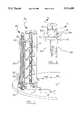
- FIG. 1is a partially cut-away perspective view of a paint colorant dispenser according to the invention
- FIG. 2is a perspective view of an adjustable stop assembly from the paint colorant dispenser of FIG. 1;
- FIG. 3is a section along the line 3--3 of FIG. 2;
- FIG. 4is a section along the line 4--4 of FIG. 3;
- FIG. 5is a section along the line 5--5 in FIG. 3;
- FIG. 6is a section through the pump assembly from the paint colorant dispenser of FIG. 1 with its piston in a lowered position;
- FIG. 7is a section through the pump assembly from the paint colorant dispenser of FIG. 1 with its piston in a raised position;
- FIG. 8is a detail of a stop mounting arm from the paint colorant dispenser of FIG. 1;
- FIG. 9is a section along the line 9--9 through the locking mechanism of the paint colorant dispenser shown in FIG. 6.
- a paint colorant dispenser 20incorporating the invention comprises a paint colorant reservoir 22 coupled to a measuring cylinder 26 through a valve 28.
- a piston 30is slidably and sealingly mounted inside measuring cylinder 26 at a lower end of a piston rod 32.
- Piston 30 and valve 28define a variable volume 29 (FIG. 7) inside measuring cylinder 26.
- piston rod 32The upper end of piston rod 32 is attached to a plunger handle 34. By grasping plunger handle 34 and moving it vertically a user can move piston 30 within cylinder 26 to vary variable volume 29.
- valve 28is turned so that reservoir 22 is in fluid communication with measuring cylinder 26 (FIG. 6). Then piston 30 is raised within measuring cylinder 26. As piston 30 is raised, paint colorant is drawn from reservoir 22, through valve 28 into volume 29 in measuring cylinder 26. The volume of paint colorant drawn into measuring cylinder 26 depends upon the diameter of measuring cylinder 26 and the stroke of piston 30.
- Valve 28is then turned so that measuring cylinder 26 is in fluid communication with a nozzle 33 (FIG. 7).
- piston 30is subsequently lowered the paint colorant filling the volume between piston 30 and the lower end of measuring cylinder 26 is expelled through nozzle 33.
- piston 30The travel of piston 30 is limited by stop assembly 38. A user can lift plunger handle 34 only until upper surface 39 of plunger handle 34 hits a stop 36 on a stop assembly 38.
- the stroke of piston 30, and, therefore, the quantity of paint colorant dispensed in a single stroke of piston 30,can be adjusted by moving stop 36 up or down.
- stop 36is mounted at the top end of a stop support member 40.
- stop support member 40Many configurations for stop support member 40 are possible. It is convenient to make stop support member 40 a rigid channel member having a longitudinal channel 41. Support member 40 is slidably affixed relative to cylinder 26. Support member 40 may be fixed at discrete positions relative to cylinder 26 by means of a coarse adjustment mechanism comprising spring loaded pins 44a, 44b which engage in holes 45 (or other pin-engaging indentations) on a rear face of support member 40.
- Holes 45are preferably arranged in two parallel rows 45a, 45b. Pin 44a aligns with row 45a, pin 44b aligns with row 45b. Holes 45 in row 45b are staggered relative to holes 45 in row 45a. This allows the position of stop 36 to be adjusted in increments L equal to one half of the spacing between adjacent holes 45 in either of rows 45a or 45b. As shown in FIG. 9, At each stop position, one of pins 44a or 44b is engaged in a hole 45.
- a lock bar 46is connected to pins 44a, 44b by a linkage 47.
- linkage 47slides pins 44a, 44b rearwardly, against the force of springs 48, and out of engagement with holes 45.
- Stop support member 40is then free to slide up or down relative to cylinder 26. Markings 49 may be provided on stop support member 40 so that an operator of dispenser 20 can quickly ascertain the state of the coarse adjustment.
- the spacing of holes 45 in rows 45a and 45bmay, for example, be such that the distance between two adjacent holes 45 is the same as the distance that piston 30 must move in cylinder 26 to displace one sixteenth of a fluid ounce. In this case, the movement of support arm 40 between two adjacent locking positions will be one half of this distance, corresponding to a displacement of one thirty-second of a fluid ounce by piston 30.
- stop 36is one end of a rod 50.
- Rod 50is threaded and passes through a mounting portion affixed to the upper end of stop support member 40.
- the mounting portioncomprises a threaded aperture 54.
- Rod 50projects through aperture 54 with stop 36 inside channel 41 on stop support member 40.
- the position of stop 36can therefore be adjusted by turning rod 50 with respect to aperture 54.
- the pitch of the threads on rod 50 and aperture 54are such that one full 360 degree rotation of rod 50 in aperture 54 causes rod 50 to move axially by at least the distance L which is the distance between adjacent locking positions of support member 40.
- Head 56 of rod 50is housed within a non-circular well 58 inside a knob 60 so that head 56 can slide axially inside knob 60 but cannot turn relative to knob 60.
- head 56 and well 58may both be square in section. When knob 60 is turned, rod 50 turns too and head 56 of rod 50 slides axially in well 58.
- Knob 60is retained by spring 62 which bears against the underside of head 56 and against a flange 65 which projects inwardly into well 58. Spring 62 forces knob 60 against a plate 69 which is affixed to support member 40.
- knob 60does not move axially with rod 50 with respect to plate 69 position indicating indicia such as marks 72 on knob 60 (FIG. 2) do not move toward or away from plate 69 as knob 60 turns. Consequently, the angle of rotation of rod 50 can be easily read by comparing the position of marks 72 to pin 75. As a less preferred alternative, the position of rod 50 can be read by comparing the position of a projection 70 or a mark on knob 60 to indicia (not shown) on plate 69.
- knob 60were free to rotate through more than one full revolution then some positions of knob 60 would correspond to two positions of stop 36. Consequently, pin 75 is provided on plate 69 and projection 70 is provided on knob 60 to prevent knob 60 from rotating by more than one full turn.
- the pitch of the threads on rod 50is such that stop 36 moves by the distance L when knob 60 is turned through the full range of motion permitted by pin 75 and projection 70.
- a detent ball 77which sits within a hole 78 in knob 60 is provided to facilitate repeatably setting knob 60 in selected intermediate positions corresponding to, for example, 1/4, 1/2, and 3/4 of the full rotary range of knob 60.
- the distance L in FIG. 6corresponds to a volume of 1/32 fluid ounce then an adjustment of knob 60 of 1/4 of its range would alter the amount of paint colorant dispensed by 1/128 fluid ounce. An adjustment of knob 60 over one half of its range would alter the amount of paint colorant dispensed by 1/64 fluid ounce.
- Indentations 79are provided on the top side of plate 69 for each selected position of knob 60.
- detent ball 77fits into one of indentations 79.
- detent ball 77snaps into place in one of indentations 79.
- Knob 60is then held in the selected position by detent ball 77.
- detent ball 77slightly lifts knob 60 and compresses spring 62.
- knob 60is in a position intermediate two selected positions then detent balls 77 slide smoothly on plate 69. As shown in FIG. 4, several detent balls 77 may be provided spaced apart on the underside of knob 60.
- detent balls 77 and indentations 79may be reversed so that detent balls 77 lie in recesses 78 on the top side of plate 69 and indentations 79 are on the underside of knob 60. Further, although it is not preferable to do so, detent balls 77 may be replaced with fixed projections which can interfit with indentations 79.
- measuring cylinder 26comprises a tube 80 which screws into a threaded socket 81 on the body 28a of valve 28.
- piston 30has a projecting cushion 85 shaped to conform closely to the shape of the lowermost end of volume 29.
- cushion 85projects past the end of tube 80 and fills up substantially all of the volume between piston 30 and valve 2.8. If any air does enter volume 29 then it is driven out by cushion 85 when piston 30 is fully lowered.
- Dispenser 20is calibrated with cushion 85 in place.
- Cushion 85may be formed integrally with piston 30. However, it is generally more cost effective to make cushion 85 from a suitable material such as nylon, and to attach cushion 85 to piston 30 with a screw 88 or any other suitable fastening means.
Landscapes
- Physics & Mathematics (AREA)
- Fluid Mechanics (AREA)
- General Physics & Mathematics (AREA)
- Coating Apparatus (AREA)
Abstract
Description
This invention relates to an apparatus for dispensing accurately metered quantities of paint colorant for tinting paint.
Paint of virtually any color can be custom made by beginning with a white base and adding precisely measured amounts of paint colorant of different colors. Sometimes to achieve a desired color it is necessary to dispense very small amounts of paint colorant.
It is important that a paint colorant dispenser have a quick, simple, easily repeatable operation. It is often necessary to prepare many small batches of paint of different colors. If the dispensing operation is not quick and simple then time is wasted and the likelihood of errors increases.
The color of paint can be greatly affected by small variations in the amount of colorant added. Consequently, a paint colorant dispenser must provide precise, repeatable settings.
Prior art paint colorant dispensers typically comprise a reservoir for storing paint colorant and a pump comprising a piston movable within a cylinder and a valve for placing the interior of the cylinder in fluid communication with either a paint colorant reservoir or an outlet. As the piston is raised, paint colorant is drawn into the cylinder through the valve. The valve is then switched to connect the cylinder to the outlet. As the piston is lowered, the paint colorant in the cylinder is expelled through the outlet. The amount of paint colorant dispensed is determined by the stroke of the piston and the bore of the cylinder.
Prior art paint colorant dispensers typically include a stop, adjustable in discrete increments, to limit the travel of the piston. An operator can dispense a selected amount of colorant by fixing the stop in a desired position, raising the piston to the stop, and then lowering the piston.
A difficulty with such paint colorant dispensers is that the stop can be fixed only in discrete positions. If the desired amount of paint colorant is between stop positions then the operator is forced to approximate the desired amount by lifting the piston to a position between stop positions. This method leads to unacceptable errors in the amount of colorant dispensed, especially if the piston is relatively large in diameter.
A previous paint colorant dispenser disclosed in U. S. Pat. No. 4,96.4,534 has two pistons, a small bore piston for dispensing small amounts of colorant, and a larger bore piston for dispensing larger amounts of colorant. Such twin pump dispensers have the disadvantage that the operator may need to manipulate two pistons to dispense a desired amount of colorant. This introduces extra steps into the dispensing process and increases the likelihood of errors. A further disadvantage is that such dispensers have many parts and seals which can lead to increased maintenance costs and reduced reliability.
Some prior art paint colorant dispensers approach the problem of accurately dispensing small amounts of paint colorant by requiring the user to replace a gauge rod in the stop assembly with a separate gauge rod. The separate gauge rod allows the stop to be fixed in a position in which only a small volume of colorant (for example 1/256 fluid ounces) is dispensed. A problem with this approach is that the dispenser should be separately calibrated for use with the separate gauge rod. This increases manufacturing costs. Furthermore, the separate gauge rod is easily lost and installing the separate gauge rod introduces extra steps to the dispensing process.
The invention provides a paint colorant dispenser which includes apparatus for adjusting the position of a stop for regulating the volume of paint colorant dispensed by the paint colorant dispenser. The paint colorant dispenser comprising a piston sealingly and slidably mounted in a cylinder having first and second ends and an axis and a stop contacting member on the piston. The apparatus comprises: a) a stop member comprising a central threaded portion, and a first end having a stop surface, the stop surface being axially aligned with the stop contacting member; b) a stop support member having a mounting portion at one end, the stop support member being slidably mounted with respect to the cylinder. The stop member passing through a threaded aperture in the mounting portion, with threads of the stop member engaged with threads of the aperture; c) coarse adjustment means associated with the stop support member for fixing the mounting portion in one of a plurality of positions equally spaced apart by a distance L along a line parallel to the axis of the cylinder; and d) a knob associated with the stop member for rotating the stop member in the aperture. The threads have a pitch such that in one rotation of the stop member, the stop surface moves by a distance of at least L along the line.
In a preferred embodiment the invention provides a paint colorant dispenser comprising: a cylinder comprising a tube and a valve body closing a lower end of the tube; a valve in the valve body, the valve having a first position wherein the cylinder is in fluid communication with a reservoir and a second position wherein the cylinder is in fluid communication with an outlet; a piston slidably and sealingly mounted within the cylinder; a piston rod connected to the piston, the piston rod comprising a stop contacting surface; a stop support member slidably mounted with respect to the cylinder; coarse stop adjustment means for temporarily fixing the stop support member in one of a plurality of positions equally spaced apart by a distance L; and fine adjustment means mounted to the stop support member. The fine adjustment means comprises: a stop mounting plate on the stop support member, the stop mounting plate comprising a threaded aperture axially aligned with stop contacting surface; a stop member comprising a central threaded portion engaged in the threaded aperture, and a lower stop surface; a knob on the stop member for turning the stop member in the aperture; and means for restricting rotation of the stop member and the knob to an angular range, the angular range being no more than one full rotation. The coarse stop adjustment means comprises: a plurality of indentations in the stop support member; a sliding pin selectively engageable in one of the indentations; a spring for urging the sliding pin into one of the indentations; and, a linkage associated with the sliding pin for selectively retracting the sliding pin. The threads on the stop member have a pitch such that in rotating the stop member through the angular range the stop surface moves by a distance of at least L along a line parallel to the axis.
In drawings which illustrate specific embodiments of the invention, but which should not be construed as restricting the spirit or scope of the invention in any way:
FIG. 1 is a partially cut-away perspective view of a paint colorant dispenser according to the invention;
FIG. 2 is a perspective view of an adjustable stop assembly from the paint colorant dispenser of FIG. 1;
FIG. 3 is a section along theline 3--3 of FIG. 2;
FIG. 4 is a section along theline 4--4 of FIG. 3;
FIG. 5 is a section along theline 5--5 in FIG. 3;
FIG. 6 is a section through the pump assembly from the paint colorant dispenser of FIG. 1 with its piston in a lowered position;
FIG. 7 is a section through the pump assembly from the paint colorant dispenser of FIG. 1 with its piston in a raised position;
FIG. 8 is a detail of a stop mounting arm from the paint colorant dispenser of FIG. 1; and,
FIG. 9 is a section along theline 9--9 through the locking mechanism of the paint colorant dispenser shown in FIG. 6.
As shown in FIG. 1, apaint colorant dispenser 20 incorporating the invention comprises apaint colorant reservoir 22 coupled to a measuringcylinder 26 through avalve 28. Apiston 30 is slidably and sealingly mounted inside measuringcylinder 26 at a lower end of apiston rod 32. Piston 30 andvalve 28 define a variable volume 29 (FIG. 7) inside measuringcylinder 26.
The upper end ofpiston rod 32 is attached to aplunger handle 34. By grasping plunger handle 34 and moving it vertically a user can movepiston 30 withincylinder 26 to varyvariable volume 29.
To operatepaint colorant dispenser 20valve 28 is turned so thatreservoir 22 is in fluid communication with measuring cylinder 26 (FIG. 6). Thenpiston 30 is raised within measuringcylinder 26. Aspiston 30 is raised, paint colorant is drawn fromreservoir 22, throughvalve 28 intovolume 29 in measuringcylinder 26. The volume of paint colorant drawn into measuringcylinder 26 depends upon the diameter of measuringcylinder 26 and the stroke ofpiston 30.
Valve 28 is then turned so that measuringcylinder 26 is in fluid communication with a nozzle 33 (FIG. 7). Whenpiston 30 is subsequently lowered the paint colorant filling the volume betweenpiston 30 and the lower end of measuringcylinder 26 is expelled throughnozzle 33.
The travel ofpiston 30 is limited bystop assembly 38. A user can liftplunger handle 34 only untilupper surface 39 of plunger handle 34 hits astop 36 on astop assembly 38. The stroke ofpiston 30, and, therefore, the quantity of paint colorant dispensed in a single stroke ofpiston 30, can be adjusted by movingstop 36 up or down.
As shown in FIGS. 1 and 6, stop 36 is mounted at the top end of astop support member 40. Many configurations forstop support member 40 are possible. It is convenient to make stop support member 40 a rigid channel member having alongitudinal channel 41.Support member 40 is slidably affixed relative tocylinder 26.Support member 40 may be fixed at discrete positions relative tocylinder 26 by means of a coarse adjustment mechanism comprising spring loadedpins support member 40.
Alock bar 46 is connected topins linkage 47. Whenlock bar 46 is pushed inwardly,linkage 47slides pins springs 48, and out of engagement withholes 45. Stopsupport member 40 is then free to slide up or down relative tocylinder 26.Markings 49 may be provided onstop support member 40 so that an operator ofdispenser 20 can quickly ascertain the state of the coarse adjustment.
The spacing ofholes 45 inrows adjacent holes 45 is the same as the distance thatpiston 30 must move incylinder 26 to displace one sixteenth of a fluid ounce. In this case, the movement ofsupport arm 40 between two adjacent locking positions will be one half of this distance, corresponding to a displacement of one thirty-second of a fluid ounce bypiston 30.
It is not practical to makeholes 45 too close together. Ifholes 45 andpins dispenser 20 rugged. Therefore, for a given diameter ofpiston 30, there is a practical lower limit to the size of the increments in which the volume of paint colorant dispensed bydispenser 20 can be adjusted with the coarse adjustment mechanism described above.
Other equivalent coarse adjustment mechanisms which involve a member pivoting or sliding into engagement with spaced holes or indentations in a stop support member have similar limitations.
Accordingly, the invention provides for fine adjustment of the position ofstop 36 by means ofstop assembly 38. As shown in FIG. 3, stop 36 is one end of arod 50.Rod 50 is threaded and passes through a mounting portion affixed to the upper end ofstop support member 40. The mounting portion comprises a threadedaperture 54.Rod 50 projects throughaperture 54 withstop 36 insidechannel 41 onstop support member 40. The position ofstop 36 can therefore be adjusted by turningrod 50 with respect toaperture 54. The pitch of the threads onrod 50 andaperture 54 are such that one full 360 degree rotation ofrod 50 inaperture 54causes rod 50 to move axially by at least the distance L which is the distance between adjacent locking positions ofsupport member 40.
Becauseknob 60 does not move axially withrod 50 with respect to plate 69 position indicating indicia such asmarks 72 on knob 60 (FIG. 2) do not move toward or away fromplate 69 asknob 60 turns. Consequently, the angle of rotation ofrod 50 can be easily read by comparing the position ofmarks 72 to pin 75. As a less preferred alternative, the position ofrod 50 can be read by comparing the position of aprojection 70 or a mark onknob 60 to indicia (not shown) onplate 69.
Ifknob 60 were free to rotate through more than one full revolution then some positions ofknob 60 would correspond to two positions ofstop 36. Consequently,pin 75 is provided onplate 69 andprojection 70 is provided onknob 60 to preventknob 60 from rotating by more than one full turn. Preferably, the pitch of the threads onrod 50 is such thatstop 36 moves by the distance L whenknob 60 is turned through the full range of motion permitted bypin 75 andprojection 70.
As shown in FIGS. 3, 4 and 5, adetent ball 77 which sits within ahole 78 inknob 60 is provided to facilitate repeatably settingknob 60 in selected intermediate positions corresponding to, for example, 1/4, 1/2, and 3/4 of the full rotary range ofknob 60. For example, if the distance L in FIG. 6 corresponds to a volume of 1/32 fluid ounce then an adjustment ofknob 60 of 1/4 of its range would alter the amount of paint colorant dispensed by 1/128 fluid ounce. An adjustment ofknob 60 over one half of its range would alter the amount of paint colorant dispensed by 1/64 fluid ounce.
The positions ofdetent balls 77 andindentations 79 may be reversed so thatdetent balls 77 lie inrecesses 78 on the top side ofplate 69 andindentations 79 are on the underside ofknob 60. Further, although it is not preferable to do so,detent balls 77 may be replaced with fixed projections which can interfit withindentations 79.
Typically, as shown in FIGS. 6 and 7, measuringcylinder 26 comprises atube 80 which screws into a threadedsocket 81 on thebody 28a ofvalve 28. With this construction, ifpiston 30 has a flat lower face andpiston 30 is fully lowered,piston 30 does not reducevolume 29 to zero. This can be a problem because the accuracy ofdispenser 20 may be impaired if air entersvolume 29. Ifvolume 29 is not reduced nearly to zero whenpiston 30 is fully lowered then air which entersvolume 29 will not be automatically expelled fromvolume 29. This problem could affect the accuracy of adispenser 20 in which small changes made in the travel of a relativelylarge diameter piston 30 as a result of changes in the position ofstop 36 should result in accurately corresponding changes in the amount of paint colorant dispensed.
Preferably,piston 30 has a projectingcushion 85 shaped to conform closely to the shape of the lowermost end ofvolume 29. Whenpiston 30 is fully lowered, cushion 85 projects past the end oftube 80 and fills up substantially all of the volume betweenpiston 30 and valve 2.8. If any air does entervolume 29 then it is driven out bycushion 85 whenpiston 30 is fully lowered.Dispenser 20 is calibrated withcushion 85 in place.
As will be apparent to those skilled in the art in the light of the foregoing disclosure, many alterations and modifications are possible in the practice of this invention without departing from the spirit or scope thereof. Accordingly, the scope of the invention is to be construed in accordance with the substance defined by the following claims.
Claims (20)
1. A paint colorant dispenser comprising: a piston sealingly and slidably mounted in a cylinder having first and second ends and an axis; a stop contacting member on said piston, and apparatus for adjusting the position of a stop for regulating the volume of paint colorant dispensed by the paint colorant dispenser, said apparatus comprising:
a) a stop member comprising a central threaded portion, and a first end having a stop surface, said stop surface axially aligned with said stop contacting member;
b) a stop support member slidably mounted with respect to said cylinder, said stop support member having a mounting portion at one end thereof, said stop member passing through a threaded aperture in said mounting portion, with said threaded portion of said stop member engaged with said threads of said aperture;
c) coarse adjustment means associated with said stop support member for fixing said stop support member in one of a plurality of positions equally spaced apart by a distance L along a line parallel to said axis of said cylinder;
d) a knob associated with said stop member for rotating said stop member in said aperture;
wherein said threads have a pitch such that in one rotation of said stop member, said stop surface moves by a distance of at least L along said line.
2. The paint colorant dispenser of claim 1 wherein said stop member comprises a head having a non-circular section and said head is disposed for sliding without rotation relative to said knob within a non-circular well in said knob.
3. The paint colorant dispenser of claim 2 wherein said head is square in section and said well is square in section.
4. The paint colorant dispenser of claim 2 wherein said knob comprises a flange projecting inwardly into said well and further comprising a compression spring disposed between said flange and a surface of said head for biasing a surface of said knob against a surface of said mounting portion.
5. The paint colorant dispenser of claim 4 further comprising travel limiting means associated with said knob for limiting the range of rotary motion of said knob to no more than one full rotation of said knob.
6. The paint colorant dispenser of claim 5 wherein said travel limiting means comprise a projection from said surface of said mounting portion adjacent said knob and a projection extending radially from said knob.
7. The paint colorant dispenser of claim 6 further comprising indicia on said surface of said mounting portion adjacent said knob at selected positions around said knob for indicating an angle of rotation of said knob.
8. The paint colorant dispenser of claim 7 further comprising detent means for holding said knob in a selected rotary position with respect to said mounting portion.
9. The paint colorant dispenser of claim 8 wherein said detent means comprises a projection from said surface of said mounting portion and an indentation in said surface of said knob.
10. The paint colorant dispenser of claim 9 wherein said projection comprises a ball disposed in a hole in said surface of said mounting portion.
11. The paint colorant dispenser of claim 8 wherein said detent means comprises a projection from said surface of said knob and an indentation in said surface of said mounting portion.
12. The paint colorant dispenser of claim 11 wherein said projection comprises a ball disposed in a hole in said surface of said knob.
13. The paint colorant dispenser of claim 1 wherein said coarse adjustment means comprises a plurality of spaced apart indentations in said support arm and a locking member movable between a first position wherein said locking member is engaged in one of said indentations and a second position wherein said locking member is not engaged in any of said indentations.
14. The paint colorant dispenser of claim 13 wherein said indentations are holes and said locking member comprises a pin, said pin slidably mounted with respect to said cylinder.
15. A paint colorant dispenser comprising:
a. a cylinder comprising a tube and a valve body closing a lower end of said tube;
b. a valve in said valve body, said valve having a first position wherein said cylinder is in fluid communication with a reservoir and a second position wherein said cylinder is in fluid communication with an outlet;
c. a piston slidably and sealingly mounted within said cylinder;
d. a piston rod connected to said piston, said piston rod comprising a stop contacting surface;
e. a stop support member slidably mounted with respect to said cylinder,
f. coarse stop adjustment means for temporarily fixing said stop support member in one of a plurality of positions equally spaced apart by a distance L, said coarse stop adjustment means comprising:
i. a plurality of indentations in said stop support member;
ii. a sliding pin selectively engageable in one of said indentations;
iii. a spring for urging said sliding pin into said one of said indentations; and,
iv. a linkage associated with said sliding pin for selectively retracting said sliding pin;
g. fine adjustment means mounted to said stop support member, said fine adjustment means comprising:
i. a stop mounting plate on said stop support member, said stop mounting plate comprising a threaded aperture axially aligned with said stop contacting surface;
ii. a stop member comprising a central threaded portion engaged in said threaded aperture, and a lower stop surface;
iii. a knob on said stop member for turning said stop member in said aperture;
iv. means for restricting rotation of said stop member and said knob to an angular range, said angular range being no more than one full rotation;
wherein said threads on said stop member have a pitch such that in rotating said stop member through said angular range, said stop surface moves by a distance of at least L along a line parallel to said axis.
16. The paint colorant dispenser of claim 15 wherein there is space between said lower end of said tube and said valve and, when said piston is at a lowermost position within said cylinder, a portion of said piston projects past said lower end of said tube and occupies substantially all of said space.
17. The paint colorant dispenser of claim 16 wherein said projecting portion of said piston is a plastic cushion affixed to said piston.
18. The paint colorant dispenser of claim 15 wherein said stop member comprises a head having a non-circular section and said head is disposed for sliding without rotation relative to said knob within a non-circular well in said knob.
19. The paint colorant dispenser of claim 18 wherein said knob comprises a flange projecting inwardly into said well and further comprising a compression spring disposed between said flange and a surface of said head for biasing a surface of said knob against a surface of said mounting portion.
20. The paint colorant dispenser of claim 19 wherein said stop support member comprises a longitudinal channel and said stop member projects through said aperture into said channel.
Priority Applications (1)
| Application Number | Priority Date | Filing Date | Title |
|---|---|---|---|
| US08/259,330US5511695A (en) | 1994-06-13 | 1994-06-13 | Paint colorant dispenser |
Applications Claiming Priority (1)
| Application Number | Priority Date | Filing Date | Title |
|---|---|---|---|
| US08/259,330US5511695A (en) | 1994-06-13 | 1994-06-13 | Paint colorant dispenser |
Publications (1)
| Publication Number | Publication Date |
|---|---|
| US5511695Atrue US5511695A (en) | 1996-04-30 |
Family
ID=22984497
Family Applications (1)
| Application Number | Title | Priority Date | Filing Date |
|---|---|---|---|
| US08/259,330Expired - LifetimeUS5511695A (en) | 1994-06-13 | 1994-06-13 | Paint colorant dispenser |
Country Status (1)
| Country | Link |
|---|---|
| US (1) | US5511695A (en) |
Cited By (21)
| Publication number | Priority date | Publication date | Assignee | Title |
|---|---|---|---|---|
| US5944893A (en)* | 1997-06-19 | 1999-08-31 | Anderson; Dean Robert Gary | Metering device for paint for digital printing |
| US5972111A (en)* | 1997-06-19 | 1999-10-26 | Anderson; Dean Robert Gary | Metering device for paint for digital printing |
| WO2000046506A1 (en) | 1999-02-02 | 2000-08-10 | Corob International Ag | Injection pump for dye dispensing machine |
| US6190454B1 (en) | 1997-06-19 | 2001-02-20 | Dean Robert Gary Anderson | Printer cartridge |
| WO2001055681A1 (en)* | 2000-01-28 | 2001-08-02 | Novartis Ag | Dispensing device |
| US6786971B2 (en) | 1997-06-19 | 2004-09-07 | Dean Robert Gary Anderson | Method and apparatus for digital printing |
| US20050194403A1 (en)* | 2004-02-27 | 2005-09-08 | Mink Johannes H. | Fluid and hair-dye dispensers |
| US20070289991A1 (en)* | 2006-06-20 | 2007-12-20 | Larry Jensen | Colorant Dispenser Having an Outlet Control Valve |
| EP2116394A1 (en)* | 2008-05-06 | 2009-11-11 | Cps Color Equipment Oy | Arrangement for dispensing colour paste, apparatus and method |
| US20100318220A1 (en)* | 2008-03-03 | 2010-12-16 | The Saranow Group, Llc | Blending station apparatus and method for using the same |
| US20110100504A1 (en)* | 2008-03-03 | 2011-05-05 | The Saranow Group, Llc | Blending station apparatus and method for using the same |
| US8336582B2 (en) | 2008-03-03 | 2012-12-25 | Saranow Mitchell H | Method and system for the preparation of hair dye colors |
| US8393358B2 (en) | 2008-03-03 | 2013-03-12 | SureTint Technologies, LLC | Method for manual dispensing using standardized packaging |
| US8897915B2 (en) | 2008-03-03 | 2014-11-25 | SureTint Technologies, LLC | Inventory security management for a hair dye storage system |
| US9177339B2 (en) | 2008-03-03 | 2015-11-03 | Sure Tint Technologies, LLC | System and method for color preparation and management |
| WO2016059551A2 (en) | 2014-10-13 | 2016-04-21 | Alfa S.R.L. | Positive-displacement pump and pumping group for fluid products and method for the use thereof |
| US9414665B2 (en) | 2008-03-03 | 2016-08-16 | SureTint Technologies, LLC | Blending color and control management system |
| US9877569B2 (en) | 2011-02-24 | 2018-01-30 | SureTint Technologies, LLC | System and method for batch sizing hair dye mixtures |
| US10897979B1 (en) | 2019-09-12 | 2021-01-26 | SureTint Technologies, LLC | System and method for hair dye color conversion |
| US11235298B2 (en) | 2008-03-03 | 2022-02-01 | SureTint Technologies, LLC | Blending station apparatus and method for using the same |
| US11246395B2 (en) | 2008-03-03 | 2022-02-15 | SureTint Technologies, LLC | Color conversion system and method |
Citations (13)
| Publication number | Priority date | Publication date | Assignee | Title |
|---|---|---|---|---|
| US3275042A (en)* | 1964-09-17 | 1966-09-27 | Strazdins Atis | Liquid dispensing apparatus |
| US3601845A (en)* | 1969-07-25 | 1971-08-31 | Arthur Mavrich | Sausage casing stuffing apparatus |
| US3802608A (en)* | 1972-04-10 | 1974-04-09 | Packard Instrument Co Inc | Liquid metering device with concentric pistons and unidirectional liquid flow |
| US3805998A (en)* | 1972-11-17 | 1974-04-23 | M Croslin | Dispensing pipette |
| US4027785A (en)* | 1976-04-12 | 1977-06-07 | Chicago Commutator, Inc. | Dual pump colorant dispenser |
| DE2702539A1 (en)* | 1976-02-12 | 1977-08-18 | William John Roach | DEVICE FOR DISPENSING LIQUID IN EXACTLY PRE-DETERMINED QUANTITIES |
| US4273257A (en)* | 1977-07-18 | 1981-06-16 | Sherwood Medical Industries Inc. | Jar mounted pipettor |
| US4293010A (en)* | 1979-10-25 | 1981-10-06 | A-T-O Inc. | Adjustable volumetric filler head |
| US4456152A (en)* | 1982-05-03 | 1984-06-26 | Young Don H | Measuring and dispensing apparatus |
| US4526294A (en)* | 1982-02-22 | 1985-07-02 | Glasgeratebau Hirschmann | Dispenser for dispensing liquids in controlled quantities from a bottle |
| US4781312A (en)* | 1986-07-03 | 1988-11-01 | Strazdins (International) Pty. Limited | Liquid dispenser |
| US4801051A (en)* | 1984-03-26 | 1989-01-31 | Nordson Corporation | Flow control device for a fluid dispensing apparatus |
| US4964534A (en)* | 1987-06-24 | 1990-10-23 | Strazdins (International) Pty. Limited | Double piston colorant dispenser |
- 1994
- 1994-06-13USUS08/259,330patent/US5511695A/ennot_activeExpired - Lifetime
Patent Citations (14)
| Publication number | Priority date | Publication date | Assignee | Title |
|---|---|---|---|---|
| US3275042A (en)* | 1964-09-17 | 1966-09-27 | Strazdins Atis | Liquid dispensing apparatus |
| US3601845A (en)* | 1969-07-25 | 1971-08-31 | Arthur Mavrich | Sausage casing stuffing apparatus |
| US3802608A (en)* | 1972-04-10 | 1974-04-09 | Packard Instrument Co Inc | Liquid metering device with concentric pistons and unidirectional liquid flow |
| US3805998A (en)* | 1972-11-17 | 1974-04-23 | M Croslin | Dispensing pipette |
| DE2702539A1 (en)* | 1976-02-12 | 1977-08-18 | William John Roach | DEVICE FOR DISPENSING LIQUID IN EXACTLY PRE-DETERMINED QUANTITIES |
| US4027785A (en)* | 1976-04-12 | 1977-06-07 | Chicago Commutator, Inc. | Dual pump colorant dispenser |
| US4273257A (en)* | 1977-07-18 | 1981-06-16 | Sherwood Medical Industries Inc. | Jar mounted pipettor |
| US4293010A (en)* | 1979-10-25 | 1981-10-06 | A-T-O Inc. | Adjustable volumetric filler head |
| US4526294A (en)* | 1982-02-22 | 1985-07-02 | Glasgeratebau Hirschmann | Dispenser for dispensing liquids in controlled quantities from a bottle |
| US4456152A (en)* | 1982-05-03 | 1984-06-26 | Young Don H | Measuring and dispensing apparatus |
| US4801051A (en)* | 1984-03-26 | 1989-01-31 | Nordson Corporation | Flow control device for a fluid dispensing apparatus |
| US4781312A (en)* | 1986-07-03 | 1988-11-01 | Strazdins (International) Pty. Limited | Liquid dispenser |
| US4964534A (en)* | 1987-06-24 | 1990-10-23 | Strazdins (International) Pty. Limited | Double piston colorant dispenser |
| US4966308A (en)* | 1987-06-24 | 1990-10-30 | Strazdins (International) Pty. Limited | Double piston colorant dispenser |
Cited By (59)
| Publication number | Priority date | Publication date | Assignee | Title |
|---|---|---|---|---|
| US6786971B2 (en) | 1997-06-19 | 2004-09-07 | Dean Robert Gary Anderson | Method and apparatus for digital printing |
| US5944893A (en)* | 1997-06-19 | 1999-08-31 | Anderson; Dean Robert Gary | Metering device for paint for digital printing |
| US6090445A (en)* | 1997-06-19 | 2000-07-18 | Anderson; Dean Robert Gary | Method of digital printing |
| US6089160A (en)* | 1997-06-19 | 2000-07-18 | Anderson; Dean Robert Gary | Metering device for paint for digital printing |
| US6190454B1 (en) | 1997-06-19 | 2001-02-20 | Dean Robert Gary Anderson | Printer cartridge |
| US6319555B1 (en) | 1997-06-19 | 2001-11-20 | Dean Robert Gary Anderson | Metering device for paint for digital printing |
| US6398869B1 (en) | 1997-06-19 | 2002-06-04 | Dean Robert Gary Anderson | Metering device for paint for digital printing |
| US5972111A (en)* | 1997-06-19 | 1999-10-26 | Anderson; Dean Robert Gary | Metering device for paint for digital printing |
| WO2000046506A1 (en) | 1999-02-02 | 2000-08-10 | Corob International Ag | Injection pump for dye dispensing machine |
| WO2001055681A1 (en)* | 2000-01-28 | 2001-08-02 | Novartis Ag | Dispensing device |
| US6770056B2 (en) | 2000-01-28 | 2004-08-03 | Novartis Ag | Dispensing device |
| US20050194403A1 (en)* | 2004-02-27 | 2005-09-08 | Mink Johannes H. | Fluid and hair-dye dispensers |
| US20060191956A1 (en)* | 2004-02-27 | 2006-08-31 | Lenteq, Lp | Fluid and hair-dye dispensers |
| US7121430B2 (en) | 2004-02-27 | 2006-10-17 | Lentep, Lp | Fluid and hair-dye dispensers |
| US20060231578A1 (en)* | 2004-02-27 | 2006-10-19 | Lenteq, Lp | Fluid and hair-dye dispensers |
| US20060261090A1 (en)* | 2004-02-27 | 2006-11-23 | Lenteq, Lp | Fluid and hair dye dispensers having central support column |
| US20060261089A1 (en)* | 2004-02-27 | 2006-11-23 | Lenteq, Lp | Hair dye dispenser |
| US20060278663A1 (en)* | 2004-02-27 | 2006-12-14 | Lenteq, Lp | Valve actuator for a fluid dispenser |
| US20060283889A1 (en)* | 2004-02-27 | 2006-12-21 | Lenteq, Lp | Two disc valve pump assembly for a fluid dispenser |
| US7185789B2 (en) | 2004-02-27 | 2007-03-06 | Lenteq, Lp | Hair dye dispenser |
| US7597217B2 (en) | 2004-02-27 | 2009-10-06 | Lenteq, Lp | Two disc valve pump assembly for a fluid dispenser |
| US20070289991A1 (en)* | 2006-06-20 | 2007-12-20 | Larry Jensen | Colorant Dispenser Having an Outlet Control Valve |
| US8393363B2 (en) | 2008-03-03 | 2013-03-12 | SureTint Technologies, LLC | Blending station apparatus and method for using the same |
| US9919278B2 (en) | 2008-03-03 | 2018-03-20 | SureTint Technologies, LLC | Blending station apparatus and method for using the same |
| US12245680B2 (en) | 2008-03-03 | 2025-03-11 | B&R Holdings Llc | Color conversion system and method |
| US20100318220A1 (en)* | 2008-03-03 | 2010-12-16 | The Saranow Group, Llc | Blending station apparatus and method for using the same |
| US20110100504A1 (en)* | 2008-03-03 | 2011-05-05 | The Saranow Group, Llc | Blending station apparatus and method for using the same |
| US11950683B2 (en) | 2008-03-03 | 2024-04-09 | B&R Holdings, Llc | Color conversion system and method |
| US8336582B2 (en) | 2008-03-03 | 2012-12-25 | Saranow Mitchell H | Method and system for the preparation of hair dye colors |
| US11918964B2 (en) | 2008-03-03 | 2024-03-05 | SureTint Technologies, LLC | Blending station apparatus and method for using the same |
| US8393358B2 (en) | 2008-03-03 | 2013-03-12 | SureTint Technologies, LLC | Method for manual dispensing using standardized packaging |
| US11246395B2 (en) | 2008-03-03 | 2022-02-15 | SureTint Technologies, LLC | Color conversion system and method |
| US8567455B2 (en) | 2008-03-03 | 2013-10-29 | SureTint Technologies, LLC | Blending station apparatus and method for using the same |
| US8897915B2 (en) | 2008-03-03 | 2014-11-25 | SureTint Technologies, LLC | Inventory security management for a hair dye storage system |
| US9177339B2 (en) | 2008-03-03 | 2015-11-03 | Sure Tint Technologies, LLC | System and method for color preparation and management |
| US11235298B2 (en) | 2008-03-03 | 2022-02-01 | SureTint Technologies, LLC | Blending station apparatus and method for using the same |
| US9414665B2 (en) | 2008-03-03 | 2016-08-16 | SureTint Technologies, LLC | Blending color and control management system |
| US9524605B2 (en) | 2008-03-03 | 2016-12-20 | SureTint Technologies, LLC | System and method for color preparation and management |
| US9623388B2 (en) | 2008-03-03 | 2017-04-18 | SureTint Technologies, LLC | Blending station apparatus and method for using the same |
| US9839278B2 (en) | 2008-03-03 | 2017-12-12 | SureTint Technologies, LLC | Blending color and control management system |
| US11103841B2 (en) | 2008-03-03 | 2021-08-31 | SureTint Technologies, LLC | Blending station apparatus and method for using the same |
| US11052359B2 (en) | 2008-03-03 | 2021-07-06 | SureTint Technologies, LLC | Blending station apparatus and method for using the same |
| US10182638B2 (en) | 2008-03-03 | 2019-01-22 | SureTint Technologies, LLC | Blending color and control management system |
| US10893740B2 (en) | 2008-03-03 | 2021-01-19 | SureTint Technologies, LLC | Color conversion system and method |
| US20090277925A1 (en)* | 2008-05-06 | 2009-11-12 | Cps Color Equipment Oy | Arrangement for dispensing colour paste, apparatus and method |
| US8191733B2 (en) | 2008-05-06 | 2012-06-05 | Cps Color Equipment Oy | Arrangement for dispensing colour paste, apparatus and method |
| CN101576069A (en)* | 2008-05-06 | 2009-11-11 | Cps颜料设备公司 | Arrangement for dispensing color paste, apparatus and method |
| EP2116394A1 (en)* | 2008-05-06 | 2009-11-11 | Cps Color Equipment Oy | Arrangement for dispensing colour paste, apparatus and method |
| CN101576069B (en)* | 2008-05-06 | 2013-09-25 | Cps颜料设备公司 | Arrangement for dispensing color paste, apparatus and method |
| US11375801B2 (en) | 2011-02-24 | 2022-07-05 | SureTint Technologies, LLC | System and method for batch sizing hair dye mixtures |
| US10716386B2 (en) | 2011-02-24 | 2020-07-21 | SureTint Technologies, LLC | System and method for batch sizing hair dye mixtures |
| US9877569B2 (en) | 2011-02-24 | 2018-01-30 | SureTint Technologies, LLC | System and method for batch sizing hair dye mixtures |
| US11053930B2 (en) | 2014-10-13 | 2021-07-06 | Alfa S. R. L. | Positive-displacement pump and pumping group for fluid products and method for the use thereof |
| WO2016059551A2 (en) | 2014-10-13 | 2016-04-21 | Alfa S.R.L. | Positive-displacement pump and pumping group for fluid products and method for the use thereof |
| EP3483434A1 (en) | 2014-10-13 | 2019-05-15 | Alfa S.r.l. | Positive-displacement pump and pumping group for fluid products and method for the use thereof |
| US11344103B2 (en) | 2019-09-12 | 2022-05-31 | SureTint Technologies, LLC | System and method for hair dye color conversion |
| US11925251B2 (en) | 2019-09-12 | 2024-03-12 | SureTint Technologies, LLC | System and method for hair dye color conversion |
| US10897979B1 (en) | 2019-09-12 | 2021-01-26 | SureTint Technologies, LLC | System and method for hair dye color conversion |
| US12408744B2 (en) | 2019-09-12 | 2025-09-09 | B&R Holdings, Llc | System and method for hair dye color conversion |
Similar Documents
| Publication | Publication Date | Title |
|---|---|---|
| US5511695A (en) | Paint colorant dispenser | |
| CA1081184A (en) | Jar mounted pipettor | |
| US4027785A (en) | Dual pump colorant dispenser | |
| DE4335863C1 (en) | Piston-operated pipette | |
| US4074831A (en) | Liquid metering device with adjustable stops | |
| US4072247A (en) | Liquid dispensing device | |
| US4526294A (en) | Dispenser for dispensing liquids in controlled quantities from a bottle | |
| US4456152A (en) | Measuring and dispensing apparatus | |
| EP1743701B1 (en) | Piston pipette | |
| US4415101A (en) | Incremental liquid dispensing device | |
| US4330070A (en) | Relating to dose determining means of paste dispenser | |
| EP1460001A1 (en) | Pump with function of measuring fixed amount | |
| US6164499A (en) | Paint colorant dispenser and valve therefor | |
| US4781312A (en) | Liquid dispenser | |
| WO1994021554A1 (en) | Improved dispensing apparatus | |
| SU1088650A3 (en) | Multiple-batch pipet | |
| US4964534A (en) | Double piston colorant dispenser | |
| US5983728A (en) | Watch-type pressure gauge | |
| JPS6234587Y2 (en) | ||
| US6164497A (en) | Paint colorant dispenser with notched gauge rod | |
| GB2114677A (en) | Liquid dispensing devices | |
| US3770169A (en) | Motorized liquid dispenser with an accurate dispensing volume adjustment | |
| US7607554B2 (en) | Peristaltic precision metering device, system and method of use thereof | |
| US4077750A (en) | Adjustable liquid dispensing pump | |
| US4178803A (en) | Pipetting devices |
Legal Events
| Date | Code | Title | Description |
|---|---|---|---|
| AS | Assignment | Owner name:HERO INDUSTRIES, INC., CANADA Free format text:ASSIGNMENT OF ASSIGNORS INTEREST;ASSIGNORS:CHIA, JULIAN YEW-POH;JENNE, GARY BERNHARD;REEL/FRAME:007044/0252 Effective date:19940601 | |
| STCF | Information on status: patent grant | Free format text:PATENTED CASE | |
| FEPP | Fee payment procedure | Free format text:PAYOR NUMBER ASSIGNED (ORIGINAL EVENT CODE: ASPN); ENTITY STATUS OF PATENT OWNER: SMALL ENTITY | |
| FPAY | Fee payment | Year of fee payment:4 | |
| FPAY | Fee payment | Year of fee payment:8 | |
| AS | Assignment | Owner name:I.C.T.C. HOLDINGS CORPORATION, CANADA Free format text:ASSIGNMENT OF ASSIGNORS INTEREST;ASSIGNOR:H.E.R.O. INDUSTRIES A DIVISION OF MIDDLEFIELD BANCORP LIMITED;REEL/FRAME:015509/0483 Effective date:20041029 | |
| FPAY | Fee payment | Year of fee payment:12 |