US5511367A - Lawn mower having additinal improved trim featuure - Google Patents
Lawn mower having additinal improved trim featuureDownload PDFInfo
- Publication number
- US5511367A US5511367AUS08/283,710US28371094AUS5511367AUS 5511367 AUS5511367 AUS 5511367AUS 28371094 AUS28371094 AUS 28371094AUS 5511367 AUS5511367 AUS 5511367A
- Authority
- US
- United States
- Prior art keywords
- relative
- lawn mower
- drive wheels
- speed
- operator
- Prior art date
- Legal status (The legal status is an assumption and is not a legal conclusion. Google has not performed a legal analysis and makes no representation as to the accuracy of the status listed.)
- Expired - Lifetime
Links
- 230000007935neutral effectEffects0.000claimsabstractdescription34
- 241000321728Tritogonia verrucosaSpecies0.000claimsdescription4
- 238000002485combustion reactionMethods0.000claimsdescription4
- 239000012530fluidSubstances0.000description7
- 230000006835compressionEffects0.000description3
- 238000007906compressionMethods0.000description3
- 238000010276constructionMethods0.000description3
- 210000005069earsAnatomy0.000description3
- 230000009471actionEffects0.000description2
- 210000000988bone and boneAnatomy0.000description2
- 230000000994depressogenic effectEffects0.000description2
- 210000004247handAnatomy0.000description2
- 210000003813thumbAnatomy0.000description2
- 244000025254Cannabis sativaSpecies0.000description1
- 210000003811fingerAnatomy0.000description1
- 230000003993interactionEffects0.000description1
- 230000007246mechanismEffects0.000description1
- 230000004048modificationEffects0.000description1
- 238000012986modificationMethods0.000description1
Images


Classifications
- A—HUMAN NECESSITIES
- A01—AGRICULTURE; FORESTRY; ANIMAL HUSBANDRY; HUNTING; TRAPPING; FISHING
- A01D—HARVESTING; MOWING
- A01D34/00—Mowers; Mowing apparatus of harvesters
- A01D34/01—Mowers; Mowing apparatus of harvesters characterised by features relating to the type of cutting apparatus
- A01D34/412—Mowers; Mowing apparatus of harvesters characterised by features relating to the type of cutting apparatus having rotating cutters
- A01D34/63—Mowers; Mowing apparatus of harvesters characterised by features relating to the type of cutting apparatus having rotating cutters having cutters rotating about a vertical axis
- A01D34/67—Mowers; Mowing apparatus of harvesters characterised by features relating to the type of cutting apparatus having rotating cutters having cutters rotating about a vertical axis hand-guided by a walking operator
- A01D34/68—Mowers; Mowing apparatus of harvesters characterised by features relating to the type of cutting apparatus having rotating cutters having cutters rotating about a vertical axis hand-guided by a walking operator with motor driven cutters or wheels
- A01D34/6806—Driving mechanisms
- A—HUMAN NECESSITIES
- A01—AGRICULTURE; FORESTRY; ANIMAL HUSBANDRY; HUNTING; TRAPPING; FISHING
- A01D—HARVESTING; MOWING
- A01D34/00—Mowers; Mowing apparatus of harvesters
- A01D34/01—Mowers; Mowing apparatus of harvesters characterised by features relating to the type of cutting apparatus
- A01D34/412—Mowers; Mowing apparatus of harvesters characterised by features relating to the type of cutting apparatus having rotating cutters
- A01D34/63—Mowers; Mowing apparatus of harvesters characterised by features relating to the type of cutting apparatus having rotating cutters having cutters rotating about a vertical axis
- A01D34/67—Mowers; Mowing apparatus of harvesters characterised by features relating to the type of cutting apparatus having rotating cutters having cutters rotating about a vertical axis hand-guided by a walking operator
- A01D34/68—Mowers; Mowing apparatus of harvesters characterised by features relating to the type of cutting apparatus having rotating cutters having cutters rotating about a vertical axis hand-guided by a walking operator with motor driven cutters or wheels
- A01D2034/6843—Control levers on the handle of the mower
- A—HUMAN NECESSITIES
- A01—AGRICULTURE; FORESTRY; ANIMAL HUSBANDRY; HUNTING; TRAPPING; FISHING
- A01D—HARVESTING; MOWING
- A01D2101/00—Lawn-mowers
Definitions
- This inventionrelates in general to lawn mowers, and particularly relates to controls for a lawn mower providing improved steering features.
- an enginepowers one or more hydraulic pumps, which drive two hydraulic motors which themselves drive wheels of a lawn mower.
- hydraulic pumpspowers one or more hydraulic pumps, which drive two hydraulic motors which themselves drive wheels of a lawn mower.
- the relative speed and rotation of the drive wheelsmay likewise be controlled.
- a single enginedrives two fluid pumps which drive two corresponding motors, each being coupled to a corresponding rear drive wheel. Control arms control the flow from the pumps.
- trim featureBy providing a trim feature, the operator can fine-tune the speed of the wheels to cause the mower to run in a substantially straight line.
- a trim featuremay also be helpful when an operator is cutting on a hill; in such situations the mower may tend to turn downhill, and the trim feature can be used to compensate for such movement.
- a trim feature requiring no tools for adjustmentwould also be advantageous.
- the present inventionovercomes disadvantages in the prior art by providing a lawn mower having steering controls which allow the steering of the lawn mower to be "trimmed", as well as a lawn mower having an improved locking feature.
- FIG. 1is a front, right side pictorial view of a lawn mower according to the present invention.
- FIG. 2is a front, right side pictorial partial view of the upper handle portion of the lawn mower of FIG. 1.
- FIG. 3is an exploded view of the trim subassembly and tie rod according to the present invention.
- FIG. 4is a view similar to that of FIG. 2, illustrating operation of the joystick, with the joystick in its maximum forward speed position, and with the trim leftward
- FIG. 5is an exploded view of a part of the handle assembly according to the present invention.
- FIG. 6is an exploded view illustrating the interaction of the hydraulic pumps and the lower locking bar.
- FIG. 7is a view similar to FIG. 2, illustrating the operation of the locking disengagement lever, with the joystick in its maximum forward position, and the trim setting in substantially the center.
- FIGS. 8 and 9are pictorial partial view of some of the elements of FIG. 6.
- FIG. 10is a rear, right side pictorial partial view of the upper handle portion of the lawn mower of FIG. 1.
- FIG. 11is a left side view of the blade engagement lever.
- FIG. 12is a view of a second hand control configuration, being a "pistol-grip" configuration, similar to the view of the first hand control configuration, being a “loop handle” configuration.
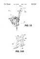
- FIG. 13is an isolated view of a portion of that shown in FIG. 12.
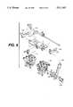
- FIG. 14is an exploded view of that shown in FIG. 12.
- FIG. 14Ais a close-up view of FIG. 14.
- FIG. 15is a pictorial view of an alternate joystick control which may be used in conjunction with the overall mowing apparatus of FIG. 1.
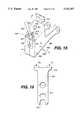
- FIG. 16is a top plan view of a step plate or "dog bone” accounting to the present invention.
- This lawn mower 10includes an engine 12 (typically an internal combustion engine), a pair of front wheels 14, a left rear drive wheel 16, a right rear drive wheel 17, a handle assembly 18 (including a trim control subassembly 20), a grass deflector 22, a cutter engagement lever 24, a belt cover 23, a gasoline container 25, and an oil reservoir 21.
- engine 12typically an internal combustion engine
- front wheels 14typically a pair of front wheels 14, a left rear drive wheel 16, a right rear drive wheel 17, a handle assembly 18 (including a trim control subassembly 20), a grass deflector 22, a cutter engagement lever 24, a belt cover 23, a gasoline container 25, and an oil reservoir 21.
- an operator's right and left hands 26, 28,may be used to control the right and left speed control handles, 30, 32, respectively, as well as the joystick lever 36, and the operator presence bar 38 which is directly behind the upper handlebar 40.
- the operator presence bar 38must be in its "forward" position biased against the rear side of upper handlebar 40, in order for the engine to drive the drive wheels.
- the enginemay be disconnected from its ignition source through suitable electric wiring known in the art.
- the maximum forward speed of either of the drive wheelsmy be adjusted.
- the operatormay draw back (against a spring bias force) upon both of the handles (as shown in FIG. 2) in order to slow down the fight or left drive wheels from the maximum set forward speed positions.
- the wheelsmay be brought to rest at a "neutral" position, and then into reverse.
- the mowermay be operated such that it has a "zero turning radius” (ZTR), or in other words the mower can rotate about a vertical axis located substantially between the drive wheels.
- ZTRzero turning radius
- the set maximum forward speeds of the two wheelsmay be "trimmed", as discussed in later detail.
- a latch 42(See FIG. 5) will pivot rearwardly by a spring to force, and will then prevent either of the handles from going into their forward position until a disengagement lever 44 is pulled upwardly as shown in FIG. 7.
- the handle assembly 18itself includes a trim control subassembly 20, right and left steering control handles 30, 32, an operator presence control bar 38, and a handlebar 40.
- the trim controlincludes a grip 52, a joystick shaft 54, fight and left stop pins 56, 57, a right frame member 60, a left frame member 62, a template member 64, itself including an arcuate slot 66, and two pin holes which slidably accept the two stop pins 56, 57.
- the joystick subassemblylikewise includes a friction plate 70, attached to a console 72 (See FIG. 5). Referring back to FIG.
- the trim control subassembly 20also includes a cross bolt 74, which passes through a compression spring 76 (which provides biasing), through washers 78, frame member 60, a sleeve 82, the left frame member 62 and is captured at the opposite end by nut 86. As discussed later in further detail, the trim control subassembly 20 is allowed to pivot about a substantially horizontal axis relative to the frame of the mower.
- Park lock control rod assembly 67is attached to the fight and left frame members 60, 62, by another crossbolt 88, which passes through the frame members, the upper end 89 of the park lock control rod assembly 67, a washer 90, a sleeve 92, and is captured at its opposite end by a nut 94.
- the lower end of the joystickis captured by a bolt 96 which passes through a hole in the template 64, then passes through the joystick member, through washers, and is captured by a nut.
- a bolt 96which passes through a hole in the template 64, then passes through the joystick member, through washers, and is captured by a nut.
- the joystick member 36is spring-biased against the template 64 by means of a bolt 98, which passes through an arcuate slot 100 in template 64, through a hole in the joystick, through a compression spring 102 which provides a biasing force, and through a washer 104 to be captured finally by a nut.
- the compression spring 102provides a biasing force causing friction between the innermost washer 78 and the friction plate 70 attached to the handle of the mower, such that the joystick subassembly may be pivoted forwardly and rearwardly (about the longitudinal axis of bolt 74) against the frictional force, but the friction preferably provides sufficient force to maintain the joystick subassembly in its set or chosen position once pivoted.
- the handle member 40By moving the right and left speed control handles 30, 32, the right and left control rods 110, 112 are moved substantially along their longitudinal axes. These rods are attached to pivoting pump arms such as the right pump arm 124 illustrated in FIG. 6 and left pump arm 125 shown in FIG. 9 these pump arms are attached to trunnion shafts which control valves within the pumps. It may be understood that by rotating the trunnion shafts in one "forward" direction from a "neutral" position (no fluid flow) through an internal valve structure the pump may direct flow through on fluid line to the fluid motors to create forward movement. By rotating the shafts in an opposite "reverse” direction, flow may be directed through a second set of lines to create reverse movement. Therefore the handles control the amount and direction of hydraulic fluid flow to the hydraulic pumps which drive wheels 17, 16, respectfully.
- the joystick 36includes an inclined or "cam” portion 36 which is preferably in contact at all times with the rounded heads of the stop pins, due to spring force which tend to push both handles 30, 32, forwardly. It may also be understood that the rearwardly-directed ends of the stop pins act as “stops” which contact tabs (See FIG. 7) which are fixed to the speed control handles 30, 32, respectively.
- the longitudinal stop pin axesare both above the pivoting axis of the joystick. As the joystick is pivoted side-to-side along a "pivoting" axis, the inclined surface causes the pins to slide in opposing directions relative to each other along their longitudinal axes. For example, if the joystick 36 is moved to the left as shown in FIG.
- the left stop pinwill be urged rearwardly by a force from the inclined surface, and the right stop pin will be allowed to move forward as more room is available, thus providing a stop for the left side steering control handle which is more rearward than that for the right side steering control handle, when both handles are not being grasped by the operator. Therefore, it may be understood that the left side steering control handle will stop before the fight side handle will.
- a latching feature provided by the inventionis illustrated.
- the crux of this latching mechanismis providing by a latching element 42, which includes a pair of stops one being a right stop 120 and the other being a left stop 121. It may be understood that when an operator provides both of handles 30, 32, in either a "neutral” or a "reverse” position, the latching element 42, being spring loaded, is allowed to engage a "latched” position (preventing the handles from going into forward but allowing them to remain in neutral or to be pulled into reverse) which may only be disengaged upon movement of unlatching lever 47 (against the spring load) as shown in FIG. 7.
- right and left hydraulic pumps 16, 17are illustrated. Also illustrated are right and left park lock template members 114, 115.
- the right and left park lock template memberseach include arcuate slots 119.
- a tie rod assembly 67is attached to the pivoting trim control assembly.
- the lower end of this tie rodis attached to a pivoting bar member 75 (see also FIG. 6), which pivots substantially along a substantially horizontal axis, as the joystick is pivoted forward and rearward.
- This memberhas attached at each end fight and left pivoting park lock template members 114, 115, respectively, which pivot along with the pivoting bar member 75, but also each may be adjusted by means of threaded members such as 97. It should be understood that the threaded members fix the park lock template members to the pivoting bar member, but also allow for relative adjustment.
- the right and left park lock template members 114, 115each include an arcuate slot 119, which are configured to accept corresponding roller members which as shown in FIG. 9 which are rotatably attached to right and left pump arms 124, 125, which are attached to trunnion shafts which control valves (not shown) in the pumps, which as discussed above control fluid flow to the corresponding hydraulic motors which drive the wheels.
- the mowermay be stopped in different ways.
- One wayis possible by using the joystick. By moving the joystick to the "neutral” position, by a series of rods, linkages, slots and notches, the trunnion shafts of both pumps may be locked in their "neutral” position, as described above.
- the operator presence barshould be depressed against the handlebar.
- the blade clutch control 24should then be engaged to its "ON" or down position such as shown in phantom in FIG. 11.
- the joystickshould then be moved forward to select a slow travel speed. This simultaneously moves forward the two stops on the steering control handles. While holding the steering control handles in neutral, the neutral latch should be released by pushing the latch rearward. Simultaneously (and slowly) both steering control handles should then be released, causing them to move forward by the action of spring members and eventually to contact the stop pins.
- the joystickmay then be further adjusted forwardly (more speed) or rearwardly (less speed) to a comfortable level. The operator should then proceed to go forward while allowing the mower to go in a straight line (if preferred). If the mower tends to veer towards the left or right, it can then be brought into a straight path by moving the joystick side-to-side.
- the mowershould first be situated upon flat terrain. If the mower is in forward, both steering control members should then be squeezed until the neutral latch is engaged. The blade clutch control should then be positioned in its "OFF” or disengaged position. The joystick should then be centered and pulled back firmly to its "park lock” position. The operator presence control may then be released and the mower engine will continue to run.
- FIGS. 12-14an alternate operator control configuration is shown, which may be referred to as a "pistol grip” configuration 150 and can replace the “loop handle” configuration shown in FIG. 1. It should be under that this configuration provides an alternate means to control movement of the right and left speed control rods 110, 112, and the park lock control rod assembly 67. As in the previously-discussed "loop" handle control configuration, control of these rods provides control of the speed and direction of rotation of the drive wheels.
- trim control subassembly 20 including a joystick 36is substantially similar in construction and operation to the unit 20 discussed previously and shown in FIG. 2.
- left and right speed control levers 151,152operate and are configured in a similar manner.
- left grip lever 151will be used as an example.
- Left lever 151is pivotably attached to a handlebar member 157 along a substantially horizontal axis substantially perpendicular to straight-forward travel of the machine.
- a linkage 162(See also FIG. 14) has its rear end attached to right speed control lever 152 and its front end attached to a left control linkage assembly 164.
- the left control linkage assembly 164is substantially rigid and includes a sleeve 165, a stop flange 166 rigidly attached to the sleeve 165, and a speed control flange 167 also rigidly attached to the sleeve 165.
- the sleeve 165is rotatably mounted on a rod 169, and the speed control flange 167 is also attached to a left speed control rod 112 (see FIG. 12) which is similar in configuration and operation to the element 112 previously discussed.
- the control rod 112tends to be drawn rearwardly slowing and ultimately reversing travel of the left drive wheel.
- the stop flange 166is allowed to move forwardly under spring biasing until it is stopped by the presence of the left stop pin, which is adjustable as previously discussed.
- the "pistol grip” control configurationincludes “park lock” and “neutral latch” features.
- the park lock featureis similar to that shown in conjunction with FIG. 1, however the "neutral latch” is slightly different.
- the neutral latchis engaged when both speed control rods are in either their “neutral” or “reverse” positions.
- a thumb-operable neutral latch release lever 155is used through a linkage 156 to operate a neutral latch release assembly 170, which includes an elongate rod 171 and a release tab 172 rigidly attached thereto.
- the assembly 170is pivotably attached relative to the handlebar frame, along the longitudinal axis of the rod 171
- the linkage 156is moved generally rearward, causing the neutral latch release rod assembly 170 generally counterclockwise as the unit is viewed in FIGS. 12 and 14.
- This movementcauses the release tab 172 to contact the tip T of one of the ears 181 (See FIG. 14A) of the latching element 182, which is spring-loaded. Further urging causes both pins 190 to become disengaged from stops defined by the latching element 182. This allows either wheel to be driven forward.
- the blade clutch controlshould be placed in its "OFF” position.
- the joystick 36should then be pulled back into its centered, “park lock” position.
- the engineshould then be started and throttled to an appropriate safe level.
- At least one of the operator presence levers 153, 154should be depressed against its respective handlebar 157, 158.
- the blademay then be engaged.
- the joystick 36may then be moved forward, such as 1/2", selecting a slow speed.
- the neutral latch release lever 155may be released by pulling back with the thumb.
- the joystick 150may be adjusted by, for example, pushing it forwardly to increase forward ground speed. As discussed with respect to the "loop" handle design of FIG. 1, by moving the joystick left-to-right or vice versa, the direction of the machine may be "trimmed".
- both speed control levers 151, 152are simultaneously squeezed such that the levers 151,152, are both past their "neutral” position. This will result in the neutral latch being engaged.
- the blade clutch controlmay be moved to its "OFF” position.
- the joystick 150may then be placed in its center position, and pulled rearwardly to its "park lock” position.
- the throttle controlmay then be slowed and ignition killed.
- the subassembly 200includes a body having left and fight halves 201,202, respectfully, rigidly attached together as known by the art.
- a joystick 203is pivotably mounted about axis "A" by a suitable fastener 204, such that the hand of an operator (not shown) may pivot the joystick side-to-side similar to the action discussed above.
- a stop plate 205is likewise pivotably mounted relative to the body of the subassembly 200, about an axis "B" by a suitable fastener 207 which extends through a hole in the step plate and a hole in the two-part body of the trim control subassembly.
- axes A and Bare coplanar.
- the stop plate 205also referred to as a "dog bone” (see FIG. 16), includes fight and left stops 210, 211, in the form of "ears”, and likewise includes a transverse, "closed” slot 212, and a longitudinal, "open” slot at location 213.
- a limiting fastener 214extends rigidly down from the underside of the top wall of the body of the unit 200 and fits within slot 212 and limits the pivoting range of the stop plate 205 about axis B. The length of the slot 212 determines the amount of steering adjustment or "trim” allowed the mower.
- the limiting fastener 214also serves to provide a frictional engagement between the body 200 and the stop plate 205. It may be understood that this frictional relationship may be varied by adjustment means known in the art. The purpose of the frictional engagement is to keep the stop plate in place notwithstanding vibration, but still to allow relative adjustment of the stop plate by manually overriding the frictional engagement.
- a portion of the joystick 203engages the open slot of the stop plate at location 213.
- pivoting of the joystick 203 about axis Acauses corresponding pivoting of the stop plate 205 about axis B.
- a left-to-right movement of the upper end of joystick 203will cause the rear end of the stop plate 205 to pivot about axis B in a generally right-to-left fashion.
- Left and fight ear-shaped stops 210, 211are configured to provide variably adjustable "rearwardmost stopping surfaces" (similar to those provided by the rear tips of the stop pins 57, 56), which provide stops to the tabs 107, 106 shown in FIGS. 5, 7, 1 or 14A.
- the rearwardmost contact surface of the left stop 210will be moved forwardly, and the rearwardmost contact surface of the right stop 211 will be moved rearwardly (assuming a start from a centered position).
- the joystickis moved left-to-right, the rearwardmost stopping surface of the left stop 210 is moved forward relative to the rearwardmost stopping surface of the right stop 211.
- the joystickis moved right-to-left, the rearwardmost stopping surface of the left stop 210 is moved rearward relative to the rearwardmost stopping surface of the right stop 211. Therefore, it may be seen how the joystick 203 may be used to "trim" a mowing unit 10 such as shown in FIG. 1 in a side-to-side manner.
- holessuch as 220, 221, are used to mount the body of the subassembly relative to the frame and park lock control rod assembly such as shown in FIG. 2.
- the unit 200is pivotably mounted relative to its overall mowing unit along axis C.
- the mowershould be adjusted periodically for maximum efficiency.
- the engineshould be stopped and the joystick should be pulled fully backwards to its "park lock” position.
- both of the neutral lock cavitiesshould fully engage the roller bearings on each pump arm. If such is not the case for a particular pump arm, the adjustment screws 97 (shown in FIG. 9) are provided. By adjusting these screws, the misaligned template members 114 or 115 may be adjusted so that its associated arcuate slot fits on its corresponding roller member.
- a neutral adjustmentis also provided at the pump trunnion shafts through the means of an eccentric mounting bolt 126, as shown in FIG. 9, this eccentric bolt works in cooperation with a template 127, which is attached to each pump arm.
- this eccentric boltworks in cooperation with a template 127, which is attached to each pump arm.
- the eccentric bolts 126By adjusting the eccentric bolts 126, the adjustment can be made to the angular relationship of a pump trunnion shaft relative to the corresponding pump lever. Thus adjustment may be made to cause wheel motion to stop when the "park lock" feature is engaged.
- the above-referenced eccentric boltfits with holes 148 (See FIG. 6) which extend through the left pump arm.
Landscapes
- Life Sciences & Earth Sciences (AREA)
- Environmental Sciences (AREA)
- Harvester Elements (AREA)
Abstract
Description
Claims (11)
Priority Applications (1)
| Application Number | Priority Date | Filing Date | Title |
|---|---|---|---|
| US08/283,710US5511367A (en) | 1993-06-28 | 1994-08-01 | Lawn mower having additinal improved trim featuure |
Applications Claiming Priority (2)
| Application Number | Priority Date | Filing Date | Title |
|---|---|---|---|
| US08/084,031US5488818A (en) | 1993-06-28 | 1993-06-28 | Lawn mower having improved trim feature |
| US08/283,710US5511367A (en) | 1993-06-28 | 1994-08-01 | Lawn mower having additinal improved trim featuure |
Related Parent Applications (1)
| Application Number | Title | Priority Date | Filing Date |
|---|---|---|---|
| US08/084,031Continuation-In-PartUS5488818A (en) | 1993-06-28 | 1993-06-28 | Lawn mower having improved trim feature |
Publications (1)
| Publication Number | Publication Date |
|---|---|
| US5511367Atrue US5511367A (en) | 1996-04-30 |
Family
ID=46249182
Family Applications (1)
| Application Number | Title | Priority Date | Filing Date |
|---|---|---|---|
| US08/283,710Expired - LifetimeUS5511367A (en) | 1993-06-28 | 1994-08-01 | Lawn mower having additinal improved trim featuure |
Country Status (1)
| Country | Link |
|---|---|
| US (1) | US5511367A (en) |
Cited By (34)
| Publication number | Priority date | Publication date | Assignee | Title |
|---|---|---|---|---|
| US5848520A (en)* | 1997-04-28 | 1998-12-15 | Deere & Company | Control for hydrostatic transmissions |
| US6026634A (en)* | 1997-01-21 | 2000-02-22 | Mtd Products Inc | Control system and method for stopping the rotation of a cutting blade when the mower is placed in reverse |
| US6082083A (en)* | 1998-09-18 | 2000-07-04 | The Toro Company | Ground speed control system |
| US6557331B2 (en) | 2001-06-27 | 2003-05-06 | Exmark Manufacturing Company, Inc. | Operator control system for self-propelled vehicles |
| US6644002B2 (en) | 2001-09-25 | 2003-11-11 | Deere & Company | Walk-behind self-propelled power equipment unit with speed control |
| US6668529B2 (en) | 2001-06-27 | 2003-12-30 | Emark Manufacturing Company, Incorporated | Operator control system for self-propelled vehicles |
| US20040031629A1 (en)* | 2002-06-21 | 2004-02-19 | Walker Dean M. | Walk behind mower |
| USD489734S1 (en) | 2003-06-10 | 2004-05-11 | Macauto Industrial Co., Ltd. | Lawn mower |
| US20040093767A1 (en)* | 2002-11-14 | 2004-05-20 | Phillip Thomas E. | Split wireform bail |
| US20050011696A1 (en)* | 2003-07-14 | 2005-01-20 | Clark Equipment Company | Hand controls for small loader |
| US20050183409A1 (en)* | 2004-02-23 | 2005-08-25 | Barrier Scott D. | Control mechanism for zero turning radius mower |
| US20060277884A1 (en)* | 2005-06-10 | 2006-12-14 | Ariens Company | Object detection system for a lawn mower |
| US7159377B2 (en) | 2002-08-27 | 2007-01-09 | M Group, Inc. | Powered appliance and accessory |
| US20070256401A1 (en)* | 2006-04-27 | 2007-11-08 | Yoshihisa Hibi | Drive operation device of walk-behind lawn mower |
| US20080026899A1 (en)* | 2006-07-28 | 2008-01-31 | Robert Carlson | Drive train for a tractor |
| US20090081017A1 (en)* | 2007-09-24 | 2009-03-26 | Clark Equipment Company | Adjustable hand controls for small loader |
| US20100126792A1 (en)* | 2008-11-21 | 2010-05-27 | Kallevig Jeffrey B | Power vehicle incorporating velocity control system |
| US20110000175A1 (en)* | 2009-07-01 | 2011-01-06 | Husqvarna Consumer Outdoor Products N.A. Inc. | Variable speed controller |
| US8096374B1 (en) | 2010-06-30 | 2012-01-17 | Exmark Manufacturing Company, Incorporated | Control system and vehicle incorporating same |
| US8312946B2 (en) | 2009-07-02 | 2012-11-20 | Husqvarna Consumer Outdoor Products N.A., Inc. | Trigger controller |
| US8783391B2 (en) | 2010-09-15 | 2014-07-22 | The Toro Company | Power vehicle with adjustable velocity profiles |
| US9163707B2 (en) | 2011-09-30 | 2015-10-20 | Mtd Products Inc | Method for controlling the speed of a self-propelled walk-behind lawn mower |
| US9403435B2 (en) | 2014-10-14 | 2016-08-02 | Honda Motor Co., Ltd. | Adjustable ground speed control devices, systems, and methods for walk-behind equipment |
| US20160324065A1 (en)* | 2015-05-05 | 2016-11-10 | Chervon (Hk) Limited | Lawn mower and hand pushed power tool |
| USD776721S1 (en)* | 2015-10-02 | 2017-01-17 | The Toro Company | Snowthrower chute control |
| US9743581B1 (en) | 2016-02-09 | 2017-08-29 | Deere & Company | Commercial walk behind mower operator controls |
| EP3329763A1 (en)* | 2016-11-30 | 2018-06-06 | Honda Motor Co., Ltd. | Electric power equipment |
| US10150502B2 (en) | 2014-09-19 | 2018-12-11 | The Toro Company | Linkage adjustment system and vehicle incorporating same |
| US10494019B1 (en) | 2018-05-15 | 2019-12-03 | Cnh Industrial America Llc | System and method for executing straight tracking control of a work vehicle |
| US10709064B2 (en) | 2018-01-31 | 2020-07-14 | The Toro Company | Propulsion control lockout and ground working vehicle incorporating same |
| US20220204070A1 (en)* | 2020-12-25 | 2022-06-30 | Globe (jiangsu) Co., Ltd. | Mower and steering control method thereof |
| US20250221342A1 (en)* | 2012-10-15 | 2025-07-10 | Chervon (Hk) Limited | Gardening tool, particularly a mower |
| US12358549B2 (en) | 2021-05-26 | 2025-07-15 | The Toro Company | Drive control system for utility vehicle |
| USD1098205S1 (en)* | 2024-10-11 | 2025-10-14 | Deere & Company | Grass mowing machine console |
Citations (46)
| Publication number | Priority date | Publication date | Assignee | Title |
|---|---|---|---|---|
| US2329372A (en)* | 1940-08-05 | 1943-09-14 | Lester C Hitch | Power lawn mower |
| US2523014A (en)* | 1947-07-15 | 1950-09-19 | Herbert L Gooch | Hydraulic mower |
| US2588004A (en)* | 1948-06-25 | 1952-03-04 | Earl W Holmes | Control means for hydraulically operated weed and brush cutters |
| US2601752A (en)* | 1947-08-08 | 1952-07-01 | Rose Alfred German | Power-driven apparatus |
| US2766834A (en)* | 1953-10-05 | 1956-10-16 | George K Boyer | Valve for simultaneous or selective control of mower traction motors |
| US2941609A (en)* | 1956-07-09 | 1960-06-21 | Dowty Hydraulic Units Ltd | Steering of tracked vehicles |
| US3306385A (en)* | 1960-08-19 | 1967-02-28 | Dowty Hydraulic Units Ltd | Vehicle drive and steering system |
| US3323607A (en)* | 1965-03-12 | 1967-06-06 | Komatsu Mfg Co Ltd | Combined speed control and steering device for vehicles |
| US3528519A (en)* | 1967-03-23 | 1970-09-15 | Hesston Corp | Speed,steering and direction control for vehicles |
| US3540220A (en)* | 1968-03-26 | 1970-11-17 | Eaton Yale & Towne | Hydrostatic transmission control system |
| US3541877A (en)* | 1969-01-23 | 1970-11-24 | Richard D Houk | Single lever control for coordinating multiple motion transmitting devices |
| US3613817A (en)* | 1969-10-28 | 1971-10-19 | Sperry Rand Corp | Linkage mechanism actuating hydrostatic transmissions separately driving the front wheels of a tractor |
| US3616869A (en)* | 1969-10-13 | 1971-11-02 | Excel Ind | Propulsion, steering, and braking system for vehicles |
| US3620096A (en)* | 1968-08-28 | 1971-11-16 | Gianni Scolari | Single maneuvering level control for tracked vehicles |
| US3816985A (en)* | 1972-01-25 | 1974-06-18 | Hahn Inc | Turf maintenance machine |
| US3876021A (en)* | 1974-01-21 | 1975-04-08 | Owatonna Mfg Co | Drive control apparatus for vehicles |
| US3891042A (en)* | 1974-01-21 | 1975-06-24 | Gerald W Braun | Control arrangement for a hydraulically powered vehicle |
| US3946543A (en)* | 1971-12-10 | 1976-03-30 | Templeton William E | Power mower with hydraulic drive |
| US4043416A (en)* | 1975-11-26 | 1977-08-23 | Clark Equipment Company | Skid-steered tractor vehicle combined steering lever and auxiliary control with self-centering mechanism |
| US4085512A (en)* | 1976-12-27 | 1978-04-25 | The Boeing Company | Lumber cutting measurement apparatus and method |
| US4146105A (en)* | 1977-05-13 | 1979-03-27 | Wisconsin Marine, Inc. | Lawn mower |
| US4152950A (en)* | 1977-05-10 | 1979-05-08 | Incom International Inc. | Differential and push-pull control system |
| US4213484A (en)* | 1978-05-30 | 1980-07-22 | Caterpillar Tractor Co. | Single handle control apparatus |
| US4301881A (en)* | 1979-05-08 | 1981-11-24 | Griffin Hugh A | Vehicle drive system |
| US4321980A (en)* | 1980-07-14 | 1982-03-30 | J. I. Case Company | Mono stick assembly with adjustable creep control |
| US4327539A (en)* | 1980-12-16 | 1982-05-04 | The Toro Company | Control system for power equipment |
| US4487006A (en)* | 1983-04-15 | 1984-12-11 | Scag Dane T | Lawn mower |
| US4572019A (en)* | 1983-03-22 | 1986-02-25 | Nippon Cable System, Inc. | Control device for control cables |
| US4580455A (en)* | 1982-01-01 | 1986-04-08 | Conchemco, Incorporated | Locking mechanism for blade clutch control assembly |
| US4667459A (en)* | 1985-03-14 | 1987-05-26 | Roper Corporation | Two action control for power mowers |
| US4736647A (en)* | 1985-12-03 | 1988-04-12 | Kubota, Ltd. | Valve control structure for working vehicle |
| US4753062A (en)* | 1987-06-11 | 1988-06-28 | Capro, Inc. | Lawn mower and safety control therefor |
| US4787195A (en)* | 1987-06-17 | 1988-11-29 | Ferris Industries, Inc. | Power lawnmower with hydrostatic drive |
| US4799398A (en)* | 1986-06-10 | 1989-01-24 | Mikasa Sangyo Co., Ltd. | Safety device for control lever of construction machines |
| US4809796A (en)* | 1986-10-24 | 1989-03-07 | Kanzaki Kokyukoki Mfg. Co. Ltd. | Transmission system for working vehicles |
| US4835949A (en)* | 1983-05-02 | 1989-06-06 | Outboard Marine Corporation | Operator presence control for self-propelled implements |
| US4885903A (en)* | 1988-07-27 | 1989-12-12 | Scag Dane T | Safety interlock for lawn mowers |
| US4920733A (en)* | 1989-10-05 | 1990-05-01 | Berrios Joseph E | Self-propelled, walk-behind, hydraulic motor-operated mower |
| US4930369A (en)* | 1987-07-09 | 1990-06-05 | Wescon Products Company | Radial ground drive and blade clutch control for lawnmower |
| US4991382A (en)* | 1989-08-30 | 1991-02-12 | Scag Power Equipment, Inc. | Lawn mower |
| US4998948A (en)* | 1989-12-04 | 1991-03-12 | Scag Power Equipment, Inc. | Lawn mower |
| US5020308A (en)* | 1990-03-12 | 1991-06-04 | Deere & Company | Self-propelled steerable walk behind mower linkage |
| US5042239A (en)* | 1990-04-06 | 1991-08-27 | Scag Power Equipment, Inc. | Power transmission and steering apparatus for vehicles |
| US5131483A (en)* | 1991-01-28 | 1992-07-21 | Shivvers, Inc. | Single lever control |
| US5146735A (en)* | 1990-06-29 | 1992-09-15 | Fuqua Industries, Inc. | Lawn mower drive and control systems |
| US5375674A (en)* | 1993-04-13 | 1994-12-27 | Mtd Products Inc. | Operator control for lawn and garden vehicles |
- 1994
- 1994-08-01USUS08/283,710patent/US5511367A/ennot_activeExpired - Lifetime
Patent Citations (47)
| Publication number | Priority date | Publication date | Assignee | Title |
|---|---|---|---|---|
| US2329372A (en)* | 1940-08-05 | 1943-09-14 | Lester C Hitch | Power lawn mower |
| US2523014A (en)* | 1947-07-15 | 1950-09-19 | Herbert L Gooch | Hydraulic mower |
| US2601752A (en)* | 1947-08-08 | 1952-07-01 | Rose Alfred German | Power-driven apparatus |
| US2588004A (en)* | 1948-06-25 | 1952-03-04 | Earl W Holmes | Control means for hydraulically operated weed and brush cutters |
| US2766834A (en)* | 1953-10-05 | 1956-10-16 | George K Boyer | Valve for simultaneous or selective control of mower traction motors |
| US2941609A (en)* | 1956-07-09 | 1960-06-21 | Dowty Hydraulic Units Ltd | Steering of tracked vehicles |
| US3306385A (en)* | 1960-08-19 | 1967-02-28 | Dowty Hydraulic Units Ltd | Vehicle drive and steering system |
| US3323607A (en)* | 1965-03-12 | 1967-06-06 | Komatsu Mfg Co Ltd | Combined speed control and steering device for vehicles |
| US3528519A (en)* | 1967-03-23 | 1970-09-15 | Hesston Corp | Speed,steering and direction control for vehicles |
| US3540220A (en)* | 1968-03-26 | 1970-11-17 | Eaton Yale & Towne | Hydrostatic transmission control system |
| US3620096A (en)* | 1968-08-28 | 1971-11-16 | Gianni Scolari | Single maneuvering level control for tracked vehicles |
| US3541877A (en)* | 1969-01-23 | 1970-11-24 | Richard D Houk | Single lever control for coordinating multiple motion transmitting devices |
| US3616869A (en)* | 1969-10-13 | 1971-11-02 | Excel Ind | Propulsion, steering, and braking system for vehicles |
| US3613817A (en)* | 1969-10-28 | 1971-10-19 | Sperry Rand Corp | Linkage mechanism actuating hydrostatic transmissions separately driving the front wheels of a tractor |
| US3946543A (en)* | 1971-12-10 | 1976-03-30 | Templeton William E | Power mower with hydraulic drive |
| US3816985A (en)* | 1972-01-25 | 1974-06-18 | Hahn Inc | Turf maintenance machine |
| US3876021A (en)* | 1974-01-21 | 1975-04-08 | Owatonna Mfg Co | Drive control apparatus for vehicles |
| US3891042A (en)* | 1974-01-21 | 1975-06-24 | Gerald W Braun | Control arrangement for a hydraulically powered vehicle |
| US4043416A (en)* | 1975-11-26 | 1977-08-23 | Clark Equipment Company | Skid-steered tractor vehicle combined steering lever and auxiliary control with self-centering mechanism |
| US4085512A (en)* | 1976-12-27 | 1978-04-25 | The Boeing Company | Lumber cutting measurement apparatus and method |
| US4152950A (en)* | 1977-05-10 | 1979-05-08 | Incom International Inc. | Differential and push-pull control system |
| US4146105A (en)* | 1977-05-13 | 1979-03-27 | Wisconsin Marine, Inc. | Lawn mower |
| US4213484A (en)* | 1978-05-30 | 1980-07-22 | Caterpillar Tractor Co. | Single handle control apparatus |
| US4301881A (en)* | 1979-05-08 | 1981-11-24 | Griffin Hugh A | Vehicle drive system |
| US4321980A (en)* | 1980-07-14 | 1982-03-30 | J. I. Case Company | Mono stick assembly with adjustable creep control |
| US4327539A (en)* | 1980-12-16 | 1982-05-04 | The Toro Company | Control system for power equipment |
| US4580455A (en)* | 1982-01-01 | 1986-04-08 | Conchemco, Incorporated | Locking mechanism for blade clutch control assembly |
| US4572019A (en)* | 1983-03-22 | 1986-02-25 | Nippon Cable System, Inc. | Control device for control cables |
| US4487006A (en)* | 1983-04-15 | 1984-12-11 | Scag Dane T | Lawn mower |
| US4835949A (en)* | 1983-05-02 | 1989-06-06 | Outboard Marine Corporation | Operator presence control for self-propelled implements |
| US4667459A (en)* | 1985-03-14 | 1987-05-26 | Roper Corporation | Two action control for power mowers |
| US4736647A (en)* | 1985-12-03 | 1988-04-12 | Kubota, Ltd. | Valve control structure for working vehicle |
| US4799398A (en)* | 1986-06-10 | 1989-01-24 | Mikasa Sangyo Co., Ltd. | Safety device for control lever of construction machines |
| US4809796A (en)* | 1986-10-24 | 1989-03-07 | Kanzaki Kokyukoki Mfg. Co. Ltd. | Transmission system for working vehicles |
| US4753062A (en)* | 1987-06-11 | 1988-06-28 | Capro, Inc. | Lawn mower and safety control therefor |
| US4787195A (en)* | 1987-06-17 | 1988-11-29 | Ferris Industries, Inc. | Power lawnmower with hydrostatic drive |
| US4930369A (en)* | 1987-07-09 | 1990-06-05 | Wescon Products Company | Radial ground drive and blade clutch control for lawnmower |
| US4885903A (en)* | 1988-07-27 | 1989-12-12 | Scag Dane T | Safety interlock for lawn mowers |
| US4991382A (en)* | 1989-08-30 | 1991-02-12 | Scag Power Equipment, Inc. | Lawn mower |
| US4920733A (en)* | 1989-10-05 | 1990-05-01 | Berrios Joseph E | Self-propelled, walk-behind, hydraulic motor-operated mower |
| US4998948A (en)* | 1989-12-04 | 1991-03-12 | Scag Power Equipment, Inc. | Lawn mower |
| US5020308A (en)* | 1990-03-12 | 1991-06-04 | Deere & Company | Self-propelled steerable walk behind mower linkage |
| US5042239A (en)* | 1990-04-06 | 1991-08-27 | Scag Power Equipment, Inc. | Power transmission and steering apparatus for vehicles |
| US5146735A (en)* | 1990-06-29 | 1992-09-15 | Fuqua Industries, Inc. | Lawn mower drive and control systems |
| US5131483A (en)* | 1991-01-28 | 1992-07-21 | Shivvers, Inc. | Single lever control |
| US5279376A (en)* | 1991-01-28 | 1994-01-18 | Shivvers, Incorporated | Force neutralizing mechanism for a single lever control |
| US5375674A (en)* | 1993-04-13 | 1994-12-27 | Mtd Products Inc. | Operator control for lawn and garden vehicles |
Cited By (48)
| Publication number | Priority date | Publication date | Assignee | Title |
|---|---|---|---|---|
| US6026634A (en)* | 1997-01-21 | 2000-02-22 | Mtd Products Inc | Control system and method for stopping the rotation of a cutting blade when the mower is placed in reverse |
| US5848520A (en)* | 1997-04-28 | 1998-12-15 | Deere & Company | Control for hydrostatic transmissions |
| US6082083A (en)* | 1998-09-18 | 2000-07-04 | The Toro Company | Ground speed control system |
| US6557331B2 (en) | 2001-06-27 | 2003-05-06 | Exmark Manufacturing Company, Inc. | Operator control system for self-propelled vehicles |
| US20030192295A1 (en)* | 2001-06-27 | 2003-10-16 | Exmark Manufacturing Company, Incorporated | Operator control system for self-propelled vehicles |
| US6668529B2 (en) | 2001-06-27 | 2003-12-30 | Emark Manufacturing Company, Incorporated | Operator control system for self-propelled vehicles |
| US6951092B2 (en)* | 2001-06-27 | 2005-10-04 | Exmark Manufacturing Company, Incorporated | Operator control system for self-propelled vehicles |
| US6644002B2 (en) | 2001-09-25 | 2003-11-11 | Deere & Company | Walk-behind self-propelled power equipment unit with speed control |
| US6935446B2 (en)* | 2002-06-21 | 2005-08-30 | Walker Manufacturing Company | Walk behind mower |
| US20040031629A1 (en)* | 2002-06-21 | 2004-02-19 | Walker Dean M. | Walk behind mower |
| US7159377B2 (en) | 2002-08-27 | 2007-01-09 | M Group, Inc. | Powered appliance and accessory |
| US6745548B1 (en) | 2002-11-14 | 2004-06-08 | Ariens Company | Split wireform bail |
| US20040093767A1 (en)* | 2002-11-14 | 2004-05-20 | Phillip Thomas E. | Split wireform bail |
| USD489734S1 (en) | 2003-06-10 | 2004-05-11 | Macauto Industrial Co., Ltd. | Lawn mower |
| US20050011696A1 (en)* | 2003-07-14 | 2005-01-20 | Clark Equipment Company | Hand controls for small loader |
| US7059434B2 (en) | 2003-07-14 | 2006-06-13 | Clark Equipment Company | Hand controls for small loader |
| US20050183409A1 (en)* | 2004-02-23 | 2005-08-25 | Barrier Scott D. | Control mechanism for zero turning radius mower |
| US7467677B2 (en)* | 2004-02-23 | 2008-12-23 | Barrier Scott D | Control mechanism for zero turning radius mower |
| US20060277884A1 (en)* | 2005-06-10 | 2006-12-14 | Ariens Company | Object detection system for a lawn mower |
| US20070256401A1 (en)* | 2006-04-27 | 2007-11-08 | Yoshihisa Hibi | Drive operation device of walk-behind lawn mower |
| US20080026899A1 (en)* | 2006-07-28 | 2008-01-31 | Robert Carlson | Drive train for a tractor |
| US8037952B2 (en) | 2007-09-24 | 2011-10-18 | Clark Equipment Company | Adjustable hand controls for small loader |
| US20090081017A1 (en)* | 2007-09-24 | 2009-03-26 | Clark Equipment Company | Adjustable hand controls for small loader |
| US8047310B2 (en)* | 2008-11-21 | 2011-11-01 | The Toro Company | Power vehicle incorporating velocity control system |
| US20100126792A1 (en)* | 2008-11-21 | 2010-05-27 | Kallevig Jeffrey B | Power vehicle incorporating velocity control system |
| US20110000175A1 (en)* | 2009-07-01 | 2011-01-06 | Husqvarna Consumer Outdoor Products N.A. Inc. | Variable speed controller |
| US8312946B2 (en) | 2009-07-02 | 2012-11-20 | Husqvarna Consumer Outdoor Products N.A., Inc. | Trigger controller |
| US8096374B1 (en) | 2010-06-30 | 2012-01-17 | Exmark Manufacturing Company, Incorporated | Control system and vehicle incorporating same |
| US9288939B2 (en) | 2010-09-15 | 2016-03-22 | The Toro Company | Power vehicle with adjustable velocity profiles |
| US8783391B2 (en) | 2010-09-15 | 2014-07-22 | The Toro Company | Power vehicle with adjustable velocity profiles |
| US9651138B2 (en) | 2011-09-30 | 2017-05-16 | Mtd Products Inc. | Speed control assembly for a self-propelled walk-behind lawn mower |
| US9163707B2 (en) | 2011-09-30 | 2015-10-20 | Mtd Products Inc | Method for controlling the speed of a self-propelled walk-behind lawn mower |
| US9791037B2 (en) | 2011-09-30 | 2017-10-17 | Mtd Products Inc | Speed control assembly for a self-propelled walk-behind lawn mower |
| US20250221342A1 (en)* | 2012-10-15 | 2025-07-10 | Chervon (Hk) Limited | Gardening tool, particularly a mower |
| US10150502B2 (en) | 2014-09-19 | 2018-12-11 | The Toro Company | Linkage adjustment system and vehicle incorporating same |
| US9403435B2 (en) | 2014-10-14 | 2016-08-02 | Honda Motor Co., Ltd. | Adjustable ground speed control devices, systems, and methods for walk-behind equipment |
| US10433478B2 (en)* | 2015-02-05 | 2019-10-08 | Chervon (Hk) Limited | Lawn mower and hand pushed power tool |
| US20160324065A1 (en)* | 2015-05-05 | 2016-11-10 | Chervon (Hk) Limited | Lawn mower and hand pushed power tool |
| USD776721S1 (en)* | 2015-10-02 | 2017-01-17 | The Toro Company | Snowthrower chute control |
| US9743581B1 (en) | 2016-02-09 | 2017-08-29 | Deere & Company | Commercial walk behind mower operator controls |
| EP3329763A1 (en)* | 2016-11-30 | 2018-06-06 | Honda Motor Co., Ltd. | Electric power equipment |
| US10709064B2 (en) | 2018-01-31 | 2020-07-14 | The Toro Company | Propulsion control lockout and ground working vehicle incorporating same |
| US11013173B2 (en) | 2018-01-31 | 2021-05-25 | The Toro Company | Propulsion control lockout and ground working vehicle incorporating same |
| US10494019B1 (en) | 2018-05-15 | 2019-12-03 | Cnh Industrial America Llc | System and method for executing straight tracking control of a work vehicle |
| US10759476B2 (en) | 2018-05-15 | 2020-09-01 | Cnh Industrial America Llc | System and method for executing straight tracking control of a work vehicle |
| US20220204070A1 (en)* | 2020-12-25 | 2022-06-30 | Globe (jiangsu) Co., Ltd. | Mower and steering control method thereof |
| US12358549B2 (en) | 2021-05-26 | 2025-07-15 | The Toro Company | Drive control system for utility vehicle |
| USD1098205S1 (en)* | 2024-10-11 | 2025-10-14 | Deere & Company | Grass mowing machine console |
Similar Documents
| Publication | Publication Date | Title |
|---|---|---|
| US5511367A (en) | Lawn mower having additinal improved trim featuure | |
| US5488818A (en) | Lawn mower having improved trim feature | |
| US5822961A (en) | Quick adjustment for straight ahead travel for a wheel-steered lawn mower | |
| US4920733A (en) | Self-propelled, walk-behind, hydraulic motor-operated mower | |
| US4991382A (en) | Lawn mower | |
| US4967543A (en) | Lawn mower | |
| US6557331B2 (en) | Operator control system for self-propelled vehicles | |
| AU785332B2 (en) | Walk-behind, self-propelled working machine | |
| US7237629B1 (en) | Zero-turn radius vehicle with steerable front wheels | |
| US5251711A (en) | Lawn mower | |
| US5915487A (en) | Walk-behind traction vehicle having variable speed friction drive transmission | |
| US8087481B2 (en) | Dual lever steering controls with control stops | |
| US20080035394A1 (en) | Drive wheel steering system for lawnmower | |
| US5042238A (en) | Riding lawn mower | |
| US6434917B1 (en) | Mower with combined steering and brake levers | |
| US7013626B1 (en) | Walk behind mower | |
| US20080047246A1 (en) | Variable speed transmission twist-grip throttle control apparatuses and methods for self-propelled mowing machine | |
| US6341479B1 (en) | Hydrostatic drive walk-behind lawn mower | |
| US6668529B2 (en) | Operator control system for self-propelled vehicles | |
| US5651241A (en) | Walk-behind mower controls with dual function control bracket | |
| US7574850B1 (en) | Caster wheel locking system for walk-behind mower | |
| US4493180A (en) | Lawn mower dead man control | |
| US20050183409A1 (en) | Control mechanism for zero turning radius mower | |
| WO1999040499A1 (en) | Cruise bar and method of driving a zero turn lawn tractor | |
| US12239046B2 (en) | Storage lock assembly for lawn mower, zero-turn-radius lawn mower including same, and lawn mower |
Legal Events
| Date | Code | Title | Description |
|---|---|---|---|
| AS | Assignment | Owner name:FUQUA INDUSTRIES, GEORGIA Free format text:ASSIGNMENT OF ASSIGNORS INTEREST;ASSIGNORS:POWERS, JAMES R.;WILDER, JOHN W.;HANCOCK, FRANK H., JR.;AND OTHERS;REEL/FRAME:007266/0563;SIGNING DATES FROM 19940921 TO 19940927 | |
| AS | Assignment | Owner name:ACTAVA GROUP, INC., THE, GEORGIA Free format text:ASSIGNMENT OF ASSIGNORS INTEREST;ASSIGNORS:POWERS, JAMES R.;WILDER, JOHN R.;HANCOCK, FRANK H., JR.;AND OTHERS;REEL/FRAME:007660/0026 Effective date:19950921 | |
| AS | Assignment | Owner name:DEUTSCHE FINANCIAL SERVICES CORPORATION, MISSOURI Free format text:SECURITY AGREEMENT;ASSIGNOR:SNAPPER, INC.;REEL/FRAME:007715/0979 Effective date:19951101 | |
| AS | Assignment | Owner name:MICRON TECHNOLOGY, INC., IDAHO Free format text:ASSIGNMENT OF ASSIGNORS INTEREST;ASSIGNOR:TEKTRONIX, INC.;REEL/FRAME:007715/0974 Effective date:19951003 | |
| STCF | Information on status: patent grant | Free format text:PATENTED CASE | |
| AS | Assignment | Owner name:DEUTSCHE FINANCIAL SERVICE CORPORATION, MISSOURI Free format text:RELEASE OF SECURITY INTEREST;ASSIGNOR:SNAPPER, INC.;REEL/FRAME:008239/0140 Effective date:19961126 Owner name:AMSOUTH BANK OF ALABAMA, ALABAMA Free format text:SECURITY AGREEMENT;ASSIGNOR:SNAPPER, INC.;REEL/FRAME:008239/0719 Effective date:19961126 | |
| AS | Assignment | Owner name:SNAPPER, INC., GEORGIA Free format text:PATENT RELEASE;ASSIGNOR:AMSOUTH BANK OF ALABAMA;REEL/FRAME:009586/0190 Effective date:19981113 Owner name:FLEET CAPITAL CORPORATION, GEORGIA Free format text:ASSIGNMENT OF ASSIGNORS INTEREST;ASSIGNOR:SNAPPER, INC.;REEL/FRAME:009586/0335 Effective date:19981111 | |
| FPAY | Fee payment | Year of fee payment:4 | |
| FEPP | Fee payment procedure | Free format text:PAYOR NUMBER ASSIGNED (ORIGINAL EVENT CODE: ASPN); ENTITY STATUS OF PATENT OWNER: LARGE ENTITY | |
| AS | Assignment | Owner name:SNAPPER PRODUCTS, INC., WISCONSIN Free format text:ASSIGNMENT OF ASSIGNORS INTEREST;ASSIGNOR:SNAPPER, INC.;REEL/FRAME:013599/0563 Effective date:20021127 | |
| AS | Assignment | Owner name:FLEET CAPITAL CORPORATION, AS AGENT, ILLINOIS Free format text:SECURITY AGREEMENT;ASSIGNOR:SMI SNP, INC.(T/B/K/A SNAPPER PRODUCTS, INC.);REEL/FRAME:013663/0887 Effective date:20021127 | |
| REMI | Maintenance fee reminder mailed | ||
| REMI | Maintenance fee reminder mailed | ||
| FPAY | Fee payment | Year of fee payment:8 | |
| SULP | Surcharge for late payment | Year of fee payment:7 | |
| FPAY | Fee payment | Year of fee payment:12 |