US5510977A - Method and apparatus for measuring features of a part or item - Google Patents
Method and apparatus for measuring features of a part or itemDownload PDFInfo
- Publication number
- US5510977A US5510977AUS08/284,397US28439794AUS5510977AUS 5510977 AUS5510977 AUS 5510977AUS 28439794 AUS28439794 AUS 28439794AUS 5510977 AUS5510977 AUS 5510977A
- Authority
- US
- United States
- Prior art keywords
- feature
- equivalent
- geometrical shape
- measurement element
- orientation
- Prior art date
- Legal status (The legal status is an assumption and is not a legal conclusion. Google has not performed a legal analysis and makes no representation as to the accuracy of the status listed.)
- Expired - Fee Related
Links
Images


Classifications
- G—PHYSICS
- G01—MEASURING; TESTING
- G01B—MEASURING LENGTH, THICKNESS OR SIMILAR LINEAR DIMENSIONS; MEASURING ANGLES; MEASURING AREAS; MEASURING IRREGULARITIES OF SURFACES OR CONTOURS
- G01B21/00—Measuring arrangements or details thereof, where the measuring technique is not covered by the other groups of this subclass, unspecified or not relevant
- G01B21/02—Measuring arrangements or details thereof, where the measuring technique is not covered by the other groups of this subclass, unspecified or not relevant for measuring length, width, or thickness
- G01B21/04—Measuring arrangements or details thereof, where the measuring technique is not covered by the other groups of this subclass, unspecified or not relevant for measuring length, width, or thickness by measuring coordinates of points
- G01B21/047—Accessories, e.g. for positioning, for tool-setting, for measuring probes
- G—PHYSICS
- G01—MEASURING; TESTING
- G01B—MEASURING LENGTH, THICKNESS OR SIMILAR LINEAR DIMENSIONS; MEASURING ANGLES; MEASURING AREAS; MEASURING IRREGULARITIES OF SURFACES OR CONTOURS
- G01B5/00—Measuring arrangements characterised by the use of mechanical techniques
- G01B5/004—Measuring arrangements characterised by the use of mechanical techniques for measuring coordinates of points
- G01B5/008—Measuring arrangements characterised by the use of mechanical techniques for measuring coordinates of points using coordinate measuring machines
Definitions
- This inventionrelates generally to a method and apparatus for measuring position and orientation of features of a part or item. More specifically, the present invention relates to a method and apparatus for measuring position and orientation of features of a part or item, using a portable coordinate measuring machine (CMM).
- CCMportable coordinate measuring machine
- the methodology used for measuring sheet metal featuresis complex due to the typically curved and complex nature of these features.
- the complexity of these featuresis compounded by the thinness of the metal sheets which makes it difficult to properly measure the position of edges using conventional measurement techniques.
- One of the two methods most commonly used todayis check fixtures which are assemblages of posts, rests, clamps, etc. onto which the sheet metal part is placed and visual examination is made to seek variations between the hard fixture and the sheet metal part. This method is typically nonanalytical and is prone to significant setup error. It is also fundamentally a subjective process.
- the other method, which is the most commonly used for quality control of sheet metal partsis the checking of a percentage of the parts on a computer controlled CMM. The use of a manual CMM is extremely infrequent. The reasons for this are explained as follows.
- a CMM probeSince a CMM probe requires compensation for its probe thickness, it is necessary to establish vectors, normal to surfaces, and/or edges in order to define a direction of probe compensation. This process usually entails numerous hits.
- a hitis defined as the measurement of a location of the probe. Numerous hits are required in order to define surface vectors; for example, three hits on a surface to define a plane and, therefore, the normal to surface; two hits near an edge to define a normal to an edge.
- This multiplicity of hitsis time consuming and makes the process prone to system crashes.
- a system crash on a computer controlled CMMis usually caused by variations in the part for which the programmed CMM motion is not adapted. This will result in unexpected probe contact with the surface (i.e., crashes) and, therefore, require reprogramming of the system.
- the multiple hits and their planningis also an extremely complex process, usually requiring off-line CMM simulation software and significant trial and error.
- Position in a spacemay be defined by length, width and height which, in engineering terms, is often called an X, Y, Z coordinate.
- the X, Y, Z numbersrepresent the dimensions of length, width and height or three dimensions.
- Three-dimensional objectsare described in terms of position and orientation; that is, not just where an object is but in what direction it points.
- the orientation of an object in spacecan be defined by the position of three points on the object. Orientation can also be described by the angles of alignment of the object in space.
- the X, Y, and Z coordinatescan be most simply measured by three linear scales. In other words, if you lay a scale along the length, width and height of a space, you can measure the position of a point in the space.
- the coordinate measuring machinee.g., the CMM described in U.S. patent application Ser. No. 08/021,949, now U.S. Pat. No. 5,402,582
- the coordinate measuring machinecomprises a multijointed (preferably six joints) manually positionable measuring arm for accurately and easily measuring the position of one or more measurement holes on an equivalent.
- the equivalenthas a handle attached thereto for holding the equivalent in position during measurement.
- the equivalenthas a geometrical shape designed to match a feature of a part or item.
- equivalents having geometrical shapes to match the following featuresan outside corner, a square hole, a rectangular hole, an oval hole, a round or circular hole, an edge and an inside corner may be used.
- the part or item having features to be measuredmay be a sheet metal, such as an automobile panel (prior to or after mounting to an automobile) or any other application for sheet metal (e.g., appliances or enclosures). Further, the part may be comprised of any suitable material, for example, plastic or fiberglass.
- a master or standard reference file for the part and its featuresis generated in CAD (computer aided design) data, as is well known and as such is generally generated prior to the manufacture (i.e., stamping, cutting, bending or punching) of the part.
- the information in the CAD data fileincludes information on exact three-dimensional location, orientation and shape of the part and each of its features. Equivalents are manufactured to match (i.e., conform to) the features of the part to be measured.
- the CMMis positioned within reach of the part.
- a coordinate systemis defined either relative to the part to be measured or to the overall assembly (e.g., a panel mounted on an automobile), as is known.
- the equivalentis held in position at the handle by one hand of an operator. The dimensions of the equivalent and the position of the measurement hole in the equivalent are known and are accounted for by the computer when measurements are taken.
- the probe (which is held by the other hand of the operator) of the CMMis used to digitize the position of measurement hole, thereby digitizing that feature of the part. It will be appreciated that all the features of the part for which measurement is desired are digitized in this manner. These digitized positions for each feature are stored in the computer memory and compared to the reference file. It will be appreciated, that where a CAD reference file is not available, one can be created by measurement of features on a master part (template).
- the present inventionavoids the prior art method's necessity for up to eight or nine separate hits for a typical round ended slot and only a single or double hit is required.
- FIG. 1is a side diagrammatic view depicting the three dimensional measuring system including a coordinate measuring machine (CMM), a controller box and a host computer;
- CMScoordinate measuring machine
- FIGS. 2A-Dare side views of a handle for an equivalent in accordance with the present invention wherein FIG. 2A is a side elevation view thereof, FIG. 2B is another side elevation view thereof partly in cross section, FIG. 2C is still another side elevation view thereof, and FIG. 2D is an end view thereof;
- FIG. 3is a side view of the handle of FIGS. 2A-D connected to an equivalent in accordance with the present invention
- FIGS. 4A-Eare views of an outside corner equivalent in accordance with the present invention wherein FIG. 4A is a first side view thereof, FIG. 4B is bottom view thereof, FIG. 4C is a second side view thereof, FIG. 4D is a rear view thereof, and FIG. 4E is a front view thereof;
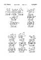
- FIGS. 5A-Care views of a square hole equivalent in accordance with the present invention wherein FIG. 5A is bottom view thereof, FIG. 5B is a side view thereof, and FIG. 5C is a top view thereof;
- FIGS. 6A-Care views of a rectangular hole equivalent in accordance with the present invention wherein FIG. 6A is bottom view thereof, FIG. 6B is a side view thereof, and FIG. 6C is a top view thereof;
- FIGS. 7A-Care views of an oval hole equivalent in accordance with the present invention wherein FIG. 7A is bottom view thereof, FIG. 7B is a side view thereof, and FIG. 7C is a top view thereof;
- FIGS. 8A-Care views of a round or circular hole equivalent in accordance with the present invention wherein FIG. 8A is bottom view thereof, FIG. 8B is a side view thereof, and FIG. 8C is a top view thereof;
- FIGS. 9A-Care views of an edge equivalent in accordance with the present invention wherein FIG. 9A is top view thereof, FIG. 9B is a rear view thereof, and FIG. 9C is a side view thereof;
- FIGS. 10A-Dare views of an inside corner equivalent in accordance with the present invention wherein FIG. 10A is top view thereof, FIG. 10B is a first side view thereof, FIG. 10C is a bottom view thereof, and FIG. 10D is a second side view thereof; and
- FIG. 11is a perspective diagrammatic view of the edge equivalent of FIGS. 9A-C attached to the handle of FIGS. 2A-D positioned on an edge feature of a part being measured by the CMM of FIG. 1 in accordance with a method of the present invention.
- a three dimensional measuring system for use in the present inventiongenerally comprises a coordinate measuring machine (CMM) 10 composed of a manually operated multijointed arm 12 and a support base or post 14, a controller or serial box 16 and a host computer 18. It will be appreciated that CMM 10 electronically communicates with serial box 16 which, in turn, electronically communicates with host computer 18.
- CMMcoordinate measuring machine
- CMM 10includes transducers (e.g., one transducer for each degree of freedom) which gather rotational positioning data and forward this basic data to serial box 16.
- Serial box 16provides a reduction in the overall requirements of host computer 18 to handle certain complex calculations and provides certain preliminary data manipulations.
- Basic transducer datais sent from CMM 10 to serial box 16,
- Serial box 16then processes the raw transducer data on an ongoing basis and responds to the queries of the host computer with the desired three-dimensional positional or orientational information.
- all three components defining the three dimensional measuring system of this inventionare mounted on either a fixed mounting surface using a rigid plate and/or a standard optical measurement instrument thread followed by mounting on a known and standard theodolite mobile stand, such as part no. MWS750 manufactured by Brunson.
- a mobile standis characterized by a stable rolling platform with an extendable vertical tower and with common attachments and locking mechanisms.
- a CMM(e.g., as described above with reference to U.S. patent application Ser. No. 08/021,949, the METRECOM Model: IND-01, other commercially available CMM) is used to measure the position of devices having geometrical shapes which are designed to match features of a work piece (e.g., a formed piece of sheet metal, such as a automobile door panel), these devices are referred to herein as "equivalents" and are discussed more fully below.
- Handle 30comprises an elongated shaft 32 having a rounded end portion 34 and a narrowing tapered end portion 36. A portion of the shaft near end 36 is preferably knurled, as is known. A narrowed shaft portion 38 depends from end 36 and terminates at the distal end 40 thereof with means for attaching an equivalent thereto.
- End 40comprises a flat surface 42 which is disposed at about a forty-five degree angle relative to the center axis 44 of handle 30. This angle is believed to provide a convenient or ergonomically correct position of the handle during use (the handle having an equivalent attached thereto).
- End 40further comprises a second flat surface 46 perpendicularly depending from one end of surface 42.
- a screw mounting hole 48extends through portion 38 and surface 42 with hole 48 being countersunk at the outer surface of portion 38.
- Equivalent 50has a geometrical shape designed to match outside corner features of a work piece.
- Equivalent 50has generally an inverted L shape and comprises a side surface 54, a stepped side surface 56, a top surface 58, a stepped bottom surface 60, a rear surface 62, and a two-way stepped front surface 64.
- Stepped side surface 56is defined by portions 64 and 66.
- Two-way stepped front surface 64is defined by portions 68 and 70, and portions 72 and 74.
- the corner defined by the intersection of portions 72 and 74is a recessed arcuate surface 76 which will allow for minor tolerance variations in the actual corner of the work piece.
- the equivalent featureis defined by portions 66, 72 and 74.
- Rear surface 62has a tapped screw hole 78 therein for accepting screw 52 (FIG. 3).
- a measurement hole 79is provided in side surface 54 and is centered to be in alignment with the corner of the equivalent feature, the function of which will be described hereinafter.
- Equivalent 80comprises a first square portion 82 having a thickness at least equal to the length of surface 42 of handle 30 to assure that the handle is sufficiently cleared from the work piece when attached to the equivalent during measurement.
- Portion 82has four side surfaces 84, 86, 88, 90, an upper surface 92 and a lower surface 94.
- a second smaller square portion 96depends from about the center of the lower surface 94 of portion 82.
- Portion 96has four side surfaces 98, 100, 102, 104 and a lower surface 106. It will be appreciated that the equivalent feature is defined by portion 96.
- Surface 90has a tapped screw hole 108 therein for accepting screw 52 (similar to FIG. 3).
- surface 92 of the equivalentabuts surface 46 of the handle and surface 90 of the equivalent abuts surface 42 of the handle.
- a measurement hole 110is provided in upper surface 92 at about the center thereof, the function of which will be described hereinafter.
- Equivalent 112comprises a first rectangular portion 114 having a thickness at least equal to the length of surface 42 of handle 30 to assure that the handle is sufficiently cleared from the work piece when attached to the equivalent during measurement.
- Portion 114has four side surfaces 116, 118, 120, 122, an upper surface 124 and a lower surface 126.
- a second smaller rectangular portion 128depends from about the center of the lower surface 126 of portion 114.
- Portion 128has four side surfaces 130, 132, 134, 136 and a lower surface 138. It will be appreciated that the equivalent feature is defined by portion 128.
- Surface 122has a tapped screw hole 140 therein for accepting screw 52 (similar to FIG. 3).
- surface 124 of the equivalentabuts surface 46 of the handle and surface 122 of the equivalent abuts surface 42 of the handle.
- Two measurement holes 142, 144are provided in upper surface 124 with the center of each hole being in general alignment with about the center of corresponding side surface 130, 132, the function of the measurement holes will be described hereinafter.
- Equivalent 146comprises a first rectangular portion 148 having a thickness at least equal to the length of surface 42 of handle 30 to assure that the handle is sufficiently cleared from the work piece when attached to the equivalent during measurement.
- Portion 148has four side surfaces 150, 152, 154, 156, an upper surface 158 and a lower surface 160.
- a second smaller oval portion 162depends from about the center of the lower surface 160 of portion 148.
- Portion 162has two side surfaces 164, 166, two curved or arcuate side surfaces 168, 170 and a lower surface 172. It will be appreciated that the equivalent feature is defined by portion 162.
- Surface 154has a tapped screw hole 174 therein for accepting screw 52 (similar to FIG. 3).
- surface 158 of the equivalentabuts surface 46 of the handle and surface 154 of the equivalent abuts surface 42 of the handle.
- Two measurement holes 176, 178are provided in upper surface 124 with a portion of the circumference of each hole being in general alignment with the corresponding curved side surface 168, 170, whereby one half of the circumference of each hole closely approximates and aligns with the curvature of corresponding surface 168, 170, the function of the measurement holes will be described hereinafter.
- Equivalent 180comprises a first cylindrical portion 182 having a thickness at least equal to the length of surface 42 of handle 30 to assure that the handle is sufficiently cleared from the work piece when attached to the equivalent during measurement.
- Portion 182has a circumferential side surface 184, an upper surface 186 and a lower surface 188.
- a second smaller cylindrical portion 190depends from about the center of the lower surface 188 of portion 182.
- Portion 190has a circumferential side surface 192 and a lower surface 194. It will be appreciated that the equivalent feature is defined by portion 190.
- Surface 184has a tapped screw hole 196 therein for accepting screw 52 (similar to FIG. 3).
- surface 186 of the equivalentabuts surface 46 of the handle and surface 184 of the equivalent abuts surface 42 of the handle.
- a measurement hole 198is provided in upper surface 186 at about the center thereof, the function of the measurement holes will be described hereinafter.
- Equivalent 200has generally an inverted L shape and comprises a side surfaces 202 and 204, a top surface 206, a stepped bottom surface 208, a rear surface 210, and a stepped front surface 212.
- Stepped bottom surface 208is defined by portions 214 and 216.
- Stepped front surface 212is defined by portions 218 and 220. It will be appreciated that the equivalent feature is defined by portions 216 and 220.
- Rear surface 210has a tapped screw hole 222 therein for accepting screw 52 (FIG. 3).
- a measurement hole 224is provided in top surface 206 and is centered to be in alignment with the edge of the equivalent feature (i.e., the intersection of portions 216 and 220), the function of which will be described hereinafter.
- Equivalent 226comprises an upper generally triangularly shaped portion 228 and a smaller, lower generally triangularly shaped portion 230.
- Portion 228comprises side surfaces 232, 234 and 236, upper surface 238 and lower surface 240.
- Portion 230depends from surface 240 of portion 228 and comprises side surfaces 242, 244 and 246 and lower surface 248.
- the corner 250 defined by portion 230ground down to allow for minor tolerance variations in the actual corner of the work piece. It will be appreciated that the equivalent feature is defined by portion 230, and more specifically the intersection of sides 242 and 244.
- Surface 236has a tapped screw hole 252 therein for accepting screw 52 (FIG. 3).
- surface 238 of the equivalentabuts surface 46 of the handle and surface 236 of the equivalent abuts surface 42 of the handle.
- a measurement hole 254is provided in upper surface 238 and is centered to be in alignment with the corner of the equivalent feature, the function of which will be described hereinafter.
- Sheet 260may be an automobile panel (prior to or after mounting to an automobile) or any other application for sheet metal (e.g., appliances or enclosures). Further, sheet 260 may be comprised of any suitable material, for example, plastic or fiberglass.
- a master or standard reference file for the sheet metal and its featuresis generated in CAD (computer aided design) data, as is well known and as such is generally generated prior to the manufacture (i.e., stamping, cutting, bending or punching) of sheet metal 260.
- the information in the CAD data fileincludes information on exact three-dimensional location, orientation and shape of the sheet and each of its features.
- CMM 10is positioned within reach of sheet 260.
- a coordinate systemis defined either relative to the sheet (i.e., the item or part to be measured) or the overall assembly of which the sheet is a part thereof (e.g., a panel mounted on an automobile), as is known.
- edge equivalent 200 mounted to handle 30, as described hereinbeforeis shown positioned for measurement of an edge feature 262 of the sheet. The equivalent is held in position at the handle by one hand of an operator. The dimensions of the equivalent and the position of the measurement hole 224 are known and are accounted for by the computer when measurements are taken.
- the probe 264(which is held by the other hand of the operator) of CMM 10 is used to digitize the position of measurement hole 224, thereby digitizing that feature of the sheet. It will be appreciated that the entire edge as well as all other features of the sheet for which measurement is desired are digitized as described above. These digitized positions for each feature are stored in the computer memory and compared to the reference file, whereby the position and orientation of each feature is verified, for example, for quality assurance purposes. It will be appreciated, that where a CAD reference file is not available, one can be created by measurement of features on a master sheet (template or part)using the above described method of the present invention.
- the measurement holes in the present exampleare 0.200 inches in diameter, since the probe of the above-described CMM as a diameter of 0.250 inches. It will be appreciated that the diameter of the measurement holes will be sized in accordance with the probe diameter and that the above is only exemplary.
Landscapes
- Physics & Mathematics (AREA)
- General Physics & Mathematics (AREA)
- A Measuring Device Byusing Mechanical Method (AREA)
- Length Measuring Devices With Unspecified Measuring Means (AREA)
Abstract
Description
This invention relates generally to a method and apparatus for measuring position and orientation of features of a part or item. More specifically, the present invention relates to a method and apparatus for measuring position and orientation of features of a part or item, using a portable coordinate measuring machine (CMM).
The methodology used for measuring sheet metal features is complex due to the typically curved and complex nature of these features. The complexity of these features is compounded by the thinness of the metal sheets which makes it difficult to properly measure the position of edges using conventional measurement techniques. One of the two methods most commonly used today is check fixtures which are assemblages of posts, rests, clamps, etc. onto which the sheet metal part is placed and visual examination is made to seek variations between the hard fixture and the sheet metal part. This method is typically nonanalytical and is prone to significant setup error. It is also fundamentally a subjective process. The other method, which is the most commonly used for quality control of sheet metal parts, is the checking of a percentage of the parts on a computer controlled CMM. The use of a manual CMM is extremely infrequent. The reasons for this are explained as follows.
Since a CMM probe requires compensation for its probe thickness, it is necessary to establish vectors, normal to surfaces, and/or edges in order to define a direction of probe compensation. This process usually entails numerous hits. A hit is defined as the measurement of a location of the probe. Numerous hits are required in order to define surface vectors; for example, three hits on a surface to define a plane and, therefore, the normal to surface; two hits near an edge to define a normal to an edge. This multiplicity of hits is time consuming and makes the process prone to system crashes. A system crash on a computer controlled CMM is usually caused by variations in the part for which the programmed CMM motion is not adapted. This will result in unexpected probe contact with the surface (i.e., crashes) and, therefore, require reprogramming of the system. The multiple hits and their planning is also an extremely complex process, usually requiring off-line CMM simulation software and significant trial and error.
Further, it will be appreciated that everything in the physical world occupies volume or space. Position in a space may be defined by length, width and height which, in engineering terms, is often called an X, Y, Z coordinate. The X, Y, Z numbers represent the dimensions of length, width and height or three dimensions. Three-dimensional objects are described in terms of position and orientation; that is, not just where an object is but in what direction it points. The orientation of an object in space can be defined by the position of three points on the object. Orientation can also be described by the angles of alignment of the object in space. The X, Y, and Z coordinates can be most simply measured by three linear scales. In other words, if you lay a scale along the length, width and height of a space, you can measure the position of a point in the space.
The above-discussed and other problems and deficiencies of the prior art are overcome or alleviated by the method and apparatus for measuring position and orientation of features of a part or item, using a portable coordinate measuring machine is presented. The coordinate measuring machine (e.g., the CMM described in U.S. patent application Ser. No. 08/021,949, now U.S. Pat. No. 5,402,582) comprises a multijointed (preferably six joints) manually positionable measuring arm for accurately and easily measuring the position of one or more measurement holes on an equivalent.
The equivalent has a handle attached thereto for holding the equivalent in position during measurement. The equivalent has a geometrical shape designed to match a feature of a part or item. By way of example, equivalents having geometrical shapes to match the following features; an outside corner, a square hole, a rectangular hole, an oval hole, a round or circular hole, an edge and an inside corner may be used.
The part or item having features to be measured may be a sheet metal, such as an automobile panel (prior to or after mounting to an automobile) or any other application for sheet metal (e.g., appliances or enclosures). Further, the part may be comprised of any suitable material, for example, plastic or fiberglass. A master or standard reference file for the part and its features is generated in CAD (computer aided design) data, as is well known and as such is generally generated prior to the manufacture (i.e., stamping, cutting, bending or punching) of the part. The information in the CAD data file includes information on exact three-dimensional location, orientation and shape of the part and each of its features. Equivalents are manufactured to match (i.e., conform to) the features of the part to be measured. The CMM is positioned within reach of the part. A coordinate system is defined either relative to the part to be measured or to the overall assembly (e.g., a panel mounted on an automobile), as is known. The equivalent is held in position at the handle by one hand of an operator. The dimensions of the equivalent and the position of the measurement hole in the equivalent are known and are accounted for by the computer when measurements are taken. The probe (which is held by the other hand of the operator) of the CMM is used to digitize the position of measurement hole, thereby digitizing that feature of the part. It will be appreciated that all the features of the part for which measurement is desired are digitized in this manner. These digitized positions for each feature are stored in the computer memory and compared to the reference file. It will be appreciated, that where a CAD reference file is not available, one can be created by measurement of features on a master part (template).
The present invention avoids the prior art method's necessity for up to eight or nine separate hits for a typical round ended slot and only a single or double hit is required.
The above-discussed and other features and advantages of the present invention will be appreciated and understood by those skilled in the art from the following detailed description and drawings.
Referring to the drawings, wherein like elements are numbered alike in the several Figures:
FIG. 1 is a side diagrammatic view depicting the three dimensional measuring system including a coordinate measuring machine (CMM), a controller box and a host computer;
FIGS. 2A-D are side views of a handle for an equivalent in accordance with the present invention wherein FIG. 2A is a side elevation view thereof, FIG. 2B is another side elevation view thereof partly in cross section, FIG. 2C is still another side elevation view thereof, and FIG. 2D is an end view thereof;
FIG. 3 is a side view of the handle of FIGS. 2A-D connected to an equivalent in accordance with the present invention;
FIGS. 4A-E are views of an outside corner equivalent in accordance with the present invention wherein FIG. 4A is a first side view thereof, FIG. 4B is bottom view thereof, FIG. 4C is a second side view thereof, FIG. 4D is a rear view thereof, and FIG. 4E is a front view thereof;
FIGS. 5A-C are views of a square hole equivalent in accordance with the present invention wherein FIG. 5A is bottom view thereof, FIG. 5B is a side view thereof, and FIG. 5C is a top view thereof;
FIGS. 6A-C are views of a rectangular hole equivalent in accordance with the present invention wherein FIG. 6A is bottom view thereof, FIG. 6B is a side view thereof, and FIG. 6C is a top view thereof;
FIGS. 7A-C are views of an oval hole equivalent in accordance with the present invention wherein FIG. 7A is bottom view thereof, FIG. 7B is a side view thereof, and FIG. 7C is a top view thereof;
FIGS. 8A-C are views of a round or circular hole equivalent in accordance with the present invention wherein FIG. 8A is bottom view thereof, FIG. 8B is a side view thereof, and FIG. 8C is a top view thereof;
FIGS. 9A-C are views of an edge equivalent in accordance with the present invention wherein FIG. 9A is top view thereof, FIG. 9B is a rear view thereof, and FIG. 9C is a side view thereof;
FIGS. 10A-D are views of an inside corner equivalent in accordance with the present invention wherein FIG. 10A is top view thereof, FIG. 10B is a first side view thereof, FIG. 10C is a bottom view thereof, and FIG. 10D is a second side view thereof; and
FIG. 11 is a perspective diagrammatic view of the edge equivalent of FIGS. 9A-C attached to the handle of FIGS. 2A-D positioned on an edge feature of a part being measured by the CMM of FIG. 1 in accordance with a method of the present invention.
Referring first to FIG. 1, a three dimensional measuring system for use in the present invention generally comprises a coordinate measuring machine (CMM) 10 composed of a manually operatedmultijointed arm 12 and a support base or post 14, a controller orserial box 16 and ahost computer 18. It will be appreciated that CMM 10 electronically communicates withserial box 16 which, in turn, electronically communicates withhost computer 18.
CMM 10 includes transducers (e.g., one transducer for each degree of freedom) which gather rotational positioning data and forward this basic data toserial box 16.Serial box 16 provides a reduction in the overall requirements ofhost computer 18 to handle certain complex calculations and provides certain preliminary data manipulations. Basic transducer data is sent from CMM 10 toserial box 16,Serial box 16 then processes the raw transducer data on an ongoing basis and responds to the queries of the host computer with the desired three-dimensional positional or orientational information.
Preferably, all three components defining the three dimensional measuring system of this invention (e.g., CMM 10,serial box 16 and host computer 18) are mounted on either a fixed mounting surface using a rigid plate and/or a standard optical measurement instrument thread followed by mounting on a known and standard theodolite mobile stand, such as part no. MWS750 manufactured by Brunson. Such a mobile stand is characterized by a stable rolling platform with an extendable vertical tower and with common attachments and locking mechanisms.
While the above generally describes the coordinate measuring machine of U.S. patent application Ser. No. 08/021,949, now U.S. Pat. No. 5,402,582, which is incorporated herein by reference, such a high accuracy measuring device, may in some applications not be required. In such applications the aforementioned METRECOM MODEL: IND-01 Coordinate Measuring Machine commercially available from FARO Technologies, Inc., Industrial Division, 125 Technology Park, Lake Mary, Fla. 32746 (assignee of the present invention) may be employed. The METRECOM system performs the same functions as the above described system, however with reduced accuracy and at a reduced cost.
A CMM (e.g., as described above with reference to U.S. patent application Ser. No. 08/021,949, the METRECOM Model: IND-01, other commercially available CMM) is used to measure the position of devices having geometrical shapes which are designed to match features of a work piece (e.g., a formed piece of sheet metal, such as a automobile door panel), these devices are referred to herein as "equivalents" and are discussed more fully below.
Referring to FIGS. 2A-D, a universal handle assembly for use with various equivalents is shown generally at 30.Handle 30 comprises an elongated shaft 32 having a rounded end portion 34 and a narrowingtapered end portion 36. A portion of the shaft nearend 36 is preferably knurled, as is known. A narrowedshaft portion 38 depends fromend 36 and terminates at thedistal end 40 thereof with means for attaching an equivalent thereto.End 40 comprises aflat surface 42 which is disposed at about a forty-five degree angle relative to the center axis 44 ofhandle 30. This angle is believed to provide a convenient or ergonomically correct position of the handle during use (the handle having an equivalent attached thereto).End 40 further comprises a secondflat surface 46 perpendicularly depending from one end ofsurface 42. Ascrew mounting hole 48 extends throughportion 38 andsurface 42 withhole 48 being countersunk at the outer surface ofportion 38.
Referring to FIGS. 3 and 4A-E, handle 30 is attached to adevice 50, referred to herein as an equivalent, by a screw 52.Equivalent 50 has a geometrical shape designed to match outside corner features of a work piece.Equivalent 50 has generally an inverted L shape and comprises aside surface 54, a steppedside surface 56, atop surface 58, a steppedbottom surface 60, arear surface 62, and a two-way stepped front surface 64. Steppedside surface 56 is defined byportions 64 and 66. Two-way stepped front surface 64 is defined byportions portions portions portions Rear surface 62 has a tappedscrew hole 78 therein for accepting screw 52 (FIG. 3). When equivalent 50 is attached to handle 30surface 58 of the equivalent abutssurface 46 of the handle and surface 62 of the equivalent abutssurface 42 of the handle. A measurement hole 79 is provided inside surface 54 and is centered to be in alignment with the corner of the equivalent feature, the function of which will be described hereinafter.
Referring to FIGS. 5A-C, an equivalent which has a geometrical shape designed to match a square hole in a work piece is shown generally at 80.Equivalent 80 comprises a firstsquare portion 82 having a thickness at least equal to the length ofsurface 42 ofhandle 30 to assure that the handle is sufficiently cleared from the work piece when attached to the equivalent during measurement.Portion 82 has fourside surfaces upper surface 92 and alower surface 94. A second smallersquare portion 96 depends from about the center of thelower surface 94 ofportion 82.Portion 96 has fourside surfaces lower surface 106. It will be appreciated that the equivalent feature is defined byportion 96.Surface 90 has a tapped screw hole 108 therein for accepting screw 52 (similar to FIG. 3). When equivalent 80 is attached to handle 30surface 92 of the equivalent abutssurface 46 of the handle and surface 90 of the equivalent abutssurface 42 of the handle. Ameasurement hole 110 is provided inupper surface 92 at about the center thereof, the function of which will be described hereinafter.
Referring to FIGS. 6A-C, an equivalent which has a geometrical shape designed to match a rectangular hole in a work piece is shown generally at 112. Equivalent 112 comprises a firstrectangular portion 114 having a thickness at least equal to the length ofsurface 42 ofhandle 30 to assure that the handle is sufficiently cleared from the work piece when attached to the equivalent during measurement.Portion 114 has fourside surfaces lower surface 126. A second smallerrectangular portion 128 depends from about the center of thelower surface 126 ofportion 114.Portion 128 has fourside surfaces lower surface 138. It will be appreciated that the equivalent feature is defined byportion 128.Surface 122 has a tappedscrew hole 140 therein for accepting screw 52 (similar to FIG. 3). When equivalent 112 is attached to handle 30 surface 124 of the equivalent abutssurface 46 of the handle and surface 122 of the equivalent abutssurface 42 of the handle. Twomeasurement holes 142, 144 are provided in upper surface 124 with the center of each hole being in general alignment with about the center of correspondingside surface
Referring to FIGS. 7A-C, an equivalent which has a geometrical shape designed to match an oval hole in a work piece is shown generally at 146. Equivalent 146 comprises a firstrectangular portion 148 having a thickness at least equal to the length ofsurface 42 ofhandle 30 to assure that the handle is sufficiently cleared from the work piece when attached to the equivalent during measurement.Portion 148 has fourside surfaces upper surface 158 and a lower surface 160. A second smalleroval portion 162 depends from about the center of the lower surface 160 ofportion 148.Portion 162 has twoside surfaces 164, 166, two curved or arcuate side surfaces 168, 170 and alower surface 172. It will be appreciated that the equivalent feature is defined byportion 162.Surface 154 has a tappedscrew hole 174 therein for accepting screw 52 (similar to FIG. 3). When equivalent 146 is attached to handle 30surface 158 of the equivalent abutssurface 46 of the handle and surface 154 of the equivalent abutssurface 42 of the handle. Twomeasurement holes curved side surface corresponding surface
Referring to FIGS. 8A-C, an equivalent which has a geometrical shape designed to match a round or circular hole in a work piece is shown generally at 180. Equivalent 180 comprises a firstcylindrical portion 182 having a thickness at least equal to the length ofsurface 42 ofhandle 30 to assure that the handle is sufficiently cleared from the work piece when attached to the equivalent during measurement.Portion 182 has acircumferential side surface 184, anupper surface 186 and a lower surface 188. A second smallercylindrical portion 190 depends from about the center of the lower surface 188 ofportion 182.Portion 190 has acircumferential side surface 192 and alower surface 194. It will be appreciated that the equivalent feature is defined byportion 190.Surface 184 has a tapped screw hole 196 therein for accepting screw 52 (similar to FIG. 3). When equivalent 180 is attached to handle 30surface 186 of the equivalent abutssurface 46 of the handle and surface 184 of the equivalent abutssurface 42 of the handle. Ameasurement hole 198 is provided inupper surface 186 at about the center thereof, the function of the measurement holes will be described hereinafter.
Referring to FIGS. 9A-C, an equivalent which has a geometrical shape designed to match an edge features of a work piece is shown generally at 200. Equivalent 200 has generally an inverted L shape and comprises a side surfaces 202 and 204, atop surface 206, a stepped bottom surface 208, arear surface 210, and a steppedfront surface 212. Stepped bottom surface 208 is defined byportions 214 and 216. Steppedfront surface 212 is defined by portions 218 and 220. It will be appreciated that the equivalent feature is defined by portions 216 and 220.Rear surface 210 has a tappedscrew hole 222 therein for accepting screw 52 (FIG. 3). When equivalent 200 is attached to handle 30surface 204 of the equivalent abutssurface 46 of the handle and surface 210 of the equivalent abutssurface 42 of the handle. Ameasurement hole 224 is provided intop surface 206 and is centered to be in alignment with the edge of the equivalent feature (i.e., the intersection of portions 216 and 220), the function of which will be described hereinafter.
Referring to FIGS. 10A-D, an equivalent which has a geometrical shape designed to match inside corner features of a work piece is shown generally at 226. Equivalent 226 comprises an upper generally triangularly shapedportion 228 and a smaller, lower generally triangularly shaped portion 230.Portion 228 comprises side surfaces 232, 234 and 236,upper surface 238 andlower surface 240. Portion 230 depends fromsurface 240 ofportion 228 and comprises side surfaces 242, 244 and 246 andlower surface 248. Thecorner 250 defined by portion 230 ground down to allow for minor tolerance variations in the actual corner of the work piece. It will be appreciated that the equivalent feature is defined by portion 230, and more specifically the intersection ofsides Surface 236 has a tappedscrew hole 252 therein for accepting screw 52 (FIG. 3). When equivalent 226 is attached to handle 30surface 238 of the equivalent abutssurface 46 of the handle and surface 236 of the equivalent abutssurface 42 of the handle. Ameasurement hole 254 is provided inupper surface 238 and is centered to be in alignment with the corner of the equivalent feature, the function of which will be described hereinafter.
Referring now to FIG. 11, a sheet metal having typical features is shown generally at 260.Sheet 260 may be an automobile panel (prior to or after mounting to an automobile) or any other application for sheet metal (e.g., appliances or enclosures). Further,sheet 260 may be comprised of any suitable material, for example, plastic or fiberglass. A master or standard reference file for the sheet metal and its features is generated in CAD (computer aided design) data, as is well known and as such is generally generated prior to the manufacture (i.e., stamping, cutting, bending or punching) ofsheet metal 260. The information in the CAD data file includes information on exact three-dimensional location, orientation and shape of the sheet and each of its features. Equivalents are manufactured, such as described hereinbefore, to match the features of the sheet to be measured, and such features are not in any way limited to the above described features. CMM 10 is positioned within reach ofsheet 260. A coordinate system is defined either relative to the sheet (i.e., the item or part to be measured) or the overall assembly of which the sheet is a part thereof (e.g., a panel mounted on an automobile), as is known. By way of example only, edge equivalent 200 mounted to handle 30, as described hereinbefore, is shown positioned for measurement of an edge feature 262 of the sheet. The equivalent is held in position at the handle by one hand of an operator. The dimensions of the equivalent and the position of themeasurement hole 224 are known and are accounted for by the computer when measurements are taken. The probe 264 (which is held by the other hand of the operator) of CMM 10 is used to digitize the position ofmeasurement hole 224, thereby digitizing that feature of the sheet. It will be appreciated that the entire edge as well as all other features of the sheet for which measurement is desired are digitized as described above. These digitized positions for each feature are stored in the computer memory and compared to the reference file, whereby the position and orientation of each feature is verified, for example, for quality assurance purposes. It will be appreciated, that where a CAD reference file is not available, one can be created by measurement of features on a master sheet (template or part)using the above described method of the present invention.
The measurement holes in the present example are 0.200 inches in diameter, since the probe of the above-described CMM as a diameter of 0.250 inches. It will be appreciated that the diameter of the measurement holes will be sized in accordance with the probe diameter and that the above is only exemplary.
While preferred embodiments have been shown and described, various modifications and substitutions may be made thereto without departing from the spirit and scope of the invention. Accordingly, it is to be understood that the present invention has been described by way of illustrations and not limitation.
Claims (32)
1. A method of measuring position and orientation of at least one feature of an item using a dimensional coordinate measuring system having a probe for digitizing coordinates, the method comprising the steps of:
providing an equivalent having a geometrical shape which conforms to the feature being measured, said equivalent having a measurement element, said measurement element being aligned relative to said geometrical shape of said equivalent;
establishing a reference coordinate system;
positioning said geometrical shape of said equivalent at the feature being measured; and
probing said measurement element in said equivalent using said probe to provide a digitized coordinate relative to said reference coordinate system, said digitized coordinate corresponding to a position of said measurement element in said equivalent, whereby the position and orientation of the feature is provided.
2. The method of claim 1 wherein said reference coordinate system is estabfished relative to the item being measured.
3. The method of claim 1 wherein said reference coordinate system is established relative to an assembly of which the item being measured is a part thereof.
4. The method of claim 1 wherein said item comprises a sheet metal part.
5. The method of claim 1 wherein said dimensional coordinate measuring system comprises a three dimensional coordinate measuring system comprising:
a movable arm having opposed first and second ends, said arm including a plurality ofjoints with each joint corresponding to a degree of freedom, each of said joints including a rotational setup tool housing for housing position transducer means, said transducer means producing a position signal;
a support base attached to said first end of said movable arm;
said probe attached to said second end of said movable arm; and
means for receiving said position signals from said transducer means and providing a digital coordinate corresponding to the position of said probe.
6. A method of verifying position and orientation of at least one feature of an item using a dimensional coordinate measuring system having a probe for digitizing coordinates, the method comprising the steps of:
establishing a known reference position and orientation of the feature being verified;
providing an equivalent having a geometrical shape which conforms to the feature being verified, said equivalent having a measurement element, said measurement element being aligned relative to said geometrical shape of said equivalent;
establishing a reference coordinate system;
positioning said geometrical shape of said equivalent at the feature being verified;
probing said measurement element in said equivalent using said probe to provide a digitized coordinate relative to said reference coordinate system, said digitized coordinate corresponding to a position of said measurement element in said equivalent, whereby a measured position and orientation of the feature is provided; and
comparing said measured position and orientation of the feature to said reference position and orientation of the feature, whereby the position and orientation of the feature are verified.
7. The method of claim 6 wherein said step of establishing said known reference position and orientation of the feature being verified comprises:
computer aided design information of the feature.
8. The method of claim 6 wherein said step of establishing said known reference position and orientation of the feature being verified comprises the step of:
measuring position and orientation of the feature on a master item using the dimensional coordinate measuring system comprising,
positioning said geometrical shape of said equivalent at the feature of the master item being measured, and
probing said measurement element in said equivalent using said probe to provide a master digitized coordinate relative to said reference coordinate system, said master digitized coordinate corresponding to a position of said measurement element in said equivalent, whereby said reference position and orientation of the feature is provided.
9. The method of claim 6 wherein said reference coordinate system is established relative to the item being measured.
10. The method of claim 6 wherein said reference coordinate system is established relative to an assembly of which the item being measured is a part thereof.
11. The method of claim 6 wherein said item comprises a sheet metal part.
12. The method of claim 6 wherein said dimensional coordinate measuring system comprises a three dimensional coordinate measuring system comprising:
a movable arm having opposed first and second ends, said arm including a plurality of joints with each joint corresponding to a degree of freedom, each of said joints including a rotational setup tool housing for housing position transducer means, said transducer means producing a position signal;
a support base attached to said first end of said movable arm;
said probe attached to said second end of said movable arm; and
means for receiving said position signals from said transducer means and providing a digital coordinate corresponding to the position of said probe.
13. An apparatus for measuring position and orientation of a feature of an item comprising:
an equivalent tool having a geometrical shape which conforms to the feature to be measured, said equivalent tool having a measurement element, said measurement element being aligned relative to said geometrical shape of said equivalent tool, said equivalent tool to be positioned at the feature; and
a dimensional coordinate measuring system to be posiiioned relative to said equivalent tool, said dimensional coordinate measuring system having a probe for measuring said measurement element on said equivalent tool, whereby to position and orientation of the feature is measured.
14. The apparatus of claim 13 wherein said equivalent tool comprises:
a handle; and
an equivalent attached at on end of said handle, said equivalent including said geometric shape and said measurement element.
15. The apparatus of claim 13 wherein said geometrical shape conforms to an edge feature.
16. The apparatus of claim 15 wherein said measurement hole has a diameter which is aligned with said geometrical shape conforming to said edge feature.
17. The apparatus of claim 13 wherein said geometrical shape conforms to an outside corner feature.
18. The apparatus of claim 17 wherein said measurement element has a center which is aligned with said geometrical shape conforming to said outside corner feature.
19. The apparatus of claim 13 wherein said geometrical shape conforms to an inside corner feature, a round hole feature.
20. The apparatus of claim 19 wherein said measurement element has a center which is aligned with said geometrical shape conforming to said inside corner feature.
21. The apparatus of claim 13 wherein said geometrical shape conforms to a round hole feature.
22. The apparatus of claim 21 wherein said measurement element has a center which is aligned with the center of said geometrical shape conforming to said round hole feature.
23. The apparatus of claim 13 wherein said geometrical shape conforms to a square hole feature.
24. The apparatus of claim 23 wherein said measurement element has a center which is aligned with the center of said geometrical shape conforming to said square hole feature.
25. The apparatus of claim 13 wherein said geometrical shape conforms to an oval hole feature.
26. The apparatus of claim 25 wherein said measurement element comprises two measurement holes each having about one half of its circumference aligned with the periphery of said geometrical shape conforming to said oval hole feature.
27. The apparatus of claim 13 wherein said geometrical shape conforms to a rectangular hole feature.
28. The apparatus of claim 27 wherein said measurement element comprises two measurement holes each centered within a corresponding one half of said geometrical shape conforming to said rectangular hole feature.
29. The apparatus of claim 13 wherein said dimensional coordinate measuring system comprises a three dimensional coordinate measuring system comprising:
a movable arm having opposed first and second ends, said arm including a plurality ofjoints with each joint corresponding to a degree of freedom, each of said joints including a rotational setup tool housing for housing position transducer means, said transducer means producing a position signal;
a support base attached to said first end of said movable arm;
said probe attached to said second end of said movable arm; and
means for receiving said position signals from said transducer means and providing a digital coordinate corresponding to the position of said probe.
30. The method of claim 1 wherein said measurement feature comprises a hole in said equivalent.
31. The method of claim 6 wherein said measurement feature comprises a hole in said equivalent.
32. The method of claim 13 wherein said measurement feature comprises a hole in said equivalent.
Priority Applications (1)
| Application Number | Priority Date | Filing Date | Title |
|---|---|---|---|
| US08/284,397US5510977A (en) | 1994-08-02 | 1994-08-02 | Method and apparatus for measuring features of a part or item |
Applications Claiming Priority (1)
| Application Number | Priority Date | Filing Date | Title |
|---|---|---|---|
| US08/284,397US5510977A (en) | 1994-08-02 | 1994-08-02 | Method and apparatus for measuring features of a part or item |
Publications (1)
| Publication Number | Publication Date |
|---|---|
| US5510977Atrue US5510977A (en) | 1996-04-23 |
Family
ID=23090067
Family Applications (1)
| Application Number | Title | Priority Date | Filing Date |
|---|---|---|---|
| US08/284,397Expired - Fee RelatedUS5510977A (en) | 1994-08-02 | 1994-08-02 | Method and apparatus for measuring features of a part or item |
Country Status (1)
| Country | Link |
|---|---|
| US (1) | US5510977A (en) |
Cited By (79)
| Publication number | Priority date | Publication date | Assignee | Title |
|---|---|---|---|---|
| US5926782A (en)* | 1996-11-12 | 1999-07-20 | Faro Technologies Inc | Convertible three dimensional coordinate measuring machine |
| US5978748A (en)* | 1998-07-07 | 1999-11-02 | Faro Technologies, Inc. | Host independent articulated arm |
| WO2000022374A1 (en)* | 1998-10-15 | 2000-04-20 | Microscribe, Llc | Component position verification using a probe apparatus |
| US6073056A (en)* | 1997-04-08 | 2000-06-06 | Larry J. Winget | Method and system for building a data model of a physical part in a data format useful for and reproduction of the part |
| US6134506A (en) | 1995-08-07 | 2000-10-17 | Microscribe Llc | Method and apparatus for tracking the position and orientation of a stylus and for digitizing a 3-D object |
| US6144890A (en)* | 1997-10-31 | 2000-11-07 | Lear Corporation | Computerized method and system for designing an upholstered part |
| US6470587B1 (en) | 1999-07-09 | 2002-10-29 | Vought Aircraft Industries, Inc. | Method and system for part measurement and verification |
| US20030125901A1 (en)* | 2001-11-16 | 2003-07-03 | Kenneth Steffey | Method and system for assisting a user taking measurements using a coordinate measurement machine |
| US20030167647A1 (en)* | 2002-02-14 | 2003-09-11 | Simon Raab | Portable coordinate measurement machine |
| US6697748B1 (en) | 1995-08-07 | 2004-02-24 | Immersion Corporation | Digitizing system and rotary table for determining 3-D geometry of an object |
| US20040103547A1 (en)* | 2002-02-14 | 2004-06-03 | Simon Raab | Portable coordinate measurement machine |
| US20040111908A1 (en)* | 2002-02-14 | 2004-06-17 | Simon Raab | Method for improving measurement accuracy of a protable coordinate measurement machine |
| US20050016008A1 (en)* | 2002-02-14 | 2005-01-27 | Simon Raab | Method for providing sensory feedback to the operator of a portable measurement machine |
| US20050151963A1 (en)* | 2004-01-14 | 2005-07-14 | Sandeep Pulla | Transprojection of geometry data |
| US20060016086A1 (en)* | 2002-02-14 | 2006-01-26 | Simon Raab | Portable coordinate measurement machine |
| US20060129349A1 (en)* | 2002-02-14 | 2006-06-15 | Simon Raab | Portable coordinate measurement machine with integrated line laser scanner |
| US20060194180A1 (en)* | 1996-09-06 | 2006-08-31 | Bevirt Joeben | Hemispherical high bandwidth mechanical interface for computer systems |
| US7117047B1 (en)* | 2001-12-04 | 2006-10-03 | Assembly Guidance Systems, Inc. | High accuracy inspection system and method for using same |
| US20070256311A1 (en)* | 2006-05-01 | 2007-11-08 | Paul Ferrari | Sealed battery for coordinate measurement machine |
| US20070294045A1 (en)* | 2002-02-14 | 2007-12-20 | Faro Technologies, Inc. | Portable coordinate measurement machine with integrated line laser scanner |
| US20080127501A1 (en)* | 2006-11-20 | 2008-06-05 | Eaton Homer L | Coordinate measurement machine with improved joint |
| US20090010740A1 (en)* | 2008-03-28 | 2009-01-08 | Paul Ferrari | Coordinate measuring machine with rotatable grip |
| US20090013547A1 (en)* | 2007-07-09 | 2009-01-15 | Paul Ferrari | Joint for coordinate measurement device |
| US20090013548A1 (en)* | 2006-12-22 | 2009-01-15 | Paul Ferrari | Joint axis for coordinate measurement machine |
| US20090083985A1 (en)* | 2007-09-28 | 2009-04-02 | Romer / Cimcore | Coordinate measurement machine |
| US7578069B2 (en) | 2004-01-14 | 2009-08-25 | Hexagon Metrology, Inc. | Automated robotic measuring system |
| USD599226S1 (en) | 2008-04-11 | 2009-09-01 | Hexagon Metrology, Inc. | Portable coordinate measurement machine |
| US20090241360A1 (en)* | 2008-03-28 | 2009-10-01 | Hogar Tait | Systems and methods for improved coordination acquisition member comprising calibration information |
| US20090243532A1 (en)* | 2005-09-13 | 2009-10-01 | Romer Inc. | Vehicle having an articulator |
| US20090271996A1 (en)* | 2008-05-05 | 2009-11-05 | Paul Ferrari | Systems and methods for calibrating a portable coordinate measurement machine |
| US20100095542A1 (en)* | 2008-10-16 | 2010-04-22 | Romer, Inc. | Articulating measuring arm with laser scanner |
| US7805854B2 (en) | 2006-05-15 | 2010-10-05 | Hexagon Metrology, Inc. | Systems and methods for positioning and measuring objects using a CMM |
| US20100325907A1 (en)* | 2009-06-30 | 2010-12-30 | Hexagon Metrology Ab | Coordinate measurement machine with vibration detection |
| US7881896B2 (en) | 2002-02-14 | 2011-02-01 | Faro Technologies, Inc. | Portable coordinate measurement machine with integrated line laser scanner |
| USRE42082E1 (en) | 2002-02-14 | 2011-02-01 | Faro Technologies, Inc. | Method and apparatus for improving measurement accuracy of a portable coordinate measurement machine |
| US20110107613A1 (en)* | 2009-11-06 | 2011-05-12 | Hexagon Metrology Ab | Cmm with modular functionality |
| US20110170534A1 (en)* | 2010-01-11 | 2011-07-14 | Faro Technologies, Inc. | Method and apparatus for synchronizing measurements taken by multiple metrology devices |
| US20110178764A1 (en)* | 2010-01-20 | 2011-07-21 | Faro Technologies, Inc. | Portable Articulated Arm Coordinate Measuring Machine with Multi-Bus Arm Technology |
| US20110175745A1 (en)* | 2010-01-20 | 2011-07-21 | Faro Technologies, Inc. | Embedded arm strain sensors |
| US20110176148A1 (en)* | 2010-01-20 | 2011-07-21 | Faro Technologies, Inc. | Coordinate measuring machine having an illuminated probe end and method of operation |
| USD643319S1 (en) | 2010-03-29 | 2011-08-16 | Hexagon Metrology Ab | Portable coordinate measurement machine |
| US20110213247A1 (en)* | 2010-01-08 | 2011-09-01 | Hexagon Metrology, Inc. | Articulated arm with imaging device |
| US8127458B1 (en) | 2010-08-31 | 2012-03-06 | Hexagon Metrology, Inc. | Mounting apparatus for articulated arm laser scanner |
| WO2013050729A1 (en)* | 2011-10-06 | 2013-04-11 | Renishaw Plc | Measurement method |
| US8615893B2 (en) | 2010-01-20 | 2013-12-31 | Faro Technologies, Inc. | Portable articulated arm coordinate measuring machine having integrated software controls |
| US8638446B2 (en) | 2010-01-20 | 2014-01-28 | Faro Technologies, Inc. | Laser scanner or laser tracker having a projector |
| US8677643B2 (en) | 2010-01-20 | 2014-03-25 | Faro Technologies, Inc. | Coordinate measurement machines with removable accessories |
| US8763267B2 (en) | 2012-01-20 | 2014-07-01 | Hexagon Technology Center Gmbh | Locking counterbalance for a CMM |
| US8832954B2 (en) | 2010-01-20 | 2014-09-16 | Faro Technologies, Inc. | Coordinate measurement machines with removable accessories |
| US8875409B2 (en) | 2010-01-20 | 2014-11-04 | Faro Technologies, Inc. | Coordinate measurement machines with removable accessories |
| US8898919B2 (en) | 2010-01-20 | 2014-12-02 | Faro Technologies, Inc. | Coordinate measurement machine with distance meter used to establish frame of reference |
| US8997362B2 (en) | 2012-07-17 | 2015-04-07 | Faro Technologies, Inc. | Portable articulated arm coordinate measuring machine with optical communications bus |
| US9069355B2 (en) | 2012-06-08 | 2015-06-30 | Hexagon Technology Center Gmbh | System and method for a wireless feature pack |
| US9074883B2 (en) | 2009-03-25 | 2015-07-07 | Faro Technologies, Inc. | Device for optically scanning and measuring an environment |
| US9113023B2 (en) | 2009-11-20 | 2015-08-18 | Faro Technologies, Inc. | Three-dimensional scanner with spectroscopic energy detector |
| US9163921B2 (en) | 2013-12-18 | 2015-10-20 | Hexagon Metrology, Inc. | Ultra-portable articulated arm coordinate measurement machine |
| US9163922B2 (en) | 2010-01-20 | 2015-10-20 | Faro Technologies, Inc. | Coordinate measurement machine with distance meter and camera to determine dimensions within camera images |
| US9168654B2 (en) | 2010-11-16 | 2015-10-27 | Faro Technologies, Inc. | Coordinate measuring machines with dual layer arm |
| US9210288B2 (en) | 2009-11-20 | 2015-12-08 | Faro Technologies, Inc. | Three-dimensional scanner with dichroic beam splitters to capture a variety of signals |
| US9222771B2 (en) | 2011-10-17 | 2015-12-29 | Kla-Tencor Corp. | Acquisition of information for a construction site |
| US9250214B2 (en) | 2013-03-12 | 2016-02-02 | Hexagon Metrology, Inc. | CMM with flaw detection system |
| US9329271B2 (en) | 2010-05-10 | 2016-05-03 | Faro Technologies, Inc. | Method for optically scanning and measuring an environment |
| US9372265B2 (en) | 2012-10-05 | 2016-06-21 | Faro Technologies, Inc. | Intermediate two-dimensional scanning with a three-dimensional scanner to speed registration |
| US9417316B2 (en) | 2009-11-20 | 2016-08-16 | Faro Technologies, Inc. | Device for optically scanning and measuring an environment |
| US9417056B2 (en) | 2012-01-25 | 2016-08-16 | Faro Technologies, Inc. | Device for optically scanning and measuring an environment |
| US9513107B2 (en) | 2012-10-05 | 2016-12-06 | Faro Technologies, Inc. | Registration calculation between three-dimensional (3D) scans based on two-dimensional (2D) scan data from a 3D scanner |
| US9529083B2 (en) | 2009-11-20 | 2016-12-27 | Faro Technologies, Inc. | Three-dimensional scanner with enhanced spectroscopic energy detector |
| US9551575B2 (en) | 2009-03-25 | 2017-01-24 | Faro Technologies, Inc. | Laser scanner having a multi-color light source and real-time color receiver |
| US9594250B2 (en) | 2013-12-18 | 2017-03-14 | Hexagon Metrology, Inc. | Ultra-portable coordinate measurement machine |
| US9607239B2 (en) | 2010-01-20 | 2017-03-28 | Faro Technologies, Inc. | Articulated arm coordinate measurement machine having a 2D camera and method of obtaining 3D representations |
| US9628775B2 (en) | 2010-01-20 | 2017-04-18 | Faro Technologies, Inc. | Articulated arm coordinate measurement machine having a 2D camera and method of obtaining 3D representations |
| US9759540B2 (en) | 2014-06-11 | 2017-09-12 | Hexagon Metrology, Inc. | Articulating CMM probe |
| CN108168400A (en)* | 2017-11-13 | 2018-06-15 | 武汉船用机械有限责任公司 | The dovetail groove detection device and detection method of a kind of annular element |
| US10036627B2 (en) | 2014-09-19 | 2018-07-31 | Hexagon Metrology, Inc. | Multi-mode portable coordinate measuring machine |
| US10067231B2 (en) | 2012-10-05 | 2018-09-04 | Faro Technologies, Inc. | Registration calculation of three-dimensional scanner data performed between scans based on measurements by two-dimensional scanner |
| US10175037B2 (en) | 2015-12-27 | 2019-01-08 | Faro Technologies, Inc. | 3-D measuring device with battery pack |
| US10281259B2 (en) | 2010-01-20 | 2019-05-07 | Faro Technologies, Inc. | Articulated arm coordinate measurement machine that uses a 2D camera to determine 3D coordinates of smoothly continuous edge features |
| CN112197725A (en)* | 2020-11-06 | 2021-01-08 | 航天海鹰(镇江)特种材料有限公司 | Accurate positioning method for large composite material part machining tool |
| US20230280145A1 (en)* | 2020-08-04 | 2023-09-07 | Renishaw Plc | Measurement method |
Citations (24)
| Publication number | Priority date | Publication date | Assignee | Title |
|---|---|---|---|---|
| US2906179A (en)* | 1957-01-28 | 1959-09-29 | North American Aviation Inc | Vector gage |
| US3531868A (en)* | 1968-04-18 | 1970-10-06 | Ford Motor Co | Surface scanner for measuring the coordinates of points on a three-dimensional surface |
| US3944798A (en)* | 1974-04-18 | 1976-03-16 | Eaton-Leonard Corporation | Method and apparatus for measuring direction |
| US4384407A (en)* | 1980-09-02 | 1983-05-24 | Kosaka Laboratory Ltd. | Three dimensional coordinate measuring apparatus |
| US4430796A (en)* | 1981-02-09 | 1984-02-14 | Kosaka Laboratory Ltd. | Method and apparatus for determining the location of points on a three dimensional thing |
| US4653011A (en)* | 1984-10-29 | 1987-03-24 | Mitutoyo Mfg. Co., Ltd. | Method of measuring by coordinate measuring instrument and coordinate measuring instrument |
| US4703443A (en)* | 1984-02-16 | 1987-10-27 | Kabushiki Kaisha Toshiba | Device for measuring the shape of a three-dimensional object |
| US4769763A (en)* | 1985-06-28 | 1988-09-06 | Carl-Zeiss-Stiftung | Control for coordinate measuring instruments |
| US4819195A (en)* | 1987-01-20 | 1989-04-04 | The Warner & Swasey Company | Method for calibrating a coordinate measuring machine and the like and system therefor |
| US4891889A (en)* | 1987-05-05 | 1990-01-09 | Garda Impianti S.R.L. | Apparatus for measure and/or check the position and orientation of characteristic spots or areas in structures, particularly in motor-vehicle bodies |
| US4945501A (en)* | 1987-01-20 | 1990-07-31 | The Warner & Swasey Company | Method for determining position within the measuring volume of a coordinate measuring machine and the like and system therefor |
| US4991579A (en)* | 1987-11-10 | 1991-02-12 | Allen George S | Method and apparatus for providing related images over time of a portion of the anatomy using fiducial implants |
| US5040306A (en)* | 1988-02-18 | 1991-08-20 | Renishaw Plc | Surface-sensing device |
| US5083073A (en)* | 1990-09-20 | 1992-01-21 | Mazada Motor Manufacturing U.S.A. Corp. | Method and apparatus for calibrating a vision guided robot |
| US5088055A (en)* | 1989-02-22 | 1992-02-11 | Kabushiki Kaisha Okuma Tekkosho | Coordinate measuring apparatus having a stylus friction compensating means |
| US5088046A (en)* | 1987-12-19 | 1992-02-11 | Renishaw Plc | Mounting for surface-sensing stylus and a method of using said mounting |
| US5105368A (en)* | 1990-08-01 | 1992-04-14 | At&T Bell Laboratories | Method for improving robot accuracy |
| US5131844A (en)* | 1991-04-08 | 1992-07-21 | Foster-Miller, Inc. | Contact digitizer, particularly for dental applications |
| US5148377A (en)* | 1986-12-10 | 1992-09-15 | Mcdonald Gregory J | Coordinate measuring system |
| US5189806A (en)* | 1988-12-19 | 1993-03-02 | Renishaw Plc | Method of and apparatus for scanning the surface of a workpiece |
| US5204824A (en)* | 1989-08-29 | 1993-04-20 | Mitutoyo Corporation | Method of and apparatus for copy controlling coordinate measuring probe with rotary table |
| US5230338A (en)* | 1987-11-10 | 1993-07-27 | Allen George S | Interactive image-guided surgical system for displaying images corresponding to the placement of a surgical tool or the like |
| US5259120A (en)* | 1991-07-27 | 1993-11-09 | Renishaw Transducer Systems Limited | Calibration and measurement device |
| US5305203A (en)* | 1988-02-01 | 1994-04-19 | Faro Medical Technologies Inc. | Computer-aided surgery apparatus |
- 1994
- 1994-08-02USUS08/284,397patent/US5510977A/ennot_activeExpired - Fee Related
Patent Citations (24)
| Publication number | Priority date | Publication date | Assignee | Title |
|---|---|---|---|---|
| US2906179A (en)* | 1957-01-28 | 1959-09-29 | North American Aviation Inc | Vector gage |
| US3531868A (en)* | 1968-04-18 | 1970-10-06 | Ford Motor Co | Surface scanner for measuring the coordinates of points on a three-dimensional surface |
| US3944798A (en)* | 1974-04-18 | 1976-03-16 | Eaton-Leonard Corporation | Method and apparatus for measuring direction |
| US4384407A (en)* | 1980-09-02 | 1983-05-24 | Kosaka Laboratory Ltd. | Three dimensional coordinate measuring apparatus |
| US4430796A (en)* | 1981-02-09 | 1984-02-14 | Kosaka Laboratory Ltd. | Method and apparatus for determining the location of points on a three dimensional thing |
| US4703443A (en)* | 1984-02-16 | 1987-10-27 | Kabushiki Kaisha Toshiba | Device for measuring the shape of a three-dimensional object |
| US4653011A (en)* | 1984-10-29 | 1987-03-24 | Mitutoyo Mfg. Co., Ltd. | Method of measuring by coordinate measuring instrument and coordinate measuring instrument |
| US4769763A (en)* | 1985-06-28 | 1988-09-06 | Carl-Zeiss-Stiftung | Control for coordinate measuring instruments |
| US5148377A (en)* | 1986-12-10 | 1992-09-15 | Mcdonald Gregory J | Coordinate measuring system |
| US4945501A (en)* | 1987-01-20 | 1990-07-31 | The Warner & Swasey Company | Method for determining position within the measuring volume of a coordinate measuring machine and the like and system therefor |
| US4819195A (en)* | 1987-01-20 | 1989-04-04 | The Warner & Swasey Company | Method for calibrating a coordinate measuring machine and the like and system therefor |
| US4891889A (en)* | 1987-05-05 | 1990-01-09 | Garda Impianti S.R.L. | Apparatus for measure and/or check the position and orientation of characteristic spots or areas in structures, particularly in motor-vehicle bodies |
| US4991579A (en)* | 1987-11-10 | 1991-02-12 | Allen George S | Method and apparatus for providing related images over time of a portion of the anatomy using fiducial implants |
| US5230338A (en)* | 1987-11-10 | 1993-07-27 | Allen George S | Interactive image-guided surgical system for displaying images corresponding to the placement of a surgical tool or the like |
| US5088046A (en)* | 1987-12-19 | 1992-02-11 | Renishaw Plc | Mounting for surface-sensing stylus and a method of using said mounting |
| US5305203A (en)* | 1988-02-01 | 1994-04-19 | Faro Medical Technologies Inc. | Computer-aided surgery apparatus |
| US5040306A (en)* | 1988-02-18 | 1991-08-20 | Renishaw Plc | Surface-sensing device |
| US5189806A (en)* | 1988-12-19 | 1993-03-02 | Renishaw Plc | Method of and apparatus for scanning the surface of a workpiece |
| US5088055A (en)* | 1989-02-22 | 1992-02-11 | Kabushiki Kaisha Okuma Tekkosho | Coordinate measuring apparatus having a stylus friction compensating means |
| US5204824A (en)* | 1989-08-29 | 1993-04-20 | Mitutoyo Corporation | Method of and apparatus for copy controlling coordinate measuring probe with rotary table |
| US5105368A (en)* | 1990-08-01 | 1992-04-14 | At&T Bell Laboratories | Method for improving robot accuracy |
| US5083073A (en)* | 1990-09-20 | 1992-01-21 | Mazada Motor Manufacturing U.S.A. Corp. | Method and apparatus for calibrating a vision guided robot |
| US5131844A (en)* | 1991-04-08 | 1992-07-21 | Foster-Miller, Inc. | Contact digitizer, particularly for dental applications |
| US5259120A (en)* | 1991-07-27 | 1993-11-09 | Renishaw Transducer Systems Limited | Calibration and measurement device |
Non-Patent Citations (1)
| Title |
|---|
| FARO Technologies Inc., FARO Metrecom, 1992.* |
Cited By (226)
| Publication number | Priority date | Publication date | Assignee | Title |
|---|---|---|---|---|
| US6134506A (en) | 1995-08-07 | 2000-10-17 | Microscribe Llc | Method and apparatus for tracking the position and orientation of a stylus and for digitizing a 3-D object |
| US6697748B1 (en) | 1995-08-07 | 2004-02-24 | Immersion Corporation | Digitizing system and rotary table for determining 3-D geometry of an object |
| US7054775B2 (en) | 1995-08-07 | 2006-05-30 | Immersion Corporation | Digitizing system and rotary table for determining 3-D geometry of an object |
| US20040162700A1 (en)* | 1995-08-07 | 2004-08-19 | Rosenberg Louis B. | Digitizing system and rotary table for determining 3-D geometry of an object |
| US7500853B2 (en) | 1996-09-06 | 2009-03-10 | Immersion Corporation | Mechanical interface for a computer system |
| US20060194180A1 (en)* | 1996-09-06 | 2006-08-31 | Bevirt Joeben | Hemispherical high bandwidth mechanical interface for computer systems |
| US5926782A (en)* | 1996-11-12 | 1999-07-20 | Faro Technologies Inc | Convertible three dimensional coordinate measuring machine |
| US6073056A (en)* | 1997-04-08 | 2000-06-06 | Larry J. Winget | Method and system for building a data model of a physical part in a data format useful for and reproduction of the part |
| US6144890A (en)* | 1997-10-31 | 2000-11-07 | Lear Corporation | Computerized method and system for designing an upholstered part |
| US5978748A (en)* | 1998-07-07 | 1999-11-02 | Faro Technologies, Inc. | Host independent articulated arm |
| US6408253B2 (en) | 1998-10-15 | 2002-06-18 | Microscribe, Llc | Component position verification using a position tracking device |
| US6195618B1 (en)* | 1998-10-15 | 2001-02-27 | Microscribe, Llc | Component position verification using a probe apparatus |
| WO2000022374A1 (en)* | 1998-10-15 | 2000-04-20 | Microscribe, Llc | Component position verification using a probe apparatus |
| US6470587B1 (en) | 1999-07-09 | 2002-10-29 | Vought Aircraft Industries, Inc. | Method and system for part measurement and verification |
| US6502249B2 (en) | 1999-07-09 | 2003-01-07 | Vought Aircraft Industries, Inc. | Method and system for part measurement and verification |
| US20030125901A1 (en)* | 2001-11-16 | 2003-07-03 | Kenneth Steffey | Method and system for assisting a user taking measurements using a coordinate measurement machine |
| US6879933B2 (en)* | 2001-11-16 | 2005-04-12 | Faro Technologies, Inc. | Method and system for assisting a user taking measurements using a coordinate measurement machine |
| US7117047B1 (en)* | 2001-12-04 | 2006-10-03 | Assembly Guidance Systems, Inc. | High accuracy inspection system and method for using same |
| US7032321B2 (en) | 2002-02-14 | 2006-04-25 | Faro Technologies, Inc. | Portable coordinate measurement machine |
| US7269910B2 (en) | 2002-02-14 | 2007-09-18 | Faro Technologies, Inc. | Method for improving measurement accuracy of a portable coordinate measurement machine |
| US20040103547A1 (en)* | 2002-02-14 | 2004-06-03 | Simon Raab | Portable coordinate measurement machine |
| US20050016008A1 (en)* | 2002-02-14 | 2005-01-27 | Simon Raab | Method for providing sensory feedback to the operator of a portable measurement machine |
| US20050028393A1 (en)* | 2002-02-14 | 2005-02-10 | Simon Raab | Method for improving measurement accuracy of a portable coordinate measurement machine |
| US20040040166A1 (en)* | 2002-02-14 | 2004-03-04 | Simon Raab | Portable coordinate measurement machine |
| US6892465B2 (en) | 2002-02-14 | 2005-05-17 | Faro Technologies, Inc. | Portable coordinate measurement machine with integrated magnetic mount |
| US20050115092A1 (en)* | 2002-02-14 | 2005-06-02 | Simon Raab | Portable coordinate measurement machine with improved handle assembly |
| US6904691B2 (en) | 2002-02-14 | 2005-06-14 | Faro Technologies, Inc. | Portable coordinate measurement machine with improved counter balance |
| US20050144799A1 (en)* | 2002-02-14 | 2005-07-07 | Simon Raab | Portable coordinate measurement machine |
| US9513100B2 (en) | 2002-02-14 | 2016-12-06 | Faro Technologies, Inc. | Portable coordinate measurement machine having a handle that includes electronics |
| US6925722B2 (en) | 2002-02-14 | 2005-08-09 | Faro Technologies, Inc. | Portable coordinate measurement machine with improved surface features |
| US20050188557A1 (en)* | 2002-02-14 | 2005-09-01 | Simon Raab | Apparatus for providing sensory feedback to the operator of a portable measurement machine |
| US20050222803A1 (en)* | 2002-02-14 | 2005-10-06 | Simon Raab | Portable coordinate measurement machine with integrated line laser scanner |
| US6952882B2 (en) | 2002-02-14 | 2005-10-11 | Faro Technologies, Inc. | Portable coordinate measurement machine |
| US6957496B2 (en) | 2002-02-14 | 2005-10-25 | Faro Technologies, Inc. | Method for improving measurement accuracy of a portable coordinate measurement machine |
| US6965843B2 (en) | 2002-02-14 | 2005-11-15 | Faro Technologies, Inc. | Portable coordinate measurement machine with integrated line laser scanner |
| US6973734B2 (en) | 2002-02-14 | 2005-12-13 | Faro Technologies, Inc. | Method for providing sensory feedback to the operator of a portable measurement machine |
| US6988322B2 (en) | 2002-02-14 | 2006-01-24 | Faro Technologies, Inc. | Apparatus for providing sensory feedback to the operator of a portable measurement machine |
| US20060016086A1 (en)* | 2002-02-14 | 2006-01-26 | Simon Raab | Portable coordinate measurement machine |
| US6996912B2 (en) | 2002-02-14 | 2006-02-14 | Faro Technologies, Inc. | Method for improving measurement accuracy of a portable coordinate measurement machine |
| US20060053647A1 (en)* | 2002-02-14 | 2006-03-16 | Simon Raab | Method for improving measurement accuracy of a portable coordinate measurement machine |
| US7017275B2 (en) | 2002-02-14 | 2006-03-28 | Faro Technologies, Inc. | Portable coordinate measurement machine with improved handle assembly |
| US10168134B2 (en) | 2002-02-14 | 2019-01-01 | Faro Technologies, Inc. | Portable coordinate measurement machine having a handle that includes electronics |
| US7050930B2 (en) | 2002-02-14 | 2006-05-23 | Faro Technologies, Inc. | Portable coordinate measurement machine with integrated line laser scanner |
| US20040006882A1 (en)* | 2002-02-14 | 2004-01-15 | Simon Raab | Portable coordinate measurement machine with integrated magnetic mount |
| US20060129349A1 (en)* | 2002-02-14 | 2006-06-15 | Simon Raab | Portable coordinate measurement machine with integrated line laser scanner |
| US7069664B2 (en) | 2002-02-14 | 2006-07-04 | Faro Technologies, Inc. | Portable coordinate measurement machine |
| US7073271B2 (en) | 2002-02-14 | 2006-07-11 | Faro Technologies Inc. | Portable coordinate measurement machine |
| US20030208919A1 (en)* | 2002-02-14 | 2003-11-13 | Simon Raab | Portable coordinate measurement machine with integrated touch probe and improved handle assembly |
| US20030172536A1 (en)* | 2002-02-14 | 2003-09-18 | Simon Raab | Portable coordinate measurement machine with improved counter balance |
| US7174651B2 (en) | 2002-02-14 | 2007-02-13 | Faro Technologies, Inc. | Portable coordinate measurement machine |
| US7246030B2 (en) | 2002-02-14 | 2007-07-17 | Faro Technologies, Inc. | Portable coordinate measurement machine with integrated line laser scanner |
| US20040111908A1 (en)* | 2002-02-14 | 2004-06-17 | Simon Raab | Method for improving measurement accuracy of a protable coordinate measurement machine |
| USRE42082E1 (en) | 2002-02-14 | 2011-02-01 | Faro Technologies, Inc. | Method and apparatus for improving measurement accuracy of a portable coordinate measurement machine |
| US20070294045A1 (en)* | 2002-02-14 | 2007-12-20 | Faro Technologies, Inc. | Portable coordinate measurement machine with integrated line laser scanner |
| US7881896B2 (en) | 2002-02-14 | 2011-02-01 | Faro Technologies, Inc. | Portable coordinate measurement machine with integrated line laser scanner |
| USRE42055E1 (en) | 2002-02-14 | 2011-01-25 | Faro Technologies, Inc. | Method for improving measurement accuracy of a portable coordinate measurement machine |
| US9410787B2 (en) | 2002-02-14 | 2016-08-09 | Faro Technologies, Inc. | Portable coordinate measurement machine having a bearing assembly with an optical encoder |
| US20030167647A1 (en)* | 2002-02-14 | 2003-09-11 | Simon Raab | Portable coordinate measurement machine |
| US20030172537A1 (en)* | 2002-02-14 | 2003-09-18 | Simon Raab | Portable coordinate measurement machine with improved surface features |
| US8931182B2 (en) | 2002-02-14 | 2015-01-13 | Faro Technologies, Inc. | Portable coordinate measurement machine having a handle that includes electronics |
| US7519493B2 (en) | 2002-02-14 | 2009-04-14 | Faro Technologies, Inc. | Portable coordinate measurement machine with integrated line laser scanner |
| US8607467B2 (en) | 2002-02-14 | 2013-12-17 | Faro Technologies, Inc. | Portable coordinate measurement machine |
| US8595948B2 (en) | 2002-02-14 | 2013-12-03 | Faro Technologies, Inc. | Portable coordinate measurement machine with a rotatable handle |
| US8572858B2 (en) | 2002-02-14 | 2013-11-05 | Faro Technologies, Inc. | Portable coordinate measurement machine having a removable external sensor |
| US20050151963A1 (en)* | 2004-01-14 | 2005-07-14 | Sandeep Pulla | Transprojection of geometry data |
| US8229208B2 (en) | 2004-01-14 | 2012-07-24 | Hexagon Metrology, Inc. | Transprojection of geometry data |
| US7578069B2 (en) | 2004-01-14 | 2009-08-25 | Hexagon Metrology, Inc. | Automated robotic measuring system |
| US9734609B2 (en) | 2004-01-14 | 2017-08-15 | Hexagon Metrology, Inc. | Transprojection of geometry data |
| US8792709B2 (en) | 2004-01-14 | 2014-07-29 | Hexagon Metrology, Inc. | Transprojection of geometry data |
| US7693325B2 (en) | 2004-01-14 | 2010-04-06 | Hexagon Metrology, Inc. | Transprojection of geometry data |
| US20090243532A1 (en)* | 2005-09-13 | 2009-10-01 | Romer Inc. | Vehicle having an articulator |
| US7568293B2 (en) | 2006-05-01 | 2009-08-04 | Paul Ferrari | Sealed battery for coordinate measurement machine |
| US20070256311A1 (en)* | 2006-05-01 | 2007-11-08 | Paul Ferrari | Sealed battery for coordinate measurement machine |
| US7805854B2 (en) | 2006-05-15 | 2010-10-05 | Hexagon Metrology, Inc. | Systems and methods for positioning and measuring objects using a CMM |
| US8015721B2 (en) | 2006-11-20 | 2011-09-13 | Hexagon Metrology Ab | Coordinate measurement machine with improved joint |
| US7743524B2 (en) | 2006-11-20 | 2010-06-29 | Hexagon Metrology Ab | Coordinate measurement machine with improved joint |
| US20080127501A1 (en)* | 2006-11-20 | 2008-06-05 | Eaton Homer L | Coordinate measurement machine with improved joint |
| US20100257746A1 (en)* | 2006-11-20 | 2010-10-14 | Hexagon Metrology, Ab | Coordinate measurement machine with improved joint |
| US8336220B2 (en) | 2006-11-20 | 2012-12-25 | Hexagon Metrology Ab | Coordinate measurement machine with improved joint |
| US20090013548A1 (en)* | 2006-12-22 | 2009-01-15 | Paul Ferrari | Joint axis for coordinate measurement machine |
| US7624510B2 (en) | 2006-12-22 | 2009-12-01 | Hexagon Metrology, Inc. | Joint axis for coordinate measurement machine |
| US20090013547A1 (en)* | 2007-07-09 | 2009-01-15 | Paul Ferrari | Joint for coordinate measurement device |
| US7546689B2 (en) | 2007-07-09 | 2009-06-16 | Hexagon Metrology Ab | Joint for coordinate measurement device |
| US20090083985A1 (en)* | 2007-09-28 | 2009-04-02 | Romer / Cimcore | Coordinate measurement machine |
| US7774949B2 (en) | 2007-09-28 | 2010-08-17 | Hexagon Metrology Ab | Coordinate measurement machine |
| US20090241360A1 (en)* | 2008-03-28 | 2009-10-01 | Hogar Tait | Systems and methods for improved coordination acquisition member comprising calibration information |
| US20100281706A1 (en)* | 2008-03-28 | 2010-11-11 | Hexagon Metrology, Inc. | Coordinate measuring machine with rotatable grip |
| US8453338B2 (en) | 2008-03-28 | 2013-06-04 | Hexagon Metrology, Inc. | Coordinate measuring machine with rotatable grip |
| US20090010740A1 (en)* | 2008-03-28 | 2009-01-08 | Paul Ferrari | Coordinate measuring machine with rotatable grip |
| US8201341B2 (en)* | 2008-03-28 | 2012-06-19 | Hexagon Metrology, Inc. | Coordinate measuring machine with rotatable grip |
| US8122610B2 (en) | 2008-03-28 | 2012-02-28 | Hexagon Metrology, Inc. | Systems and methods for improved coordination acquisition member comprising calibration information |
| US20120017454A1 (en)* | 2008-03-28 | 2012-01-26 | Hexagon Metrology, Inc. | Coordinate measuring machine with rotatable grip |
| US7779548B2 (en) | 2008-03-28 | 2010-08-24 | Hexagon Metrology, Inc. | Coordinate measuring machine with rotatable grip |
| US7984558B2 (en) | 2008-03-28 | 2011-07-26 | Hexagon Metrology, Inc. | Coordinate measuring machine with rotatable grip |
| USD599226S1 (en) | 2008-04-11 | 2009-09-01 | Hexagon Metrology, Inc. | Portable coordinate measurement machine |
| USD610926S1 (en) | 2008-04-11 | 2010-03-02 | Hexagon Metrology, Inc. | Portable coordinate measurement machine |
| US20090271996A1 (en)* | 2008-05-05 | 2009-11-05 | Paul Ferrari | Systems and methods for calibrating a portable coordinate measurement machine |
| US7640674B2 (en) | 2008-05-05 | 2010-01-05 | Hexagon Metrology, Inc. | Systems and methods for calibrating a portable coordinate measurement machine |
| US9618330B2 (en) | 2008-10-16 | 2017-04-11 | Hexagon Metrology, Inc. | Articulating measuring arm with laser scanner |
| US8955229B2 (en) | 2008-10-16 | 2015-02-17 | Hexagon Metrology, Inc. | Articulating measuring arm with optical scanner |
| US7908757B2 (en) | 2008-10-16 | 2011-03-22 | Hexagon Metrology, Inc. | Articulating measuring arm with laser scanner |
| US8438747B2 (en) | 2008-10-16 | 2013-05-14 | Hexagon Metrology, Inc. | Articulating measuring arm with laser scanner |
| US11029142B2 (en) | 2008-10-16 | 2021-06-08 | Hexagon Metrology, Inc. | Articulating measuring arm with laser scanner |
| US8176646B2 (en) | 2008-10-16 | 2012-05-15 | Hexagon Metrology, Inc. | Articulating measuring arm with laser scanner |
| US10337853B2 (en) | 2008-10-16 | 2019-07-02 | Hexagon Metrology, Inc. | Articulating measuring arm with laser scanner |
| US20100095542A1 (en)* | 2008-10-16 | 2010-04-22 | Romer, Inc. | Articulating measuring arm with laser scanner |
| US20110192043A1 (en)* | 2008-10-16 | 2011-08-11 | Hexagon Metrology, Inc. | Articulating measuring arm with laser scanner |
| US9551575B2 (en) | 2009-03-25 | 2017-01-24 | Faro Technologies, Inc. | Laser scanner having a multi-color light source and real-time color receiver |
| US9074883B2 (en) | 2009-03-25 | 2015-07-07 | Faro Technologies, Inc. | Device for optically scanning and measuring an environment |
| US8104189B2 (en) | 2009-06-30 | 2012-01-31 | Hexagon Metrology Ab | Coordinate measurement machine with vibration detection |
| US8220173B2 (en) | 2009-06-30 | 2012-07-17 | Hexagon Metrology Ab | Coordinate measurement machine with vibration detection |
| US20100325907A1 (en)* | 2009-06-30 | 2010-12-30 | Hexagon Metrology Ab | Coordinate measurement machine with vibration detection |
| US10126109B2 (en) | 2009-11-06 | 2018-11-13 | Hexagon Technology Center Gmbh | CMM with modular functionality |
| US8707572B2 (en) | 2009-11-06 | 2014-04-29 | Hexagon Metrology Ab | Systems and methods for control and calibration of a CMM |
| US8082673B2 (en) | 2009-11-06 | 2011-12-27 | Hexagon Metrology Ab | Systems and methods for control and calibration of a CMM |
| US8099877B2 (en) | 2009-11-06 | 2012-01-24 | Hexagon Metrology Ab | Enhanced position detection for a CMM |
| US20110107613A1 (en)* | 2009-11-06 | 2011-05-12 | Hexagon Metrology Ab | Cmm with modular functionality |
| US9551558B2 (en) | 2009-11-06 | 2017-01-24 | Hexagon Technology Center Gmbh | Articulated arm |
| US8112896B2 (en) | 2009-11-06 | 2012-02-14 | Hexagon Metrology Ab | Articulated arm |
| US9360290B2 (en) | 2009-11-06 | 2016-06-07 | Hexagon Metrology Ab | CMM with modular functionality |
| US20110107611A1 (en)* | 2009-11-06 | 2011-05-12 | Hexagon Metrology Ab | Systems and methods for control and calibration of a cmm |
| US8151477B2 (en) | 2009-11-06 | 2012-04-10 | Hexagon Metrology Ab | CMM with modular functionality |
| US9989348B2 (en) | 2009-11-06 | 2018-06-05 | Hexagon Technology Center Gmbh | Systems and methods for control and calibration of a CMM |
| US8701299B2 (en) | 2009-11-06 | 2014-04-22 | Hexagon Metrology Ab | CMM with modular functionality |
| US20110107614A1 (en)* | 2009-11-06 | 2011-05-12 | Hexagon Metrology Ab | Enhanced position detection for a cmm |
| US10591270B2 (en) | 2009-11-06 | 2020-03-17 | Hexagon Technology Center Gmbh | Systems and methods for control and calibration of a CMM |
| US9696129B2 (en) | 2009-11-06 | 2017-07-04 | Hexagon Technology Center Gmbh | CMM with modular functionality |
| US9360291B2 (en) | 2009-11-06 | 2016-06-07 | Hexagon Metrology Ab | Systems and methods for control and calibration of a CMM |
| US8844151B2 (en) | 2009-11-06 | 2014-09-30 | Hexagon Metrology Ab | Articulated arm |
| US11340056B2 (en) | 2009-11-06 | 2022-05-24 | Hexagon Technology Center Gmbh | CMM with improved sensors |
| US8327555B2 (en) | 2009-11-06 | 2012-12-11 | Hexagon Metrology Ab | Enhanced position detection for a CMM |
| US20110112786A1 (en)* | 2009-11-06 | 2011-05-12 | Hexagon Metrology Ab | Cmm with improved sensors |
| US8402669B2 (en) | 2009-11-06 | 2013-03-26 | Hexagon Metrology Ab | Articulated arm |
| US8407907B2 (en) | 2009-11-06 | 2013-04-02 | Hexagon Metrology Ab | CMM with modular functionality |
| US20110107612A1 (en)* | 2009-11-06 | 2011-05-12 | Hexagon Metrology Ab | Articulated arm |
| US9113023B2 (en) | 2009-11-20 | 2015-08-18 | Faro Technologies, Inc. | Three-dimensional scanner with spectroscopic energy detector |
| US9529083B2 (en) | 2009-11-20 | 2016-12-27 | Faro Technologies, Inc. | Three-dimensional scanner with enhanced spectroscopic energy detector |
| US9417316B2 (en) | 2009-11-20 | 2016-08-16 | Faro Technologies, Inc. | Device for optically scanning and measuring an environment |
| US9210288B2 (en) | 2009-11-20 | 2015-12-08 | Faro Technologies, Inc. | Three-dimensional scanner with dichroic beam splitters to capture a variety of signals |
| US20110213247A1 (en)* | 2010-01-08 | 2011-09-01 | Hexagon Metrology, Inc. | Articulated arm with imaging device |
| US8630314B2 (en) | 2010-01-11 | 2014-01-14 | Faro Technologies, Inc. | Method and apparatus for synchronizing measurements taken by multiple metrology devices |
| US20110170534A1 (en)* | 2010-01-11 | 2011-07-14 | Faro Technologies, Inc. | Method and apparatus for synchronizing measurements taken by multiple metrology devices |
| US20110173826A1 (en)* | 2010-01-20 | 2011-07-21 | Faro Technologies, Inc. | Display for coordinate measuring machine |
| US20110175745A1 (en)* | 2010-01-20 | 2011-07-21 | Faro Technologies, Inc. | Embedded arm strain sensors |
| US20110178754A1 (en)* | 2010-01-20 | 2011-07-21 | Faro Technologies, Inc. | Portable Articulated Arm Coordinate Measuring Machine Having Integrated Software Controls |
| US8615893B2 (en) | 2010-01-20 | 2013-12-31 | Faro Technologies, Inc. | Portable articulated arm coordinate measuring machine having integrated software controls |
| US8276286B2 (en) | 2010-01-20 | 2012-10-02 | Faro Technologies, Inc. | Display for coordinate measuring machine |
| US8638446B2 (en) | 2010-01-20 | 2014-01-28 | Faro Technologies, Inc. | Laser scanner or laser tracker having a projector |
| US8677643B2 (en) | 2010-01-20 | 2014-03-25 | Faro Technologies, Inc. | Coordinate measurement machines with removable accessories |
| US8683709B2 (en) | 2010-01-20 | 2014-04-01 | Faro Technologies, Inc. | Portable articulated arm coordinate measuring machine with multi-bus arm technology |
| US8171650B2 (en) | 2010-01-20 | 2012-05-08 | Faro Technologies, Inc. | Intelligent repeatable arm mounting system |
| US20110178763A1 (en)* | 2010-01-20 | 2011-07-21 | Faro Technologies, Inc. | Use of inclinometers to improve relocation of a portable articulated arm coordinate measuring machine |
| US9628775B2 (en) | 2010-01-20 | 2017-04-18 | Faro Technologies, Inc. | Articulated arm coordinate measurement machine having a 2D camera and method of obtaining 3D representations |
| US8763266B2 (en) | 2010-01-20 | 2014-07-01 | Faro Technologies, Inc. | Coordinate measurement device |
| US10060722B2 (en) | 2010-01-20 | 2018-08-28 | Faro Technologies, Inc. | Articulated arm coordinate measurement machine having a 2D camera and method of obtaining 3D representations |
| US8028432B2 (en) | 2010-01-20 | 2011-10-04 | Faro Technologies, Inc. | Mounting device for a coordinate measuring machine |
| US8832954B2 (en) | 2010-01-20 | 2014-09-16 | Faro Technologies, Inc. | Coordinate measurement machines with removable accessories |
| US8284407B2 (en) | 2010-01-20 | 2012-10-09 | Faro Technologies, Inc. | Coordinate measuring machine having an illuminated probe end and method of operation |
| US8875409B2 (en) | 2010-01-20 | 2014-11-04 | Faro Technologies, Inc. | Coordinate measurement machines with removable accessories |
| US20110173825A1 (en)* | 2010-01-20 | 2011-07-21 | Faro Technologies, Inc. | Counter balance for coordinate measurement device |
| US8898919B2 (en) | 2010-01-20 | 2014-12-02 | Faro Technologies, Inc. | Coordinate measurement machine with distance meter used to establish frame of reference |
| US8001697B2 (en) | 2010-01-20 | 2011-08-23 | Faro Technologies, Inc. | Counter balance for coordinate measurement device |
| US8601702B2 (en) | 2010-01-20 | 2013-12-10 | Faro Technologies, Inc. | Display for coordinate measuring machine |
| US9607239B2 (en) | 2010-01-20 | 2017-03-28 | Faro Technologies, Inc. | Articulated arm coordinate measurement machine having a 2D camera and method of obtaining 3D representations |
| US20110178753A1 (en)* | 2010-01-20 | 2011-07-21 | Faro Technologies, Inc. | Portable Articulated Arm Coordinate Measuring Machine and Integrated Environmental Recorder |
| US9009000B2 (en) | 2010-01-20 | 2015-04-14 | Faro Technologies, Inc. | Method for evaluating mounting stability of articulated arm coordinate measurement machine using inclinometers |
| US20110178764A1 (en)* | 2010-01-20 | 2011-07-21 | Faro Technologies, Inc. | Portable Articulated Arm Coordinate Measuring Machine with Multi-Bus Arm Technology |
| US20110178762A1 (en)* | 2010-01-20 | 2011-07-21 | Faro Technologies, Inc. | Portable Articulated Arm Coordinate Measuring Machine with Multiple Communication Channels |
| US20110173824A1 (en)* | 2010-01-20 | 2011-07-21 | Faro Technologies, Inc. | Coordinate measurement device |
| US20110176148A1 (en)* | 2010-01-20 | 2011-07-21 | Faro Technologies, Inc. | Coordinate measuring machine having an illuminated probe end and method of operation |
| US9163922B2 (en) | 2010-01-20 | 2015-10-20 | Faro Technologies, Inc. | Coordinate measurement machine with distance meter and camera to determine dimensions within camera images |
| US20110173827A1 (en)* | 2010-01-20 | 2011-07-21 | Faro Technologies, Inc. | Coordinate measurement machines with removable accessories |
| US8537374B2 (en) | 2010-01-20 | 2013-09-17 | Faro Technologies, Inc. | Coordinate measuring machine having an illuminated probe end and method of operation |
| US20110178766A1 (en)* | 2010-01-20 | 2011-07-21 | Faro Technologies, Inc. | Method for evaluating mounting stability of articulated arm coordinate measurement machine using inclinometers |
| US20110178755A1 (en)* | 2010-01-20 | 2011-07-21 | Faro Technologies, Inc. | Portable Articulated Arm Coordinate Measuring Machine and Integrated Electronic Data Processing System |
| US20110173823A1 (en)* | 2010-01-20 | 2011-07-21 | Faro Technologies, Inc. | Mounting device for a coordinate measuring machine |
| US20110178758A1 (en)* | 2010-01-20 | 2011-07-21 | Faro Technologies, Inc. | Integrated part temperature measurement system |
| US20110173828A1 (en)* | 2010-01-20 | 2011-07-21 | Faro Technologies, Inc. | Intelligent repeatable arm mounting system |
| US20110178765A1 (en)* | 2010-01-20 | 2011-07-21 | Faro Technologies, Inc. | Multi-functional coordinate measurement machines |
| US10281259B2 (en) | 2010-01-20 | 2019-05-07 | Faro Technologies, Inc. | Articulated arm coordinate measurement machine that uses a 2D camera to determine 3D coordinates of smoothly continuous edge features |
| US8942940B2 (en) | 2010-01-20 | 2015-01-27 | Faro Technologies, Inc. | Portable articulated arm coordinate measuring machine and integrated electronic data processing system |
| US8533967B2 (en) | 2010-01-20 | 2013-09-17 | Faro Technologies, Inc. | Coordinate measurement machines with removable accessories |
| USD659035S1 (en) | 2010-03-29 | 2012-05-08 | Hexagon Metrology Ab | Portable coordinate measurement machine |
| USD687322S1 (en) | 2010-03-29 | 2013-08-06 | Hexagon Metrology Ab | Coordinate acquistion member of a portable coordinate measurement machine |
| USD643319S1 (en) | 2010-03-29 | 2011-08-16 | Hexagon Metrology Ab | Portable coordinate measurement machine |
| US9684078B2 (en) | 2010-05-10 | 2017-06-20 | Faro Technologies, Inc. | Method for optically scanning and measuring an environment |
| US9329271B2 (en) | 2010-05-10 | 2016-05-03 | Faro Technologies, Inc. | Method for optically scanning and measuring an environment |
| US8127458B1 (en) | 2010-08-31 | 2012-03-06 | Hexagon Metrology, Inc. | Mounting apparatus for articulated arm laser scanner |
| US8429828B2 (en) | 2010-08-31 | 2013-04-30 | Hexagon Metrology, Inc. | Mounting apparatus for articulated arm laser scanner |
| US9168654B2 (en) | 2010-11-16 | 2015-10-27 | Faro Technologies, Inc. | Coordinate measuring machines with dual layer arm |
| WO2013050729A1 (en)* | 2011-10-06 | 2013-04-11 | Renishaw Plc | Measurement method |
| CN103842766A (en)* | 2011-10-06 | 2014-06-04 | 瑞尼斯豪公司 | Measurement method |
| JP2014531602A (en)* | 2011-10-06 | 2014-11-27 | レニショウ パブリック リミテッド カンパニーRenishaw Public Limited Company | Measuring method |
| US9366519B2 (en) | 2011-10-06 | 2016-06-14 | Renishaw Plc | Measurement method |
| US9222771B2 (en) | 2011-10-17 | 2015-12-29 | Kla-Tencor Corp. | Acquisition of information for a construction site |
| US8763267B2 (en) | 2012-01-20 | 2014-07-01 | Hexagon Technology Center Gmbh | Locking counterbalance for a CMM |
| US9417056B2 (en) | 2012-01-25 | 2016-08-16 | Faro Technologies, Inc. | Device for optically scanning and measuring an environment |
| US9069355B2 (en) | 2012-06-08 | 2015-06-30 | Hexagon Technology Center Gmbh | System and method for a wireless feature pack |
| US8997362B2 (en) | 2012-07-17 | 2015-04-07 | Faro Technologies, Inc. | Portable articulated arm coordinate measuring machine with optical communications bus |
| US10067231B2 (en) | 2012-10-05 | 2018-09-04 | Faro Technologies, Inc. | Registration calculation of three-dimensional scanner data performed between scans based on measurements by two-dimensional scanner |
| US9372265B2 (en) | 2012-10-05 | 2016-06-21 | Faro Technologies, Inc. | Intermediate two-dimensional scanning with a three-dimensional scanner to speed registration |
| US9513107B2 (en) | 2012-10-05 | 2016-12-06 | Faro Technologies, Inc. | Registration calculation between three-dimensional (3D) scans based on two-dimensional (2D) scan data from a 3D scanner |
| US11815600B2 (en) | 2012-10-05 | 2023-11-14 | Faro Technologies, Inc. | Using a two-dimensional scanner to speed registration of three-dimensional scan data |
| US9618620B2 (en) | 2012-10-05 | 2017-04-11 | Faro Technologies, Inc. | Using depth-camera images to speed registration of three-dimensional scans |
| US9746559B2 (en) | 2012-10-05 | 2017-08-29 | Faro Technologies, Inc. | Using two-dimensional camera images to speed registration of three-dimensional scans |
| US11035955B2 (en) | 2012-10-05 | 2021-06-15 | Faro Technologies, Inc. | Registration calculation of three-dimensional scanner data performed between scans based on measurements by two-dimensional scanner |
| US9739886B2 (en) | 2012-10-05 | 2017-08-22 | Faro Technologies, Inc. | Using a two-dimensional scanner to speed registration of three-dimensional scan data |
| US11112501B2 (en) | 2012-10-05 | 2021-09-07 | Faro Technologies, Inc. | Using a two-dimensional scanner to speed registration of three-dimensional scan data |
| US10203413B2 (en) | 2012-10-05 | 2019-02-12 | Faro Technologies, Inc. | Using a two-dimensional scanner to speed registration of three-dimensional scan data |
| US10739458B2 (en) | 2012-10-05 | 2020-08-11 | Faro Technologies, Inc. | Using two-dimensional camera images to speed registration of three-dimensional scans |
| US9250214B2 (en) | 2013-03-12 | 2016-02-02 | Hexagon Metrology, Inc. | CMM with flaw detection system |
| US9163921B2 (en) | 2013-12-18 | 2015-10-20 | Hexagon Metrology, Inc. | Ultra-portable articulated arm coordinate measurement machine |
| US9594250B2 (en) | 2013-12-18 | 2017-03-14 | Hexagon Metrology, Inc. | Ultra-portable coordinate measurement machine |
| US10309764B2 (en) | 2013-12-18 | 2019-06-04 | Hexagon Metrology, Inc. | Ultra-portable coordinate measurement machine |
| US9803967B2 (en) | 2013-12-18 | 2017-10-31 | Hexagon Metrology, Inc. | Ultra-portable articulated arm coordinate measurement machine |
| US9759540B2 (en) | 2014-06-11 | 2017-09-12 | Hexagon Metrology, Inc. | Articulating CMM probe |
| US10317186B2 (en) | 2014-06-11 | 2019-06-11 | Hexagon Metrology, Inc. | Articulating CMM probe |
| US10663284B2 (en) | 2014-09-19 | 2020-05-26 | Hexagon Metrology, Inc. | Multi-mode portable coordinate measuring machine |
| US11215442B2 (en) | 2014-09-19 | 2022-01-04 | Hexagon Metrology, Inc. | Multi-mode portable coordinate measuring machine |
| US10036627B2 (en) | 2014-09-19 | 2018-07-31 | Hexagon Metrology, Inc. | Multi-mode portable coordinate measuring machine |
| US10175037B2 (en) | 2015-12-27 | 2019-01-08 | Faro Technologies, Inc. | 3-D measuring device with battery pack |
| CN108168400B (en)* | 2017-11-13 | 2020-10-27 | 武汉船用机械有限责任公司 | Dovetail groove detection device and detection method for annular part |
| CN108168400A (en)* | 2017-11-13 | 2018-06-15 | 武汉船用机械有限责任公司 | The dovetail groove detection device and detection method of a kind of annular element |
| US20230280145A1 (en)* | 2020-08-04 | 2023-09-07 | Renishaw Plc | Measurement method |
| CN112197725A (en)* | 2020-11-06 | 2021-01-08 | 航天海鹰(镇江)特种材料有限公司 | Accurate positioning method for large composite material part machining tool |
| CN112197725B (en)* | 2020-11-06 | 2022-04-29 | 航天海鹰(镇江)特种材料有限公司 | Accurate positioning method for large composite material part machining tool |
Similar Documents
| Publication | Publication Date | Title |
|---|---|---|
| US5510977A (en) | Method and apparatus for measuring features of a part or item | |
| US4945501A (en) | Method for determining position within the measuring volume of a coordinate measuring machine and the like and system therefor | |
| CA1286382C (en) | Method for calibrating a coordinate measuring machine and the like and system therefor | |
| US8695447B2 (en) | Probe end module for articulated arms | |
| US5430948A (en) | Coordinate measuring machine certification system | |
| EP0329635A2 (en) | Method for determining positional errors and for compensating for such errors, and apparatus for carrying out the method | |
| JP2003114112A (en) | Calibration method and calibration program for profiling probe | |
| US6354012B1 (en) | Device for determining the dimensions of three-dimensional objects | |
| EP4193119B1 (en) | Measurement method | |
| EP0149682A1 (en) | Method of determining reference position of industrial robot | |
| JP3482362B2 (en) | Surface texture measuring device, inclination adjusting device for surface texture measuring device, and method of adjusting posture of measurement object in surface texture measuring device | |
| CN104359436A (en) | Articulated-arm three-coordinate measuring machine, multi-measuring model system and workpiece measuring method | |
| EP0279926B1 (en) | Method for determining position within the measuring volume of a coordinate measuring machine and the like and system therefor | |
| CN218832876U (en) | Calibration plate for uniformly calibrating coordinates of CT machine and surgical robot | |
| US5347471A (en) | Checking fixture with computer compensation for data collection device locators | |
| EP0671602A2 (en) | Method and apparatus for transfer and setup of a mechanically correct positional relationship for a jig or transfer setup tool | |
| JP2933187B2 (en) | Three-dimensional measuring devices | |
| JPH08247755A (en) | Three-dimensional coordinate measuring machine | |
| JP2538287B2 (en) | Origin adjustment method for horizontal joint robot | |
| RU2009881C1 (en) | Method for determining position of robot measuring head tip and device for effecting the same | |
| CN110285758B (en) | Size detection device for automobile windshield glass and working method thereof | |
| JPH081818Y2 (en) | Calibration tool for wrist axis in robot | |
| RU2009882C1 (en) | Method for determining position of robot measuring head tip and device for effecting the same | |
| CN114295060A (en) | Profiling jig for vehicle-mounted 3D display cover plate and testing method of display cover plate | |
| CN114877804A (en) | Workpiece point location three-dimensional coordinate acquisition device, method and system |
Legal Events
| Date | Code | Title | Description |
|---|---|---|---|
| AS | Assignment | Owner name:FARO TECHNOLGIES INC., FLORIDA Free format text:ASSIGNMENT OF ASSIGNORS INTEREST;ASSIGNOR:RAAB, SIMON;REEL/FRAME:007161/0420 Effective date:19940809 | |
| FEPP | Fee payment procedure | Free format text:PAYOR NUMBER ASSIGNED (ORIGINAL EVENT CODE: ASPN); ENTITY STATUS OF PATENT OWNER: SMALL ENTITY | |
| FPAY | Fee payment | Year of fee payment:4 | |
| REMI | Maintenance fee reminder mailed | ||
| LAPS | Lapse for failure to pay maintenance fees | ||
| FP | Lapsed due to failure to pay maintenance fee | Effective date:20040423 | |
| STCH | Information on status: patent discontinuation | Free format text:PATENT EXPIRED DUE TO NONPAYMENT OF MAINTENANCE FEES UNDER 37 CFR 1.362 |