US5510896A - Automatic copy quality correction and calibration - Google Patents
Automatic copy quality correction and calibrationDownload PDFInfo
- Publication number
- US5510896A US5510896AUS08/077,904US7790493AUS5510896AUS 5510896 AUS5510896 AUS 5510896AUS 7790493 AUS7790493 AUS 7790493AUS 5510896 AUS5510896 AUS 5510896A
- Authority
- US
- United States
- Prior art keywords
- subsystem
- image
- memory
- scanning
- electronic
- Prior art date
- Legal status (The legal status is an assumption and is not a legal conclusion. Google has not performed a legal analysis and makes no representation as to the accuracy of the status listed.)
- Expired - Lifetime
Links
- 238000012937correctionMethods0.000titleclaimsabstractdescription18
- 238000012360testing methodMethods0.000claimsabstractdescription45
- 238000000034methodMethods0.000claimsabstractdescription25
- 238000007639printingMethods0.000claimsdescription27
- 238000012546transferMethods0.000claimsdescription16
- 230000006870functionEffects0.000claimsdescription14
- 239000003086colorantSubstances0.000claimsdescription7
- 230000000977initiatory effectEffects0.000claimsdescription4
- 238000003708edge detectionMethods0.000claimsdescription2
- 238000004886process controlMethods0.000claimsdescription2
- 238000012545processingMethods0.000description14
- 108091008695photoreceptorsProteins0.000description4
- 230000008569processEffects0.000description4
- 238000012217deletionMethods0.000description3
- 230000037430deletionEffects0.000description3
- 238000005516engineering processMethods0.000description3
- 238000003384imaging methodMethods0.000description3
- 238000010586diagramMethods0.000description2
- 238000005286illuminationMethods0.000description2
- 230000003993interactionEffects0.000description2
- 230000009467reductionEffects0.000description2
- 230000008439repair processEffects0.000description2
- 240000001987Pyrus communisSpecies0.000description1
- 238000004458analytical methodMethods0.000description1
- 238000013459approachMethods0.000description1
- 238000003491arrayMethods0.000description1
- 239000011230binding agentSubstances0.000description1
- 230000005540biological transmissionEffects0.000description1
- 230000015572biosynthetic processEffects0.000description1
- 230000015556catabolic processEffects0.000description1
- 238000004891communicationMethods0.000description1
- 230000006835compressionEffects0.000description1
- 238000007906compressionMethods0.000description1
- 238000000354decomposition reactionMethods0.000description1
- 230000003247decreasing effectEffects0.000description1
- 238000006731degradation reactionMethods0.000description1
- 230000001419dependent effectEffects0.000description1
- 238000001514detection methodMethods0.000description1
- 238000002405diagnostic procedureMethods0.000description1
- 230000009977dual effectEffects0.000description1
- 238000001914filtrationMethods0.000description1
- 230000002452interceptive effectEffects0.000description1
- 230000001902propagating effectEffects0.000description1
- 230000003134recirculating effectEffects0.000description1
- 238000012216screeningMethods0.000description1
- 230000001360synchronised effectEffects0.000description1
Images


Classifications
- H—ELECTRICITY
- H04—ELECTRIC COMMUNICATION TECHNIQUE
- H04N—PICTORIAL COMMUNICATION, e.g. TELEVISION
- H04N1/00—Scanning, transmission or reproduction of documents or the like, e.g. facsimile transmission; Details thereof
- H04N1/46—Colour picture communication systems
- H04N1/56—Processing of colour picture signals
- H04N1/60—Colour correction or control
- H04N1/603—Colour correction or control controlled by characteristics of the picture signal generator or the picture reproducer
- H04N1/6033—Colour correction or control controlled by characteristics of the picture signal generator or the picture reproducer using test pattern analysis
- G—PHYSICS
- G03—PHOTOGRAPHY; CINEMATOGRAPHY; ANALOGOUS TECHNIQUES USING WAVES OTHER THAN OPTICAL WAVES; ELECTROGRAPHY; HOLOGRAPHY
- G03G—ELECTROGRAPHY; ELECTROPHOTOGRAPHY; MAGNETOGRAPHY
- G03G15/00—Apparatus for electrographic processes using a charge pattern
- G03G15/50—Machine control of apparatus for electrographic processes using a charge pattern, e.g. regulating differents parts of the machine, multimode copiers, microprocessor control
- G03G15/5062—Machine control of apparatus for electrographic processes using a charge pattern, e.g. regulating differents parts of the machine, multimode copiers, microprocessor control by measuring the characteristics of an image on the copy material
- H—ELECTRICITY
- H04—ELECTRIC COMMUNICATION TECHNIQUE
- H04N—PICTORIAL COMMUNICATION, e.g. TELEVISION
- H04N1/00—Scanning, transmission or reproduction of documents or the like, e.g. facsimile transmission; Details thereof
- H04N1/00002—Diagnosis, testing or measuring; Detecting, analysing or monitoring not otherwise provided for
- H04N1/00007—Diagnosis, testing or measuring; Detecting, analysing or monitoring not otherwise provided for relating to particular apparatus or devices
- H04N1/00013—Reading apparatus
- H—ELECTRICITY
- H04—ELECTRIC COMMUNICATION TECHNIQUE
- H04N—PICTORIAL COMMUNICATION, e.g. TELEVISION
- H04N1/00—Scanning, transmission or reproduction of documents or the like, e.g. facsimile transmission; Details thereof
- H04N1/00002—Diagnosis, testing or measuring; Detecting, analysing or monitoring not otherwise provided for
- H04N1/00026—Methods therefor
- H04N1/00031—Testing, i.e. determining the result of a trial
- H—ELECTRICITY
- H04—ELECTRIC COMMUNICATION TECHNIQUE
- H04N—PICTORIAL COMMUNICATION, e.g. TELEVISION
- H04N1/00—Scanning, transmission or reproduction of documents or the like, e.g. facsimile transmission; Details thereof
- H04N1/00002—Diagnosis, testing or measuring; Detecting, analysing or monitoring not otherwise provided for
- H04N1/00026—Methods therefor
- H04N1/00045—Methods therefor using a reference pattern designed for the purpose, e.g. a test chart
- H—ELECTRICITY
- H04—ELECTRIC COMMUNICATION TECHNIQUE
- H04N—PICTORIAL COMMUNICATION, e.g. TELEVISION
- H04N1/00—Scanning, transmission or reproduction of documents or the like, e.g. facsimile transmission; Details thereof
- H04N1/00002—Diagnosis, testing or measuring; Detecting, analysing or monitoring not otherwise provided for
- H04N1/00026—Methods therefor
- H04N1/00053—Methods therefor out of service, i.e. outside of normal operation
- H—ELECTRICITY
- H04—ELECTRIC COMMUNICATION TECHNIQUE
- H04N—PICTORIAL COMMUNICATION, e.g. TELEVISION
- H04N1/00—Scanning, transmission or reproduction of documents or the like, e.g. facsimile transmission; Details thereof
- H04N1/00002—Diagnosis, testing or measuring; Detecting, analysing or monitoring not otherwise provided for
- H04N1/00026—Methods therefor
- H04N1/00063—Methods therefor using at least a part of the apparatus itself, e.g. self-testing
- H—ELECTRICITY
- H04—ELECTRIC COMMUNICATION TECHNIQUE
- H04N—PICTORIAL COMMUNICATION, e.g. TELEVISION
- H04N1/00—Scanning, transmission or reproduction of documents or the like, e.g. facsimile transmission; Details thereof
- H04N1/00002—Diagnosis, testing or measuring; Detecting, analysing or monitoring not otherwise provided for
- H04N1/00071—Diagnosis, testing or measuring; Detecting, analysing or monitoring not otherwise provided for characterised by the action taken
- H04N1/00082—Adjusting or controlling
- H04N1/00087—Setting or calibrating
- H—ELECTRICITY
- H04—ELECTRIC COMMUNICATION TECHNIQUE
- H04N—PICTORIAL COMMUNICATION, e.g. TELEVISION
- H04N1/00—Scanning, transmission or reproduction of documents or the like, e.g. facsimile transmission; Details thereof
- H04N1/00795—Reading arrangements
- H—ELECTRICITY
- H04—ELECTRIC COMMUNICATION TECHNIQUE
- H04N—PICTORIAL COMMUNICATION, e.g. TELEVISION
- H04N1/00—Scanning, transmission or reproduction of documents or the like, e.g. facsimile transmission; Details thereof
- H04N1/23—Reproducing arrangements
- H04N1/2307—Circuits or arrangements for the control thereof, e.g. using a programmed control device, according to a measured quantity
Definitions
- the inventionrelates to a digital copier that incorporates automatic copy quality correction and calibration.
- a correction routinecorrects a first component of the copier using a known test original before attempting to correct other components that may be affected by the first component.
- a document or series of documents comprising at least one print jobare successively scanned.
- image signalsare obtained and electronically stored.
- the signalsare then read out successively and transferred to a printer for formation of the images on paper.
- a documentOnce a document is scanned, it can be printed any number of times or processed in any number oil ways (e.g., words deleted or added, image magnified or reduced).
- the processing or manipulation of the scanned documentscan include deletion of one or more documents, reordering of the documents into a desired order, or addition of a previously or subsequently scanned document.
- the printing or processingcan be relatively synchronous with scanning, or asynchronous after scanning.
- the systemcan then accumulate a number of scanned jobs in, the system memory for subsequent processing or printing.
- the order of the jobs to be printedmay be different from the order of the jobs as scanned depending on the priority of the jobs and the desires of the operator for increasing productivity or throughput and decreasing printer or scanner down time.
- a digital copier capable of automatic copier calibration and correction having at least one adjustable process control parametercomprising:
- a scanner subsystemincluding a platen
- processor subsystemincluding a plurality of memory locations
- a first memory locationfor storing an electronic digital representation of the first known test image
- a second memory locationfor temporarily storing an electronic digital representation of a scanned image
- a third memory locationfor at least temporarily storing an electronic digital representation of a second known test image
- a comparatorfor electronically comparing data stored in the first and second memory locations and determining differences therebetween
- an adjustment circuitfor adjusting operating parameters of the scanning subsystem based on the determined differences
- a comparing circuitfor comparing data from the third memory location and the second memory location and determining differences therebetween
- an adjustment circuitfor adjusting parameters of the printer subsystem based on the determined differences.
- the inventive methoditeratively solves or corrects one system component at a time and then uses the corrected component to further test and calibrate other components.
- the methodfirst tests and calibrates a scanning subsystem of the copier. This is accomplished by placing a known original on a document platen and scanning the known original using the scanning subsystem. Upon scanning, a scanned digital representation of the scanned known original is stored in a memory within the digital copier. Another memory within the digital copier has stored an actual digital representation of the known original.
- a comparator within a processing section of the copierelectronically ,compares any desired parameters of the scanned digital representation, with the actual digital representation. Any differences can be compensated for and calibrated to obtain a desired input/output transfer function for the scanner subsystem. Any of a number of parameters such as color intensity level, alignment, skew or magnification can be compared.
- the printer subsystemis next calibrated by printing a hard copy of a known test image. This can be performed using a test signal generator that sends a known digital representation of an image to the printer subsystem or .can use the actual digital representation of the known original used above and already stored in memory. After the hard copy is printed, it is aligned on the document platen and scanned using the previously calibrated scanning subsystem. The scanned digital representation of the image is compared with the previously stored actual digital representation. Comparison of parameters of the scanned and actual representation takes place and if any differences are determined, the printer subsystem's input/output transfer function is calibrated to a desired value.
- FIG. 1is a view depicting an electronic copier according to the invention
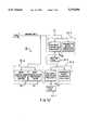
- FIG. 2is a block diagram depicting the major elements of the copier shown in FIG. 1;
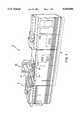
- FIG. 3is a plan view illustrating the principal mechanical elements of the copier shown in FIG. 1;
- FIG. 4is a schematic view illustrating details of a document scanner shown in FIG. 1;
- FIGS. 5A-5Cshow schematic block diagrams of the major parts of the control section for the copier in FIG. 1;
- FIG. 6is a flow chart of calibration steps according to a preferred embodiment of the invention.
- FIGS. 1 and 2there is shown an exemplary laser-based one color (black) printing system 2 for processing print jobs in accordance with the teachings of the invention.
- Printing system 2for purposes of explanation, is divided into a scanner section 6, controller section 7, and printer section 8. While a particular printing system is shown and described, the invention may be used with other types of printing systems that can provide digital capability.
- scanner section 6incorporates a transparent document platen 20 on which a document 22 to be scanned is located.
- One, or more linear arrays 24are supported for reciprocating scanning movement below platen 20.
- Lens 26 and mirrors 28-30cooperate with light source 26A, shadow masks 27A and 28A, and reflector 29A to focus array 24 on a line segment of platen 20 and the document thereon being scanned.
- Array 24through automatic gain control provides image signals or pixels representative of the image scanned that, after suitable processing, are output to controller section 7.
- Processor 25converts the analog image signals output by array 24 to digital and processes the image signals as required to enable system 2 to store and handle the image data in a required form. Processor 25 can also provide enhancements and changes to the image signals such as filtering, thresholding, screening, cropping, or reduction/enlargement.
- Documents to be scannedmay be located on platen 20 by automatic document handler (ADF) 35 operable in either a recirculating document handling (RDH) mode or a semi-automatic document handling (SADH) mode.
- a manual modeis also provided.
- document handler 35has a document tray 37 having documents 22 arranged in stacks or batches.
- the documents 22are advanced by vacuum feed belt 40, document feed rolls 41 and document feed belt 42 onto platen 20 where the document is scanned by array 24. Following scanning, the document is removed from platen 20 by belt 42 and returned to tray 37 by document feed rolls 44.
- a document entry slot 46For operation in a SADH mode, a document entry slot 46 provides access to the document feed belt 42 between tray 37 and platen 20 through which individual documents 22 may be inserted manually for transport to platen 20. Feed rolls 49 behind slot 46 form a nip for engaging and feeding tile document to feed belt 42 and onto platen 20. Following scanning, the document 22 is removed from platen 20 and discharged into catch tray 48.
- printer section 8comprises a laser-type printer and, for purposes of explanation, is divided into a Raster Output Scanner (ROS) section 87, print module section 95, paper supply section 107, and finisher 120.
- ROS 87has a laser 90, the beam of which is split into two imaging beams 94. Each beam is modulated in accordance with the content of an image signal input by acousto-optic modulator 92 to provide dual imaging beams 94.
- Beams 94are scanned across a moving photoreceptor 98 of print module 95 by mirrored facets of a rotating polygon 100 to expose two image lines on photoreceptor 98 with each scan to create latent electrostatic images representing the image signal input.
- Photoreceptor 98is uniformly charged by corotrons 102 at a charging station prior to exposure by imaging beams 94.
- the latent electrostatic imagesare developed by a developer 104 and transferred at transfer station 106 to a print media 108 such as paper by a paper supply section 107.
- Media 108can be of any size, shape or color.
- the print media 108is brought forward in timed registration with the developed image on photoreceptor 98 from either a paper tray 10 or from auxiliary paper trays 112 or 114.
- the developed image transferred to the print media 1(:)8is permanently fused by fuser 116 and the resulting hard copy print is discharged to either output tray 118 or finisher 120.
- Finisher 120includes a stitcher 122 for stitching or stapling the prints together to form books and a thermal binder 124 for adhesively binding the prints into books.
- controller section 7is divided into an image input controller 50, User Interface (UI) 52, system controller 54, main memory 56, image manipulation section 58, and image output controller 60.
- UIUser Interface
- Control section 7includes a plurality of Printed Wiring Boards (PWB's) 70 coupled with one another and with system memory 61 by a pair of memory buses 72, 74.
- Memory controller 76couples system memory 61 with buses 72., 74.
- PWB's 70include system processor 70-1 having plural processors 78; low speed I/0 processor PWB 70-2 having UI communication controller 80 for transmitting date to and from UI 52; PWB's 70-3, 70-4 and 70-5 having disk drive controller/processors 82 for transmitting data to and from disks 90-1, 90-2 and 90-3, respectively, of main memory 56; image manipulation PWB 70-6 with image manipulation processors of image manipulation section 58; image generation processor PWB's 70-7 and 70-8 with image generation processor 86 for processing the image data for printing by printer section 8; dispatch processor 70-9 having dispatch processors 88 and 89 for controlling transmission of data to and from printer section 8; and boot control arbitration scheduler PWB 70-10 which includes memory bus 79, boot
- the scanned image data from processor 25 of scanner section 6 to controller 7is compressed by image compressor 51 of image controller 50 on PWB 70-3. As the image passes through compressor 51, it is segmented into slices N scan lines wide, each slice having a slice pointer.
- the image fileis temporarily stored in system memory 61 at a specific memory location.
- the temporary memorymay be a RAM pending transfer to main memory 56 where the data is held prior to use.
- Main memory 56has plural hard disks 90-1, 90-2, and 90-3 for storing machine operating system software, machine operating data, and the scanned image data currently being processed. It can also store numerous files having data relating to known diagnostic test images at various locations within memory 56.
- UI 52includes a combined operator controller/CRT display consisting of an interactive touchscreen 62, keyboard 64, and mouse 66.
- UI 52interfaces the operator with printing system 2, enabling the operator to program print jobs and other instructions, to obtain system operating information, programming information, diagnostic information, and calibration information.
- Items displayed on touchscreen 62such as files and icons are actuated by either touching the displayed item on screen 62 with a finger or by using mouse 66 to point a cursor 67 to the item selected and keying the mouse.
- main memory 56When the compressed image data in main memory 56 requires further processing, or is required for display on UI 52, or required by printer section 8, the data is accessed in main memory 56. Further processing may also be accomplished by transferring the data to image manipulation section 58 where processing steps such as collation or decomposition are carried out. Following processing, the data may be returned to main memory 56, sent to UI 52, or sent to image output controller 60.
- Image data output to image output controller 60is decompressed and ready for printing by ROS 87 of printer section 8.
- Image data sent for printingis usually purged from memory 56 to make room for new data.
- The, described digital copierincorporates an automatic correction and calibration routine that can be initiated on demand by the operator through UI 52 or can be automatically initiated by the digital copier upon detection of a discrepancy error above a predetermined threshold.
- the routinecan be initiated after a predetermined amount of use or with the passage of a predetermined time period, such as monthly or biweekly depending on machine usage.
- Scanner problemscan be isolated by comparing the scanned image of a known calibration original to expected values. Once corrections are made to the scanner, the input to output of the scanner should be the same or to a known transfer function. Thus, errors in the scanner are now corrected and will not propagate error to other parts of the system.
- the printer portioncan be set up in a similar manner. The copier prints a copy of a known original. The copy is scanned and compared with the expected image. Now the printer is corrected to correct the I/O transfer function.
- printer sectionis correct, other variables can be checked and calibrated.
- geometric setupssuch as image to paper alignment, deletion setups, reduction and magnification corrections can be made using edge detection comparisons instead of level comparisons.
- the routinefirst tests and calibrates a scanning subsystem 6 of the copier. This is accomplished by placing a known test original on document platen 20 and scanning the known original using the scanning subsystem 6. Upon scanning, a scanned digital representation of the scanned known original is stored in memory 56 at a predetermined location within the digital copier. Another memory location, such as in main memory 56 within the digital copier, has stored an actual digital representation of the known original.
- the actual electronic representation storedmay have been electronically generated by the digital copier or any other machine and stored within the digital copier.
- the known test original hard copymay have been printed using a calibrated printer subsection of a copier or any other machine that is completely calibrated to provide a hard copy that completely matches the electronic representation. This enables expected values that are accurately represented.
- the hard copy originalis a known original that has predetermined values for testing purposes and the digital copier has an electronic representation stored in memory that precisely corresponds to the predetermined values of the hard copy for comparison purposes.
- a comparator section 124 within processing subsystem 7 of the digital copiercompares any desired parameters of the scanned digital representation with the actual digital representation. Any differences can be compensated for and calibrated to obtain a desired input/output transfer function for the scanner subsystem 6. Any of a number of parameters such as image density (either B&W or color), linearity, background and image registration, margin adjustments or magnification can be compared. These adjustments can be performed automatically by the system or the system can notify the operator or repair technician, such as through UI 52, as to which subsystem is at fault and the parameter that is out of adjustment, as well as any information relating to the amount of correction or adjustment needed.
- the printer subsystem 8is next calibrated by printing a hard copy of a known test image. This can be performed using a test signal generator that sends a known digital representation of an image to the printer subsystem 8 or can use the actual digital representation of the known original used in the scanning subsystem testing and already stored in memory, having expected test values.
- the hard copyis printed, it is aligned on document platen 20 and scanned using the previously calibrated scanning subsystem 6.
- the aligning of the hard copy on document platen 20can be performed manually and aligned with various alignment marks on platen 20. Preferably, this is performed manually to isolate any document transport misalignment from affecting calibration of printer subsystem 8.
- the scanned digital representation of the imageis compared with the previously stored actual digital representation. Electronic comparison of parameters of the scanned and actual representation takes place using comparator 124 and if any differences are determined, the printer subsystem's input/output transfer function is calibrated to a desired value. This is possible because the copier can calculate the difference between the input and output of the system at various points forming a standard closed loop control system. Any adjustments needed may be automatically calibrated by the system or alerted to an operator or repair technician through UI 52.
- an automatic document transporting subsystemcan be tested by placing a known original or the previously produced hard copy on input tray 37 within the copier for receiving originals. This can be transported to document platen 20 by the transport subsystem and scanned by the previously calibrated scanner subsystem 6. Previously stored digital representations of the original can be compared with the scanned representation and timing or registration of the transport subsystem can be adjusted or calibrated to a desired input/output transfer function.
- the calibration step for each subsystemmay be iterative. This may be desirable if many variables within the subsystem require adjustment, if large misalignments are determined, or if a feedback loop is desired to ensure that the transfer function is appropriate.
- a multi-colored documentis scanned and converted to digital signals corresponding to the respective densities of red, green and blue (RGB). These signals are converted to a CIE space and stored. Prior to printing, the signals are manipulated to cyan, yellow, magenta and/or black (CYMK) and printed one color at a time by separate developer stations.
- RGBred, green and blue
- CYMKmagenta and/or black
- the inventive copy quality correction and calibration routineis even more necessary to maintain good image quality. Besides the color adjustments, there may also be errors in image misregistration of one or more colors relative to the other colors. This can distort and decrease the quality of the image. There also is the manipulations of one color space to, another (RGB to CYM(K)) that may be additional sources of miscalibration.
- the inventive apparatus and methodworks substantially the same as in the one color (black) example.
- the scanning subsystemis calibrated by placing a known original on the document platen and scanning the known original using the scanning subsystem. Because full color is being calibrated, the known original may contain a test image with portions of at least the basic colors Red, Green and Blue, a test image with more than the basic colors, or separate test images each having a different color.
- the testing processwould be iterative. A single color would be scanned, compared and calibrated as previously discussed. Then a subsequent test image of a different color would be scanned, compared and calibrated. This would continue until all desired colors have been calibrated in the scanner subsystem. Any desired parameters can be compared and calibrated. For example, color intensity level, alignment, saturation, hue, contrast, magnification or skew.
- the printer subsystemis calibrated. This is performed by printing a hard copy of a known test image that is stored in memory (RAM in the case of the preferred exemplary color copier).
- the test imagemay be of full color, or multiple test images, each of a different color, may be provided to calibrate the printer subsystem. In the latter, an iterative printing, scanning, comparison, and calibration process takes place to calibrate the printer subsystem for all colors CYM(K).
- the hard copy(or copies) is produced, it is aligned on the document platen and scanned using the previously calibrated scanner subsystem.
- the scanned digital representation of the imageis compared with the known test image values already stored in memory. Any differences are determined, and the printer subsystem's I/O transfer function is calibrated to a desired output.
- Calibration parameterscan include the same as in the scanner calibration and can additionally calibrate misregistrations of a particular color caused by document transport errors that may occur. This is more likely to occur in a full color copy because the image is not formed as a single image, but rather is formed by successive latent images superimposed in registration.
Landscapes
- Engineering & Computer Science (AREA)
- Multimedia (AREA)
- Signal Processing (AREA)
- Health & Medical Sciences (AREA)
- Biomedical Technology (AREA)
- General Health & Medical Sciences (AREA)
- Microelectronics & Electronic Packaging (AREA)
- Physics & Mathematics (AREA)
- General Physics & Mathematics (AREA)
- Facsimiles In General (AREA)
- Control Or Security For Electrophotography (AREA)
- Facsimile Scanning Arrangements (AREA)
Abstract
Description
Claims (19)
Priority Applications (3)
| Application Number | Priority Date | Filing Date | Title |
|---|---|---|---|
| US08/077,904US5510896A (en) | 1993-06-18 | 1993-06-18 | Automatic copy quality correction and calibration |
| CA002121620ACA2121620C (en) | 1993-06-18 | 1994-04-19 | Automatic copy quality correction and calibration |
| JP6128448AJPH0738687A (en) | 1993-06-18 | 1994-06-10 | Digital copying machine |
Applications Claiming Priority (1)
| Application Number | Priority Date | Filing Date | Title |
|---|---|---|---|
| US08/077,904US5510896A (en) | 1993-06-18 | 1993-06-18 | Automatic copy quality correction and calibration |
Publications (1)
| Publication Number | Publication Date |
|---|---|
| US5510896Atrue US5510896A (en) | 1996-04-23 |
Family
ID=22140707
Family Applications (1)
| Application Number | Title | Priority Date | Filing Date |
|---|---|---|---|
| US08/077,904Expired - LifetimeUS5510896A (en) | 1993-06-18 | 1993-06-18 | Automatic copy quality correction and calibration |
Country Status (3)
| Country | Link |
|---|---|
| US (1) | US5510896A (en) |
| JP (1) | JPH0738687A (en) |
| CA (1) | CA2121620C (en) |
Cited By (72)
| Publication number | Priority date | Publication date | Assignee | Title |
|---|---|---|---|---|
| US5642202A (en)* | 1994-12-01 | 1997-06-24 | Xerox Corporation | Scan image target locator system for calibrating a printing system |
| US5682573A (en)* | 1995-03-01 | 1997-10-28 | Fuji Xerox Co., Ltd. | Image quality control in image forming apparatus |
| US5721623A (en)* | 1994-05-06 | 1998-02-24 | U.S. Philips Corporation | Method and device for adjusting a hard-copy-unit |
| US5724450A (en)* | 1994-09-30 | 1998-03-03 | Apple Computer, Inc. | Method and system for color image compression in conjunction with color transformation techniques |
| WO1998009427A1 (en)* | 1996-08-28 | 1998-03-05 | Ralip International Ab | Method and arrangement for ensuring quality during scanning/copying of images/documents |
| US5734407A (en)* | 1995-03-31 | 1998-03-31 | Fuji Xerox Co., Ltd. | Image quality control at restart of image forming apparatus |
| US5844687A (en)* | 1994-12-28 | 1998-12-01 | Canon Kabushiki Kaisha | Image processing apparatus |
| US5884118A (en)* | 1996-11-26 | 1999-03-16 | Xerox Corporation | Printer having print output linked to scanner input for automated image quality adjustment |
| US6036297A (en)* | 1994-10-28 | 2000-03-14 | Canon Kabushiki Kaisha | Method and apparatus for correcting printhead, printhead correction by this apparatus, and printer using this printhead |
| US6042213A (en)* | 1994-10-28 | 2000-03-28 | Canon Kabushiki Kaisha | Method and apparatus for correcting printhead, printhead corrected by this apparatus, and printing apparatus using this printhead |
| US6069707A (en)* | 1996-09-20 | 2000-05-30 | Pekelman; Gil | System for reproducing a physical color image |
| US6157790A (en)* | 1997-10-22 | 2000-12-05 | Minolta Co., Ltd. | Image formation parameter correction apparatus |
| US6226419B1 (en) | 1999-02-26 | 2001-05-01 | Electronics For Imaging, Inc. | Automatic margin alignment using a digital document processor |
| US20010006425A1 (en)* | 1999-12-28 | 2001-07-05 | Tetsuya Takamori | Image processing condition setting apparatus and image processing condition setting program storage medium |
| US6307981B1 (en)* | 1996-12-06 | 2001-10-23 | Minolta Co., Ltd. | Image forming device |
| EP1158778A1 (en)* | 2000-05-26 | 2001-11-28 | AGFA-GEVAERT naamloze vennootschap | Calibration method for digital camera and printer. |
| US6384941B1 (en)* | 1997-11-04 | 2002-05-07 | Samsung Electronics Co., Ltd. | Apparatus for image correction of multifunctional peripherals and method therefor |
| US20020063907A1 (en)* | 2000-11-29 | 2002-05-30 | Harrington Steven J. | Color calibration alarm apparatus and method for use in an image-rendering device |
| US6418281B1 (en)* | 1999-02-24 | 2002-07-09 | Canon Kabushiki Kaisha | Image processing apparatus having calibration for image exposure output |
| US6519552B1 (en) | 1999-09-15 | 2003-02-11 | Xerox Corporation | Systems and methods for a hybrid diagnostic approach of real time diagnosis of electronic systems |
| US6522430B1 (en) | 1999-11-29 | 2003-02-18 | Xerox Corporation | Quantification of motion quality effect on image quality |
| US6529616B1 (en) | 1999-11-29 | 2003-03-04 | Xerox Corporation | Technique for accurate color-color registration measurements |
| US6571000B1 (en) | 1999-11-29 | 2003-05-27 | Xerox Corporation | Image processing algorithm for characterization of uniformity of printed images |
| EP1320251A1 (en)* | 2001-11-28 | 2003-06-18 | Xerox Corporation | Semi-automatic image registration control for a digital copier |
| US6597473B1 (en)* | 1999-11-29 | 2003-07-22 | Xerox Corporation | Method to obtain consistent image quality measurements from different image input devices |
| US6606395B1 (en) | 1999-11-29 | 2003-08-12 | Xerox Corporation | Method to allow automated image quality analysis of arbitrary test patterns |
| US6608932B1 (en) | 1999-11-29 | 2003-08-19 | Xerox Corporation | Outline font for analytical assessment of printed text quality |
| US6643035B1 (en)* | 1999-11-24 | 2003-11-04 | Xerox Corporation | Method and apparatus for measuring scanner registration |
| US6665425B1 (en) | 1999-12-16 | 2003-12-16 | Xerox Corporation | Systems and methods for automated image quality based diagnostics and remediation of document processing systems |
| EP1427176A1 (en)* | 2002-11-28 | 2004-06-09 | Océ-Technologies B.V. | A method and apparatus for calibrating a transport scanner and a test original for use with such method and apparatus |
| US6753987B1 (en) | 2000-02-25 | 2004-06-22 | Xerox Corporation | Systems and methods to determine a contrast and a brightness adjusted system tone reproduction curve |
| US20040150861A1 (en)* | 2002-11-28 | 2004-08-05 | Van Der Heijden Gerardus J.E.L. | Method and apparatus for calibrating a transport scanner and a test original for use with such method |
| US20040174404A1 (en)* | 2003-03-04 | 2004-09-09 | Canon Kabushiki Kaisha | Image forming apparatus, image processing apparatus, and control methods therefor |
| US20040190019A1 (en)* | 2003-03-28 | 2004-09-30 | Hong Li | Methods, systems, and media to enhance image processing in a color reprographic system |
| US6813573B2 (en)* | 2001-05-03 | 2004-11-02 | Hewlett-Packard Development Company, L.P. | Apparatus and method for calibration of scan position for a peripheral device with document feeder |
| US20040223648A1 (en)* | 2003-05-05 | 2004-11-11 | Keith Hoene | Determining differences between documents |
| US6842266B1 (en) | 2000-02-25 | 2005-01-11 | Xerox Corporation | Systems and methods that determine an image processing system tone reproduction curve |
| US6892317B1 (en) | 1999-12-16 | 2005-05-10 | Xerox Corporation | Systems and methods for failure prediction, diagnosis and remediation using data acquisition and feedback for a distributed electronic system |
| US6912071B1 (en) | 1999-11-29 | 2005-06-28 | Xerox Corporation | Virtual tech rep by remote image quality analysis |
| US20050259276A1 (en)* | 2002-03-29 | 2005-11-24 | Smith James T Ii | Methods, systems, and media to calibrate a reprographic system |
| US20050264832A1 (en)* | 1999-08-31 | 2005-12-01 | Baum Daniel R | Printing images in an optimized manner |
| US20050270325A1 (en)* | 2004-06-07 | 2005-12-08 | Cavill Barry R | System and method for calibrating ink ejecting nozzles in a printer/scanner |
| US20060110009A1 (en)* | 2004-11-22 | 2006-05-25 | Xerox Corporation | Systems and methods for detecting image quality defects |
| US20060115284A1 (en)* | 2004-11-30 | 2006-06-01 | Xerox Corporation. | Semi-automatic image quality adjustment for multiple marking engine systems |
| US20060215240A1 (en)* | 2005-03-25 | 2006-09-28 | Xerox Corporation | Image quality control method and apparatus for multiple marking engine systems |
| WO2006105667A1 (en)* | 2005-04-06 | 2006-10-12 | Kodak Graphic Communications Canada Company | Methods and apparatus for correcting banding of imaged regular patterns |
| US20060274334A1 (en)* | 2005-06-07 | 2006-12-07 | Xerox Corporation | Low cost adjustment method for printing systems |
| US7149001B1 (en) | 1999-11-19 | 2006-12-12 | Sharp Laboratories Of America, Inc. | System for supporting a multiplicity of copy features |
| US20060279790A1 (en)* | 2005-06-10 | 2006-12-14 | Fuji Xerox Co., Ltd. | Image processing system |
| US20070030537A1 (en)* | 2001-07-10 | 2007-02-08 | Che-Kuei Mai | Back-light module for image scanning device and method for calibrating illumination with the back-light module |
| JP2007143109A (en)* | 2005-10-17 | 2007-06-07 | Riso Kagaku Corp | Image reading apparatus and printing system |
| US20070264037A1 (en)* | 2006-05-12 | 2007-11-15 | Xerox Corporation | Process controls methods and apparatuses for improved image consistency |
| US20070263238A1 (en)* | 2006-05-12 | 2007-11-15 | Xerox Corporation | Automatic image quality control of marking processes |
| US20080158606A1 (en)* | 2006-12-28 | 2008-07-03 | Fuji Xerox Co., Ltd. | Image forming apparatus, image processing apparatus, image processing method, computer data signal, and computer readable medium |
| US20080192275A1 (en)* | 2003-09-30 | 2008-08-14 | Reed Alastair M | Methods and Apparatuses for Printer Calibration |
| US20080219513A1 (en)* | 2007-03-06 | 2008-09-11 | Samsung Electronics Co., Ltd | Print quality evaluation apparatus and method of print quality evaluation |
| US20080278437A1 (en)* | 2007-03-13 | 2008-11-13 | Barrus John W | Copying documents from electronic displays |
| US20090041370A1 (en)* | 2007-08-09 | 2009-02-12 | Xerox Corporation | Background noise detection on rendered documents |
| GB2407932B (en)* | 2003-11-05 | 2009-06-24 | Canon Europa Nv | Automatic generation and use of colour profiles for scanners |
| US20090161128A1 (en)* | 2007-12-21 | 2009-06-25 | Xerox Corporation | Color image process controls methods and systems |
| US20090185235A1 (en)* | 2008-01-17 | 2009-07-23 | Fuji Xerox Co., Ltd. | Image processing apparatus, image processing method, recording medium storing image processing program, and computer data signal embedded in carrier wave |
| US20090190838A1 (en)* | 2008-01-29 | 2009-07-30 | K-Nfb, Inc. Reading Technology, Inc. | Training a User on an Accessiblity Device |
| US20090296111A1 (en)* | 2008-05-27 | 2009-12-03 | Xerox Corporation | Methods, systems and apparatus to control hue variation for multiple marking engine printing systems |
| US20090316207A1 (en)* | 1998-03-27 | 2009-12-24 | Canon Kabushiki Kaisha | Image processing apparatus, control method of image processing apparatus, and storage medium storing therein control program for image processing apparatus |
| US20100047000A1 (en)* | 2008-08-22 | 2010-02-25 | Xerox Corporation | Automated method and system for self-calibration of image on media sheets using an auto duplex media path |
| EP2574030A1 (en)* | 2011-09-23 | 2013-03-27 | Cal-Comp Electronics & Communications Company Ltd. | Product performance test system for scanner with automatic document feeder and method thereof |
| US8547563B2 (en) | 2010-11-04 | 2013-10-01 | Xerox Corporation | Mobile device scan for printing devices |
| US8824029B2 (en) | 2011-06-16 | 2014-09-02 | Cal-Comp Electronics & Communications Company Limited | Color calibration method and image processing device using the same |
| US20140355042A1 (en)* | 2013-05-31 | 2014-12-04 | Hewlett-Packard Development Company, L.P. | Printing System |
| US10274883B1 (en) | 2018-02-02 | 2019-04-30 | Eastman Kodak Company | Characterizing cross-track spacing variations in electrophotographic printer |
| US11131951B2 (en) | 2018-03-28 | 2021-09-28 | Hewlett-Packard Development Company, L.P. | Controlling voltage profiles |
| US20250036061A1 (en)* | 2020-03-19 | 2025-01-30 | Canon Kabushiki Kaisha | Image forming apparatus |
Families Citing this family (2)
| Publication number | Priority date | Publication date | Assignee | Title |
|---|---|---|---|---|
| EP0735738B1 (en)* | 1995-03-30 | 2006-07-26 | Hewlett-Packard Company, A Delaware Corporation | Facsimile scan position calibration apparatus and method |
| JP6521664B2 (en)* | 2015-02-20 | 2019-05-29 | キヤノン株式会社 | Image formation system |
Citations (20)
| Publication number | Priority date | Publication date | Assignee | Title |
|---|---|---|---|---|
| US4335952A (en)* | 1980-09-11 | 1982-06-22 | International Business Machines Corporation | Copy quality diagnostic procedure |
| US4627721A (en)* | 1985-11-20 | 1986-12-09 | Xerox Corporation | Automatic scanning optics alignment |
| US4710785A (en)* | 1986-12-12 | 1987-12-01 | Eastman Kodak Company | Process control for electrostatographic machine |
| US4733276A (en)* | 1986-02-18 | 1988-03-22 | Ricoh Company, Ltd. | Automatic density control device for use in copying machine |
| US4779106A (en)* | 1986-12-12 | 1988-10-18 | Eastman Kodak Company | Process control for electrostatographic machine |
| US4831420A (en)* | 1988-01-19 | 1989-05-16 | Xerox Corporation | Copier/document handler customer variable registration system |
| US4970557A (en)* | 1987-09-02 | 1990-11-13 | Sharp Kabushiki Kaisha | Electrophotographic apparatus controlling image quality according to condition of deterioration |
| US4972257A (en)* | 1989-04-03 | 1990-11-20 | Xerox Corporation | Operator adjustable color image processing |
| US4999673A (en)* | 1989-05-10 | 1991-03-12 | Xerox Corporation | Process control by creating and sensing half-tone test patches |
| US5016050A (en)* | 1989-04-27 | 1991-05-14 | Xerox Corporation | Xerographic setup and operating system for electrostatographic reproduction machines |
| US5030989A (en)* | 1989-01-14 | 1991-07-09 | Mita Industrial Co., Ltd. | Distortion checking device in an electrophotographic copying apparatus |
| US5107299A (en)* | 1990-09-28 | 1992-04-21 | Xerox Corporation | Printer job recovery of complete or partially complete jobs in an electronic reprographic printing system |
| US5138377A (en)* | 1991-05-23 | 1992-08-11 | Xerox Corporation | Internal expert system to aid in servicing |
| US5148286A (en)* | 1990-09-28 | 1992-09-15 | Xerox Corporation | Method and apparatus for operating an electronic reprographic printing system upon scan interruption |
| US5153745A (en)* | 1990-09-28 | 1992-10-06 | Xerox Corporation | Method and apparatus for compensating for illumination variations of a lamp in a document scanning system following extended lamp inactivity |
| US5161010A (en)* | 1990-10-11 | 1992-11-03 | Xerox Corporation | Color image processing apparatus for substituting a black pigment for improved black copying |
| US5200958A (en)* | 1990-09-28 | 1993-04-06 | Xerox Corporation | Method and apparatus for recording and diagnosing faults in an electronic reprographic printing system |
| US5255085A (en)* | 1991-10-25 | 1993-10-19 | Eastman Kodak Company | Adaptive technique for providing accurate tone reproduction control in an imaging system |
| US5339176A (en)* | 1990-02-05 | 1994-08-16 | Scitex Corporation Ltd. | Apparatus and method for color calibration |
| US5345315A (en)* | 1988-11-23 | 1994-09-06 | Imatec, Ltd. | Method and system for improved tone and color reproduction of electronic image on hard copy using a closed loop control |
- 1993
- 1993-06-18USUS08/077,904patent/US5510896A/ennot_activeExpired - Lifetime
- 1994
- 1994-04-19CACA002121620Apatent/CA2121620C/ennot_activeExpired - Lifetime
- 1994-06-10JPJP6128448Apatent/JPH0738687A/enactivePending
Patent Citations (20)
| Publication number | Priority date | Publication date | Assignee | Title |
|---|---|---|---|---|
| US4335952A (en)* | 1980-09-11 | 1982-06-22 | International Business Machines Corporation | Copy quality diagnostic procedure |
| US4627721A (en)* | 1985-11-20 | 1986-12-09 | Xerox Corporation | Automatic scanning optics alignment |
| US4733276A (en)* | 1986-02-18 | 1988-03-22 | Ricoh Company, Ltd. | Automatic density control device for use in copying machine |
| US4710785A (en)* | 1986-12-12 | 1987-12-01 | Eastman Kodak Company | Process control for electrostatographic machine |
| US4779106A (en)* | 1986-12-12 | 1988-10-18 | Eastman Kodak Company | Process control for electrostatographic machine |
| US4970557A (en)* | 1987-09-02 | 1990-11-13 | Sharp Kabushiki Kaisha | Electrophotographic apparatus controlling image quality according to condition of deterioration |
| US4831420A (en)* | 1988-01-19 | 1989-05-16 | Xerox Corporation | Copier/document handler customer variable registration system |
| US5345315A (en)* | 1988-11-23 | 1994-09-06 | Imatec, Ltd. | Method and system for improved tone and color reproduction of electronic image on hard copy using a closed loop control |
| US5030989A (en)* | 1989-01-14 | 1991-07-09 | Mita Industrial Co., Ltd. | Distortion checking device in an electrophotographic copying apparatus |
| US4972257A (en)* | 1989-04-03 | 1990-11-20 | Xerox Corporation | Operator adjustable color image processing |
| US5016050A (en)* | 1989-04-27 | 1991-05-14 | Xerox Corporation | Xerographic setup and operating system for electrostatographic reproduction machines |
| US4999673A (en)* | 1989-05-10 | 1991-03-12 | Xerox Corporation | Process control by creating and sensing half-tone test patches |
| US5339176A (en)* | 1990-02-05 | 1994-08-16 | Scitex Corporation Ltd. | Apparatus and method for color calibration |
| US5107299A (en)* | 1990-09-28 | 1992-04-21 | Xerox Corporation | Printer job recovery of complete or partially complete jobs in an electronic reprographic printing system |
| US5148286A (en)* | 1990-09-28 | 1992-09-15 | Xerox Corporation | Method and apparatus for operating an electronic reprographic printing system upon scan interruption |
| US5153745A (en)* | 1990-09-28 | 1992-10-06 | Xerox Corporation | Method and apparatus for compensating for illumination variations of a lamp in a document scanning system following extended lamp inactivity |
| US5200958A (en)* | 1990-09-28 | 1993-04-06 | Xerox Corporation | Method and apparatus for recording and diagnosing faults in an electronic reprographic printing system |
| US5161010A (en)* | 1990-10-11 | 1992-11-03 | Xerox Corporation | Color image processing apparatus for substituting a black pigment for improved black copying |
| US5138377A (en)* | 1991-05-23 | 1992-08-11 | Xerox Corporation | Internal expert system to aid in servicing |
| US5255085A (en)* | 1991-10-25 | 1993-10-19 | Eastman Kodak Company | Adaptive technique for providing accurate tone reproduction control in an imaging system |
Cited By (111)
| Publication number | Priority date | Publication date | Assignee | Title |
|---|---|---|---|---|
| US5721623A (en)* | 1994-05-06 | 1998-02-24 | U.S. Philips Corporation | Method and device for adjusting a hard-copy-unit |
| US5724450A (en)* | 1994-09-30 | 1998-03-03 | Apple Computer, Inc. | Method and system for color image compression in conjunction with color transformation techniques |
| US6036297A (en)* | 1994-10-28 | 2000-03-14 | Canon Kabushiki Kaisha | Method and apparatus for correcting printhead, printhead correction by this apparatus, and printer using this printhead |
| US6042213A (en)* | 1994-10-28 | 2000-03-28 | Canon Kabushiki Kaisha | Method and apparatus for correcting printhead, printhead corrected by this apparatus, and printing apparatus using this printhead |
| US5642202A (en)* | 1994-12-01 | 1997-06-24 | Xerox Corporation | Scan image target locator system for calibrating a printing system |
| US5844687A (en)* | 1994-12-28 | 1998-12-01 | Canon Kabushiki Kaisha | Image processing apparatus |
| US5682573A (en)* | 1995-03-01 | 1997-10-28 | Fuji Xerox Co., Ltd. | Image quality control in image forming apparatus |
| US5734407A (en)* | 1995-03-31 | 1998-03-31 | Fuji Xerox Co., Ltd. | Image quality control at restart of image forming apparatus |
| WO1998009427A1 (en)* | 1996-08-28 | 1998-03-05 | Ralip International Ab | Method and arrangement for ensuring quality during scanning/copying of images/documents |
| US6345130B1 (en) | 1996-08-28 | 2002-02-05 | Ralip International Ab | Method and arrangement for ensuring quality during scanning/copying of images/documents |
| US6069707A (en)* | 1996-09-20 | 2000-05-30 | Pekelman; Gil | System for reproducing a physical color image |
| US5884118A (en)* | 1996-11-26 | 1999-03-16 | Xerox Corporation | Printer having print output linked to scanner input for automated image quality adjustment |
| EP0844785A3 (en)* | 1996-11-26 | 2000-01-19 | Xerox Corporation | Linking print output to scanner input for automated image quality adjustment |
| US6307981B1 (en)* | 1996-12-06 | 2001-10-23 | Minolta Co., Ltd. | Image forming device |
| US6157790A (en)* | 1997-10-22 | 2000-12-05 | Minolta Co., Ltd. | Image formation parameter correction apparatus |
| US6384941B1 (en)* | 1997-11-04 | 2002-05-07 | Samsung Electronics Co., Ltd. | Apparatus for image correction of multifunctional peripherals and method therefor |
| US20090316207A1 (en)* | 1998-03-27 | 2009-12-24 | Canon Kabushiki Kaisha | Image processing apparatus, control method of image processing apparatus, and storage medium storing therein control program for image processing apparatus |
| US8300253B2 (en) | 1998-03-27 | 2012-10-30 | Canon Kabushika Kaisha | Image forming apparatus, method of controlling image forming apparatus, and memory medium for storing computer program for executing method, with interpreter for control programs that are provided for execution on OS-independent platform |
| EP2134072B1 (en)* | 1998-03-27 | 2013-06-19 | Canon Kabushiki Kaisha | Image processing apparatus, control method of image processing apparatus, and storage medium storing therein control program for image processing apparatus |
| EP2276231B1 (en)* | 1998-03-27 | 2013-11-13 | Canon Kabushiki Kaisha | Image processing apparatus, control method of image processing apparatus, and storage medium storing therein control program for image processing apparatus |
| US6418281B1 (en)* | 1999-02-24 | 2002-07-09 | Canon Kabushiki Kaisha | Image processing apparatus having calibration for image exposure output |
| US6226419B1 (en) | 1999-02-26 | 2001-05-01 | Electronics For Imaging, Inc. | Automatic margin alignment using a digital document processor |
| US20050264832A1 (en)* | 1999-08-31 | 2005-12-01 | Baum Daniel R | Printing images in an optimized manner |
| US6519552B1 (en) | 1999-09-15 | 2003-02-11 | Xerox Corporation | Systems and methods for a hybrid diagnostic approach of real time diagnosis of electronic systems |
| US7149001B1 (en) | 1999-11-19 | 2006-12-12 | Sharp Laboratories Of America, Inc. | System for supporting a multiplicity of copy features |
| US6643035B1 (en)* | 1999-11-24 | 2003-11-04 | Xerox Corporation | Method and apparatus for measuring scanner registration |
| US6597473B1 (en)* | 1999-11-29 | 2003-07-22 | Xerox Corporation | Method to obtain consistent image quality measurements from different image input devices |
| US6606395B1 (en) | 1999-11-29 | 2003-08-12 | Xerox Corporation | Method to allow automated image quality analysis of arbitrary test patterns |
| US6608932B1 (en) | 1999-11-29 | 2003-08-19 | Xerox Corporation | Outline font for analytical assessment of printed text quality |
| US6522430B1 (en) | 1999-11-29 | 2003-02-18 | Xerox Corporation | Quantification of motion quality effect on image quality |
| US6529616B1 (en) | 1999-11-29 | 2003-03-04 | Xerox Corporation | Technique for accurate color-color registration measurements |
| US6571000B1 (en) | 1999-11-29 | 2003-05-27 | Xerox Corporation | Image processing algorithm for characterization of uniformity of printed images |
| US6912071B1 (en) | 1999-11-29 | 2005-06-28 | Xerox Corporation | Virtual tech rep by remote image quality analysis |
| US6665425B1 (en) | 1999-12-16 | 2003-12-16 | Xerox Corporation | Systems and methods for automated image quality based diagnostics and remediation of document processing systems |
| US6892317B1 (en) | 1999-12-16 | 2005-05-10 | Xerox Corporation | Systems and methods for failure prediction, diagnosis and remediation using data acquisition and feedback for a distributed electronic system |
| US7212311B2 (en)* | 1999-12-28 | 2007-05-01 | Fujifilm Corporation | Image processing condition setting apparatus and image processing condition setting program storage medium |
| US20010006425A1 (en)* | 1999-12-28 | 2001-07-05 | Tetsuya Takamori | Image processing condition setting apparatus and image processing condition setting program storage medium |
| US6842266B1 (en) | 2000-02-25 | 2005-01-11 | Xerox Corporation | Systems and methods that determine an image processing system tone reproduction curve |
| US6753987B1 (en) | 2000-02-25 | 2004-06-22 | Xerox Corporation | Systems and methods to determine a contrast and a brightness adjusted system tone reproduction curve |
| EP1158778A1 (en)* | 2000-05-26 | 2001-11-28 | AGFA-GEVAERT naamloze vennootschap | Calibration method for digital camera and printer. |
| EP1211885A3 (en)* | 2000-11-29 | 2003-03-19 | Xerox Corporation | Color calibration alarm for use in an image-rendering device |
| US7081976B2 (en) | 2000-11-29 | 2006-07-25 | Xerox Corporation | Color calibration alarm apparatus and method for use in an image-rendering device |
| US20020063907A1 (en)* | 2000-11-29 | 2002-05-30 | Harrington Steven J. | Color calibration alarm apparatus and method for use in an image-rendering device |
| US6813573B2 (en)* | 2001-05-03 | 2004-11-02 | Hewlett-Packard Development Company, L.P. | Apparatus and method for calibration of scan position for a peripheral device with document feeder |
| US7525699B2 (en) | 2001-07-10 | 2009-04-28 | Che-Kuei Mai | Back-light module for image scanning device and method for calibrating illumination with back-light module |
| US20070064287A1 (en)* | 2001-07-10 | 2007-03-22 | Che-Kuei Mai | Back-light module for image scanning device and method for calibrating illumination with the back-light module |
| US20070030537A1 (en)* | 2001-07-10 | 2007-02-08 | Che-Kuei Mai | Back-light module for image scanning device and method for calibrating illumination with the back-light module |
| US7106477B2 (en) | 2001-11-28 | 2006-09-12 | Xerox Corporation | Semi-automatic image registration control for a digital copier |
| EP1320251A1 (en)* | 2001-11-28 | 2003-06-18 | Xerox Corporation | Semi-automatic image registration control for a digital copier |
| US20050259276A1 (en)* | 2002-03-29 | 2005-11-24 | Smith James T Ii | Methods, systems, and media to calibrate a reprographic system |
| US7557964B2 (en) | 2002-03-29 | 2009-07-07 | Infoprint Solutions Company, Llc | Methods, systems, and media to calibrate a reprographic system |
| US8238000B2 (en) | 2002-11-28 | 2012-08-07 | Oce-Technologies B.V. | Method and apparatus for calibrating a transport scanner and a test original for use with such method |
| US20040150861A1 (en)* | 2002-11-28 | 2004-08-05 | Van Der Heijden Gerardus J.E.L. | Method and apparatus for calibrating a transport scanner and a test original for use with such method |
| EP1427176A1 (en)* | 2002-11-28 | 2004-06-09 | Océ-Technologies B.V. | A method and apparatus for calibrating a transport scanner and a test original for use with such method and apparatus |
| US20040174404A1 (en)* | 2003-03-04 | 2004-09-09 | Canon Kabushiki Kaisha | Image forming apparatus, image processing apparatus, and control methods therefor |
| US7639392B2 (en)* | 2003-03-28 | 2009-12-29 | Infoprint Solutions Company, Llc | Methods, systems, and media to enhance image processing in a color reprographic system |
| US20040190019A1 (en)* | 2003-03-28 | 2004-09-30 | Hong Li | Methods, systems, and media to enhance image processing in a color reprographic system |
| US20090174902A1 (en)* | 2003-03-28 | 2009-07-09 | Hong Li | Methods, systems, and media to enhance image processing in a color reprographic system |
| US8018624B2 (en)* | 2003-03-28 | 2011-09-13 | Ricoh Production Print Solutions LLC | Methods, systems, and media to enhance image processing in a color reprographic system |
| US20040223648A1 (en)* | 2003-05-05 | 2004-11-11 | Keith Hoene | Determining differences between documents |
| US20090086230A1 (en)* | 2003-09-30 | 2009-04-02 | Reed Alastair M | Methods and Apparatuses for Printer Calibration |
| US8149458B2 (en) | 2003-09-30 | 2012-04-03 | Digimarc Corporation | Methods and apparatuses for printer calibration |
| US20080192275A1 (en)* | 2003-09-30 | 2008-08-14 | Reed Alastair M | Methods and Apparatuses for Printer Calibration |
| US8009324B2 (en) | 2003-09-30 | 2011-08-30 | Digimarc Corporation | Methods and apparatuses for printer calibration |
| GB2407932B (en)* | 2003-11-05 | 2009-06-24 | Canon Europa Nv | Automatic generation and use of colour profiles for scanners |
| US20050270325A1 (en)* | 2004-06-07 | 2005-12-08 | Cavill Barry R | System and method for calibrating ink ejecting nozzles in a printer/scanner |
| US20060110009A1 (en)* | 2004-11-22 | 2006-05-25 | Xerox Corporation | Systems and methods for detecting image quality defects |
| US7376269B2 (en) | 2004-11-22 | 2008-05-20 | Xerox Corporation | Systems and methods for detecting image quality defects |
| US20060115284A1 (en)* | 2004-11-30 | 2006-06-01 | Xerox Corporation. | Semi-automatic image quality adjustment for multiple marking engine systems |
| US7162172B2 (en) | 2004-11-30 | 2007-01-09 | Xerox Corporation | Semi-automatic image quality adjustment for multiple marking engine systems |
| US7697151B2 (en) | 2005-03-25 | 2010-04-13 | Xerox Corporation | Image quality control method and apparatus for multiple marking engine systems |
| US20060215240A1 (en)* | 2005-03-25 | 2006-09-28 | Xerox Corporation | Image quality control method and apparatus for multiple marking engine systems |
| US20090066796A1 (en)* | 2005-04-06 | 2009-03-12 | Kodak Graphic Communications Canada Company | Methods and Apparatus for Correcting Banding of Imaged Regular Patterns |
| WO2006105667A1 (en)* | 2005-04-06 | 2006-10-12 | Kodak Graphic Communications Canada Company | Methods and apparatus for correcting banding of imaged regular patterns |
| US7847940B2 (en) | 2005-04-06 | 2010-12-07 | Eastman Kodak Company | Methods and apparatus for correcting banding of imaged regular patterns |
| US20060274334A1 (en)* | 2005-06-07 | 2006-12-07 | Xerox Corporation | Low cost adjustment method for printing systems |
| US8004729B2 (en)* | 2005-06-07 | 2011-08-23 | Xerox Corporation | Low cost adjustment method for printing systems |
| US20060279790A1 (en)* | 2005-06-10 | 2006-12-14 | Fuji Xerox Co., Ltd. | Image processing system |
| US7626713B2 (en)* | 2005-06-10 | 2009-12-01 | Fuji Xerox Co., Ltd. | Image processing system that reduces image uneveness |
| US20090147298A1 (en)* | 2005-10-17 | 2009-06-11 | Riso Kagaku Corporation | Image reading device and printing system |
| JP2007143109A (en)* | 2005-10-17 | 2007-06-07 | Riso Kagaku Corp | Image reading apparatus and printing system |
| US20070264037A1 (en)* | 2006-05-12 | 2007-11-15 | Xerox Corporation | Process controls methods and apparatuses for improved image consistency |
| US7382993B2 (en) | 2006-05-12 | 2008-06-03 | Xerox Corporation | Process controls methods and apparatuses for improved image consistency |
| US20070263238A1 (en)* | 2006-05-12 | 2007-11-15 | Xerox Corporation | Automatic image quality control of marking processes |
| US7800777B2 (en) | 2006-05-12 | 2010-09-21 | Xerox Corporation | Automatic image quality control of marking processes |
| US20080158606A1 (en)* | 2006-12-28 | 2008-07-03 | Fuji Xerox Co., Ltd. | Image forming apparatus, image processing apparatus, image processing method, computer data signal, and computer readable medium |
| US7916346B2 (en)* | 2006-12-28 | 2011-03-29 | Fuji Xerox Co., Ltd. | Image forming apparatus, image processing apparatus, image processing method, computer data signal, and computer readable medium |
| US20080219513A1 (en)* | 2007-03-06 | 2008-09-11 | Samsung Electronics Co., Ltd | Print quality evaluation apparatus and method of print quality evaluation |
| EP1968298A3 (en)* | 2007-03-06 | 2009-12-09 | Samsung Electronics Co., Ltd. | Print quality evaluation apparatus and method of print quality evaluation |
| US8090156B2 (en) | 2007-03-06 | 2012-01-03 | Samsung Electronics Co., Ltd. | Print quality evaluation apparatus and method of print quality evaluation |
| US20080278437A1 (en)* | 2007-03-13 | 2008-11-13 | Barrus John W | Copying documents from electronic displays |
| US8286083B2 (en)* | 2007-03-13 | 2012-10-09 | Ricoh Co., Ltd. | Copying documents from electronic displays |
| US8116585B2 (en) | 2007-08-09 | 2012-02-14 | Xerox Corporation | Background noise detection on rendered documents |
| US20090041370A1 (en)* | 2007-08-09 | 2009-02-12 | Xerox Corporation | Background noise detection on rendered documents |
| US20090161128A1 (en)* | 2007-12-21 | 2009-06-25 | Xerox Corporation | Color image process controls methods and systems |
| US7880928B2 (en) | 2007-12-21 | 2011-02-01 | Xerox Corporation | Color image process controls methods and systems |
| US20090185235A1 (en)* | 2008-01-17 | 2009-07-23 | Fuji Xerox Co., Ltd. | Image processing apparatus, image processing method, recording medium storing image processing program, and computer data signal embedded in carrier wave |
| US8218178B2 (en)* | 2008-01-17 | 2012-07-10 | Fuji Xerox Co., Ltd. | Image processing apparatus, image processing method, recording medium storing image processing program, and computer data signal embedded in carrier wave |
| US20090190838A1 (en)* | 2008-01-29 | 2009-07-30 | K-Nfb, Inc. Reading Technology, Inc. | Training a User on an Accessiblity Device |
| US8154771B2 (en)* | 2008-01-29 | 2012-04-10 | K-Nfb Reading Technology, Inc. | Training a user on an accessiblity device |
| US20090296111A1 (en)* | 2008-05-27 | 2009-12-03 | Xerox Corporation | Methods, systems and apparatus to control hue variation for multiple marking engine printing systems |
| US7872776B2 (en) | 2008-05-27 | 2011-01-18 | Xerox Corporation | Methods, systems and apparatus to control hue variation for multiple marking engine printing systems |
| US20100047000A1 (en)* | 2008-08-22 | 2010-02-25 | Xerox Corporation | Automated method and system for self-calibration of image on media sheets using an auto duplex media path |
| US8547563B2 (en) | 2010-11-04 | 2013-10-01 | Xerox Corporation | Mobile device scan for printing devices |
| US8824029B2 (en) | 2011-06-16 | 2014-09-02 | Cal-Comp Electronics & Communications Company Limited | Color calibration method and image processing device using the same |
| EP2574030A1 (en)* | 2011-09-23 | 2013-03-27 | Cal-Comp Electronics & Communications Company Ltd. | Product performance test system for scanner with automatic document feeder and method thereof |
| US20140355042A1 (en)* | 2013-05-31 | 2014-12-04 | Hewlett-Packard Development Company, L.P. | Printing System |
| US9746805B2 (en)* | 2013-05-31 | 2017-08-29 | Hewlett-Packard Development Company, L.P. | Printing system |
| US10274883B1 (en) | 2018-02-02 | 2019-04-30 | Eastman Kodak Company | Characterizing cross-track spacing variations in electrophotographic printer |
| US11131951B2 (en) | 2018-03-28 | 2021-09-28 | Hewlett-Packard Development Company, L.P. | Controlling voltage profiles |
| US20250036061A1 (en)* | 2020-03-19 | 2025-01-30 | Canon Kabushiki Kaisha | Image forming apparatus |
Also Published As
| Publication number | Publication date |
|---|---|
| CA2121620C (en) | 1999-06-15 |
| JPH0738687A (en) | 1995-02-07 |
| CA2121620A1 (en) | 1994-12-19 |
Similar Documents
| Publication | Publication Date | Title |
|---|---|---|
| US5510896A (en) | Automatic copy quality correction and calibration | |
| US5132786A (en) | Color converting system for image processing equipment | |
| US7855801B2 (en) | Color image forming apparatus and image output method | |
| US6061144A (en) | Color image forming apparatus having function for correcting image density when image development system is deteriorated | |
| US6917707B1 (en) | Image processing method and image processing apparatus | |
| US5267049A (en) | Image quality adjusting apparatus provided for copying machine | |
| US6603566B1 (en) | Image forming apparatus, image processing method, and recording medium | |
| JP2002185767A (en) | Image processing apparatus and method | |
| JP3734675B2 (en) | Image forming apparatus and image processing method thereof | |
| CN100407759C (en) | Image processing device and image forming device | |
| US6222640B1 (en) | Copying apparatus having adjustable gradation | |
| US6249361B1 (en) | Image processing apparatus and method | |
| JP2008154115A (en) | Image forming apparatus and correction method | |
| US7920288B2 (en) | Image forming apparatus, image forming method and program | |
| US6307981B1 (en) | Image forming device | |
| US6373993B1 (en) | Image processing method and image processing apparatus | |
| JP3831177B2 (en) | Image processing device | |
| JP2001305824A (en) | Image forming device | |
| JP3253117B2 (en) | Image processing apparatus and method | |
| US20050073703A1 (en) | Image processing device and method for performing gamma correction | |
| JPH11196258A (en) | Image processing apparatus and method | |
| JP3081083B2 (en) | Image processing device | |
| JP2006349851A (en) | Image forming apparatus | |
| JP3807014B2 (en) | Image forming apparatus | |
| JP2020175627A (en) | Image forming apparatus and its control method |
Legal Events
| Date | Code | Title | Description |
|---|---|---|---|
| AS | Assignment | Owner name:XEROX CORPORATION, CONNECTICUT Free format text:ASSIGNMENT OF ASSIGNORS INTEREST;ASSIGNOR:WAFLER, WALTER F.;REEL/FRAME:006600/0808 Effective date:19930617 | |
| STPP | Information on status: patent application and granting procedure in general | Free format text:APPLICATION UNDERGOING PREEXAM PROCESSING | |
| FPAY | Fee payment | Year of fee payment:4 | |
| AS | Assignment | Owner name:BANK ONE, NA, AS ADMINISTRATIVE AGENT, ILLINOIS Free format text:SECURITY INTEREST;ASSIGNOR:XEROX CORPORATION;REEL/FRAME:013153/0001 Effective date:20020621 | |
| FPAY | Fee payment | Year of fee payment:8 | |
| AS | Assignment | Owner name:JPMORGAN CHASE BANK, AS COLLATERAL AGENT, TEXAS Free format text:SECURITY AGREEMENT;ASSIGNOR:XEROX CORPORATION;REEL/FRAME:015134/0476 Effective date:20030625 Owner name:JPMORGAN CHASE BANK, AS COLLATERAL AGENT,TEXAS Free format text:SECURITY AGREEMENT;ASSIGNOR:XEROX CORPORATION;REEL/FRAME:015134/0476 Effective date:20030625 | |
| FPAY | Fee payment | Year of fee payment:12 | |
| AS | Assignment | Owner name:XEROX CORPORATION, CONNECTICUT Free format text:RELEASE BY SECURED PARTY;ASSIGNOR:JPMORGAN CHASE BANK, N.A. AS SUCCESSOR-IN-INTEREST ADMINISTRATIVE AGENT AND COLLATERAL AGENT TO JPMORGAN CHASE BANK;REEL/FRAME:066728/0193 Effective date:20220822 |