US5510019A - Bubble separating apparatus - Google Patents
Bubble separating apparatusDownload PDFInfo
- Publication number
- US5510019A US5510019AUS08/280,941US28094194AUS5510019AUS 5510019 AUS5510019 AUS 5510019AUS 28094194 AUS28094194 AUS 28094194AUS 5510019 AUS5510019 AUS 5510019A
- Authority
- US
- United States
- Prior art keywords
- liquid
- vortical flow
- chamber
- cyclone
- vortical
- Prior art date
- Legal status (The legal status is an assumption and is not a legal conclusion. Google has not performed a legal analysis and makes no representation as to the accuracy of the status listed.)
- Expired - Fee Related
Links
Images


Classifications
- B—PERFORMING OPERATIONS; TRANSPORTING
- B01—PHYSICAL OR CHEMICAL PROCESSES OR APPARATUS IN GENERAL
- B01D—SEPARATION
- B01D19/00—Degasification of liquids
- B—PERFORMING OPERATIONS; TRANSPORTING
- B04—CENTRIFUGAL APPARATUS OR MACHINES FOR CARRYING-OUT PHYSICAL OR CHEMICAL PROCESSES
- B04C—APPARATUS USING FREE VORTEX FLOW, e.g. CYCLONES
- B04C5/00—Apparatus in which the axial direction of the vortex is reversed
- B04C5/08—Vortex chamber constructions
- B04C5/10—Vortex chamber constructions with perforated walls
- B—PERFORMING OPERATIONS; TRANSPORTING
- B01—PHYSICAL OR CHEMICAL PROCESSES OR APPARATUS IN GENERAL
- B01D—SEPARATION
- B01D19/00—Degasification of liquids
- B01D19/0042—Degasification of liquids modifying the liquid flow
- B01D19/0052—Degasification of liquids modifying the liquid flow in rotating vessels, vessels containing movable parts or in which centrifugal movement is caused
- B01D19/0057—Degasification of liquids modifying the liquid flow in rotating vessels, vessels containing movable parts or in which centrifugal movement is caused the centrifugal movement being caused by a vortex, e.g. using a cyclone, or by a tangential inlet
- B—PERFORMING OPERATIONS; TRANSPORTING
- B04—CENTRIFUGAL APPARATUS OR MACHINES FOR CARRYING-OUT PHYSICAL OR CHEMICAL PROCESSES
- B04C—APPARATUS USING FREE VORTEX FLOW, e.g. CYCLONES
- B04C11/00—Accessories, e.g. safety or control devices, not otherwise provided for, e.g. regulators, valves in inlet or overflow ducting
- B—PERFORMING OPERATIONS; TRANSPORTING
- B04—CENTRIFUGAL APPARATUS OR MACHINES FOR CARRYING-OUT PHYSICAL OR CHEMICAL PROCESSES
- B04C—APPARATUS USING FREE VORTEX FLOW, e.g. CYCLONES
- B04C3/00—Apparatus in which the axial direction of the vortex flow following a screw-thread type line remains unchanged ; Devices in which one of the two discharge ducts returns centrally through the vortex chamber, a reverse-flow vortex being prevented by bulkheads in the central discharge duct
- B04C3/06—Construction of inlets or outlets to the vortex chamber
- B—PERFORMING OPERATIONS; TRANSPORTING
- B04—CENTRIFUGAL APPARATUS OR MACHINES FOR CARRYING-OUT PHYSICAL OR CHEMICAL PROCESSES
- B04C—APPARATUS USING FREE VORTEX FLOW, e.g. CYCLONES
- B04C5/00—Apparatus in which the axial direction of the vortex is reversed
- B04C5/02—Construction of inlets by which the vortex flow is generated, e.g. tangential admission, the fluid flow being forced to follow a downward path by spirally wound bulkheads, or with slightly downwardly-directed tangential admission
- B—PERFORMING OPERATIONS; TRANSPORTING
- B04—CENTRIFUGAL APPARATUS OR MACHINES FOR CARRYING-OUT PHYSICAL OR CHEMICAL PROCESSES
- B04C—APPARATUS USING FREE VORTEX FLOW, e.g. CYCLONES
- B04C5/00—Apparatus in which the axial direction of the vortex is reversed
- B04C5/12—Construction of the overflow ducting, e.g. diffusing or spiral exits
- B04C5/13—Construction of the overflow ducting, e.g. diffusing or spiral exits formed as a vortex finder and extending into the vortex chamber; Discharge from vortex finder otherwise than at the top of the cyclone; Devices for controlling the overflow
Definitions
- the present inventionrelates generally to a bubble separating apparatus for removing bubbles contained in a liquid, such as lubricants, surface active agents, polymer containing liquid, coating and so forth. More specifically, the invention relates to a bubble separating apparatus which can effectively remove even fine bubbles by a vortical flow created with utilizing flow of the liquid per se.
- Fine bubbles dispersed in a liquidare known to influence natural properties or performance of the liquid or to be a factor promoting oxidation of the liquid.
- engine oils, turbine oils, hydraulic oils and so forthmay contain a large amount of fine bubbles generated due to agitation, circulation, abrupt pressure variation and the like.
- the amount of fine bubblesincreases with the higher speeds and higher outputs according to progress of technologies of engines, turbines, and hydraulic equipment.
- a large amount of fine bubbles contained in the lubricantstend to cause vibration or abnormal noise in a supply pump, wearing of the vibrating portion, lowering of working pressure and/or working efficiency due to a drop in hydraulic pressure and so forth.
- increased contact area between the liquid and the fine bubblespromotes degradation of the liquid due to oxidation.
- the fine bubbles contained in the coatingmay adhere on the surface where a coating layer is to be formed, preventing the coating from being applied thereto and causing irregularity or other defect in the coating layer.
- a vortical flow chamber 2is defined by a parabola-shaped container 1 having opposite closed ends.
- the parabola-shaped container 1is arranged vertically with the larger diameter end.
- the larger diameter end of the container 1is surrounded by an annular pipe 3 which is formed integrally with the container 1.
- a liquid supply inlet 4is connected to the annular pipe 3.
- a plurality of openings 5are formed through the peripheral wall of the upper larger diameter end of the container 1 at intervals for establishing communication between the annular pipe 3 and the vortical flow chamber 2 defined in the container 1.
- the liquidis supplied from the liquid supply inlet 4 into the annular pipe 3 to circulate therealong and flows into the chamber 2 through the openings 5 to generate vortical flow therein.
- the container 1has a plurality of small holes 6 formed through the peripheral wall in substantially a lower half of the container.
- the container 1is disposed in an outer vessel 8 so that the liquid discharged through the holes 6 is received within the outer vessel 8.
- the outer vessel 8is formed integrally with the container 1 and the annular pipe 3. The liquid received in the outer vessel 8 is discharged through a liquid discharge outlet 7.
- a center conduit pipe 9is disposed along the center axis of the vortical flow chamber 2 in the container 1.
- the center conduit pipe 9is formed with a plurality of orifices 10 for communicating with the chamber 2.
- the lower end of the center conduit pipe 9extends from the lower end of the container 1 and the bottom of the outer vessel 8.
- the center conduit pipe 9is adapted to capture bubbles concentrated toward the center portion by centrifugal force exerted due to vortical flow of the liquid within the chamber 2.
- the bubble containing liquid flowing into the center conduit pipe 9 through the orifices 10is fed to a bubble discharge outlet 11.
- the openings 5 connecting the interior space of the annular pipe 3 and the chamber 2are formed into such a configuration as to lead the liquid into the chamber 2 along a tangential direction thereof.
- the openings 5may be formed by a punch press to provide a guide wall extending inwardly of the chamber 2.
- the liquid introduced into the chamber 2flows in a tangential direction to generate a vortical flow.
- the bubble-rich liquidis then concentrated in the center portion of the vortical flow and fine bubbles are combined together to form greater size bubbles.
- the liquid containing less bubblesconcentrates in the vicinity of the peripheral wall of the chamber 2, where it is discharged through the holes 6 into the outer vessel 8 and then through the liquid discharge outlet 7.
- the bubble component concentrated at the center portion of the vortical flowenters into the center conduit pipe 9 and is discharged through the bubble discharge outlet 11.
- bubble separation performance utilizing centrifugal force of the vortical flowis proportional to the square of the liquid flow velocity and inversely proportional to the radius of the chamber 2. Namely, at a position where the radius of the chamber is r, when a liquid having a density ⁇ 1 and bubbles having a density ⁇ g flows at a flow velocity v and an angular velocity ⁇ , the liquid-bubble separation performance S can be expressed by the following equation:
- the bubble separation performance Sbecomes greater toward the lower portion.
- the inventors hereinhave found that the shown type of the bubble separating apparatus is more effective for greater size bubbles.
- a substantially strong vortex with laminar flowis required to be generated.
- the known apparatusis not considered sufficient from this viewpoint, because the annular pipe 3 communicating with the chamber 2 through a plurality of spaced openings 5, does not contribute to the generation of vortical flow.
- the liquid stream in the annular pipe 3is a turbulent flow so that the fine bubbles contained in the liquid are not united together.
- the bubble separationis substantially solely achieved by the vortical flow in the chamber 2.
- Another object of the present inventionis to provide a vortical flow type bubble separating apparatus which may cause combining of fine bubbles to form greater size bubbles before a liquid is introduced into a vortical flow chamber and thus improve the efficiency of removal of bubbles.
- a further object of the present inventionis to provide a vortical flow type bubble separating apparatus which may provide a laminar flow of a bubble containing liquid prior to the bubble containing liquid entering into a vortical flow chamber to enhance a vortex in the chamber for improving the efficiency of removal of bubbles.
- a still further object of the present inventionis to provide a vortical flow type bubble separating apparatus which is simple in construction and compact in size with satisfactorily high bubble removing performance.
- a vortical flow type bubble separating apparatuscomprises:
- a containerhaving a circular cross-section, a predetermined axial length and closed axial ends, the container defining a substantially cone-shaped vortical flow chamber having a lower larger diameter end;
- a center conduit pipedisposed within the chamber and extending substantially along the center axis of the chamber
- annular preliminary vortical flow passageextending at least approximately the entire circumference of the larger diameter end portion of the container
- a flow guide memberprovided at the end of the preliminary passage in the vicinity of the opening for guiding the liquid flow into the chamber with little angular deflection.
- the apparatusmay further comprise a liquid supply regulation mechanism responsive to a pressure difference between a liquid pressure at an inlet of the preliminary passage and a liquid pressure in the chamber for regulating a flow velocity of the liquid as introduced into the chamber.
- the container, the outer casing and the preliminary passagemay be integrated.
- the preliminary passagemay be connected at the other end thereof to a pressurized liquid source for introducing a pressurized liquid in a substantially tangential direction.
- the liquid supply regulation mechanismcomprises a member movable relative to the single opening for restricting a liquid flow area thereof and thereby adjusting the liquid flow area depending upon the pressure difference between the chamber and the inlet of the preliminary passage in order to regulate flow velocity of the liquid introduced into the chamber.
- a vortical flow type bubble separating apparatuscomprises:
- a cyclonefor generating a vortical flow of a liquid for separating bubbles contained in the liquid by centrifugally concentrating a first fraction of the liquid containing substantially no bubble and a second fraction of the liquid containing concentrated bubbles, the cyclone having a plurality of holes formed through a peripheral wall thereof for discharging the first fraction of the liquid therethrough and an inlet for introducing a pressurized liquid into the cyclone;
- an induction assemblycommunicating at one end thereof with the inlet of the cyclone and at the other end thereof with a pressurized liquid source, for introducing the pressurized liquid into the cyclone therethrough, the induction assembly incorporating means exerting a centrifugal force on the liquid flowing therethrough for preliminarily separating the first and second fractions of the liquid and forming laminar flows of respective fractions, and means for deflecting the laminar flows of the liquid toward the inlet with little angular deflection to introduce the liquid as a tangential flow at the inlet of the cyclone;
- center conduit meansdisposed in the cyclone and extending substantially along the center axis of the cyclone, the center conduit means having a plurality of orifices for removing the second fraction of the liquid and discharging it;
- an outer casingsurrounding the cyclone for receiving the first fraction of the liquid discharged through the holes of the peripheral wall of the cyclone, the outer casing having an outlet for discharging the first fraction of the liquid.
- the induction assemblymay have an inlet connected to the pressurized liquid source via a supply line and an outlet communicating with the cyclone, the inlet and the supply line being connected to orient the liquid substantially tangent with respect to the inlet of the induction assembly.
- the means for preliminarily separating the first and second fractions of the liquidmay comprise a passage portion extending circumferentially of the cyclone for guiding the flow of the liquid while causing centrifugal separation of the first and second fraction of the liquid.
- the passage portionextends around substantially the entire circumference of the cyclone.
- the apparatusfurther comprises a liquid flow velocity regulating means responsive to a pressure difference between the cyclone and the inlet of the induction assembly.
- the liquid flow velocity regulating meansmay comprise a member movable with respect to the inlet of the cyclone for varying a liquid path area depending upon the pressure difference between the cyclone and the inlet of the induction assembly.
- FIG. 1is a sectional front elevation of a known bubble separating apparatus
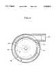
- FIG. 2is a sectional front elevation of a first embodiment of a bubble separating apparatus according to the present invention
- FIG. 3is a sectional plan view taken along line I--I in FIG. 2;
- FIG. 4is a sectional front elevation of the second embodiment of a bubble separating apparatus according to the present invention.
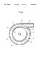
- FIG. 5is a sectional front elevation of the third embodiment of a bubble separating apparatus according to the invention.
- FIG. 6is a section taken along line III--III of FIG. 5.
- FIGS. 2 and 3show the first embodiment of a bubble separating apparatus according to the present invention.
- a vortical flow chamber 21is defined in a cone-shaped container 20 having opposite closed ends.
- the larger diameter end of the cone-shaped container 20is the lower end.
- an annular preliminary vortical flow passage 22is formed integrally with the container 20.
- the preliminary passage 22communicates with a liquid supply inlet 23 at one end which will be hereinafter referred to as inlet side end.
- a flow guide member 24is provided at the other end of the preliminary passage 22 positioned in the vicinity of the inlet side end, which other end of the preliminary passage will be hereafter referred to as outlet side end.
- the preliminary passage 22communicates with the chamber 21 via a single opening 25 positioned at the outlet side end thereof.
- the flow guide member 24has a flow guide surface extending substantially in a tangential direction to the inner periphery of the chamber 21 at the opening 25, so that the liquid is introduced into the chamber 21 from the preliminary passage 22 in a tangential direction.
- the container 20has a plurality of small holes 26 formed through the peripheral wall in substantially an upper half of the container.
- the container 20is disposed in an outer vessel 27 so that the liquid discharged through the small holes 26 is received within the outer vessel 27.
- the outer vessel 27is formed integrally with the container 20 and the preliminary passage 22. The liquid received in the outer vessel 27 is discharged through a liquid discharge outlet 28.
- a center conduit pipe 29is disposed along the center axis of the chamber 21 in the container 20, along the center axis of the chamber 21 in the container 20, a center conduit pipe 29 is disposed.
- the center conduit pipe 29is formed with a plurality of orifices 30 for connecting the interior space of the center conduit pipe and the chamber 21.
- the lower end of the center conduit pipe 29is extended through the lower end of the container 20 and the bottom of the outer vessel 27.
- the center conduit pipe 29is adapted to capture fine bubbles concentrated toward the center portion of the chamber 21 by centrifugal force exerted due to vortical flow of the liquid within the chamber 21.
- the liquid containing concentrated bubbles flowing into the center conduit pipe 29 through the orifices 30is fed to a bubble discharge outlet 31.
- the liquidis pressurized by means of a pump and introduced through the liquid supply inlet 23 into the preliminary passage 22. Then, the liquid flows through the preliminary passage 22 to reach its outlet side end.
- the inlet side end and outlet side end of the preliminary passage 22are located in close proximity to each other, so that the liquid in the preliminary passage 22 flows substantially the entire circumference of the container 20. During this travel, since the liquid flows substantially in a circumferential direction, it is subject to centrifugal force. Due to a difference in density, a fraction of the liquid containing bubbles accumulates at the inner portion of the preliminary passage 22 and flows substantially along the inner wall defining the passage 22. On the other hand, the fraction of liquid having high density and thus having less bubbles concentrically flows substantially along the outer wall of the preliminary passage 22.
- preliminary bubble-liquid separationcan take place within the preliminary passage 22 to form laminar flows of a high density liquid fraction containing less bubbles and a low density fraction containing concentrated bubbles. Furthermore, concentration of the bubble containing fraction of the liquid adjacent the inner portion of the preliminary passage 22 causes mutual collision of bubbles whereby a plurality of fine bubbles are combined or united together to form greater size bubbles. Thus, during flow in the preliminary passage 22, size of the bubbles can be enlarged.
- the liquid reaching the outlet side end of the preliminary passage 22is guided by the flow guide member 24 and deflected into the chamber 21.
- the flow guide member 24since the guide surface of the member 24 extends substantially in a tangential direction to the inner periphery of the chamber at the edge facing the opening 25, the flow guide member 24 does not substantially affect the flow of the liquid. Therefore, the liquid is introduced into the chamber 21 without causing any noticeable deceleration of the flow velocity while maintaining laminar flows of the fractions. Since the flow velocity is substantially maintained without any noticeable deceleration upon introduction into the chamber 21, and since the liquid is introduced in a tangential direction through the single opening 25, strong vortical flow can be generated in the chamber 21.
- the chamber 21serves as a kind of cyclone to cause acceleration of the vortical flow velocity toward the narrower upper end, and the bubble containing fraction of the liquid is further concentrated into the vortex center to cause further combination of a plurality of bubbles to form further greater size bubbles. Accordingly, the low density fraction of the liquid containing concentrated bubbles can be efficiently removed and discharged through the center conduit pipe 29. On the other hand, the high density fraction of the liquid containing substantially no bubble flows into the vessel 27 via the small holes 26 to be discharged through the discharge outlet 28.
- the bubble containing liquidis prepared by injecting through a fine nozzle high pressure air into the hydraulic oil which is being agitated at high speed. As a result, fine bubbles of approximately 100 ⁇ m diameter were generated in the hydraulic oil. The bubble content was approximately 10% by volume.
- the liquid thus preparedwas pressurized by a pump and supplied to both of the first embodiment of the bubble separating apparatus and the prior art apparatus of FIG. 1 for comparing the degree of removal of the bubbles.
- the bubble removal ratiois derived through the following equation. It should be noted that bubble content was measured employing a device disclosed in Japanese Unexamined Patent Publication (Kokai) No. 4-172230. The disclosure of the above-identified publication is herein incorporated by reference. ##EQU1## where Br: bubble removal rate (vol. %)
- the discharge oil in the table 1was supplied to a hydraulic device, and a hydraulic pressure generated in the hydraulic device was measured for determining the influence of bubbles in the hydraulic oil. It should be noted that measurement of the hydraulic pressure was performed at the discharge side of a high pressure pump incorporated in the hydraulic device.
- FIG. 4shows the second embodiment of the bubble separating apparatus according to the present invention.
- the shown embodiment of the apparatushas a construction divided into two segments at a portion indicated by line II--II and fastened by bolts 40.
- Other constructionis the same as the first embodiment and need not be discussed in detail again.
- the shown constructionis advantageous in facilitating cleaning and maintenance of the apparatus by permitting separation into two segments.
- the shown embodimentsprovide the liquid supply passage acting as the preliminary passage extending along substantially the entire circumference of the container 21, the high density fraction and bubble containing low density fraction of the liquid can be separated to form laminar flows by the action of centrifugal force during travel through the preliminary passage. Furthermore, the bubbles are concentrated in the vicinity of the inner wall defining the passage and collide to each other to cause combination for forming greater size bubbles.
- the liquidpasses through the preliminary passage into the chamber through a single opening, disturbance of the liquid flow can be minimized so that the liquid can be introduced into the chamber while maintaining sufficient flow energy. This enables a vortical flow strong enough for efficiently removing the bubbles to be generated.
- FIG. 5shows a third embodiment of the bubble separating apparatus according to the present invention.
- the like reference numerals to the former embodimentrepresent like elements.
- the embodiment illustrated in FIG. 5provides liquid flow rate regulation for further enhancing or optimizing bubble separating performance of the apparatus according to the present invention. Namely, as set forth in the introductory part of the disclosure, it is essential for the vortical flow type bubble separating apparatus to generate a strong vortical flow for efficiently removing bubbles from the liquid.
- liquid flow velocity and angular velocity as introduced into the chamberare important.
- the operation of the pump pressurizing the liquidfluctuates to vary the liquid flow rate, vortical flow condition in the chamber is inherently varied to cause variation of the bubble removal performance.
- the liquid flow velocity and angular velocitybecome lower, resulting in a reduced vortical flow energy. Then, the centrifugal force for separating the high density bubble-eliminated fraction and the low density bubble-containing fraction becomes insufficient.
- the liquid flow rateis excessively large, the vortical flow velocity of the liquid in the chamber becomes excessively high, the dwell time, in which the liquid stays in the chamber, becomes too short to successfully separate the bubble containing fraction. Therefore, it is desirable to regulate the liquid flow velocity and angular velocity as introduced into the chamber.
- the embodiment illustrated in FIG. 5incorporates a liquid supply regulation mechanism arranged within the outer vessel 27 below the chamber 21.
- the liquid supply regulation mechanismcomprises a plunger 50, a piston 51, a piston rod 52 connecting the plunger 50 and the piston 51, a spring 53 provided between the bottom of the apparatus and the bottom of the piston 51 for providing upward bias force for the piston, a pilot pressure chamber 54, a reference pressure chamber 55, a pilot pressure conduit 56 for introducing the pressure in the preliminary passage 22 in the vicinity of the liquid supply inlet 23, and a reference pressure introduction passage 57.
- the plunger 50has a diameter substantially corresponding to the lower larger diameter end of the container 20 for substantially closing that end. Also, the plunger 50 is formed to have a thickness necessary for at least partially blocking the opening 25. The plunger 50 moves reciprocally according to the action of the piston 51 for varying the flow path area of the opening 25.
- the upper end plane of the plunger 50defines the bottom of the chamber 21 and has formed in the center portion thereof a recess 50a for accommodating the lower end of the center conduit pipe 29 when the plunger is shifted upwardly.
- the reference pressure introduction passage 57extends through the plunger 50 in the vicinity of its circumference and further extends between the wall of the outer vessel 27 and a partitioning wall 58. This passage 57 communicates with the reference pressure chamber 55 which is defined by the partitioning wall 58, the piston 51 and the bottom wall of the outer vessel 27, through a communication path 61 formed at the lower end of the partitioning wall 58.
- the pilot pressure conduit 56extends between the preliminary passage 22 in the vicinity of the inlet side end (see FIG. 6) and the pilot pressure chamber 54 which is defined by the partitioning wall 58, the piston 51 and the wall of the outer vessel 27 for liquid communication therebetween.
- the piston 51carries a sealing packing 60 on the outer periphery thereof for establishing a liquid tight seal to thereby separate the pilot pressure chamber 54 and the reference pressure chamber 55.
- the piston rod 52 connecting the piston 51 and the plunger 50is sealed with an annular packing 59 for blocking liquid communication between the reference pressure introduction passage 57 and the pilot pressure chamber 54.
- the supply pressure of the liquid at the preliminary passage 22is introduced into the pilot pressure chamber 54 as a pilot pressure, through the pilot pressure conduit 56.
- the pressure in the chamber 21is introduced into the reference pressure chamber 55 as a reference pressure. Therefore, upward force is exerted on the piston 51 as a composite force of the reference pressure in the reference pressure chamber 55 and the spring force of the spring 53.
- downward forceis exerted on the piston 51 by the pilot pressure in the pilot pressure chamber 54.
- the piston 51is thus located at a position where the force balance at both sides is established. Namely, at the piston position where the force balance is established, the pressures at the liquid supply inlet 23 and the chamber 21 are differentiated in a magnitude corresponding to the set force given by the spring 53.
- the increased pressuremay overcome the composite force of the reference pressure corresponding to the pressure in the chamber 21 and the spring force of the spring 53 to lower the piston 51 together with the plunger 50. Accordingly, the liquid flow path area at the inlet opening 25 as well as the volume of the chamber 21 is increased to lower the liquid pressure as introduced into the chamber. In this way, the liquid pressure as introduced into the chamber 21 can be regulated to regulate the angular velocity of the vortical flow of the liquid. Consequently, by appropriately adjusting the set force provided by the spring 53, the flow velocity and angular velocity of the liquid can be optimized for optimizing bubble removal performance.
Landscapes
- Chemical & Material Sciences (AREA)
- Chemical Kinetics & Catalysis (AREA)
- Physics & Mathematics (AREA)
- Fluid Mechanics (AREA)
- Degasification And Air Bubble Elimination (AREA)
- Cyclones (AREA)
Abstract
Description
S=(ρ1-ρg)×ω.sup.2 ×r
S=(ρ1-ρg)×v.sup.2 /r
TABLE 1______________________________________ Bubble Bubble Content (vol. %) Removal Rate Supply Discharged (vol. %)______________________________________Invention 10.0 1.0 90Prior Art 10.3 2.3 78______________________________________
Claims (19)
Applications Claiming Priority (4)
| Application Number | Priority Date | Filing Date | Title |
|---|---|---|---|
| JP5-190440 | 1993-07-30 | ||
| JP5190440AJP2766604B2 (en) | 1993-07-30 | 1993-07-30 | Bubble separation device |
| JP04660194AJP3345502B2 (en) | 1994-02-22 | 1994-02-22 | Flow rate compatible bubble separator |
| JP6-046601 | 1994-02-22 |
Publications (1)
| Publication Number | Publication Date |
|---|---|
| US5510019Atrue US5510019A (en) | 1996-04-23 |
Family
ID=26386697
Family Applications (1)
| Application Number | Title | Priority Date | Filing Date |
|---|---|---|---|
| US08/280,941Expired - Fee RelatedUS5510019A (en) | 1993-07-30 | 1994-07-27 | Bubble separating apparatus |
Country Status (5)
| Country | Link |
|---|---|
| US (1) | US5510019A (en) |
| EP (1) | EP0654292B1 (en) |
| KR (1) | KR0168897B1 (en) |
| CA (1) | CA2128968C (en) |
| DE (1) | DE69409067T2 (en) |
Cited By (30)
| Publication number | Priority date | Publication date | Assignee | Title |
|---|---|---|---|---|
| WO2001083980A1 (en) | 2000-04-25 | 2001-11-08 | Ma (Innovation) Fsis Limited | Fuel separation and injection system |
| US6398404B1 (en)* | 1998-10-02 | 2002-06-04 | Karasawa Fine Co., Ltd. | Method of producing fine particle dispersions |
| US20020174958A1 (en)* | 2001-05-25 | 2002-11-28 | Kazutaka Yanagita | Separating apparatus and processing method for plate memeber |
| US6527031B1 (en) | 1998-11-06 | 2003-03-04 | Canon Kabushiki Kaisha | Sample separating apparatus and method, and substrate manufacturing method |
| US6629539B1 (en) | 1998-11-06 | 2003-10-07 | Canon Kabushiki Kaisha | Sample processing system |
| US6672358B2 (en) | 1998-11-06 | 2004-01-06 | Canon Kabushiki Kaisha | Sample processing system |
| US6833312B2 (en) | 2001-05-25 | 2004-12-21 | Canon Kabushiki Kaisha | Plate member separating apparatus and method |
| US20050126188A1 (en)* | 2002-02-07 | 2005-06-16 | Harald Winter | Method for non-intermittent provision of fluid supercool carbon dioxide at constant pressure above 40 bar as well as the system for implementation of the method |
| US20070056889A1 (en)* | 2005-09-09 | 2007-03-15 | Cds Technologies, Inc. | Apparatus for separating solids from flowing liquids |
| US20070137488A1 (en)* | 2005-12-21 | 2007-06-21 | Streiff Felix A | Static devolatilisation apparatus and method for a liquid containing polymers |
| US20080179227A1 (en)* | 2007-01-25 | 2008-07-31 | Toyota Boshoku Kabushiki Kaisha | Bubble separator |
| CN101254489B (en)* | 2008-02-29 | 2010-04-07 | 华东理工大学 | Hydrocyclone with Improved Center Pipe and Overflow Pipe Structure |
| US20100083832A1 (en)* | 2008-10-03 | 2010-04-08 | B/E Aerospace, Inc. | Vortex waste separator apparatus |
| US20100084352A1 (en)* | 2008-10-03 | 2010-04-08 | B/E Aerospace, Inc. | Multiple vortex waste separator apparatus |
| CN1891344B (en)* | 2005-06-29 | 2010-05-12 | 日本斯频德制造株式会社 | Liquid cyclone |
| US20100187186A1 (en)* | 2007-04-03 | 2010-07-29 | Siemens Water Technologies Corp. | Systems and methods for liquid separation |
| US20100307167A1 (en)* | 2008-03-12 | 2010-12-09 | Snecma | Centrifugal de-oiler of variable flow section |
| US20110110845A1 (en)* | 2009-11-12 | 2011-05-12 | Schneider Charles A | In-line mixing apparatus for iodine extraction |
| US20110110846A1 (en)* | 2009-11-12 | 2011-05-12 | Schneider Charles A | Portable system for on-site iodine extraction from an aqueous solution |
| US20120234174A1 (en)* | 2011-03-14 | 2012-09-20 | Rollins Michael J | Deaerating method and assembly |
| US8500869B1 (en)* | 2012-06-21 | 2013-08-06 | Hamilton Sundstrand Corporation | Anti-rotation deaerator outlet diffuser |
| US8529668B2 (en)* | 2012-01-13 | 2013-09-10 | Hamilton Sundstrand Corporation | Deaerator outlet diffuser |
| US8591635B2 (en)* | 2011-12-19 | 2013-11-26 | Chrysler Group Llc | Fluid aeration-reduction system |
| US20150321122A1 (en)* | 2014-05-06 | 2015-11-12 | Stanley Whetstone | De-aerator for a water heating system |
| RU2625891C2 (en)* | 2015-08-17 | 2017-07-19 | Сергей Григорьевич Драгомиров | Hydrocyclone device for cleaning piston engine coolant from solid pollutants |
| CN111043800A (en)* | 2019-12-31 | 2020-04-21 | 山东奇威特太阳能科技有限公司 | A gas-liquid separator |
| US20210187415A1 (en)* | 2019-12-20 | 2021-06-24 | Taiwan Semiconductor Manufacturing Company, Ltd. | Device for bubble removal from viscous fluid |
| RU2757089C2 (en)* | 2017-01-13 | 2021-10-11 | Ман Трак Унд Бас Аг | Lubricant tank for hydraulic system |
| CN114934904A (en)* | 2022-06-17 | 2022-08-23 | 江苏大学 | Driven type gas-liquid separation starting device |
| GB2625502A (en)* | 2022-05-16 | 2024-06-26 | Ross Charles | Airgon |
Families Citing this family (10)
| Publication number | Priority date | Publication date | Assignee | Title |
|---|---|---|---|---|
| GB2466734B (en) | 2006-02-25 | 2010-09-08 | Cameron Int Corp | Method and apparatus for fluid separation |
| DE102011016464B4 (en)* | 2011-04-08 | 2016-12-29 | Beko Technologies Gmbh | Flow-optimized filter head |
| GB2504470B (en)* | 2012-07-27 | 2014-12-31 | Perkins Engines Co Ltd | Coolant separator |
| ES2807752T3 (en)* | 2017-06-22 | 2021-02-24 | Metso Minerals Ind Inc | Hydrocyclone separator |
| CN111672164A (en)* | 2020-06-19 | 2020-09-18 | 北京博创朔方科技有限公司 | Degassing and mixing device for casting aluminum alloy section |
| US12017157B2 (en)* | 2021-01-22 | 2024-06-25 | Pratt & Whitney Canada Corp. | Deaerator for aircraft engine and associated method of operation |
| DE102021107660A1 (en) | 2021-03-26 | 2022-09-29 | Robert Staudacher | Hydrocyclone degassing device |
| CN113210146B (en)* | 2021-05-31 | 2022-10-21 | 江西理工大学 | A hydrocyclone with self-cleaning function |
| US12330089B2 (en) | 2022-09-09 | 2025-06-17 | Pratt & Whitney Canada Corp. | Dynamic deaeration system |
| US11867357B1 (en) | 2022-09-09 | 2024-01-09 | Pratt & Whitney Canada Corp. | Deaeration conduit |
Citations (8)
| Publication number | Priority date | Publication date | Assignee | Title |
|---|---|---|---|---|
| US3747306A (en)* | 1969-09-29 | 1973-07-24 | N Wikdahl | Array of cyclonic separators |
| US3771290A (en)* | 1971-12-06 | 1973-11-13 | Armstrong Ltd S A | Vortex de-aerator |
| SU734460A1 (en)* | 1977-05-10 | 1980-05-15 | За витель | Braking clutch |
| US4390351A (en)* | 1979-08-16 | 1983-06-28 | Ishikawajima-Harima Jukogyo Kabushiki Kaisha | Gas-liquid separator |
| SU1426613A1 (en)* | 1987-03-26 | 1988-09-30 | Комсомольский-на-Амуре политехнический институт | Vortex deaerator for liquid |
| US4997556A (en)* | 1988-12-26 | 1991-03-05 | Mitsubishi Oil Co., Ltd. | Oil filter I |
| EP0507584A2 (en)* | 1991-04-03 | 1992-10-07 | Kabushiki Kaisha Opus | Method and device for removing bubbles from liquid |
| WO1993012889A1 (en)* | 1991-12-23 | 1993-07-08 | Kamyr Ab | Separating arrangement and method for counteracting foam formation |
Family Cites Families (5)
| Publication number | Priority date | Publication date | Assignee | Title |
|---|---|---|---|---|
| DE1619887C3 (en)* | 1967-09-20 | 1979-08-16 | Wilhelm Keller Gmbh & Co Kg, 7401 Nehren | Device for separating air from liquids |
| US4865632A (en)* | 1987-07-30 | 1989-09-12 | Mitsubishi Oil Co., Ltd. | Integrated separator for solid and gaseous contaminants in a fluid |
| US5000766A (en)* | 1989-05-30 | 1991-03-19 | Mitsubishi Oil Co., Ltd. | Suction system gas separator from fluid |
| JPH0751204B2 (en) | 1989-10-06 | 1995-06-05 | 三菱石油株式会社 | Air bubble separation device in liquid |
| JP2643020B2 (en) | 1990-11-05 | 1997-08-20 | 三菱石油株式会社 | Dynamic determination device for bubble content in flowing liquid |
- 1994
- 1994-07-27USUS08/280,941patent/US5510019A/ennot_activeExpired - Fee Related
- 1994-07-27CACA002128968Apatent/CA2128968C/ennot_activeExpired - Fee Related
- 1994-07-29KRKR1019940018572Apatent/KR0168897B1/ennot_activeExpired - Fee Related
- 1994-07-29EPEP94305632Apatent/EP0654292B1/ennot_activeExpired - Lifetime
- 1994-07-29DEDE69409067Tpatent/DE69409067T2/ennot_activeExpired - Fee Related
Patent Citations (9)
| Publication number | Priority date | Publication date | Assignee | Title |
|---|---|---|---|---|
| US3747306A (en)* | 1969-09-29 | 1973-07-24 | N Wikdahl | Array of cyclonic separators |
| US3771290A (en)* | 1971-12-06 | 1973-11-13 | Armstrong Ltd S A | Vortex de-aerator |
| SU734460A1 (en)* | 1977-05-10 | 1980-05-15 | За витель | Braking clutch |
| US4390351A (en)* | 1979-08-16 | 1983-06-28 | Ishikawajima-Harima Jukogyo Kabushiki Kaisha | Gas-liquid separator |
| SU1426613A1 (en)* | 1987-03-26 | 1988-09-30 | Комсомольский-на-Амуре политехнический институт | Vortex deaerator for liquid |
| US4997556A (en)* | 1988-12-26 | 1991-03-05 | Mitsubishi Oil Co., Ltd. | Oil filter I |
| EP0507584A2 (en)* | 1991-04-03 | 1992-10-07 | Kabushiki Kaisha Opus | Method and device for removing bubbles from liquid |
| JPH0584403A (en)* | 1991-04-03 | 1993-04-06 | Oopasu:Kk | Equipment and method for removing bubbles in liquid |
| WO1993012889A1 (en)* | 1991-12-23 | 1993-07-08 | Kamyr Ab | Separating arrangement and method for counteracting foam formation |
Cited By (49)
| Publication number | Priority date | Publication date | Assignee | Title |
|---|---|---|---|---|
| US6398404B1 (en)* | 1998-10-02 | 2002-06-04 | Karasawa Fine Co., Ltd. | Method of producing fine particle dispersions |
| US20040045679A1 (en)* | 1998-11-06 | 2004-03-11 | Canon Kabushiki Kaisha | Sample processing system |
| US6527031B1 (en) | 1998-11-06 | 2003-03-04 | Canon Kabushiki Kaisha | Sample separating apparatus and method, and substrate manufacturing method |
| US6629539B1 (en) | 1998-11-06 | 2003-10-07 | Canon Kabushiki Kaisha | Sample processing system |
| US6672358B2 (en) | 1998-11-06 | 2004-01-06 | Canon Kabushiki Kaisha | Sample processing system |
| US7579257B2 (en) | 1998-11-06 | 2009-08-25 | Canon Kabuhsiki Kaisha | Sample separating apparatus and method, and substrate manufacturing method |
| US6971432B2 (en) | 1998-11-06 | 2005-12-06 | Canon Kabushiki Kaisha | Sample processing system |
| WO2001083980A1 (en) | 2000-04-25 | 2001-11-08 | Ma (Innovation) Fsis Limited | Fuel separation and injection system |
| US20020174958A1 (en)* | 2001-05-25 | 2002-11-28 | Kazutaka Yanagita | Separating apparatus and processing method for plate memeber |
| US20040221963A1 (en)* | 2001-05-25 | 2004-11-11 | Canon Kabushiki Kaisha | Separating apparatus and processing method for plate member |
| US6833312B2 (en) | 2001-05-25 | 2004-12-21 | Canon Kabushiki Kaisha | Plate member separating apparatus and method |
| US6867110B2 (en) | 2001-05-25 | 2005-03-15 | Canon Kabushiki Kaisha | Separating apparatus and processing method for plate member |
| US6946052B2 (en) | 2001-05-25 | 2005-09-20 | Canon Kabushiki Kaisha | Separating apparatus and processing method for plate member |
| US20050126188A1 (en)* | 2002-02-07 | 2005-06-16 | Harald Winter | Method for non-intermittent provision of fluid supercool carbon dioxide at constant pressure above 40 bar as well as the system for implementation of the method |
| US7891197B2 (en)* | 2002-02-07 | 2011-02-22 | L'air Liquide Societe Anonyme A Directoire Et Conseil De Surveillance Pour L'etude Et L'exploitation Des Procedes Georges Claude | Method for non-intermittent provision of fluid supercool carbon dioxide at constant pressure above 40 bar as well as the system for implementation of the method |
| CN1891344B (en)* | 2005-06-29 | 2010-05-12 | 日本斯频德制造株式会社 | Liquid cyclone |
| US7465391B2 (en)* | 2005-09-09 | 2008-12-16 | Cds Technologies, Inc. | Apparatus for separating solids from flowing liquids |
| US20070056889A1 (en)* | 2005-09-09 | 2007-03-15 | Cds Technologies, Inc. | Apparatus for separating solids from flowing liquids |
| US20070137488A1 (en)* | 2005-12-21 | 2007-06-21 | Streiff Felix A | Static devolatilisation apparatus and method for a liquid containing polymers |
| US7942955B2 (en)* | 2005-12-21 | 2011-05-17 | Sulzer Chemtech Ag | Static devolatilisation apparatus and method for a liquid containing polymers |
| US7871461B2 (en) | 2007-01-25 | 2011-01-18 | Toyota Boshoku Kabushiki Kaisha | Bubble separator |
| US20080179227A1 (en)* | 2007-01-25 | 2008-07-31 | Toyota Boshoku Kabushiki Kaisha | Bubble separator |
| US20100187186A1 (en)* | 2007-04-03 | 2010-07-29 | Siemens Water Technologies Corp. | Systems and methods for liquid separation |
| US8715512B2 (en) | 2007-04-03 | 2014-05-06 | Siemens Energy, Inc. | Systems and methods for liquid separation |
| CN101254489B (en)* | 2008-02-29 | 2010-04-07 | 华东理工大学 | Hydrocyclone with Improved Center Pipe and Overflow Pipe Structure |
| US20100307167A1 (en)* | 2008-03-12 | 2010-12-09 | Snecma | Centrifugal de-oiler of variable flow section |
| US7998251B2 (en)* | 2008-10-03 | 2011-08-16 | B/E Aerospace, Inc. | Vortex waste separator apparatus |
| US7998250B2 (en)* | 2008-10-03 | 2011-08-16 | B/E Aerospace, Inc. | Multiple vortex waste separator apparatus |
| US20100083832A1 (en)* | 2008-10-03 | 2010-04-08 | B/E Aerospace, Inc. | Vortex waste separator apparatus |
| US20100084352A1 (en)* | 2008-10-03 | 2010-04-08 | B/E Aerospace, Inc. | Multiple vortex waste separator apparatus |
| US20110110846A1 (en)* | 2009-11-12 | 2011-05-12 | Schneider Charles A | Portable system for on-site iodine extraction from an aqueous solution |
| US20110110845A1 (en)* | 2009-11-12 | 2011-05-12 | Schneider Charles A | In-line mixing apparatus for iodine extraction |
| US8673143B2 (en) | 2009-11-12 | 2014-03-18 | Charles A. Schneider | Portable system for on-site iodine extraction from an aqueous solution |
| US8303163B2 (en)* | 2009-11-12 | 2012-11-06 | Schneider Charles A | In-line mixing apparatus for iodine extraction |
| US20120234174A1 (en)* | 2011-03-14 | 2012-09-20 | Rollins Michael J | Deaerating method and assembly |
| US8366809B2 (en)* | 2011-03-14 | 2013-02-05 | Hamilton Sundstrand Corporation | Deaerating method and assembly |
| US8591635B2 (en)* | 2011-12-19 | 2013-11-26 | Chrysler Group Llc | Fluid aeration-reduction system |
| US8529668B2 (en)* | 2012-01-13 | 2013-09-10 | Hamilton Sundstrand Corporation | Deaerator outlet diffuser |
| US8500869B1 (en)* | 2012-06-21 | 2013-08-06 | Hamilton Sundstrand Corporation | Anti-rotation deaerator outlet diffuser |
| US20150321122A1 (en)* | 2014-05-06 | 2015-11-12 | Stanley Whetstone | De-aerator for a water heating system |
| US10052569B2 (en)* | 2014-05-06 | 2018-08-21 | Stanley Whetstone | De-aerator for a water heating system |
| RU2625891C2 (en)* | 2015-08-17 | 2017-07-19 | Сергей Григорьевич Драгомиров | Hydrocyclone device for cleaning piston engine coolant from solid pollutants |
| RU2757089C2 (en)* | 2017-01-13 | 2021-10-11 | Ман Трак Унд Бас Аг | Lubricant tank for hydraulic system |
| US20210187415A1 (en)* | 2019-12-20 | 2021-06-24 | Taiwan Semiconductor Manufacturing Company, Ltd. | Device for bubble removal from viscous fluid |
| US11918938B2 (en)* | 2019-12-20 | 2024-03-05 | Taiwan Semiconductor Manufacturing Company, Ltd. | Device for bubble removal from viscous fluid |
| US12083450B2 (en) | 2019-12-20 | 2024-09-10 | Taiwan Semiconductor Manufacturing Company, Ltd. | Method of bubble removal from viscous fluid |
| CN111043800A (en)* | 2019-12-31 | 2020-04-21 | 山东奇威特太阳能科技有限公司 | A gas-liquid separator |
| GB2625502A (en)* | 2022-05-16 | 2024-06-26 | Ross Charles | Airgon |
| CN114934904A (en)* | 2022-06-17 | 2022-08-23 | 江苏大学 | Driven type gas-liquid separation starting device |
Also Published As
| Publication number | Publication date |
|---|---|
| KR950002862A (en) | 1995-02-16 |
| EP0654292B1 (en) | 1998-03-18 |
| CA2128968C (en) | 2000-05-02 |
| EP0654292A2 (en) | 1995-05-24 |
| EP0654292A3 (en) | 1995-06-07 |
| DE69409067T2 (en) | 1998-10-29 |
| CA2128968A1 (en) | 1995-01-31 |
| DE69409067D1 (en) | 1998-04-23 |
| KR0168897B1 (en) | 1999-01-15 |
Similar Documents
| Publication | Publication Date | Title |
|---|---|---|
| US5510019A (en) | Bubble separating apparatus | |
| US4378289A (en) | Method and apparatus for centrifugal separation | |
| CA1045083A (en) | Hydrocyclone | |
| KR930009499B1 (en) | Rotary Vortex Separator for Heterogeneous Fluids | |
| US5019136A (en) | Method and apparatus for separating gas with a pump from a medium being pumped | |
| US5500039A (en) | Gas-liquid separating apparatus | |
| KR950006504B1 (en) | Oil separator | |
| US4280902A (en) | Separation of dense impurities from a fluid | |
| US6827820B1 (en) | Degassing centrifugal apparatus, process for pumping and degassing a fluid and process for producing paper or board | |
| US3199270A (en) | Apparatus for mixing and separating substances of different mass-inertia | |
| US6398139B1 (en) | Process for fluidized-bed jet milling, device for carrying out this process and unit with such a device for carrying out this process | |
| US5240477A (en) | Method and device for removing bubbles from liquid | |
| IE53570B1 (en) | Compressor system | |
| US5427685A (en) | Separator for separating gas from a liquid | |
| US5049171A (en) | Oil/air separator | |
| US4631871A (en) | Abrasive fluid jet apparatus | |
| US4865633A (en) | Separator | |
| US4643746A (en) | Apparatus for separating gas from fluid | |
| US2748668A (en) | Separator-pumping operation for paper stock | |
| US3716137A (en) | Cyclone separator | |
| EP0049789A1 (en) | Screening apparatus | |
| JPH07232004A (en) | Flow rate compatible bubble separator | |
| US3463318A (en) | Centrifuging device for separating a mixture into solids and liquid | |
| JP2002506135A (en) | Screen device with two screen chambers for fiber suspension separation | |
| RU2212281C1 (en) | Hydraulic cyclone |
Legal Events
| Date | Code | Title | Description |
|---|---|---|---|
| AS | Assignment | Owner name:MITSUBISHI OIL CO., LTD., JAPAN Free format text:ASSIGNMENT OF ASSIGNORS INTEREST;ASSIGNORS:YABUMOTO, JUNSUKE;HIROSE, MASANORI;REEL/FRAME:007093/0064 Effective date:19940706 | |
| FEPP | Fee payment procedure | Free format text:PAYOR NUMBER ASSIGNED (ORIGINAL EVENT CODE: ASPN); ENTITY STATUS OF PATENT OWNER: LARGE ENTITY | |
| FPAY | Fee payment | Year of fee payment:4 | |
| AS | Assignment | Owner name:NIPPON MITSUBISHI OIL CORPORATION, JAPAN Free format text:MERGER AND CHANGE OF NAME;ASSIGNOR:MITSUBISHI OIL CO., LTD.;REEL/FRAME:010470/0094 Effective date:19990803 | |
| FEPP | Fee payment procedure | Free format text:PAYER NUMBER DE-ASSIGNED (ORIGINAL EVENT CODE: RMPN); ENTITY STATUS OF PATENT OWNER: LARGE ENTITY Free format text:PAYOR NUMBER ASSIGNED (ORIGINAL EVENT CODE: ASPN); ENTITY STATUS OF PATENT OWNER: LARGE ENTITY | |
| FPAY | Fee payment | Year of fee payment:8 | |
| REMI | Maintenance fee reminder mailed | ||
| LAPS | Lapse for failure to pay maintenance fees | ||
| STCH | Information on status: patent discontinuation | Free format text:PATENT EXPIRED DUE TO NONPAYMENT OF MAINTENANCE FEES UNDER 37 CFR 1.362 | |
| FP | Lapsed due to failure to pay maintenance fee | Effective date:20080423 |