US5508940A - Random access audio/video processor with multiple outputs - Google Patents
Random access audio/video processor with multiple outputsDownload PDFInfo
- Publication number
- US5508940A US5508940AUS08/196,018US19601894AUS5508940AUS 5508940 AUS5508940 AUS 5508940AUS 19601894 AUS19601894 AUS 19601894AUS 5508940 AUS5508940 AUS 5508940A
- Authority
- US
- United States
- Prior art keywords
- video
- buffer
- coupled
- audio
- present
- Prior art date
- Legal status (The legal status is an assumption and is not a legal conclusion. Google has not performed a legal analysis and makes no representation as to the accuracy of the status listed.)
- Expired - Lifetime
Links
Images


Classifications
- G—PHYSICS
- G11—INFORMATION STORAGE
- G11B—INFORMATION STORAGE BASED ON RELATIVE MOVEMENT BETWEEN RECORD CARRIER AND TRANSDUCER
- G11B27/00—Editing; Indexing; Addressing; Timing or synchronising; Monitoring; Measuring tape travel
- G11B27/02—Editing, e.g. varying the order of information signals recorded on, or reproduced from, record carriers
- G11B27/031—Electronic editing of digitised analogue information signals, e.g. audio or video signals
- H—ELECTRICITY
- H04—ELECTRIC COMMUNICATION TECHNIQUE
- H04N—PICTORIAL COMMUNICATION, e.g. TELEVISION
- H04N5/00—Details of television systems
- H04N5/222—Studio circuitry; Studio devices; Studio equipment
- H04N5/262—Studio circuits, e.g. for mixing, switching-over, change of character of image, other special effects ; Cameras specially adapted for the electronic generation of special effects
Definitions
- the present inventionrelates to the field of audio/video processors, storage devices and servers, and more particularly, to random access audio/video systems.
- Video editing systemshave evolved from providing simple editing cuts to the incorporation of full feature graphics, film-to-tape, and other processes to complete a video production.
- Non-linear random access video editing systemspermit access to any video frame from any location on the storage media and rearrangement of the frame into a desired output.
- the coupling of computer technology with video tape editing systems, as well as multimedia hardware and software support, including, by way of example, CD ROM technology, magnetic storage media and graphic user interface technologypermits the editor to incorporate and integrate various production media resources such as special effects, music, graphics, and the like into a production.
- One of the requirements of any multimedia video/audio editing systemis to provide the operator with the ability to manage large quantities of information in an understandable and efficient manner.
- the systemmust be flexible, and intuitive, to accommodate a variety of operator editing styles and personalities.
- Various video tape editing systemshave been developed in the past, for example the Sony BVE 9000 manufactured by Sony Corporation of Tokyo, Japan, and those systems described, for example, in U.S. Pat. Nos. 5,262,865, 5,148,514 and U.S. Pat. No. 4,538,188.
- the present inventionprovides a multimedia random access audio/video editing system, heretofore unknown in the prior art, which allows users to configure the editing system to suit their needs.
- the present inventionpermits the storage of large amounts of source material and emulates many existing video tape recorders.
- the present inventionprovides high quality audio and video material, and includes a variety of on-line, real-time, audio and video effects.
- the architecture of the present inventionis modular, such that it may be upgraded to take advantage of improved storage and compression technology which may be developed in the future.
- the present inventionmay be utilized in electronic newsroom settings for providing access to source material to multiple editing stations. The edited material may then be coupled directly to, for example, an electronic publishing system, a television transmitting system, or a cable head end.
- a random access audio/video processor with multiple outputsis disclosed.
- dual source video tape recordersprovide original source material and are coupled to the inputs of a main control unit.
- a video effects deviceis coupled to the video outputs of the main control unit. The outputs of the video effects device are run to a record video tape recorder (VTR), and to a video monitor.
- An audio effects deviceis coupled to the audio outputs of the main control unit. The outputs of the audio effects device are run to the record VTR, and to a pair of audio monitors.
- the video effects devicecomprises a Sony DFS 500 DME Switcher
- the audio effects devicecomprises a "Mark of the Unicorn" audio mixer.
- a personal computeris coupled to the main control unit. Magnetic (or optical) mass storage devices are coupled to the main control unit, and are used for storage of digitized audio and video material.
- the main control unit of the present inventionincludes an analog video back panel and an analog audio back panel coupled, respectively, to an analog input/output (I/O) board.
- the analog I/O boardis coupled to a video processing board and to an audio processing board.
- the video processing boardincludes a compressor for compressing input video signals and storing the compressed signals in a triple transfer buffer.
- two video triple transfer buffersare coupled to a bus which is further coupled to a direct memory access (DMA) device for accessing, storing and retrieving video data from the magnetic disk.
- DMAdirect memory access
- the video processing boardfurther includes decompression circuits coupled to each of the triple transfer buffers for decompressing compressed stored video and providing the decompressed video channels (Channel A and Channel B) to an effects board for the addition of special effects, as desired by the editor.
- the output of the effects boardis coupled to the analog I/O board and through the analog video back panel to the record VTR.
- two channels of audiomay be input to the control unit of the present invention for digitization and storage on the magnetic disks.
- two triple transfer buffersare provided for the respective audio channel inputs. On the output side, a total of four triple transfer buffers are provided, one for each of the four audio outputs of the present invention.
- the video processing and audio processing boardsare coupled to a system board including DMA devices for accessing the video and audio data stored on the magnetic disks, and a central processing unit (CPU) for coordinating the fetching and storing of video and audio data over the various busses, completion of file formatting operations, and the maintenance of various logs for identifying video and audio digitized data stored on the video and audio magnetic disks.
- DMA devicesfor accessing the video and audio data stored on the magnetic disks
- CPUcentral processing unit
- the triple transfer buffers of the present inventioninclude a present buffer, a past buffer, and a future buffer.
- the purpose of the triple transfer buffers of the present inventionis to ensure that there is sufficient video and audio material in the present buffers to play (at video and at audio rates), such that the user will be not perceive any discontinuities in either the audio or the video channel outputs.
- the end of the present bufferis reached, the future buffer becomes the new present buffer, the past buffer becomes the new future buffer, and the present buffer becomes the new past buffer. If the user desires to view video frames in a reverse direction, the opposite progression will occur.
- An additional aspect of the present inventionis that a user may view video which has been compressed and decompressed to verify that no unwanted system artifacts exist or are being created by the compression process.
- the viewing of the compressed and decompressed materialis done in real-time while the material is actually being compressed by the compressor circuit of the video processing board.
- the architecture of the present inventionpermits a user to monitor the effect of the compression in real-time during the storage process of the video signal.
- An additional feature of the present inventionis its ability to play back two separate independent outputs from a common pool of recorded source material. When playing back two independent outputs, only half of the total disk bandwidth is used for each channel. Alternatively, the present invention permits maximum video quality by utilizing the entire bandwidth of the video disk for the display of a single output channel.
- a further aspect of the present inventionis that, under software control, a user may bypass the compression circuit and capture uncompressed still frames directly in the triple transfer buffer, and store the uncompressed stills on the video disk.
- Independent transfer buffers and control logicpermit the display of both still and motion video on each respective output channel wherein the playback speed and timing of each channel may be independently adjusted.
- Another feature of the systemis the implementation of the media pipeline which provides the ability to store and retrieve high quality video, and allows video to be looped from the decompressor back to the compressor and then stored on the video disk.
- the editoris provided with a real-time effects preview capability.
- the present inventionallows the editor to quickly recompress the video such that, for example, a frame stored at 100 kilobytes, followed by an effect using two frames stored at 50 kilobytes, and a subsequent frame of 100 kilobytes may be provided.
- the present inventioncan create the effect in software using 100 kilobyte frames, thereby maintaining the quality of the effect to match that of the video quality of the standard frames before and after the effect in the sequence of video frames.
- This featureallows both real-time effects at a reduced quality, or real-time effect previews. The preview may then be followed by a software assisted full quality effect.
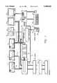
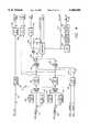
- FIG. 1illustrates a block diagram of a system configuration for one embodiment of the present invention.
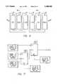
- FIG. 2illustrates a flow diagram of the media pipelines comprising the present invention.
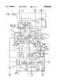
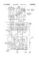
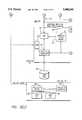
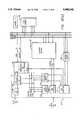
- FIGS. 3a, 3b, 3c and 3dillustrate a block diagram of the circuit components comprising the present invention.
- FIG. 4is a circuit block diagram illustrating the compression circuitry for the video processing board of the present invention.
- FIG. 5is a circuit block diagram illustrating the decompression circuitry for the video processing board of the present invention.
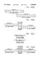
- FIG. 6diagramatically illustrates the present invention's use of triple transfer buffers for video and audio processing.
- FIG. 7is a block diagram illustrating in conceptual form the architecture of the effects circuitry of the present invention.
- FIG. 8is a more detailed block diagram illustrating the effects board comprising the present invention for the generation of special effects.
- FIGS. 9a and 9bare block diagrams illustrating the audio processor circuitry of the present invention.
- FIGS. 10a through 10dillustrate the present invention's use of the loop back circuit and recompression to optimize the video bandwidth for real-time previews and effects.
- FIG. 11illustrates the present invention's method for applying timing relationship adjustments during the effect preview.
- the present inventionis illustrated in one possible configuration of interconnected elements.
- the present inventionmay be considered as an audio/video processor, where audio and video source material are processed and stored on either a hard disk, CD ROM, magnetic media or other combination of storage media.
- the present inventionpermits the audio and video material to be accessed, on a frame by frame basis, quickly from any location on the storage media, and rearranged into a desired output for video/audio editing.
- the present inventionallows the user to edit material and to view the final output in real-time, without having to linearly record source clips on a piece by piece basis to a separate machine for later viewing.
- the present inventiondoes not require that the original source material be modified, edited or otherwise rearranged, and thereby maintains the source material in its original form.
- the present inventionallows effects and timing relationships to be modified between multiple streams of material, in real time, and provides high quality reproduction during single stream playback.
- the output of the present inventionmay be used as the final combined material, or as a real time preview for editing.
- dual source video tape recorders (VTRs) 10 and 12provide original source material to the system illustrated in the figure.
- a record VTR 14records the edited audio/video material for later viewing.
- the record VTR 14is coupled to an effects device 16, which in the presently preferred embodiment, comprises a Sony DFS 500 DME Switcher.
- the record VTR 14is further coupled to a monitor 20 for displaying video material recorded and stored on the VTR 14.
- the system of the present invention as illustrated in FIG. 1further includes a computer 25, which, in the presently preferred embodiment, comprises a personal computer (“PC") utilizing a 486 (66 megahertz) Intel® microprocessor.
- PCpersonal computer
- a video monitor 28is coupled to the computer 25 for the display of a graphic user interface such as that disclosed in U.S. patent application Ser. No. 08/021,872, filed Feb. 24, 1993 and entitled “Graphical User Interface Incorporating A Horizontal Panning Workspace", as well as Ser. No. 08/047,828, filed Apr. 15, 1993 and entitled “A Re-Edit Function Allowing By-Directional Rippling", and Ser. No. 08/047,825, filed Apr. 15, 1993 and entitled “Time Based Visual Display of Multiple Track Interrelationships And Available Material During Re-Edit Functions" U.S. Pat. No. 5,339,393, and Ser. No. 08/024,271, filed Feb. 26, 1993 and entitled “A Card File Graphical User Interface With Visual Representation Of Video Data”.
- a keyboard 30is coupled to the computer 25 for providing input commands to the computer 25, as is well known.
- a cursor control device (“mouse”) 32is also coupled to the computer 25, for controlling the position of a cursor on the display 28.
- a control center 34including a shuttle knob 36, fader bar 38, and other various controls is coupled to a device controller 40.
- the device controller 40provides control signals to other video tape recorders, DME and mixing devices and the like, and is further coupled to the computer 25 as shown.
- the computer 25is coupled over a "SCSI" bus 50 to a main control unit 60.
- the main control unit 60receives data and commands over the bus 50 from the computer 25 in the form of play lists and/or direct commands.
- the main control unit 60is coupled to VTR 10 over video line 62, VTR 12 over video line 64, and the effects unit 16 over video lines 66 and 67.
- the main unit 60is further coupled to an audio mixer 70 over four audio lines 72.
- the audio mixer 70drives speakers 80 and 82 to permit the editor to listen to audio edits completed using the system illustrated in FIG. 1,
- the control unit 60is further coupled to a magnetic (or optical) mass storage device 84, and optional mass storage devices 86 and 89, as shown.
- FIG. 1the configuration of the present invention as illustrated in FIG. 1 is representative of one of many possible configurations which may be utilized in accordance with the teachings herein.
- the components illustrated in FIG. 1may be rearranged, and, the main control unit 60 may be used in conjunction with other known components not illustrated.
- the system of the present inventionis based upon a media pipeline which comprises a storage device 90, such as for example, the magnetic disk 84 illustrated in FIG. 1.
- a "SCSI" interface 92couples the control unit 60 to the storage device 90.
- a direct memory access (“DMA") controller 94is coupled to the SCSI interface 92 and to a triple transfer buffer 96.
- a media processing functional block 99is coupled to the triple transfer buffer 96, as well as input/output (I/O) circuitry 100.
- the I/O circuitry 100receives and transmits video information from an external device. Similarly, as illustrated in FIG.
- an external deviceis coupled to an audio I/O circuitry 102 for receiving audio signals.
- a media processing block 104is coupled to the I/O circuitry 102 and to an audio triple transfer buffer 106 as shown.
- An audio DMA controller 110is coupled to a SCSI interface 112 for controlling the storage and retrieval of audio data in a storage device 119.
- a switch 120controls the transfer of video and audio data in the pipelines, and permits the sharing of storage devices, buffers and the like between video and audio data, as will be described more fully herein.
- the overall purpose of the media pipelinesis to move video and audio data quickly from one end of the pipeline to the other.
- the pipelinemay move data at approximately 20 Mega Bytes per second.
- the present inventionstores compressed video information and uncompressed audio and requires, in the current embodiment, only 96 kilobytes per second throughput for each audio channel. Accordingly, the present invention is capable of handling multiple streams of audio and video data in real-time.
- the structure of the present inventionpermits compressed video resampling to allow higher bandwidth throughput, and the simultaneous playback of multiple streams of material without exceeding the bandwidth limits of the media channel.
- the present implementationsupports two output video channels and four output audio channels simultaneously.
- the media pipelines of the present inventionare not limited to only two channels of video and four channels of audio, and alternate implementations of the present invention may be provided to enhance the number of video and audio channels available.
- alpha numeric time code informationmay optionally be overlaid directly into either or both of the video outputs.
- the main control unit 60includes an analog video back panel 150 and an analog audio back panel 152.
- an analog I/O board 155is provided to couple video data to and from a video processing board 158, and an effects board 160.
- an audio processing board 162is provided to an audio processing board 162 as shown in FIG. 3b.
- Video and audio DMA control signalsare provided, respectively, by a system board 166 which is in turn coupled to the video disks 380 (including for example disk 84 of FIG. 1) and audio disks 410 (such as for example disk 86, or alternatively, a portion of disk 84 in FIG. 1 ).
- a sync generation board 170provides synchronization and control signals to the various boards illustrated in FIGS. 3a through 3d.
- source VTRs 10 and 12provide analog video signals to the board 150.
- the present inventionprovides the ability to bypass the control unit 60 by selectively routing signals from VTR 10 and VTR 12 directly through switches 200 and 202 to the video outputs A (67 in FIG. 1) and B (66 in FIG. 1 ), as shown.
- the analog video back panel 150acts as a bypass through the system.
- the analog audio back panel 152receives four audio input channels 204, 206, 208 and 210.
- four audio outputsmay be directly routed and thereby bypass the control unit 60, namely, audio outputs 220, 222, 224 and/or 226.
- a switch 230 in the analog video back panel 150selects which video channel (for example a video channel from VTR 10 or VTR 12) to be coupled to the analog I/O board 155 over a line 231.
- an RGB graphics circuit 235provides RGB-in signals for use in the generation of graphics.
- a key-in signal circuit 240is provided for luma key, as is known in the art. In operation, the RGB graphics signal 235 is passed through the analog I/O board 155 and coupled to the effects board 160 for use in effects such as wipe, mix and the like.
- the video channel coupled to the analog I/O board 155 from the analog video back panel 150is provided to a video decoder 250 for decoding the video signal, and is in turn coupled to an analog to digital (A/D) converter 255 to convert the analog video signal to a digital video signal.
- the digital video signalis then coupled to a formatter 260 for providing the digital video signal in the correct format for use in the system of the present invention.
- the RGB graphics signal 235is coupled over a line 261 to art RGB-in port on the analog I/O board 155 and to an RGB analog to digital (A/D) converter 266 which converts the signal into a digital form.
- the RGB digital signal from the RGB A/D converter 266is coupled to the formatter 260 for proper formatting into a digital format.
- the key-in signal 240is coupled to a video decoder 270 over line 271 and an A/D converter 272.
- the digitized key-in signalis then coupled to a formatter 274 to be placed in the proper format for the digital system of the present invention.
- a receiver 300is provided on the analog I/O board 155 for receiving synchronization and clock signals from the sync generator circuit 170.
- the analog I/O board 155receives two audio channels selected from the four input audio channels 204, 206, 208 and 210 using switches 305 and 310.
- the input audio channels 312 and 314are coupled to an audio decoder 316, a delay circuit 317 to match the delay of the video (for synchronization purposes), and a format circuit 319 to provide the audio signals in the correct format.
- the output of the analog I/O board 155comprises a 1-bit audio line 320 for the two digitized audio channels.
- the output of formatter 260comprises a 20-bit parallel digital video signal coupled over a video input bus 330.
- a digitized key signal output from the formatter 274is coupled to a 10-bit wide key bus 332 as shown.
- the video signal over bus 330, and the key signal over bus 332are coupled to the video processing board 158.
- a primary purpose of the video processing board 158is to compress and decompress, as well as cache, the video signal input from bus 330, and video signals retrieved from the video disks 380.
- the video signal coupled over bus 330is provided to a resync buffer 350.
- the resync buffer 350provides resynchronization for the video signals input into the video processing board 158, such that the video signals are synchronized to the output side of the control unit 60. Additionally, as shown, the digitized and formatted key signal coupled over bus 332 to the video processing board 158 is also coupled to a resync buffer 352. The resynchronized video from resync buffer 350 is coupled to a compressor circuit 360, which in the presently preferred embodiment utilizes standard JPEG compression.
- the compressed videois then coupled from the compressor 360 to a triple transfer buffer denoted generally by the numeral 362.
- the triple transfer buffercomprises dual port video RAM (VRAM).
- the triple transfer bufferscomprise a buffer for the past, the present and the future, as will be described in more detail below.
- the compressed video data stored within the triple transfer buffer 362may be accessed over a DMA bus 370 (comprising a 22-bit wide parallel bus), and are controlled through a DMA controller 372.
- a SCSI controller 374controls the interface between the video disks 380 (for example disks 84, 86 and or 89 in FIG. 1) and the system board 166.
- system board 166includes a synchronization receiver 382 for receiving synchronization signals from the synchronization generator 170, as does the video processor board 158 (receiver 384 in FIG. 3a), and the audio processor board 162.
- digitized audio data from the formatter 319 coupled to the single bit line bus 320is provided to the audio processor board 162.
- the digitized audiois coupled to a digital signal processor ("DSP") 390 on the audio processor board 162, and is coupled to a triple transfer buffer 392 and a triple transfer buffer 394, for each audio channel input into the analog I/O board 15,5, respectively.
- DSPdigital signal processor
- the present inventiondoes not compress audio signals, but rather stores uncompressed digital audio in the transfer buffers 392 and 394 and audio disks 410.
- the digital audiois accessed by a DMA controller 400 over a DMA bus (in the present embodiment, a 22-bit wide bus) 402 as illustrated in FIGS. 3b and 3d.
- a SCSI controller 406is coupled to the DMA 400, and provides control and interface signals to store and retrieve the digital audio signals from the audio disks 410.
- the video disks 380 and audio disks 410may be implemented as a single magnetic disk (for example, disk 84) or comprise separate disks.
- a central processing unit (CPU) 415is coupled to the DMA units 372 and 400, as well as the SCSI controllers 374 and 406, and provides control signals for the various DMA and SCSI devices, as well as general coordination for the entire system operation.
- system control commandsare provided by the CPU 415 to the various components on the analog I/O board 155, video processing board 158, audio processing board 162, and sync generator board 170 over a VME control bus 420.
- each of the boards comprising the invention illustrated in FIGS. 3a through 3dincludes a VME interface circuit for receiving the control signals and communicating with the CPU 415.
- the analog I/O board 155includes a VME interface circuit 422
- the video processing board 158includes a VME control circuit 430
- the audio processing board 162includes a VME interface circuit 435
- the system board 166includes a VME interface circuit 440
- the sync generator board 170include a VME interface circuit 442.
- the CPU 415controls the coordination of the fetching and storing of video and audio data over the DMA busses 370 and 402, completes file formatting operations for both the video disks 380 and audio disks 410, maintains various logs for identifying what video and audio digitized data is stored on the video disks 380 and audio disks 410, and generally executes the software required to effectuate the present invention as described in this Specification.
- the CPU 415is shown as a single block in FIG. 3. However, it will be appreciated by one skilled in the art, that additional components such as read-only memory, a microprocessor, random access memory, control signals, devices and the like are not shown in order not to obscure the present invention unnecessarily.
- the sync generator board 170includes synchronization and clock drivers 500 which are coupled to a synchronization and clock generator circuit 502.
- a video phase lock loop 504, and an audio phase lock loop 505are also coupled to the sync and clock generation circuit 502.
- a sync stripper 504is provided for stripping synchronization signals from an external reference 510.
- circuitryis provided within the sync generator board 170 to provide a black burst out signal 512, as is known in the art.
- the sync generator board 170is responsible for providing synchronization and clock signals to the system illustrated in FIGS. 3a through 3d.
- Datais read from the video disks 380 and audio disks 410 in data "chunks".
- two video channelsare read from the video disk 380 by the DMA 372 and are coupled to the DMA bus 370 during playback.
- video stored on the video disks 380are in a JPEG compressed format.
- Each of the video channelsare stored, respectively, in the triple transfer buffer 362, and a second triple transfer buffer 530.
- four audio channelsare read by the DMA controller 400 from the audio disks 410.
- the audio channelsare coupled over the DMA bus 402 to triple transfer buffers 392, 394, and transfer buffers 535 and 540, respectively.
- Each audio channelis stored in one of the four triple transfer buffers illustrated in FIG. 3b.
- the triple transfer bufferscomprise video RAM memories which are used to smooth out inconsistencies in the flow of data on both the audio and video processing sides of the control unit 60.
- video RAM memorieswhich are used to smooth out inconsistencies in the flow of data on both the audio and video processing sides of the control unit 60.
- a bufferis required to hold the data which is currently being played, while the video to be played next is loaded.
- thiswould require that the transfer buffers be divided into two parts.
- a usermay decide at any moment to begin playing video in reverse from the present location or frame being viewed. Therefore, the present invention has divided the transfer buffers into three logical blocks as shown in FIGS. 3a, 3b and 6.
- each of the video transfer buffers(for example, buffer 362 and 530, as well as audio transfer buffers 392, 394, 535 and 540) include a present buffer 600, a past buffer 602, and a future buffer 604.
- triple transfer buffer 530includes a present buffer 606, a past buffer 608, and a future buffer 610, as shown in FIG. 6.
- the operation of the audio transfer buffersis similar to that of the video transfer buffers shown in FIG. 6, and will, therefore, not be described in further detail.
- the purpose of the triple transfer buffers of the present inventionis to ensure that there is always sufficient video (and audio) material in the present buffers to play (at video and audio rates), such that the user will not perceive any discontinuities in either the audio or the video channel outputs. Additionally, the buffers must be sufficiently large to provide enough time during the playback of material stored in the present buffers 600 and 606 to store and fill the past buffers 602 and 608. In operation, as the material is played in the forward direction, the data representing video (or audio) is played from the present buffer 600 at, for example, time 0. When buffer 600 is depleted (time 1), the future buffer 604 (at time 0) becomes the present buffer 606 (time 1).
- the present bufferbecomes the new past buffer. If the user desires to view video frames in a reverse direction, the opposite progression will occur. Thus, as a user moves in a forward or backward direction from the current present position, additional video and/or audio material is loaded into a currently unused buffer to avoid any delays in the users perception of the displayed or sampled material.
- the use of three buffers with hysteresisprevents data access delays when the user is rocking forward and reverse across a buffer boundary.
- each of the buffers comprising the triple transfer bufferscontain a maximum 1.3 megabytes of data, although the specific size of the buffers may be selected under software control depending on the application.
- the purpose of the triple transfer bufferis to ensure that sufficient video (and audio) material exists for viewing by a user if the user moves in a forward or backward direction from the current present position.
- the input to the buffersis of a higher bandwidth than the play rate at the output end of the buffers.
- the video processor board 158provides two decompression circuits 650 and 652 coupled, respectively, to the transfer buffers 362 and 530, as shown.
- the compressed video for both channelsare each decompressed.
- the decompressed videois coupled to the effects board 160 for both channels A and B.
- the effects board 160includes the output of the digitized key provided by the resync buffer 352, the output of the resync buffer 350, as well as the output from the decompression circuits 650 and 652, thereby providing four inputs into the effects board 160.
- the effects board 160provides various affects, such as a wipe, mix, or key.
- the four inputs illustrated in FIG. 3a to the effects board 160may be selected under operator or software control.
- one of the two channels provided from either the decompression circuits 650 or 652may be selectively combined with the incoming video provided as an output from the resync buffer 150.
- the key output 352may be used to provide effects on either, or both, of the outputs of the decompression circuits.
- the effects board 160includes a VME control bus interface circuit 660, and a receiver 662 for receiving the system resynchronization and clock signals from the sync generator board 170.
- the effects circuit 665generates the wipe, mix, key and the like.
- a horizontal timing circuit 668is also provided, as shown, for ensuring proper horizontal timing.
- the output of the effects board 160comprises two channels, namely, channel 670 and channel 672, as shown in FIG. 3a. Both channel A (670) and channel B (672) are coupled to the analog I/O board 150 to a formatting circuit 674.
- the formatted videois coupled from the format circuit 674 to a video encoders 676 and 678 for each of the channels 670 and 672.
- a synchronizer circuit 680is coupled to the video encoders 672 and 678, such that video provided by the video encoder 676 is coupled to a sync circuit 680, and video provided by the video encoder 678 is coupled to a sync circuit 682.
- the output of the sync circuit 680 and 682comprise the two video out channels A and B of the present invention. These video outputs are coupled to a line 684 and 686, as shown in FIG. 3a. As illustrated, video outputs provided over lines 684 and 686 are coupled, respectively, to switches 200 and 202. As previously described with respect to the video back panel 150, the selection of switches 200 and/or 202 provide either outputs along lines 684 and 686, or direct output from the video inputs provided by VTR 10 and VTR 12.
- audio data read from the audio disks 410 through the SCSI controller 406are provided by the DMA 400 to the triple transfer buffers 392, 394, 535 and 540, respectively for each of the four audio channels.
- digital signal processors (DSPs) 390 and 700are coupled to the transfer buffers.
- the operation of the triple transfer buffers disposed within the audio processing board 162is similar to the triple transfer buffers provided on the video processor board 158, and will not be described in further detail herein.
- Audio data provided by triple transfer buffer 392is coupled to DSP 390, as is audio data provided by triple transfer buffers 394.
- DSP 700receives audio data stored in triple transfer buffers 535 and 540.
- the present inventionprovides for certain audio effects generated by DSP 702 and 704.
- DSP 704is coupled to DSP 390
- DSP 702is coupled to DSP 700.
- the use of four DSP devices(in the presently preferred embodiment, part numbers TMS320C31) permits the separation of various effects on each of the four audio channels.
- a switch 708permits audio data to be coupled from the DSP 390 or DSP 704 to DSP 700 for maximum system flexibility.
- a usermay view video which has been compressed and decompressed on the monitor 20 (see FIG. 1) to verify that no unwanted system artifacts exist or are being created by the compression process. For example, under certain circumstances, it is known that compression algorithms may produce certain artifacts in the decompressed signal.
- the architecture of the present inventionpermits a user to monitor the effect of the compression in real-time, selectively store the video signal, and dynamically alter the compression ratio. For example as shown in FIG. 3a, compressed video provided by the compression circuit 360 is stored in the triple transfer buffer 362.
- the compressed video data stored in transfer buffer 362is coupled to the DMA bus 370, and ultimately stored in compressed form on the video disks 380.
- a line 750couples the triple transfer buffer 362 to the decompression circuit 650.
- a usermay, in real-time, compress video through the compression circuit 360 and store the compressed video in the triple transfer buffer 362, while simultaneously coupling the compressed video to the decompression circuit 650.
- the video datais being stored in the triple transfer buffer 362, it may also be decompressed, passed through the effects board 160 and the analog I/O board 155 through the analog audio back panel 152 and viewed on the monitor 20 by the editor.
- the present inventionpermits the user to view the effect of the compression algorithm on the video signal in what is effectively real-time, on monitor 20.
- the audio processor 162provides a serial output of four audio channels over lines 754 (Channels 1 and 2) and 758 (Channels 3 and 4).
- the digital audio signalsare coupled to a format circuit 760 and 762, respectively, as shown in the figure.
- Delay circuits 764 and 766are coupled to the format circuits respectively, as are audio encoders 768 and 770, as shown.
- the analog audio signalsare coupled from the audio encoder 770 and 768, respectively to four audio signal paths 772, 774, 776 and 778, as shown.
- Each of the audio signal paths illustratedare coupled to switches 212, 214, 215 and 218, respectively.
- the selection of the switches 212, 214, 215 and 218permits the user to select and/or mix the audio inputs with the signals provided along the audio paths 772, 774, 776 and/or 778, as required for any particular application of the present invention.
- An additional feature of the present inventionis the ability to record a single source version of video material on video disks 380 (disks 84, 86 and/or 89 in FIG. 1) and play back two independent outputs (outputs A and B) from the same pool of source material.
- the source material stored on the video disk 380may be retrieved by the DMA 372, and stored in the past transfer buffers (see FIG. 6).
- the present inventionpermits maximum video quality by utilizing the entire bandwidth of the video disk 380 and DMA 372.
- a usermay obtain the full benefit of the entire bandwidth of the present invention, or view material stored on the video disk 380 in such a manner as to provide maximum flexibility for the editor.
- the effects board 160it is not necessary for the effects board 160 to be utilized, but rather, that the video signals may be provided to, and passed through, the effects board, and that the video outputs A and B may be coupled to a device having enhanced effect capability, such as unit 16 of FIG. 1 for the addition of high quality special effects.
- an electrical switch 800is shown coupled between the DMA busses 370 and 402.
- the selective activation of switch 800permits the storage of video data on the audio disk 410.
- Switch 800would be optimally used in a system employing a single drive (such as a single drive 84 of FIG. 1 ). Additionally, it will be appreciated that through the use of switch 800, the system of the present invention may utilize the audio disk 410 as a backup for the video disk 380, or alternatively, may backup audio stored on the audio disks 410 on the video disks 380.
- the video processor board 158will be described in more detail.
- the input key signal over line 332is coupled to the resync buffer 352.
- Additional inputs to the video processor board 158include a video luminance input over line 330, and a video chroma input over line 804.
- the pattern generators 806 and 810are used for diagnostic and debugging procedures.
- line memory circuit 812 and line memory circuit 814are coupled, as shown, to a multiplexor 816 and 819, respectively.
- Line memories 812 and 814are used to alleviate the effects on compression due to transitions caused by half line blanking of video standards. This is accomplished by effectively doubling up previous lines as needed to ensure proper black to white transitioning on the output.
- Field synchronization circuits 820 and 822provide synchronization between input and output timing.
- a loop delay timing circuit 830is provided for proper playback timing of video signals.
- the outputs 832 and 834 of the loop delay circuit 830are coupled to multiplexors 840 and 842, respectively, as shown.
- the output of the field synchronization circuit 820is coupled to the multiplexor 840, and an electronic-to-electronic (E-E) delay circuit 850, as is the output of the field synchronization circuit 822.
- E-Eelectronic-to-electronic
- multiplexors 840 and 842selectively couple the input video channels to the compression circuit 360.
- compression circuit 360comprises a variety of components to accomplish standard JPEG compression.
- a central processing unit 860which controls the multiplexors 840 and 842 as well as other components on the video processor board 158 to accomplish the desired compression of the video signals.
- the output of the compression circuit 360includes an E to C (Electronic to Compression) signal along line 900 which is coupled to an E to C delay circuit 902.
- the compression circuit 360outputs the compressed video in digital form over line 904 to the triple transfer buffer 362.
- the present inventionpermits the user, under software control, to bypass the compression circuit 360 and to couple uncompressed raw video data from the resync buffer 350 directly to the triple transfer buffer 362 over a line 906 (not shown in FIG. 3a). Also, data required by CPU 860 is provided over a CPU data line 910. The CPU 860 has access to a message memory 912. A key delay circuit 930 provides any necessary synchronization delays to the key signal.
- a loopis defined from the input circuitry through the transfer buffers and back to the input circuitry of the present invention.
- videomay be loaded from the disk into the transfer buffers for play at, for example 100 kilobytes per frame (a very high quality image).
- the frame of videomay then be decompressed and looped back through the compressor at 50 kilobytes per frame (a 2 to 1 compression).
- the video image stored in a 2 to 1 compression formatis then stored on the video disk 380.
- the present inventionprovides an important advantage over the prior art in that the present invention provides the editor with real-time preview capability.
- effects disposed between, for example, frames of videocould be previewed by building the preview first to disk using software and then viewing the edited video with the effect on a monitor.
- the present inventionallows the editor to quickly recompress the video in hardware, such that, for example, a frame stored at 100 kilobytes followed by an effect of two overlapping frames of 50 kilobytes each, and a subsequent frame at 100 kilobytes may be provided.
- the present inventionuses loopback recompression hardware to create two overlapping 50 kilobyte effect frames.
- real-time previews and effectsmay be provided by the present invention, while maintaining overall video image quality of 100 kilobytes.
- the output of one of the triple transfer buffersfor example triple transfer buffer 530, is coupled to the decompressor 652, which is then in turn coupled to the compressor 360 for recompression.
- the recompressed effectis then stored into one of the three transfer buffers comprising the triple transfer buffer 362.
- prerecorded source material 935is stored on the video disk 380 at 100% channel bandwidth.
- prerecorded source material 936is also stored in the video disk 380 at 100% channel bandwidth.
- a 200% channel bandwidthwould typically be required, as illustrated in FIG. 10b.
- the video frame regions surrounding the overlapping segments of material 935 and material 936are compressed at one half of the channel bandwidth (see FIG. 10c).
- the lower bandwidth materialis then utilized by the present invention during the effect for real-time preview or the final product.
- material 935is edited with material 936, whereby the overlapping regions comprising the effect between material 935 and material 936 are generated using the new lower bandwidth material created by compressing the overlapping regions of material 935 and 936 at one half the channel bandwidth.
- a perceived degradation of the video signal between the prerecorded source material 935 and 936 and the effect between materials 935 and 936may be reduced by ramping the compression ratio at the boundaries of the effect.
- material 937is stored and compressed at 100% channel bandwidth.
- a portion of material 937is recompressed to 50% channel bandwidth (referred to as material 937A), as is a portion of the material 938 (referred to as material 938A), as shown in FIG. 11.
- the real-time effect between material 937 and material 938may be adjusted or otherwise modified each time the material is played back, thus allowing maximum flexibility for the editor.
- the present inventionpermits the user, under software control, to recompress recorded material at lower bandwidths allowing simultaneous playback of multiple streams of material without exceeding the bandwidth limits allocated to the media channel.
- the recorded materialis stored at bandwidths approaching the limits allocated to the media channel to ensure the highest quality reproduction during single stream playback on the channel.
- the method and apparatus of the present invention as described hereinfurther allows multiple streams of the material to be simultaneously played on the same channel, in real-time, without exceeding the channel's bandwidth allocation.
- the inventionalso allows effects and timing relationships to be modified between multiple streams of material without exceeding the bandwidth allocated to the media channel.
- Video data stored on the video disk 380is read by the DMA 372 and coupled over the DMA bus 370 to the transfer buffers 362 and transfer buffer 530. Additionally, the output from the E to C delay 902 (see FIG. 4) comprising the E to C data (where an "E to C" represents electronics to compression "transfer") is also provided over line 954, as shown in FIG. 5. Transfer buffer 362, the E to C signal line 954, and the output of transfer buffer 530 are coupled, respectively, to the decompression circuits 650 and 652, as illustrated. Decompression circuits 650 and 652 are shown as circuit blocks in FIG.
- transfer buffer 530is coupled to the decompression circuit 652, or alternatively, in those instances where still frames have been stored on the video disk 380, the raw video data may be coupled over a line 960 to bypass the decompression circuit 652, and be coupled directly to a multiplexor 962 as shown in FIG. 5.
- Still video imagesmay be stored by bypassing the compression circuit 360 and storing the still images directly onto the video disks 380.
- line 960permits the bypass of the decompression circuit such that the still image may be coupled through the effects board 160 and ultimately viewed on the monitor 20 (see FIG. 1 ).
- output lines 964 and 966are coupled from the decompression circuit 652 to blank insert circuits 970 and 972.
- video data passing from the DMA bus 370 through the decompression circuits 650 and 652have no synchronization signal associated with the data, and are provided in a burst mode.
- the blank insert circuits 970 and 972(as well as blank insert circuits 974 and 977) provide insert blanking intervals at the appropriate time to render the output signals in the format of digital video signals.
- the video output of the blank insert circuit 970is coupled to a multiplexor 982.
- a luminance blanking level 984provides 8-bit luminance data to the multiplexor 982, such that the output of the multiplexor 982 comprises digital video with appropriate blanking.
- the output of blank insert circuit 972is coupled to a multiplexor 986 having an input coupled directly to a blank insert circuit 972, as well as a chrominance blanking level 988 providing an appropriate chrominance signal.
- the blank insert circuit 974is coupled to a multiplexor 992 and a luminance blanking level 994.
- the blank insert circuit 977is coupled in a similar fashion to a multiplexor 999, and to a chrominance blanking level 1000.
- Line memory circuits 1001, 1004, 1006 and 1008are coupled, respectively, to the multiplexors 982, 986, 992 and 999, as shown.
- the line memory circuitspermit the present invention to selectively alter the timing known as "H-phase" for the respective video channels.
- a series of field interpolator circuits 1010, 1012, 1014 and 1016are coupled to the respective line memories as illustrated in FIG. 5.
- the field interpolation circuitspermit the system of the present invention to interpolate between the lines to create modified "new" lines, in the case of slow motion, or the display of still images. As a result of field interlacing in television systems, the display of still images or slow motion creates certain perceptible inconsistencies for objects in motion.
- the field interpolation circuitscombine the interlace field to create a stationery image (albeit blurred if the object is in motion), and thereby assist the editor in determining where to "effectuate" the edit on a frame by frame basis.
- the output of the multiplexor 982is coupled to a multiplexor 1020, as is the output of the field interpolator circuit 1010.
- the output of the multiplexor 986is coupled to a multiplexor 1022, along with the output of the field interpolator circuit 1012.
- a multiplexor 1024is provided for receiving [he output of the multiplexor 992, as well as the field interpolator 1014, and a multiplexor 1026 is provided for receiving the output of the multiplexor 999 and field interpolator circuit 1016, as shown.
- Character generator circuits 1030 and 1032are coupled to the multiplexors 1036 and 1042, to permit the system of the present invention to overlay text into the digital video signals.
- Charactersmay include SMPTE time code as well as other text characters, as required.
- the output of the character generator 1030is coupled to a multiplexor 1036 which also receives the video output from the multiplexor 1020.
- the output of the character generator 1030is also coupled to a multiplexor 1038, which also receives the video output of the multiplexor 1022.
- a multiplexor 1040is coupled to receive the video output of the multiplexor 1024 as well as the E to E signal (see FIG. 4).
- the present invention's E to E signal pathpermits the viewing of incoming video data by bypassing the compression circuit 360 and decompression circuits 650 and 652.
- the output of the multiplexor 1040is coupled to a multiplexor 1042, as is the output of the character generator 1032, thereby permitting the selection of either outputs.
- a multiplexor 1044is coupled to receive the E to E signal which has been provided by 850 as well as the video output of the multiplexor 1026. As illustrated, the output of the multiplexor 1044 is coupled to a multiplexor 1046 as is the output of the character generator 1032.
- audio data received from the analog I/O board 155is received by a I/O data buffer 1050, and is coupled to the digital signal processor chip 390.
- the audio datamay then be coupled over a data path 1052 to the transfer buffer 392 and 394 over a bus 1054.
- Both address and data signalsare provided over the address/data bus 1054.
- a DMA interface circuit 1056receives signals from the DMA 400 (disposed on the system board 166) to control the transfer of data within the transfer buffers 392 and 394. Address and data signals are provided to the transfer buffers, which, as shown, are also coupled to the bus 1054.
- a local memory 1060is coupled to the bus 1054, and a message memory 1062 is coupled to the bus 1054 and to the VME interface circuit 435 for synchronizing control data and other signals.
- the message memory 1062comprises a dual port random access memory (RAM).
- datais received from the I/O board 155 into the in/out data buffer 1050 and to the DSP 390.
- the DSP 390transfers the data over the bus 1054 to the transfer buffers 392 and 394.
- Datais then coupled out to the system board through the DMA interface 1056 for storage on the audio disk 410.
- stored digital audiois received from the audio disk 410 over the DMA bus 402 and provided through the DMA interface 1056 to the transfer buffers 392 and 394.
- the audio datais then coupled over the bus 1054 to the DSP 390 and through the DSP 704 and into the in/out data buffer 1050 to the I/O board 1055.
- DSP 704is provided for audio effects which is coupled to a local memory 1070 and to a message memory 1072, as shown. Audio effects are then created to, or inserted in, the digital audio data stream provided to the I/O board 155. As previously described with reference to FIG. 3 b, the circuits illustrated in FIGS. 9a and 9b are coupled to one another over line 1074. In addition, either the DSP 704 or DSP 390 may communicate directly with the DSP 700 over the line 1074 through switch 708.
- VME interface circuit 435is illustrated in FIGS. 9a and 9b for a complete understanding of the invention. However, only a single VME interface circuit exists on the audio processing board 162.
- DSP 702utilized for audio effects, is coupled to a local memory 1092 and to a local message memory 1094, as shown in operation, audio data received from the system board 166 is coupled through the DMA interface 1080 to the transfer buffers 535 and 540.
- DSP 700couples the stored audio data from the transfer data buffers 535 and 540 through effects DSP 702 and out through an I/O data buffer 1096 to the I/O board 1055.
- FIG. 7provides a general overview of the multiple effects layers provided by the effects board 160 of the present invention.
- three video input channelsare coupled to multiple layer effects circuits.
- decompressed video originating from the decompression circuit 650, and decompressed video provided by the decompression circuit 652may be coupled to the effects layer "1" shown in FIG. 7.
- video provided from, for example, VTR 10 or VTR 12may be coupled from the resync buffer 350 to effects layer "2".
- External key, mixes, wipes and other effectsmay be applied to the input video at both the effects layer “1" and effects layer “2". Additionally, the output of the effects layer “1" circuit is coupled as an input to the effects layer “2" circuit, as shown in FIG. 7, thereby permitting multiple levels of effects including picture-in-picture (PIP).
- the output of the effects layer “2" circuitrepresents the output video having the desired special effects.
- a usermay desire to bypass the effects provided by the effects board 160 by disabling the effects generator at both layers, and simply pass the video signal through as video output A and video output B (see FIG. 3a) to the effects device 16 (see FIG. 1) for the addition of desired special effects.
- Decompressed video data from decompression circuit 652is coupled to line 1200
- decompressed video from decompression circuit 650is coupled to line 1210.
- Six inputsare provided which include live video or graphics, two channels from the video disks 380, a background generator, a border generator and a test pattern, which are coupled, as shown, to a layer "1" mixer 1212.
- there are five possible paths for controlling the effectsnamely, a mix generator 1214, a wipe generator 1216, an external key generator 1218, or either of the two video channels D-1 (from line 1200) or D-2 (from line 1210).
- the effectsare coupled to the 1212.
- the output from the mixer 1 21 2is coupled to a second layer mixer 1220.
- a second layer mixer 1220may be provided to the second layer mixer 1220 as illustrated in FIG. 8.
- a delay block 1224provides appropriate delays to the mixer 1220.
- the second layer controlincludes mix 1224, wipe 1226, external key 1230, and the D-1 and D-2 channels from lines 1200 and 1210, respectively.
- a switch 1235couples the output from the mixer 1220, or a bypass line 1240 to an output field synchronizer 1242.
Landscapes
- Engineering & Computer Science (AREA)
- Multimedia (AREA)
- Studio Circuits (AREA)
- Signal Processing For Digital Recording And Reproducing (AREA)
Abstract
Description
Claims (84)
Priority Applications (2)
| Application Number | Priority Date | Filing Date | Title |
|---|---|---|---|
| US08/196,018US5508940A (en) | 1994-02-14 | 1994-02-14 | Random access audio/video processor with multiple outputs |
| JP7025674AJPH0846900A (en) | 1994-02-14 | 1995-02-14 | Data storage / retrieval apparatus and method |
Applications Claiming Priority (1)
| Application Number | Priority Date | Filing Date | Title |
|---|---|---|---|
| US08/196,018US5508940A (en) | 1994-02-14 | 1994-02-14 | Random access audio/video processor with multiple outputs |
Publications (1)
| Publication Number | Publication Date |
|---|---|
| US5508940Atrue US5508940A (en) | 1996-04-16 |
Family
ID=22723798
Family Applications (1)
| Application Number | Title | Priority Date | Filing Date |
|---|---|---|---|
| US08/196,018Expired - LifetimeUS5508940A (en) | 1994-02-14 | 1994-02-14 | Random access audio/video processor with multiple outputs |
Country Status (2)
| Country | Link |
|---|---|
| US (1) | US5508940A (en) |
| JP (1) | JPH0846900A (en) |
Cited By (82)
| Publication number | Priority date | Publication date | Assignee | Title |
|---|---|---|---|---|
| WO1996032816A1 (en)* | 1995-04-10 | 1996-10-17 | Electrogig Corporation | Integrated virtual set production facility with user interface and central fault tolerant controller |
| US5594924A (en)* | 1994-01-21 | 1997-01-14 | International Business Machines Corporation | Multiple user multimedia data server with switch to load time interval interleaved data to plurality of time interval assigned buffers |
| US5692211A (en)* | 1995-09-11 | 1997-11-25 | Advanced Micro Devices, Inc. | Computer system and method having a dedicated multimedia engine and including separate command and data paths |
| WO1997049024A1 (en)* | 1996-06-20 | 1997-12-24 | Data Translation, Inc. | Computer based video system |
| US5710895A (en)* | 1994-03-22 | 1998-01-20 | Intel Corporation | Method and apparatus for capturing and compressing video data in real time |
| WO1998006098A1 (en)* | 1996-08-06 | 1998-02-12 | Applied Magic, Inc. | Non-linear editing system for home entertainment environments |
| US5732224A (en)* | 1995-06-07 | 1998-03-24 | Advanced Micro Devices, Inc. | Computer system having a dedicated multimedia engine including multimedia memory |
| US5748921A (en)* | 1995-12-11 | 1998-05-05 | Advanced Micro Devices, Inc. | Computer system including a plurality of multimedia devices each having a high-speed memory data channel for accessing system memory |
| US5748983A (en)* | 1995-06-07 | 1998-05-05 | Advanced Micro Devices, Inc. | Computer system having a dedicated multimedia engine and multimedia memory having arbitration logic which grants main memory access to either the CPU or multimedia engine |
| US5758177A (en)* | 1995-09-11 | 1998-05-26 | Advanced Microsystems, Inc. | Computer system having separate digital and analog system chips for improved performance |
| US5758085A (en)* | 1994-08-23 | 1998-05-26 | International Business Machines Corporation | Semiconductor memory based server for providing multimedia information on demand over wide area networks |
| US5784592A (en)* | 1995-09-11 | 1998-07-21 | Advanced Micro Devices, Inc. | Computer system which includes a local expansion bus and a dedicated real-time bus for increased multimedia performance |
| US5805156A (en)* | 1994-09-19 | 1998-09-08 | Intel Corporation | Automated media capturing system |
| US5818542A (en)* | 1996-04-10 | 1998-10-06 | Discreet Logic, Inc. | Processing image data |
| US5838874A (en)* | 1995-05-08 | 1998-11-17 | Kabushiki Kaisha Toshiba | Audiovisual encoding system with a reduced number of audio encoders |
| US5870622A (en)* | 1995-06-07 | 1999-02-09 | Advanced Micro Devices, Inc. | Computer system and method for transferring commands and data to a dedicated multimedia engine |
| US5898892A (en)* | 1996-05-17 | 1999-04-27 | Advanced Micro Devices, Inc. | Computer system with a data cache for providing real-time multimedia data to a multimedia engine |
| US5903480A (en)* | 1997-09-29 | 1999-05-11 | Neomagic | Division-free phase-shift for digital-audio special effects |
| US5928339A (en)* | 1996-10-18 | 1999-07-27 | Matsushita Electric Industrial Co., Ltd. | DMA-transferring stream data apparatus between a memory and ports where a command list includes size and start address of data stored in the memory |
| WO1999052277A1 (en)* | 1998-04-03 | 1999-10-14 | Avid Technology, Inc. | A multi stream video editing system using uncompressed video data for real-time rendering performance, and for non real-time rendering acceleration |
| WO1999052276A1 (en)* | 1998-04-03 | 1999-10-14 | Avid Technology, Inc. | A multi stream switch-based video editing architecture |
| US5968120A (en)* | 1997-05-02 | 1999-10-19 | Olivr Corporation Ltd. | Method and system for providing on-line interactivity over a server-client network |
| US6067126A (en)* | 1998-01-05 | 2000-05-23 | Intel Corporation | Method and apparatus for editing a video recording with audio selections |
| US6091778A (en)* | 1996-08-02 | 2000-07-18 | Avid Technology, Inc. | Motion video processing circuit for capture, playback and manipulation of digital motion video information on a computer |
| US6105083A (en)* | 1997-06-20 | 2000-08-15 | Avid Technology, Inc. | Apparatus and method for controlling transfer of data between and processing of data by interconnected data processing elements |
| US20010019658A1 (en)* | 1998-07-30 | 2001-09-06 | Barton James M. | Multimedia time warping system |
| US6295058B1 (en) | 1998-07-22 | 2001-09-25 | Sony Corporation | Method and apparatus for creating multimedia electronic mail messages or greeting cards on an interactive receiver |
| US6324338B1 (en) | 1998-08-07 | 2001-11-27 | Replaytv, Inc. | Video data recorder with integrated channel guides |
| US6357047B1 (en) | 1997-06-30 | 2002-03-12 | Avid Technology, Inc. | Media pipeline with multichannel video processing and playback |
| US6360234B2 (en)* | 1997-08-14 | 2002-03-19 | Virage, Inc. | Video cataloger system with synchronized encoders |
| US20020037160A1 (en)* | 2000-08-22 | 2002-03-28 | David Locket | Multimedia signal processing system |
| US20020051005A1 (en)* | 2000-04-01 | 2002-05-02 | Discreet Logic Inc. | Processing pipeline responsive to input and output frame rates |
| US6463444B1 (en) | 1997-08-14 | 2002-10-08 | Virage, Inc. | Video cataloger system with extensibility |
| US6516361B2 (en) | 1998-09-17 | 2003-02-04 | Sony Corporation | Method of and apparatus for capturing and processing continuous media-based data streams transmitted over an IEEE 1394 serial bus |
| US20030026589A1 (en)* | 1998-07-30 | 2003-02-06 | Barton James M. | Smart card digital video recorder system |
| US20030044165A1 (en)* | 1998-08-07 | 2003-03-06 | Anthony Wood | Video data recorder with for recording predefined format shows |
| US6536043B1 (en) | 1996-02-14 | 2003-03-18 | Roxio, Inc. | Method and systems for scalable representation of multimedia data for progressive asynchronous transmission |
| US6535878B1 (en) | 1997-05-02 | 2003-03-18 | Roxio, Inc. | Method and system for providing on-line interactivity over a server-client network |
| US20030088872A1 (en)* | 1997-07-03 | 2003-05-08 | Nds Limited | Advanced television system |
| US6567980B1 (en) | 1997-08-14 | 2003-05-20 | Virage, Inc. | Video cataloger system with hyperlinked output |
| US20030156821A1 (en)* | 2002-02-15 | 2003-08-21 | Senthilkumar Manickavasagam | Video and audio processing control |
| US6614465B2 (en) | 1998-01-06 | 2003-09-02 | Intel Corporation | Method and apparatus for controlling a remote video camera in a video conferencing system |
| US6637029B1 (en) | 1997-07-03 | 2003-10-21 | Nds Limited | Intelligent electronic program guide |
| US20030231201A1 (en)* | 1994-11-14 | 2003-12-18 | Masato Otsuka | Method and device for supporting production of moving-picture CD-ROM software |
| US20050025469A1 (en)* | 1998-04-17 | 2005-02-03 | Geer James L. | Systems and methods for storing a plurality of video streams on re-writable random-access media and time- and channel-based retrieval thereof |
| US20050033760A1 (en)* | 1998-09-01 | 2005-02-10 | Charles Fuller | Embedded metadata engines in digital capture devices |
| US20050047752A1 (en)* | 1998-08-07 | 2005-03-03 | Anthony Wood | Video data recorder with personal channels |
| US20050074066A1 (en)* | 2003-08-29 | 2005-04-07 | Pioneer Technology United Kingdom Ltd | Digital television signal decoder |
| US20050172101A1 (en)* | 1998-05-23 | 2005-08-04 | Aristocrat Technologies Australia Pty Limited | Secured inter-processor and virtual device communications system |
| US6941060B1 (en)* | 1999-02-26 | 2005-09-06 | Matsushita Electric Industrial Co., Ltd. | Image/voice data conversion device and disk unit using it |
| US6957181B1 (en)* | 1998-06-12 | 2005-10-18 | Koninklijke Philips Electronics N.V. | Transferring compressed audio via a playback buffer |
| EP1603133A1 (en)* | 2004-06-03 | 2005-12-07 | Sony Corporation | Dubbing apparatus and dubbing method |
| US20070006060A1 (en)* | 2005-06-30 | 2007-01-04 | Microsoft Corporation | GPU timeline with render-ahead queue |
| US20070214405A1 (en)* | 2006-03-13 | 2007-09-13 | Li-Ying Chang | Method of multimedia file playback for optical storage medium |
| US20070230921A1 (en)* | 2001-04-05 | 2007-10-04 | Barton James M | Multimedia time warping system |
| US7295752B1 (en) | 1997-08-14 | 2007-11-13 | Virage, Inc. | Video cataloger system with audio track extraction |
| US20070282818A1 (en)* | 2000-04-07 | 2007-12-06 | Virage, Inc. | Network video guide and spidering |
| US20080028047A1 (en)* | 2000-04-07 | 2008-01-31 | Virage, Inc. | Interactive video application hosting |
| US20080075426A1 (en)* | 1998-05-06 | 2008-03-27 | Lang Richard A | Playback of Audio/Video Content with Control Codes |
| US20080212949A1 (en)* | 1998-06-29 | 2008-09-04 | Nds Limited | Advanced television system |
| US20090129747A1 (en)* | 2007-11-20 | 2009-05-21 | Echostar Technologies Corporation | Methods and Apparatus for Displaying Information Regarding Interstitials of a Video Stream |
| US20090238536A1 (en)* | 2008-03-20 | 2009-09-24 | Dish Network L.L.C. | Method and apparatus for replacement of audio data in recorded audio/video stream |
| US20090300699A1 (en)* | 2008-05-30 | 2009-12-03 | Echostar Technologies L.L.C. | Methods and apparatus for presenting substitute content in an audio/video stream using text data |
| US20100158484A1 (en)* | 2008-12-24 | 2010-06-24 | EchoStar Technologies, L.L.C. | Methods and apparatus for filtering and inserting content into a presentation stream using signature data |
| US20100162344A1 (en)* | 2008-12-24 | 2010-06-24 | EchoStar Technologies, L.L.C. | Methods and apparatus for identifying segments of content in a presentation stream using signature data |
| US20100162291A1 (en)* | 2008-12-24 | 2010-06-24 | EchoStar Technologies, L.L.C. | Methods and apparatus for filtering content from a presentation stream using signature data |
| US7805542B2 (en) | 1997-02-25 | 2010-09-28 | George W. Hindman | Mobile unit attached in a mobile environment that fully restricts access to data received via wireless signal to a separate computer in the mobile environment |
| US20100322592A1 (en)* | 2009-06-17 | 2010-12-23 | EchoStar Technologies, L.L.C. | Method and apparatus for modifying the presentation of content |
| WO2011003807A1 (en)* | 2009-07-09 | 2011-01-13 | Thomson Licensing | Video composition device |
| US20110066690A1 (en)* | 2009-09-11 | 2011-03-17 | Telenav, Inc. | Communication system with temporal and spatial anti-spam mechanism and method of operation thereof |
| US20110087345A1 (en)* | 2009-10-13 | 2011-04-14 | Shany-I Chan | Method and system for supporting gpu audio output on graphics processing unit |
| US7962948B1 (en) | 2000-04-07 | 2011-06-14 | Virage, Inc. | Video-enabled community building |
| US20110197224A1 (en)* | 2010-02-09 | 2011-08-11 | Echostar Global B.V. | Methods and Apparatus For Selecting Advertisements For Output By A Television Receiver Based on Social Network Profile Data |
| US8136140B2 (en) | 2007-11-20 | 2012-03-13 | Dish Network L.L.C. | Methods and apparatus for generating metadata utilized to filter content from a video stream using text data |
| US8165450B2 (en) | 2007-11-19 | 2012-04-24 | Echostar Technologies L.L.C. | Methods and apparatus for filtering content in a video stream using text data |
| US8171509B1 (en) | 2000-04-07 | 2012-05-01 | Virage, Inc. | System and method for applying a database to video multimedia |
| US8577205B2 (en) | 1998-07-30 | 2013-11-05 | Tivo Inc. | Digital video recording system |
| US8666436B2 (en) | 2009-09-22 | 2014-03-04 | Telenav, Inc. | Location based system with contextual locator and method of operation thereof |
| US8934758B2 (en) | 2010-02-09 | 2015-01-13 | Echostar Global B.V. | Methods and apparatus for presenting supplemental content in association with recorded content |
| US8988418B1 (en) | 2007-01-05 | 2015-03-24 | Florelle, Inc. | System and method for parametric display of modular aesthetic designs |
| US9967534B1 (en) | 2004-11-19 | 2018-05-08 | Tivo Solutions Inc. | Digital video recorder video editing system |
| US11172269B2 (en) | 2020-03-04 | 2021-11-09 | Dish Network L.L.C. | Automated commercial content shifting in a video streaming system |
Families Citing this family (5)
| Publication number | Priority date | Publication date | Assignee | Title |
|---|---|---|---|---|
| EP0917147A3 (en)* | 1997-11-11 | 1999-12-22 | Deutsche Thomson-Brandt Gmbh | Method and device for controlling a buffer memory |
| EP1089473A1 (en)* | 1999-09-28 | 2001-04-04 | TELEFONAKTIEBOLAGET L M ERICSSON (publ) | Apparatus and method for time-aligning data frames of a plurality of channels in a telecommunication system |
| JP2012244587A (en)* | 2011-05-24 | 2012-12-10 | Hitachi Ltd | Storage server |
| JP2014093733A (en)* | 2012-11-06 | 2014-05-19 | Nippon Telegr & Teleph Corp <Ntt> | Video distribution device, video reproduction device, video distribution program, and video reproduction program |
| CN111667841A (en)* | 2020-06-04 | 2020-09-15 | 北京隆鑫泰业科技有限公司 | Audio and video acquisition equipment |
Citations (6)
| Publication number | Priority date | Publication date | Assignee | Title |
|---|---|---|---|---|
| US4974178A (en)* | 1986-11-20 | 1990-11-27 | Matsushita Electric Industrial Co., Ltd. | Editing apparatus for audio and video information |
| US5241428A (en)* | 1991-03-12 | 1993-08-31 | Goldwasser Eric P | Variable-delay video recorder |
| US5367341A (en)* | 1992-10-20 | 1994-11-22 | Canon Information Systems, Inc. | Digital video editor having lost video frame protection |
| US5371551A (en)* | 1992-10-29 | 1994-12-06 | Logan; James | Time delayed digital video system using concurrent recording and playback |
| US5373493A (en)* | 1991-12-27 | 1994-12-13 | Casio Computer Co., Ltd. | Apparatus for digitally recording reproducing and editing an audio signal |
| US5400077A (en)* | 1993-10-29 | 1995-03-21 | Time Warner Entertainment Co., L.P. | System for generating multiple aspect ratio video signals from motion picture disk recorded in a single aspect ratio |
- 1994
- 1994-02-14USUS08/196,018patent/US5508940A/ennot_activeExpired - Lifetime
- 1995
- 1995-02-14JPJP7025674Apatent/JPH0846900A/enactivePending
Patent Citations (6)
| Publication number | Priority date | Publication date | Assignee | Title |
|---|---|---|---|---|
| US4974178A (en)* | 1986-11-20 | 1990-11-27 | Matsushita Electric Industrial Co., Ltd. | Editing apparatus for audio and video information |
| US5241428A (en)* | 1991-03-12 | 1993-08-31 | Goldwasser Eric P | Variable-delay video recorder |
| US5373493A (en)* | 1991-12-27 | 1994-12-13 | Casio Computer Co., Ltd. | Apparatus for digitally recording reproducing and editing an audio signal |
| US5367341A (en)* | 1992-10-20 | 1994-11-22 | Canon Information Systems, Inc. | Digital video editor having lost video frame protection |
| US5371551A (en)* | 1992-10-29 | 1994-12-06 | Logan; James | Time delayed digital video system using concurrent recording and playback |
| US5400077A (en)* | 1993-10-29 | 1995-03-21 | Time Warner Entertainment Co., L.P. | System for generating multiple aspect ratio video signals from motion picture disk recorded in a single aspect ratio |
Cited By (158)
| Publication number | Priority date | Publication date | Assignee | Title |
|---|---|---|---|---|
| US5594924A (en)* | 1994-01-21 | 1997-01-14 | International Business Machines Corporation | Multiple user multimedia data server with switch to load time interval interleaved data to plurality of time interval assigned buffers |
| US5630104A (en)* | 1994-01-21 | 1997-05-13 | International Business Machines Corporation | Apparatus and method for providing multimedia data |
| US5710895A (en)* | 1994-03-22 | 1998-01-20 | Intel Corporation | Method and apparatus for capturing and compressing video data in real time |
| US5758085A (en)* | 1994-08-23 | 1998-05-26 | International Business Machines Corporation | Semiconductor memory based server for providing multimedia information on demand over wide area networks |
| US5805156A (en)* | 1994-09-19 | 1998-09-08 | Intel Corporation | Automated media capturing system |
| US20030231201A1 (en)* | 1994-11-14 | 2003-12-18 | Masato Otsuka | Method and device for supporting production of moving-picture CD-ROM software |
| WO1996032816A1 (en)* | 1995-04-10 | 1996-10-17 | Electrogig Corporation | Integrated virtual set production facility with user interface and central fault tolerant controller |
| US5838874A (en)* | 1995-05-08 | 1998-11-17 | Kabushiki Kaisha Toshiba | Audiovisual encoding system with a reduced number of audio encoders |
| US5870622A (en)* | 1995-06-07 | 1999-02-09 | Advanced Micro Devices, Inc. | Computer system and method for transferring commands and data to a dedicated multimedia engine |
| US5732224A (en)* | 1995-06-07 | 1998-03-24 | Advanced Micro Devices, Inc. | Computer system having a dedicated multimedia engine including multimedia memory |
| US5748983A (en)* | 1995-06-07 | 1998-05-05 | Advanced Micro Devices, Inc. | Computer system having a dedicated multimedia engine and multimedia memory having arbitration logic which grants main memory access to either the CPU or multimedia engine |
| US5784592A (en)* | 1995-09-11 | 1998-07-21 | Advanced Micro Devices, Inc. | Computer system which includes a local expansion bus and a dedicated real-time bus for increased multimedia performance |
| US5758177A (en)* | 1995-09-11 | 1998-05-26 | Advanced Microsystems, Inc. | Computer system having separate digital and analog system chips for improved performance |
| US5692211A (en)* | 1995-09-11 | 1997-11-25 | Advanced Micro Devices, Inc. | Computer system and method having a dedicated multimedia engine and including separate command and data paths |
| US5748921A (en)* | 1995-12-11 | 1998-05-05 | Advanced Micro Devices, Inc. | Computer system including a plurality of multimedia devices each having a high-speed memory data channel for accessing system memory |
| US7739714B2 (en) | 1996-02-14 | 2010-06-15 | Jacob Leon Guedalia | System for transmitting digital data over a limited bandwidth link in plural blocks |
| US20030135867A1 (en)* | 1996-02-14 | 2003-07-17 | Guedalia Jacob Leon | System for transmitting digital data over a limited bandwidth link in plural blocks |
| US6536043B1 (en) | 1996-02-14 | 2003-03-18 | Roxio, Inc. | Method and systems for scalable representation of multimedia data for progressive asynchronous transmission |
| US8056108B2 (en) | 1996-02-14 | 2011-11-08 | Intellectual Ventures I Llc | Method and systems for scalable representation of multimedia data for progressive asynchronous transmission |
| US7814520B2 (en) | 1996-02-14 | 2010-10-12 | Jacob Leon Guedalia | System for providing on-line virtual reality movies by transmitting partial resolution frames through a subtraction process |
| US5818542A (en)* | 1996-04-10 | 1998-10-06 | Discreet Logic, Inc. | Processing image data |
| US5898892A (en)* | 1996-05-17 | 1999-04-27 | Advanced Micro Devices, Inc. | Computer system with a data cache for providing real-time multimedia data to a multimedia engine |
| WO1997049024A1 (en)* | 1996-06-20 | 1997-12-24 | Data Translation, Inc. | Computer based video system |
| US5903261A (en)* | 1996-06-20 | 1999-05-11 | Data Translation, Inc. | Computer based video system |
| US6091778A (en)* | 1996-08-02 | 2000-07-18 | Avid Technology, Inc. | Motion video processing circuit for capture, playback and manipulation of digital motion video information on a computer |
| US6154600A (en)* | 1996-08-06 | 2000-11-28 | Applied Magic, Inc. | Media editor for non-linear editing system |
| WO1998006098A1 (en)* | 1996-08-06 | 1998-02-12 | Applied Magic, Inc. | Non-linear editing system for home entertainment environments |
| US5928339A (en)* | 1996-10-18 | 1999-07-27 | Matsushita Electric Industrial Co., Ltd. | DMA-transferring stream data apparatus between a memory and ports where a command list includes size and start address of data stored in the memory |
| US7805542B2 (en) | 1997-02-25 | 2010-09-28 | George W. Hindman | Mobile unit attached in a mobile environment that fully restricts access to data received via wireless signal to a separate computer in the mobile environment |
| US20030088609A1 (en)* | 1997-05-02 | 2003-05-08 | Mgi Software Corporation | Method and system for providing on-line interactivity over a server-client network |
| US7925689B2 (en) | 1997-05-02 | 2011-04-12 | Kwok, Chu & Shindler Llc | Method and system for providing on-line interactivity over a server-client network |
| US7970818B2 (en) | 1997-05-02 | 2011-06-28 | Kwok, Chu & Shindler Llc | Method and system for providing on-line interactivity over a server-client network |
| US6535878B1 (en) | 1997-05-02 | 2003-03-18 | Roxio, Inc. | Method and system for providing on-line interactivity over a server-client network |
| US20070112857A1 (en)* | 1997-05-02 | 2007-05-17 | Guedalia Jacob L | Method and system for providing on-line interactivity over a server-client network |
| US5968120A (en)* | 1997-05-02 | 1999-10-19 | Olivr Corporation Ltd. | Method and system for providing on-line interactivity over a server-client network |
| US8073900B2 (en) | 1997-05-02 | 2011-12-06 | Intellectual Ventures I Llc | Method and system for providing on-line interactivity over a server-client network |
| US20070136374A1 (en)* | 1997-05-02 | 2007-06-14 | Guedalia Jacob L | Method and system for providing on-line interactivity over a server-client network |
| US6105083A (en)* | 1997-06-20 | 2000-08-15 | Avid Technology, Inc. | Apparatus and method for controlling transfer of data between and processing of data by interconnected data processing elements |
| US6357047B1 (en) | 1997-06-30 | 2002-03-12 | Avid Technology, Inc. | Media pipeline with multichannel video processing and playback |
| US20030088872A1 (en)* | 1997-07-03 | 2003-05-08 | Nds Limited | Advanced television system |
| US20090106787A1 (en)* | 1997-07-03 | 2009-04-23 | Nds Limited | Intelligent electronic program guide |
| US6637029B1 (en) | 1997-07-03 | 2003-10-21 | Nds Limited | Intelligent electronic program guide |
| US20040049787A1 (en)* | 1997-07-03 | 2004-03-11 | Nds Limited | Intelligent electronic program guide |
| US6360234B2 (en)* | 1997-08-14 | 2002-03-19 | Virage, Inc. | Video cataloger system with synchronized encoders |
| US7295752B1 (en) | 1997-08-14 | 2007-11-13 | Virage, Inc. | Video cataloger system with audio track extraction |
| US6463444B1 (en) | 1997-08-14 | 2002-10-08 | Virage, Inc. | Video cataloger system with extensibility |
| US6567980B1 (en) | 1997-08-14 | 2003-05-20 | Virage, Inc. | Video cataloger system with hyperlinked output |
| US7093191B1 (en) | 1997-08-14 | 2006-08-15 | Virage, Inc. | Video cataloger system with synchronized encoders |
| US6877134B1 (en) | 1997-08-14 | 2005-04-05 | Virage, Inc. | Integrated data and real-time metadata capture system and method |
| US5903480A (en)* | 1997-09-29 | 1999-05-11 | Neomagic | Division-free phase-shift for digital-audio special effects |
| US6067126A (en)* | 1998-01-05 | 2000-05-23 | Intel Corporation | Method and apparatus for editing a video recording with audio selections |
| US6614465B2 (en) | 1998-01-06 | 2003-09-02 | Intel Corporation | Method and apparatus for controlling a remote video camera in a video conferencing system |
| WO1999052277A1 (en)* | 1998-04-03 | 1999-10-14 | Avid Technology, Inc. | A multi stream video editing system using uncompressed video data for real-time rendering performance, and for non real-time rendering acceleration |
| WO1999052276A1 (en)* | 1998-04-03 | 1999-10-14 | Avid Technology, Inc. | A multi stream switch-based video editing architecture |
| US6198477B1 (en) | 1998-04-03 | 2001-03-06 | Avid Technology, Inc. | Multistream switch-based video editing architecture |
| US7925141B2 (en) | 1998-04-17 | 2011-04-12 | Tm Sf Media Holdings, L.L.C. | Systems and methods for storing a plurality of video streams on re-writable random-access media and time- and channel-based retrieval thereof |
| US20050025469A1 (en)* | 1998-04-17 | 2005-02-03 | Geer James L. | Systems and methods for storing a plurality of video streams on re-writable random-access media and time- and channel-based retrieval thereof |
| US8380049B2 (en) | 1998-05-06 | 2013-02-19 | Tivo Inc. | Playback of audio/video content with control codes |
| US9113212B2 (en) | 1998-05-06 | 2015-08-18 | Tivo Inc. | Simultaneous recording and playback of audio/video programs |
| US20080089671A1 (en)* | 1998-05-06 | 2008-04-17 | Lang Richard A | Simultaneous Recording and Playback of Audio/Video Programs |
| US9300902B2 (en) | 1998-05-06 | 2016-03-29 | Tivo Inc. | Playback of audio/video content with control codes |
| US20080075426A1 (en)* | 1998-05-06 | 2008-03-27 | Lang Richard A | Playback of Audio/Video Content with Control Codes |
| US9344668B2 (en) | 1998-05-06 | 2016-05-17 | Tivo Inc. | System and method for time-shifted program viewing |
| US9467749B2 (en) | 1998-05-06 | 2016-10-11 | Tivo Inc. | Playback of audio/video content with control codes |
| US9094724B2 (en) | 1998-05-06 | 2015-07-28 | Tivo Inc. | Multi-channel playback of audio/video content |
| US9350934B2 (en) | 1998-05-06 | 2016-05-24 | Tivo Inc. | System and method for time-shifted program viewing |
| US20050172101A1 (en)* | 1998-05-23 | 2005-08-04 | Aristocrat Technologies Australia Pty Limited | Secured inter-processor and virtual device communications system |
| US7093040B1 (en)* | 1998-05-23 | 2006-08-15 | Aristocrat Leisure Industries Pty Limited | Secured inter-processor and virtual device communications system for use in a gaming system |
| US8147326B2 (en)* | 1998-05-23 | 2012-04-03 | Aristocrat Technologies Australia Pty Limited | Secured inter-processor and virtual device communications system |
| US7328148B2 (en) | 1998-06-12 | 2008-02-05 | Koninklijke Philips Electronics N.V. | Transferring compressed audio via a playback buffer |
| US6957181B1 (en)* | 1998-06-12 | 2005-10-18 | Koninklijke Philips Electronics N.V. | Transferring compressed audio via a playback buffer |
| US8397255B2 (en) | 1998-06-29 | 2013-03-12 | Nds Limited | Advanced television system |
| US20080212949A1 (en)* | 1998-06-29 | 2008-09-04 | Nds Limited | Advanced television system |
| US6295058B1 (en) | 1998-07-22 | 2001-09-25 | Sony Corporation | Method and apparatus for creating multimedia electronic mail messages or greeting cards on an interactive receiver |
| US8824865B2 (en) | 1998-07-30 | 2014-09-02 | Tivo Inc. | Digital video recorder system with an integrated DVD recording device |
| US20030026589A1 (en)* | 1998-07-30 | 2003-02-06 | Barton James M. | Smart card digital video recorder system |
| US8457476B2 (en) | 1998-07-30 | 2013-06-04 | Tivo Inc. | Multimedia signal processing system |
| US8526781B2 (en) | 1998-07-30 | 2013-09-03 | Tivo Inc. | Multiple output digital video recording system |
| US8538241B2 (en) | 1998-07-30 | 2013-09-17 | Tivo Inc. | Multimedia signal processing system |
| US8577205B2 (en) | 1998-07-30 | 2013-11-05 | Tivo Inc. | Digital video recording system |
| US20070166001A1 (en)* | 1998-07-30 | 2007-07-19 | Barton James M | Digital security surveillance system |
| US8380041B2 (en) | 1998-07-30 | 2013-02-19 | Tivo Inc. | Transportable digital video recorder system |
| US20080288998A1 (en)* | 1998-07-30 | 2008-11-20 | David Locket | Multimedia signal processing system |
| US20020146233A1 (en)* | 1998-07-30 | 2002-10-10 | Barton James M. | Multimedia time warping system |
| US7529465B2 (en) | 1998-07-30 | 2009-05-05 | Tivo Inc. | System for time shifting multimedia content streams |
| US20010019658A1 (en)* | 1998-07-30 | 2001-09-06 | Barton James M. | Multimedia time warping system |
| US8965173B2 (en) | 1998-07-30 | 2015-02-24 | Tivo Inc. | Multimedia stream processing system |
| US20090208185A1 (en)* | 1998-07-30 | 2009-08-20 | Tivo Inc. | Multiple output digital video recording system |
| US9002173B2 (en) | 1998-07-30 | 2015-04-07 | Tivo Inc. | Digital security surveillance system |
| US7668435B2 (en) | 1998-07-30 | 2010-02-23 | Tivo Inc. | Multimedia signal processing system |
| US20030044165A1 (en)* | 1998-08-07 | 2003-03-06 | Anthony Wood | Video data recorder with for recording predefined format shows |
| US20050232591A1 (en)* | 1998-08-07 | 2005-10-20 | Digital Networks North America, Inc. | Video data recorder for recording programming content |
| US6324338B1 (en) | 1998-08-07 | 2001-11-27 | Replaytv, Inc. | Video data recorder with integrated channel guides |
| US7773860B2 (en) | 1998-08-07 | 2010-08-10 | The Directv Group, Inc. | Video data recorder with personal channels |
| US20050047752A1 (en)* | 1998-08-07 | 2005-03-03 | Anthony Wood | Video data recorder with personal channels |
| US7403224B2 (en) | 1998-09-01 | 2008-07-22 | Virage, Inc. | Embedded metadata engines in digital capture devices |
| US20050033760A1 (en)* | 1998-09-01 | 2005-02-10 | Charles Fuller | Embedded metadata engines in digital capture devices |
| US6516361B2 (en) | 1998-09-17 | 2003-02-04 | Sony Corporation | Method of and apparatus for capturing and processing continuous media-based data streams transmitted over an IEEE 1394 serial bus |
| EP1079388A4 (en)* | 1999-02-26 | 2007-03-21 | Matsushita Electric Industrial Co Ltd | IMAGE / VOICE DATA CONVERTING DEVICE AND DISC UNIT USING SUCH A DEVICE |
| US6941060B1 (en)* | 1999-02-26 | 2005-09-06 | Matsushita Electric Industrial Co., Ltd. | Image/voice data conversion device and disk unit using it |
| US20020051005A1 (en)* | 2000-04-01 | 2002-05-02 | Discreet Logic Inc. | Processing pipeline responsive to input and output frame rates |
| US6924821B2 (en) | 2000-04-01 | 2005-08-02 | Autodesk Canada Inc. | Processing pipeline responsive to input and output frame rates |
| US7962948B1 (en) | 2000-04-07 | 2011-06-14 | Virage, Inc. | Video-enabled community building |
| US9338520B2 (en) | 2000-04-07 | 2016-05-10 | Hewlett Packard Enterprise Development Lp | System and method for applying a database to video multimedia |
| US7769827B2 (en) | 2000-04-07 | 2010-08-03 | Virage, Inc. | Interactive video application hosting |
| US8548978B2 (en) | 2000-04-07 | 2013-10-01 | Virage, Inc. | Network video guide and spidering |
| US8495694B2 (en) | 2000-04-07 | 2013-07-23 | Virage, Inc. | Video-enabled community building |
| US20110214144A1 (en)* | 2000-04-07 | 2011-09-01 | Virage, Inc. | Video-enabled community building |
| US8387087B2 (en) | 2000-04-07 | 2013-02-26 | Virage, Inc. | System and method for applying a database to video multimedia |
| US8171509B1 (en) | 2000-04-07 | 2012-05-01 | Virage, Inc. | System and method for applying a database to video multimedia |
| US20070282818A1 (en)* | 2000-04-07 | 2007-12-06 | Virage, Inc. | Network video guide and spidering |
| US9684728B2 (en) | 2000-04-07 | 2017-06-20 | Hewlett Packard Enterprise Development Lp | Sharing video |
| US20080028047A1 (en)* | 2000-04-07 | 2008-01-31 | Virage, Inc. | Interactive video application hosting |
| US20070282819A1 (en)* | 2000-04-07 | 2007-12-06 | Virage, Inc. | Network video guide and spidering |
| US20020037160A1 (en)* | 2000-08-22 | 2002-03-28 | David Locket | Multimedia signal processing system |
| US7558472B2 (en) | 2000-08-22 | 2009-07-07 | Tivo Inc. | Multimedia signal processing system |
| US20070230921A1 (en)* | 2001-04-05 | 2007-10-04 | Barton James M | Multimedia time warping system |
| US7873260B2 (en)* | 2002-02-15 | 2011-01-18 | Acoustic Technology Llc | Video and audio processing control |
| US20030156821A1 (en)* | 2002-02-15 | 2003-08-21 | Senthilkumar Manickavasagam | Video and audio processing control |
| US20050074066A1 (en)* | 2003-08-29 | 2005-04-07 | Pioneer Technology United Kingdom Ltd | Digital television signal decoder |
| US20050271360A1 (en)* | 2004-06-03 | 2005-12-08 | Jun Hirai | Dubbing apparatus and dubbing method |
| EP1603133A1 (en)* | 2004-06-03 | 2005-12-07 | Sony Corporation | Dubbing apparatus and dubbing method |
| US9967534B1 (en) | 2004-11-19 | 2018-05-08 | Tivo Solutions Inc. | Digital video recorder video editing system |
| US20070006060A1 (en)* | 2005-06-30 | 2007-01-04 | Microsoft Corporation | GPU timeline with render-ahead queue |
| US7817900B2 (en)* | 2005-06-30 | 2010-10-19 | Microsoft Corporation | GPU timeline with render-ahead queue |
| US20070214405A1 (en)* | 2006-03-13 | 2007-09-13 | Li-Ying Chang | Method of multimedia file playback for optical storage medium |
| US8988418B1 (en) | 2007-01-05 | 2015-03-24 | Florelle, Inc. | System and method for parametric display of modular aesthetic designs |
| US8165450B2 (en) | 2007-11-19 | 2012-04-24 | Echostar Technologies L.L.C. | Methods and apparatus for filtering content in a video stream using text data |
| US8977106B2 (en) | 2007-11-19 | 2015-03-10 | Echostar Technologies L.L.C. | Methods and apparatus for filtering content in a video stream using closed captioning data |
| US20090129747A1 (en)* | 2007-11-20 | 2009-05-21 | Echostar Technologies Corporation | Methods and Apparatus for Displaying Information Regarding Interstitials of a Video Stream |
| US8965177B2 (en) | 2007-11-20 | 2015-02-24 | Echostar Technologies L.L.C. | Methods and apparatus for displaying interstitial breaks in a progress bar of a video stream |
| US8165451B2 (en) | 2007-11-20 | 2012-04-24 | Echostar Technologies L.L.C. | Methods and apparatus for displaying information regarding interstitials of a video stream |
| US8136140B2 (en) | 2007-11-20 | 2012-03-13 | Dish Network L.L.C. | Methods and apparatus for generating metadata utilized to filter content from a video stream using text data |
| US8606085B2 (en) | 2008-03-20 | 2013-12-10 | Dish Network L.L.C. | Method and apparatus for replacement of audio data in recorded audio/video stream |
| US20090238536A1 (en)* | 2008-03-20 | 2009-09-24 | Dish Network L.L.C. | Method and apparatus for replacement of audio data in recorded audio/video stream |
| US20090300699A1 (en)* | 2008-05-30 | 2009-12-03 | Echostar Technologies L.L.C. | Methods and apparatus for presenting substitute content in an audio/video stream using text data |
| US8156520B2 (en) | 2008-05-30 | 2012-04-10 | EchoStar Technologies, L.L.C. | Methods and apparatus for presenting substitute content in an audio/video stream using text data |
| US9357260B2 (en) | 2008-05-30 | 2016-05-31 | Echostar Technologies L.L.C. | Methods and apparatus for presenting substitute content in an audio/video stream using text data |
| US8726309B2 (en) | 2008-05-30 | 2014-05-13 | Echostar Technologies L.L.C. | Methods and apparatus for presenting substitute content in an audio/video stream using text data |
| US20100158484A1 (en)* | 2008-12-24 | 2010-06-24 | EchoStar Technologies, L.L.C. | Methods and apparatus for filtering and inserting content into a presentation stream using signature data |
| US8588579B2 (en) | 2008-12-24 | 2013-11-19 | Echostar Technologies L.L.C. | Methods and apparatus for filtering and inserting content into a presentation stream using signature data |
| US8407735B2 (en) | 2008-12-24 | 2013-03-26 | Echostar Technologies L.L.C. | Methods and apparatus for identifying segments of content in a presentation stream using signature data |
| US20100162344A1 (en)* | 2008-12-24 | 2010-06-24 | EchoStar Technologies, L.L.C. | Methods and apparatus for identifying segments of content in a presentation stream using signature data |
| US20100162291A1 (en)* | 2008-12-24 | 2010-06-24 | EchoStar Technologies, L.L.C. | Methods and apparatus for filtering content from a presentation stream using signature data |
| US8510771B2 (en) | 2008-12-24 | 2013-08-13 | Echostar Technologies L.L.C. | Methods and apparatus for filtering content from a presentation stream using signature data |
| US8437617B2 (en) | 2009-06-17 | 2013-05-07 | Echostar Technologies L.L.C. | Method and apparatus for modifying the presentation of content |
| US20100322592A1 (en)* | 2009-06-17 | 2010-12-23 | EchoStar Technologies, L.L.C. | Method and apparatus for modifying the presentation of content |
| FR2947979A1 (en)* | 2009-07-09 | 2011-01-14 | Thomson Licensing | VIDEO COMPOSITION DEVICE |
| WO2011003807A1 (en)* | 2009-07-09 | 2011-01-13 | Thomson Licensing | Video composition device |
| US8635290B2 (en) | 2009-09-11 | 2014-01-21 | Telenav, Inc. | Communication system with temporal and spatial anti-spam mechanism and method of operation thereof |
| WO2011032061A1 (en)* | 2009-09-11 | 2011-03-17 | Telenav, Inc. | Communication system with temporal and spatial anti-spam mechanism and method of operation thereof |
| US20110066690A1 (en)* | 2009-09-11 | 2011-03-17 | Telenav, Inc. | Communication system with temporal and spatial anti-spam mechanism and method of operation thereof |
| US8666436B2 (en) | 2009-09-22 | 2014-03-04 | Telenav, Inc. | Location based system with contextual locator and method of operation thereof |
| US9165394B2 (en) | 2009-10-13 | 2015-10-20 | Nvidia Corporation | Method and system for supporting GPU audio output on graphics processing unit |
| US20110087345A1 (en)* | 2009-10-13 | 2011-04-14 | Shany-I Chan | Method and system for supporting gpu audio output on graphics processing unit |
| US20110197224A1 (en)* | 2010-02-09 | 2011-08-11 | Echostar Global B.V. | Methods and Apparatus For Selecting Advertisements For Output By A Television Receiver Based on Social Network Profile Data |
| US8934758B2 (en) | 2010-02-09 | 2015-01-13 | Echostar Global B.V. | Methods and apparatus for presenting supplemental content in association with recorded content |
| US11172269B2 (en) | 2020-03-04 | 2021-11-09 | Dish Network L.L.C. | Automated commercial content shifting in a video streaming system |
Also Published As
| Publication number | Publication date |
|---|---|
| JPH0846900A (en) | 1996-02-16 |
Similar Documents
| Publication | Publication Date | Title |
|---|---|---|
| US5508940A (en) | Random access audio/video processor with multiple outputs | |
| US5535137A (en) | Random access audio/video processor with compressed video resampling to allow higher bandwidth throughput | |
| US6901209B1 (en) | Program viewing apparatus and method | |
| CA2326898C (en) | A multi stream switch-based video editing architecture | |
| US6226038B1 (en) | HDTV editing and effects previsualization using SDTV devices | |
| US6694087B1 (en) | Processing audio-visual data | |
| US5570296A (en) | System and method for synchronized presentation of video and audio signals | |
| US6363207B1 (en) | Method and apparatus for a virtual system time clock for digital audio/video processor | |
| US20030086686A1 (en) | Editing apparatus having dedicated processing unit for video editing | |
| US20030091329A1 (en) | Editing system and editing method | |
| EP1044563A2 (en) | Method and apparatus for video-on-demand with fast play capability | |
| CA2185800C (en) | Pipeline processing of still images adapted for real time execution of digital video effects | |
| JP3460404B2 (en) | Video signal transmission system | |
| USRE41081E1 (en) | Data recording and reproducing apparatus and data editing method | |
| US5920674A (en) | Video signal editing apparatus | |
| US20040136688A1 (en) | Video processing system | |
| JP2000156840A (en) | Method and device for synchronizing data of plural formats | |
| WO1999052277A1 (en) | A multi stream video editing system using uncompressed video data for real-time rendering performance, and for non real-time rendering acceleration | |
| JPH1141517A (en) | Editor | |
| JP3541910B2 (en) | Video signal processing device | |
| JP4144137B2 (en) | VIDEO RECORDING / REPRODUCING DEVICE AND MONITOR SIGNAL OUTPUT METHOD | |
| JP2000163867A (en) | Data processing device | |
| JPH0721742A (en) | Sound editing system and sound reproduction system | |
| JPH10199214A (en) | Complex recording and reproducing device | |
| JP2000149509A (en) | Data recording and reproducing apparatus and method |
Legal Events
| Date | Code | Title | Description |
|---|---|---|---|
| AS | Assignment | Owner name:SONY ELECTRONICS, INC., NEW JERSEY Free format text:ASSIGNMENT OF ASSIGNORS INTEREST;ASSIGNORS:ROSSMERE, DAVID LAWRENCE;GLENN, ROBERT SAMUEL JR.;BROWN, WILLIAM BLAKE;AND OTHERS;REEL/FRAME:007144/0980 Effective date:19940210 | |
| AS | Assignment | Owner name:SONY ELECTRONICS, INC., NEW JERSEY Free format text:ASSIGNMENT OF ASSIGNORS INTEREST;ASSIGNOR:CARLUCCI, JOHN B.;REEL/FRAME:006979/0531 Effective date:19940414 | |
| AS | Assignment | Owner name:SONY CORPORATION OF JAPAN, NEW JERSEY Free format text:ASSIGNMENT OF ASSIGNORS INTEREST;ASSIGNOR:SONY ELECTRONICS, INC.;REEL/FRAME:007789/0454 Effective date:19951201 Owner name:SONY ELECTRONICS, INC., NEW JERSEY Free format text:ASSIGNMENT OF ASSIGNORS INTEREST;ASSIGNOR:SONY ELECTRONICS, INC.;REEL/FRAME:007789/0454 Effective date:19951201 | |
| STCF | Information on status: patent grant | Free format text:PATENTED CASE | |
| FEPP | Fee payment procedure | Free format text:PAYOR NUMBER ASSIGNED (ORIGINAL EVENT CODE: ASPN); ENTITY STATUS OF PATENT OWNER: LARGE ENTITY | |
| FPAY | Fee payment | Year of fee payment:4 | |
| FPAY | Fee payment | Year of fee payment:8 | |
| FPAY | Fee payment | Year of fee payment:12 | |
| REMI | Maintenance fee reminder mailed | ||
| AS | Assignment | Owner name:SONY CORPORATION, JAPAN Free format text:ASSIGNMENT OF ASSIGNORS INTEREST;ASSIGNOR:SONY CORPORATION OF JAPAN;REEL/FRAME:045208/0908 Effective date:20180131 |