US5507792A - Therapeutic treatment device having a heat transfer element and a pump for circulating a treatment fluid therethrough - Google Patents
Therapeutic treatment device having a heat transfer element and a pump for circulating a treatment fluid therethroughDownload PDFInfo
- Publication number
- US5507792A US5507792AUS08/273,020US27302094AUS5507792AUS 5507792 AUS5507792 AUS 5507792AUS 27302094 AUS27302094 AUS 27302094AUS 5507792 AUS5507792 AUS 5507792A
- Authority
- US
- United States
- Prior art keywords
- fluid
- pump
- heat transfer
- flow
- transfer element
- Prior art date
- Legal status (The legal status is an assumption and is not a legal conclusion. Google has not performed a legal analysis and makes no representation as to the accuracy of the status listed.)
- Expired - Lifetime
Links
Images


Classifications
- A—HUMAN NECESSITIES
- A61—MEDICAL OR VETERINARY SCIENCE; HYGIENE
- A61F—FILTERS IMPLANTABLE INTO BLOOD VESSELS; PROSTHESES; DEVICES PROVIDING PATENCY TO, OR PREVENTING COLLAPSING OF, TUBULAR STRUCTURES OF THE BODY, e.g. STENTS; ORTHOPAEDIC, NURSING OR CONTRACEPTIVE DEVICES; FOMENTATION; TREATMENT OR PROTECTION OF EYES OR EARS; BANDAGES, DRESSINGS OR ABSORBENT PADS; FIRST-AID KITS
- A61F7/00—Heating or cooling appliances for medical or therapeutic treatment of the human body
- A61F7/02—Compresses or poultices for effecting heating or cooling
- A—HUMAN NECESSITIES
- A61—MEDICAL OR VETERINARY SCIENCE; HYGIENE
- A61F—FILTERS IMPLANTABLE INTO BLOOD VESSELS; PROSTHESES; DEVICES PROVIDING PATENCY TO, OR PREVENTING COLLAPSING OF, TUBULAR STRUCTURES OF THE BODY, e.g. STENTS; ORTHOPAEDIC, NURSING OR CONTRACEPTIVE DEVICES; FOMENTATION; TREATMENT OR PROTECTION OF EYES OR EARS; BANDAGES, DRESSINGS OR ABSORBENT PADS; FIRST-AID KITS
- A61F5/00—Orthopaedic methods or devices for non-surgical treatment of bones or joints; Nursing devices ; Anti-rape devices
- A61F5/01—Orthopaedic devices, e.g. long-term immobilising or pressure directing devices for treating broken or deformed bones such as splints, casts or braces
- A61F5/04—Devices for stretching or reducing fractured limbs; Devices for distractions; Splints
- A61F5/05—Devices for stretching or reducing fractured limbs; Devices for distractions; Splints for immobilising
- A61F5/058—Splints
- A61F5/05816—Inflatable splints
- A—HUMAN NECESSITIES
- A61—MEDICAL OR VETERINARY SCIENCE; HYGIENE
- A61F—FILTERS IMPLANTABLE INTO BLOOD VESSELS; PROSTHESES; DEVICES PROVIDING PATENCY TO, OR PREVENTING COLLAPSING OF, TUBULAR STRUCTURES OF THE BODY, e.g. STENTS; ORTHOPAEDIC, NURSING OR CONTRACEPTIVE DEVICES; FOMENTATION; TREATMENT OR PROTECTION OF EYES OR EARS; BANDAGES, DRESSINGS OR ABSORBENT PADS; FIRST-AID KITS
- A61F7/00—Heating or cooling appliances for medical or therapeutic treatment of the human body
- A—HUMAN NECESSITIES
- A61—MEDICAL OR VETERINARY SCIENCE; HYGIENE
- A61M—DEVICES FOR INTRODUCING MEDIA INTO, OR ONTO, THE BODY; DEVICES FOR TRANSDUCING BODY MEDIA OR FOR TAKING MEDIA FROM THE BODY; DEVICES FOR PRODUCING OR ENDING SLEEP OR STUPOR
- A61M5/00—Devices for bringing media into the body in a subcutaneous, intra-vascular or intramuscular way; Accessories therefor, e.g. filling or cleaning devices, arm-rests
- A61M5/14—Infusion devices, e.g. infusing by gravity; Blood infusion; Accessories therefor
- A61M5/1414—Hanging-up devices
- A61M5/1415—Stands, brackets or the like for supporting infusion accessories
- A—HUMAN NECESSITIES
- A61—MEDICAL OR VETERINARY SCIENCE; HYGIENE
- A61F—FILTERS IMPLANTABLE INTO BLOOD VESSELS; PROSTHESES; DEVICES PROVIDING PATENCY TO, OR PREVENTING COLLAPSING OF, TUBULAR STRUCTURES OF THE BODY, e.g. STENTS; ORTHOPAEDIC, NURSING OR CONTRACEPTIVE DEVICES; FOMENTATION; TREATMENT OR PROTECTION OF EYES OR EARS; BANDAGES, DRESSINGS OR ABSORBENT PADS; FIRST-AID KITS
- A61F7/00—Heating or cooling appliances for medical or therapeutic treatment of the human body
- A61F2007/0054—Heating or cooling appliances for medical or therapeutic treatment of the human body with a closed fluid circuit, e.g. hot water
- A—HUMAN NECESSITIES
- A61—MEDICAL OR VETERINARY SCIENCE; HYGIENE
- A61F—FILTERS IMPLANTABLE INTO BLOOD VESSELS; PROSTHESES; DEVICES PROVIDING PATENCY TO, OR PREVENTING COLLAPSING OF, TUBULAR STRUCTURES OF THE BODY, e.g. STENTS; ORTHOPAEDIC, NURSING OR CONTRACEPTIVE DEVICES; FOMENTATION; TREATMENT OR PROTECTION OF EYES OR EARS; BANDAGES, DRESSINGS OR ABSORBENT PADS; FIRST-AID KITS
- A61F7/00—Heating or cooling appliances for medical or therapeutic treatment of the human body
- A61F2007/0095—Heating or cooling appliances for medical or therapeutic treatment of the human body with a temperature indicator
- A61F2007/0096—Heating or cooling appliances for medical or therapeutic treatment of the human body with a temperature indicator with a thermometer
- A—HUMAN NECESSITIES
- A61—MEDICAL OR VETERINARY SCIENCE; HYGIENE
- A61F—FILTERS IMPLANTABLE INTO BLOOD VESSELS; PROSTHESES; DEVICES PROVIDING PATENCY TO, OR PREVENTING COLLAPSING OF, TUBULAR STRUCTURES OF THE BODY, e.g. STENTS; ORTHOPAEDIC, NURSING OR CONTRACEPTIVE DEVICES; FOMENTATION; TREATMENT OR PROTECTION OF EYES OR EARS; BANDAGES, DRESSINGS OR ABSORBENT PADS; FIRST-AID KITS
- A61F7/00—Heating or cooling appliances for medical or therapeutic treatment of the human body
- A61F7/02—Compresses or poultices for effecting heating or cooling
- A61F2007/0268—Compresses or poultices for effecting heating or cooling having a plurality of compartments being filled with a heat carrier
- A61F2007/0273—Compresses or poultices for effecting heating or cooling having a plurality of compartments being filled with a heat carrier with openings in the walls between the compartments serving as passageways for the filler
- A61F2007/0274—Compresses or poultices for effecting heating or cooling having a plurality of compartments being filled with a heat carrier with openings in the walls between the compartments serving as passageways for the filler the walls being reduced to spot connections, e.g. spot welds
Definitions
- Ser. No. 08/199,333 filed Feb. 22, 1994is a continuation-in-part of Ser. Nos. 08/100,047 filed Jul. 30, 1993; 08/172,022 filed Dec. 21, 1993 and 08/069,195 filed May 27, 1993.
- Ser. No. 08/100,047 issued as U.S. Pat. No. 5,330,519is a continuation of Ser. No. 07/767,494 filed Sep. 30, 1991 issued as U.S. Pat. No. 5,241,951, which is a continuation-in-part of Ser. No. 07/578,508 filed Sep. 5, 1990 issued as U.S. Pat. No. 5,080,089.
- Ser. No. 08/172,022 filed Dec. 21, 1992is a continuation-in-part of Ser. No.
- the present inventionrelates generally to therapeutic treatment of the body.
- the present inventionparticularly relates to an apparatus for treating bodily injuries or ailments by cooling or heating the affected region of the body.
- the present invention-more particularly, though not exclusively, relates to an apparatus for applying a heat transfer element having a nonambient temperature fluid circulated therethrough, to the external skin surface of the affected region.
- Bodily injuries and ailments, particularly those related to sports and leisure activities,are often treated by topically applying a heat transfer element containing a nonambient temperature material to the external skin surface of the affected region of the body.
- a heat transfer element that contains a low temperature material in the form of ice or a cold liquidis commonly applied to the external skin surface of an injured or ailing body region, advantageously inhibiting swelling thereof.
- a heat transfer element that contains a high temperature material in the form of hot water or an active heating elementis applied to the external skin surface of an injured or ailing body region, advantageously reducing pain or promoting healing thereof.
- a number of splint devices incorporating a heat transfer elementare known in the art for topically applying nonambient temperature materials to the external skin surface of an injured or ailing body region as evidenced by U.S. Pat. No. 3,548,819 to Davis et al; U.S. Pat. No. 3,901,225 to Sconce; and U.S. Pat. No. 4,706,658 to Cronin.
- One disadvantage of such devicesis that the low temperature materials become too warm during treatment because the body continuously transfers heat to the low temperature materials as they remain in contact with the external skin surface.
- high temperature materialsbecome too cool during treatment because the high temperature materials continuously transfer heat to the body.
- This disadvantagecan be remedied by periodically replacing the nonambient temperature materials in the heat transfer element of the device. Although periodic replacement of the nonambient temperature materials avoids substantial treatment temperature fluctuations, it is cumbersome and inconvenient such that replacement of the materials is often neglected to the detriment of the treatment.
- a treatment deviceis disclosed by U.S. Pat. No. 787,920 to Hofmann having a manual pump, rather than a motor-driven pump, for periodically circulating a cooling or heating fluid from a fluid reservoir to the heat transfer element.
- the heat transfer elementis a rigid hollow probe having a fixed elongate tubular configuration for application to the concave surface of a body cavity, such as the rectum. Because the heat transfer element of the Hofmann device lacks flexibility or a planar surface, it is not adaptable to topical application on external skin surfaces, particularly where the surface is relatively planar or convex. Accordingly, the device of Hofmann has little utility for topical treatment of injured or ailing body regions on or proximally underlying the external skin surface.
- the present inventionis a device for therapeutically treating a desired region of the body by raising or lowering the temperature of the treatment region.
- the therapeutic treatment devicecomprises a heat transfer element, a fluid reservoir, a fluid flow line providing fluid communication between the heat transfer element and the fluid reservoir, and a pump providing a means for driving a nonambient temperature treatment fluid between the heat transfer element and the reservoir via the fluid flow line.
- the deviceis designed to be portable insofar as it is readily transportable for set up and use at varied locations.
- the heat transfer elementis a fluid-retaining bladder that has a pliant heat transfer surface enabling heat exchange between the treatment fluid retained within the bladder and the desired treatment region of the body upon which the bladder is positioned.
- the bladderis preferably a pad having a planar, yet pliant, construction that is capable of conforming to convex, concave or planar contours of the external skin surface on or proximally overlying the desired treatment region.
- the padis provided with a pad inlet port, a pad outlet port, and a continuous tortuous pad flowpath extending through the pad from the pad inlet port to the pad outlet port.
- the nonambient temperature treatment fluidis either a cooling or heating fluid, that is circulated through the pad flowpath.
- the fluid reservoiris a passive vessel providing a source for the nonambient temperature treatment fluid.
- the passive vesselis well-insulated to impede heat transfer between the treatment fluid and the external environment across the vessel walls, thereby requiring no active heating or cooling element to maintain the nonambient temperature of the treatment fluid.
- the passive vesselpreferably has a substantially larger volume than the volume of the heat transfer element to contain an ample supply of fresh nonambient temperature treatment fluid.
- the pumpis either manual or motor-driven and provides a sufficient drive force to transfer treatment fluid between the heat transfer element and the fluid reservoir via the fluid flow line, displace spent treatment fluid from the heat transfer element, and pressurize fresh treatment fluid in the heat transfer element.
- the therapeutic treatment devicehas a pair of fluid flow lines providing two fluid pathways between the heat transfer element and the fluid reservoir in fluid isolation from one another.
- One fluid flow lineis an inlet line supplying fresh nonambient temperature treatment fluid to the heat transfer element from the fluid reservoir and the other fluid flow line is an outlet line returning spent treatment fluid to the fluid reservoir from the heat transfer element.
- the fluid flow linesare integrally maintained within a unitary tubular sheath to facilitate operation of the therapeutic treatment device without kinking, tangling or otherwise disrupting the fluid flow lines.
- a preferred sheathcomprises a unitary structure having two longitudinal bores therethrough forming the inlet and outlet lines, an axial wall of heat-insulative material positioned between the inlet line and the outlet line to minimize heat exchange between the two flow lines, and a radial wall of heat-insulative material positioned between the external environment and each of the flow lines to minimize heat exchange between the external environment and the flow lines.
- a liner tubealso concentrically extends through each bore to prevent treatment fluid leakage through or around the sheath.
- An alternate preferred sheathsubstitutes a heat transfer material for the heat-insulative material of the axial wall to facilitate, rather than minimize, heat exchange between the inlet line and the outlet line.
- the therapeutic treatment devicehas only one fluid flow line providing a single fluid pathway between the heat transfer element and the fluid reservoir to alternately supply fresh nonambient temperature fluid to the heat transfer element from the fluid reservoir and return spent treatment fluid to the fluid reservoir from the heat transfer element.
- Various configurations of fittings associated with the fluid flow line and pumpare provided enabling selective supply or return of the treatment fluid between the heat transfer element and fluid reservoir.
- the fittingsinclude a straight coupling joining an end of the fluid flow line to the port of the heat transfer element where the heat transfer element has only a single alternate inlet and outlet port.
- the fittingsalso include a pair of leak-back valves positioned at the inlet and outlet ports of the pump. The leak-back valves permit substantially unrestricted flow at a full flow rate in the direction of the heat transfer element and permit restricted leak-back flow in the direction of the fluid reservoir at a substantially reduced flow rate.
- a "Y" couplingis provided to join the heat transfer element with the fluid flow line.
- a one-way valve positioned at the inlet port of the heat transfer elementis provided permitting flow only in the direction of the heat transfer element and a flow restriction positioned at the outlet port of the heat transfer element is provided permitting restricted flow in either direction.
- the pump of the above-recited embodimentis preferably a manually compressible bulb positioned in the flow line.
- Other manual or motor-driven pumpscan be substituted for the compressible bulb.
- a reversible rotary impeller pumpcan be provided to selectively operate in either of two directions, driving fluid through the fluid flow line in the direction of the heat transfer element or, alternatively, driving fluid through the fluid flow line in the direction of the fluid reservoir as selected by the operator, thereby eliminating the leak-back valves from the inlet and outlet of the pump.
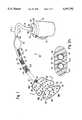
- FIG. 1is a perspective view of an embodiment of a therapeutic treatment device of the present invention having a fluid inlet line, a fluid outlet line, and a manual bulb pump positioned across the inlet line;
- FIG. 2Ais a cross-sectional elevational view of the sheath of FIG. 1 taken along line 2--2.
- FIG. 2Bis a cross-sectional elevational view of an alternate sheath.
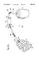
- FIG. 3is a perspective view of the pad of FIG. 1 conformably positioned on the knee of a user.
- FIG. 4is a cross-sectional elevational view of the pad of FIG. 1 taken along line 4--4.
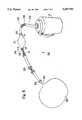
- FIG. 5is a perspective view of an alternate embodiment of a therapeutic treatment device of the present invention having a fluid inlet line, a fluid outlet line, and a motor-driven submersible pump positioned across the fluid inlet line;
- FIG. 6Ais a perspective view of another alternate embodiment of a therapeutic treatment device of the present invention having a single fluid flow line and a manual bulb pump positioned across the flow line;
- FIG. 6Bis a schematic representation of the therapeutic treatment device shown in FIG. 6A;
- FIG. 7Ais a cross-sectional elevational view of the manual bulb pump of FIG. 6 in the intake mode
- FIG. 7Bis a cross-sectional elevational view of the manual bulb pump of FIG. 6A in the discharge mode.
- FIG. 8is a perspective view of yet another alternate embodiment of a therapeutic treatment device of the present invention having a single fluid flow line and a manual bulb pump positioned across the flow line.
- the therapeutic treatment device of the present inventionis shown and generally designated as 10.
- the present therapeutic treatment device 10has a high temperature embodiment and a low temperature embodiment which are substantially identical in structure, differing only in the nonambient temperature of a treatment fluid circulated therethrough. Accordingly, the description of the therapeutic treatment device 10 as shown and set forth below applies generally to both the high and low temperature embodiments.
- the therapeutic treatment device 10comprises a pliant fluid-retaining heat transfer element in the form of a hollow pad 12, a fluid reservoir 14, and a unitary tubular sheath 16 enclosing a pair of fluid lines extending between the pad 12 and the fluid reservoir 14. A portion of the sheath 16 is cut away in FIG. 1 for purposes of illustration exposing the fluid lines 18, 20 enclosed by the sheath 16.
- the therapeutic treatment device 10further comprises a pump 22 for driving a treatment fluid between the pad 12 and the fluid reservoir 14 via the fluid lines 18, 20.
- the pump 22is a compressible, elastomeric bulb having good memory characteristics enabling the bulb pump 22 to be elastically deformed by compression, yet return to its original shape following compression as will be described hereafter.
- the bulb pump 22is positioned in-line across the inlet line 18 at an intermediate point in the line 18 relatively distal to both the pad 12 and the fluid reservoir 14.
- the bulb pump 22is provided with a pump inlet port 24 and a pump outlet port 26 enabling fluid communication between the interior chamber of the bulb pump 22, the pad 12 and the fluid reservoir 14 via the inlet line 18.
- Fluid reservoir 14is remotely positioned relative to the pad 12 and bulb pump 22 at the reservoir end 28 of the tubular sheath 16 and the associated fluid inlet and outlet lines 18, 20.
- Fluid reservoirs having present utilitycan be substantially any fluid container, although the preferred fluid reservoir 14, as shown herein, is a well-insulated passive vessel with impeded heat transfer between the fluid and the external environment across the vessel walls. As a passive vessel, the fluid reservoir 14 requires no active heating or cooling element to maintain the nonambient temperature of the treatment fluid therein.
- the fluid reservoir 14 shown hereinis a conventional heat-insulative water jug having a removable lid 30 and a handle 32 for ease of carrying.
- the lid 30is removed from the reservoir 14 when it is desired to replace the treatment fluid, but the lid 30 is retained in place on the reservoir 14 during operation of the therapeutic treatment device 10 to maintain the nonambient temperature of the treatment fluid.
- An opening 34is formed through the lid 30, enabling the reservoir end 28 of the fluid lines 18, 20 to fluid communicate with the reservoir 14 across a fitting 36 when the lid 30 is in place.
- a relatively small vent opening 38is also formed through the lid 30 to vent the interior of the reservoir 14 to the atmosphere.
- the reservoir 14retains an excess of the nonambient temperature treatment fluid exceeding the capacity of the pad 12 and fluid lines 18, 20.
- the treatment fluidis a fluid cooled below ambient room temperature, such as ice water.
- the treatment fluidis a fluid heated above ambient room temperature, such as hot water.
- the unitary tubular sheath 16is shown to be an extended length of tubular material having a first longitudinal bore formed therethrough which is the fluid inlet line 18 providing fluid communication between the pad 12 and the reservoir 14 in the direction of the pad 12.
- the sheath 16further has a second longitudinal bore formed therethrough which is the fluid outlet line 20 providing fluid communication between the pad 12 and the reservoir 14 in the direction of the reservoir 14.
- the sheath 16is substantially continuous along the length of the fluid flowpath between the pad 12 and the fluid reservoir 14, being interrupted only by in-line components of the device 10, such as the bulb pump 22 and a selectively releasable joint 40 positioned across the inlet and outlet lines 18, 20 in a manner described hereafter.
- the sheath 16integrates the inlet and outlet lines 18, 20 into a single unitary structure that defeats kinking, tangling or other similar disruptions of the lines 18, 20, thereby facilitating uninterrupted operation of the therapeutic treatment device 10.
- the tubular sheath 16is formed from an elastic, resilient, heat-insulative foam that resists such kinking or tangling of the flow lines 18, 20.
- the sheath 16has an axial heat-insulative wall 41a having relatively low heat transfer properties positioned between the inlet line 18 and the outlet line 20 impeding heat exchange between the lines 18, 20.
- the sheathfurther has a radial heat-insulative wall 41b positioned between the external environment and each of the flow lines 18, 20 impeding heat exchange therebetween.
- the inlet line 18has an inlet liner tube 42 fitted therein and extending coaxially therethrough.
- the inlet liner tube 42is formed from a solid (i.e., non-foam), high-strength, flexible, substantially fluid-impermeable material, such as polyurethane, having an outside diameter about equal to the inside diameter of the inlet line 18.
- the outside diameter of the inlet liner tube 42is typically about 5/16 inches and the inside diameter of the inlet liner tube 42 is typically about 3/16 inches.
- the outlet line 20likewise has an outlet liner tube 44 fitted therein that is substantially identical to the inlet liner tube 30.
- the liner tubes 42, 44prevent leakage of treatment fluid from the inlet line 18 or outlet line 20 into the sheath 16 or the external environment when treatment fluid is present in the lines 18, 20.
- the liner tubes 42, 44also facilitate leak-proof connection and fluid communication between the inlet and outlet lines 18, 20 and the in-line components of the therapeutic treatment device 10, including the pad 12, the fluid reservoir 14, the bulb pump 22 and the releasable joint 40.
- the sheath 16further functions to prevent condensate formation on the exterior of the liner tubes 42, 44 when the nonambient temperature treatment fluid is contained therein.
- an alternate unitary tubular sheath 16'comprising an axial wall 41a' and a radial wall 41b'.
- the sheath 16'is similar to the sheath 16 of FIG. 2A except that the sheath 16' is formed from a material having substantially the same properties as the liner tubes 42, 44 described above. Accordingly, liner tubes are not utilized in the sheath 16'.
- the material of the sheath 16'is preferably a heat-conductive material having high heat transfer properties relative to the material of the sheath 16.
- the axial wall 41a' of the sheath 16'is relatively thin, thereby facilitating heat exchange between the treatment fluid in the inlet line 18' and the treatment fluid in the outlet line 20' enclosed by the sheath 16'.
- Heat exchange between the inlet and outlet lines 18', 20'reduces the temperature difference between the fresh treatment fluid entering the pad 12 and the spent treatment fluid exiting the pad 12 to lessen the trauma to the user caused by extreme temperature differences within the pad 12.
- the sheath 16'is enclosed within a jacket 41c' of heat-insulative material having substantially the same properties as the sheath 16 described above to impede heat exchange between the external environment and each of the flow lines 18', 20' and further to prevent condensate formation on the exterior of the sheath 16'.
- the pad 12is shown to be remotely positioned relative to the fluid reservoir 14 at the pad end 46 of the sheath 16 and associated fluid inlet and outlet lines 18, 20 opposite the reservoir end 28 thereof.
- the pad 12serves as the heat transfer element having a planar, pliant or flexible construction that is readily conformable to the contours of the external skin surface of the user.
- the planar pad 12is characterized as having three dimensions, but wherein the thickness of the pad 12 is very small relative to the length and width of the pad 12.
- the planar pad 12is additionally characterized as capable of being spread out flat in a resting position as shown in FIG.
- Padshaving substantially the same construction and configuration as the pad 12 of FIG. 1, are disclosed in U.S. patent application Ser. Nos. 08/069,195 and 08/172,022, both of which are incorporated herein by reference.
- the pad 12is shown to have a laminar construction, including an upper sheet 48a overlying a lower sheet 48b. Both sheets 48a, 48b are formed from a thin flexible heat-conductive material, such as transparent polyurethane.
- the outer face of the lower sheet 48bis exposed to engage the external skin surface when the pad 12 is operatively positioned on the body of a user.
- the outer face of the upper sheet 48ais bonded to a relatively thicker heat-insulative sheet 50 of a flexible foam material to prevent either heat loss through the upper sheet 48a to the surrounding environment, or heat gain through the upper sheet 48a from the surrounding environment.
- the heat-insulative sheet 50also reduces fluid condensation on the outside of the pad 12.
- a plurality of circular welds 56bond the sheets 48a, 48b together at periodic points across the pad 12.
- the circular welds 56function to divert fluid flow in a tortuous manner through the pad flowpath 54.
- the circular welds 56also function to limit the height and correspondingly the volume of the pad flowpath 54 when operating under elevated pressure.
- a plurality of linear weldsalso bond the sheets 48a, 48b together across the pad to delineate the pad flowpath 54.
- First and second linear welds 58a, 58bare aligned end to end along the longitudinal axis of the pad 12, separated at their ends by a narrow breach 60.
- the breach 60enables a limited degree of cross flow within the pad flowpath 54, thereby improving temperature distribution across the pad 12 during operation, and enabling continued operation should kinks occur in the pad 12. Additional delineation of the pad flowpath 54 is provided by orthogonally or diagonally oriented linear welds 62 extending from the ends of the first and second linear welds 58a, 58b.
- the pad 12is further provided with a pad inlet port 64 through the seam 52 slightly offset to one side of the first linear flow divider 58a.
- a pad outlet port 66is similarly provided in the seam 52 substantially adjacent to the pad inlet port 64, but slightly offset to the opposite side of the first linear flow divider 58a.
- the inlet and outlet liner tubes 42, 44 at the pad end 46 of the fluid lines 18, 20penetrate the pad flowpath 54 through the pad inlet and outlet ports 64, 66, respectively, to provide fluid communication between the pad flowpath 20 and the exterior of the pad 12.
- the inlet and outlet liner tubes 42, 44are sealingly bonded to the sheets 48a, 48b proximal to the pad inlet and outlet ports 64, 66, respectively, to prevent fluid leakage from the inlet and outlet lines 18, 20.
- a plurality of cut-outs 68are formed in the periphery of the pad 12 to facilitate conformance of the pad 12 to the external skin surface of the body.
- the pad 12is shown conformed to the convex external skin surface of the knee joint 70.
- the pad 12overlies the knee joint 70 with the lower sheet 48b contacting the external skin surface of the joint 70 and with the heat-insulative sheet 50 exposed to the environment.
- the cut-outs 68enable the user to arrange the planar pad 12 in a configuration that substantially close-fittingly encloses the convex knee joint 70 without substantially kinking the pad flowpath 54.
- the pad 12can alternatively be conformed to other external skin surfaces of the body in a like manner, and in particular to other substantially convex contoured external skin surfaces such as the shoulder, elbow, and hip. It is further apparent that although the therapeutic treatment device 10 is shown and described with reference to a single pad configuration, the present invention is not limited to any one specific pad configuration. Other planar pliant pads fall within the scope of the present invention, such as disclosed in U.S. Pat. Nos. Des. 345,609; and Des. 348,106; and in U.S. patent application Ser. Nos. 29/002,338; and 29/002,333, all incorporated herein by reference.
- the releasable joint 40is provided in the fluid lines 18, 20 between the pad 12 and bulb pump 22 relatively proximal to the pad 12 to enable selective dissociation of the pad 12 from the therapeutic treatment device 10 during periods of inoperation, thereby facilitating interchangeability or removal of the pad 12 for storage or cleaning.
- the joint 40 shown hereinis of the type disclosed in U.S. Pat. No. 5,232,020, incorporated herein by reference, having two snap-action locking couplings 72a, 72b with lock release buttons. As described in U.S. Pat. No. 5,232,020, but not shown herein, each coupling comprises an internal male connector on the reservoir side and an internal female connector on the pad side of the coupling, or vice versa.
- the internal male connectorsare housed together in a unitary molded mount, and the internal female connectors are similarly housed together in a unitary molded mount to facilitate simultaneous connection of the couplings.
- External male connectorsare press fitted into the sheath 16 and associated inlet and outlet lines 18, 20.
- the couplings 72a, 72bare further provided with internal shut off valves which automatically close fluid lines 18, 20 when the couplings 72a, 72b are disconnected.
- the releasable joint 40can be excluded from the fluid lines 18, 20 of the therapeutic treatment device 10, so that the pad 12 remains fixedly connected to the fluid lines 18, 20 for the life of the device.
- the resulting jointless therapeutic treatment deviceis substantially identical to the jointed therapeutic treatment device of FIG. 1. Omission of the releasable joint 40 from the therapeutic treatment device does not defeat the closed circulatory character of the system flowpath, nor substantially modify the remaining structure or functional operation of the jointless therapeutic treatment device as compared to the therapeutic treatment device 10 having a releasable joint 40.
- the therapeutic treatment device 10 of FIG. 1further comprises a flow restriction positioned in the system flowpath downstream of the pad flowpath 54 (obscured from view in FIG. 1 by the sheath 16).
- the flow restrictionis positioned in the pad outlet port 66 or the outlet line 20 to provide a fluid backpressure in the pad flowpath 54.
- the fluid backpressureimpedes the flow of treatment fluid back to the reservoir 14 via the pad outlet port 66 and outlet line 20, thereby desirably inflating the pad 12 with pressurized treatment fluid.
- the flow restrictioncan be substantially any element that diminishes the cross-sectional area of the downstream system flowpath.
- the flow restrictioncan have a fixed reduced cross-section, such as an in-line orifice, a crimp, or reduced-size tubing, or can have a variable reduced cross-section, such as a check valve or a selectively adjustable valve.
- a preferred flow restrictionis a conventional pressure relief valve positioned in the outlet line 20 proximal to the pad outlet port 66. The valve remains closed until a preset relief pressure is exceeded in the pad flowpath 54.
- the relief pressurecan be preset to any pressure above the ambient atmospheric pressure, but is typically preset at about 1 psi greater than the ambient atmospheric pressure.
- Each of the above-recited embodiments of the therapeutic treatment deviceis operated in substantially the same manner as described hereafter. Operation is initiated by filling the fluid reservoir 14 with a fresh nonambient temperature treatment fluid and securing the lid 30 to passively maintain the nonambient temperature of the treatment fluid therein.
- the pad 12is positioned on the desired treatment region of the body and the inlet and outlet lines 18, 20 and intervening pad flowpath 54 are placed in fluid communication with the fluid reservoir 14.
- the pad flowpath 54is charged with fresh treatment fluid by first charging the interior chamber of the bulb pump 22. Charging of the bulb pump 22 is effectuated by sequentially compressing the bulb pump 22 and then allowing it to elastically expand back to its original memorized shape. Expansion of the bulb pump 22 draws fresh nonambient temperature treatment fluid through the inlet line 18 across a conventional check valve (not shown), such as a ball valve, positioned at the pump inlet port 24.
- the pump inlet valvepermits fluid flow from the reservoir 14 in the direction of the pump 22, but prevents fluid flow from the pump 22 in the direction of the reservoir 14.
- another conventional check valveshown herein as a ball valve 74 positioned at the pump outlet port 26, permits fluid flow through the inlet line 18 in the direction of the pad 12, but prevents fluid flow from the pad 12 in the direction of the pump 22.
- a transparent window 76is provided in the sheath 16 that is formed from a clear rigid plastic or glass enabling the user to view operation of the pump outlet valve 74 and the flow of the treatment fluid therethrough.
- the treatment fluidis transferred to the pad flowpath 54 by manually compressing the bulb pump 22, thereby driving the fresh treatment fluid across the pump outlet valve through the inlet line 18 into the pad flowpath 54.
- the force of the treatment fluid as the bulb pump 22 is compressedalso closes the pump inlet valve preventing any fresh fluid from returning to the reservoir 14 via the pump inlet port 24. This procedure is repeated as often as necessary until the pad flowpath 54 is completely filled with fresh treatment fluid at a pressure up to the preset pressure of the pressure relief valve.
- the treatment fluid residing in the pad flowpath 54thermally equilibrates toward the ambient temperature of the external environment, diminishing the effectiveness of the treatment.
- the treatment fluid in the pad flowpath 54is deemed spent when it thermally equilibrates to a predetermined temperature approaching the ambient temperature, at which time the spent treatment fluid is desirably replaced with fresh nonambient temperature treatment fluid from the reservoir 14.
- the spent treatment fluidis replaced by substantially repeating the above-described procedure. Because the pad flowpath 54 is filled with spent treatment fluid, however, the fresh treatment fluid must be transferred from the bulb pump 22 into the pad flowpath 54 with a sufficient displacement force to open the pressure relief valve in the outlet line 20 and drive the spent treatment fluid from the pad flowpath 54 back to the reservoir 14 via the outlet line 20. In the reservoir 14, the spent treatment fluid is diluted by the greater volume of fresh treatment fluid, thereby restoring the spent treatment fluid to an effective nonambient treatment temperature for future circulation back into the pad flowpath 54. This treatment fluid circulation cycle can be repeated at periodic time intervals thereafter as often as desired for effective treatment of the body.
- FIG. 5another embodiment of a therapeutic treatment device is shown and generally designated 100.
- Identical reference charactersare used to identify elements common to both the therapeutic treatment device 100 and the therapeutic treatment device 10.
- the device 100replaces the in-line, manual bulb pump 22 of the device 10 with an in-line, electrically-powered, motor-driven submersible pump 102 positioned at the reservoir end 28 of the inlet and outlet lines 18, 20.
- the submersible pump 102is preferably a conventional, single-speed impeller pump having a substantially constant output.
- the therapeutic treatment device 100also provides a control unit 104 proximal to the position occupied by the bulb pump 22 in the device 10.
- the control unit 104is integral with the sheath 16 and has a rigid housing 106 with a manually adjustable valve control knob 108, a temperature display 110, and an electrical connector 112 mounted thereon.
- the control knob 108engages a conventional adjustable flow restrictor valve (not shown) positioned in the outlet line 20 at the location of the control unit 104 for manual adjustment of the valve in a manner described hereafter.
- the temperature display 110in association with a temperature measuring means positioned in the outlet line 20, provides a visual readout of the fluid temperature therein.
- the temperature display 110 and measuring meansare preferably integrally embodied within a conventional liquid thermometer.
- the electrical connector 112is a disconnectable power cord and transformer assembly enabling electrical communication between the submersible pump 102 and an external power source, such as a conventional ac wall plug 114. Electrical power is conducted from the electrical connector 112 to the pump 102 via an internal power line 116 extending through the sheath 16 in parallel with the inlet and outlet lines 18, 20.
- the device 100can be provided with an internal power pack (not shown) in the control unit 104 which conducts electrical power to the pump 102 via the internal power line 116, thereby eliminating the electrical connector 112 from the device 100.
- the fluid reservoir 118 of the therapeutic treatment device 100is similar to the fluid reservoir 14 of the device 10 except that the present reservoir 118 is modified with a substantially larger opening 120 to receive the submersible pump 102 and the reservoir end 28 of the sheath 16. Accordingly, the fluid reservoir 118 is a wide-mouth heat-insulative container, such as a conventional insulated picnic cooler.
- the fluid reservoir 118has a cover 122 positioned over the opening 120 for passively maintaining the nonambient temperature of the treatment fluid therein and has a slot 124 formed at the opening 120 that permits the sheath 16 to extend into the reservoir 118 when covered.
- the pad 126 of the therapeutic treatment device 100is configured nearly identically to the pad 12 of the device 10 except that the circular welds 128 of the pad 126 are spaced closer together to decrease the height and correspondingly the volume of the pad flowpath 130. Because the treatment fluid of the device 100 is continuously circulated through the pad flowpath 130, the treatment fluid in the pad flowpath 130 does not readily equilibrate to the ambient temperature of the external environment and, therefore, less treatment fluid is required to maintain the desired nonambient temperature at the body surface.
- the therapeutic treatment device 100is substantially the same as the therapeutic treatment device 10 in all other respects, having a sheath 16, an inlet line 18, an outlet line 20, and a releasable joint 40, all of similar construction.
- the fluid reservoir 118is initially filled with a fresh low-temperature therapeutic treatment fluid such as ice water.
- the submersible pump 102is submersed in the treatment fluid with the sheath 16 extending from the reservoir 118, thereby maintaining the inlet and outlet lines 18, 20 and intervening pad flowpath 130 in fluid communication with the treatment fluid in the reservoir 118.
- the cover 122is secured to the reservoir 118 and the pad 126 is positioned on the desired treatment region of the body.
- the pump 102is electrically activated to continuously circulate the treatment fluid through the pad flowpath 130 by cycling the fluid from the fluid reservoir 118 via the inlet line 18, through the pad flowpath 130, and back to the fluid reservoir 118 via the outlet line 20.
- the fluid circulation cycleis performed continuously at a substantially constant pump output for the duration of the desired treatment period.
- Temperature control of the pad 126 during the circulation cycleis achieved by regulating the flow rate of treatment fluid through the pad flowpath 130.
- the userregulates the flow rate of the treatment fluid by moving the control knob 108 to correspondingly adjust the cross-sectional area of the flowpath across the flow restrictor valve positioned in the outlet line 20 while the pump 102 operates continuously at a constant output indicated by the speed and pumping pressure of the pump. If the control knob 108 is moved to reduce the cross-sectional area of the flow restrictor valve, the temperature of the pad 126 is increased. Conversely, if the control knob 108 is moved to increase the cross-sectional area of the flow restrictor valve, the temperature of the pad 126 is decreased.
- Temperature controlis facilitated by monitoring the temperature of the treatment fluid in the outlet line 20 using the temperature display 110 on the control unit 104. It is further noted that the adjustable flow restrictor valve acts to regulate the backpressure in the pad flowpath 130 as a function of the cross-sectional area of the valve flowpath.
- the high temperature embodiment of the device 100is primarily distinguishable from the low temperature embodiment described above in that a heated fluid is substituted for ice water.
- the heated fluidis preferably water which is heated to a temperature exceeding the ambient temperature of the surrounding environment.
- the temperature of the pad 126is decreased by partially closing the adjustable flow restrictor valve in the outlet line 20 to diminish flow rate of heated fluid therethrough, while the temperature of the pad 126 is increased by opening the adjustable flow restrictor valve to increase the flow rate of heated fluid therethrough.
- a therapeutic treatment devicecan be provided within the scope of the present invention that is substantially the same as the device 10, wherein the flow rate of nonambient temperature treatment fluid through the pad flowpath is regulated by replacing the fixed-output pump with a variable-output pump having an adjustable output control mechanism and eliminating the adjustable flow restrictor valve in the outlet line.
- the flow rate of the fluid through the pad flowpathis regulated to control the temperature of the pad in an equivalent manner by moving a power control knob on the pump to correspondingly adjust the pump.
- the pump outputis increased. Conversely, if it is desired to raise the temperature of the pad in the low temperature embodiment of the device, the pump output is decreased.
- alternate meanscan be placed in the outlet line to obtain a desired backpressure in the pad flowpath, such as an in-line orifice, a crimp, reduced-size tubing, or a check valve.
- a further embodiment of a therapeutic treatment deviceis shown and generally designated 200.
- Identical reference charactersare used to identify elements common to both the therapeutic treatment device 200 and the therapeutic treatment device 10.
- the device 200is substantially the same as the device 10, but the device 200 has only one fluid flow line 202 providing a single fluid pathway between the pad 12 and the fluid reservoir 14 to alternately supply fresh nonambient temperature fluid to the pad flowpath 54 from the fluid reservoir 14 via the pad inlet port 64 and return spent treatment fluid to the fluid reservoir 14 from the pad flowpath 54 via the pad outlet port 66.
- the flow line 202is a single longitudinal bore extending through a heat-insulative sheath 204 having a liner tube 206 retained therein in substantially the same manner as described above with respect to the device 10 and the sheath 16.
- the sheath 204also has a releasable joint 208 positioned proximal to the pad 12 in a manner similar to the device 10 and the joint 40.
- the present therapeutic treatment device 200has a pump assembly positioned in the flow line 202 between the pad 12 and the fluid reservoir 14.
- the pump assemblyincludes a bulb pump 22 having an inlet port 24 and an outlet port 26, and further includes an inlet leak-back valve positioned at the pump inlet port 24 and an outlet leak-back valve positioned at the pump outlet port 26.
- the leak-back valvesselectively permit substantially unrestricted flow of treatment fluid at a full flow rate in the direction of the pad flowpath 54, while continuously permitting restricted flow of treatment fluid in the direction of the fluid reservoir 14 at a substantially reduced flow rate.
- the pump assemblyis described in greater detail hereafter with reference to FIGS. 7A and 7B.
- the pump assemblycomprises the bulb pump 22 having a hollow interior fluid chamber 210 in fluid communication with the exterior of the bulb pump 22 via the pump inlet and outlet ports 24, 26.
- the pump assemblyfurther comprises the inlet leak-back valve integrally contained within an inlet valve housing 212 and the outlet leak-back valve integrally contained within an outlet valve housing 214.
- the inlet and outlet valve housings 212, 214are formed from a rigid material, such as a rigid plastic.
- the inlet valve housing 212has an inlet valve chamber 216, an inlet valve seat 218, ball retention vanes 220, an inlet leak-back channel 222, an inlet internal male end 224, and an inlet external male end 226.
- a ball 228functioning as a valve plunger.
- the inlet leak-back channel 222is a very narrow passageway relative to the inlet valve chamber 216 providing limited fluid communication across the inlet leak-back valve when the valve is in the closed position with the ball 228 against the inlet valve seat 218 as described hereafter.
- Fluid-tight connection of the bulb pump 22 to the flow line 202is provided in part by receiving the inlet internal male end 224 of the inlet valve housing 212 within the pump inlet port 24 and receiving the inlet external male end 226 within the liner tube 206.
- the outlet valve housing 214has an outlet valve chamber 230, an outlet valve seat 232, an outlet leak-back channel 234, an outlet internal male end 236, and an outlet external male end 238.
- a spring 240 and a flow indicator ball 242are displacably retained within the outlet valve chamber 230 and the transparent flow window 76 is integral with the outlet valve housing 214 enabling the user to observe operation of the spring 240 and ball 242 retained therein.
- the outlet leak-back channel 234is a very narrow passageway relative to the outlet valve chamber 230 providing limited fluid communication across the outlet leak-back valve when the valve is in the closed position with the ball 242 against the outlet valve seat 232 as described hereafter. It is noted that the inlet and outlet valves of the device 10 can be configured substantially identically to the inlet and outlet leak-back valves of the device 200 absent the leak-back channels 222, 234.
- Fluid-tight connection of the bulb pump 22 to the flow line 202is further provided by receiving the outlet internal male end 236 of the outlet valve housing 214 within the pump outlet port 26 and receiving the outlet external male end 238 within the liner tube 206.
- the flow indicator ball 242functions both as a displacable valve plunger and as a flow indicator for the treatment fluid.
- the ball 242preferably has a distinctively visible color, such as red, to enhance its visibility to the user when viewed through the transparent flow window 76.
- inlet and outlet leak-back valveshave been described above as having inlet and outlet leak-back channels 222, 234, respectively, enabling limited fluid communication across the leak-back valves when the valves are in the closed position. It is understood, however, that this function can be equivalently performed in the absence of the leak-back channels 222, 234 by providing small notches in the valve seats 218, 232 that permit limited fluid flow past the valve seats 218, 232 when the respective balls 228, 242 are seated therein.
- a plurality of additional in-line fittings and valvesenable selective supply or return of the nonambient treatment fluid between the pad flowpath 54 and the fluid reservoir 14 via the flow line 202 in cooperation with the inlet and outlet leak-back valves.
- a three-branched "Y" fitting 244joins the pad inlet and outlet ports 64, 66 with the flow line 202 at the pad end 246 of the line 202.
- a conventional one-way check valve(shown as 247a in FIG. 6B) is positioned in or near one branch of the "Y" fitting 244 at the pad inlet port 64 to selectively permit flow across the port 64 only in the direction of the pad flowpath 54 and not in the direction of the reservoir 14.
- a flow restrictionshown as 247b in FIG.
- FIG. 6Bschematically shows the relationship between the primary structural elements of the therapeutic treatment device 200.
- therapeutic treatment device 200is operated by filling the fluid reservoir 14 with a fresh nonambient temperature treatment fluid and positioning the pad 12 on the desired treatment region of the body in substantially the same manner as described above with respect to the therapeutic treatment device 10.
- the pad flowpath 54which is initially in a substantially evacuated condition, is charged with the fresh treatment fluid by first manually compressing the bulb pump 22 to evacuate the interior chamber 210. Thereafter, the bulb pump 22 is allowed to elastically expand in the direction of the arrows 248, as shown in accordance with the intake mode of FIG. 7A. As the bulb pump 22 expands, the fresh treatment fluid is drawn through the flow line 202 in the direction of the arrow 250, and urges the ball 228 against the retention vanes 220.
- the fresh treatment fluidis permitted to enter the interior chamber 210 via the pump inlet port 24.
- the flow indicator ball 242is biased against the outlet valve seat 232 by the force of the spring 240, substantially impeding significant amounts of fluid from entering the interior chamber 210 via the pump outlet port 26.
- the bulb pump 22When the bulb pump 22 is fully expanded with the fresh treatment fluid, it is manually compressed in the direction of the arrows 252, as shown in accordance with the discharge mode of FIG. 7B.
- the degree of compression force that the user applies to the bulb pump 22is regulated by the user in correspondence with the position of the flow indicator ball 42 and spring 240, as observed through the transparent flow display section 76.
- the bulb pump 22For an optimal flow rate and fluid pressure in the flow line 202, the bulb pump 22 is compressed with a force that maintains the flow indicator ball 242 at a position about midway within the flow display section 76 as shown in FIG. 7B.
- the fresh treatment fluidis driven from the interior chamber 210 toward the pump outlet port 26.
- the force of the fresh treatment fluiddisplaces the flow indicator ball 242 away from the outlet valve seat 232 by compressing the spring 240 and permits the fresh treatment fluid to exit the interior chamber 210 via the pump outlet port 26 in the direction designated by the arrow 254.
- the fresh treatment fluidtravels the remaining length of the flow line 202 and the bulk, if not all, of the fresh treatment fluid is diverted by the flow restriction 247b at the pad outlet port 66 into the pad inlet port 64.
- the fluid pressureurges the check valve 247a at the pad inlet port 64 open permitting the fresh treatment fluid to enter the pad flowpath 54.
- the force of the treatment fluid as the bulb pump 22 is compressedalso urges the ball 228 against the inlet valve seat 218 substantially impeding significant amounts of fresh fluid from returning to the reservoir 14 via the pump inlet port 24. This procedure is repeated as often as necessary until the pad flowpath 54 is substantially filled with fresh treatment fluid.
- a reversible pumpis substituted for the compressible bulb pump 22 in the fluid flow line 202.
- the reversible pumpis a manual or motor-driven pump, such as a rotary impeller pump, for selectively driving fluid through the fluid flow line 202 in the direction of the pad flowpath 54 or the fluid reservoir 14.
- the alternate embodimenthas a pair of one-way valves positioned at the pad inlet and outlet ports 64, 66 respectively, but obviates the leak-back valves at the pump inlet and outlet ports 24, 26.
- FIG. 8another embodiment of a therapeutic treatment device is shown and generally designated 300.
- Identical reference charactersare used to identify elements common to the therapeutic treatment device 300 and the therapeutic treatment device 200.
- the device 300is substantially the same as the device 200, but a relatively larger volume bladder 302 having a single port 304 in fluid communication with the fluid flow line 202 is substituted for the pad 12 of the device 200 having separate inlet and outlet ports 64, 66.
- the bladder 302has a three-dimensional configuration with a pliant heat transfer surface that is conformable to the contours of the external skin surface of the user.
- the bladder 302is distinguishable from a planar pad insofar as the bladder 302 has a significant thickness relative to the length and width of the bladder 302.
- a straight coupling 306joins the fluid flow line 202 with the port 304.
- the coupling 306is substantially free of any flow restrictions or valves.
- a compressible bulb pump 22 having leak-back valves at the pump inlet and outlet ports 24, 26is shown positioned in the fluid flow line 202, it is within the scope of the present invention to substitute substantially any other manual or motor-driven pump enabling fluid leak-back across the pump for the bulb pump 22.
- the therapeutic treatment device 300is operated by charging a relatively large volume of fresh treatment fluid to the bladder 302 from the fluid reservoir 14 by means of the pump 22 via the fluid flow line 202 and the port 304.
- the pumping pressurepressurizes the treatment fluid in the bladder 302 to a fluid pressure exceeding the ambient pressure. Once pumping ceases, however, no further pumping pressure is exerted on the treatment fluid in the bladder 302.
- the elevated fluid pressure in the bladder 302consequently drives spent treatment fluid back to the fluid reservoir 14 across the leak-back valves at a restricted flow rate.
- the restricted flow rateis sufficiently slow that the volume of treatment fluid in the bladder 302 at any given time is adequate to provide therapeutic treatment to the body for an extended period of time.
- pumpingis resumed to charge fresh treatment fluid to the bladder 302.
- the fresh treatment fluid pumped into the bladder 302mixes with the residual treatment fluid remaining in the bladder 302 and the mixture equilibrates to an acceptable nonambient temperature enabling continued therapeutic treatment of the body.
Landscapes
- Health & Medical Sciences (AREA)
- Animal Behavior & Ethology (AREA)
- Public Health (AREA)
- Engineering & Computer Science (AREA)
- Biomedical Technology (AREA)
- Heart & Thoracic Surgery (AREA)
- Vascular Medicine (AREA)
- Veterinary Medicine (AREA)
- Life Sciences & Earth Sciences (AREA)
- General Health & Medical Sciences (AREA)
- Physics & Mathematics (AREA)
- Thermal Sciences (AREA)
- Nursing (AREA)
- Orthopedic Medicine & Surgery (AREA)
- Anesthesiology (AREA)
- Hematology (AREA)
- Thermotherapy And Cooling Therapy Devices (AREA)
Abstract
Description
______________________________________ Serial Number Filing Date ______________________________________ 07/850,071 March 12, 1992 08/100,047 July 30, 1993 08/199,333 February 22, 1994 ______________________________________
Claims (12)
Priority Applications (1)
| Application Number | Priority Date | Filing Date | Title |
|---|---|---|---|
| US08/273,020US5507792A (en) | 1990-09-05 | 1994-07-08 | Therapeutic treatment device having a heat transfer element and a pump for circulating a treatment fluid therethrough |
Applications Claiming Priority (10)
| Application Number | Priority Date | Filing Date | Title |
|---|---|---|---|
| US07/578,508US5080089A (en) | 1990-09-05 | 1990-09-05 | Therapeutic apparatus applying compression and a nonambient temperature fluid |
| US07767494US5241951B1 (en) | 1990-09-05 | 1991-09-30 | Therapeutic nonambient temperature fluid circulation system |
| US85134592A | 1992-03-12 | 1992-03-12 | |
| US85007192A | 1992-03-12 | 1992-03-12 | |
| US07/906,407US5324319A (en) | 1990-09-05 | 1992-07-01 | Gravity driven therapeutic fluid circulation device |
| US6919593A | 1993-05-27 | 1993-05-27 | |
| US08100047US5330519B1 (en) | 1990-09-05 | 1993-07-30 | Therapeutic nonambient temperature fluid circulation system |
| US08/172,022US5662695A (en) | 1990-09-05 | 1993-12-21 | Occlusion-resistant fluid pad conformable to a body for therapeutic treatment thereof |
| US19933394A | 1994-02-22 | 1994-02-22 | |
| US08/273,020US5507792A (en) | 1990-09-05 | 1994-07-08 | Therapeutic treatment device having a heat transfer element and a pump for circulating a treatment fluid therethrough |
Related Parent Applications (3)
| Application Number | Title | Priority Date | Filing Date |
|---|---|---|---|
| US85007192AContinuation-In-Part | 1990-09-05 | 1992-03-12 | |
| US08100047Continuation-In-PartUS5330519B1 (en) | 1990-09-05 | 1993-07-30 | Therapeutic nonambient temperature fluid circulation system |
| US19933394AContinuation-In-Part | 1990-09-05 | 1994-02-22 |
Publications (1)
| Publication Number | Publication Date |
|---|---|
| US5507792Atrue US5507792A (en) | 1996-04-16 |
Family
ID=27578321
Family Applications (1)
| Application Number | Title | Priority Date | Filing Date |
|---|---|---|---|
| US08/273,020Expired - LifetimeUS5507792A (en) | 1990-09-05 | 1994-07-08 | Therapeutic treatment device having a heat transfer element and a pump for circulating a treatment fluid therethrough |
Country Status (1)
| Country | Link |
|---|---|
| US (1) | US5507792A (en) |
Cited By (131)
| Publication number | Priority date | Publication date | Assignee | Title |
|---|---|---|---|---|
| US5888185A (en)* | 1997-06-06 | 1999-03-30 | Sports Prescriptions, Inc. | Equine therapeutic device |
| US6086609A (en)* | 1997-12-08 | 2000-07-11 | Jay R. Buckley | Controlled cold therapy apparatus |
| US6117164A (en) | 1997-06-06 | 2000-09-12 | Dj Orthopedics, Llc | Flexible multijoint therapeutic pads |
| US6238427B1 (en) | 1999-03-30 | 2001-05-29 | John G. Matta | Therapeutic heat transfer pads |
| US6279338B1 (en)* | 2000-02-19 | 2001-08-28 | Samir Badry Mohamed | Cold compresses apparatus |
| US6312453B1 (en) | 1998-07-16 | 2001-11-06 | Olympic Medical Corp. | Device for cooling infant's brain |
| US6419691B1 (en)* | 2000-03-23 | 2002-07-16 | Milene H. Hanner | Thermal energy therapy |
| US20020183718A1 (en)* | 2001-05-30 | 2002-12-05 | Morton Kevin B. | Disposable fluid loop for intraductal fluid aspiration system |
| WO2002087414A3 (en)* | 2001-04-30 | 2003-04-03 | Medivance Inc | Localized bodily cooling/heating apparatus and method |
| US20030073951A1 (en)* | 2001-05-30 | 2003-04-17 | Morton Kevin B. | Disposable patient interface for intraductal fluid aspiration system |
| USD487147S1 (en) | 2002-08-08 | 2004-02-24 | Medivance Incorporated | Male connector in a patient temperature control system |
| USD487148S1 (en) | 2002-08-08 | 2004-02-24 | Medivance Incorporated | Male connector in a patient temperature control system |
| US20040068310A1 (en)* | 2002-10-08 | 2004-04-08 | Howard Edelman | Therapy pad |
| US6736836B2 (en) | 2000-02-17 | 2004-05-18 | The Johns Hopkins University | Transplant organ external cooling system |
| US6740110B2 (en) | 2001-05-22 | 2004-05-25 | David A. Babcock | Method and devices of inflammation control, and therapy |
| USD492773S1 (en) | 2002-08-08 | 2004-07-06 | Medivance Incorporated | Female connector in a patient temperature control system |
| US20040158303A1 (en)* | 2002-04-29 | 2004-08-12 | Medcool, Inc. | Method and device for rapidly inducing and then maintaining hypothermia |
| US6802855B2 (en) | 2002-08-08 | 2004-10-12 | Medivance Incorporated | Patient temperature control system connector apparatus |
| US20040210176A1 (en)* | 2003-01-06 | 2004-10-21 | Richard Diana | Method and device for treatment of edema |
| US20040225341A1 (en)* | 2002-07-11 | 2004-11-11 | Life Recovery Systems, Inc. | Apparatus for altering the body temperature of a patient |
| US6827728B2 (en) | 2002-08-08 | 2004-12-07 | Medivance Incorporated | Patient temperature control system |
| US20040249427A1 (en)* | 2003-06-06 | 2004-12-09 | Yunes Nabilsi | Medical cooler device |
| USD500140S1 (en) | 2003-08-29 | 2004-12-21 | Dj Orthopedics, Llc | Thermal therapy pad |
| US20050096714A1 (en)* | 2002-07-11 | 2005-05-05 | Freedman Robert J.Jr. | Apparatus for altering the body temperature of a patient |
| USD505727S1 (en) | 2003-08-29 | 2005-05-31 | Dj Orthopedics, Llc | Thermal therapy pad |
| US20050137506A1 (en)* | 2003-12-23 | 2005-06-23 | Loyal Chow | Passive exercise apparatus |
| US20050143797A1 (en)* | 2003-07-18 | 2005-06-30 | Thermotek, Inc. | Compression sequenced thermal therapy system |
| USD510626S1 (en) | 2003-08-29 | 2005-10-11 | Dj Orthopedics, Llc | Thermal therapy pad |
| US20060030915A1 (en)* | 2003-08-04 | 2006-02-09 | Medcool, Inc. | Method and apparatus for reducing body temperature of a subject |
| US7008445B2 (en) | 2002-04-29 | 2006-03-07 | Medcool, Inc. | Method and device for rapidly inducing hypothermia |
| US20060069418A1 (en)* | 2004-09-24 | 2006-03-30 | Schock Robert B | Apparatus for altering the body temperature of a patient |
| USD527108S1 (en) | 2003-10-10 | 2006-08-22 | Dj Orthopedics, Llc | Thermal therapy pad |
| USD532523S1 (en) | 2003-08-29 | 2006-11-21 | Dj Orthopedics, Llc | Thermal therapy pad |
| US20060282140A1 (en)* | 2002-07-11 | 2006-12-14 | Life Recovery Systems Hd, Llc | Apparatus for Altering the Body Temperature of a Patient |
| US20070112401A1 (en)* | 2005-10-14 | 2007-05-17 | Niran Balachandran | Critical care thermal therapy method and system |
| US20070118194A1 (en)* | 2005-11-22 | 2007-05-24 | Breg, Inc. | Non-ambient temperature therapy system with automatic treatment temperature maintenance |
| US20070282249A1 (en)* | 2006-05-09 | 2007-12-06 | Tony Quisenberry | Method of and system for thermally augmented wound care oxygenation |
| US20070293919A1 (en)* | 1998-08-24 | 2007-12-20 | Radiant Medical, Inc. | Disposable cassette for intravenous heat exchange catheter |
| US20080021531A1 (en)* | 2003-09-24 | 2008-01-24 | Kane John R | Methods and apparatus for increasing blood circulation |
| US20080071330A1 (en)* | 2006-05-09 | 2008-03-20 | Tony Quisenberry | Wound care method and system with one or both of vacuum-light therapy and thermally augmented oxygenation |
| US20080097561A1 (en)* | 2006-10-18 | 2008-04-24 | Medcool, Inc. | Dual cycle thermal system and method of use |
| US20080132816A1 (en)* | 2006-12-04 | 2008-06-05 | Kane John Roy | Methods and Apparatus for Adjusting Blood Circulation |
| US20080132976A1 (en)* | 2006-12-04 | 2008-06-05 | Kane John Roy | Methods and apparatus for adjusting blood circulation |
| US20080221493A1 (en)* | 2006-12-07 | 2008-09-11 | Life Recovery Systems Hd, Llc | Apparatus for altering the body temperature of a patient and administering decompression to the patients torso |
| US20080269852A1 (en)* | 2005-04-07 | 2008-10-30 | Medcool, Inc | Methods and Apparatus for Thermal Regulation of a Body |
| US20090109622A1 (en)* | 2004-08-12 | 2009-04-30 | Parish Overton L | Thermal control system for rack mounting |
| US20090177184A1 (en)* | 2008-01-09 | 2009-07-09 | Christensen Scott A | Method and apparatus for improving venous access |
| US20100030306A1 (en)* | 2002-10-08 | 2010-02-04 | Howard Edelman | Therapeutic Cranial Wrap for a Contrast Therapy System |
| US7658205B1 (en) | 2002-12-19 | 2010-02-09 | Vitalwear, Inc. | Systems for a fluid circuit coupler |
| WO2010033135A1 (en)* | 2008-09-22 | 2010-03-25 | Akonni Biosystems | Temperature control device with a flexible temperature control surface |
| US7694693B1 (en) | 2002-10-08 | 2010-04-13 | Vitalwear, Inc. | Mixing valve for a contrast therapy system |
| US20100100038A1 (en)* | 2008-10-15 | 2010-04-22 | Symbios Medical Products, Llc | Electronic flow control |
| US20100137951A1 (en)* | 2002-12-12 | 2010-06-03 | Medcool, Inc. | Method and apparatus for reducing body temperature of a subject |
| US7771461B2 (en) | 2006-08-24 | 2010-08-10 | Life Recovery Systems Hd, Llc | Apparatus for altering the body temperature of a patient |
| US20110098610A1 (en)* | 2009-10-26 | 2011-04-28 | Adroit Medical Systems, Inc. | Disposable Portable Therapy Device |
| US20110152735A1 (en)* | 2007-01-09 | 2011-06-23 | Alessandro Aldo Barberio | Surgical cast venting device and material |
| US20110172749A1 (en)* | 2010-01-08 | 2011-07-14 | Christensen Scott A | Methods and apparatus for enhancing vascular access in an appendage to enhance therapeutic and interventional procedures |
| US8052628B1 (en) | 2002-10-08 | 2011-11-08 | Vitalwear, Inc. | Spinal column brace for a contrast therapy system |
| US8066752B2 (en) | 2003-09-24 | 2011-11-29 | Dynatherm Medical, Inc. | Methods and apparatus for adjusting body core temperature |
| US8182520B2 (en) | 2006-12-07 | 2012-05-22 | Life Recovery Systems Hd, Llc | Apparatus for altering the body temperature of a patient |
| USD662213S1 (en) | 2007-04-10 | 2012-06-19 | Thermotek, Inc. | Knee wrap |
| US20120172959A1 (en)* | 2011-01-05 | 2012-07-05 | Lachenbruch Charles A | Cooling System for an Occupant of an Occupant Support and a Cooling Garment |
| US8216290B2 (en) | 2002-10-08 | 2012-07-10 | Vitalwear, Inc. | Automated temperature contrast and dynamic pressure modules for a hot or cold wrap therapy system |
| US20120211612A1 (en)* | 2005-03-04 | 2012-08-23 | Sheila Elaine Johnson | Movable And Adjustable Cooler Stand |
| CN102940531A (en)* | 2012-11-23 | 2013-02-27 | 陈旭东 | Skin heat preservation device used for argon-helium cryosurgery and usage method |
| USD679023S1 (en) | 2004-07-19 | 2013-03-26 | Thermotek, Inc. | Foot wrap |
| US8425579B1 (en) | 2002-10-08 | 2013-04-23 | Vitalwear, Inc. | Therapeutic knee brace for a contrast therapy system |
| US20130131763A1 (en)* | 2011-11-18 | 2013-05-23 | Gary Chiu | Method for mounting a wearable horse cooling device |
| US8491644B1 (en) | 2005-02-22 | 2013-07-23 | Medivance Incorporated | Portable, refrigerant-based apparatus and method for rapid systemic patient cooling |
| US8529613B2 (en) | 2006-10-18 | 2013-09-10 | Medcool, Inc. | Adjustable thermal cap |
| US8574278B2 (en) | 2006-05-09 | 2013-11-05 | Thermotek, Inc. | Wound care method and system with one or both of vacuum-light therapy and thermally augmented oxygenation |
| US20140074198A1 (en)* | 2012-09-12 | 2014-03-13 | Medical Technology Inc. | Cold therapy apparatus having heat exchanging therapy pad |
| US20140097118A1 (en)* | 2012-10-04 | 2014-04-10 | Fres-Co System Usa, Inc. | Flexible packaging system and method of use to eliminate valved coffee bag vacuumization due to change in atmospheric pressure |
| US8696723B2 (en) | 2005-07-14 | 2014-04-15 | Zoll Circulation, Inc. | System and method for leak detection in external cooling pad |
| US8758419B1 (en) | 2008-01-31 | 2014-06-24 | Thermotek, Inc. | Contact cooler for skin cooling applications |
| US20140194959A1 (en)* | 2013-01-07 | 2014-07-10 | W.E.T. Automotive Systems Ag | Treatment device for the therapeutic temperature management of parts of the body |
| US8778005B2 (en) | 2003-07-18 | 2014-07-15 | Thermotek, Inc. | Method and system for thermal and compression therapy relative to the prevention of deep vein thrombosis |
| US20140316314A1 (en)* | 2011-06-14 | 2014-10-23 | Portable Therapeutix, LLC | Compression device |
| US8888832B2 (en) | 2011-09-28 | 2014-11-18 | Zoll Circulation, Inc. | System and method for doubled use of patient temperature control catheter |
| US20150091339A1 (en)* | 2013-09-29 | 2015-04-02 | Chris Richard Bomhard | Cooling liner |
| EP2883521A2 (en) | 2013-12-11 | 2015-06-17 | Geratherm Medical AG | Portable hypo/hyperthermia unit |
| US9119705B2 (en) | 1998-06-08 | 2015-09-01 | Thermotek, Inc. | Method and system for thermal and compression therapy relative to the prevention of deep vein thrombosis |
| US9170059B2 (en) | 2011-01-14 | 2015-10-27 | Breg, Inc. | Heat transfer pad having localized treatment zones |
| NL2012374A (en)* | 2014-03-06 | 2015-11-17 | A C S B V | Compression assisted thermal system for heat transfer, and method for changing liquid pressure in a heat transferring device. |
| US20150335469A1 (en)* | 2012-06-22 | 2015-11-26 | Physiolab Technologies Limited | Thermoregulation interface pack and assembly |
| US9241827B2 (en) | 2012-09-28 | 2016-01-26 | Zoll Circulation, Inc. | Intravascular heat exchange catheter with multiple spaced apart discrete coolant loops |
| US9259348B2 (en) | 2011-09-28 | 2016-02-16 | Zoll Circulation, Inc. | Transatrial patient temperature control catheter |
| US9283110B2 (en) | 2011-09-20 | 2016-03-15 | Zoll Circulation, Inc. | Patient temperature control catheter with outer sleeve cooled by inner sleeve |
| US20160076818A1 (en)* | 2013-08-28 | 2016-03-17 | Edward Lau | Fluid cooling pad system utilizes compressed air as a cooling source |
| US9314370B2 (en) | 2011-09-28 | 2016-04-19 | Zoll Circulation, Inc. | Self-centering patient temperature control catheter |
| USD757286S1 (en) | 2014-07-07 | 2016-05-24 | Deroyal Industries, Inc. | Thermal therapy blanket |
| USD757954S1 (en) | 2014-07-07 | 2016-05-31 | Deroyal Industries, Inc. | Thermal therapy blanket |
| US9433528B2 (en) | 2012-09-28 | 2016-09-06 | Zoll Circulation, Inc. | Intravascular heat exchange catheter with rib cage-like coolant path |
| US9474644B2 (en) | 2014-02-07 | 2016-10-25 | Zoll Circulation, Inc. | Heat exchange system for patient temperature control with multiple coolant chambers for multiple heat exchange modalities |
| US9554944B2 (en) | 2012-08-20 | 2017-01-31 | Alessandro Barberio | Medical protruded pads or dressings for wound care including use with orthopedic and prosthetic devices |
| US9615967B2 (en) | 2010-12-30 | 2017-04-11 | Coolsystems, Inc. | Reinforced therapeutic wrap and method |
| US9669233B2 (en) | 2013-11-11 | 2017-06-06 | Thermotek, Inc. | Method and system for wound care |
| CN106955183A (en)* | 2017-03-24 | 2017-07-18 | 中山市智辉科技服务有限公司 | Orthopedics is with inflatable splint |
| US9717625B2 (en) | 2012-09-28 | 2017-08-01 | Zoll Circulation, Inc. | Intravascular heat exchange catheter with non-round coiled coolant path |
| US9784263B2 (en) | 2014-11-06 | 2017-10-10 | Zoll Circulation, Inc. | Heat exchange system for patient temperature control with easy loading high performance peristaltic pump |
| US9801756B2 (en) | 2012-09-28 | 2017-10-31 | Zoll Circulation, Inc. | Intravascular heat exchange catheter and system with RFID coupling |
| US20170319378A1 (en)* | 2002-03-15 | 2017-11-09 | The General Hospital Corporation | Treatment systems for removing heat from subcutaneous lipid-rich cells and treatment systems for affecting subcutaneous lipid-rich cells |
| US9930728B2 (en)* | 2011-01-03 | 2018-03-27 | Textron Innovations Inc. | Vacuum assisted conformal shape setting device |
| US9943437B2 (en) | 2009-10-22 | 2018-04-17 | Coolsystems, Inc. | Temperature and flow control methods in a thermal therapy device |
| US9980844B2 (en) | 2007-02-13 | 2018-05-29 | Coolsystems, Inc. | Flexible joint wrap |
| US10016583B2 (en) | 2013-03-11 | 2018-07-10 | Thermotek, Inc. | Wound care and infusion method and system utilizing a thermally-treated therapeutic agent |
| US10022265B2 (en) | 2015-04-01 | 2018-07-17 | Zoll Circulation, Inc. | Working fluid cassette with hinged plenum or enclosure for interfacing heat exchanger with intravascular temperature management catheter |
| US10045881B2 (en) | 2011-09-28 | 2018-08-14 | Zoll Circulation, Inc. | Patient temperature control catheter with helical heat exchange paths |
| US10149927B2 (en) | 2012-04-24 | 2018-12-11 | Thermotek, Inc. | Method and system for therapeutic use of ultra-violet light |
| US10300180B1 (en) | 2013-03-11 | 2019-05-28 | Thermotek, Inc. | Wound care and infusion method and system utilizing a therapeutic agent |
| US10456320B2 (en) | 2013-10-01 | 2019-10-29 | Coolsystems, Inc. | Hand and foot wraps |
| US10463565B2 (en) | 2011-06-17 | 2019-11-05 | Coolsystems, Inc. | Adjustable patient therapy device |
| US10500088B2 (en) | 2014-02-14 | 2019-12-10 | Zoll Circulation, Inc. | Patient heat exchange system with two and only two fluid loops |
| US10512587B2 (en) | 2011-07-27 | 2019-12-24 | Thermotek, Inc. | Method and apparatus for scalp thermal treatment |
| US10537465B2 (en) | 2015-03-31 | 2020-01-21 | Zoll Circulation, Inc. | Cold plate design in heat exchanger for intravascular temperature management catheter and/or heat exchange pad |
| US10765785B2 (en) | 2004-07-19 | 2020-09-08 | Thermotek, Inc. | Wound care and infusion method and system utilizing a therapeutic agent |
| US10792185B2 (en) | 2014-02-14 | 2020-10-06 | Zoll Circulation, Inc. | Fluid cassette with polymeric membranes and integral inlet and outlet tubes for patient heat exchange system |
| US10859295B2 (en) | 2016-04-13 | 2020-12-08 | ZeoThermal Technologies, LLC | Cooling and heating platform |
| US11013635B2 (en) | 2004-05-17 | 2021-05-25 | Coolsystems, Inc. | Modular apparatus for therapy of an animate body |
| US11033424B2 (en)* | 2014-02-14 | 2021-06-15 | Zoll Circulation, Inc. | Fluid cassette with tensioned polymeric membranes for patient heat exchange system |
| US11116657B2 (en) | 2017-02-02 | 2021-09-14 | Zoll Circulation, Inc. | Devices, systems and methods for endovascular temperature control |
| US20210329909A1 (en)* | 2020-04-22 | 2021-10-28 | Thomas Andrew Alexander Skinner | Organ support and temperature control device |
| US11185440B2 (en) | 2017-02-02 | 2021-11-30 | Zoll Circulation, Inc. | Devices, systems and methods for endovascular temperature control |
| US11213423B2 (en) | 2015-03-31 | 2022-01-04 | Zoll Circulation, Inc. | Proximal mounting of temperature sensor in intravascular temperature management catheter |
| US11285037B1 (en) | 2020-08-13 | 2022-03-29 | Evolve Orthopedics LLC | Mobile cold therapy device |
| US11337851B2 (en) | 2017-02-02 | 2022-05-24 | Zoll Circulation, Inc. | Devices, systems and methods for endovascular temperature control |
| US11359620B2 (en) | 2015-04-01 | 2022-06-14 | Zoll Circulation, Inc. | Heat exchange system for patient temperature control with easy loading high performance peristaltic pump |
| US11445829B2 (en)* | 2017-08-10 | 2022-09-20 | Kristopher Muller | Cooling chair |
| US11590020B2 (en) | 2002-03-15 | 2023-02-28 | The General Hospital Corporation | Methods and devices for selective disruption of fatty tissue by controlled cooling |
| US11622882B1 (en) | 2020-08-13 | 2023-04-11 | Evolve Orthopedics LLC | Mobile cold therapy device |
| US11672693B2 (en) | 2014-08-05 | 2023-06-13 | Avent, Inc. | Integrated multisectional heat exchanger |
Citations (7)
| Publication number | Priority date | Publication date | Assignee | Title |
|---|---|---|---|---|
| US787920A (en)* | 1904-03-31 | 1905-04-25 | Frederick Hofmann | Medical apparatus. |
| US3894213A (en)* | 1973-08-23 | 1975-07-08 | Everest & Jennings | Fluid circulating heating pad |
| US4184537A (en)* | 1975-09-26 | 1980-01-22 | Chattanooga Pharmacal Company | Selective heating and cooling apparatus |
| US4459468A (en)* | 1982-04-14 | 1984-07-10 | Bailey David F | Temperature control fluid circulating system |
| US4702235A (en)* | 1986-05-17 | 1987-10-27 | Hong James K | Therapeutic inflatable lumbar brace having a heater |
| US4951665A (en)* | 1989-02-08 | 1990-08-28 | Hollister Incorporated | Insulating, anti-kinking Y connector for arthroscopic surgery and method of making |
| US5372608A (en)* | 1993-08-12 | 1994-12-13 | Johnson; Bertrand L. | Circulating chilled-fluid therapeutic device |
- 1994
- 1994-07-08USUS08/273,020patent/US5507792A/ennot_activeExpired - Lifetime
Patent Citations (7)
| Publication number | Priority date | Publication date | Assignee | Title |
|---|---|---|---|---|
| US787920A (en)* | 1904-03-31 | 1905-04-25 | Frederick Hofmann | Medical apparatus. |
| US3894213A (en)* | 1973-08-23 | 1975-07-08 | Everest & Jennings | Fluid circulating heating pad |
| US4184537A (en)* | 1975-09-26 | 1980-01-22 | Chattanooga Pharmacal Company | Selective heating and cooling apparatus |
| US4459468A (en)* | 1982-04-14 | 1984-07-10 | Bailey David F | Temperature control fluid circulating system |
| US4702235A (en)* | 1986-05-17 | 1987-10-27 | Hong James K | Therapeutic inflatable lumbar brace having a heater |
| US4951665A (en)* | 1989-02-08 | 1990-08-28 | Hollister Incorporated | Insulating, anti-kinking Y connector for arthroscopic surgery and method of making |
| US5372608A (en)* | 1993-08-12 | 1994-12-13 | Johnson; Bertrand L. | Circulating chilled-fluid therapeutic device |
Non-Patent Citations (4)
| Title |
|---|
| "Aircast AutoChill System", Aircast Incorporated, Oct. 1993. |
| "Aircast Cryo/Cuff", Aircast Incorporated, 1991. |
| Aircast AutoChill System , Aircast Incorporated, Oct. 1993.* |
| Aircast Cryo/Cuff , Aircast Incorporated, 1991.* |
Cited By (234)
| Publication number | Priority date | Publication date | Assignee | Title |
|---|---|---|---|---|
| US6117164A (en) | 1997-06-06 | 2000-09-12 | Dj Orthopedics, Llc | Flexible multijoint therapeutic pads |
| US6352550B1 (en) | 1997-06-06 | 2002-03-05 | Dj Orthopedics, Llc | Flexible multijoint therapeutic pads |
| US5888185A (en)* | 1997-06-06 | 1999-03-30 | Sports Prescriptions, Inc. | Equine therapeutic device |
| US6086609A (en)* | 1997-12-08 | 2000-07-11 | Jay R. Buckley | Controlled cold therapy apparatus |
| US9119705B2 (en) | 1998-06-08 | 2015-09-01 | Thermotek, Inc. | Method and system for thermal and compression therapy relative to the prevention of deep vein thrombosis |
| US10507131B2 (en) | 1998-06-08 | 2019-12-17 | Thermotek, Inc. | Method and system for thermal and compression therapy relative to the prevention of deep vein thrombosis |
| US9877864B2 (en) | 1998-06-08 | 2018-01-30 | Thermotek, Inc. | Compression sequenced thermal therapy system |
| US9433525B2 (en) | 1998-06-08 | 2016-09-06 | Thermotek, Inc. | Compression sequenced thermal therapy system |
| US9180041B2 (en) | 1998-06-08 | 2015-11-10 | Thermotek, Inc. | Compression sequenced thermal therapy system |
| US6312453B1 (en) | 1998-07-16 | 2001-11-06 | Olympic Medical Corp. | Device for cooling infant's brain |
| US8177824B2 (en)* | 1998-08-24 | 2012-05-15 | Zoll Circulation, Inc. | Disposable cassette for intravenous heat exchange catheter |
| US8246669B2 (en) | 1998-08-24 | 2012-08-21 | Zoll Circulation, Inc. | Method and apparatus for regional and whole body temperature modification |
| US20110208277A1 (en)* | 1998-08-24 | 2011-08-25 | Zoll Circulation, Inc. | Method and apparatus for regional and whole body temperature modification |
| US20110208278A1 (en)* | 1998-08-24 | 2011-08-25 | Zoll Circulation, Inc. | Method and apparatus for regional and whole body temperature modification |
| US20070293919A1 (en)* | 1998-08-24 | 2007-12-20 | Radiant Medical, Inc. | Disposable cassette for intravenous heat exchange catheter |
| US8784464B2 (en) | 1998-08-24 | 2014-07-22 | Zoll Circulation, Inc. | Disposable cassette for intravascular heat exchange catheter |
| US8740959B2 (en) | 1998-08-24 | 2014-06-03 | Zoll Circulation, Inc. | Method and apparatus for modifying the temperature of a patient |
| US8551151B2 (en) | 1998-08-24 | 2013-10-08 | Zoll Circulation, Inc. | Method and apparatus for regional and whole body temperature modification |
| US6238427B1 (en) | 1999-03-30 | 2001-05-29 | John G. Matta | Therapeutic heat transfer pads |
| US6736836B2 (en) | 2000-02-17 | 2004-05-18 | The Johns Hopkins University | Transplant organ external cooling system |
| US6279338B1 (en)* | 2000-02-19 | 2001-08-28 | Samir Badry Mohamed | Cold compresses apparatus |
| US6419691B1 (en)* | 2000-03-23 | 2002-07-16 | Milene H. Hanner | Thermal energy therapy |
| WO2002087414A3 (en)* | 2001-04-30 | 2003-04-03 | Medivance Inc | Localized bodily cooling/heating apparatus and method |
| US6740110B2 (en) | 2001-05-22 | 2004-05-25 | David A. Babcock | Method and devices of inflammation control, and therapy |
| US20020183718A1 (en)* | 2001-05-30 | 2002-12-05 | Morton Kevin B. | Disposable fluid loop for intraductal fluid aspiration system |
| US20030073951A1 (en)* | 2001-05-30 | 2003-04-17 | Morton Kevin B. | Disposable patient interface for intraductal fluid aspiration system |
| US7575557B2 (en)* | 2001-05-30 | 2009-08-18 | Neo Matrix, Llc | Disposable fluid loop for intraductal fluid aspiration system |
| US20050171471A1 (en)* | 2001-05-30 | 2005-08-04 | Neomatrix, Llc | Method and apparatus for noninvasive intraductal fluid diagnostic screen |
| US7468043B2 (en) | 2001-05-30 | 2008-12-23 | Neomatrix, Llc | Method and apparatus for noninvasive intraductal fluid diagnositc screen |
| US20080015495A1 (en)* | 2001-05-30 | 2008-01-17 | Neomatrix, Llc | Method and apparatus for noninvasive intraductal fluid diagnostic screen |
| US20080015469A1 (en)* | 2001-05-30 | 2008-01-17 | Neomatrix, Llc | Disposable patient interface for intraductal fluid aspiration system |
| US20170319378A1 (en)* | 2002-03-15 | 2017-11-09 | The General Hospital Corporation | Treatment systems for removing heat from subcutaneous lipid-rich cells and treatment systems for affecting subcutaneous lipid-rich cells |
| US11590020B2 (en) | 2002-03-15 | 2023-02-28 | The General Hospital Corporation | Methods and devices for selective disruption of fatty tissue by controlled cooling |
| US7621945B2 (en) | 2002-04-29 | 2009-11-24 | Medcool, Inc. | Method and apparatus for reducing body temperature of a subject |
| US20040158303A1 (en)* | 2002-04-29 | 2004-08-12 | Medcool, Inc. | Method and device for rapidly inducing and then maintaining hypothermia |
| US20060074469A1 (en)* | 2002-04-29 | 2006-04-06 | Medcool, Inc. | Method and apparatus for reducing body temperature of a subject |
| US7052509B2 (en) | 2002-04-29 | 2006-05-30 | Medcool, Inc. | Method and device for rapidly inducing and then maintaining hypothermia |
| US7008445B2 (en) | 2002-04-29 | 2006-03-07 | Medcool, Inc. | Method and device for rapidly inducing hypothermia |
| US7507250B2 (en) | 2002-04-29 | 2009-03-24 | Medcool, Inc. | Method and device for rapidly inducing hypothermia |
| US7303579B2 (en) | 2002-07-11 | 2007-12-04 | Life Recovery Systems Hd, Llc | Apparatus for altering the body temperature of a patient |
| US20060282140A1 (en)* | 2002-07-11 | 2006-12-14 | Life Recovery Systems Hd, Llc | Apparatus for Altering the Body Temperature of a Patient |
| US7666213B2 (en) | 2002-07-11 | 2010-02-23 | Life Recovery Systems Hd, Llc | Apparatus for altering the body temperature of a patient |
| US20040225341A1 (en)* | 2002-07-11 | 2004-11-11 | Life Recovery Systems, Inc. | Apparatus for altering the body temperature of a patient |
| US7547320B2 (en) | 2002-07-11 | 2009-06-16 | Life Recovery System Hd, Llc | Apparatus for altering the body temperature of a patient |
| US20050096714A1 (en)* | 2002-07-11 | 2005-05-05 | Freedman Robert J.Jr. | Apparatus for altering the body temperature of a patient |
| US20040260369A1 (en)* | 2002-07-11 | 2004-12-23 | Life Recovery Systems Inc. | Apparatus for altering the body temperature of a patient |
| US6969399B2 (en) | 2002-07-11 | 2005-11-29 | Life Recovery Systems Hd, Llc | Apparatus for altering the body temperature of a patient |
| USD487147S1 (en) | 2002-08-08 | 2004-02-24 | Medivance Incorporated | Male connector in a patient temperature control system |
| USD487148S1 (en) | 2002-08-08 | 2004-02-24 | Medivance Incorporated | Male connector in a patient temperature control system |
| US6827728B2 (en) | 2002-08-08 | 2004-12-07 | Medivance Incorporated | Patient temperature control system |
| USD492773S1 (en) | 2002-08-08 | 2004-07-06 | Medivance Incorporated | Female connector in a patient temperature control system |
| US6802855B2 (en) | 2002-08-08 | 2004-10-12 | Medivance Incorporated | Patient temperature control system connector apparatus |
| US7694693B1 (en) | 2002-10-08 | 2010-04-13 | Vitalwear, Inc. | Mixing valve for a contrast therapy system |
| US20040068310A1 (en)* | 2002-10-08 | 2004-04-08 | Howard Edelman | Therapy pad |
| US20100030306A1 (en)* | 2002-10-08 | 2010-02-04 | Howard Edelman | Therapeutic Cranial Wrap for a Contrast Therapy System |
| US8052628B1 (en) | 2002-10-08 | 2011-11-08 | Vitalwear, Inc. | Spinal column brace for a contrast therapy system |
| US8216290B2 (en) | 2002-10-08 | 2012-07-10 | Vitalwear, Inc. | Automated temperature contrast and dynamic pressure modules for a hot or cold wrap therapy system |
| US8226698B2 (en) | 2002-10-08 | 2012-07-24 | Vitalwear, Inc. | Therapeutic cranial wrap for a contrast therapy system |
| US8425579B1 (en) | 2002-10-08 | 2013-04-23 | Vitalwear, Inc. | Therapeutic knee brace for a contrast therapy system |
| US7211104B2 (en) | 2002-10-08 | 2007-05-01 | Vital Wear, Inc. | Contrast therapy system and method |
| US8454671B2 (en) | 2002-12-12 | 2013-06-04 | Medcool, Inc. | Method and apparatus for reducing body temperature of a subject |
| US20100137951A1 (en)* | 2002-12-12 | 2010-06-03 | Medcool, Inc. | Method and apparatus for reducing body temperature of a subject |
| US7658205B1 (en) | 2002-12-19 | 2010-02-09 | Vitalwear, Inc. | Systems for a fluid circuit coupler |
| US7306568B2 (en)* | 2003-01-06 | 2007-12-11 | Richard Diana | Method and device for treatment of edema |
| US20040210176A1 (en)* | 2003-01-06 | 2004-10-21 | Richard Diana | Method and device for treatment of edema |
| US20080082029A1 (en)* | 2003-01-06 | 2008-04-03 | Richard Diana | Device for treatment of edema |
| US20040249427A1 (en)* | 2003-06-06 | 2004-12-09 | Yunes Nabilsi | Medical cooler device |
| US8425580B2 (en) | 2003-07-18 | 2013-04-23 | Thermotek, Inc. | Method of and system for thermally augmented wound care oxygenation |
| US20050143797A1 (en)* | 2003-07-18 | 2005-06-30 | Thermotek, Inc. | Compression sequenced thermal therapy system |
| US8753383B2 (en) | 2003-07-18 | 2014-06-17 | Thermotek, Inc. | Compression sequenced thermal therapy system |
| US10507140B2 (en) | 2003-07-18 | 2019-12-17 | Thermotek, Inc. | Wound care method and system with one or both of vacuum-light therapy and thermally augmented oxygenation |
| US8778005B2 (en) | 2003-07-18 | 2014-07-15 | Thermotek, Inc. | Method and system for thermal and compression therapy relative to the prevention of deep vein thrombosis |
| US9192539B2 (en) | 2003-07-18 | 2015-11-24 | Thermotek, Inc. | Method and system for thermal and compression therapy relative to the prevention of deep vein thrombosis |
| US9616210B2 (en) | 2003-07-18 | 2017-04-11 | Thermotek, Inc. | Wound care method and system with one or both of vacuum-light therapy and thermally augmented oxygenation |
| US20060030915A1 (en)* | 2003-08-04 | 2006-02-09 | Medcool, Inc. | Method and apparatus for reducing body temperature of a subject |
| USD500140S1 (en) | 2003-08-29 | 2004-12-21 | Dj Orthopedics, Llc | Thermal therapy pad |
| USD532523S1 (en) | 2003-08-29 | 2006-11-21 | Dj Orthopedics, Llc | Thermal therapy pad |
| USD510626S1 (en) | 2003-08-29 | 2005-10-11 | Dj Orthopedics, Llc | Thermal therapy pad |
| USD505727S1 (en) | 2003-08-29 | 2005-05-31 | Dj Orthopedics, Llc | Thermal therapy pad |
| US8182521B2 (en) | 2003-09-24 | 2012-05-22 | Dynatherm Medical Inc. | Methods and apparatus for increasing blood circulation |
| US8066752B2 (en) | 2003-09-24 | 2011-11-29 | Dynatherm Medical, Inc. | Methods and apparatus for adjusting body core temperature |
| US20080021531A1 (en)* | 2003-09-24 | 2008-01-24 | Kane John R | Methods and apparatus for increasing blood circulation |
| USD527108S1 (en) | 2003-10-10 | 2006-08-22 | Dj Orthopedics, Llc | Thermal therapy pad |
| US7448984B2 (en)* | 2003-12-23 | 2008-11-11 | Loyal Chow | Passive exercise apparatus |
| US20050137506A1 (en)* | 2003-12-23 | 2005-06-23 | Loyal Chow | Passive exercise apparatus |
| US11013635B2 (en) | 2004-05-17 | 2021-05-25 | Coolsystems, Inc. | Modular apparatus for therapy of an animate body |
| USD679023S1 (en) | 2004-07-19 | 2013-03-26 | Thermotek, Inc. | Foot wrap |
| US8940034B2 (en) | 2004-07-19 | 2015-01-27 | Thermotek, Inc. | Wound care method and system with one or both of vacuum-light therapy and thermally augmented oxygenation |
| US10765785B2 (en) | 2004-07-19 | 2020-09-08 | Thermotek, Inc. | Wound care and infusion method and system utilizing a therapeutic agent |
| US8248798B2 (en) | 2004-08-12 | 2012-08-21 | Thermotek, Inc. | Thermal control system for rack mounting |
| US20110209850A1 (en)* | 2004-08-12 | 2011-09-01 | Parish Overton L | Thermal control system for rack mounting |
| US7804686B2 (en) | 2004-08-12 | 2010-09-28 | Thermotek, Inc. | Thermal control system for rack mounting |
| US20090109622A1 (en)* | 2004-08-12 | 2009-04-30 | Parish Overton L | Thermal control system for rack mounting |
| US7377935B2 (en) | 2004-09-24 | 2008-05-27 | Life Recovery Systems Hd, Llc | Apparatus for altering the body temperature of a patient |
| US20060069418A1 (en)* | 2004-09-24 | 2006-03-30 | Schock Robert B | Apparatus for altering the body temperature of a patient |
| US20110208275A1 (en)* | 2004-09-24 | 2011-08-25 | Life Recovery Systems Hd, Llc | Apparatus For Altering The Body Temperature Of A Patient |
| US8435277B2 (en) | 2004-09-24 | 2013-05-07 | Life Recovery Systems Hd, Llc | Apparatus for altering the body temperature of a patient |
| US8425582B2 (en) | 2004-09-24 | 2013-04-23 | Life Recovery Systems Hd, Llc | Apparatus for altering the body temperature of a patient |
| US7892271B2 (en) | 2004-09-24 | 2011-02-22 | Life Recovery Systems Hd, Llc | Apparatus for altering the body temperature of a patient |
| US7731739B2 (en) | 2004-09-24 | 2010-06-08 | Life-Recovery Systems Hd, Llc | Apparatus for altering the body temperature of a patient |
| US20060282141A1 (en)* | 2004-09-24 | 2006-12-14 | Life Recovery Systems Hd, Llc | Apparatus for Altering the Body Temperature of a Patient |
| US8491644B1 (en) | 2005-02-22 | 2013-07-23 | Medivance Incorporated | Portable, refrigerant-based apparatus and method for rapid systemic patient cooling |
| US20120211612A1 (en)* | 2005-03-04 | 2012-08-23 | Sheila Elaine Johnson | Movable And Adjustable Cooler Stand |
| US8752799B2 (en)* | 2005-03-04 | 2014-06-17 | Sheila Elaine Johnson | Movable and adjustable cooler stand |
| US20080269852A1 (en)* | 2005-04-07 | 2008-10-30 | Medcool, Inc | Methods and Apparatus for Thermal Regulation of a Body |
| US8696723B2 (en) | 2005-07-14 | 2014-04-15 | Zoll Circulation, Inc. | System and method for leak detection in external cooling pad |
| US9615966B2 (en) | 2005-07-14 | 2017-04-11 | Zoll Circulation, Inc. | System and method for leak detection in external cooling pad |
| US7909861B2 (en) | 2005-10-14 | 2011-03-22 | Thermotek, Inc. | Critical care thermal therapy method and system |
| US20070112401A1 (en)* | 2005-10-14 | 2007-05-17 | Niran Balachandran | Critical care thermal therapy method and system |
| WO2007061526A2 (en) | 2005-11-22 | 2007-05-31 | Breg, Inc. | Non-ambient temperature therapy system with automatic treatment temperature maintenance |
| EP1954226A4 (en)* | 2005-11-22 | 2011-04-06 | Breg Inc | Non-ambient temperature therapy system with automatic treatment temperature maintenance |
| WO2007061526A3 (en)* | 2005-11-22 | 2007-07-12 | Breg Inc | Non-ambient temperature therapy system with automatic treatment temperature maintenance |
| US20070118194A1 (en)* | 2005-11-22 | 2007-05-24 | Breg, Inc. | Non-ambient temperature therapy system with automatic treatment temperature maintenance |
| US10507311B2 (en) | 2006-05-09 | 2019-12-17 | Thermotek, Inc. | Wound care method and system with one or both of vacuum-light therapy and thermally augmented oxygenation |
| US9950148B2 (en) | 2006-05-09 | 2018-04-24 | Thermotek, Inc. | Wound care method and system with one or both of vacuum-light therapy and thermally augmented oxygenation |
| US20070282249A1 (en)* | 2006-05-09 | 2007-12-06 | Tony Quisenberry | Method of and system for thermally augmented wound care oxygenation |
| US8142486B2 (en) | 2006-05-09 | 2012-03-27 | Thermotek, Inc. | Wound care method and system with one or both of vacuum-light therapy and thermally augmented oxygenation |
| US8128672B2 (en) | 2006-05-09 | 2012-03-06 | Thermotek, Inc. | Wound care method and system with one or both of vacuum-light therapy and thermally augmented oxygenation |
| US20080071330A1 (en)* | 2006-05-09 | 2008-03-20 | Tony Quisenberry | Wound care method and system with one or both of vacuum-light therapy and thermally augmented oxygenation |
| US8632576B2 (en) | 2006-05-09 | 2014-01-21 | Thermotek, Inc. | Wound care method and system with one or both of vacuum-light therapy and thermally augmented oxygenation |
| US8100956B2 (en) | 2006-05-09 | 2012-01-24 | Thermotek, Inc. | Method of and system for thermally augmented wound care oxygenation |
| US8574278B2 (en) | 2006-05-09 | 2013-11-05 | Thermotek, Inc. | Wound care method and system with one or both of vacuum-light therapy and thermally augmented oxygenation |
| US7771461B2 (en) | 2006-08-24 | 2010-08-10 | Life Recovery Systems Hd, Llc | Apparatus for altering the body temperature of a patient |
| US20080097561A1 (en)* | 2006-10-18 | 2008-04-24 | Medcool, Inc. | Dual cycle thermal system and method of use |
| US8529613B2 (en) | 2006-10-18 | 2013-09-10 | Medcool, Inc. | Adjustable thermal cap |
| US10350134B2 (en) | 2006-12-04 | 2019-07-16 | Avacore Technologies, Inc. | Methods and apparatus for adjusting blood circulation |
| US9308148B2 (en) | 2006-12-04 | 2016-04-12 | Thermatx, Inc. | Methods and apparatus for adjusting blood circulation |
| US8603150B2 (en) | 2006-12-04 | 2013-12-10 | Carefusion 2200, Inc. | Methods and apparatus for adjusting blood circulation |
| US20080132816A1 (en)* | 2006-12-04 | 2008-06-05 | Kane John Roy | Methods and Apparatus for Adjusting Blood Circulation |
| US20080132976A1 (en)* | 2006-12-04 | 2008-06-05 | Kane John Roy | Methods and apparatus for adjusting blood circulation |
| US11324656B2 (en) | 2006-12-04 | 2022-05-10 | Avacore Technologies, Inc. | Methods and apparatus for adjusting blood circulation |
| US20080221493A1 (en)* | 2006-12-07 | 2008-09-11 | Life Recovery Systems Hd, Llc | Apparatus for altering the body temperature of a patient and administering decompression to the patients torso |
| US8182520B2 (en) | 2006-12-07 | 2012-05-22 | Life Recovery Systems Hd, Llc | Apparatus for altering the body temperature of a patient |
| US9615957B2 (en) | 2007-01-09 | 2017-04-11 | Alessandro Aldo Barberio | Surgical cast venting device and material |
| US8777883B2 (en)* | 2007-01-09 | 2014-07-15 | Alessandro Aldo Barberio | Surgical cast venting device and material |
| US20110152735A1 (en)* | 2007-01-09 | 2011-06-23 | Alessandro Aldo Barberio | Surgical cast venting device and material |
| US9980844B2 (en) | 2007-02-13 | 2018-05-29 | Coolsystems, Inc. | Flexible joint wrap |
| USD683042S1 (en) | 2007-04-10 | 2013-05-21 | Thermotek, Inc. | Calf wrap |
| USD662214S1 (en) | 2007-04-10 | 2012-06-19 | Thermotek, Inc. | Circumferential leg wrap |
| USD662213S1 (en) | 2007-04-10 | 2012-06-19 | Thermotek, Inc. | Knee wrap |
| USD664260S1 (en) | 2007-04-10 | 2012-07-24 | Thermotek, Inc. | Calf wrap |
| USD662212S1 (en) | 2007-04-10 | 2012-06-19 | Thermotek, Inc. | Butterfly wrap |
| US8759085B2 (en) | 2007-08-23 | 2014-06-24 | Akonni Biosystems, Inc. | Temperature control device with a flexible temperature control surface |
| US20110207180A1 (en)* | 2007-08-23 | 2011-08-25 | Phil Belgrader | Temperature control device with a flexible temperature control surface |
| US8603783B2 (en) | 2007-08-23 | 2013-12-10 | Akonni Biosystems, Inc. | Temperature control device with a flexible temperature control surface |
| US8334117B2 (en) | 2007-08-23 | 2012-12-18 | Akonni Biosystems, Inc. | Temperature control device with a flexible temperature control surface |
| US20090177184A1 (en)* | 2008-01-09 | 2009-07-09 | Christensen Scott A | Method and apparatus for improving venous access |
| US8758419B1 (en) | 2008-01-31 | 2014-06-24 | Thermotek, Inc. | Contact cooler for skin cooling applications |
| WO2010033135A1 (en)* | 2008-09-22 | 2010-03-25 | Akonni Biosystems | Temperature control device with a flexible temperature control surface |
| US20100100038A1 (en)* | 2008-10-15 | 2010-04-22 | Symbios Medical Products, Llc | Electronic flow control |
| US9943437B2 (en) | 2009-10-22 | 2018-04-17 | Coolsystems, Inc. | Temperature and flow control methods in a thermal therapy device |
| US20110098610A1 (en)* | 2009-10-26 | 2011-04-28 | Adroit Medical Systems, Inc. | Disposable Portable Therapy Device |
| US8512263B2 (en)* | 2009-10-26 | 2013-08-20 | Adroit Medical Systems, Inc. | Disposable portable therapy device |
| US8771329B2 (en) | 2010-01-08 | 2014-07-08 | Carefusion 2200, Inc. | Methods and apparatus for enhancing vascular access in an appendage to enhance therapeutic and interventional procedures |
| US20110172749A1 (en)* | 2010-01-08 | 2011-07-14 | Christensen Scott A | Methods and apparatus for enhancing vascular access in an appendage to enhance therapeutic and interventional procedures |
| US9615967B2 (en) | 2010-12-30 | 2017-04-11 | Coolsystems, Inc. | Reinforced therapeutic wrap and method |
| US11547625B2 (en) | 2010-12-30 | 2023-01-10 | Avent, Inc. | Reinforced therapeutic wrap and method |
| US9930728B2 (en)* | 2011-01-03 | 2018-03-27 | Textron Innovations Inc. | Vacuum assisted conformal shape setting device |
| US20120172959A1 (en)* | 2011-01-05 | 2012-07-05 | Lachenbruch Charles A | Cooling System for an Occupant of an Occupant Support and a Cooling Garment |
| US10010446B2 (en)* | 2011-01-05 | 2018-07-03 | Hill-Rom Services, Inc. | Cooling system for an occupant of an occupant support and a cooling garment |
| US9170059B2 (en) | 2011-01-14 | 2015-10-27 | Breg, Inc. | Heat transfer pad having localized treatment zones |
| US10813825B2 (en)* | 2011-06-14 | 2020-10-27 | Portable Therapeutix, LLC | Compression device |
| US20140316314A1 (en)* | 2011-06-14 | 2014-10-23 | Portable Therapeutix, LLC | Compression device |
| US10463565B2 (en) | 2011-06-17 | 2019-11-05 | Coolsystems, Inc. | Adjustable patient therapy device |
| US10512587B2 (en) | 2011-07-27 | 2019-12-24 | Thermotek, Inc. | Method and apparatus for scalp thermal treatment |
| US9283112B2 (en) | 2011-09-20 | 2016-03-15 | Zoll Circulation, Inc. | Patient temperature control catheter with outer sleeve cooled by inner sleeve |
| US9283110B2 (en) | 2011-09-20 | 2016-03-15 | Zoll Circulation, Inc. | Patient temperature control catheter with outer sleeve cooled by inner sleeve |
| US8888832B2 (en) | 2011-09-28 | 2014-11-18 | Zoll Circulation, Inc. | System and method for doubled use of patient temperature control catheter |
| US12127971B2 (en) | 2011-09-28 | 2024-10-29 | Zoll Circulation, Inc. | Patient temperature control catheter with helical heat exchange paths |
| US9402764B2 (en) | 2011-09-28 | 2016-08-02 | Zoll Circulation, Inc. | Self-centering patient temperature control catheter |
| US10561526B2 (en) | 2011-09-28 | 2020-02-18 | Zoll Circulation, Inc. | Transatrial patient temperature control catheter |
| US10045881B2 (en) | 2011-09-28 | 2018-08-14 | Zoll Circulation, Inc. | Patient temperature control catheter with helical heat exchange paths |
| US9314370B2 (en) | 2011-09-28 | 2016-04-19 | Zoll Circulation, Inc. | Self-centering patient temperature control catheter |
| US9259348B2 (en) | 2011-09-28 | 2016-02-16 | Zoll Circulation, Inc. | Transatrial patient temperature control catheter |
| US20130131763A1 (en)* | 2011-11-18 | 2013-05-23 | Gary Chiu | Method for mounting a wearable horse cooling device |
| US10149927B2 (en) | 2012-04-24 | 2018-12-11 | Thermotek, Inc. | Method and system for therapeutic use of ultra-violet light |
| US20150335469A1 (en)* | 2012-06-22 | 2015-11-26 | Physiolab Technologies Limited | Thermoregulation interface pack and assembly |
| US9554944B2 (en) | 2012-08-20 | 2017-01-31 | Alessandro Barberio | Medical protruded pads or dressings for wound care including use with orthopedic and prosthetic devices |
| US9402763B2 (en)* | 2012-09-12 | 2016-08-02 | Breg, Inc. | Cold therapy apparatus having heat exchanging therapy pad |
| US20140074198A1 (en)* | 2012-09-12 | 2014-03-13 | Medical Technology Inc. | Cold therapy apparatus having heat exchanging therapy pad |
| US9801756B2 (en) | 2012-09-28 | 2017-10-31 | Zoll Circulation, Inc. | Intravascular heat exchange catheter and system with RFID coupling |
| US9433528B2 (en) | 2012-09-28 | 2016-09-06 | Zoll Circulation, Inc. | Intravascular heat exchange catheter with rib cage-like coolant path |
| US9717625B2 (en) | 2012-09-28 | 2017-08-01 | Zoll Circulation, Inc. | Intravascular heat exchange catheter with non-round coiled coolant path |
| US9241827B2 (en) | 2012-09-28 | 2016-01-26 | Zoll Circulation, Inc. | Intravascular heat exchange catheter with multiple spaced apart discrete coolant loops |
| US11571332B2 (en) | 2012-09-28 | 2023-02-07 | Zoll Circulation, Inc. | Intravascular heat exchange catheter and system with RFID coupling |
| US10596029B2 (en) | 2012-09-28 | 2020-03-24 | Zoll Circulation, Inc. | Intravascular heat exchange catheter with rib cage-like coolant path |
| US20140097118A1 (en)* | 2012-10-04 | 2014-04-10 | Fres-Co System Usa, Inc. | Flexible packaging system and method of use to eliminate valved coffee bag vacuumization due to change in atmospheric pressure |
| CN102940531B (en)* | 2012-11-23 | 2016-03-16 | 深圳市人民医院 | A kind of for skin attemperator and using method in argon helium knife art |
| CN102940531A (en)* | 2012-11-23 | 2013-02-27 | 陈旭东 | Skin heat preservation device used for argon-helium cryosurgery and usage method |
| US20140194959A1 (en)* | 2013-01-07 | 2014-07-10 | W.E.T. Automotive Systems Ag | Treatment device for the therapeutic temperature management of parts of the body |
| US10300180B1 (en) | 2013-03-11 | 2019-05-28 | Thermotek, Inc. | Wound care and infusion method and system utilizing a therapeutic agent |
| US10016583B2 (en) | 2013-03-11 | 2018-07-10 | Thermotek, Inc. | Wound care and infusion method and system utilizing a thermally-treated therapeutic agent |
| US10918843B2 (en) | 2013-03-11 | 2021-02-16 | Thermotek, Inc. | Wound care and infusion method and system utilizing a thermally-treated therapeutic agent |
| US20160076818A1 (en)* | 2013-08-28 | 2016-03-17 | Edward Lau | Fluid cooling pad system utilizes compressed air as a cooling source |
| US20150091339A1 (en)* | 2013-09-29 | 2015-04-02 | Chris Richard Bomhard | Cooling liner |
| US10456320B2 (en) | 2013-10-01 | 2019-10-29 | Coolsystems, Inc. | Hand and foot wraps |
| US10272258B2 (en) | 2013-11-11 | 2019-04-30 | Thermotek, Inc. | Method and system for wound care |
| US9669233B2 (en) | 2013-11-11 | 2017-06-06 | Thermotek, Inc. | Method and system for wound care |
| US10045879B2 (en) | 2013-12-11 | 2018-08-14 | Geratherm Medical Ag | Portable hypo/hyperthermia unit |
| US10842666B2 (en) | 2013-12-11 | 2020-11-24 | Geratherm Medical Ag | Portable hypo/hyperthermia unit |
| EP2883521A2 (en) | 2013-12-11 | 2015-06-17 | Geratherm Medical AG | Portable hypo/hyperthermia unit |
| US9474644B2 (en) | 2014-02-07 | 2016-10-25 | Zoll Circulation, Inc. | Heat exchange system for patient temperature control with multiple coolant chambers for multiple heat exchange modalities |
| US10828189B2 (en) | 2014-02-07 | 2020-11-10 | Zoll Circulation Inc. | Heat exchange system for patient temperature control with multiple coolant chambers for multiple heat exchange modalities |
| US12427055B2 (en) | 2014-02-14 | 2025-09-30 | Zoll Circulation, Inc. | Patient heat exchange system with two and only two fluid loops |
| US10500088B2 (en) | 2014-02-14 | 2019-12-10 | Zoll Circulation, Inc. | Patient heat exchange system with two and only two fluid loops |
| US10792185B2 (en) | 2014-02-14 | 2020-10-06 | Zoll Circulation, Inc. | Fluid cassette with polymeric membranes and integral inlet and outlet tubes for patient heat exchange system |
| US20210030586A1 (en)* | 2014-02-14 | 2021-02-04 | Zoll Circulation, Inc. | Fluid cassette with polymeric membranes and integral inlet and outlet tubes for patient heat exchange system |
| US11033424B2 (en)* | 2014-02-14 | 2021-06-15 | Zoll Circulation, Inc. | Fluid cassette with tensioned polymeric membranes for patient heat exchange system |
| NL2012374A (en)* | 2014-03-06 | 2015-11-17 | A C S B V | Compression assisted thermal system for heat transfer, and method for changing liquid pressure in a heat transferring device. |
| USD757954S1 (en) | 2014-07-07 | 2016-05-31 | Deroyal Industries, Inc. | Thermal therapy blanket |
| USD757286S1 (en) | 2014-07-07 | 2016-05-24 | Deroyal Industries, Inc. | Thermal therapy blanket |
| US11672693B2 (en) | 2014-08-05 | 2023-06-13 | Avent, Inc. | Integrated multisectional heat exchanger |
| US10502200B2 (en) | 2014-11-06 | 2019-12-10 | Zoll Circulation, Inc. | Heat exchanges system for patient temperature control with easy loading high performance peristaltic pump |
| US9784263B2 (en) | 2014-11-06 | 2017-10-10 | Zoll Circulation, Inc. | Heat exchange system for patient temperature control with easy loading high performance peristaltic pump |
| US11353016B2 (en) | 2014-11-06 | 2022-06-07 | Zoll Circulation, Inc. | Heat exchange system for patient temperature control with easy loading high performance peristaltic pump |
| US11213423B2 (en) | 2015-03-31 | 2022-01-04 | Zoll Circulation, Inc. | Proximal mounting of temperature sensor in intravascular temperature management catheter |
| US11992434B2 (en) | 2015-03-31 | 2024-05-28 | Zoll Circulation, Inc. | Cold plate design in heat exchanger for intravascular temperature management catheter and/or heat exchange pad |
| US10537465B2 (en) | 2015-03-31 | 2020-01-21 | Zoll Circulation, Inc. | Cold plate design in heat exchanger for intravascular temperature management catheter and/or heat exchange pad |
| US10022265B2 (en) | 2015-04-01 | 2018-07-17 | Zoll Circulation, Inc. | Working fluid cassette with hinged plenum or enclosure for interfacing heat exchanger with intravascular temperature management catheter |
| US12305631B2 (en) | 2015-04-01 | 2025-05-20 | Zoll Circulation, Inc. | Heat exchange system for patient temperature control with easy loading high performance peristaltic pump |
| US11359620B2 (en) | 2015-04-01 | 2022-06-14 | Zoll Circulation, Inc. | Heat exchange system for patient temperature control with easy loading high performance peristaltic pump |
| US11759354B2 (en) | 2015-04-01 | 2023-09-19 | Zoll Circulation, Inc. | Working fluid cassette with hinged plenum or enclosure for interfacing heat exchanger with intravascular temperature management catheter |
| US10859295B2 (en) | 2016-04-13 | 2020-12-08 | ZeoThermal Technologies, LLC | Cooling and heating platform |
| US11116657B2 (en) | 2017-02-02 | 2021-09-14 | Zoll Circulation, Inc. | Devices, systems and methods for endovascular temperature control |
| US11185440B2 (en) | 2017-02-02 | 2021-11-30 | Zoll Circulation, Inc. | Devices, systems and methods for endovascular temperature control |
| US11883323B2 (en) | 2017-02-02 | 2024-01-30 | Zoll Circulation, Inc. | Devices, systems and methods for endovascular temperature control |
| US11951035B2 (en) | 2017-02-02 | 2024-04-09 | Zoll Circulation, Inc. | Devices, systems and methods for endovascular temperature control |
| US11337851B2 (en) | 2017-02-02 | 2022-05-24 | Zoll Circulation, Inc. | Devices, systems and methods for endovascular temperature control |
| CN106955183A (en)* | 2017-03-24 | 2017-07-18 | 中山市智辉科技服务有限公司 | Orthopedics is with inflatable splint |
| US11445829B2 (en)* | 2017-08-10 | 2022-09-20 | Kristopher Muller | Cooling chair |
| US20210329909A1 (en)* | 2020-04-22 | 2021-10-28 | Thomas Andrew Alexander Skinner | Organ support and temperature control device |
| US11285037B1 (en) | 2020-08-13 | 2022-03-29 | Evolve Orthopedics LLC | Mobile cold therapy device |
| US12070412B1 (en) | 2020-08-13 | 2024-08-27 | Evolve Orthopedics LLC | Mobile cold therapy device |
| US11622882B1 (en) | 2020-08-13 | 2023-04-11 | Evolve Orthopedics LLC | Mobile cold therapy device |
Similar Documents
| Publication | Publication Date | Title |
|---|---|---|
| US5507792A (en) | Therapeutic treatment device having a heat transfer element and a pump for circulating a treatment fluid therethrough | |
| US5241951A (en) | Therapeutic nonambient temperature fluid circulation system | |
| US5330519A (en) | Therapeutic nonambient temperature fluid circulation system | |
| US7914563B2 (en) | Heat transfer pad having occlusion-resistant ports | |
| US6176869B1 (en) | Fluid drive mechanism for a therapeutic treatment system | |
| US20070118194A1 (en) | Non-ambient temperature therapy system with automatic treatment temperature maintenance | |
| US5466250A (en) | Automatic fluid compress and circulating system | |
| US5980561A (en) | Applying thermal therapy to living tissue | |
| US9170059B2 (en) | Heat transfer pad having localized treatment zones | |
| US4335726A (en) | Therapeutic device with temperature and pressure control | |
| US4149529A (en) | Portable thermo-hydraulic physiotherapy device | |
| US7001417B2 (en) | Cooling/heating system | |
| US8216290B2 (en) | Automated temperature contrast and dynamic pressure modules for a hot or cold wrap therapy system | |
| US5894615A (en) | Temperature selectively controllable body supporting pad | |
| CA1155028A (en) | Therapeutic device | |
| US6620130B1 (en) | Infusion systems and methods for introducing fluids into the body within a desired temperature range | |
| US5174285A (en) | Localized heat transfer device | |
| US3848607A (en) | Therapeutic apparatus | |
| US5417720A (en) | Nonambient temperature pad conformable to a body for therapeutic treatment thereof | |
| AU2001238434B2 (en) | Disposable cassette for intravascular heat exchange catheter | |
| AU728631B2 (en) | Applying thermal therapy | |
| WO1994009732A1 (en) | Automatic fluid circulating system and method | |
| US20200405535A1 (en) | Cooling pad; cooling apparatus; cooling system and method for operating a cooling pad and a cooling apparatus | |
| JPH0556989B2 (en) | ||
| US3840019A (en) | Device for thermal treatment of organism |
Legal Events
| Date | Code | Title | Description |
|---|---|---|---|
| AS | Assignment | Owner name:BREG, INC., CALIFORNIA Free format text:ASSIGNMENT OF ASSIGNORS INTEREST;ASSIGNORS:MASON, BRADLEY R.;MASON, JEFFREY T.;REEL/FRAME:007165/0186 Effective date:19940708 | |
| STCF | Information on status: patent grant | Free format text:PATENTED CASE | |
| CC | Certificate of correction | ||
| FPAY | Fee payment | Year of fee payment:4 | |
| AS | Assignment | Owner name:SANWA BANK CALIFORNIA, CALIFORNIA Free format text:SECURITY INTEREST;ASSIGNOR:BREG, INC.;REEL/FRAME:010804/0703 Effective date:20000425 | |
| FPAY | Fee payment | Year of fee payment:8 | |
| AS | Assignment | Owner name:BREG, INC., CALIFORNIA Free format text:RELEASE BY SECURED PARTY;ASSIGNOR:BANK OF THE WEST (AS SUCCESSOR IN INTEREST TO SANWA BANK CALIFORNIA);REEL/FRAME:014178/0897 Effective date:20031209 | |
| AS | Assignment | Owner name:WACHOVIA BANK, NATIONAL ASSOCIATION, AS ADMINISTRA Free format text:NOTICE OF GRANT OF SECURITY INTEREST;ASSIGNOR:BREG INC.;REEL/FRAME:014402/0181 Effective date:20031230 | |
| AS | Assignment | Owner name:BREG, INC., CALIFORNIA Free format text:TERMINATION OF SECURITY INTEREST;ASSIGNOR:WACHOVIA BANK, NATIONAL ASSOCIATION, AS ADMINISTRATIVE AGENT;REEL/FRAME:017596/0625 Effective date:20060501 | |
| AS | Assignment | Owner name:WACHOVIA BANK, NATIONAL ASSOCIATION, AS ADMINISTRA Free format text:NOTICE OF GRANT OF SECURITY INTEREST;ASSIGNOR:BREG INC.;REEL/FRAME:018362/0602 Effective date:20060922 | |
| FEPP | Fee payment procedure | Free format text:PAT HOLDER NO LONGER CLAIMS SMALL ENTITY STATUS, ENTITY STATUS SET TO UNDISCOUNTED (ORIGINAL EVENT CODE: STOL); ENTITY STATUS OF PATENT OWNER: LARGE ENTITY | |
| FPAY | Fee payment | Year of fee payment:12 | |
| REMI | Maintenance fee reminder mailed | ||
| AS | Assignment | Owner name:BREG INC., CALIFORNIA Free format text:TERMINATION OF SECURITY INTEREST IN PATENTS;ASSIGNOR:WELLS FARGO BANK, NATIONAL ASSOCIATION, SUCCESSOR-BY-MERGER TO WACHOVIA BANK, NATIONAL ASSOCIATION, AS ADMINISTRATIVE AGENT;REEL/FRAME:025150/0572 Effective date:20100827 | |
| AS | Assignment | Owner name:JPMORGAN CHASE BANK, N.A., AS ADMINISTRATIVE AGENT Free format text:SECURITY AGREEMENT;ASSIGNOR:BREG, INC.;REEL/FRAME:025337/0402 Effective date:20100830 | |
| AS | Assignment | Owner name:GENERAL ELECTRIC CAPITAL CORPORATION, AS AGENT, IL Free format text:SECURITY AGREEMENT;ASSIGNORS:BREG ACQUISITION CORP.;BREG, INC.;BREG TOPCO HOLDINGS, INC.;AND OTHERS;REEL/FRAME:028275/0062 Effective date:20120524 Owner name:JPMORGAN CHASE BANK, N.A., AS ADMINISTRATIVE AGENT Free format text:RELEASE BY SECURED PARTY;ASSIGNOR:BREG, INC.;REEL/FRAME:028267/0581 Effective date:20120524 | |
| AS | Assignment | Owner name:GENERAL ELECTRIC CAPITAL CORPORATION, AS AGENT, MA Free format text:SECURITY INTEREST;ASSIGNORS:BREG, INC., AS GRANTOR;UNITED ORTHOPEDIC GROUP, INC., AS GRANTOR;COTHERA LLC, AS GRANTOR;AND OTHERS;REEL/FRAME:034700/0066 Effective date:20141215 | |
| AS | Assignment | Owner name:BREG, INC., CALIFORNIA Free format text:RELEASE BY SECURED PARTY;ASSIGNOR:GENERAL ELECTRIC COMPANY (AS SUCCESSOR IN INTEREST BY MERGER TO GENERAL ELECTRIC CAPITAL CORPORATION), AS AGENT;REEL/FRAME:042752/0338 Effective date:20170619 Owner name:BREG, INC., CALIFORNIA Free format text:RELEASE BY SECURED PARTY;ASSIGNOR:GENERAL ELECTRIC COMPANY (AS SUCCESSOR IN INTEREST BY MERGER TO GENERAL ELECTRIC CAPITAL CORPORATION), AS AGENT;REEL/FRAME:042900/0270 Effective date:20170619 |