US5507769A - Method and apparatus for forming an endoluminal bifurcated graft - Google Patents
Method and apparatus for forming an endoluminal bifurcated graftDownload PDFInfo
- Publication number
- US5507769A US5507769AUS08/324,893US32489394AUS5507769AUS 5507769 AUS5507769 AUS 5507769AUS 32489394 AUS32489394 AUS 32489394AUS 5507769 AUS5507769 AUS 5507769A
- Authority
- US
- United States
- Prior art keywords
- stents
- stent
- deployment
- catheter
- wings
- Prior art date
- Legal status (The legal status is an assumption and is not a legal conclusion. Google has not performed a legal analysis and makes no representation as to the accuracy of the status listed.)
- Expired - Lifetime
Links
- 238000000034methodMethods0.000titleclaimsabstractdescription81
- 206010002329AneurysmDiseases0.000claimsabstractdescription52
- 230000002792vascularEffects0.000claimsabstractdescription19
- 210000004204blood vesselAnatomy0.000claimsabstractdescription6
- 210000003090iliac arteryAnatomy0.000claimsdescription36
- 230000007246mechanismEffects0.000claimsdescription30
- 230000001575pathological effectEffects0.000claimsdescription19
- 208000007474aortic aneurysmDiseases0.000claimsdescription18
- 230000007547defectEffects0.000claimsdescription18
- 230000033001locomotionEffects0.000claimsdescription17
- 239000012530fluidSubstances0.000claimsdescription15
- 230000000977initiatory effectEffects0.000claimsdescription14
- 239000008280bloodSubstances0.000claimsdescription9
- 210000004369bloodAnatomy0.000claimsdescription9
- 238000006073displacement reactionMethods0.000claimsdescription7
- 239000003550markerSubstances0.000claimsdescription3
- 238000007789sealingMethods0.000claimsdescription2
- 239000000463materialSubstances0.000abstractdescription35
- 230000017531blood circulationEffects0.000abstractdescription5
- 230000002439hemostatic effectEffects0.000abstractdescription2
- 239000003999initiatorSubstances0.000description25
- 210000001367arteryAnatomy0.000description24
- 210000005166vasculatureAnatomy0.000description20
- 210000000709aortaAnatomy0.000description19
- 208000002223abdominal aortic aneurysmDiseases0.000description11
- 230000008878couplingEffects0.000description11
- 238000010168coupling processMethods0.000description11
- 238000005859coupling reactionMethods0.000description11
- 210000003414extremityAnatomy0.000description11
- 210000001105femoral arteryAnatomy0.000description9
- 210000001519tissueAnatomy0.000description9
- 230000003187abdominal effectEffects0.000description6
- 239000004033plasticSubstances0.000description6
- 206010000060Abdominal distensionDiseases0.000description5
- 239000004593EpoxySubstances0.000description4
- 230000008901benefitEffects0.000description4
- 230000000694effectsEffects0.000description4
- 229910001220stainless steelInorganic materials0.000description4
- 239000010935stainless steelSubstances0.000description4
- 208000008952Iliac AneurysmDiseases0.000description3
- 208000027418Wounds and injuryDiseases0.000description3
- 210000000702aorta abdominalAnatomy0.000description3
- 238000013459approachMethods0.000description3
- 230000004087circulationEffects0.000description3
- 238000002591computed tomographyMethods0.000description3
- 230000003073embolic effectEffects0.000description3
- 230000008569processEffects0.000description3
- 210000002254renal arteryAnatomy0.000description3
- 238000002560therapeutic procedureMethods0.000description3
- 210000003437tracheaAnatomy0.000description3
- 238000011282treatmentMethods0.000description3
- 206010028980NeoplasmDiseases0.000description2
- 208000031481Pathologic ConstrictionDiseases0.000description2
- 206010057765Procedural complicationDiseases0.000description2
- 239000004809TeflonSubstances0.000description2
- 229920006362Teflon®Polymers0.000description2
- 210000000683abdominal cavityAnatomy0.000description2
- 238000002399angioplastyMethods0.000description2
- 210000002376aorta thoracicAnatomy0.000description2
- 238000005452bendingMethods0.000description2
- 230000015572biosynthetic processEffects0.000description2
- 201000011510cancerDiseases0.000description2
- 230000006378damageEffects0.000description2
- 230000001934delayEffects0.000description2
- 230000000994depressogenic effectEffects0.000description2
- 238000013461designMethods0.000description2
- 230000009365direct transmissionEffects0.000description2
- 230000007717exclusionEffects0.000description2
- 238000002594fluoroscopyMethods0.000description2
- 210000004013groinAnatomy0.000description2
- 238000011065in-situ storageMethods0.000description2
- 208000014674injuryDiseases0.000description2
- 210000000936intestineAnatomy0.000description2
- 210000003141lower extremityAnatomy0.000description2
- 230000003211malignant effectEffects0.000description2
- 229920000728polyesterPolymers0.000description2
- 229920001343polytetrafluoroethylenePolymers0.000description2
- 239000004810polytetrafluoroethyleneSubstances0.000description2
- 210000003689pubic boneAnatomy0.000description2
- 230000008439repair processEffects0.000description2
- 230000004044responseEffects0.000description2
- 230000036262stenosisEffects0.000description2
- 208000037804stenosisDiseases0.000description2
- 210000001562sternumAnatomy0.000description2
- 238000001356surgical procedureMethods0.000description2
- 210000000626ureterAnatomy0.000description2
- 210000003932urinary bladderAnatomy0.000description2
- 238000007631vascular surgeryMethods0.000description2
- 206010002886Aortic aneurysm ruptureDiseases0.000description1
- 208000034657ConvalescenceDiseases0.000description1
- 229920004934Dacron®Polymers0.000description1
- 238000012276Endovascular treatmentMethods0.000description1
- 229920000544Gore-TexPolymers0.000description1
- 206010061876ObstructionDiseases0.000description1
- 241000277275Oncorhynchus mykissSpecies0.000description1
- 206010057521Peripheral artery aneurysmDiseases0.000description1
- 206010044291Tracheal obstructionDiseases0.000description1
- 210000003815abdominal wallAnatomy0.000description1
- 238000004873anchoringMethods0.000description1
- 238000002583angiographyMethods0.000description1
- 230000003466anti-cipated effectEffects0.000description1
- 238000010420art techniqueMethods0.000description1
- 230000003143atherosclerotic effectEffects0.000description1
- 230000002146bilateral effectEffects0.000description1
- 210000002168brachiocephalic trunkAnatomy0.000description1
- 210000000621bronchiAnatomy0.000description1
- 210000000748cardiovascular systemAnatomy0.000description1
- 150000001875compoundsChemical class0.000description1
- 230000006835compressionEffects0.000description1
- 238000007906compressionMethods0.000description1
- 238000010276constructionMethods0.000description1
- 230000007850degenerationEffects0.000description1
- 238000010586diagramMethods0.000description1
- 230000000916dilatatory effectEffects0.000description1
- 230000010339dilationEffects0.000description1
- 238000002224dissectionMethods0.000description1
- 230000004064dysfunctionEffects0.000description1
- 238000012282endovascular techniqueMethods0.000description1
- 210000003238esophagusAnatomy0.000description1
- 239000004744fabricSubstances0.000description1
- 239000012634fragmentSubstances0.000description1
- 238000002695general anesthesiaMethods0.000description1
- 238000002513implantationMethods0.000description1
- 238000003780insertionMethods0.000description1
- 230000037431insertionEffects0.000description1
- 230000003447ipsilateral effectEffects0.000description1
- 210000003734kidneyAnatomy0.000description1
- 210000003041ligamentAnatomy0.000description1
- 210000004185liverAnatomy0.000description1
- 239000002184metalSubstances0.000description1
- 230000005012migrationEffects0.000description1
- 238000013508migrationMethods0.000description1
- 238000012544monitoring processMethods0.000description1
- 239000005020polyethylene terephthalateSubstances0.000description1
- 230000002980postoperative effectEffects0.000description1
- 238000011867re-evaluationMethods0.000description1
- 238000011084recoveryMethods0.000description1
- 238000010992refluxMethods0.000description1
- 230000029058respiratory gaseous exchangeEffects0.000description1
- 230000000717retained effectEffects0.000description1
- 238000009958sewingMethods0.000description1
- 210000002784stomachAnatomy0.000description1
- 230000003874surgical anastomosisEffects0.000description1
- 229920002994synthetic fiberPolymers0.000description1
- BFKJFAAPBSQJPD-UHFFFAOYSA-NtetrafluoroetheneChemical compoundFC(F)=C(F)FBFKJFAAPBSQJPD-UHFFFAOYSA-N0.000description1
- 230000001732thrombotic effectEffects0.000description1
- 238000002604ultrasonographyMethods0.000description1
- 210000000689upper legAnatomy0.000description1
- 210000003708urethraAnatomy0.000description1
- 208000019553vascular diseaseDiseases0.000description1
- 210000003462veinAnatomy0.000description1
Images


Classifications
- A—HUMAN NECESSITIES
- A61—MEDICAL OR VETERINARY SCIENCE; HYGIENE
- A61F—FILTERS IMPLANTABLE INTO BLOOD VESSELS; PROSTHESES; DEVICES PROVIDING PATENCY TO, OR PREVENTING COLLAPSING OF, TUBULAR STRUCTURES OF THE BODY, e.g. STENTS; ORTHOPAEDIC, NURSING OR CONTRACEPTIVE DEVICES; FOMENTATION; TREATMENT OR PROTECTION OF EYES OR EARS; BANDAGES, DRESSINGS OR ABSORBENT PADS; FIRST-AID KITS
- A61F2/00—Filters implantable into blood vessels; Prostheses, i.e. artificial substitutes or replacements for parts of the body; Appliances for connecting them with the body; Devices providing patency to, or preventing collapsing of, tubular structures of the body, e.g. stents
- A61F2/02—Prostheses implantable into the body
- A61F2/04—Hollow or tubular parts of organs, e.g. bladders, tracheae, bronchi or bile ducts
- A61F2/06—Blood vessels
- A61F2/07—Stent-grafts
- A—HUMAN NECESSITIES
- A61—MEDICAL OR VETERINARY SCIENCE; HYGIENE
- A61F—FILTERS IMPLANTABLE INTO BLOOD VESSELS; PROSTHESES; DEVICES PROVIDING PATENCY TO, OR PREVENTING COLLAPSING OF, TUBULAR STRUCTURES OF THE BODY, e.g. STENTS; ORTHOPAEDIC, NURSING OR CONTRACEPTIVE DEVICES; FOMENTATION; TREATMENT OR PROTECTION OF EYES OR EARS; BANDAGES, DRESSINGS OR ABSORBENT PADS; FIRST-AID KITS
- A61F2/00—Filters implantable into blood vessels; Prostheses, i.e. artificial substitutes or replacements for parts of the body; Appliances for connecting them with the body; Devices providing patency to, or preventing collapsing of, tubular structures of the body, e.g. stents
- A61F2/95—Instruments specially adapted for placement or removal of stents or stent-grafts
- A61F2/954—Instruments specially adapted for placement or removal of stents or stent-grafts for placing stents or stent-grafts in a bifurcation
- A—HUMAN NECESSITIES
- A61—MEDICAL OR VETERINARY SCIENCE; HYGIENE
- A61M—DEVICES FOR INTRODUCING MEDIA INTO, OR ONTO, THE BODY; DEVICES FOR TRANSDUCING BODY MEDIA OR FOR TAKING MEDIA FROM THE BODY; DEVICES FOR PRODUCING OR ENDING SLEEP OR STUPOR
- A61M29/00—Dilators with or without means for introducing media, e.g. remedies
- A61M29/02—Dilators made of swellable material
- A—HUMAN NECESSITIES
- A61—MEDICAL OR VETERINARY SCIENCE; HYGIENE
- A61F—FILTERS IMPLANTABLE INTO BLOOD VESSELS; PROSTHESES; DEVICES PROVIDING PATENCY TO, OR PREVENTING COLLAPSING OF, TUBULAR STRUCTURES OF THE BODY, e.g. STENTS; ORTHOPAEDIC, NURSING OR CONTRACEPTIVE DEVICES; FOMENTATION; TREATMENT OR PROTECTION OF EYES OR EARS; BANDAGES, DRESSINGS OR ABSORBENT PADS; FIRST-AID KITS
- A61F2/00—Filters implantable into blood vessels; Prostheses, i.e. artificial substitutes or replacements for parts of the body; Appliances for connecting them with the body; Devices providing patency to, or preventing collapsing of, tubular structures of the body, e.g. stents
- A61F2/82—Devices providing patency to, or preventing collapsing of, tubular structures of the body, e.g. stents
- A61F2/848—Devices providing patency to, or preventing collapsing of, tubular structures of the body, e.g. stents having means for fixation to the vessel wall, e.g. barbs
- A—HUMAN NECESSITIES
- A61—MEDICAL OR VETERINARY SCIENCE; HYGIENE
- A61F—FILTERS IMPLANTABLE INTO BLOOD VESSELS; PROSTHESES; DEVICES PROVIDING PATENCY TO, OR PREVENTING COLLAPSING OF, TUBULAR STRUCTURES OF THE BODY, e.g. STENTS; ORTHOPAEDIC, NURSING OR CONTRACEPTIVE DEVICES; FOMENTATION; TREATMENT OR PROTECTION OF EYES OR EARS; BANDAGES, DRESSINGS OR ABSORBENT PADS; FIRST-AID KITS
- A61F2/00—Filters implantable into blood vessels; Prostheses, i.e. artificial substitutes or replacements for parts of the body; Appliances for connecting them with the body; Devices providing patency to, or preventing collapsing of, tubular structures of the body, e.g. stents
- A61F2/82—Devices providing patency to, or preventing collapsing of, tubular structures of the body, e.g. stents
- A61F2/86—Stents in a form characterised by the wire-like elements; Stents in the form characterised by a net-like or mesh-like structure
- A61F2/90—Stents in a form characterised by the wire-like elements; Stents in the form characterised by a net-like or mesh-like structure characterised by a net-like or mesh-like structure
- A—HUMAN NECESSITIES
- A61—MEDICAL OR VETERINARY SCIENCE; HYGIENE
- A61F—FILTERS IMPLANTABLE INTO BLOOD VESSELS; PROSTHESES; DEVICES PROVIDING PATENCY TO, OR PREVENTING COLLAPSING OF, TUBULAR STRUCTURES OF THE BODY, e.g. STENTS; ORTHOPAEDIC, NURSING OR CONTRACEPTIVE DEVICES; FOMENTATION; TREATMENT OR PROTECTION OF EYES OR EARS; BANDAGES, DRESSINGS OR ABSORBENT PADS; FIRST-AID KITS
- A61F2/00—Filters implantable into blood vessels; Prostheses, i.e. artificial substitutes or replacements for parts of the body; Appliances for connecting them with the body; Devices providing patency to, or preventing collapsing of, tubular structures of the body, e.g. stents
- A61F2/95—Instruments specially adapted for placement or removal of stents or stent-grafts
- A61F2/9517—Instruments specially adapted for placement or removal of stents or stent-grafts handle assemblies therefor
- A—HUMAN NECESSITIES
- A61—MEDICAL OR VETERINARY SCIENCE; HYGIENE
- A61F—FILTERS IMPLANTABLE INTO BLOOD VESSELS; PROSTHESES; DEVICES PROVIDING PATENCY TO, OR PREVENTING COLLAPSING OF, TUBULAR STRUCTURES OF THE BODY, e.g. STENTS; ORTHOPAEDIC, NURSING OR CONTRACEPTIVE DEVICES; FOMENTATION; TREATMENT OR PROTECTION OF EYES OR EARS; BANDAGES, DRESSINGS OR ABSORBENT PADS; FIRST-AID KITS
- A61F2/00—Filters implantable into blood vessels; Prostheses, i.e. artificial substitutes or replacements for parts of the body; Appliances for connecting them with the body; Devices providing patency to, or preventing collapsing of, tubular structures of the body, e.g. stents
- A61F2/95—Instruments specially adapted for placement or removal of stents or stent-grafts
- A61F2/958—Inflatable balloons for placing stents or stent-grafts
- A—HUMAN NECESSITIES
- A61—MEDICAL OR VETERINARY SCIENCE; HYGIENE
- A61F—FILTERS IMPLANTABLE INTO BLOOD VESSELS; PROSTHESES; DEVICES PROVIDING PATENCY TO, OR PREVENTING COLLAPSING OF, TUBULAR STRUCTURES OF THE BODY, e.g. STENTS; ORTHOPAEDIC, NURSING OR CONTRACEPTIVE DEVICES; FOMENTATION; TREATMENT OR PROTECTION OF EYES OR EARS; BANDAGES, DRESSINGS OR ABSORBENT PADS; FIRST-AID KITS
- A61F2/00—Filters implantable into blood vessels; Prostheses, i.e. artificial substitutes or replacements for parts of the body; Appliances for connecting them with the body; Devices providing patency to, or preventing collapsing of, tubular structures of the body, e.g. stents
- A61F2/02—Prostheses implantable into the body
- A61F2/04—Hollow or tubular parts of organs, e.g. bladders, tracheae, bronchi or bile ducts
- A61F2/06—Blood vessels
- A61F2002/065—Y-shaped blood vessels
- A61F2002/067—Y-shaped blood vessels modular
- A—HUMAN NECESSITIES
- A61—MEDICAL OR VETERINARY SCIENCE; HYGIENE
- A61F—FILTERS IMPLANTABLE INTO BLOOD VESSELS; PROSTHESES; DEVICES PROVIDING PATENCY TO, OR PREVENTING COLLAPSING OF, TUBULAR STRUCTURES OF THE BODY, e.g. STENTS; ORTHOPAEDIC, NURSING OR CONTRACEPTIVE DEVICES; FOMENTATION; TREATMENT OR PROTECTION OF EYES OR EARS; BANDAGES, DRESSINGS OR ABSORBENT PADS; FIRST-AID KITS
- A61F2/00—Filters implantable into blood vessels; Prostheses, i.e. artificial substitutes or replacements for parts of the body; Appliances for connecting them with the body; Devices providing patency to, or preventing collapsing of, tubular structures of the body, e.g. stents
- A61F2/02—Prostheses implantable into the body
- A61F2/04—Hollow or tubular parts of organs, e.g. bladders, tracheae, bronchi or bile ducts
- A61F2/06—Blood vessels
- A61F2/07—Stent-grafts
- A61F2002/075—Stent-grafts the stent being loosely attached to the graft material, e.g. by stitching
- A—HUMAN NECESSITIES
- A61—MEDICAL OR VETERINARY SCIENCE; HYGIENE
- A61F—FILTERS IMPLANTABLE INTO BLOOD VESSELS; PROSTHESES; DEVICES PROVIDING PATENCY TO, OR PREVENTING COLLAPSING OF, TUBULAR STRUCTURES OF THE BODY, e.g. STENTS; ORTHOPAEDIC, NURSING OR CONTRACEPTIVE DEVICES; FOMENTATION; TREATMENT OR PROTECTION OF EYES OR EARS; BANDAGES, DRESSINGS OR ABSORBENT PADS; FIRST-AID KITS
- A61F2/00—Filters implantable into blood vessels; Prostheses, i.e. artificial substitutes or replacements for parts of the body; Appliances for connecting them with the body; Devices providing patency to, or preventing collapsing of, tubular structures of the body, e.g. stents
- A61F2/95—Instruments specially adapted for placement or removal of stents or stent-grafts
- A61F2002/9534—Instruments specially adapted for placement or removal of stents or stent-grafts for repositioning of stents
- A—HUMAN NECESSITIES
- A61—MEDICAL OR VETERINARY SCIENCE; HYGIENE
- A61F—FILTERS IMPLANTABLE INTO BLOOD VESSELS; PROSTHESES; DEVICES PROVIDING PATENCY TO, OR PREVENTING COLLAPSING OF, TUBULAR STRUCTURES OF THE BODY, e.g. STENTS; ORTHOPAEDIC, NURSING OR CONTRACEPTIVE DEVICES; FOMENTATION; TREATMENT OR PROTECTION OF EYES OR EARS; BANDAGES, DRESSINGS OR ABSORBENT PADS; FIRST-AID KITS
- A61F2230/00—Geometry of prostheses classified in groups A61F2/00 - A61F2/26 or A61F2/82 or A61F9/00 or A61F11/00 or subgroups thereof
- A61F2230/0002—Two-dimensional shapes, e.g. cross-sections
- A61F2230/0004—Rounded shapes, e.g. with rounded corners
- A61F2230/001—Figure-8-shaped, e.g. hourglass-shaped
- A—HUMAN NECESSITIES
- A61—MEDICAL OR VETERINARY SCIENCE; HYGIENE
- A61F—FILTERS IMPLANTABLE INTO BLOOD VESSELS; PROSTHESES; DEVICES PROVIDING PATENCY TO, OR PREVENTING COLLAPSING OF, TUBULAR STRUCTURES OF THE BODY, e.g. STENTS; ORTHOPAEDIC, NURSING OR CONTRACEPTIVE DEVICES; FOMENTATION; TREATMENT OR PROTECTION OF EYES OR EARS; BANDAGES, DRESSINGS OR ABSORBENT PADS; FIRST-AID KITS
- A61F2230/00—Geometry of prostheses classified in groups A61F2/00 - A61F2/26 or A61F2/82 or A61F9/00 or A61F11/00 or subgroups thereof
- A61F2230/0002—Two-dimensional shapes, e.g. cross-sections
- A61F2230/0028—Shapes in the form of latin or greek characters
- A61F2230/0034—D-shaped
Definitions
- the present inventionrelates to a method and apparatus for endoluminally deploying a graft across an aneurysm and, more particularly, to a catheterization method and apparatus for forming an endoluminal bifurcated graft, such as may be placed across an aortic aneurysm and any associated common iliac aneurysms.
- Aortic aneurysmsrepresent a significant medical problem for the general population. Aneurysms within the aorta presently affect between two and seven percent of the general population and the rate of incidence appears to be increasing. This form of atherosclerotic vascular disease (hardening of the arteries) is characterized by a degeneration in the arterial wall in which the wall weakens and balloons outward by thinning. An abdominal aortic aneurysm is a dilatation of the main artery of the body. Until the affected artery is removed or bypassed, a patient with an abdominal aortic aneurysm ("AAA”) must live with the threat of aortic aneurysm rupture and death. See Brody, J. E., "Aneurysm: A Potential Killer Lurking in the Aorta," The New York Times, Apr. 13, 1994, at C14.
- One known clinical approach for patients with an abdominal aortic aneurysmis a surgical repair procedure. This is an extensive operation involving transperitoneal or retroperitoneal dissection of the aorta and replacement of the aneurysm with an artificial artery known as a prosthetic graft.
- This procedurerequires a significant abdominal incision extending from the lower border of the breast bone down to the pubic bone to expose the abdominal aorta and the aneurysm so that the graft can be directly implanted.
- the operationrequires a general anesthesia with a breathing tube, extensive intensive care unit monitoring in the immediate post-operative period, along with blood transfusions and stomach and bladder tubes. All of this imposes stress on the cardiovascular system.
- Parodi et al.provide one of the first clinical descriptions of this therapy. Parodi, J. C., et al., "Transfemoral Intraluminal Graft Implantation for Abdominal Aortic Aneurysms," 5 Annals of Vascular Surgery 491 (1991). Endovascular grafting involves the transluminal placement of a prosthetic arterial graft in the endoluminal position (within the lumen of the artery). By this method, the graft is attached to the internal surface of an arterial wall by means of attachment devices (expandable stents), one above the aneurysm and a second stent below the aneurysm.
- attachment devicesexpandable stents
- Stentsare devices that permit fixation of a graft to the internal surface of an arterial wall without sewing. Expansion of radially expandable stents is conventionally accomplished by dilating a balloon at the distal end of a balloon-catheter. In U.S. Pat. No. 4,776,337, Palmaz describes a balloon-expandable stent which has received the greatest experimental and clinical application for endovascular treatments. Also known are self expanding stents, such as described in U.S. Pat. No. 4,655,771 to Wallsten. These patents are hereby incorporated in their entireties, by reference.
- Attachment of the stents above and below the aneurysmis a conceptually straightforward procedure when the aortic aneurysm is limited to the abdominal aorta and there are significant portions of normal tissue above and below the aneurysm (see FIG. 1).
- 40-60% of aneurysmsdo not have suitable neck portions of normal tissue at the caudal portion (farthest from the head) of the aorta.
- the severe tortuosity of the iliac arteries and the marked angulation of the aortoiliac junctioncompound the difficulty of fixing the stent in the caudal portion of the aorta.
- bifurcated graftshave been developed that comprise a single body terminating with two limbs.
- endoluminal deployment of a conventional bifurcated grafthas presented significant issues to clinical operators in the field, primarily with respect to the positioning of one of the limbs of the graft in the contralateral iliac artery.
- the contralateral iliac arteryis the artery that the conventional endoluminal bifurcated graft is not being advanced through. This procedure requires that both limbs of the graft be inserted into one branch of the femoral arterial system before being drawn or pulled over to the contralateral branch.
- the graftis suitably positioned within the aorta and each of the right and left common iliac arteries. Even when tightly packaged, the bifurcated graft is a bulky device to advance through an often narrow single iliac artery.
- the process of pulling or drawing one limb of the graft to the contralateral arteryis time consuming and increases the risk of procedural complications, such as twisting and kinking of the graft-limb and injury to the vessel wall which can result in micro-embolization.
- the graftmay twist or kink. Any graft twist or kink may reduce or entirely cut-off blood flow to the arterial tree downstream thereof.
- the procedure of drawing one limb of the prosthetic graft from one branch of the arterial system to the contralateral branchrequires significant and skillful wire catheter manipulation within the aneurysmal cavity. See, for example, Chuter T. A. M., et al., "Transfemoral Endovascular Aortic Graft Placement," J. of Vascular Surgery 18:185-197, at 188-190 (March, 1993).
- This proceduremay result in micro-embolization of clots which are known to form within aneurysmal sacs. If these clots are disturbed or dislodged from the aortic aneurysm, they may break up into small fragments and flow downstream to other arteries.
- the excessive wire manipulationmay also induce "churning" within the aneurysmal cavity which can cause proximal reflux or retrograde flow of thrombotic or embolic material into the arteries that supply circulation to the kidneys, intestines and the liver.
- an aneurysmsuch as an abdominal aortic aneurysm, located at or extending into a bifurcation in the vasculature, such as the common iliac arteries.
- an attachment devicethat permits the collateral deployment of stents as mirror image pairs, as well as an apparatus for deploying such an attachment device.
- a method of endoluminally bypassing blood flow through an aneurysmcomprises the steps of advancing a graftstent complex through each branch of the branched blood vessel, aligning the cephalic stents of each of the graftstent complexes relative to each other in a common vessel above the aneurysm, and deploying each of the aligned cephalic stents in the common vessel.
- the graftstent complexesare advanced through the femoral and iliac arterial system and the cephalic stents are aligned in a common region of normal aortic tissue above the aneurysm.
- the alignment stepmay further comprise rotationally orienting the stents so that an alignment surface on each stent engages the other stent when the stents are deployed.
- the methodmay be performed in passageways other than those that form the arterial system, and may be performed by advancing the graftstent complex from a common passageway to a branched passageway.
- the deployed vascular stentsare preferably expanded in a non-circular configuration, for example, in a generally "D" shaped configuration, and may be expanded simultaneously.
- the deployed stentspreferably hemostatically seal the graftstent complexes to the common vessel wall and to each other so that blood is excluded from the aneurysmal cavity.
- the inventionalso provides an apparatus for rotationally aligning a pair of indwelling stents mourned on separate catheter shafts.
- the shaftsrotatably support the indwelling stents.
- the apparatusincludes an indicating means on a proximal portion of each of the shafts for indicating the relative rotational orientation of the stents. Rotation of the proximal portion of the shafts provides a corresponding rotation of the stents, so that the relative rotational orientation of the indwelling stents is indicated by the proximal indicating means.
- the indicating meanscomprises a marker on the proximal end of each of the shafts.
- the inventionalso provides an apparatus that radially expands a vascular stent into a non-circular configuration.
- the apparatuscomprises a member which is movably mounted with respect to a catheter, a deployment wire connected to the member for axially moving the member with respect to the catheter, and a plurality of wings which partially surround the member to form a support surface for the stent.
- the apparatusexpands the stent into a non-circular configuration through a connection of a plurality of first and second arms which are of different lengths.
- Each of the wingsis pivotally connected to a rigid portion on the catheter by one of the first and second arms so that the wings connected to the first arms displace radially outwardly more than the wings connected to the second arms when the movable member is moved axially by the deployment wire.
- This apparatusmay also be used for collaterally deploying a pair of stents within a common body lumen.
- the inventionalso provides in combination with an expandable prosthesis an apparatus for deploying the expandable prosthesis with a non-circular cross-section at a site within a body lumen.
- the apparatusincludes a support for supporting the expandable prosthesis while being delivered to the site within the body lumen, and a radially displaceable mechanical linkage connected to the support.
- the linkageexpands the prosthesis to a non-circular cross-section when displaced radially outward and is adapted to deploy the expandable prosthesis when radially displaced.
- the linkagepermits continuous fluid flow within the body lumen while the expandable prosthesis is being deployed.
- an expanded vascular stentwhich has a non-circular cross-section.
- the vascular stentmay be of the self-expanding variety, and preferably has a generally "D" shaped configuration.
- the "D" shaped stenthas a curved edge and an alignment edge. The curved edge engages a body lumen when expanded, whereas the alignment edge engages a collaterally expanded vascular stent.
- a segment of graft material having at least one end cut on a biasis attached to the stent so that the graft material extends substantially between the proximal and distal ends of the stent along the alignment edge, yet only partially along the curved edge. This advantageously assists in hemostatically sealing the bypassed aneurysm from the patient's blood flow.
- a graftstent complexfor hemostatically bypassing an aneurysm.
- the graftstent complexcomprises a segment of graft material, a balloon-expandable stent, and a self-expanding stent.
- the segment of graft materialis attached at one end to the balloon-expandable stent and at another end to the self-expanding stent.
- the graftstent complexmay have the segment of graft material cut on a bias, as noted above.
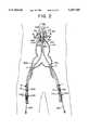
- FIG. 1is a diagrammatic view of a portion of a human vascular system depicting an abdominal aortic aneurysm which has been endoluminally bypassed in a manner previously described by Parodi et al.;
- FIG. 1Ais a diagrammatic view of a portion of a human vascular system depicting an abdominal aortic aneurysm and associated aneurysms of the left and right common iliac arteries;
- FIG. 1Bis the vasculature of FIG. 1A after exclusion of the aneurysm and attachment of a graft in conventional manner;
- FIG. 1Cis a cross-sectional view of FIG. 1A showing the placement of a bifurcated graft by a an endovascular technique previously described by Chuter et al.;
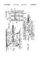
- FIG. 2is a cut-away view of the aneurysmal sac of FIG. 1A, shown in situ, with a deployment device advanced through each femoral artery in accordance with one stage of the method of the present invention;
- FIG. 3is the same view as FIG. 2 at a further stage of the method of the present invention wherein the cephalic stents have been deployed, and the right caudal stent (left side of figure) is in the deployed position;
- FIG. 4is an enlarged view of a portion of FIG. 3 at yet a further stage of the method of the present invention wherein the caudal stent is deployed within the distal common iliac artery;
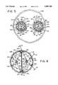
- FIG. 5is a cross-section taken along line 5--5 of FIG. 2 showing the deployment devices contained within delivery sheaths, as they may be used with the present inventive method, surrounded by normal aortic tissue prior to deployment of the cephalic stent;
- FIG. 6is a cross-section taken along line 6--6 of FIG. 3 showing the same deployment devices after deployment of the cephalic stent;
- FIG. 6Ais an enlarged detailed view of a portion of FIG. 2;
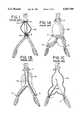
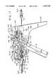
- FIG. 7is a side view of a deployment head useful with the present invention.
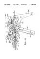
- FIG. 8is a longitudinal cross-section of the deployment head, taken essentially along line 8--8 of FIG. 5, and shown in a radially recoiled stance;
- FIG. 9is a cross-section taken along line 9--9 of FIG. 6 showing the long travel of two of the wings of the deployment head during deployment;
- FIG. 10is a cross-section taken along line 10--10 of FIG. 6 showing the short travel of the other two wings of the deployment head during deployment;
- FIG. 11is a cross-section taken along line 11--11 of FIG. 8;
- FIG. 12is a cross-section taken along line 12--12 of FIG. 8;
- FIG. 13is a cross-section taken along line 13--13 of FIG. 8;
- FIG. 14is a side view of a prosthesis mounted on an apparatus as may be used with the method of the present invention.
- FIG. 15is a top view of an actuator subassembly and a catheter mounting subassembly in assembled relationship to one another for remotely controlling the deployment head of the present invention
- FIG. 16is a front view of the assembly of FIG. 15;
- FIG. 17is a partial cross-section of one side of the assembly taken substantially along line 17--17 of FIG. 15;
- FIG. 18is a cross-section taken along line 18--18 of FIG. 17 showing the catheter mounting subassembly in spaced proximity to the actuator subassembly;
- FIG. 19is a cross-section taken along line 19--19 of FIG. 17 showing the catheter mounting subassembly and the actuator subassembly in abutting relationship to one another;
- FIG. 20is a partial cross-section of a second side of the actuator subassembly and the catheter mounting subassembly taken substantially along line 20--20 of FIG. 15;
- FIG. 21is the same view as FIG. 17 showing the operation of a trigger and an actuating lever.
- FIG. 22is a cross-section taken along the line 22--22 of FIG. 17 showing the catheter mounting subassembly and the actuator subassembly in engaging relationship to one another.
- distal and proximalrefer only to the catheter device itself and the stents being deployed, but not to the vasculature.
- the present methodcontemplates advancement of a catheter in a retrograde manner (against the flow of blood). Therefore, as the catheter is advanced distally from, for example, the femoral artery, it advances to a more proximal portion of the vasculature with respect to the heart, as understood by those skilled in the art.
- the vasculatureis referred to with respect to the cephalic (closer to head) and caudal (further from head) directions.
- the term "above”, in the context of relative positioning with respect to the aneurysm,refers to the region cephalic of the aneurysm, for example, within the aorta, whereas “below” refers to the region of the vasculature caudal of the aneurysm, for example, within the common iliac arteries.
- the present inventionprovides a method and apparatus for treating aortic aneurysms which extend to the aortoiliac junction without a suitable region at the junction of the aorta and the iliac arteries for seating a stent or other attachment device.
- seatingit is meant that the graft is implanted, fixed or otherwise attached to the vasculature.
- the present inventive method and apparatusprovide separate grafts to the aorta through each branch of the iliac arterial system. These grafts are unified upon deployment to form a new, double barrel, bifurcated graft in the vicinity of the renal arteries.
- FIG. 1there is a diagram of a vascular system that depicts, in part, the arterial system in the vicinity of the abdominal aorta.
- a tubular endoluminal grafta sufficient length of normal artery both above and below an aortic aneurysm 40 is required so that a graftstent complex 44 can be effectively seated or attached.
- the graftstent complex 44comprises a thin-walled, crimped, knitted graft 46 of polyester, expandable polytetrafluoroethelyne (ePTFE), or similar material that overlaps and is sutured to at least a cephalic stent 48.
- ePTFEexpandable polytetrafluoroethelyne
- the graftstent complex 44further includes a caudal stent 49, but the invention has application with a graftstent complex 44 having only one stent, e.g., the stent 48.
- Suitable vascular graftsthat may be used include Model 80507TW by Impra, of Tempe, Ariz.; and Model VT06070L by Cortex, of Flagstaff, Ariz.
- One stent usable with the inventionis the stent described in U.S. application Ser. No. 08/278,546 of Marin et al., filed on Jul. 19, 1994, for INTRALUMINAL STENT, the entirety of which is incorporated herein by reference.
- a stent 48anchors the tubular endoluminal graft above the aneurysm at point A and another stent 49 below the aneurysm at point B.
- a bifurcated deviceis necessary.
- FIG. 1AThe anatomic arrangement that would benefit from a bifurcated device is depicted in FIG. 1A.
- the standard vascular surgical approachrequires that a bifurcated extraluminal graft procedure be performed.
- This procedureis performed by making a large abdominal incision from the breast-bone down to the pubic bone in the middle of the abdominal wall (not shown). The intestines are pushed aside and the aneurysm is approached directly where it sits adjacent to the spine, near the patient's back. With clamps placed above the aneurysm at point A and additional clamps placed on the iliac arteries at points D and E, blood flow is controlled so that an artificial graft 42 can be sewn into position as a new conduit to replace the diseased aorta 40, as shown in FIG. 1B.
- This procedureinvolves an extensive operation and recovery period, with an intensive care unit stay and a significant period of post procedure convalescence.
- FIG. 2depicts the aneurysm 40 in the infrarenal aorta and the common iliac arteries.
- the infrarenal aortais that portion of the aorta disposed caudal of the left and right renal arteries RA. It has been empirically observed that as much as eighty percent of all abdominal aortic aneurysms occur in the infrarenal aorta. Because the aneurysm extends through the aortoiliac junction, no normal aortic arterial tissue at the caudal end of the aorta is present to which a caudal stent may be secured. Conventional vascular surgical therapies for this anatomical arrangement have been noted above, along with the difficulties posed to operators performing endoluminal bypass procedures using conventional bifurcated grafts.
- the infrarenal aortaextends caudally to the common iliac arteries which branch left and right.
- elements introduced through the left branch of the patient's vasculaturehave an "L" designation after their respective reference numerals and elements in the right branch have an "R” designation, and such elements are more generally referred to throughout this specification without such branch designations when there exists bilateral symmetry.
- Each common iliac arteryfurther branches into the internal and external iliac arteries.
- the external iliac arterybecomes the femoral artery below the inguinal ligament (not shown).
- the femoral arteryis entered within the thigh by an arterial incision where the vessel is close to the undersurface of the skin.
- a guide catheteris then introduced into the patient's vasculature.
- a guidewire 56may now be endoluminally snaked through the guide catheter and beyond to a position G in the patient's thoracic aorta, above the aneurysm 40.
- One suitable introducer catheter that may be used as the guide catheteris disclosed in U.S. application Ser. No. 08/243,190 of Marin et al., filed May 13, 1994, for DEVICE FOR DELIVERING AND DEPLOYING INTRALUMINAL DEVICES, the entirety of which is incorporated herein by reference.
- a conventional angiographic guidewire 56L,Ris inserted into each groin through incision points H and I, as shown in FIG. 2. These incisions expose the common femoral arteries on the right and left sides.
- the guidewiresare separately advanced until their distal ends are well above the aneurysm within the vasculature (point G).
- the guide wire 56is at least 0.025 inches in diameter, and preferably 0.035 inches or more.
- the guide wiremay be of tempered stainless steel and is conventionally covered with a synthetic material, such as TEFLON. The guidewire may remain in a fixed position throughout the endoluminal bypass procedure.
- guidesheaths 58R and 58Lare introduced through the incisions H and I in a conventional fashion until their distal ends are positioned just below the point of attachment for the cephalic stents.
- These guidesheaths 58L,Rfunction in conventional fashion to assist in positioning the deployment catheter within the patient's vasculature.
- two individual graftstent complexes 44L,Rare introduced separately through the guidesheaths 58L,R and deployed in such a way that the cephalic stents 48 are joined together to in effect form a bifurcated graft in situ. This is accomplished by loading individual graftstent complexes 44L,R on separate deployment catheter shafts 60L,R and introducing the catheters through incisions H and I, respectively, into the guidesheaths 58L,R.
- each of the graftstent complexeswill be long enough to extend from attachment point A to attachment point J or K.
- each cephalic stent 48L,Ris positioned on a mechanically expanding deployment head 50, as described below, but may also be deployed on a preshaped balloon, for example, a balloon that expands in a non-circular configuration, and preferably a generally "D" shaped configuration.
- the deployment catheters 60L,R with the graftstent complexes 44L,R mounted thereonare advanced through the guidesheaths 58L,R, and the cephalic stents 48 are positioned adjacent each other at the desired point of attachment A.
- the two adjacent stents 48are simultaneously deployed, in effect, forming a "double-D" configuration with the two cephalic stents 48 adhered to each other along a common surface and secured to the aorta at their outer circumference.
- the caudal stents 49L,R(FIG. 3) are positioned at the attachment points J and K.
- the caudal stents 49L,Rare preferably of the self-expanding type so that when the guidesheaths 58L,R are withdrawn, the caudal stents 49 expand automatically to attach themselves at points J and K.
- the result, as shown in FIG. 3,is that the aneurysm 40 is bypassed by the graftstent complexes 44L,R, which are hemostatically joined together by the cephalic stents 48 and are separately secured in each iliac arterial branch by the caudal stents 49L,R.
- the cephalic stents 48L,Rare deployed by a mechanical device similar to the device shown in U.S. patent application Ser. No. 08/196,278 for APPARATUS AND METHOD FOR DEPLOYMENT OF RADIALLY EXPANDABLE STENTS BY A MECHANICAL LINKAGE, filed Feb. 10, 1994, but modified to deploy the individual vascular stents in a manner such that when expanded, they are non-circular in cross-section, and preferably generally "D" shaped in cross section.
- a deployment deviceis described in detail below with reference to FIGS. 4-22.
- the site for placing the cephalic stent 48is defined, typically in the vicinity of point A, somewhat below point G, as shown in FIG. 2.
- the cephalic stentcorresponds to the stent located more distal from the respective point of incision than the caudal stent.
- An angiogramis also used to define the points for fixation of the caudal portion of each limb of the bifurcated graft, for example, in the vicinity of points J and K.
- the graftstent complex 44R of a suitable predetermined length to bypass the aortic aneurysm and the right iliac artery aneurysmmay be mounted on a deployment head 50R of a flexible catheter 60R and covered with the guidesheath 58R.
- a graftstent complex 44Lwhich may be of a different length than the graftstent complex 44R is mounted on a separate deployment head 50L and covered with a guidesheath 58L for deployment in the left arterial branch.
- the lengths of each graft 46L,Ris determined in accordance with pre-procedural angiogram and computerized axial tomogram (CT scan) data, or otherwise.
- suitable graftstent complexes 44L,Rmay be loaded onto the deployment catheters 60L,R for separate advancement to the site of the aneurysm.
- Each catheter shaft 60includes the deployment head 50 at its distal end (see FIG. 7).
- Each deployment catheter 60L,Ris separately advanced over the proximal end of a respective guidewire 56L,R and passed through the groin incision for advancement to point A, above the aneurysm.
- a fluoroscopic image of the patient's abdominal cavitymay assist locating the heads 50L,R relative to the designated site. Where heads 50L,R are formed of plastic or epoxy materials, they are advantageously provided with radiopaque portions to assist in the fluoroscopic alignment process.
- the guidesheaths 58L,Rare placed over each prosthesis for smooth delivery to the site of the aneurysm 40. Once the heads 50L,R have been advanced to a point above the aneurysm, the guidesheaths 58L,R are pulled back by a sheath retractor (not shown) to expose the cephalic stents 48L,R (FIG. 2). Each of the guidesheaths 58L,R is withdrawn prior to displacement of the wings.
- a graftwhich is smaller than permissible by conventional bifurcated graft designs transits through each iliac artery to the aorta to achieve isolated or separate reconstruction of each iliac artery.
- the reduced overall graft profileaffords the operator a safer and smoother path through the tortuous arterial system.
- each graftstent complex 44transits each iliac artery independently, there is no need for transfemoral crossover wires or catheter manipulations to draw one of the grafts 46L or 46R to the opposite side. This is distinctly different than other endoluminal bifurcated procedures, such as described above. As a result, the present invention affords reduced operative time and a safer simplified procedure.
- the cephalic stents 48L,Rmust be collaterally and rotationally aligned prior to their deployment. Collateral alignment is best determined by fluoroscopy or by intraluminal ultrasound. This involves positioning the cephalic stents 48L,R in parallel within the vasculature relative to the head. Rotational alignment can be determined by fluoroscopy or by alignment markers located on, for example, the graft material 46L,R or a proximal portion of each of the catheters 60L,R, external to the patient. Alternatively, the stents 48L,R may include a thickened portion as a marker. Other ways of providing markers are known to those skilled in the art.
- the heads 50L,Rare connected to the distal end of the catheter shafts 60L,R.
- the catheter shafts 60L,Rare rotatably supported at their proximal ends by the nose cones 114L,R of the control mechanisms 54L,R. Rotation of the respective nose cones 114L,R provides one-to-one corresponding rotation at the corresponding deployment head 50L,R.
- an operatorcan rotationally align the separately advanced stents by means of markings on the proximal end of the shafts 60L,R, external to the patient.
- FIG. 2shows the stents 48L,R collaterally aligned.
- FIG. 5shows the same stents 48L,R rotationally aligned.
- the stents 48L,Rare preferably simultaneously expanded by an actuator or control mechanism 54.
- An actuator and deployment device used with the present inventionis illustrated in the Figures and described below.
- a similar apparatus for expanding stentsis generally described in co-pending U.S. application Ser. No. 08/196,278 filed Feb. 10, 1994, the entire application being incorporated herein by reference.
- the actuatorcauses each of the deployment heads 50L,R to expand cephalic stents 48L,R beyond the elastic limit of the stent material, as shown in FIG. 3.
- the actuatorcan apply a force sufficient to restore a stenosed artery to its original, unstenosed diameter by flattening plaque or other embolic material.
- Each of the expanded stents 48L,Rcreates a friction seal against the aortic wall and against the adjacent aligned stent.
- a significant feature of the deployment device as may be used with the present inventionis that it expands stents into a non-circular, and preferably generally "D" shaped configuration.
- the pair of simultaneously expanded "D " shaped stents or cephalic stents 48have their alignment edge portions, which may be generally straight, back-to-back frictionally engage one another whereas the curved edge component of the "D " shaped stents directly engage the underlying arterial wall to seal the grafts in position.
- the collaterally and rotationally aligned stentstherefore form a bifurcated circular or oval configuration within the abdominal artery.
- the graft material 46extend along the entire alignment edge of the "D" stent while only extending partially along the curved segment, as best seen in FIG. 6A.
- FIG. 6Ashows the graft material 46L,R of each of the graftstent complexes 44L,R cut on a bias.
- the stents 48L,Rare preferably rotationally aligned so that the graft material extending along the entire margin of the stent 48L faces the graft material extending along the entire margin of the stent 48R.
- the cloth-to-cloth union of the graft materials 46L,Ris believed to be more likely to clot and seal the graftstent complexes 44L,R to one another, to the exclusion of the aneurysmal cavity 40 so as to prevent blood from flowing into the aneurysmal sac 40.
- a hemostatic sealmay be achieved between the cephalic stents 48L,R, once the stents have been deployed.
- the "D" stentneed not have a straight edge.
- Other configurationswould provide a significant surface for frictional engagement with the adjacent expanded stent, for example, sinusoidal, triangular, trapezoidal abutting edges.
- the individual "D" shaped stented graftsare preferably attached to one another and the body vessel by barbs which remain within the surface of the stent when the stent is in its unexpanded condition, but which extend from the surface of the stent when the stent is expanded.
- a suitable stent for this applicationis described in U.S. application Ser. No. unassigned of Marin et al., filed on Jul. 19, 1994, for INTRALUMINAL STENT.
- the barbsare also deployed so that when the stent contacts the surface of the blood vessel the barbs penetrate the inner lining of the blood vessel to anchor the stent in place.
- the barbspenetrate an adjacent graftstent complex 44L or 44R.
- This stent designadvantageously permits both a friction seal anchor at the time of deployment and provides a sharp puncture attachment into the arterial wall and into the graft material of the aligned adjacent stent. This provides adequate anchoring for both grafts to each other as well as each graft to the arterial wall.
- graft materialis provided along the entire margin of the expanded stent which abuts the other stent, one stent's barbs engage the covering graft material rather than the metal of the adjacent stent. This should provide a fluid tight seal between the two endoluminal grafts.
- the caudal end of each limb of the cephalically unified graftmay be attached separately within each branch of the iliac arterial system. Fixation is preferably accomplished by means of self-expanding mesh-like stents, such as described in U.S. Pat. No. 4,665,71 to Wallsten, but the invention is not so limited.
- Stents 49may be the same type as stents 48, or some other type known in the art. When loaded inside the guidesheath 58, such stents exhibit a small, collapsed profile that is substantially equivalent to the inside diameter of the containing guidesheath.
- the caudal stentself-expands in a spring-like manner to a relatively larger tubular structure.
- the guidesheath 58is shown partially withdrawn from the stent 49 in the left branch of the iliac artery, below the aneurysmal part of the vessel.
- the upper portion of the stentis illustrated as having a conical shape, the uppermost margin being fully expanded and its lower portions still being contained within the guidesheath 58 with a compressed profile.
- point M in the right arterial branch for comparisonthe stent has assumed its naturally larger, expanded configuration because the guidesheath 58R has been entirely withdrawn from the stent 49.
- This stentbears against normal tissue in the common iliac artery at J. Although not shown in the left branch, further withdrawal of the guidesheath 58L beyond point L will permit the stent in the left branch to fully expand and fix the lower limb of the graft within the patient's vasculature.
- FIG. 5shows a cross-sectional view of a body lumen 108 with the catheters 60L,R disposed therein.
- Each catheter 60terminates distally with the deployment head 50.
- one of the deployment heads 50L,Ris rotated 180° with respect to the other, however, the deployment heads are otherwise identical.
- One of the deployment heads 50L,Rhas been advanced through the body lumen 108 over the guidewire 56R whereas the other has been advanced over the guidewire 56L.
- the cephalic stent 48is mounted on the deployment head 50 which has a support surface comprised of four radially displaceable wings 52a, 52b, 52c, and 52d (see FIGS. 5 through 10). All of the wings may be dimensionally the same.
- a graft material 46is sewn at least to the cephalic stent 48 and preferably to the caudal stent 49 to form the graftstent complex 44.
- the deployment head, stent and graftare recessed within the guidesheath 58 to facilitate noninjurious advancement and withdrawal of the catheter through the patient's vasculature.
- the guidesheathis withdrawn relative to the deployment head, as noted above, prior to deployment of the stents 48L,R.
- the stents 48may have an unexpanded diameter of three to five millimeters or less for delivery purposes.
- the stent on the head 50is radially distended to an expanded diameter by a mechanical linkage actuated by the control mechanism 54, described below.
- the radial expansion of the stentis continued until at least a part of it invaginates into an arterial wall and fastens itself by a friction seal, as shown in FIG. 6.
- the wingsmay also be expanded so as to compress any deposits on the arterial wall which constrict the natural, unoccluded arterial diameter.
- the wings 52a, bare further radially displaced within the body lumen than the wings 52c,d.
- FIG. 7there is seen a longitudinal view of the head 50 which includes an annular support 59 press fit onto the distal end of an elongate flexible shaft 60.
- the shaft 60comprises a wire wound coil 66 surrounding a multilumen plastic catheter 68 (not shown).
- the catheter 68permits axial movement of several control wires which extend into the head 50 (see FIG. 13) and into the control mechanism 54 (see FIG. 18), as described below.
- the catheter 68also has a central lumen 70 that receives the proximal end of the guide wire just before the head 50 is advanced into the patient's vasculature.
- the proximal end of shaft 60is retained with the nose cone 114.
- the apparatus of the present inventiondeploys the stents 48 by radially displacing the wings 52 through a mechanical coupling that consists of a pair of arms 82,83 associated with each of the wings 52a, b (shown in FIG. 8) and a mechanical coupling of the arms 84 associated with each of the wings 52c, d (shown in FIG. 10), together with a tubular slide 86 and an initiator 88.
- the tubular slide and the initiatorare axially slideably mounted with respect to the guide wire.
- the tubular slide 86is connected to the wings 52a, b by the arms 82 and the initiator 88 is commonly associated with each of the wings 52a, b, c, d.
- the distal ends of the arms 82are pivotally attached to the distal end of the slide 86 by pins 96 through bifurcated lugs 94.
- a deployment wire 80extends from the control mechanism 54 through the shaft 60 and, at its distal end, is tied to or looped through a hole in a lug 81 at the distal end of the slide 86 (see FIG. 5).
- the proximal ends of the arms 82are pivotally attached to the distal ends of the arms 83 and an intermediate part of a corresponding wing 52a, b, by pins 118 (see FIGS. 9-11).
- the proximal ends of the arms 83, 84are pivotally mounted to the annular support 59 by pins 120, as best seen in the cross-sectional view of FIG. 13.
- tension applied to the looped deployment wire 80will cause the arms to buckle (FIGS. 9-10) which in turn deploys the wings 52a, b, c, d outwardly.
- the deployment wire 80is anchored at its proximal ends, preferably, to a multiply ribbed anchor 90 (FIG.
- the deployment wire 80is capable of transmitting compressive forces, and preferably has a diameter of 0.014 inches or less.
- the direct transmission of a physical force from the trigger 92 to the head 50causes the device of the present invention to operate substantially instantaneously without the delays associated with the filling of a balloon.
- the mechanical deviceis readily adapted (as shown in the Figures) to expand a stent in a "D" shaped configuration.
- the inventionmay be deployed by a balloon angioplasty catheter having an inflatable balloon portion that is preshaped to collaterally deploy a pair of stents 48L,R.
- the inflatable balloon portionis preshaped in a generally "D" shaped configuration.
- the actual means used to deploy the collateral stentsis not critical to the inventive method.
- a slot 98 (FIG. 7) in each of the wings 52accommodates the lugs 81, 94 and the coupling arms 82 when the wings 52a, b, c, d are recoiled. This allows for a more compact profile of the head 50 for intraluminal delivery and removal after the surgical procedure is complete.
- the head 50can be formed with a profile of approximately five millimeters.
- the head 50includes the cylindrical initiator 88 for initiating the radial motion of the wings from their recoiled configuration, as shown in FIG. 8. This makes it easier to fully deploy the wings 52a, b, when tension is applied to the deployment wire 80.
- An initiator wire 78which extends through the central lumen of the initiator 88, is anchored to the initiator in a circumferential slot 100, and is used to axially slide the initiator with respect to the arms 83, 84 (see FIG. 12).
- the slot 100is preferably formed with a pair of opposing holes 102 through which the initiator wire 78 may be threaded and wrapped securely.
- a force applied to the proximal end of the initiator wire 78 by the control mechanism 54slides the initiator 88 with respect to the guide wire 56.
- Advancement of the initiator 88 toward the distal face of the annular support 59causes it to engage sloped surfaces 104 of the arms 84 and sloped surfaces 103 of the arms 83.
- the sloped surfaces 103, 104have a 15° pitch.
- Continued proximal movement of the initiator 88causes it to bear against the sloped surface of each arm 83, 84.
- each coupling arm 82, 83, 84buckles slightly, i.e., the distal portions of the coupling arms pivot slightly away from the tubular slide 86 to initiate movement of each respectively coupled wing slightly radially outward, as perhaps best seen in FIG. 4.
- the coupling arms 82 of the wings 52a, bsimilarly pivot about the lugs 94 while the tubular slide 86 is moved slightly toward the distal face of the annular support 59.
- the portion of the initiator 88 that bears against the surfaces 103, 104is shaped as a frustrum so that frictional forces are minimized. Reduced frictional forces permit use of a thinner, more compact initiator wire 78.
- the initiator wireis 0.014 inches or less in diameter.
- the wings 52a, bcan be fully radially displaced, as shown in FIG. 9, by advancing the tubular slide 86 toward the distal face of the annular support 59 by squeezing the trigger 92 to apply tension to the deployment wire 80.
- FIG. 6shows the head 50 fully radially displaced within a body lumen 108.
- the tubular slide 86has been retracted toward the distal face of the annular support 59, as by the trigger 92, to bow the coupling arms 82, 83, 84 outward and radially separate the wings.
- the stentdeforms at four contact points 111a, 111b, 111c, and 111d into a "D" shaped configuration.
- the stentis anchored to the walls of the body lumen when the wings 52a, b have dilated substantially to the diameter of the body lumen.
- the wings 52a, bwould be dilated to approximately 35 to 40 mm. Because two stents are collaterally expanded, a mirror image of contact points 111f, g, h, and i, are formed when the stents are suitably aligned.
- a double barrel "D" shaped circularly configured bifurcated graftforms a new aortic bifurcation in the vicinity of the renal arteries extending to the region of the internal iliac arteries (FIGS. 3 and 6).
- Each of the wingspreferably has a stepped inner surface 116 to accommodate the coupling arms 82, 83, 84 (see FIG. 12).
- Each wingalso has a primary rib 122 at a distal end and a secondary rib 124 at a proximal end.
- a recess 126 between the wingsholds the stent in place (see FIGS. 7 and 9).
- the head 50 and the shaft 60form a delivery system that can be preconfigured with a particular graftstent complex 44 of suitable length for the procedure.
- a particular graftstent complex 44 of suitable length for the procedurebecause placement of the caudal stent 49 is adjusted in accordance with the particular anatomical requirements of the outflow artery, less rigorous length requirements are imposed for the selection of graft material prior to surgery. This may permit a reduced selection of graftstent complex lengths to choose between when selecting the graftstent complexes 44 for each branch of the iliac system.
- the maximum extent of expansion of the "D" stentwhich occurs along the line described by the wings 52a, b (which wings separate radially at an obtuse angle, preferably 134°), is directly controlled by the travel of the trigger 92 which governs the tubular slide 86.
- This travelcan be calibrated to a predetermined level of expansion, e.g., thirty-five mm.
- the stentcan be immediately redilatated to a larger size without the introduction of a new deployment head 50 or a catheter exchange.
- the linkage and wingsare sufficiently rigid to dilate the stent, or a stenosis to the predetermined size regardless of the presence of plaque and the like.
- the stentcan be incrementally dilated to larger sizes on a moment-by-moment basis depending on real time fluoroscopic images and the operator's discretion as a function of the actual arterial dimensions instead of relying on estimated dimensions that are conventionally made prior to the procedure using arteriography and CT scanning.
- control mechanism 54as may be used with the deployment devices inserted into each femoral artery. Several views are given so that the geometry of the control mechanism 54 can be better appreciated.
- Each control mechanismcomprises a catheter mourning subassembly 200 and an actuator subassembly 202 (FIGS. 15 and 17).
- the catheter mounting subassemblycomprises a plate 204 that supports the rotatable nose cone 114, a multiply ribbed anchor 90 attached to the proximal end of the deployment wire 80, and an anchor 242 attached to the proximal end of the initiator wire 78 (FIG. 21).
- the catheter mounting subassemblymates with a first side 206 of the actuator subassembly 202 to form an assembled control mechanism 54.
- a C-shaped retaining ring 208is attached to the proximal end of the plate 204 by a pair of screws 210 to unite the mounting subassembly 200 with the nose cone 114.
- the nose conehas a circumferential groove 212 (see FIG. 17) that permits it to be rotatably supported in the retaining ring 208 to the plate 204. It is desirable to have the nose cone rotatably supported in the catheter mounting subassembly so that the head 50 can be rotated once located within a patient's body for redistending the stent at contact points other than where the stent is first distended.
- the nose coneis provided with a stop 214, as shown in FIG. 16, that limits rotation to approximately 360°.
- a click stopmay be provided at regular intervals, for example, 45°, to provide a tactile indication of the amount of rotation brought about by rotation of the nose cone 114.
- the multiply ribbed anchor 90has at its distal end a cylindrical sleeve 91 that is slideably mounted in an annular recess 115 in the proximal face of the nose cone 114.
- FIGS. 18 and 19show cross-sections of the mounting subassembly and the actuator subassembly before and after the control mechanism 54 is assembled, respectively. Assembly is facilitated by a peg 234 and a hole 232 complementarily formed on each of the mounting subassembly and the actuator subassembly, as shown in FIG. 18, to guide the catheter mounting subassembly and the actuator subassembly together.
- the shaft 60is received in the control mechanism 54 by means of the catheter mounting subassembly 200 after the graftstent complex 44 has been loaded upon the shaft 60 and delivered to the desired location within a patient's vascular system.
- the mounting subassembly 200is then secured to the actuator subassembly 202 to form a single mechanism as by the screws 236, shown in FIG. 17, or by any other means to hold two components together.
- the mounting subassemblyenables each head 50L,R to be operated remotely by a respective trigger 92L,R, yet further provides an automatic calibration of the distention of the stent, as described below.
- the travel of triggers 92is calibrated to the radial motion of the wings so that dilation of the stent is certain and precise.
- the deployment wire 80which is coupled at its distal end to the tubular slide 86, is rigidly coupled at its proximal end to the anchor 90 by a washer 238 and a nut 240 (see FIG. 17) so that a force applied to the anchor 90 by the trigger 92 is conveyed to the tubular slide 86 to displace the wings and distend any stent thereon.
- the initiator wire 78 coupled at its distal end to the initiator 88is coupled at its proximal end to a spool-shaped anchor 242 by a washer 244 and a nut 246.
- a force applied to the anchor 242 by the actuating lever 248is thus conveyed to the initiator 88 to displace the wings slightly radially outward, as described above in connection with FIG. 8.
- proximal motion of the initiator 88causes the wings 52a, b, c, d to be slightly radially displaced.
- the trigger 92is shown coupled to the anchor 90 by a slotted yoke slide 250 terminated at the distal end in a yoke 252.
- the yoke 252selectively engages multiply ribbed the anchor 90 between any one of several ribs when the catheter mounting subassembly is assembled with the actuator subassembly (see FIG. 22). This is a self-zeroing control to account for cable bending, as more completely described in connection with the operation of the device.
- the actual set of ribs on the anchor 90 to which the yoke 252 engagesis determined based on the orientation of the shaft 60 in the patient's body.
- a link pin 254 attached to the triggerengages one of a plurality of vertical slots 256 in the yoke slide 250 so that the travel of the trigger remains accurately calibrated to the force conveyed to anchor 90 which, in turn, governs the radial displacement or recoil of the wings.
- the triggerpivots on a pin 258 in an arcuate shaped milled recess 260 formed in the second side 224 of the actuator subassembly 202. As the trigger pivots on the pin 258, the link pin 254 travels in an arc along with the trigger.
- the link pin 254draws the yoke slide 250 linearly forwards and backwards in the actuator subassembly 202 by engagement with the vertical slots 256.
- the vertical slots 256accommodate the arc traced by the link pin 254 as it travels with the trigger while translating the pivotal motion of the trigger into the linear motion of the yoke slide 250. This pivotal motion is in response to a force applied to a grasp handle 262 which may be provided to ensure a firm control over the trigger.
- the shaft 60will likely have bends in it between its distal and proximal ends. These bends will pull on the initiator and the deployment wires 78, 80 which in turn will axially reposition the anchors 90, 242 with respect to the nose cone 114 at the proximal end of the shaft 60.
- the degree of tortuositytypically is unique to each iliac branch and so the degree of bending of each the shaft 60 will likely be different. Nevertheless, the calibration of the holes 278 (see FIG. 17) remains intact because the deployment anchor 90 always engages the yoke 252 with the wings 52 in a completely recoiled stance when the catheter mounting subassembly is joined with the actuator subassembly.
- a rack 280terminated at one end with a yoke 282.
- Rack 280has an aperture 284 so that it can slide in the actuator subassembly 202 without contacting the pin 254 of the trigger 92.
- the rack 280has on a top margin thereof a set of teeth 286 that cooperate with a pinion gear 288 formed on one end of actuating lever 248.
- the actuating lever 248pivots about a pin 290 between a pair of lever stops 292a, b (see FIG. 15). From FIGS. 20 and 21, it is seen that as the actuating lever 248 pivots from 292a to 292b, the pinion gear 288 drives the rack 280 in an opposite direction and tows the anchor 242 therealong.
- An edge 264 of the trigger 92is normally biased by a spring 266 into a forward position, away from a butt 268 of the actuator subassembly.
- the spring 266is housed in a horizontal slot 270 and urges a disc 272 against the edge 264 in resistance to any force applied to the trigger.
- the trigger 92may include an aperture 274 for receiving a peg 276 from a corresponding hole in the actuator subassembly 202.
- the peg 276restrains the trigger from pivotal motion until removed from the aperture 274.
- a set of peg holes 278 extending toward the butt 268is shown for limiting the motion of the trigger to the hole in which the peg 276 has been placed.
- each of the holes 278is calibrated to the relative displacement of the wings so that the holes 278 may be labeled, for example, 20, 24, 26, 28, 30, and so on, to provide a millimeter scale of the distention of the stent upon squeezing the trigger to a particular one of the holes 278.
- the control mechanism 54includes a trigger lock mechanism that restrains the trigger from pivotal motion unless a button 300 on a top surface 302 of the control mechanism is first depressed.
- This buttonis attached to a lever lock 304 by a pivot 306 (FIGS. 20 and 21).
- the lever lock 304pivots about a pivot pin 308 and is normally biased by a spring 310 into a locked position (see FIGS. 17 and 22).
- the spring 310is connected between a pin 311 below the pivot pin 308 on the lever lock 304 and a post 312 disposed in a pair of slots 314 formed in the actuator subassembly 202.
- a pin 316(FIGS.
- the trigger 92radially displaces the wings 52a, b by the coupling of the trigger to the wings 52a, b by way of the link pin 316, the slotted yoke slide 250, the yoke 252, the multiply ribbed anchor 90, the deployment wire 80, the tubular slide 86, and the coupling arms 82.
- an angiogram and a CT scanthe operator can determine the length of the aneurysm and obtain an indication of the lumen width in the region surrounding the aneurysm.
- This indication of lumen widthis advantageously used to set the maximum travel of the trigger 92 by setting the peg 276 in an appropriate one of the calibrated holes 278.
- a suitable stent or graftstent complexmay be selected.
- the entire graftstent 44can be prefabricated and mounted on the head 50 in a manner ready for connection to the actuator subassembly 202 and subsequent deployment; a surgeon need only specify the length of the graft 46 necessary to bypass an aneurysm and the maximum distention desired of the stents 48L,R.
- the actuating lever 248is advanced from the lever stop 292a to 292b to draw the initiator 88 toward the annular support 59 and to separate the wings slightly radially.
- the trigger lock button 300can then be released and the trigger 92 compressed toward the butt 268 to draw the tubular slide 86 toward the annular support 59 and displace the wings 52a, b.
- the wings 52a, bdisplace radially outward, the distance between each wing increases and the stent, supported on the wings, assumes a radially expanded circumstance in a "D" shaped configuration.
- the trigger 92may be squeezed until it hits the peg 276 (FIG. 21).
- the stents 48L,Rmay be expanded sufficiently to anchor them to the body lumen 108 and to each other by friction.
- the stents 48L,Rengage each other through the graft material 46L,R more securely.
- Either of the stents 48L,Rcan be incrementally dilated to a larger size by removing the peg 276 and squeezing the trigger 92 beyond the hole 278 that the peg 276 formerly occupied. This may be done on a moment-by-moment basis depending on real time fluoroscopic images and the operator's discretion as a function of the actual arterial dimensions.
- the spring 266urges the trigger to its rest position which conveys a pushing force through the yoke 252 and the deployment wires 80 to the tubular slide 86.
- the tubular slide 86is pushed away from the annular support 59, the wings return to a radially recoiled stance and the stents 48L,R retain their radially expanded “D" shaped configuration.
- the nose cone 114is rotated until the markers 115 face each other (see FIG. 14). Rotation of the nose cone 114 faithfully turns the shaft 60 and the head 50 at the distal end of the shaft in substantially a one-to-one ratio, thereby rotating one of heads 50L,R with respect to the other within the body lumen 108. Once the stents 48L,R are rotationally aligned, the trigger 92 is squeezed to distend the wings 52.
- the position of the caudal stents 49L,Rare preferably adjusted prior to their deployment. Adjustment of each caudal stent 49 may be accomplished by withdrawing a respective deployment head 50L,R until it is just proximal to either of (caudal) stents 49L,R. This may be accomplished with the assistance of a fluoroscopic image of the patient's abdominal cavity. Once the deployment heads 50 have been withdrawn to this position, expansion of the wings 52 is initiated using the actuating lever 248. The heads 50 form a shelf to support the proximal margin of stents 49L,R. The heads 50 can then be slowly advanced distally (cephalically) to engage the proximal margin of each stent 49, as illustrated in FIG. 4.
- wings 52can urge the stent 49 into position while the stent is still within a respective guidesheath 58L,R. This may be necessary when stent 49 would otherwise block the mouth of the internal iliac artery (point F).
- the deployment head 50L,Ris held in position while guidesheath 58L,R is withdrawn proximally (caudally). In this manner, head 50 provides a shelf-like surface to restrain proximal (caudal) movement of the caudal stent while the caudal stent 49 is permitted to return to its naturally expanded tubular form.
- the stent 49frictionally engages the body lumen 108 within a common iliac artery.
- the graft material 46is sewn or otherwise attached to the distal (cephalic) margin of the stent 49 to complete the graftstent complex 44 (which, in this example, comprises the stent 48, the graft material 46, and the stent 49).
- the head 50is formed of plastic or epoxy materials, it is advantageously provided with a radiopaque portion to assist in the fluoroscopic alignment process.
- the direct transmission of a physical force from the trigger 92 to the head 50permits rapid displacement and recoil of the wings. Displacement and recoil can be performed in virtually less than a second, as compared to the time required for balloon dilatation which, in the case of relatively large balloons with conventionally sized inflation lumens, may be as much as twenty to thirty seconds and sometimes up to a minute. Relative to balloon based devices, therefore, the present invention operates substantially instantaneously without the delays associated with filling and emptying a balloon. All the while, intraluminal fluids flow between the radially displaced wings to the vasculature in the region of the device deployment.
- Each of wires 78 and 80is preferably stainless steel.
- the head 50may be produced in a disposable or non-disposable fashion. Where the head 50 is to be disposed of after usage, at least the wings 52, the tubular slide 86, the coupling arms 82, 83, 84, the initiator 88, and the annular support 59 may be compression molded or extruded from an epoxy material or plastic.
- the same components of the head 50 listed aboveare advantageously formed of stainless steel where the head 50 is intended to be reused in a subsequent procedure.
- One skilled in the artwould recognize that the choice of materials for the head affects the radiopacity of the head. Thus, an epoxy or plastic head would be radiolucid as compared to a stainless steel head which would be radiopaque.
- the guidesheath 58may be of a plastic or teflon material.
- the materials most commonly used as prosthetic arterial graftsare PTFE ("GORTEX”), expanded PTFE, and polyester (“DACRON”), however, other suitable grafts may be used with this device.
- No single prosthetic materialhas surfaced as being superior to others. Excellent results may also be achieved using a patient's own accessory vein, albeit with more imposition to the patient.
- the inventionis intended for use in deploying stents and attachment devices, i.e., devices which may be attached to a body lumen such as an artery, for example to secure a graft in place, in the vicinity of a vasculature bifurcation.
- stentis intended to also include such attachment devices.
- the inventioncan be used with any radially expandable stent, including stents that are partially self-expanding.
- the inventionhas application in other portions of the vasculature, such as where a segment of arterial tissue in the vicinity of a vasculature bifurcation must be bypassed.
- thismay be at the aortic artery bifurcation, at the iliac artery bifurcation, and at the innominate artery bifurcation.
- the inventionhas application in body passageways other than arteries which branch from a common passageway and require treatment in the vicinity of the branching passageways.
- the inventionhas utility in the treatment of tracheal esophageal fistulae when the deployment heads 50 are introduced through a patient's mouth to isolate a pathological connection.
- the trachea and esophagusmay be isolated by deploying on one side of the pathological connection the stents 49L,R of the graftstent complexes 44 in the left and right bronchi and deploying the stents 48L,R in the trachea on the other side.
- a malignant obstruction in the tracheamay be excluded from the windpipe by deploying graftstent complexes 44 as previously described.
- the inventionmay be used to treat a stenosis or injury, for example, a hole, in the left or right ureter, by introducing the deployment heads 50L,R through the urethra and deploying the stents 49L,R at one end of the graftstent complexes 44 in a respective one of the left and right ureters and the stents 48L,R at the other end within the urinary bladder.
- the portion of the graftstent complexes 44 that extend into branched passagewaysmay be attached in the branched passageways prior to aligning and attaching the stents in a common passageway.
- Such a procedureis appropriate when the operator enters the body passageway at a location more proximal to the common passageway.
- the caudal portion of each graftstent complex 44L, Ris positioned within a respective one of the iliac arteries before the stents 48L,R are aligned and deployed.
- the graftstent complexes 44include the caudal stents 49L,R, then these stents are deployed or expanded in the iliac arteries prior to aligning and deploying the stents 48L,R. Further, with reference to the foregoing exemplary applications, it is contemplated that the caudal portions of the graftstent complexes 44 are positioned and deployed before positioning and deploying the cephalic stents 48L,R in the treatment of tracheal esophageal fistulae, malignant tracheal obstructions, and ureteral dysfunctions.
- the pathological defectis isolated by advancing a pair of graftstent complexes, which have been previously loaded on catheter devices, along a pair of guidewires which have been previously positioned in branched passageways which communicate with the common passageway.
- the graftstent complexesinclude at least a stent and a portion of graft material; however, it is preferred that the graftstent complexes include a pair of stents 48, 49, one connected to each end of the graft.
- a first stent(here 49L,R) is deployed in each of the branched passageways to secure the graftstent complexes on one side of the pathological defect within the branched passageways.
- the stentsmay be positioned, for example, so as to not stretch across the ostium of another passageway branching from the branched passageway, or so as to extend beyond the pathological defect to one side of the defect. This may be accomplished as described above in connection with FIG. 4.
- the first stentsare preferably of the self expanding variety, that is, they are mechanically or thermally activated, so that when guidesheath 58 is withdrawn, the stents expand into contact with the body passageway.
- the second stents of the graftstent complexesmay be aligned within the common passageway, as through the use of markers, as previously described.
- the second stentsare coaxially positioned on the deployment heads 50L,R by withdrawing each deployment head 50L,R until the second stents pass over the secondary rib 124 of each wing 52.
- the second stents(here stents 48L,R) have an inside diameter that is greater than the diameter of the wings 52 at the radial cross-section of the secondary rib 124, yet less than the diameter of the wings 52 at the radial cross-section of the primary rib 122 (see FIG. 7), so that the second stents can readily be mounted on the wings 52.
- radiopaque or other markerscan be used instead, or in addition, to ascertain whether the second stents have been coaxially positioned over the deployment member.
- the pathological defectmay be, for example, an aneurysm or an occlusion such as a cancer.
- a graftstent complexis introduced through a common passageway and advanced toward branched passageways of the type in which fluid flows from in the direction of the branched passageways, for example, from the aorta to the iliac arteries, then the fluid flow, for example, blood, will naturally carry the graft over the guidewire and into position, without the need for a stent to be deployed in the branched passageways, nor the need for withdrawing a stent deployment means from the branched passageways. All that is required in this alternative configuration is that the graft be selected of a material and sidewall construction that resists collapsing and twisting.
- the "term” fluid as used hereinis meant to embrace any gas that flows, for example, air.
Landscapes
- Health & Medical Sciences (AREA)
- Engineering & Computer Science (AREA)
- Biomedical Technology (AREA)
- General Health & Medical Sciences (AREA)
- Veterinary Medicine (AREA)
- Public Health (AREA)
- Heart & Thoracic Surgery (AREA)
- Vascular Medicine (AREA)
- Life Sciences & Earth Sciences (AREA)
- Animal Behavior & Ethology (AREA)
- Transplantation (AREA)
- Oral & Maxillofacial Surgery (AREA)
- Cardiology (AREA)
- Gastroenterology & Hepatology (AREA)
- Pulmonology (AREA)
- Anesthesiology (AREA)
- Hematology (AREA)
- Prostheses (AREA)
- Media Introduction/Drainage Providing Device (AREA)
- Transition And Organic Metals Composition Catalysts For Addition Polymerization (AREA)
- Medicines That Contain Protein Lipid Enzymes And Other Medicines (AREA)
Abstract
Description
Claims (39)
Priority Applications (18)
| Application Number | Priority Date | Filing Date | Title |
|---|---|---|---|
| US08/324,893US5507769A (en) | 1994-10-18 | 1994-10-18 | Method and apparatus for forming an endoluminal bifurcated graft |
| PT95936225TPT786972E (en) | 1994-10-18 | 1995-09-27 | APPARATUS FOR FORMING A BOLTED ENDOLUMINAL ENCLOSURE |
| EP95936225AEP0786972B1 (en) | 1994-10-18 | 1995-09-27 | Apparatus for forming an endoluminal bifurcated graft |
| DE69532507TDE69532507T2 (en) | 1994-10-18 | 1995-09-27 | DEVICE FOR MANUFACTURING AN ENDOLUMINAL, DIVERSE Vascular PROSTHESIS |
| PCT/US1995/012582WO1996011648A1 (en) | 1994-10-18 | 1995-09-27 | Method and apparatus for forming an endoluminal bifurcated graft |
| AU38250/95AAU3825095A (en) | 1994-10-18 | 1995-09-27 | Method and apparatus for forming an endoluminal bifurcated graft |
| EP09075048AEP2103277B1 (en) | 1994-10-18 | 1995-09-27 | Apparatus for deploying stents |
| ES95936225TES2215177T3 (en) | 1994-10-18 | 1995-09-27 | AN APPARATUS FOR FORMING A FORKED ENDOLUMINAL GRAFT. |
| DE69535918TDE69535918D1 (en) | 1994-10-18 | 1995-09-27 | Device for the rotational alignment of a stent pair |
| AT02028214TATE422859T1 (en) | 1994-10-18 | 1995-09-27 | DEVICE FOR THE ROTATORIAL ALIGNMENT OF A PAIR OF STENTS |
| ES09075048TES2392621T3 (en) | 1994-10-18 | 1995-09-27 | Device for deploying cannulas |
| JP51325896AJP3919024B2 (en) | 1994-10-18 | 1995-09-27 | Method and apparatus for forming an endoluminal bifurcated graft |
| DK95936225TDK0786972T3 (en) | 1994-10-18 | 1995-09-27 | Apparatus for the preparation of an endoluminal two-branch graft |
| EP02028214AEP1290989B1 (en) | 1994-10-18 | 1995-09-27 | Apparatus for rotationally aligning a pair of indwelling stents |
| AT95936225TATE258413T1 (en) | 1994-10-18 | 1995-09-27 | DEVICE FOR PRODUCING AN ENDOLUMINAL BRANCH VASCULAR PROSTHESIS |
| US08/537,630US5695517A (en) | 1994-02-10 | 1995-10-02 | Method and apparatus for forming an endoluminal bifurcated graft |
| US09/504,732US6168610B1 (en) | 1994-02-10 | 2000-02-16 | Method for endoluminally excluding an aortic aneurysm |
| US09/709,798US6575994B1 (en) | 1994-02-10 | 2000-11-10 | Method and apparatus concerning bypass grafts |
Applications Claiming Priority (1)
| Application Number | Priority Date | Filing Date | Title |
|---|---|---|---|
| US08/324,893US5507769A (en) | 1994-10-18 | 1994-10-18 | Method and apparatus for forming an endoluminal bifurcated graft |
Related Parent Applications (1)
| Application Number | Title | Priority Date | Filing Date |
|---|---|---|---|
| US08/196,278Continuation-In-PartUS5443477A (en) | 1994-02-10 | 1994-02-10 | Apparatus and method for deployment of radially expandable stents by a mechanical linkage |
Related Child Applications (2)
| Application Number | Title | Priority Date | Filing Date |
|---|---|---|---|
| US08/537,630DivisionUS5695517A (en) | 1994-02-10 | 1995-10-02 | Method and apparatus for forming an endoluminal bifurcated graft |
| US08/838,126DivisionUS6039749A (en) | 1994-02-10 | 1997-04-15 | Method and apparatus for deploying non-circular stents and graftstent complexes |
Publications (1)
| Publication Number | Publication Date |
|---|---|
| US5507769Atrue US5507769A (en) | 1996-04-16 |
Family
ID=23265557
Family Applications (2)
| Application Number | Title | Priority Date | Filing Date |
|---|---|---|---|
| US08/324,893Expired - LifetimeUS5507769A (en) | 1994-02-10 | 1994-10-18 | Method and apparatus for forming an endoluminal bifurcated graft |
| US08/537,630Expired - LifetimeUS5695517A (en) | 1994-02-10 | 1995-10-02 | Method and apparatus for forming an endoluminal bifurcated graft |
Family Applications After (1)
| Application Number | Title | Priority Date | Filing Date |
|---|---|---|---|
| US08/537,630Expired - LifetimeUS5695517A (en) | 1994-02-10 | 1995-10-02 | Method and apparatus for forming an endoluminal bifurcated graft |
Country Status (10)
| Country | Link |
|---|---|
| US (2) | US5507769A (en) |
| EP (3) | EP2103277B1 (en) |
| JP (1) | JP3919024B2 (en) |
| AT (2) | ATE422859T1 (en) |
| AU (1) | AU3825095A (en) |
| DE (2) | DE69535918D1 (en) |
| DK (1) | DK0786972T3 (en) |
| ES (2) | ES2392621T3 (en) |
| PT (1) | PT786972E (en) |
| WO (1) | WO1996011648A1 (en) |
Cited By (340)
| Publication number | Priority date | Publication date | Assignee | Title |
|---|---|---|---|---|
| WO1997003717A1 (en)* | 1995-07-19 | 1997-02-06 | Endotex Interventional Systems, Inc. | Methods and apparatus for treating aneurysms |
| WO1997017911A1 (en)* | 1995-11-10 | 1997-05-22 | Endogad Research Pty Limited | Positioning an intraluminal graft using a guidewire and a catheter therefor |
| US5662614A (en)* | 1995-05-09 | 1997-09-02 | Edoga; John K. | Balloon expandable universal access sheath |
| WO1997040779A1 (en)* | 1996-04-25 | 1997-11-06 | Corvita Europe | Intraluminal endoprosthesis for ramifying the ducts of a human or animal body and method of manufacture thereof |
| US5759186A (en)* | 1991-06-14 | 1998-06-02 | Ams Medinvent S.A. | Transluminal Implantation device |
| US5769885A (en)* | 1991-04-11 | 1998-06-23 | Endovascular Technologies, Inc. | Bifurcated multicapsule intraluminal grafting system and method |
| WO1998030156A1 (en) | 1997-01-14 | 1998-07-16 | Teramed Incorporated | Method for forming custom length grafts after endoluminal insertion |
| WO1998019634A3 (en)* | 1996-11-07 | 1998-09-11 | Vascular Science Inc | Medical grafting methods and apparatus |
| US5824040A (en)* | 1995-12-01 | 1998-10-20 | Medtronic, Inc. | Endoluminal prostheses and therapies for highly variable body lumens |
| US5824037A (en)* | 1995-10-03 | 1998-10-20 | Medtronic, Inc. | Modular intraluminal prostheses construction and methods |
| US5824055A (en)* | 1997-03-25 | 1998-10-20 | Endotex Interventional Systems, Inc. | Stent graft delivery system and methods of use |
| WO1998047447A1 (en)* | 1997-04-23 | 1998-10-29 | Dubrul William R | Bifurcated stent and distal protection system |
| US5843119A (en)* | 1996-10-23 | 1998-12-01 | United States Surgical Corporation | Apparatus and method for dilatation of a body lumen and delivery of a prothesis therein |
| US5843166A (en)* | 1997-01-17 | 1998-12-01 | Meadox Medicals, Inc. | Composite graft-stent having pockets for accomodating movement |
| EP0810004A3 (en)* | 1996-05-29 | 1999-01-13 | Advanced Cardiovascular Systems, Inc. | Radiation-emitting flow-through temporary stent |
| US5941908A (en)* | 1997-04-23 | 1999-08-24 | Vascular Science, Inc. | Artificial medical graft with a releasable retainer |
| US5957974A (en)* | 1997-01-23 | 1999-09-28 | Schneider (Usa) Inc | Stent graft with braided polymeric sleeve |
| US5961545A (en)* | 1997-01-17 | 1999-10-05 | Meadox Medicals, Inc. | EPTFE graft-stent composite device |
| US5972017A (en)* | 1997-04-23 | 1999-10-26 | Vascular Science Inc. | Method of installing tubular medical graft connectors |
| US5976178A (en)* | 1996-11-07 | 1999-11-02 | Vascular Science Inc. | Medical grafting methods |
| US6001124A (en)* | 1997-10-09 | 1999-12-14 | Vascular Science, Inc. | Oblique-angle graft connectors |
| US6015431A (en)* | 1996-12-23 | 2000-01-18 | Prograft Medical, Inc. | Endolumenal stent-graft with leak-resistant seal |
| US6030415A (en)* | 1997-01-29 | 2000-02-29 | Endovascular Technologies, Inc. | Bell-bottom modular stent-graft |
| US6036723A (en)* | 1996-05-02 | 2000-03-14 | B. Braun Celsa | Surgically anastomosable transcutaneous vascular prothesis and set comprising the same |
| US6036702A (en)* | 1997-04-23 | 2000-03-14 | Vascular Science Inc. | Medical grafting connectors and fasteners |
| US6048362A (en)* | 1998-01-12 | 2000-04-11 | St. Jude Medical Cardiovascular Group, Inc. | Fluoroscopically-visible flexible graft structures |
| US6059821A (en)* | 1996-05-02 | 2000-05-09 | B. Braun Celsa (Societe Anonyme) | Method for controlling circulation of blood in a body |
| US6068654A (en)* | 1997-12-23 | 2000-05-30 | Vascular Science, Inc. | T-shaped medical graft connector |
| US6074416A (en)* | 1997-10-09 | 2000-06-13 | St. Jude Medical Cardiovascular Group, Inc. | Wire connector structures for tubular grafts |
| US6110198A (en)* | 1995-10-03 | 2000-08-29 | Medtronic Inc. | Method for deploying cuff prostheses |
| US6113612A (en)* | 1998-11-06 | 2000-09-05 | St. Jude Medical Cardiovascular Group, Inc. | Medical anastomosis apparatus |
| US6117117A (en)* | 1998-08-24 | 2000-09-12 | Advanced Cardiovascular Systems, Inc. | Bifurcated catheter assembly |
| US6120432A (en)* | 1997-04-23 | 2000-09-19 | Vascular Science Inc. | Medical grafting methods and apparatus |
| US6129756A (en)* | 1998-03-16 | 2000-10-10 | Teramed, Inc. | Biluminal endovascular graft system |
| US6142926A (en)* | 1996-08-29 | 2000-11-07 | Advanced Cardiovascular Systems, Inc. | Radiation dose delivery catheter with reinforcing mandrel |
| US6152937A (en)* | 1998-11-06 | 2000-11-28 | St. Jude Medical Cardiovascular Group, Inc. | Medical graft connector and methods of making and installing same |
| US6152956A (en)* | 1997-01-28 | 2000-11-28 | Pierce; George E. | Prosthesis for endovascular repair of abdominal aortic aneurysms |
| US6159140A (en)* | 1998-02-17 | 2000-12-12 | Advanced Cardiovascular Systems | Radiation shielded catheter for delivering a radioactive source and method of use |
| US6159139A (en)* | 1998-02-17 | 2000-12-12 | Advanced Cardiovascular Systems Inc. | Radiation delivery catheter with a spring wire centering mechanism |
| US6165140A (en) | 1998-12-28 | 2000-12-26 | Micrus Corporation | Composite guidewire |
| US6168610B1 (en)* | 1994-02-10 | 2001-01-02 | Endovascular Systems, Inc. | Method for endoluminally excluding an aortic aneurysm |
| US6179860B1 (en) | 1998-08-19 | 2001-01-30 | Artemis Medical, Inc. | Target tissue localization device and method |
| US6203550B1 (en) | 1998-09-30 | 2001-03-20 | Medtronic, Inc. | Disposable delivery device for endoluminal prostheses |
| US6210312B1 (en) | 1997-05-20 | 2001-04-03 | Advanced Cardiovascular Systems, Inc. | Catheter and guide wire assembly for delivery of a radiation source |
| US6210429B1 (en) | 1996-11-04 | 2001-04-03 | Advanced Stent Technologies, Inc. | Extendible stent apparatus |
| US6214036B1 (en) | 1998-11-09 | 2001-04-10 | Cordis Corporation | Stent which is easily recaptured and repositioned within the body |
| US6221098B1 (en) | 1997-08-13 | 2001-04-24 | Advanced Cardiovascular Systems, Inc. | Stent and catheter assembly and method for treating bifurcations |
| US6221006B1 (en) | 1998-02-10 | 2001-04-24 | Artemis Medical Inc. | Entrapping apparatus and method for use |
| US6224609B1 (en) | 1998-03-16 | 2001-05-01 | Teramed Inc. | Bifurcated prosthetic graft |
| US6224535B1 (en) | 1998-02-17 | 2001-05-01 | Advanced Cardiovascular Systems, Inc. | Radiation centering catheters |
| US6235054B1 (en) | 1998-02-27 | 2001-05-22 | St. Jude Medical Cardiovascular Group, Inc. | Grafts with suture connectors |
| US6235050B1 (en)* | 1994-05-12 | 2001-05-22 | Endovascular Technologies, Inc. | System and method for intraluminally deploying a bifurcated graft |
| US20010001827A1 (en)* | 1998-03-09 | 2001-05-24 | Chapman Troy J. | Anastomosis device and method |
| US6270525B1 (en) | 1999-09-23 | 2001-08-07 | Cordis Corporation | Precursor stent gasket for receiving bilateral grafts having controlled contralateral guidewire access |
| US6273909B1 (en) | 1998-10-05 | 2001-08-14 | Teramed Inc. | Endovascular graft system |
| US6280467B1 (en) | 1998-02-26 | 2001-08-28 | World Medical Manufacturing Corporation | Delivery system for deployment and endovascular assembly of a multi-stage stented graft |
| US6287335B1 (en) | 1999-04-26 | 2001-09-11 | William J. Drasler | Intravascular folded tubular endoprosthesis |
| US6290731B1 (en) | 1998-03-30 | 2001-09-18 | Cordis Corporation | Aortic graft having a precursor gasket for repairing an abdominal aortic aneurysm |
| US6325826B1 (en) | 1998-01-14 | 2001-12-04 | Advanced Stent Technologies, Inc. | Extendible stent apparatus |
| US6331188B1 (en) | 1994-08-31 | 2001-12-18 | Gore Enterprise Holdings, Inc. | Exterior supported self-expanding stent-graft |
| US6352561B1 (en) | 1996-12-23 | 2002-03-05 | W. L. Gore & Associates | Implant deployment apparatus |
| US6352553B1 (en) | 1995-12-14 | 2002-03-05 | Gore Enterprise Holdings, Inc. | Stent-graft deployment apparatus and method |
| US6352531B1 (en) | 1999-03-24 | 2002-03-05 | Micrus Corporation | Variable stiffness optical fiber shaft |
| US6361637B2 (en) | 1995-12-14 | 2002-03-26 | Gore Enterprise Holdings, Inc. | Method of making a kink resistant stent-graft |
| US6368345B1 (en)* | 1998-09-30 | 2002-04-09 | Edwards Lifesciences Corporation | Methods and apparatus for intraluminal placement of a bifurcated intraluminal garafat |
| US6371982B2 (en) | 1997-10-09 | 2002-04-16 | St. Jude Medical Cardiovascular Group, Inc. | Graft structures with compliance gradients |
| US6383213B2 (en) | 1999-10-05 | 2002-05-07 | Advanced Cardiovascular Systems, Inc. | Stent and catheter assembly and method for treating bifurcations |
| US6387120B2 (en) | 1999-12-09 | 2002-05-14 | Advanced Cardiovascular Systems, Inc. | Stent and catheter assembly and method for treating bifurcations |
| US6391036B1 (en) | 1998-01-30 | 2002-05-21 | St. Jude Medical Atg Inc. | Medical graft connector or plug structures, and methods of making and installing same |
| US6395019B2 (en) | 1998-02-09 | 2002-05-28 | Trivascular, Inc. | Endovascular graft |
| US6409750B1 (en) | 1999-02-01 | 2002-06-25 | Board Of Regents, The University Of Texas System | Woven bifurcated and trifurcated stents and methods for making the same |
| US20020082627A1 (en)* | 1998-01-30 | 2002-06-27 | Berg Todd Allen | Medical graft connector or plug structures, and methods of making and installing same |
| US20020082614A1 (en)* | 1999-06-04 | 2002-06-27 | St. Jude Medical Cardiovascular Group, Inc. | Medical grafting apparatus and methods |
| US20020087046A1 (en)* | 1997-04-23 | 2002-07-04 | St. Jude Medical Cardiovascular Group, Inc. | Medical grafting methods and apparatus |
| US20020091398A1 (en)* | 1999-11-30 | 2002-07-11 | St. Jude Medical Cardiovascular Group, Inc. | Medical grafting methods and apparatus |
| US6428567B2 (en) | 1997-08-13 | 2002-08-06 | Advanced Cardiovascular Systems, Inc. | Stent and catheter assembly and method for treating bifurcations |
| US20020108621A1 (en)* | 1998-11-06 | 2002-08-15 | St. Jude Medical Cardiovascular Group, Inc. | Medical grafting methods and apparatus |
| US20020124851A1 (en)* | 2000-11-28 | 2002-09-12 | Richard Knauer | Hearing protective device and method of making same |
| US20020133153A1 (en)* | 2001-01-16 | 2002-09-19 | Hyde Edward R. | Transosseous core approach and instrumentation for joint replacement and repair |
| US6475222B1 (en) | 1998-11-06 | 2002-11-05 | St. Jude Medical Atg, Inc. | Minimally invasive revascularization apparatus and methods |
| US6478813B1 (en) | 1997-08-01 | 2002-11-12 | Peter T. Keith | Method for joining grafts in a common body passageway |
| US20020169466A1 (en)* | 2001-05-14 | 2002-11-14 | St. Jude Medical Atg, Inc. | Medical grafting methods and apparatus |
| US20020183787A1 (en)* | 2001-06-01 | 2002-12-05 | Velocimed, L.L.C. | Closure devices, related delivery methods and tools, and related methods of use |
| US20020183769A1 (en)* | 2001-05-30 | 2002-12-05 | St. Jude Medical Atg, Inc. | Medical grafting methods and apparatus |
| US20030004560A1 (en)* | 2001-04-11 | 2003-01-02 | Trivascular, Inc. | Delivery system and method for bifurcated graft |
| US6511491B2 (en) | 1999-03-09 | 2003-01-28 | St. Jude Medical Atg, Inc. | Medical grafting methods and apparatus |
| US20030033002A1 (en)* | 1998-09-30 | 2003-02-13 | Edwards Lifesciences, Llc | Aorto uni-iliac graft |
| US20030040771A1 (en)* | 1999-02-01 | 2003-02-27 | Hideki Hyodoh | Methods for creating woven devices |
| US6533811B1 (en) | 1993-07-08 | 2003-03-18 | Medtronic, Inc. | Internal graft prosthesis and delivery system |
| US6540734B1 (en) | 2000-02-16 | 2003-04-01 | Advanced Cardiovascular Systems, Inc. | Multi-lumen extrusion tubing |
| US6544219B2 (en) | 2000-12-15 | 2003-04-08 | Advanced Cardiovascular Systems, Inc. | Catheter for placement of therapeutic devices at the ostium of a bifurcation of a body lumen |
| US20030074058A1 (en)* | 2001-10-16 | 2003-04-17 | Scimed Life Systems, Inc. | Aortic artery aneurysm endovascular prosthesis |
| US20030074048A1 (en)* | 2001-10-16 | 2003-04-17 | Scimed Life Systems, Inc. | Tubular prosthesis for external agent delivery |
| US6551350B1 (en) | 1996-12-23 | 2003-04-22 | Gore Enterprise Holdings, Inc. | Kink resistant bifurcated prosthesis |
| US6576009B2 (en) | 1995-12-01 | 2003-06-10 | Medtronic Ave, Inc. | Bifurcated intraluminal prostheses construction and methods |
| USRE38146E1 (en) | 1992-01-08 | 2003-06-17 | Cordis Corporation | Method and apparatus for bilateral intra-aortic bypass |
| US6582417B1 (en) | 1999-09-22 | 2003-06-24 | Advanced Cardiovascular Systems, Inc. | Methods and apparatuses for radiation treatment |
| US6582394B1 (en) | 2000-11-14 | 2003-06-24 | Advanced Cardiovascular Systems, Inc. | Stent and catheter assembly and method for treating bifurcated vessels |
| US20030120331A1 (en)* | 2001-12-20 | 2003-06-26 | Trivascular, Inc. | Advanced endovascular graft |
| US6602265B2 (en) | 1998-02-10 | 2003-08-05 | Artemis Medical, Inc. | Tissue separation medical device and method |
| US6605031B1 (en) | 1999-09-22 | 2003-08-12 | Advanced Cardiovascular Systems, Inc. | Stepped centering balloon for optimal radiation delivery |
| US20030153970A1 (en)* | 2002-02-14 | 2003-08-14 | Rao Doreen S. | System for maintaining body canal patency and method thereof |
| US20030153933A1 (en)* | 1998-01-23 | 2003-08-14 | Bolduc Lee R. | System for performing vascular anastomoses |
| US6607539B1 (en) | 2001-05-18 | 2003-08-19 | Endovascular Technologies, Inc. | Electric endovascular implant depolyment system |
| US6613072B2 (en) | 1994-09-08 | 2003-09-02 | Gore Enterprise Holdings, Inc. | Procedures for introducing stents and stent-grafts |
| US20030181923A1 (en)* | 1996-11-04 | 2003-09-25 | Gil Vardi | Methods for deploying stents in bifurcations |
| US6626938B1 (en) | 2000-11-16 | 2003-09-30 | Cordis Corporation | Stent graft having a pleated graft member |
| US20030195606A1 (en)* | 1999-09-23 | 2003-10-16 | Advanced Stent Technologies, Inc., A Delaware Corporation | Bifurcation stent system and method |
| US6635068B1 (en) | 1998-02-10 | 2003-10-21 | Artemis Medical, Inc. | Occlusion, anchoring, tensioning and flow direction apparatus and methods for use |
| US20030208232A1 (en)* | 2002-05-06 | 2003-11-06 | Velocimed, L.L.C. | PFO closure devices and related methods of use |
| US6648911B1 (en) | 2000-11-20 | 2003-11-18 | Avantec Vascular Corporation | Method and device for the treatment of vulnerable tissue site |
| US6649030B1 (en) | 2000-08-31 | 2003-11-18 | Endovascular Technologies, Inc. | Physical vapor deposition of radiopaque markings on a graft |
| US20030220681A1 (en)* | 2000-02-02 | 2003-11-27 | Trivascular, Inc. | Delivery system and method for expandable intracorporeal device |
| US6660030B2 (en)* | 1998-12-11 | 2003-12-09 | Endologix, Inc. | Bifurcation graft deployment catheter |
| US6682536B2 (en) | 2000-03-22 | 2004-01-27 | Advanced Stent Technologies, Inc. | Guidewire introducer sheath |
| US6689157B2 (en) | 1999-07-07 | 2004-02-10 | Endologix, Inc. | Dual wire placement catheter |
| US6689156B1 (en) | 1999-09-23 | 2004-02-10 | Advanced Stent Technologies, Inc. | Stent range transducers and methods of use |
| US6692483B2 (en) | 1996-11-04 | 2004-02-17 | Advanced Stent Technologies, Inc. | Catheter with attached flexible side sheath |
| US6709440B2 (en) | 2001-05-17 | 2004-03-23 | Advanced Cardiovascular Systems, Inc. | Stent and catheter assembly and method for treating bifurcations |
| US6712836B1 (en) | 1999-05-13 | 2004-03-30 | St. Jude Medical Atg, Inc. | Apparatus and methods for closing septal defects and occluding blood flow |
| US6716223B2 (en) | 2001-11-09 | 2004-04-06 | Micrus Corporation | Reloadable sheath for catheter system for deploying vasoocclusive devices |
| US20040073240A1 (en)* | 1995-02-24 | 2004-04-15 | Bolduc Lee R. | Surgical clips and methods for tissue approximation |
| US20040073287A1 (en)* | 1994-02-09 | 2004-04-15 | George Goicoechea | Bifurcated endoluminal prosthesis |
| US6730119B1 (en) | 2000-10-06 | 2004-05-04 | Board Of Regents Of The University Of Texas System | Percutaneous implantation of partially covered stents in aneurysmally dilated arterial segments with subsequent embolization and obliteration of the aneurysm cavity |
| US20040111145A1 (en)* | 2002-11-27 | 2004-06-10 | Francesco Serino | Vascular prosthesis for the treatment of abdominal aortic aneurysms, using a combined laparoscopic/ open and endovascular technique, and delivery system for releasing a prosthesis fitted with anchoring stents |
| US6758858B2 (en) | 1995-03-10 | 2004-07-06 | Bard Peripheral Vascular, Inc. | Diametrically adaptable encapsulated stent and methods for deployment thereof |
| US6790226B2 (en) | 1995-03-10 | 2004-09-14 | Bard Peripheral Vascular, Inc. | Endoluminal prosthesis with support wire |
| US20040186490A1 (en)* | 1995-02-24 | 2004-09-23 | Gifford Hanson S. | Devices and methods for performing avascular anastomosis |
| US20040193245A1 (en)* | 2003-03-26 | 2004-09-30 | The Foundry, Inc. | Devices and methods for treatment of abdominal aortic aneurysm |
| US20040199240A1 (en)* | 2001-07-06 | 2004-10-07 | Jurgen Dorn | Delivery system having a rapid pusher assembly for self-expanding stent, and stent exchange configuration |
| US20040200876A1 (en)* | 1994-06-17 | 2004-10-14 | Bolduc Lee R. | Surgical stapling instrument and method thereof |
| US20040204754A1 (en)* | 2003-04-14 | 2004-10-14 | Anvil Medical, Inc. | Stent for placement at luminal os |
| US20040243221A1 (en)* | 2003-05-27 | 2004-12-02 | Fawzi Natalie V. | Endovascular graft including substructure for positioning and sealing within vasculature |
| US6835203B1 (en) | 1996-11-04 | 2004-12-28 | Advanced Stent Technologies, Inc. | Extendible stent apparatus |
| US20040267306A1 (en)* | 2003-04-11 | 2004-12-30 | Velocimed, L.L.C. | Closure devices, related delivery methods, and related methods of use |
| US6843802B1 (en) | 2000-11-16 | 2005-01-18 | Cordis Corporation | Delivery apparatus for a self expanding retractable stent |
| US6849087B1 (en) | 1999-10-06 | 2005-02-01 | Timothy A. M. Chuter | Device and method for staged implantation of a graft for vascular repair |
| US20050027287A1 (en)* | 1999-03-24 | 2005-02-03 | O'connor Michael J. | Variable stiffness heating catheter |
| US20050033361A1 (en)* | 2003-06-16 | 2005-02-10 | Galdonik Jason A. | Temporary hemostatic plug apparatus and method of use |
| US20050033416A1 (en)* | 2003-05-02 | 2005-02-10 | Jacques Seguin | Vascular graft and deployment system |
| US20050038493A1 (en)* | 2001-10-02 | 2005-02-17 | Jorg Feeser | Stent delivery system |
| US6884258B2 (en) | 1999-06-04 | 2005-04-26 | Advanced Stent Technologies, Inc. | Bifurcation lesion stent delivery using multiple guidewires |
| US6887268B2 (en) | 1998-03-30 | 2005-05-03 | Cordis Corporation | Extension prosthesis for an arterial repair |
| US20050171593A1 (en)* | 2004-01-30 | 2005-08-04 | Trivascular, Inc. | Inflatable porous implants and methods for drug delivery |
| US20050177222A1 (en)* | 2003-12-17 | 2005-08-11 | Mead Jason A. | Interconnected leg extensions for an endoluminal prosthesis |
| US6929659B2 (en) | 1995-11-07 | 2005-08-16 | Scimed Life Systems, Inc. | Method of preventing the dislodgment of a stent-graft |
| US6942692B2 (en) | 2000-11-16 | 2005-09-13 | Cordis Corporation | Supra-renal prosthesis and renal artery bypass |
| US20050228484A1 (en)* | 2004-03-11 | 2005-10-13 | Trivascular, Inc. | Modular endovascular graft |
| US20050228483A1 (en)* | 2003-04-14 | 2005-10-13 | Kaplan Aaron V | Vascular bifurcation prosthesis with multiple thin fronds |
| US20050234542A1 (en)* | 2004-03-31 | 2005-10-20 | Melsheimer Jeffry S | Endoluminal graft |
| US20050276914A1 (en)* | 2004-06-15 | 2005-12-15 | Liu Ming-Dah | Method for manufacturing light guide plate mold cores |
| US20060009800A1 (en)* | 2003-04-11 | 2006-01-12 | Velocimed Pfo, Inc. | Closure devices, related delivery methods, and related methods of use |
| US20060025849A1 (en)* | 2003-04-14 | 2006-02-02 | Aaron Kaplan | Vascular bifurcation prosthesis with multiple linked thin fronds |
| US20060064064A1 (en)* | 2004-09-17 | 2006-03-23 | Jang G D | Two-step/dual-diameter balloon angioplasty catheter for bifurcation and side-branch vascular anatomy |
| US20060079952A1 (en)* | 2004-10-13 | 2006-04-13 | Anvil Medical Inc. | Delivery system for placement of prosthesis at luminal os |
| WO2006044637A2 (en) | 2004-10-13 | 2006-04-27 | Tryton Medical, Inc. | Stepped balloon catheter for treating vascular bifurcations |
| US7041139B2 (en) | 2001-12-11 | 2006-05-09 | Boston Scientific Scimed, Inc. | Ureteral stents and related methods |
| US20060161244A1 (en)* | 2003-05-02 | 2006-07-20 | Jacques Seguin | Vascular graft and deployment system |
| US20060167488A1 (en)* | 2005-01-25 | 2006-07-27 | Marcelino Gorospe | Resheathing tool |
| US7090694B1 (en) | 2003-11-19 | 2006-08-15 | Advanced Cardiovascular Systems, Inc. | Portal design for stent for treating bifurcated vessels |
| US20060212105A1 (en)* | 2003-01-15 | 2006-09-21 | Jurgen Dorn | Trans-luminal surgical device |
| US20060229714A1 (en)* | 1995-03-10 | 2006-10-12 | Sylvie Lombardi | Covered stent with encapsulated ends |
| US20060241683A1 (en)* | 2001-11-09 | 2006-10-26 | Eric Leopold | Reloadable sheath for catheter system for deploying vasoocclusive devices |
| US20060259127A1 (en)* | 2005-05-10 | 2006-11-16 | Deborah Tolomeo | Apparatus and method for anchoring endoluminal prostheses in tortuous geometries |
| US20060259151A1 (en)* | 2005-05-11 | 2006-11-16 | Tim Ward | Ureteral stent with conforming retention structure |
| US7147660B2 (en) | 2001-12-20 | 2006-12-12 | Boston Scientific Santa Rosa Corp. | Advanced endovascular graft |
| US20070038282A1 (en)* | 1998-05-29 | 2007-02-15 | Boston Scientific Scimed, Inc. | Balloon expandable stent with a self-expanding portion |
| US7220275B2 (en) | 1996-11-04 | 2007-05-22 | Advanced Stent Technologies, Inc. | Stent with protruding branch portion for bifurcated vessels |
| US7229472B2 (en) | 2000-11-16 | 2007-06-12 | Cordis Corporation | Thoracic aneurysm repair prosthesis and system |
| US20070150041A1 (en)* | 2005-12-22 | 2007-06-28 | Nellix, Inc. | Methods and systems for aneurysm treatment using filling structures |
| US20070191925A1 (en)* | 2003-11-24 | 2007-08-16 | Angiomed Gmbh & Co.Medizintechn Kg | Catheter device |
| US7267685B2 (en) | 2000-11-16 | 2007-09-11 | Cordis Corporation | Bilateral extension prosthesis and method of delivery |
| US20070213804A1 (en)* | 2003-04-14 | 2007-09-13 | Tryton Medical, Inc. | Kit for treating vascular bifurcations |
| US7314483B2 (en) | 2000-11-16 | 2008-01-01 | Cordis Corp. | Stent graft with branch leg |
| US20080009932A1 (en)* | 2006-07-07 | 2008-01-10 | Diem Uyen Ta | Stent and catheter assembly and method for treating bifurcations |
| US20080027534A1 (en)* | 2004-08-31 | 2008-01-31 | Edwin Tarun J | Self-Sealing Ptfe Graft with Kink Resistance |
| US7326237B2 (en) | 2002-01-08 | 2008-02-05 | Cordis Corporation | Supra-renal anchoring prosthesis |
| US7341598B2 (en) | 1999-01-13 | 2008-03-11 | Boston Scientific Scimed, Inc. | Stent with protruding branch portion for bifurcated vessels |
| US7344557B2 (en) | 2003-11-12 | 2008-03-18 | Advanced Stent Technologies, Inc. | Catheter balloon systems and methods |
| US20080188803A1 (en)* | 2005-02-03 | 2008-08-07 | Jang G David | Triple-profile balloon catheter |
| US20080228215A1 (en)* | 2007-03-13 | 2008-09-18 | Micro Therapeutics, Inc. | Implant including a coil and a stretch-resistant member |
| US20080228216A1 (en)* | 2007-03-13 | 2008-09-18 | Micro Therapeutics Inc. | Implant, a mandrel, and a method of forming an implant |
| US20080243223A1 (en)* | 2007-03-29 | 2008-10-02 | Es Vascular, Ltd. | Device for affixing of tubular medical accessory to a body passage |
| US20080290076A1 (en)* | 2006-10-22 | 2008-11-27 | Idev Technologies, Inc. | Methods for Securing Strand Ends and the Resulting Devices |
| US20090012601A1 (en)* | 2007-07-05 | 2009-01-08 | Abbott Cardiovascular Systems, Inc. | Stent and catheter assembly and method for treating bifurcations |
| US20090138067A1 (en)* | 1993-10-21 | 2009-05-28 | Leonard Pinchuk | Expandable supportive branched endoluminal grafts |
| US20090171382A1 (en)* | 2007-12-27 | 2009-07-02 | Wilson-Cook Medical Inc. | Delivery system and method of delivery for treating obesity |
| US20090171436A1 (en)* | 2005-11-09 | 2009-07-02 | Casanova R Michael | Grafts and stent grafts having a radiopaque beading |
| US20090184034A1 (en)* | 2008-01-17 | 2009-07-23 | Kazuhiro Doi | Methods and systems for sorting bank notes, providing a change fund and balancing revenue |
| US20090211076A1 (en)* | 2008-02-27 | 2009-08-27 | C. R. Bard, Inc. | Stent-graft covering process |
| US20090240262A1 (en)* | 2008-03-20 | 2009-09-24 | Es Vascular, Ltd. | Device for affixing prosthesis to a vessel |
| US20090254167A1 (en)* | 1999-07-20 | 2009-10-08 | Ricci Donald R | Bifurcated stent delivery system and method of use |
| US20090318949A1 (en)* | 2008-06-04 | 2009-12-24 | Nellix, Inc. | Sealing apparatus and methods of use |
| US20090326641A1 (en)* | 2003-04-14 | 2009-12-31 | Tryton Medical, Inc. | Helical ostium support for treating vascular bifurcations |
| US20100010613A1 (en)* | 2006-08-30 | 2010-01-14 | C.R. Bard, Inc. | Arteriovenous fistula |
| US20100016943A1 (en)* | 2001-12-20 | 2010-01-21 | Trivascular2, Inc. | Method of delivering advanced endovascular graft |
| US7655030B2 (en) | 2003-07-18 | 2010-02-02 | Boston Scientific Scimed, Inc. | Catheter balloon systems and methods |
| US20100057196A1 (en)* | 2006-10-12 | 2010-03-04 | C.R. Bard, Inc. | Vascular grafts with multiple channels and methods for making |
| US20100063578A1 (en)* | 2008-09-05 | 2010-03-11 | Aga Medical Corporation | Bifurcated medical device for treating a target site and associated method |
| US20100070019A1 (en)* | 2006-10-29 | 2010-03-18 | Aneuwrap Ltd. | extra-vascular wrapping for treating aneurysmatic aorta and methods thereof |
| US7691137B2 (en) | 2004-09-28 | 2010-04-06 | Boston Scientific Scimed, Inc. | Rotatable sheath, assembly and method of manufacture of same |
| US20100106087A1 (en)* | 2005-07-07 | 2010-04-29 | Nellix, Inc. | System and methods for endovascular aneurysm treatment |
| US7766955B2 (en) | 1996-11-04 | 2010-08-03 | Boston Scientific Scimed, Inc. | Extendible stent apparatus |
| WO2010103042A1 (en)* | 2009-03-10 | 2010-09-16 | Acome Societe Cooperative De Production, Societe Anonyme, A Capital Variable | Device for extracting an optical element in an optical cable, and related method |
| US20100262216A1 (en)* | 2009-04-09 | 2010-10-14 | Medtronic Vascular, Inc. | Stent having a C-shaped body section for use in a bifurcation |
| US20100305686A1 (en)* | 2008-05-15 | 2010-12-02 | Cragg Andrew H | Low-profile modular abdominal aortic aneurysm graft |
| WO2011003095A1 (en) | 2009-07-02 | 2011-01-06 | Tryton Medical, Inc. | Ostium support for treating vascular bifurcations |
| US7935141B2 (en) | 2005-08-17 | 2011-05-03 | C. R. Bard, Inc. | Variable speed stent delivery system |
| US20110125253A1 (en)* | 2005-11-09 | 2011-05-26 | C.R. Bard Inc. | Grafts and stent grafts having a radiopaque marker |
| US20110130820A1 (en)* | 2009-12-01 | 2011-06-02 | Altura Medical, Inc. | Modular endograft devices and associated systems and methods |
| US7959665B2 (en) | 2003-07-31 | 2011-06-14 | Abbott Cardiovascular Systems Inc. | Intravascular stent with inverted end rings |
| US7993329B2 (en) | 2002-08-13 | 2011-08-09 | Cook Medical Technologies Llc | ERCP catheter with a removable handle for lithotriptor compatible basket |
| US7994449B2 (en) | 2000-02-16 | 2011-08-09 | Advanced Cardiovascular Systems, Inc. | Square-wave laser bonding |
| EP2354823A1 (en)* | 2010-02-05 | 2011-08-10 | Draka Comteq B.V. | A cutter tool and a method of making a branch connection with at least one optical fiber of a telecommunications cable |
| US8034100B2 (en) | 1999-03-11 | 2011-10-11 | Endologix, Inc. | Graft deployment system |
| US8062344B2 (en) | 2001-04-30 | 2011-11-22 | Angiomed Gmbh & Co. Medizintechnik Kg | Variable speed self-expanding stent delivery system and luer locking connector |
| US8066755B2 (en) | 2007-09-26 | 2011-11-29 | Trivascular, Inc. | System and method of pivoted stent deployment |
| US8066758B2 (en) | 2005-06-17 | 2011-11-29 | C. R. Bard, Inc. | Vascular graft with kink resistance after clamping |
| US8083789B2 (en) | 2007-11-16 | 2011-12-27 | Trivascular, Inc. | Securement assembly and method for expandable endovascular device |
| US8118856B2 (en) | 2009-07-27 | 2012-02-21 | Endologix, Inc. | Stent graft |
| US8167925B2 (en) | 1999-03-11 | 2012-05-01 | Endologix, Inc. | Single puncture bifurcation graft deployment system |
| WO2012071542A2 (en) | 2010-11-24 | 2012-05-31 | Tryton Medical, Inc. | Support for treating vascular bifurcations |
| US8206427B1 (en) | 1994-06-08 | 2012-06-26 | Medtonic Vascular, Inc. | Apparatus and methods for endoluminal graft placement |
| US8211167B2 (en) | 1999-12-06 | 2012-07-03 | Boston Scientific Scimed, Inc. | Method of using a catheter with attached flexible side sheath |
| US8216295B2 (en) | 2008-07-01 | 2012-07-10 | Endologix, Inc. | Catheter system and methods of using same |
| US8226701B2 (en) | 2007-09-26 | 2012-07-24 | Trivascular, Inc. | Stent and delivery system for deployment thereof |
| US8236040B2 (en) | 2008-04-11 | 2012-08-07 | Endologix, Inc. | Bifurcated graft deployment systems and methods |
| US8298280B2 (en) | 2003-08-21 | 2012-10-30 | Boston Scientific Scimed, Inc. | Stent with protruding branch portion for bifurcated vessels |
| US8317856B2 (en) | 2007-03-05 | 2012-11-27 | Endospan Ltd. | Multi-component expandable supportive bifurcated endoluminal grafts and methods for using same |
| US8328861B2 (en) | 2007-11-16 | 2012-12-11 | Trivascular, Inc. | Delivery system and method for bifurcated graft |
| US8337542B2 (en) | 2010-07-14 | 2012-12-25 | Cook Medical Technologies Llc | Delivery system for simultaneous deployment of intraluminal device |
| US8377108B2 (en) | 2008-06-02 | 2013-02-19 | Boston Scientific Scimed, Inc. | Staggered two balloon bifurcation catheter assembly and methods |
| US8486134B2 (en) | 2007-08-01 | 2013-07-16 | Boston Scientific Scimed, Inc. | Bifurcation treatment system and methods |
| US8486131B2 (en) | 2007-12-15 | 2013-07-16 | Endospan Ltd. | Extra-vascular wrapping for treating aneurysmatic aorta in conjunction with endovascular stent-graft and methods thereof |
| US8491646B2 (en) | 2009-07-15 | 2013-07-23 | Endologix, Inc. | Stent graft |
| US8500789B2 (en) | 2007-07-11 | 2013-08-06 | C. R. Bard, Inc. | Device for catheter sheath retraction |
| US8523931B2 (en) | 2007-01-12 | 2013-09-03 | Endologix, Inc. | Dual concentric guidewire and methods of bifurcated graft deployment |
| WO2013162724A1 (en) | 2012-04-26 | 2013-10-31 | Tryton Medical, Inc. | Support for treating vascular bifurcations |
| US8574287B2 (en) | 2011-06-14 | 2013-11-05 | Endospan Ltd. | Stents incorporating a plurality of strain-distribution locations |
| US8617337B2 (en) | 1999-02-02 | 2013-12-31 | Bard Peripheral Vascular, Inc. | Partial encapsulation of stents |
| US8617231B2 (en) | 2001-05-18 | 2013-12-31 | Boston Scientific Scimed, Inc. | Dual guidewire exchange catheter system |
| US8663309B2 (en) | 2007-09-26 | 2014-03-04 | Trivascular, Inc. | Asymmetric stent apparatus and method |
| US8747456B2 (en) | 2007-12-31 | 2014-06-10 | Boston Scientific Scimed, Inc. | Bifurcation stent delivery system and methods |
| US20140187939A1 (en)* | 2012-10-10 | 2014-07-03 | Olympus Medical Systems Corp. | Treatment instrument |
| US20140194973A1 (en)* | 2013-01-10 | 2014-07-10 | Trivascular, Inc. | Sac liner for aneurysm repair |
| US8777979B2 (en) | 2006-04-17 | 2014-07-15 | Covidien Lp | System and method for mechanically positioning intravascular implants |
| US8777978B2 (en) | 2006-04-17 | 2014-07-15 | Covidien Lp | System and method for mechanically positioning intravascular implants |
| US8801768B2 (en) | 2011-01-21 | 2014-08-12 | Endologix, Inc. | Graft systems having semi-permeable filling structures and methods for their use |
| US8808350B2 (en) | 2011-03-01 | 2014-08-19 | Endologix, Inc. | Catheter system and methods of using same |
| US8808346B2 (en) | 2006-01-13 | 2014-08-19 | C. R. Bard, Inc. | Stent delivery system |
| US8821561B2 (en) | 2006-02-22 | 2014-09-02 | Boston Scientific Scimed, Inc. | Marker arrangement for bifurcation catheter |
| US8827954B2 (en) | 2008-06-05 | 2014-09-09 | Boston Scientific Scimed, Inc. | Deflatable bifurcated device |
| US8858613B2 (en) | 2010-09-20 | 2014-10-14 | Altura Medical, Inc. | Stent graft delivery systems and associated methods |
| US8870938B2 (en) | 2009-06-23 | 2014-10-28 | Endospan Ltd. | Vascular prostheses for treating aneurysms |
| US8870941B2 (en) | 2004-07-22 | 2014-10-28 | Nellix | Graft systems having filling structures supported by scaffolds and methods for their use |
| US8876881B2 (en) | 2006-10-22 | 2014-11-04 | Idev Technologies, Inc. | Devices for stent advancement |
| US8926682B2 (en) | 2008-04-25 | 2015-01-06 | Nellix, Inc. | Stent graft delivery system |
| US8936567B2 (en) | 2007-11-14 | 2015-01-20 | Boston Scientific Scimed, Inc. | Balloon bifurcated lumen treatment |
| US8945202B2 (en) | 2009-04-28 | 2015-02-03 | Endologix, Inc. | Fenestrated prosthesis |
| US8945203B2 (en) | 2009-11-30 | 2015-02-03 | Endospan Ltd. | Multi-component stent-graft system for implantation in a blood vessel with multiple branches |
| US8951298B2 (en) | 2011-06-21 | 2015-02-10 | Endospan Ltd. | Endovascular system with circumferentially-overlapping stent-grafts |
| US8956397B2 (en) | 2009-12-31 | 2015-02-17 | Endospan Ltd. | Endovascular flow direction indicator |
| US8979892B2 (en) | 2009-07-09 | 2015-03-17 | Endospan Ltd. | Apparatus for closure of a lumen and methods of using the same |
| US20150088244A1 (en)* | 2013-09-24 | 2015-03-26 | Trivascular, Inc. | Tandem modular endograft |
| US8992595B2 (en) | 2012-04-04 | 2015-03-31 | Trivascular, Inc. | Durable stent graft with tapered struts and stable delivery methods and devices |
| US9011480B2 (en) | 2012-01-20 | 2015-04-21 | Covidien Lp | Aneurysm treatment coils |
| US9023095B2 (en) | 2010-05-27 | 2015-05-05 | Idev Technologies, Inc. | Stent delivery system with pusher assembly |
| US9050095B2 (en) | 2004-09-22 | 2015-06-09 | Covidien Lp | Medical implant |
| US9078779B2 (en) | 2006-08-07 | 2015-07-14 | C. R. Bard, Inc. | Hand-held actuator device |
| US20150196306A1 (en)* | 2009-05-08 | 2015-07-16 | DePuy Synthes Products, LLC | Surgical drill with curved burr attachment and method |
| US9101457B2 (en) | 2009-12-08 | 2015-08-11 | Endospan Ltd. | Endovascular stent-graft system with fenestrated and crossing stent-grafts |
| US9113999B2 (en) | 2002-09-20 | 2015-08-25 | Nellix, Inc. | Methods for deploying a positioning anchor with a stent-graft |
| US9198665B2 (en) | 2004-09-22 | 2015-12-01 | Covidien Lp | Micro-spiral implantation device |
| US9254209B2 (en) | 2011-07-07 | 2016-02-09 | Endospan Ltd. | Stent fixation with reduced plastic deformation |
| US9289536B2 (en) | 2013-03-14 | 2016-03-22 | Endologix, Inc. | Method for forming materials in situ within a medical device |
| US20160120680A1 (en)* | 2014-11-04 | 2016-05-05 | Abbott Cardiovascular Systems Inc. | Methods and systems for delivering an implant |
| US9393100B2 (en) | 2010-11-17 | 2016-07-19 | Endologix, Inc. | Devices and methods to treat vascular dissections |
| US9415195B2 (en) | 2011-04-06 | 2016-08-16 | Engologix, Inc. | Method and system for treating aneurysms |
| US9427339B2 (en) | 2011-10-30 | 2016-08-30 | Endospan Ltd. | Triple-collar stent-graft |
| US9468517B2 (en) | 2010-02-08 | 2016-10-18 | Endospan Ltd. | Thermal energy application for prevention and management of endoleaks in stent-grafts |
| US9486237B2 (en) | 1999-08-19 | 2016-11-08 | Covidien Lp | Methods and devices for cutting tissue |
| US9486341B2 (en) | 2011-03-02 | 2016-11-08 | Endospan Ltd. | Reduced-strain extra-vascular ring for treating aortic aneurysm |
| US9498363B2 (en) | 2012-04-06 | 2016-11-22 | Trivascular, Inc. | Delivery catheter for endovascular device |
| US9526638B2 (en) | 2011-02-03 | 2016-12-27 | Endospan Ltd. | Implantable medical devices constructed of shape memory material |
| US9579103B2 (en) | 2009-05-01 | 2017-02-28 | Endologix, Inc. | Percutaneous method and device to treat dissections |
| US9579104B2 (en) | 2011-11-30 | 2017-02-28 | Covidien Lp | Positioning and detaching implants |
| US9597204B2 (en) | 2011-12-04 | 2017-03-21 | Endospan Ltd. | Branched stent-graft system |
| US9668892B2 (en) | 2013-03-11 | 2017-06-06 | Endospan Ltd. | Multi-component stent-graft system for aortic dissections |
| US9687267B2 (en) | 2009-12-02 | 2017-06-27 | Covidien Lp | Device for cutting tissue |
| US9687245B2 (en) | 2012-03-23 | 2017-06-27 | Covidien Lp | Occlusive devices and methods of use |
| US9713475B2 (en) | 2014-04-18 | 2017-07-25 | Covidien Lp | Embolic medical devices |
| US9737426B2 (en) | 2013-03-15 | 2017-08-22 | Altura Medical, Inc. | Endograft device delivery systems and associated methods |
| US9770350B2 (en) | 2012-05-15 | 2017-09-26 | Endospan Ltd. | Stent-graft with fixation elements that are radially confined for delivery |
| US9788854B2 (en) | 1999-08-19 | 2017-10-17 | Covidien Lp | Debulking catheters and methods |
| US9801745B2 (en) | 2010-10-21 | 2017-10-31 | C.R. Bard, Inc. | System to deliver a bodily implant |
| US9801647B2 (en) | 2006-05-26 | 2017-10-31 | Covidien Lp | Catheter including cutting element and energy emitting element |
| US9839510B2 (en) | 2011-08-28 | 2017-12-12 | Endospan Ltd. | Stent-grafts with post-deployment variable radial displacement |
| US9855046B2 (en) | 2011-02-17 | 2018-01-02 | Endospan Ltd. | Vascular bands and delivery systems therefor |
| US9907559B2 (en) | 2009-05-08 | 2018-03-06 | DePuy Synthes Products, Inc. | Disposable burr attachment |
| US9943329B2 (en) | 2012-11-08 | 2018-04-17 | Covidien Lp | Tissue-removing catheter with rotatable cutter |
| US9993360B2 (en) | 2013-01-08 | 2018-06-12 | Endospan Ltd. | Minimization of stent-graft migration during implantation |
| US9999438B2 (en) | 2003-04-22 | 2018-06-19 | Covidien Lp | Methods and devices for cutting tissue at a vascular location |
| US10159557B2 (en) | 2007-10-04 | 2018-12-25 | Trivascular, Inc. | Modular vascular graft for low profile percutaneous delivery |
| US10245166B2 (en) | 2008-02-22 | 2019-04-02 | Endologix, Inc. | Apparatus and method of placement of a graft or graft system |
| US10285833B2 (en) | 2012-08-10 | 2019-05-14 | Lombard Medical Limited | Stent delivery systems and associated methods |
| US10485684B2 (en) | 2014-12-18 | 2019-11-26 | Endospan Ltd. | Endovascular stent-graft with fatigue-resistant lateral tube |
| US10603197B2 (en) | 2013-11-19 | 2020-03-31 | Endospan Ltd. | Stent system with radial-expansion locking |
| US10639181B2 (en) | 2014-11-04 | 2020-05-05 | Abbott Cardiovascular Systems Inc. | Methods and systems for delivering an implant |
| US10772717B2 (en) | 2009-05-01 | 2020-09-15 | Endologix, Inc. | Percutaneous method and device to treat dissections |
| US10864097B2 (en) | 2008-06-30 | 2020-12-15 | Bolton Medical, Inc. | Abdominal aortic aneurysms: systems and methods of use |
| US10888414B2 (en) | 2019-03-20 | 2021-01-12 | inQB8 Medical Technologies, LLC | Aortic dissection implant |
| US10918509B2 (en) | 2003-09-03 | 2021-02-16 | Bolton Medical, Inc. | Aligning device for stent graft delivery system |
| US10945827B2 (en) | 2003-09-03 | 2021-03-16 | Bolton Medical, Inc. | Vascular repair devices |
| US10987235B2 (en) | 2016-06-13 | 2021-04-27 | Aortica Corporation | Systems, devices, and methods for marking and/or reinforcing fenestrations in prosthetic implants |
| US11000359B2 (en) | 2016-08-02 | 2021-05-11 | Aortica Corporation | Systems, devices, and methods for coupling a prosthetic implant to a fenestrated body |
| US11026822B2 (en) | 2006-01-13 | 2021-06-08 | C. R. Bard, Inc. | Stent delivery system |
| US11065100B2 (en) | 2014-09-23 | 2021-07-20 | Bolton Medical, Inc. | Vascular repair devices and methods of use |
| US11129737B2 (en) | 2015-06-30 | 2021-09-28 | Endologix Llc | Locking assembly for coupling guidewire to delivery system |
| US11154392B2 (en) | 2016-04-05 | 2021-10-26 | Bolton Medical, Inc. | Stent graft with internal tunnels and fenestrations and methods of use |
| US11219540B2 (en) | 2017-02-24 | 2022-01-11 | Bolton Medical, Inc. | Radially adjustable stent graft delivery system and method of use |
| US11259945B2 (en) | 2003-09-03 | 2022-03-01 | Bolton Medical, Inc. | Dual capture device for stent graft delivery system and method for capturing a stent graft |
| US11278390B2 (en) | 2017-02-24 | 2022-03-22 | Bolton Medical, Inc. | Stent graft with fenestration lock and methods of use |
| US11291572B2 (en) | 2017-02-24 | 2022-04-05 | Bolton Medical, Inc. | Delivery system for radially constricting a stent graft and method of use |
| US11351025B2 (en) | 2017-02-24 | 2022-06-07 | Bolton Medical, Inc. | Vascular prosthesis with fenestration ring and methods of use |
| US11369466B2 (en) | 2017-02-24 | 2022-06-28 | Bolton Medical, Inc. | Vascular prosthesis with moveable fenestration and method of use |
| US11376145B2 (en) | 2017-10-31 | 2022-07-05 | Bolton Medical, Inc. | Distal torque component, delivery system and method of using same |
| US11395750B2 (en) | 2016-05-25 | 2022-07-26 | Bolton Medical, Inc. | Stent grafts and methods of use for treating aneurysms |
| US11399929B2 (en) | 2017-02-24 | 2022-08-02 | Bolton Medical, Inc. | Vascular prosthesis with crimped adapter and methods of use |
| US11406518B2 (en) | 2010-11-02 | 2022-08-09 | Endologix Llc | Apparatus and method of placement of a graft or graft system |
| US11413173B2 (en) | 2003-09-03 | 2022-08-16 | Bolton Medical, Inc. | Stent graft with a longitudinal support member |
| US11413177B2 (en) | 2017-02-24 | 2022-08-16 | Bolton Medical, Inc. | Stent graft delivery system with constricted sheath and method of use |
| US11446167B2 (en) | 2011-11-11 | 2022-09-20 | Bolton Medical, Inc. | Universal endovascular grafts |
| US11478349B2 (en) | 2017-09-25 | 2022-10-25 | Bolton Medical, Inc. | Systems, devices, and methods for coupling a prosthetic implant to a fenestrated body |
| US11491003B2 (en) | 2017-02-24 | 2022-11-08 | Bolton Medical, Inc. | Constrainable stent graft, delivery system and methods of use |
| US11547584B2 (en) | 2017-02-24 | 2023-01-10 | Bolton Medical, Inc. | Delivery system and method to radially constrict a stent graft |
| US11547549B2 (en) | 2011-11-16 | 2023-01-10 | Bolton Medical, Inc. | Aortic graft assembly |
| US11638638B2 (en) | 2009-12-30 | 2023-05-02 | Endologix Llc | Filling structure for a graft system and methods of use |
| US11666467B2 (en) | 2013-03-15 | 2023-06-06 | Bolton Medical, Inc. | Hemostasis valve and delivery systems |
| US11730584B2 (en) | 2017-02-24 | 2023-08-22 | Bolton Medical, Inc. | System and method to radially constrict a stent graft |
| US20240008884A1 (en)* | 2022-07-09 | 2024-01-11 | Duangnapa Somsuppaphon Cuddy | First order percutaneous mechanical arterial advanced thrombectomy technology |
Families Citing this family (84)
| Publication number | Priority date | Publication date | Assignee | Title |
|---|---|---|---|---|
| AUPN775296A0 (en) | 1996-01-25 | 1996-02-22 | Endogad Research Pty Limited | Directional catheter |
| US5895424A (en)* | 1996-11-12 | 1999-04-20 | Mentor Corporation | Prosthesis having an alignment indicator and method of using same |
| US6951572B1 (en) | 1997-02-20 | 2005-10-04 | Endologix, Inc. | Bifurcated vascular graft and method and apparatus for deploying same |
| US6090128A (en)* | 1997-02-20 | 2000-07-18 | Endologix, Inc. | Bifurcated vascular graft deployment device |
| US7753950B2 (en) | 1997-08-13 | 2010-07-13 | Advanced Cardiovascular Systems, Inc. | Stent and catheter assembly and method for treating bifurcations |
| US6221090B1 (en) | 1997-08-13 | 2001-04-24 | Advanced Cardiovascular Systems, Inc. | Stent delivery assembly |
| US6077296A (en) | 1998-03-04 | 2000-06-20 | Endologix, Inc. | Endoluminal vascular prosthesis |
| EP1067883A1 (en) | 1998-04-02 | 2001-01-17 | Salviac Limited | An implant comprising a support structure and a transition material made of porous plastics material |
| US6001112A (en) | 1998-04-10 | 1999-12-14 | Endicor Medical, Inc. | Rotational atherectomy device |
| US6666874B2 (en) | 1998-04-10 | 2003-12-23 | Endicor Medical, Inc. | Rotational atherectomy system with serrated cutting tip |
| US6482217B1 (en) | 1998-04-10 | 2002-11-19 | Endicor Medical, Inc. | Neuro thrombectomy catheter |
| DE69933560T2 (en) | 1998-06-19 | 2007-08-30 | Endologix, Inc., Irvine | SELF-EXPANDING, CRUSHING, ENOVOVASCULAR PROSTHESIS |
| EP1447057A1 (en) | 1998-09-30 | 2004-08-18 | Bard Peripheral Vascular, Inc. | Delivery mechanism for implantable stent |
| US6733523B2 (en) | 1998-12-11 | 2004-05-11 | Endologix, Inc. | Implantable vascular graft |
| US6197049B1 (en) | 1999-02-17 | 2001-03-06 | Endologix, Inc. | Articulating bifurcation graft |
| US6187036B1 (en) | 1998-12-11 | 2001-02-13 | Endologix, Inc. | Endoluminal vascular prosthesis |
| WO2000033769A1 (en) | 1998-12-11 | 2000-06-15 | Endologix, Inc. | Endoluminal vascular prosthesis |
| US20050171594A1 (en)* | 1998-12-31 | 2005-08-04 | Angiotech International Ag | Stent grafts with bioactive coatings |
| CA2329213C (en) | 1999-01-22 | 2005-08-09 | Gore Enterprise Holdings, Inc. | Low profile stent and graft combination |
| US6210318B1 (en) | 1999-03-09 | 2001-04-03 | Abiomed, Inc. | Stented balloon pump system and method for using same |
| US6238405B1 (en) | 1999-04-30 | 2001-05-29 | Edwards Lifesciences Corp. | Percutaneous material removal device and method |
| US6790215B2 (en) | 1999-04-30 | 2004-09-14 | Edwards Lifesciences Corporation | Method of use for percutaneous material removal device and tip |
| US6402779B1 (en) | 1999-07-26 | 2002-06-11 | Endomed, Inc. | Balloon-assisted intraluminal stent graft |
| US8328829B2 (en) | 1999-08-19 | 2012-12-11 | Covidien Lp | High capacity debulking catheter with razor edge cutting window |
| US6299622B1 (en) | 1999-08-19 | 2001-10-09 | Fox Hollow Technologies, Inc. | Atherectomy catheter with aligned imager |
| US6183481B1 (en) | 1999-09-22 | 2001-02-06 | Endomed Inc. | Delivery system for self-expanding stents and grafts |
| US7736687B2 (en) | 2006-01-31 | 2010-06-15 | Advance Bio Prosthetic Surfaces, Ltd. | Methods of making medical devices |
| US6537310B1 (en) | 1999-11-19 | 2003-03-25 | Advanced Bio Prosthetic Surfaces, Ltd. | Endoluminal implantable devices and method of making same |
| US10172730B2 (en) | 1999-11-19 | 2019-01-08 | Vactronix Scientific, Llc | Stents with metallic covers and methods of making same |
| US6673107B1 (en) | 1999-12-06 | 2004-01-06 | Advanced Cardiovascular Systems, Inc. | Bifurcated stent and method of making |
| US6254593B1 (en) | 1999-12-10 | 2001-07-03 | Advanced Cardiovascular Systems, Inc. | Bifurcated stent delivery system having retractable sheath |
| US6361555B1 (en) | 1999-12-15 | 2002-03-26 | Advanced Cardiovascular Systems, Inc. | Stent and stent delivery assembly and method of use |
| US7722663B1 (en)* | 2000-04-24 | 2010-05-25 | Scimed Life Systems, Inc. | Anatomically correct endoluminal prostheses |
| US6942691B1 (en) | 2000-04-27 | 2005-09-13 | Timothy A. M. Chuter | Modular bifurcated graft for endovascular aneurysm repair |
| JP4080874B2 (en) | 2000-12-20 | 2008-04-23 | フォックス ハロウ テクノロジーズ,インコーポレイティド | Bulking catheter |
| US20040006380A1 (en)* | 2002-07-05 | 2004-01-08 | Buck Jerrick C. | Stent delivery system |
| US7879085B2 (en)* | 2002-09-06 | 2011-02-01 | Boston Scientific Scimed, Inc. | ePTFE crimped graft |
| US8070743B2 (en) | 2002-11-01 | 2011-12-06 | Valentx, Inc. | Devices and methods for attaching an endolumenal gastrointestinal implant |
| US9060844B2 (en) | 2002-11-01 | 2015-06-23 | Valentx, Inc. | Apparatus and methods for treatment of morbid obesity |
| US11596537B2 (en) | 2003-09-03 | 2023-03-07 | Bolton Medical, Inc. | Delivery system and method for self-centering a proximal end of a stent graft |
| US20050278011A1 (en)* | 2004-06-10 | 2005-12-15 | Peckham John E | Stent delivery system |
| US8864813B2 (en)* | 2004-07-02 | 2014-10-21 | Cook Medical Technologies Llc | Balloon/self-expanding stent graft |
| US20060155375A1 (en)* | 2004-09-27 | 2006-07-13 | Jonathan Kagan | Devices and methods for attachment of a gastrointestinal sleeve |
| US20060074481A1 (en)* | 2004-10-04 | 2006-04-06 | Gil Vardi | Graft including expandable cuff |
| US20070179600A1 (en)* | 2004-10-04 | 2007-08-02 | Gil Vardi | Stent graft including expandable cuff |
| US8187318B2 (en) | 2005-08-31 | 2012-05-29 | Advanced Bio Prosthetic Surfaces, Ltd. | Covered stent with proximal and distal attachment, delivery catheter, and method of making same |
| US7811251B2 (en)* | 2005-10-13 | 2010-10-12 | Tyco Healthcare Group Lp | Trocar anchor |
| JP5181211B2 (en)* | 2005-12-23 | 2013-04-10 | クック・メディカル・テクノロジーズ・リミテッド・ライアビリティ・カンパニー | Trigger wire release mechanism and introducer for prosthesis including the same |
| EP3075332B1 (en)* | 2006-02-13 | 2018-05-16 | RetroVascular, inc. | Recanalizing occluded vessels using controlled antegrade and retrograde tracking |
| US9119651B2 (en)* | 2006-02-13 | 2015-09-01 | Retro Vascular, Inc. | Recanalizing occluded vessels using controlled antegrade and retrograde tracking |
| US10219884B2 (en) | 2006-07-10 | 2019-03-05 | First Quality Hygienic, Inc. | Resilient device |
| US7717892B2 (en) | 2006-07-10 | 2010-05-18 | Mcneil-Ppc, Inc. | Method of treating urinary incontinence |
| WO2008008794A2 (en) | 2006-07-10 | 2008-01-17 | Mc Neil-Ppc, Inc. | Resilient device |
| US10004584B2 (en) | 2006-07-10 | 2018-06-26 | First Quality Hygienic, Inc. | Resilient intravaginal device |
| US8613698B2 (en) | 2006-07-10 | 2013-12-24 | Mcneil-Ppc, Inc. | Resilient device |
| CA2594239A1 (en)* | 2006-08-02 | 2008-02-02 | Tyco Healthcare Group Lp | Stabilization assist device for trocar |
| US9561073B2 (en) | 2007-09-26 | 2017-02-07 | Retrovascular, Inc. | Energy facilitated composition delivery |
| US9283034B2 (en) | 2007-09-26 | 2016-03-15 | Retrovascular, Inc. | Recanalization system using radiofrequency energy |
| JP5618332B2 (en)* | 2007-09-26 | 2014-11-05 | レトロヴァスキュラー・インコーポレーテッド | Occluded vascular recanalization using high frequency energy |
| US8784440B2 (en) | 2008-02-25 | 2014-07-22 | Covidien Lp | Methods and devices for cutting tissue |
| US20090287145A1 (en)* | 2008-05-15 | 2009-11-19 | Altura Interventional, Inc. | Devices and methods for treatment of abdominal aortic aneurysms |
| US8414604B2 (en) | 2008-10-13 | 2013-04-09 | Covidien Lp | Devices and methods for manipulating a catheter shaft |
| CN102625673B (en) | 2009-04-29 | 2014-12-24 | 泰科保健集团有限合伙公司 | Methods and devices for cutting and abrading tissue |
| WO2010132748A1 (en) | 2009-05-14 | 2010-11-18 | Fox Hollow Technologies, Inc. | Easily cleaned atherectomy catheters and methods of use |
| CN102695463B (en) | 2009-12-11 | 2015-01-14 | 泰科保健集团有限合伙公司 | Material removal device having improved material capture efficiency and methods of use |
| RU2538174C2 (en) | 2010-06-14 | 2015-01-10 | Ковидиен Лп | Device for material removal |
| CA2815186C (en) | 2010-10-28 | 2015-12-29 | Covidien Lp | Material removal device and method of use |
| KR20150020240A (en) | 2010-11-11 | 2015-02-25 | 코비디엔 엘피 | Flexible debulking catheters with imaging and methods of use and manufacture |
| EP2750862B1 (en) | 2011-09-01 | 2016-07-06 | Covidien LP | Catheter with helical drive shaft and methods of manufacture |
| US9050168B2 (en) | 2012-05-31 | 2015-06-09 | Valentx, Inc. | Devices and methods for gastrointestinal bypass |
| US9681975B2 (en) | 2012-05-31 | 2017-06-20 | Valentx, Inc. | Devices and methods for gastrointestinal bypass |
| US20130324906A1 (en) | 2012-05-31 | 2013-12-05 | Valen Tx, Inc. | Devices and methods for gastrointestinal bypass |
| US9532844B2 (en) | 2012-09-13 | 2017-01-03 | Covidien Lp | Cleaning device for medical instrument and method of use |
| CA2891061C (en) | 2012-11-08 | 2018-05-01 | Covidien Lp | Tissue-removing catheter including operational control mechanism |
| US9757264B2 (en) | 2013-03-13 | 2017-09-12 | Valentx, Inc. | Devices and methods for gastrointestinal bypass |
| US9456843B2 (en) | 2014-02-03 | 2016-10-04 | Covidien Lp | Tissue-removing catheter including angular displacement sensor |
| US9526519B2 (en) | 2014-02-03 | 2016-12-27 | Covidien Lp | Tissue-removing catheter with improved angular tissue-removing positioning within body lumen |
| WO2015200702A1 (en) | 2014-06-27 | 2015-12-30 | Covidien Lp | Cleaning device for catheter and catheter including the same |
| US10314667B2 (en) | 2015-03-25 | 2019-06-11 | Covidien Lp | Cleaning device for cleaning medical instrument |
| US10575975B2 (en)* | 2015-04-22 | 2020-03-03 | Aneumed, Inc. | Personalized prosthesis and methods of deployment |
| US10292721B2 (en) | 2015-07-20 | 2019-05-21 | Covidien Lp | Tissue-removing catheter including movable distal tip |
| US10314664B2 (en) | 2015-10-07 | 2019-06-11 | Covidien Lp | Tissue-removing catheter and tissue-removing element with depth stop |
| US10130465B2 (en) | 2016-02-23 | 2018-11-20 | Abbott Cardiovascular Systems Inc. | Bifurcated tubular graft for treating tricuspid regurgitation |
| EP4585192A3 (en) | 2020-06-24 | 2025-10-15 | Bolton Medical, Inc. | Anti-backspin component for vascular prosthesis delivery device |
Citations (34)
| Publication number | Priority date | Publication date | Assignee | Title |
|---|---|---|---|---|
| US832201A (en)* | 1904-12-12 | 1906-10-02 | Samuel L Kistler | Dilator. |
| US1433031A (en)* | 1920-07-13 | 1922-10-24 | Pegaitaz Henri | Surgical dilator |
| US1737488A (en)* | 1928-12-06 | 1929-11-26 | John P Zohlen | Dilator |
| US2684069A (en)* | 1952-07-05 | 1954-07-20 | Donaldson | Precision linear-fracture instrument for heart valve surgery |
| US3495586A (en)* | 1965-07-28 | 1970-02-17 | Eberhard Regenbogen | Rectoscope with spreading means |
| US3517128A (en)* | 1968-02-08 | 1970-06-23 | James R Hines | Surgical expanding arm dilator |
| GB1205743A (en)* | 1966-07-15 | 1970-09-16 | Nat Res Dev | Surgical dilator |
| US3557794A (en)* | 1968-07-30 | 1971-01-26 | Us Air Force | Arterial dilation device |
| US3704712A (en)* | 1970-04-10 | 1972-12-05 | Medidyne Corp | Dilator device |
| US3968800A (en)* | 1974-09-17 | 1976-07-13 | Vilasi Joseph A | Device for insertion into a body opening |
| US3996938A (en)* | 1975-07-10 | 1976-12-14 | Clark Iii William T | Expanding mesh catheter |
| US4140126A (en)* | 1977-02-18 | 1979-02-20 | Choudhury M Hasan | Method for performing aneurysm repair |
| US4168709A (en)* | 1975-03-10 | 1979-09-25 | Bentov Itzhak E | Dilator |
| US4320762A (en)* | 1975-03-10 | 1982-03-23 | Bentov Itzhak E | Dilator |
| US4562596A (en)* | 1984-04-25 | 1986-01-07 | Elliot Kornberg | Aortic graft, device and method for performing an intraluminal abdominal aortic aneurysm repair |
| US4566465A (en)* | 1983-04-07 | 1986-01-28 | Universite Rene Descartes Paris V | Probe with variable geometry for measuring the radial strains in a sphincter of a living organism |
| US4577631A (en)* | 1984-11-16 | 1986-03-25 | Kreamer Jeffry W | Aneurysm repair apparatus and method |
| US4585000A (en)* | 1983-09-28 | 1986-04-29 | Cordis Corporation | Expandable device for treating intravascular stenosis |
| US4648402A (en)* | 1985-10-03 | 1987-03-10 | Santos Manuel V | Blood vessel dilating surgical instrument |
| US4655771A (en)* | 1982-04-30 | 1987-04-07 | Shepherd Patents S.A. | Prosthesis comprising an expansible or contractile tubular body |
| US4762128A (en)* | 1986-12-09 | 1988-08-09 | Advanced Surgical Intervention, Inc. | Method and apparatus for treating hypertrophy of the prostate gland |
| US4776337A (en)* | 1985-11-07 | 1988-10-11 | Expandable Grafts Partnership | Expandable intraluminal graft, and method and apparatus for implanting an expandable intraluminal graft |
| US4787899A (en)* | 1983-12-09 | 1988-11-29 | Lazarus Harrison M | Intraluminal graft device, system and method |
| US4921484A (en)* | 1988-07-25 | 1990-05-01 | Cordis Corporation | Mesh balloon catheter device |
| US4990151A (en)* | 1988-09-28 | 1991-02-05 | Medinvent S.A. | Device for transluminal implantation or extraction |
| US5064434A (en)* | 1990-04-04 | 1991-11-12 | Haber Terry M | Genitourinary implant |
| US5074871A (en)* | 1989-12-07 | 1991-12-24 | Evi Corporation | Catheter atherotome |
| US5197978A (en)* | 1991-04-26 | 1993-03-30 | Advanced Coronary Technology, Inc. | Removable heat-recoverable tissue supporting device |
| US5263963A (en)* | 1989-09-08 | 1993-11-23 | Advanced Cardiovascular Systems, Inc. | Expandable cage catheter for repairing a damaged blood vessel |
| US5279565A (en)* | 1993-02-03 | 1994-01-18 | Localmed, Inc. | Intravascular treatment apparatus and method |
| US5304220A (en)* | 1991-07-03 | 1994-04-19 | Maginot Thomas J | Method and apparatus for implanting a graft prosthesis in the body of a patient |
| US5342387A (en)* | 1992-06-18 | 1994-08-30 | American Biomed, Inc. | Artificial support for a blood vessel |
| US5383892A (en)* | 1991-11-08 | 1995-01-24 | Meadox France | Stent for transluminal implantation |
| US5397345A (en)* | 1983-12-09 | 1995-03-14 | Endovascular Technologies, Inc. | Artificial graft and implantation method |
Family Cites Families (20)
| Publication number | Priority date | Publication date | Assignee | Title |
|---|---|---|---|---|
| US3155095A (en)* | 1961-02-07 | 1964-11-03 | Adolph M Brown | Anastomosis method and means |
| US3667474A (en)* | 1970-01-05 | 1972-06-06 | Konstantin Vasilievich Lapkin | Dilator for performing mitral and tricuspidal commissurotomy per atrium cordis |
| US3657744A (en)* | 1970-05-08 | 1972-04-25 | Univ Minnesota | Method for fixing prosthetic implants in a living body |
| US5275622A (en)* | 1983-12-09 | 1994-01-04 | Harrison Medical Technologies, Inc. | Endovascular grafting apparatus, system and method and devices for use therewith |
| US4872874A (en)* | 1987-05-29 | 1989-10-10 | Taheri Syde A | Method and apparatus for transarterial aortic graft insertion and implantation |
| US4834713A (en)* | 1987-10-30 | 1989-05-30 | Best Industries, Inc. | Catheter buttons |
| US5104402A (en)* | 1988-05-25 | 1992-04-14 | Trustees Of The University Of Pennsylvania | Prosthetic vessels for stress at vascular graft anastomoses |
| US5360443A (en)* | 1990-06-11 | 1994-11-01 | Barone Hector D | Aortic graft for repairing an abdominal aortic aneurysm |
| US5163952A (en)* | 1990-09-14 | 1992-11-17 | Michael Froix | Expandable polymeric stent with memory and delivery apparatus and method |
| CA2065634C (en)* | 1991-04-11 | 1997-06-03 | Alec A. Piplani | Endovascular graft having bifurcation and apparatus and method for deploying the same |
| DE4130431A1 (en)* | 1991-09-13 | 1993-03-18 | Liselotte Dr Sachse | Plastics urethral prosthesis - consists of tube and reinforced with metal rings placed in tube mould or fitted within plastics layers of tube |
| DE4141572A1 (en)* | 1991-09-13 | 1993-06-24 | Sachse Hans | Urethral prosthesis made from plastics - has longitudinal slit which enables it to be reduced in diameter for ease of insertion |
| US5151105A (en)* | 1991-10-07 | 1992-09-29 | Kwan Gett Clifford | Collapsible vessel sleeve implant |
| US5366504A (en)* | 1992-05-20 | 1994-11-22 | Boston Scientific Corporation | Tubular medical prosthesis |
| US5316023A (en)* | 1992-01-08 | 1994-05-31 | Expandable Grafts Partnership | Method for bilateral intra-aortic bypass |
| CA2087132A1 (en)* | 1992-01-31 | 1993-08-01 | Michael S. Williams | Stent capable of attachment within a body lumen |
| US5443477A (en) | 1994-02-10 | 1995-08-22 | Stentco, Inc. | Apparatus and method for deployment of radially expandable stents by a mechanical linkage |
| US5456694A (en) | 1994-05-13 | 1995-10-10 | Stentco, Inc. | Device for delivering and deploying intraluminal devices |
| US5397355A (en) | 1994-07-19 | 1995-03-14 | Stentco, Inc. | Intraluminal stent |
| AU713514B2 (en)* | 1994-10-19 | 1999-12-02 | Arterial Vascular Engineering, Inc | Stent surface anchor |
- 1994
- 1994-10-18USUS08/324,893patent/US5507769A/ennot_activeExpired - Lifetime
- 1995
- 1995-09-27AUAU38250/95Apatent/AU3825095A/ennot_activeAbandoned
- 1995-09-27EPEP09075048Apatent/EP2103277B1/ennot_activeExpired - Lifetime
- 1995-09-27ATAT02028214Tpatent/ATE422859T1/ennot_activeIP Right Cessation
- 1995-09-27JPJP51325896Apatent/JP3919024B2/ennot_activeExpired - Lifetime
- 1995-09-27EPEP95936225Apatent/EP0786972B1/ennot_activeExpired - Lifetime
- 1995-09-27WOPCT/US1995/012582patent/WO1996011648A1/enactiveIP Right Grant
- 1995-09-27ESES09075048Tpatent/ES2392621T3/ennot_activeExpired - Lifetime
- 1995-09-27PTPT95936225Tpatent/PT786972E/enunknown
- 1995-09-27DEDE69535918Tpatent/DE69535918D1/ennot_activeExpired - Lifetime
- 1995-09-27EPEP02028214Apatent/EP1290989B1/ennot_activeExpired - Lifetime
- 1995-09-27ESES95936225Tpatent/ES2215177T3/ennot_activeExpired - Lifetime
- 1995-09-27DKDK95936225Tpatent/DK0786972T3/enactive
- 1995-09-27DEDE69532507Tpatent/DE69532507T2/ennot_activeExpired - Lifetime
- 1995-09-27ATAT95936225Tpatent/ATE258413T1/enactive
- 1995-10-02USUS08/537,630patent/US5695517A/ennot_activeExpired - Lifetime
Patent Citations (37)
| Publication number | Priority date | Publication date | Assignee | Title |
|---|---|---|---|---|
| US832201A (en)* | 1904-12-12 | 1906-10-02 | Samuel L Kistler | Dilator. |
| US1433031A (en)* | 1920-07-13 | 1922-10-24 | Pegaitaz Henri | Surgical dilator |
| US1737488A (en)* | 1928-12-06 | 1929-11-26 | John P Zohlen | Dilator |
| US2684069A (en)* | 1952-07-05 | 1954-07-20 | Donaldson | Precision linear-fracture instrument for heart valve surgery |
| US3495586A (en)* | 1965-07-28 | 1970-02-17 | Eberhard Regenbogen | Rectoscope with spreading means |
| GB1205743A (en)* | 1966-07-15 | 1970-09-16 | Nat Res Dev | Surgical dilator |
| US3517128A (en)* | 1968-02-08 | 1970-06-23 | James R Hines | Surgical expanding arm dilator |
| US3557794A (en)* | 1968-07-30 | 1971-01-26 | Us Air Force | Arterial dilation device |
| US3704712A (en)* | 1970-04-10 | 1972-12-05 | Medidyne Corp | Dilator device |
| US3968800A (en)* | 1974-09-17 | 1976-07-13 | Vilasi Joseph A | Device for insertion into a body opening |
| US4168709A (en)* | 1975-03-10 | 1979-09-25 | Bentov Itzhak E | Dilator |
| US4320762A (en)* | 1975-03-10 | 1982-03-23 | Bentov Itzhak E | Dilator |
| US3996938A (en)* | 1975-07-10 | 1976-12-14 | Clark Iii William T | Expanding mesh catheter |
| US4140126A (en)* | 1977-02-18 | 1979-02-20 | Choudhury M Hasan | Method for performing aneurysm repair |
| US4655771A (en)* | 1982-04-30 | 1987-04-07 | Shepherd Patents S.A. | Prosthesis comprising an expansible or contractile tubular body |
| US4655771B1 (en)* | 1982-04-30 | 1996-09-10 | Medinvent Ams Sa | Prosthesis comprising an expansible or contractile tubular body |
| US4566465A (en)* | 1983-04-07 | 1986-01-28 | Universite Rene Descartes Paris V | Probe with variable geometry for measuring the radial strains in a sphincter of a living organism |
| US4585000A (en)* | 1983-09-28 | 1986-04-29 | Cordis Corporation | Expandable device for treating intravascular stenosis |
| US4787899A (en)* | 1983-12-09 | 1988-11-29 | Lazarus Harrison M | Intraluminal graft device, system and method |
| US5397345A (en)* | 1983-12-09 | 1995-03-14 | Endovascular Technologies, Inc. | Artificial graft and implantation method |
| US4562596A (en)* | 1984-04-25 | 1986-01-07 | Elliot Kornberg | Aortic graft, device and method for performing an intraluminal abdominal aortic aneurysm repair |
| US4577631A (en)* | 1984-11-16 | 1986-03-25 | Kreamer Jeffry W | Aneurysm repair apparatus and method |
| US4648402A (en)* | 1985-10-03 | 1987-03-10 | Santos Manuel V | Blood vessel dilating surgical instrument |
| US4776337B1 (en)* | 1985-11-07 | 2000-12-05 | Cordis Corp | Expandable intraluminal graft and method and apparatus for implanting an expandable intraluminal graft |
| US4776337A (en)* | 1985-11-07 | 1988-10-11 | Expandable Grafts Partnership | Expandable intraluminal graft, and method and apparatus for implanting an expandable intraluminal graft |
| US4762128A (en)* | 1986-12-09 | 1988-08-09 | Advanced Surgical Intervention, Inc. | Method and apparatus for treating hypertrophy of the prostate gland |
| US4921484A (en)* | 1988-07-25 | 1990-05-01 | Cordis Corporation | Mesh balloon catheter device |
| US4990151A (en)* | 1988-09-28 | 1991-02-05 | Medinvent S.A. | Device for transluminal implantation or extraction |
| US5263963A (en)* | 1989-09-08 | 1993-11-23 | Advanced Cardiovascular Systems, Inc. | Expandable cage catheter for repairing a damaged blood vessel |
| US5074871A (en)* | 1989-12-07 | 1991-12-24 | Evi Corporation | Catheter atherotome |
| US5064434A (en)* | 1990-04-04 | 1991-11-12 | Haber Terry M | Genitourinary implant |
| US5197978B1 (en)* | 1991-04-26 | 1996-05-28 | Advanced Coronary Tech | Removable heat-recoverable tissue supporting device |
| US5197978A (en)* | 1991-04-26 | 1993-03-30 | Advanced Coronary Technology, Inc. | Removable heat-recoverable tissue supporting device |
| US5304220A (en)* | 1991-07-03 | 1994-04-19 | Maginot Thomas J | Method and apparatus for implanting a graft prosthesis in the body of a patient |
| US5383892A (en)* | 1991-11-08 | 1995-01-24 | Meadox France | Stent for transluminal implantation |
| US5342387A (en)* | 1992-06-18 | 1994-08-30 | American Biomed, Inc. | Artificial support for a blood vessel |
| US5279565A (en)* | 1993-02-03 | 1994-01-18 | Localmed, Inc. | Intravascular treatment apparatus and method |
Non-Patent Citations (8)
| Title |
|---|
| Brody, J. E. "Aneurysm: a potential killer lurking in the aorta", The New York Times, Health Section, pp. C14-15. |
| Brody, J. E. Aneurysm: a potential killer lurking in the aorta , The New York Times, Health Section, pp. C14 15.* |
| Chuter, T. A. M., et al., "Transfemoral endovascular aortic graft placement", Journal of Vascular Surgery, vol. 18, No. 2, pp. 185-197. |
| Chuter, T. A. M., et al., Transfemoral endovascular aortic graft placement , Journal of Vascular Surgery, vol. 18, No. 2, pp. 185 197.* |
| Ernst, C. B., "Abdominal Aortic Aneurysm", The New England Journal of Medicine, vol. 328, No. 16, Apr. 22, 1993, pp. 1167-1172. |
| Ernst, C. B., Abdominal Aortic Aneurysm , The New England Journal of Medicine, vol. 328, No. 16, Apr. 22, 1993, pp. 1167 1172.* |
| Parodi, J. C., "Transfemoral Intraluminal Graft Implantation for Abdominal Aortic Aneurysms", Annals of Vascular Surgery, vol. 5, No. 6, 1991, pp. 491-499. |
| Parodi, J. C., Transfemoral Intraluminal Graft Implantation for Abdominal Aortic Aneurysms , Annals of Vascular Surgery, vol. 5, No. 6, 1991, pp. 491 499.* |
Cited By (734)
| Publication number | Priority date | Publication date | Assignee | Title |
|---|---|---|---|---|
| US5769885A (en)* | 1991-04-11 | 1998-06-23 | Endovascular Technologies, Inc. | Bifurcated multicapsule intraluminal grafting system and method |
| US5759186A (en)* | 1991-06-14 | 1998-06-02 | Ams Medinvent S.A. | Transluminal Implantation device |
| USRE38146E1 (en) | 1992-01-08 | 2003-06-17 | Cordis Corporation | Method and apparatus for bilateral intra-aortic bypass |
| US6533811B1 (en) | 1993-07-08 | 2003-03-18 | Medtronic, Inc. | Internal graft prosthesis and delivery system |
| US20090138067A1 (en)* | 1993-10-21 | 2009-05-28 | Leonard Pinchuk | Expandable supportive branched endoluminal grafts |
| US7942919B2 (en) | 1994-02-09 | 2011-05-17 | Scimed Life Systems, Inc. | Bifurcated endoluminal prosthesis |
| US20070265697A1 (en)* | 1994-02-09 | 2007-11-15 | George Goicoechea | Bifurcated endoluminal prothesis |
| US20040073287A1 (en)* | 1994-02-09 | 2004-04-15 | George Goicoechea | Bifurcated endoluminal prosthesis |
| US7901449B2 (en) | 1994-02-09 | 2011-03-08 | Scimed Life Systems, Inc. | Bifurcated endoluminal prosthesis |
| US20040098115A1 (en)* | 1994-02-09 | 2004-05-20 | George Goicoechea | Bifurcated endoluminal prosthesis |
| US20040167599A1 (en)* | 1994-02-09 | 2004-08-26 | George Goicoechea | Bifurcated endoluminal prosthesis |
| US6168610B1 (en)* | 1994-02-10 | 2001-01-02 | Endovascular Systems, Inc. | Method for endoluminally excluding an aortic aneurysm |
| US6575994B1 (en) | 1994-02-10 | 2003-06-10 | Teramed, Inc. | Method and apparatus concerning bypass grafts |
| US6235050B1 (en)* | 1994-05-12 | 2001-05-22 | Endovascular Technologies, Inc. | System and method for intraluminally deploying a bifurcated graft |
| US8206427B1 (en) | 1994-06-08 | 2012-06-26 | Medtonic Vascular, Inc. | Apparatus and methods for endoluminal graft placement |
| US8317854B1 (en) | 1994-06-08 | 2012-11-27 | Medtronic Vascular, Inc. | Apparatus and methods for endoluminal graft placement |
| US20040200876A1 (en)* | 1994-06-17 | 2004-10-14 | Bolduc Lee R. | Surgical stapling instrument and method thereof |
| US7122044B2 (en) | 1994-06-17 | 2006-10-17 | Heartport, Inc. | Surgical stapling instrument and method thereof |
| US8623065B2 (en) | 1994-08-31 | 2014-01-07 | W. L. Gore & Associates, Inc. | Exterior supported self-expanding stent-graft |
| US6331188B1 (en) | 1994-08-31 | 2001-12-18 | Gore Enterprise Holdings, Inc. | Exterior supported self-expanding stent-graft |
| US6517570B1 (en) | 1994-08-31 | 2003-02-11 | Gore Enterprise Holdings, Inc. | Exterior supported self-expanding stent-graft |
| US6613072B2 (en) | 1994-09-08 | 2003-09-02 | Gore Enterprise Holdings, Inc. | Procedures for introducing stents and stent-grafts |
| US8617190B2 (en) | 1995-02-24 | 2013-12-31 | Heartport, Inc. | Device for engaging tissue having a preexisting opening |
| US7763041B2 (en) | 1995-02-24 | 2010-07-27 | Heartport, Inc. | Surgical clips and methods for tissue approximation |
| US20040073240A1 (en)* | 1995-02-24 | 2004-04-15 | Bolduc Lee R. | Surgical clips and methods for tissue approximation |
| US7087066B2 (en) | 1995-02-24 | 2006-08-08 | Bolduc Lee R | Surgical clips and methods for tissue approximation |
| US20040186490A1 (en)* | 1995-02-24 | 2004-09-23 | Gifford Hanson S. | Devices and methods for performing avascular anastomosis |
| US20050149077A1 (en)* | 1995-02-24 | 2005-07-07 | Gifford Hanson S.Iii | Devices and methods for performing a vascular anastomosis |
| US7935129B2 (en) | 1995-02-24 | 2011-05-03 | Heartport, Inc. | Device for engaging tissue having a preexisting opening |
| US20050251164A1 (en)* | 1995-02-24 | 2005-11-10 | Gifford Hanson S Iii | Devices and methods for performing avascular anastomosis |
| US6984238B2 (en) | 1995-02-24 | 2006-01-10 | Gifford Iii Hanson S | Devices and methods for performing avascular anastomosis |
| US6758858B2 (en) | 1995-03-10 | 2004-07-06 | Bard Peripheral Vascular, Inc. | Diametrically adaptable encapsulated stent and methods for deployment thereof |
| US20060229714A1 (en)* | 1995-03-10 | 2006-10-12 | Sylvie Lombardi | Covered stent with encapsulated ends |
| US6790226B2 (en) | 1995-03-10 | 2004-09-14 | Bard Peripheral Vascular, Inc. | Endoluminal prosthesis with support wire |
| US7939000B2 (en) | 1995-03-10 | 2011-05-10 | Bard Peripheral Vascular, Inc. | Methods for making an encapsulated stent and intraluminal delivery thereof |
| US8647458B2 (en) | 1995-03-10 | 2014-02-11 | Bard Peripheral Vascular, Inc. | Methods for making a supported graft |
| US20090125092A1 (en)* | 1995-03-10 | 2009-05-14 | C.R. Bard, Inc. | Methods for making an encapsulated stent and intraluminal delivery thereof |
| US7306756B2 (en) | 1995-03-10 | 2007-12-11 | Bard Peripheral Vascular, Inc. | Methods for making encapsulated stent-grafts |
| US7468071B2 (en) | 1995-03-10 | 2008-12-23 | C. R. Bard, Inc. | Diametrically adaptable encapsulated stent and methods for deployment thereof |
| US20040232588A1 (en)* | 1995-03-10 | 2004-11-25 | Bard Peripheral Vascular, Inc. | Methods for making encapsulated stent-grafts |
| US20040236400A1 (en)* | 1995-03-10 | 2004-11-25 | Bard Peripheral Vascular, Inc. | Diametrically adaptable encapsulated stent and methods for deployment thereof |
| US6797217B2 (en) | 1995-03-10 | 2004-09-28 | Bard Peripheral Vascular, Inc. | Methods for making encapsulated stent-grafts |
| US8617441B2 (en) | 1995-03-10 | 2013-12-31 | Bard Peripheral Vascular, Inc. | Methods for making an encapsulated stent |
| US8337650B2 (en) | 1995-03-10 | 2012-12-25 | Bard Peripheral Vascular, Inc. | Methods for making a supported graft |
| US5662614A (en)* | 1995-05-09 | 1997-09-02 | Edoga; John K. | Balloon expandable universal access sheath |
| WO1997003717A1 (en)* | 1995-07-19 | 1997-02-06 | Endotex Interventional Systems, Inc. | Methods and apparatus for treating aneurysms |
| US5785679A (en)* | 1995-07-19 | 1998-07-28 | Endotex Interventional Systems, Inc. | Methods and apparatus for treating aneurysms and arterio-venous fistulas |
| US6123722A (en)* | 1995-10-03 | 2000-09-26 | Medtronics, Inc. | Stitched stent grafts and methods for their fabrication |
| US5824037A (en)* | 1995-10-03 | 1998-10-20 | Medtronic, Inc. | Modular intraluminal prostheses construction and methods |
| US6193745B1 (en) | 1995-10-03 | 2001-02-27 | Medtronic, Inc. | Modular intraluminal prosteheses construction and methods |
| US6110198A (en)* | 1995-10-03 | 2000-08-29 | Medtronic Inc. | Method for deploying cuff prostheses |
| US6929659B2 (en) | 1995-11-07 | 2005-08-16 | Scimed Life Systems, Inc. | Method of preventing the dislodgment of a stent-graft |
| WO1997017911A1 (en)* | 1995-11-10 | 1997-05-22 | Endogad Research Pty Limited | Positioning an intraluminal graft using a guidewire and a catheter therefor |
| US5824040A (en)* | 1995-12-01 | 1998-10-20 | Medtronic, Inc. | Endoluminal prostheses and therapies for highly variable body lumens |
| US6576009B2 (en) | 1995-12-01 | 2003-06-10 | Medtronic Ave, Inc. | Bifurcated intraluminal prostheses construction and methods |
| US6843803B2 (en) | 1995-12-01 | 2005-01-18 | Medtronic Vascular, Inc. | Bifurcated intraluminal prostheses construction and methods |
| US6283991B1 (en) | 1995-12-01 | 2001-09-04 | Medtronics Inc. | Endoluminal prostheses and therapies for highly variable body lumens |
| US20030195614A1 (en)* | 1995-12-01 | 2003-10-16 | Ryan Timothy J. | Bifurcated intraluminal prostheses construction and methods |
| US8323328B2 (en) | 1995-12-14 | 2012-12-04 | W. L. Gore & Associates, Inc. | Kink resistant stent-graft |
| US6361637B2 (en) | 1995-12-14 | 2002-03-26 | Gore Enterprise Holdings, Inc. | Method of making a kink resistant stent-graft |
| US6352553B1 (en) | 1995-12-14 | 2002-03-05 | Gore Enterprise Holdings, Inc. | Stent-graft deployment apparatus and method |
| US6520986B2 (en) | 1995-12-14 | 2003-02-18 | Gore Enterprise Holdings, Inc. | Kink resistant stent-graft |
| WO1997040779A1 (en)* | 1996-04-25 | 1997-11-06 | Corvita Europe | Intraluminal endoprosthesis for ramifying the ducts of a human or animal body and method of manufacture thereof |
| BE1010183A3 (en)* | 1996-04-25 | 1998-02-03 | Dereume Jean Pierre Georges Em | Luminal endoprosthesis FOR BRANCHING CHANNELS OF A HUMAN OR ANIMAL BODY AND MANUFACTURING METHOD THEREOF. |
| US6554858B2 (en) | 1996-04-25 | 2003-04-29 | Corvita Europe | Intraluminal endoprosthesis for ramifying the ducts of a human or animal body and method of manufacture thereof |
| US6059821A (en)* | 1996-05-02 | 2000-05-09 | B. Braun Celsa (Societe Anonyme) | Method for controlling circulation of blood in a body |
| US6036723A (en)* | 1996-05-02 | 2000-03-14 | B. Braun Celsa | Surgically anastomosable transcutaneous vascular prothesis and set comprising the same |
| EP0810004A3 (en)* | 1996-05-29 | 1999-01-13 | Advanced Cardiovascular Systems, Inc. | Radiation-emitting flow-through temporary stent |
| US6142926A (en)* | 1996-08-29 | 2000-11-07 | Advanced Cardiovascular Systems, Inc. | Radiation dose delivery catheter with reinforcing mandrel |
| US6287330B1 (en) | 1996-09-03 | 2001-09-11 | Endovascular Technologies, Inc. | Aortoiliac grafting system and method |
| US5843119A (en)* | 1996-10-23 | 1998-12-01 | United States Surgical Corporation | Apparatus and method for dilatation of a body lumen and delivery of a prothesis therein |
| US5993484A (en)* | 1996-10-23 | 1999-11-30 | United States Surgical | Apparatus and method for dilatation of a body lumen and delivery of a prosthesis therein |
| US6692483B2 (en) | 1996-11-04 | 2004-02-17 | Advanced Stent Technologies, Inc. | Catheter with attached flexible side sheath |
| US6210429B1 (en) | 1996-11-04 | 2001-04-03 | Advanced Stent Technologies, Inc. | Extendible stent apparatus |
| US7220275B2 (en) | 1996-11-04 | 2007-05-22 | Advanced Stent Technologies, Inc. | Stent with protruding branch portion for bifurcated vessels |
| US8771342B2 (en) | 1996-11-04 | 2014-07-08 | Boston Scientific Scimed, Inc. | Methods for deploying stents in bifurcations |
| US6835203B1 (en) | 1996-11-04 | 2004-12-28 | Advanced Stent Technologies, Inc. | Extendible stent apparatus |
| EP1723931A2 (en) | 1996-11-04 | 2006-11-22 | Advanced Stent Technologies, Inc. | Extendible stent apparatus and method for deploying the same |
| US20030181923A1 (en)* | 1996-11-04 | 2003-09-25 | Gil Vardi | Methods for deploying stents in bifurcations |
| US7766955B2 (en) | 1996-11-04 | 2010-08-03 | Boston Scientific Scimed, Inc. | Extendible stent apparatus |
| US9561126B2 (en) | 1996-11-04 | 2017-02-07 | Boston Scientific Scimed, Inc. | Catheter with attached flexible side sheath |
| US6962602B2 (en) | 1996-11-04 | 2005-11-08 | Advanced Stent Tech Llc | Method for employing an extendible stent apparatus |
| US7591846B2 (en) | 1996-11-04 | 2009-09-22 | Boston Scientific Scimed, Inc. | Methods for deploying stents in bifurcations |
| US7850725B2 (en) | 1996-11-04 | 2010-12-14 | Boston Scientific Scimed, Inc. | Extendible stent apparatus |
| US7678142B2 (en) | 1996-11-04 | 2010-03-16 | Boston Scientific Scimed, Inc. | Extendible stent apparatus |
| WO1998019634A3 (en)* | 1996-11-07 | 1998-09-11 | Vascular Science Inc | Medical grafting methods and apparatus |
| US20020087181A1 (en)* | 1996-11-07 | 2002-07-04 | St. Jude Medical Cardiovascular Group, Inc. | Medical grafting methods and apparatus |
| US20060161195A1 (en)* | 1996-11-07 | 2006-07-20 | St. Jude Medical Atg, Inc. | Medical grafting methods and apparatus |
| US7578829B2 (en) | 1996-11-07 | 2009-08-25 | St. Jude Medical Atg, Inc. | Medical grafting methods and apparatus |
| US5976178A (en)* | 1996-11-07 | 1999-11-02 | Vascular Science Inc. | Medical grafting methods |
| US6302905B1 (en) | 1996-11-07 | 2001-10-16 | St. Jude Medical Cardiovascular Group Inc. | Medical grafting methods and apparatus |
| US6206912B1 (en) | 1996-11-07 | 2001-03-27 | St. Jude Medical Anastomotic Technology Group Inc. | Medical grafting methods and apparatus |
| US20040116946A1 (en)* | 1996-11-07 | 2004-06-17 | St. Jude Medical Atg, Inc. | Medical grafting methods and apparatus |
| US6352561B1 (en) | 1996-12-23 | 2002-03-05 | W. L. Gore & Associates | Implant deployment apparatus |
| US6551350B1 (en) | 1996-12-23 | 2003-04-22 | Gore Enterprise Holdings, Inc. | Kink resistant bifurcated prosthesis |
| US7682380B2 (en) | 1996-12-23 | 2010-03-23 | Gore Enterprise Holdings, Inc. | Kink-resistant bifurcated prosthesis |
| US6015431A (en)* | 1996-12-23 | 2000-01-18 | Prograft Medical, Inc. | Endolumenal stent-graft with leak-resistant seal |
| WO1998030156A1 (en) | 1997-01-14 | 1998-07-16 | Teramed Incorporated | Method for forming custom length grafts after endoluminal insertion |
| US5827310A (en)* | 1997-01-14 | 1998-10-27 | Endovascular Systems, Inc. | Apparatus for forming custom length grafts after endoluminal insertion |
| US5893859A (en)* | 1997-01-14 | 1999-04-13 | Teramed, Inc. | Method for forming custom length grafts after endoluminal insertion |
| US6309343B1 (en) | 1997-01-17 | 2001-10-30 | Meadox Medicals, Inc. | Method for making an ePTFE graft-stent composite device |
| US20060178723A1 (en)* | 1997-01-17 | 2006-08-10 | Meadox Medicals, Inc. | ePTFE graft-stent composite device |
| US5961545A (en)* | 1997-01-17 | 1999-10-05 | Meadox Medicals, Inc. | EPTFE graft-stent composite device |
| US5843166A (en)* | 1997-01-17 | 1998-12-01 | Meadox Medicals, Inc. | Composite graft-stent having pockets for accomodating movement |
| US7044961B2 (en) | 1997-01-17 | 2006-05-16 | Meadox Medicals, Inc. | ePTFE graft-stent composite device |
| US8083790B2 (en) | 1997-01-17 | 2011-12-27 | Boston Scientific Scimed, Inc. | ePTFE graft-stent composite device |
| US6500203B1 (en) | 1997-01-23 | 2002-12-31 | Boston Scientific Scimed, Inc. | Process for making stent graft with braided polymeric sleeve |
| US5957974A (en)* | 1997-01-23 | 1999-09-28 | Schneider (Usa) Inc | Stent graft with braided polymeric sleeve |
| US6152956A (en)* | 1997-01-28 | 2000-11-28 | Pierce; George E. | Prosthesis for endovascular repair of abdominal aortic aneurysms |
| US6669720B1 (en) | 1997-01-28 | 2003-12-30 | George E. Pierce | Prosthesis for endovascular repair of abdominal aortic aneurysms |
| US6030415A (en)* | 1997-01-29 | 2000-02-29 | Endovascular Technologies, Inc. | Bell-bottom modular stent-graft |
| US6293969B1 (en) | 1997-01-29 | 2001-09-25 | Endovascular Technologies, Inc. | Bell-bottom modular stent-graft |
| US7927367B2 (en) | 1997-01-29 | 2011-04-19 | Cook Medical Technologies Llc | Bell-bottom modular stent-graft |
| US8628567B1 (en) | 1997-01-29 | 2014-01-14 | Cook Medical Technologies Llc | Modular, staged graft and attachment system for endovascular repair |
| US20050075722A1 (en)* | 1997-01-29 | 2005-04-07 | Chuter Timothy A.M. | Bell-bottom modular stent-graft |
| US5824055A (en)* | 1997-03-25 | 1998-10-20 | Endotex Interventional Systems, Inc. | Stent graft delivery system and methods of use |
| US5972017A (en)* | 1997-04-23 | 1999-10-26 | Vascular Science Inc. | Method of installing tubular medical graft connectors |
| US20030083541A1 (en)* | 1997-04-23 | 2003-05-01 | St. Jude Medical Atg, Inc. | Medical grafting methods and apparatus |
| US6258115B1 (en) | 1997-04-23 | 2001-07-10 | Artemis Medical, Inc. | Bifurcated stent and distal protection system |
| US7094248B2 (en) | 1997-04-23 | 2006-08-22 | St. Jude Medical Atg, Inc. | Medical grafting connectors and fasteners |
| US6702829B2 (en) | 1997-04-23 | 2004-03-09 | St. Jude Medical Atg, Inc. | Medical grafting connectors and fasteners |
| US7211095B2 (en) | 1997-04-23 | 2007-05-01 | St. Jude Medical Atg, Inc. | Medical grafting connectors and fasteners |
| US6036702A (en)* | 1997-04-23 | 2000-03-14 | Vascular Science Inc. | Medical grafting connectors and fasteners |
| US6514196B1 (en) | 1997-04-23 | 2003-02-04 | St. Jude Medical Atg, Inc. | Medical grafting methods and apparatus |
| US20050143764A1 (en)* | 1997-04-23 | 2005-06-30 | St. Jude Medical Atg, Inc. | Medical grafting connectors and fasteners |
| US6293965B1 (en) | 1997-04-23 | 2001-09-25 | St. Jude Medical Anastomotic Technology Group, Inc. | Tubular medical graft connectors |
| WO1998047447A1 (en)* | 1997-04-23 | 1998-10-29 | Dubrul William R | Bifurcated stent and distal protection system |
| US20020087046A1 (en)* | 1997-04-23 | 2002-07-04 | St. Jude Medical Cardiovascular Group, Inc. | Medical grafting methods and apparatus |
| US6186942B1 (en) | 1997-04-23 | 2001-02-13 | St. Jude Medical Cardiovascular Group, Inc. | Medical grafting methods and apparatus |
| US20070173868A1 (en)* | 1997-04-23 | 2007-07-26 | St. Jude Medical Atg, Inc. | Medical grafting connectors and fasteners |
| US7850705B2 (en)* | 1997-04-23 | 2010-12-14 | St. Jude Medical Atg, Inc. | Medical grafting connectors and fasteners |
| US5941908A (en)* | 1997-04-23 | 1999-08-24 | Vascular Science, Inc. | Artificial medical graft with a releasable retainer |
| US6451033B1 (en) | 1997-04-23 | 2002-09-17 | St. Jude Medical Atg, Inc. | Tubular medical graft connectors |
| US20040193192A1 (en)* | 1997-04-23 | 2004-09-30 | St. Jude Medical Atg, Inc. | Medical grafting connectors and fasteners |
| US6152945A (en)* | 1997-04-23 | 2000-11-28 | St. Jude Medical Cardiovascular Group, Inc. | Tubular medical graft connectors |
| US6120432A (en)* | 1997-04-23 | 2000-09-19 | Vascular Science Inc. | Medical grafting methods and apparatus |
| US6210312B1 (en) | 1997-05-20 | 2001-04-03 | Advanced Cardiovascular Systems, Inc. | Catheter and guide wire assembly for delivery of a radiation source |
| US6478813B1 (en) | 1997-08-01 | 2002-11-12 | Peter T. Keith | Method for joining grafts in a common body passageway |
| US6428567B2 (en) | 1997-08-13 | 2002-08-06 | Advanced Cardiovascular Systems, Inc. | Stent and catheter assembly and method for treating bifurcations |
| US6221098B1 (en) | 1997-08-13 | 2001-04-24 | Advanced Cardiovascular Systems, Inc. | Stent and catheter assembly and method for treating bifurcations |
| US20040243154A1 (en)* | 1997-10-09 | 2004-12-02 | Berg Todd Allen | Wire connector structures for tubular grafts |
| US20020151913A1 (en)* | 1997-10-09 | 2002-10-17 | Berg Todd A. | Wire connector structures for tubular grafts |
| US6074416A (en)* | 1997-10-09 | 2000-06-13 | St. Jude Medical Cardiovascular Group, Inc. | Wire connector structures for tubular grafts |
| US6371982B2 (en) | 1997-10-09 | 2002-04-16 | St. Jude Medical Cardiovascular Group, Inc. | Graft structures with compliance gradients |
| US6451048B1 (en) | 1997-10-09 | 2002-09-17 | St. Jude Medical Atg, Inc. | Wire connector structures for tubular grafts |
| US6001124A (en)* | 1997-10-09 | 1999-12-14 | Vascular Science, Inc. | Oblique-angle graft connectors |
| US6068654A (en)* | 1997-12-23 | 2000-05-30 | Vascular Science, Inc. | T-shaped medical graft connector |
| US6048362A (en)* | 1998-01-12 | 2000-04-11 | St. Jude Medical Cardiovascular Group, Inc. | Fluoroscopically-visible flexible graft structures |
| US8241349B2 (en) | 1998-01-14 | 2012-08-14 | Boston Scientific Scimed, Inc. | Extendible stent apparatus |
| US7118593B2 (en) | 1998-01-14 | 2006-10-10 | Advanced Stent Technologies, Inc. | Extendible stent apparatus |
| US6325826B1 (en) | 1998-01-14 | 2001-12-04 | Advanced Stent Technologies, Inc. | Extendible stent apparatus |
| US7537609B2 (en) | 1998-01-14 | 2009-05-26 | Boston Scientific Scimed, Inc. | Extendible stent apparatus |
| US6706062B2 (en) | 1998-01-14 | 2004-03-16 | Advanced Stent Technologies, Inc. | Extendible stent apparatus |
| US7892279B2 (en) | 1998-01-14 | 2011-02-22 | Boston Scientific Scimed, Inc. | Extendible stent apparatus |
| US20040220598A1 (en)* | 1998-01-23 | 2004-11-04 | Bolduc Lee R. | System for performing vascular anastomoses |
| US6962596B2 (en) | 1998-01-23 | 2005-11-08 | Bolduc Lee R | System for performing vascular anastomoses |
| US20030153933A1 (en)* | 1998-01-23 | 2003-08-14 | Bolduc Lee R. | System for performing vascular anastomoses |
| US7056326B2 (en) | 1998-01-23 | 2006-06-06 | Heartport, Inc. | System for performing vascular anastomoses |
| US7651510B2 (en) | 1998-01-23 | 2010-01-26 | Heartport, Inc. | System for performing vascular anastomoses |
| US20040078053A1 (en)* | 1998-01-30 | 2004-04-22 | St. Jude Medical Atg, Inc. | Medical graft connector or plug structures, and methods of making and installing same |
| US6391036B1 (en) | 1998-01-30 | 2002-05-21 | St. Jude Medical Atg Inc. | Medical graft connector or plug structures, and methods of making and installing same |
| US7575586B2 (en) | 1998-01-30 | 2009-08-18 | St. Jude Medical Atg, Inc. | Medical graft connector or plug structures, and methods of making and installing same |
| US6660015B1 (en) | 1998-01-30 | 2003-12-09 | St. Jude Medical Atg, Inc. | Medical graft connector or plug structures, and methods of making and installing same |
| US20020082627A1 (en)* | 1998-01-30 | 2002-06-27 | Berg Todd Allen | Medical graft connector or plug structures, and methods of making and installing same |
| US6994713B2 (en) | 1998-01-30 | 2006-02-07 | St. Jude Medical Atg, Inc. | Medical graft connector or plug structures, and methods of making and installing same |
| US7081129B2 (en) | 1998-02-09 | 2006-07-25 | Boston Scientific Santa Rosa Corp. | Endovascular graft |
| US10548750B2 (en) | 1998-02-09 | 2020-02-04 | Trivascular, Inc. | Endovascular graft |
| US8801769B2 (en) | 1998-02-09 | 2014-08-12 | Trivascular, Inc. | Endovascular graft |
| US9867727B2 (en) | 1998-02-09 | 2018-01-16 | Trivascular, Inc. | Endovascular graft |
| US8361136B2 (en) | 1998-02-09 | 2013-01-29 | Trivascular, Inc. | Endovascular graft |
| US7615071B2 (en) | 1998-02-09 | 2009-11-10 | Trivascular2, Inc. | Endovascular graft |
| US6395019B2 (en) | 1998-02-09 | 2002-05-28 | Trivascular, Inc. | Endovascular graft |
| US7331980B2 (en) | 1998-02-10 | 2008-02-19 | Ethicon Endo-Surgery, Inc. | Occlusion, anchoring, tensioning and flow direction apparatus and methods for use |
| US20030195537A1 (en)* | 1998-02-10 | 2003-10-16 | Artemis Medical, Inc. | Medical device and methods for use |
| US20030199913A1 (en)* | 1998-02-10 | 2003-10-23 | Artemis Medical, Inc. | Occlusion, anchoring, tensioning and flow direction apparatus and methods for use |
| US6602265B2 (en) | 1998-02-10 | 2003-08-05 | Artemis Medical, Inc. | Tissue separation medical device and method |
| US6221006B1 (en) | 1998-02-10 | 2001-04-24 | Artemis Medical Inc. | Entrapping apparatus and method for use |
| US6635068B1 (en) | 1998-02-10 | 2003-10-21 | Artemis Medical, Inc. | Occlusion, anchoring, tensioning and flow direction apparatus and methods for use |
| US6695858B1 (en) | 1998-02-10 | 2004-02-24 | Artemis Medical, Inc. | Medical device and methods for use |
| US7491210B2 (en) | 1998-02-10 | 2009-02-17 | Artemis Medical, Inc. | Medical device and methods for use |
| US6224535B1 (en) | 1998-02-17 | 2001-05-01 | Advanced Cardiovascular Systems, Inc. | Radiation centering catheters |
| US6159140A (en)* | 1998-02-17 | 2000-12-12 | Advanced Cardiovascular Systems | Radiation shielded catheter for delivering a radioactive source and method of use |
| US6159139A (en)* | 1998-02-17 | 2000-12-12 | Advanced Cardiovascular Systems Inc. | Radiation delivery catheter with a spring wire centering mechanism |
| US6280467B1 (en) | 1998-02-26 | 2001-08-28 | World Medical Manufacturing Corporation | Delivery system for deployment and endovascular assembly of a multi-stage stented graft |
| US6235054B1 (en) | 1998-02-27 | 2001-05-22 | St. Jude Medical Cardiovascular Group, Inc. | Grafts with suture connectors |
| US20010001827A1 (en)* | 1998-03-09 | 2001-05-24 | Chapman Troy J. | Anastomosis device and method |
| US20030135227A1 (en)* | 1998-03-09 | 2003-07-17 | Chapman Troy J. | Anastomosis device and method |
| US7105002B2 (en) | 1998-03-09 | 2006-09-12 | Ethicon, Inc. | Anastomosis device and method |
| US7112217B1 (en) | 1998-03-16 | 2006-09-26 | Cordis Corporation | Biluminal endovascular graft system |
| US6224609B1 (en) | 1998-03-16 | 2001-05-01 | Teramed Inc. | Bifurcated prosthetic graft |
| US6129756A (en)* | 1998-03-16 | 2000-10-10 | Teramed, Inc. | Biluminal endovascular graft system |
| US6482227B1 (en) | 1998-03-30 | 2002-11-19 | Cordis Corporation | Stent graft having improved attachment within a body vessel |
| US6290731B1 (en) | 1998-03-30 | 2001-09-18 | Cordis Corporation | Aortic graft having a precursor gasket for repairing an abdominal aortic aneurysm |
| US6887268B2 (en) | 1998-03-30 | 2005-05-03 | Cordis Corporation | Extension prosthesis for an arterial repair |
| US20070038282A1 (en)* | 1998-05-29 | 2007-02-15 | Boston Scientific Scimed, Inc. | Balloon expandable stent with a self-expanding portion |
| US6325816B1 (en) | 1998-08-19 | 2001-12-04 | Artemis Medical, Inc. | Target tissue localization method |
| US6758855B2 (en) | 1998-08-19 | 2004-07-06 | Artemis Medical, Inc. | Target tissue localization device |
| US6409742B1 (en) | 1998-08-19 | 2002-06-25 | Artemis Medical, Inc. | Target tissue localization device and method |
| US7479152B2 (en) | 1998-08-19 | 2009-01-20 | Artemis Medical, Inc. | Target tissue localization device |
| US6179860B1 (en) | 1998-08-19 | 2001-01-30 | Artemis Medical, Inc. | Target tissue localization device and method |
| US20030093109A1 (en)* | 1998-08-24 | 2003-05-15 | Mauch Kevin M. | Bifurcated catheter assembly |
| US6475208B2 (en) | 1998-08-24 | 2002-11-05 | Advanced Cardiovascular Systems, Inc. | Bifurcated catheter assembly |
| US6117117A (en)* | 1998-08-24 | 2000-09-12 | Advanced Cardiovascular Systems, Inc. | Bifurcated catheter assembly |
| US6494875B1 (en) | 1998-08-24 | 2002-12-17 | Advanced Cardiovascular Systems, Inc. | Bifurcated catheter assembly |
| US6780174B2 (en) | 1998-08-24 | 2004-08-24 | Advanced Cardiovascular Systems, Inc. | Bifurcated catheter assembly |
| US6210380B1 (en) | 1998-08-24 | 2001-04-03 | Advanced Cardiovascular Systems, Inc. | Bifurcated catheter assembly |
| US20030153969A1 (en)* | 1998-09-30 | 2003-08-14 | Mark Dehdashtian | Methods and apparatus for intraluminal placement of a bifurcated intraluminal graft |
| US6849088B2 (en) | 1998-09-30 | 2005-02-01 | Edwards Lifesciences Corporation | Aorto uni-iliac graft |
| US6576007B2 (en) | 1998-09-30 | 2003-06-10 | Edwards Lifesciences Corporation | Methods and apparatus for intraluminal placement of a bifurcated intraluminal graft |
| US6203550B1 (en) | 1998-09-30 | 2001-03-20 | Medtronic, Inc. | Disposable delivery device for endoluminal prostheses |
| US6368345B1 (en)* | 1998-09-30 | 2002-04-09 | Edwards Lifesciences Corporation | Methods and apparatus for intraluminal placement of a bifurcated intraluminal garafat |
| US20030033002A1 (en)* | 1998-09-30 | 2003-02-13 | Edwards Lifesciences, Llc | Aorto uni-iliac graft |
| US6273909B1 (en) | 1998-10-05 | 2001-08-14 | Teramed Inc. | Endovascular graft system |
| US6939371B2 (en) | 1998-10-05 | 2005-09-06 | Cordis Corporation | Endovascular graft system |
| US20020052645A1 (en)* | 1998-10-05 | 2002-05-02 | Kugler Chad J. | Endovascular graft system |
| US6652572B2 (en) | 1998-10-05 | 2003-11-25 | Cordis Corporation | Endovascular graft system |
| US20020188302A1 (en)* | 1998-11-06 | 2002-12-12 | St. Jude Medical Atg, Inc. | Minimally invasive revascularization apparatus and methods |
| US6475222B1 (en) | 1998-11-06 | 2002-11-05 | St. Jude Medical Atg, Inc. | Minimally invasive revascularization apparatus and methods |
| US6620176B1 (en) | 1998-11-06 | 2003-09-16 | St. Jude Medical Atg, Inc. | Medical graft connector and methods of making and installing same |
| US20030028200A1 (en)* | 1998-11-06 | 2003-02-06 | St. Jude Medical Atg, Inc. | Minimally invasive revascularization apparatus and methods |
| US8632555B2 (en) | 1998-11-06 | 2014-01-21 | St. Jude Medical, Cardiology Division, Inc. | Medical graft connector and methods of making and installing same |
| US6533812B2 (en) | 1998-11-06 | 2003-03-18 | St. Jude Medical Atg, Inc. | Medical anastomosis apparatus |
| US8109947B2 (en) | 1998-11-06 | 2012-02-07 | St. Jude Medical Atg, Inc. | Medical grafting methods and apparatus |
| US20030187499A1 (en)* | 1998-11-06 | 2003-10-02 | Swanson William J. | Medical anastomosis apparatus |
| US6920882B2 (en) | 1998-11-06 | 2005-07-26 | St. Jude Medical Atg, Inc. | Medical grafting methods and apparatus |
| US20040030348A1 (en)* | 1998-11-06 | 2004-02-12 | St. Jude Medical Atg, Inc. | Medical graft connector and methods of making and installing same |
| US6599303B1 (en) | 1998-11-06 | 2003-07-29 | St. Jude Medical Atg, Inc. | Medical graft connector and methods of making and installing same |
| US6673084B1 (en) | 1998-11-06 | 2004-01-06 | St. Jude Medical Atg, Inc. | Medical graft connector |
| US6309416B1 (en) | 1998-11-06 | 2001-10-30 | St. Jude Medical Cardiovascular Group, Inc. | Medical anastomosis apparatus |
| US20050240205A1 (en)* | 1998-11-06 | 2005-10-27 | St. Jude Medical Atg, Inc. | Medical grafting methods and apparatus |
| US6508252B1 (en) | 1998-11-06 | 2003-01-21 | St. Jude Medical Atg, Inc. | Medical grafting methods and apparatus |
| US6113612A (en)* | 1998-11-06 | 2000-09-05 | St. Jude Medical Cardiovascular Group, Inc. | Medical anastomosis apparatus |
| US20020108621A1 (en)* | 1998-11-06 | 2002-08-15 | St. Jude Medical Cardiovascular Group, Inc. | Medical grafting methods and apparatus |
| US6152937A (en)* | 1998-11-06 | 2000-11-28 | St. Jude Medical Cardiovascular Group, Inc. | Medical graft connector and methods of making and installing same |
| US6508822B1 (en) | 1998-11-06 | 2003-01-21 | St. Jude Medical Atg, Inc. | Medical graft assembly |
| US6440163B1 (en) | 1998-11-06 | 2002-08-27 | St. Jude Medical Atg, Inc. | Medical anastomosis apparatus |
| US6267783B1 (en) | 1998-11-09 | 2001-07-31 | Cordis Corporation | Stent which is easily recaptured and repositioned within the body |
| US6214036B1 (en) | 1998-11-09 | 2001-04-10 | Cordis Corporation | Stent which is easily recaptured and repositioned within the body |
| US6953475B2 (en) | 1998-12-11 | 2005-10-11 | Endologix, Inc. | Bifurcation graft deployment catheter |
| US8147535B2 (en) | 1998-12-11 | 2012-04-03 | Endologix, Inc. | Bifurcation graft deployment catheter |
| US20060020320A1 (en)* | 1998-12-11 | 2006-01-26 | Shaolian Samuel M | Bifurcation graft deployment catheter |
| US6660030B2 (en)* | 1998-12-11 | 2003-12-09 | Endologix, Inc. | Bifurcation graft deployment catheter |
| US20040064146A1 (en)* | 1998-12-11 | 2004-04-01 | Shaolian Samuel M. | Bifurcation graft deployment catheter |
| US7014616B2 (en) | 1998-12-28 | 2006-03-21 | Micrus Corporation | Composite guidewire |
| US6165140A (en) | 1998-12-28 | 2000-12-26 | Micrus Corporation | Composite guidewire |
| US6595932B2 (en) | 1998-12-28 | 2003-07-22 | Micrus Corporation | Composite guidewire |
| US6432066B1 (en) | 1998-12-28 | 2002-08-13 | Micrus Corporation | Composite guidewire |
| US7341598B2 (en) | 1999-01-13 | 2008-03-11 | Boston Scientific Scimed, Inc. | Stent with protruding branch portion for bifurcated vessels |
| US7048014B2 (en) | 1999-02-01 | 2006-05-23 | Board Of Regents, The University Of Texas System | Methods for creating woven devices |
| US6792979B2 (en) | 1999-02-01 | 2004-09-21 | Board Of Regents, The University Of Texas System | Methods for creating woven devices |
| US8414635B2 (en) | 1999-02-01 | 2013-04-09 | Idev Technologies, Inc. | Plain woven stents |
| US7018401B1 (en) | 1999-02-01 | 2006-03-28 | Board Of Regents, The University Of Texas System | Woven intravascular devices and methods for making the same and apparatus for delivery of the same |
| US6409750B1 (en) | 1999-02-01 | 2002-06-25 | Board Of Regents, The University Of Texas System | Woven bifurcated and trifurcated stents and methods for making the same |
| US8974516B2 (en) | 1999-02-01 | 2015-03-10 | Board Of Regents, The University Of Texas System | Plain woven stents |
| US8876880B2 (en) | 1999-02-01 | 2014-11-04 | Board Of Regents, The University Of Texas System | Plain woven stents |
| US20030040771A1 (en)* | 1999-02-01 | 2003-02-27 | Hideki Hyodoh | Methods for creating woven devices |
| US9925074B2 (en) | 1999-02-01 | 2018-03-27 | Board Of Regents, The University Of Texas System | Plain woven stents |
| US8617337B2 (en) | 1999-02-02 | 2013-12-31 | Bard Peripheral Vascular, Inc. | Partial encapsulation of stents |
| US10213328B2 (en) | 1999-02-02 | 2019-02-26 | Bard Peripheral Vascular, Inc. | Partial encapsulation of stents |
| US20050240204A1 (en)* | 1999-03-09 | 2005-10-27 | St. Jude Medical, Atg, Inc. | Medical grafting methods and apparatus |
| US6511491B2 (en) | 1999-03-09 | 2003-01-28 | St. Jude Medical Atg, Inc. | Medical grafting methods and apparatus |
| US7422602B2 (en) | 1999-03-09 | 2008-09-09 | St. Jude Medical Atg, Inc. | Medical grafting methods and apparatus |
| US20030083679A1 (en)* | 1999-03-09 | 2003-05-01 | St. Jude Medical Atg, Inc. | Medical grafting methods and apparatus |
| US6960219B2 (en) | 1999-03-09 | 2005-11-01 | St. Jude Medical Atg, Inc. | Medical grafting methods and apparatus |
| US8034100B2 (en) | 1999-03-11 | 2011-10-11 | Endologix, Inc. | Graft deployment system |
| US8167925B2 (en) | 1999-03-11 | 2012-05-01 | Endologix, Inc. | Single puncture bifurcation graft deployment system |
| US7645275B2 (en) | 1999-03-24 | 2010-01-12 | Micrus Corporation | Variable stiffness heating catheter |
| US20050027287A1 (en)* | 1999-03-24 | 2005-02-03 | O'connor Michael J. | Variable stiffness heating catheter |
| US20060265036A1 (en)* | 1999-03-24 | 2006-11-23 | O'connor Michael J | Variable stiffness heating catheter |
| US8282677B2 (en) | 1999-03-24 | 2012-10-09 | Micrus Corporation | Variable stiffness heating catheter |
| US6352531B1 (en) | 1999-03-24 | 2002-03-05 | Micrus Corporation | Variable stiffness optical fiber shaft |
| US7066931B2 (en) | 1999-03-24 | 2006-06-27 | Micrus Corporation | Variable stiffness heating catheter |
| US6887235B2 (en) | 1999-03-24 | 2005-05-03 | Micrus Corporation | Variable stiffness heating catheter |
| US6451051B2 (en) | 1999-04-26 | 2002-09-17 | William J. Drasler | Intravascular folded tubular endoprosthesis |
| US6287335B1 (en) | 1999-04-26 | 2001-09-11 | William J. Drasler | Intravascular folded tubular endoprosthesis |
| US7326244B2 (en) | 1999-04-26 | 2008-02-05 | Drasler William J | Intravascular folded tubular endoprosthesis |
| US20080132996A1 (en)* | 1999-04-26 | 2008-06-05 | Drasler William J | Intravascular folded tubular endoprosthesis |
| US6712836B1 (en) | 1999-05-13 | 2004-03-30 | St. Jude Medical Atg, Inc. | Apparatus and methods for closing septal defects and occluding blood flow |
| US20020082614A1 (en)* | 1999-06-04 | 2002-06-27 | St. Jude Medical Cardiovascular Group, Inc. | Medical grafting apparatus and methods |
| US6884258B2 (en) | 1999-06-04 | 2005-04-26 | Advanced Stent Technologies, Inc. | Bifurcation lesion stent delivery using multiple guidewires |
| US6699256B1 (en) | 1999-06-04 | 2004-03-02 | St. Jude Medical Atg, Inc. | Medical grafting apparatus and methods |
| US7771462B1 (en) | 1999-06-04 | 2010-08-10 | Boston Scientific Scimed, Inc. | Catheter with side sheath and methods |
| US6689157B2 (en) | 1999-07-07 | 2004-02-10 | Endologix, Inc. | Dual wire placement catheter |
| US20090254167A1 (en)* | 1999-07-20 | 2009-10-08 | Ricci Donald R | Bifurcated stent delivery system and method of use |
| US10022145B2 (en) | 1999-08-19 | 2018-07-17 | Covidien Lp | Methods and devices for cutting tissue |
| US9486237B2 (en) | 1999-08-19 | 2016-11-08 | Covidien Lp | Methods and devices for cutting tissue |
| US9532799B2 (en) | 1999-08-19 | 2017-01-03 | Covidien Lp | Method and devices for cutting tissue |
| US9788854B2 (en) | 1999-08-19 | 2017-10-17 | Covidien Lp | Debulking catheters and methods |
| US6582417B1 (en) | 1999-09-22 | 2003-06-24 | Advanced Cardiovascular Systems, Inc. | Methods and apparatuses for radiation treatment |
| US7090635B2 (en) | 1999-09-22 | 2006-08-15 | Advanced Cardiovascular Systems, Inc. | Methods and apparatuses for radiation treatment |
| US20030199848A1 (en)* | 1999-09-22 | 2003-10-23 | Ledesma Michelle N. | Methods and apparatuses for radiation treatment |
| US6605031B1 (en) | 1999-09-22 | 2003-08-12 | Advanced Cardiovascular Systems, Inc. | Stepped centering balloon for optimal radiation delivery |
| US6689156B1 (en) | 1999-09-23 | 2004-02-10 | Advanced Stent Technologies, Inc. | Stent range transducers and methods of use |
| US6270525B1 (en) | 1999-09-23 | 2001-08-07 | Cordis Corporation | Precursor stent gasket for receiving bilateral grafts having controlled contralateral guidewire access |
| US20040148006A1 (en)* | 1999-09-23 | 2004-07-29 | Davidson Charles J | Stent range transducers and methods of use |
| US7585317B2 (en) | 1999-09-23 | 2009-09-08 | Boston Scientific Scimed, Inc. | Stent range transducers |
| US20030195606A1 (en)* | 1999-09-23 | 2003-10-16 | Advanced Stent Technologies, Inc., A Delaware Corporation | Bifurcation stent system and method |
| US6383213B2 (en) | 1999-10-05 | 2002-05-07 | Advanced Cardiovascular Systems, Inc. | Stent and catheter assembly and method for treating bifurcations |
| US20050033400A1 (en)* | 1999-10-06 | 2005-02-10 | Chuter Timothy A.M. | Device and method for staged implantation of a graft for vascular repair |
| US6849087B1 (en) | 1999-10-06 | 2005-02-01 | Timothy A. M. Chuter | Device and method for staged implantation of a graft for vascular repair |
| US6602263B1 (en) | 1999-11-30 | 2003-08-05 | St. Jude Medical Atg, Inc. | Medical grafting methods and apparatus |
| US20020091398A1 (en)* | 1999-11-30 | 2002-07-11 | St. Jude Medical Cardiovascular Group, Inc. | Medical grafting methods and apparatus |
| US6866674B2 (en) | 1999-11-30 | 2005-03-15 | St. Jude Medical Atg, Inc. | Medical grafting methods and apparatus |
| US20030195535A1 (en)* | 1999-11-30 | 2003-10-16 | St. Jude Medical Atg, Inc. | Medical grafting methods & apparatus |
| US8211167B2 (en) | 1999-12-06 | 2012-07-03 | Boston Scientific Scimed, Inc. | Method of using a catheter with attached flexible side sheath |
| US6387120B2 (en) | 1999-12-09 | 2002-05-14 | Advanced Cardiovascular Systems, Inc. | Stent and catheter assembly and method for treating bifurcations |
| US20060224227A1 (en)* | 2000-02-02 | 2006-10-05 | Trivascular. Inc. | Delivery system and method for expandable intracorporeal device |
| US7066951B2 (en) | 2000-02-02 | 2006-06-27 | Trivascular, Inc. | Delivery system and method for expandable intracorporeal device |
| US7338518B2 (en) | 2000-02-02 | 2008-03-04 | Boston Scientific Santa Rosa Corp. | Delivery system and method for expandable intracorporeal device |
| US20030220681A1 (en)* | 2000-02-02 | 2003-11-27 | Trivascular, Inc. | Delivery system and method for expandable intracorporeal device |
| US7163504B1 (en) | 2000-02-16 | 2007-01-16 | Advanced Cardiovascular Systems, Inc. | Multi-lumen fluted balloon radiation centering catheter |
| US6540734B1 (en) | 2000-02-16 | 2003-04-01 | Advanced Cardiovascular Systems, Inc. | Multi-lumen extrusion tubing |
| US7994449B2 (en) | 2000-02-16 | 2011-08-09 | Advanced Cardiovascular Systems, Inc. | Square-wave laser bonding |
| US6682536B2 (en) | 2000-03-22 | 2004-01-27 | Advanced Stent Technologies, Inc. | Guidewire introducer sheath |
| US6649030B1 (en) | 2000-08-31 | 2003-11-18 | Endovascular Technologies, Inc. | Physical vapor deposition of radiopaque markings on a graft |
| US20040215316A1 (en)* | 2000-10-06 | 2004-10-28 | The Board Of Regents Of The University Of Texas System | Percutaneous implantation of partially covered stents in aneurysmally dilated arterial segments with subsequent embolization and obliteration of the aneurysm cavity |
| US6730119B1 (en) | 2000-10-06 | 2004-05-04 | Board Of Regents Of The University Of Texas System | Percutaneous implantation of partially covered stents in aneurysmally dilated arterial segments with subsequent embolization and obliteration of the aneurysm cavity |
| US6582394B1 (en) | 2000-11-14 | 2003-06-24 | Advanced Cardiovascular Systems, Inc. | Stent and catheter assembly and method for treating bifurcated vessels |
| US7500988B1 (en) | 2000-11-16 | 2009-03-10 | Cordis Corporation | Stent for use in a stent graft |
| US7229472B2 (en) | 2000-11-16 | 2007-06-12 | Cordis Corporation | Thoracic aneurysm repair prosthesis and system |
| US6843802B1 (en) | 2000-11-16 | 2005-01-18 | Cordis Corporation | Delivery apparatus for a self expanding retractable stent |
| US7862609B2 (en) | 2000-11-16 | 2011-01-04 | Cordis Corporation | Stent graft having a pleated graft member |
| US6942692B2 (en) | 2000-11-16 | 2005-09-13 | Cordis Corporation | Supra-renal prosthesis and renal artery bypass |
| US6656215B1 (en) | 2000-11-16 | 2003-12-02 | Cordis Corporation | Stent graft having an improved means for attaching a stent to a graft |
| US6626938B1 (en) | 2000-11-16 | 2003-09-30 | Cordis Corporation | Stent graft having a pleated graft member |
| US7314483B2 (en) | 2000-11-16 | 2008-01-01 | Cordis Corp. | Stent graft with branch leg |
| US7267685B2 (en) | 2000-11-16 | 2007-09-11 | Cordis Corporation | Bilateral extension prosthesis and method of delivery |
| US6648911B1 (en) | 2000-11-20 | 2003-11-18 | Avantec Vascular Corporation | Method and device for the treatment of vulnerable tissue site |
| US20020124851A1 (en)* | 2000-11-28 | 2002-09-12 | Richard Knauer | Hearing protective device and method of making same |
| US6544219B2 (en) | 2000-12-15 | 2003-04-08 | Advanced Cardiovascular Systems, Inc. | Catheter for placement of therapeutic devices at the ostium of a bifurcation of a body lumen |
| US20020133153A1 (en)* | 2001-01-16 | 2002-09-19 | Hyde Edward R. | Transosseous core approach and instrumentation for joint replacement and repair |
| US20030004560A1 (en)* | 2001-04-11 | 2003-01-02 | Trivascular, Inc. | Delivery system and method for bifurcated graft |
| US20060009833A1 (en)* | 2001-04-11 | 2006-01-12 | Trivascular, Inc. | Delivery system and method for bifurcated graft |
| US8062344B2 (en) | 2001-04-30 | 2011-11-22 | Angiomed Gmbh & Co. Medizintechnik Kg | Variable speed self-expanding stent delivery system and luer locking connector |
| US20020169466A1 (en)* | 2001-05-14 | 2002-11-14 | St. Jude Medical Atg, Inc. | Medical grafting methods and apparatus |
| US6749628B1 (en) | 2001-05-17 | 2004-06-15 | Advanced Cardiovascular Systems, Inc. | Stent and catheter assembly and method for treating bifurcations |
| US6709440B2 (en) | 2001-05-17 | 2004-03-23 | Advanced Cardiovascular Systems, Inc. | Stent and catheter assembly and method for treating bifurcations |
| US6607539B1 (en) | 2001-05-18 | 2003-08-19 | Endovascular Technologies, Inc. | Electric endovascular implant depolyment system |
| US8617231B2 (en) | 2001-05-18 | 2013-12-31 | Boston Scientific Scimed, Inc. | Dual guidewire exchange catheter system |
| US20020183769A1 (en)* | 2001-05-30 | 2002-12-05 | St. Jude Medical Atg, Inc. | Medical grafting methods and apparatus |
| US20050267526A1 (en)* | 2001-06-01 | 2005-12-01 | Velocimed Pfo, Inc. | Closure devices, related delivery methods and tools, and related methods of use |
| US7717937B2 (en) | 2001-06-01 | 2010-05-18 | St. Jude Medical, Cardiology Division, Inc. | Closure devices, related delivery methods and tools, and related methods of use |
| US8777985B2 (en) | 2001-06-01 | 2014-07-15 | St. Jude Medical, Cardiology Division, Inc. | Closure devices, related delivery methods and tools, and related methods of use |
| US9078630B2 (en) | 2001-06-01 | 2015-07-14 | St. Jude Medical, Cardiology Division, Inc. | Closure devices, related delivery methods and tools, and related methods of use |
| US20020183787A1 (en)* | 2001-06-01 | 2002-12-05 | Velocimed, L.L.C. | Closure devices, related delivery methods and tools, and related methods of use |
| US7338514B2 (en) | 2001-06-01 | 2008-03-04 | St. Jude Medical, Cardiology Division, Inc. | Closure devices, related delivery methods and tools, and related methods of use |
| US8075606B2 (en) | 2001-07-06 | 2011-12-13 | Angiomed Gmbh & Co. Medizintechnik Kg | Delivery system having a rapid pusher assembly for self-expanding stent, and stent exchange configuration |
| US20040199240A1 (en)* | 2001-07-06 | 2004-10-07 | Jurgen Dorn | Delivery system having a rapid pusher assembly for self-expanding stent, and stent exchange configuration |
| US8025692B2 (en) | 2001-10-02 | 2011-09-27 | Angiomed Gmbh & Co. Medizintechnik Kg | Stent delivery system |
| US20050038493A1 (en)* | 2001-10-02 | 2005-02-17 | Jorg Feeser | Stent delivery system |
| US20030074058A1 (en)* | 2001-10-16 | 2003-04-17 | Scimed Life Systems, Inc. | Aortic artery aneurysm endovascular prosthesis |
| US7033389B2 (en) | 2001-10-16 | 2006-04-25 | Scimed Life Systems, Inc. | Tubular prosthesis for external agent delivery |
| US7192441B2 (en) | 2001-10-16 | 2007-03-20 | Scimed Life Systems, Inc. | Aortic artery aneurysm endovascular prosthesis |
| US20060161247A1 (en)* | 2001-10-16 | 2006-07-20 | Scimed Life Systems, Inc. | Tubular prosthesis for external agent delivery |
| US20030074048A1 (en)* | 2001-10-16 | 2003-04-17 | Scimed Life Systems, Inc. | Tubular prosthesis for external agent delivery |
| US6716223B2 (en) | 2001-11-09 | 2004-04-06 | Micrus Corporation | Reloadable sheath for catheter system for deploying vasoocclusive devices |
| US20060241683A1 (en)* | 2001-11-09 | 2006-10-26 | Eric Leopold | Reloadable sheath for catheter system for deploying vasoocclusive devices |
| US10258340B2 (en) | 2001-11-09 | 2019-04-16 | DePuy Synthes Products, Inc. | Reloadable sheath for catheter system for deploying vasoocclusive devices |
| US7041139B2 (en) | 2001-12-11 | 2006-05-09 | Boston Scientific Scimed, Inc. | Ureteral stents and related methods |
| US8241346B2 (en) | 2001-12-20 | 2012-08-14 | Trivascular, Inc. | Endovascular graft and method of delivery |
| US7147661B2 (en) | 2001-12-20 | 2006-12-12 | Boston Scientific Santa Rosa Corp. | Radially expandable stent |
| US20030120338A1 (en)* | 2001-12-20 | 2003-06-26 | Chobotov Michael V. | Advanced endovascular graft |
| US20030120331A1 (en)* | 2001-12-20 | 2003-06-26 | Trivascular, Inc. | Advanced endovascular graft |
| US8864814B2 (en) | 2001-12-20 | 2014-10-21 | Trivascular, Inc. | Method of delivering advanced endovascular graft and system |
| US7147660B2 (en) | 2001-12-20 | 2006-12-12 | Boston Scientific Santa Rosa Corp. | Advanced endovascular graft |
| US7766954B2 (en) | 2001-12-20 | 2010-08-03 | Trivascular2, Inc. | Advanced endovascular graft |
| US20100016943A1 (en)* | 2001-12-20 | 2010-01-21 | Trivascular2, Inc. | Method of delivering advanced endovascular graft |
| US7326237B2 (en) | 2002-01-08 | 2008-02-05 | Cordis Corporation | Supra-renal anchoring prosthesis |
| US20030153970A1 (en)* | 2002-02-14 | 2003-08-14 | Rao Doreen S. | System for maintaining body canal patency and method thereof |
| US8506647B2 (en) | 2002-02-14 | 2013-08-13 | Boston Scientific Scimed, Inc. | System for maintaining body canal patency |
| US7976564B2 (en) | 2002-05-06 | 2011-07-12 | St. Jude Medical, Cardiology Division, Inc. | PFO closure devices and related methods of use |
| US7691128B2 (en) | 2002-05-06 | 2010-04-06 | St. Jude Medical, Cardiology Division, Inc. | PFO closure devices and related methods of use |
| US20030208232A1 (en)* | 2002-05-06 | 2003-11-06 | Velocimed, L.L.C. | PFO closure devices and related methods of use |
| US7993329B2 (en) | 2002-08-13 | 2011-08-09 | Cook Medical Technologies Llc | ERCP catheter with a removable handle for lithotriptor compatible basket |
| US9814612B2 (en) | 2002-09-20 | 2017-11-14 | Nellix, Inc. | Stent-graft with positioning anchor |
| US9113999B2 (en) | 2002-09-20 | 2015-08-25 | Nellix, Inc. | Methods for deploying a positioning anchor with a stent-graft |
| US20100016939A1 (en)* | 2002-11-27 | 2010-01-21 | Francesco Serino | Vascular Prosthesis for the Treatment of Abdominal Aortic Aneurysms Using A Combined Laparoscopic/Open and Endovascular Technique, and Delivery System For Releasing A Prosthesis Fitted With Anchoring Stents |
| US20040111145A1 (en)* | 2002-11-27 | 2004-06-10 | Francesco Serino | Vascular prosthesis for the treatment of abdominal aortic aneurysms, using a combined laparoscopic/ open and endovascular technique, and delivery system for releasing a prosthesis fitted with anchoring stents |
| US7235094B2 (en)* | 2002-11-27 | 2007-06-26 | Bolton Medical, Inc. | Vascular prosthesis for the treatment of abdominal aortic aneurysms, using a combined laparoscopic/open and endovascular technique, and delivery system for releasing a prosthesis fitted with anchoring stents |
| US20060212105A1 (en)* | 2003-01-15 | 2006-09-21 | Jurgen Dorn | Trans-luminal surgical device |
| US8475515B2 (en) | 2003-01-15 | 2013-07-02 | Angiomed GmbH & Co., Medizinitechnik KG | Trans-luminal surgical device |
| US20100179637A1 (en)* | 2003-01-15 | 2010-07-15 | C. R. Bard, Inc. | Trans-luminal surgical device |
| US8568467B2 (en) | 2003-01-15 | 2013-10-29 | Angiomed Gmbh & Co. Medizintechnik Kg | Trans-luminal surgical device |
| US8679171B2 (en)* | 2003-03-26 | 2014-03-25 | The Foundry, Llc | Devices and methods for treatment of abdominal aortic aneurysm |
| US20040193245A1 (en)* | 2003-03-26 | 2004-09-30 | The Foundry, Inc. | Devices and methods for treatment of abdominal aortic aneurysm |
| US9408688B2 (en) | 2003-03-26 | 2016-08-09 | The Foundry, Llc | Devices and methods for treatment of abdominal aortic aneurysm |
| US20070066994A1 (en)* | 2003-04-11 | 2007-03-22 | St. Jude Medical, Cardiology Division, Inc. | Closure devices, related delivery methods, and related methods of use |
| US20070010852A1 (en)* | 2003-04-11 | 2007-01-11 | St. Jude Medical, Cardiology Division, Inc. | Closure devices, related delivery methods, and related methods of use |
| US8372112B2 (en) | 2003-04-11 | 2013-02-12 | St. Jude Medical, Cardiology Division, Inc. | Closure devices, related delivery methods, and related methods of use |
| US8382796B2 (en) | 2003-04-11 | 2013-02-26 | St. Jude Medical, Cardiology Division, Inc. | Closure devices, related delivery methods and related methods of use |
| US8574264B2 (en) | 2003-04-11 | 2013-11-05 | St. Jude Medical, Cardiology Division, Inc. | Method for retrieving a closure device |
| US20060009800A1 (en)* | 2003-04-11 | 2006-01-12 | Velocimed Pfo, Inc. | Closure devices, related delivery methods, and related methods of use |
| US20040267306A1 (en)* | 2003-04-11 | 2004-12-30 | Velocimed, L.L.C. | Closure devices, related delivery methods, and related methods of use |
| US20090326641A1 (en)* | 2003-04-14 | 2009-12-31 | Tryton Medical, Inc. | Helical ostium support for treating vascular bifurcations |
| US8641751B2 (en) | 2003-04-14 | 2014-02-04 | Tryton Medical, Inc. | Vascular bifurcation prosthesis with multiple linked thin fronds |
| US20100222870A1 (en)* | 2003-04-14 | 2010-09-02 | Tryton Medical, Inc. | Vascular bifurcation prosthesis with at least one frond |
| US20090163999A1 (en)* | 2003-04-14 | 2009-06-25 | Tryton Medical, Inc. | Vascular bifurcation prosthesis with multiple linked thin fronds |
| US20060025849A1 (en)* | 2003-04-14 | 2006-02-02 | Aaron Kaplan | Vascular bifurcation prosthesis with multiple linked thin fronds |
| US20090163988A1 (en)* | 2003-04-14 | 2009-06-25 | Tryton Medical, Inc. | Stepped balloon catheter for treating vascular bifurcations |
| US8257432B2 (en) | 2003-04-14 | 2012-09-04 | Tryton Medical, Inc. | Vascular bifurcation prosthesis with at least one frond |
| US8187314B2 (en) | 2003-04-14 | 2012-05-29 | Tryton Medical, Inc. | Prothesis and deployment catheter for treating vascular bifurcations |
| US7481834B2 (en) | 2003-04-14 | 2009-01-27 | Tryton Medical, Inc. | Stent for placement at luminal os |
| US7758630B2 (en) | 2003-04-14 | 2010-07-20 | Tryton Medical, Inc. | Helical ostium support for treating vascular bifurcations |
| US7731747B2 (en) | 2003-04-14 | 2010-06-08 | Tryton Medical, Inc. | Vascular bifurcation prosthesis with multiple thin fronds |
| US8876884B2 (en) | 2003-04-14 | 2014-11-04 | Tryton Medical, Inc. | Prosthesis and deployment catheter for treating vascular bifurcations |
| US8109987B2 (en) | 2003-04-14 | 2012-02-07 | Tryton Medical, Inc. | Method of treating a lumenal bifurcation |
| US8083791B2 (en) | 2003-04-14 | 2011-12-27 | Tryton Medical, Inc. | Method of treating a lumenal bifurcation |
| US9775728B2 (en) | 2003-04-14 | 2017-10-03 | Tryton Medical, Inc. | Vascular bifurcation prosthesis |
| US20050228483A1 (en)* | 2003-04-14 | 2005-10-13 | Kaplan Aaron V | Vascular bifurcation prosthesis with multiple thin fronds |
| US20080183269A2 (en)* | 2003-04-14 | 2008-07-31 | Tryton Medical, Inc. | Prosthesis for treating vascular bifurcations |
| US8529618B2 (en) | 2003-04-14 | 2013-09-10 | Tryton Medical, Inc. | Ostium support for treating vascular bifurcations |
| US20080039919A1 (en)* | 2003-04-14 | 2008-02-14 | Aaron Kaplan | Prosthesis And Deployment Catheter For Treating Vascular Bifurcations |
| US20070213803A1 (en)* | 2003-04-14 | 2007-09-13 | Tryton Medical, Inc. | Prosthesis and deployment catheter for treating vascular bifurcations |
| US8672994B2 (en) | 2003-04-14 | 2014-03-18 | Tryton Medical, Inc. | Prosthesis for treating vascular bifurcations |
| US20070213804A1 (en)* | 2003-04-14 | 2007-09-13 | Tryton Medical, Inc. | Kit for treating vascular bifurcations |
| US20040204754A1 (en)* | 2003-04-14 | 2004-10-14 | Anvil Medical, Inc. | Stent for placement at luminal os |
| US8641755B2 (en) | 2003-04-14 | 2014-02-04 | Tryton Medical, Inc. | Prosthesis for treating vascular bifurcations |
| US7972372B2 (en) | 2003-04-14 | 2011-07-05 | Tryton Medical, Inc. | Kit for treating vascular bifurcations |
| US9999438B2 (en) | 2003-04-22 | 2018-06-19 | Covidien Lp | Methods and devices for cutting tissue at a vascular location |
| US20060161244A1 (en)* | 2003-05-02 | 2006-07-20 | Jacques Seguin | Vascular graft and deployment system |
| US20050033416A1 (en)* | 2003-05-02 | 2005-02-10 | Jacques Seguin | Vascular graft and deployment system |
| US20090299462A1 (en)* | 2003-05-27 | 2009-12-03 | Fawzi Natalie V | Endovascular graft including substructure for positioning and sealing within vasculature |
| US20040243221A1 (en)* | 2003-05-27 | 2004-12-02 | Fawzi Natalie V. | Endovascular graft including substructure for positioning and sealing within vasculature |
| US20050033361A1 (en)* | 2003-06-16 | 2005-02-10 | Galdonik Jason A. | Temporary hemostatic plug apparatus and method of use |
| US8114102B2 (en) | 2003-06-16 | 2012-02-14 | St. Jude Medical Atg, Inc. | Temporary hemostatic plug apparatus and method of use |
| US8771334B2 (en) | 2003-07-18 | 2014-07-08 | Boston Scientific Scimed, Inc. | Catheter balloon systems and methods |
| US7655030B2 (en) | 2003-07-18 | 2010-02-02 | Boston Scientific Scimed, Inc. | Catheter balloon systems and methods |
| US7959665B2 (en) | 2003-07-31 | 2011-06-14 | Abbott Cardiovascular Systems Inc. | Intravascular stent with inverted end rings |
| US8298280B2 (en) | 2003-08-21 | 2012-10-30 | Boston Scientific Scimed, Inc. | Stent with protruding branch portion for bifurcated vessels |
| US11413173B2 (en) | 2003-09-03 | 2022-08-16 | Bolton Medical, Inc. | Stent graft with a longitudinal support member |
| US11259945B2 (en) | 2003-09-03 | 2022-03-01 | Bolton Medical, Inc. | Dual capture device for stent graft delivery system and method for capturing a stent graft |
| US11103341B2 (en) | 2003-09-03 | 2021-08-31 | Bolton Medical, Inc. | Stent graft delivery device |
| US10945827B2 (en) | 2003-09-03 | 2021-03-16 | Bolton Medical, Inc. | Vascular repair devices |
| US10918509B2 (en) | 2003-09-03 | 2021-02-16 | Bolton Medical, Inc. | Aligning device for stent graft delivery system |
| US11813158B2 (en) | 2003-09-03 | 2023-11-14 | Bolton Medical, Inc. | Stent graft delivery device |
| US8702779B2 (en) | 2003-11-12 | 2014-04-22 | Boston Scientific Scimed, Inc. | Catheter balloon systems and methods |
| US7344557B2 (en) | 2003-11-12 | 2008-03-18 | Advanced Stent Technologies, Inc. | Catheter balloon systems and methods |
| US7090694B1 (en) | 2003-11-19 | 2006-08-15 | Advanced Cardiovascular Systems, Inc. | Portal design for stent for treating bifurcated vessels |
| US20070191925A1 (en)* | 2003-11-24 | 2007-08-16 | Angiomed Gmbh & Co.Medizintechn Kg | Catheter device |
| US8257430B2 (en) | 2003-12-17 | 2012-09-04 | Cook Medical Technologies Llc | Interconnected leg extensions for an endoluminal prosthesis |
| US20050177222A1 (en)* | 2003-12-17 | 2005-08-11 | Mead Jason A. | Interconnected leg extensions for an endoluminal prosthesis |
| US20050171593A1 (en)* | 2004-01-30 | 2005-08-04 | Trivascular, Inc. | Inflatable porous implants and methods for drug delivery |
| US7803178B2 (en) | 2004-01-30 | 2010-09-28 | Trivascular, Inc. | Inflatable porous implants and methods for drug delivery |
| US20050228484A1 (en)* | 2004-03-11 | 2005-10-13 | Trivascular, Inc. | Modular endovascular graft |
| US20050234542A1 (en)* | 2004-03-31 | 2005-10-20 | Melsheimer Jeffry S | Endoluminal graft |
| US7674284B2 (en) | 2004-03-31 | 2010-03-09 | Cook Incorporated | Endoluminal graft |
| US20050276914A1 (en)* | 2004-06-15 | 2005-12-15 | Liu Ming-Dah | Method for manufacturing light guide plate mold cores |
| US10022249B2 (en) | 2004-07-22 | 2018-07-17 | Nellix, Inc. | Graft systems having filling structures supported by scaffolds and methods for their use |
| US10905571B2 (en) | 2004-07-22 | 2021-02-02 | Nellix, Inc. | Graft systems having filling structures supported by scaffolds and methods for their use |
| US8870941B2 (en) | 2004-07-22 | 2014-10-28 | Nellix | Graft systems having filling structures supported by scaffolds and methods for their use |
| US11957608B2 (en) | 2004-07-22 | 2024-04-16 | Nellix, Inc. | Graft systems having filling structures supported by scaffolds and methods for their use |
| US20080027534A1 (en)* | 2004-08-31 | 2008-01-31 | Edwin Tarun J | Self-Sealing Ptfe Graft with Kink Resistance |
| US9572654B2 (en) | 2004-08-31 | 2017-02-21 | C.R. Bard, Inc. | Self-sealing PTFE graft with kink resistance |
| US10582997B2 (en) | 2004-08-31 | 2020-03-10 | C. R. Bard, Inc. | Self-sealing PTFE graft with kink resistance |
| US8313524B2 (en)* | 2004-08-31 | 2012-11-20 | C. R. Bard, Inc. | Self-sealing PTFE graft with kink resistance |
| US20060064064A1 (en)* | 2004-09-17 | 2006-03-23 | Jang G D | Two-step/dual-diameter balloon angioplasty catheter for bifurcation and side-branch vascular anatomy |
| US20090048655A1 (en)* | 2004-09-17 | 2009-02-19 | Jang G David | Two-step/dual-diameter balloon angioplasty catheter for bifurcation and side-branch vascular anatomy |
| US9050095B2 (en) | 2004-09-22 | 2015-06-09 | Covidien Lp | Medical implant |
| US9198665B2 (en) | 2004-09-22 | 2015-12-01 | Covidien Lp | Micro-spiral implantation device |
| US7691137B2 (en) | 2004-09-28 | 2010-04-06 | Boston Scientific Scimed, Inc. | Rotatable sheath, assembly and method of manufacture of same |
| US20060079952A1 (en)* | 2004-10-13 | 2006-04-13 | Anvil Medical Inc. | Delivery system for placement of prosthesis at luminal os |
| EP2462903A1 (en) | 2004-10-13 | 2012-06-13 | Tryton Medical, Inc. | Stepped balloon catheter and prosthesis for treating vascular bifurcations |
| US7717953B2 (en) | 2004-10-13 | 2010-05-18 | Tryton Medical, Inc. | Delivery system for placement of prosthesis at luminal OS |
| US8252038B2 (en) | 2004-10-13 | 2012-08-28 | Tryton Medical, Inc. | System for delivering a prosthesis to a luminal OS |
| US20100211160A1 (en)* | 2004-10-13 | 2010-08-19 | Tryton Medical, Inc. | Prosthesis for placement at a luminal os |
| US8926685B2 (en) | 2004-10-13 | 2015-01-06 | Tryton Medical, Inc. | Prosthesis for placement at a luminal OS |
| WO2006044637A3 (en)* | 2004-10-13 | 2007-05-03 | Anvil Medical Inc | Stepped balloon catheter for treating vascular bifurcations |
| US20080015610A1 (en)* | 2004-10-13 | 2008-01-17 | Tryton Medical, Inc. | System for delivering a prosthesis to a luminal os |
| WO2006044637A2 (en) | 2004-10-13 | 2006-04-27 | Tryton Medical, Inc. | Stepped balloon catheter for treating vascular bifurcations |
| US7972369B2 (en) | 2004-10-13 | 2011-07-05 | Tryton Medical, Inc. | Method for delivering a luminal prosthesis |
| US7699862B2 (en) | 2005-01-25 | 2010-04-20 | Micrus Corporation | Resheathing tool |
| US20060167488A1 (en)* | 2005-01-25 | 2006-07-27 | Marcelino Gorospe | Resheathing tool |
| US7691118B2 (en) | 2005-01-25 | 2010-04-06 | Micrus Corporation | Resheathing tool |
| US20080188803A1 (en)* | 2005-02-03 | 2008-08-07 | Jang G David | Triple-profile balloon catheter |
| US20060259127A1 (en)* | 2005-05-10 | 2006-11-16 | Deborah Tolomeo | Apparatus and method for anchoring endoluminal prostheses in tortuous geometries |
| US8252065B2 (en) | 2005-05-11 | 2012-08-28 | Boston Scientific Scimed, Inc. | Ureteral stent with conforming retention structure |
| US7722677B2 (en) | 2005-05-11 | 2010-05-25 | Boston Scientific Scimed, Inc. | Ureteral stent with conforming retention structure |
| US20100198359A1 (en)* | 2005-05-11 | 2010-08-05 | Boston Scientific Scimed, Inc. | Ureteral stent with conforming retention structure |
| US20060259151A1 (en)* | 2005-05-11 | 2006-11-16 | Tim Ward | Ureteral stent with conforming retention structure |
| US7396366B2 (en) | 2005-05-11 | 2008-07-08 | Boston Scientific Scimed, Inc. | Ureteral stent with conforming retention structure |
| US8066758B2 (en) | 2005-06-17 | 2011-11-29 | C. R. Bard, Inc. | Vascular graft with kink resistance after clamping |
| US8652284B2 (en) | 2005-06-17 | 2014-02-18 | C. R. Bard, Inc. | Vascular graft with kink resistance after clamping |
| US9737425B2 (en) | 2005-07-07 | 2017-08-22 | Nellix, Inc. | System and methods for endovascular aneurysm treatment |
| US8906084B2 (en) | 2005-07-07 | 2014-12-09 | Nellix, Inc. | System and methods for endovascular aneurysm treatment |
| US20100106087A1 (en)* | 2005-07-07 | 2010-04-29 | Nellix, Inc. | System and methods for endovascular aneurysm treatment |
| US7935141B2 (en) | 2005-08-17 | 2011-05-03 | C. R. Bard, Inc. | Variable speed stent delivery system |
| US8636794B2 (en) | 2005-11-09 | 2014-01-28 | C. R. Bard, Inc. | Grafts and stent grafts having a radiopaque marker |
| US20110125253A1 (en)* | 2005-11-09 | 2011-05-26 | C.R. Bard Inc. | Grafts and stent grafts having a radiopaque marker |
| US20090171436A1 (en)* | 2005-11-09 | 2009-07-02 | Casanova R Michael | Grafts and stent grafts having a radiopaque beading |
| US9155491B2 (en) | 2005-11-09 | 2015-10-13 | C.R. Bard, Inc. | Grafts and stent grafts having a radiopaque marker |
| US20070150041A1 (en)* | 2005-12-22 | 2007-06-28 | Nellix, Inc. | Methods and systems for aneurysm treatment using filling structures |
| US11596413B2 (en) | 2005-12-22 | 2023-03-07 | Endologix Llc | Methods and systems for aneurysm treatment using filling structures |
| US10682144B2 (en) | 2005-12-22 | 2020-06-16 | Endologix, Inc. | Methods and systems for aneurysm treatment using filling structures |
| US9675486B2 (en) | 2006-01-13 | 2017-06-13 | C.R. Bard, Inc. | Stent delivery system |
| US11026822B2 (en) | 2006-01-13 | 2021-06-08 | C. R. Bard, Inc. | Stent delivery system |
| US8808346B2 (en) | 2006-01-13 | 2014-08-19 | C. R. Bard, Inc. | Stent delivery system |
| US8821561B2 (en) | 2006-02-22 | 2014-09-02 | Boston Scientific Scimed, Inc. | Marker arrangement for bifurcation catheter |
| US8864790B2 (en) | 2006-04-17 | 2014-10-21 | Covidien Lp | System and method for mechanically positioning intravascular implants |
| US8795320B2 (en) | 2006-04-17 | 2014-08-05 | Covidien Lp | System and method for mechanically positioning intravascular implants |
| US8777978B2 (en) | 2006-04-17 | 2014-07-15 | Covidien Lp | System and method for mechanically positioning intravascular implants |
| US8777979B2 (en) | 2006-04-17 | 2014-07-15 | Covidien Lp | System and method for mechanically positioning intravascular implants |
| US8795321B2 (en) | 2006-04-17 | 2014-08-05 | Covidien Lp | System and method for mechanically positioning intravascular implants |
| US10588653B2 (en) | 2006-05-26 | 2020-03-17 | Covidien Lp | Catheter including cutting element and energy emitting element |
| US9801647B2 (en) | 2006-05-26 | 2017-10-31 | Covidien Lp | Catheter including cutting element and energy emitting element |
| US11666355B2 (en) | 2006-05-26 | 2023-06-06 | Covidien Lp | Catheter including cutting element and energy emitting element |
| US20080009829A1 (en)* | 2006-07-07 | 2008-01-10 | Abbott Cardiovascular Systems Inc. | Balloon catheter having a branched distal section with secured branches |
| US7959667B2 (en) | 2006-07-07 | 2011-06-14 | Abbott Cardiovascular Systems Inc. | Catheter assembly and method for treating bifurcations |
| US20080009933A1 (en)* | 2006-07-07 | 2008-01-10 | Diem Uyen Ta | Catheter assembly and method for treating bifurcations |
| US8029558B2 (en) | 2006-07-07 | 2011-10-04 | Abbott Cardiovascular Systems, Inc. | Stent and catheter assembly and method for treating bifurcations |
| US20080009932A1 (en)* | 2006-07-07 | 2008-01-10 | Diem Uyen Ta | Stent and catheter assembly and method for treating bifurcations |
| US10993822B2 (en) | 2006-08-07 | 2021-05-04 | C. R. Bard, Inc. | Hand-held actuator device |
| US9078779B2 (en) | 2006-08-07 | 2015-07-14 | C. R. Bard, Inc. | Hand-held actuator device |
| US20100010613A1 (en)* | 2006-08-30 | 2010-01-14 | C.R. Bard, Inc. | Arteriovenous fistula |
| US20100057196A1 (en)* | 2006-10-12 | 2010-03-04 | C.R. Bard, Inc. | Vascular grafts with multiple channels and methods for making |
| US9198749B2 (en) | 2006-10-12 | 2015-12-01 | C. R. Bard, Inc. | Vascular grafts with multiple channels and methods for making |
| US9629736B2 (en) | 2006-10-22 | 2017-04-25 | Idev Technologies, Inc. | Secured strand end devices |
| US20080290076A1 (en)* | 2006-10-22 | 2008-11-27 | Idev Technologies, Inc. | Methods for Securing Strand Ends and the Resulting Devices |
| US9149374B2 (en) | 2006-10-22 | 2015-10-06 | Idev Technologies, Inc. | Methods for manufacturing secured strand end devices |
| US8966733B2 (en) | 2006-10-22 | 2015-03-03 | Idev Technologies, Inc. | Secured strand end devices |
| US9408729B2 (en) | 2006-10-22 | 2016-08-09 | Idev Technologies, Inc. | Secured strand end devices |
| US9895242B2 (en) | 2006-10-22 | 2018-02-20 | Idev Technologies, Inc. | Secured strand end devices |
| US9408730B2 (en) | 2006-10-22 | 2016-08-09 | Idev Technologies, Inc. | Secured strand end devices |
| US8876881B2 (en) | 2006-10-22 | 2014-11-04 | Idev Technologies, Inc. | Devices for stent advancement |
| US8419788B2 (en) | 2006-10-22 | 2013-04-16 | Idev Technologies, Inc. | Secured strand end devices |
| US8739382B2 (en) | 2006-10-22 | 2014-06-03 | Idev Technologies, Inc. | Secured strand end devices |
| US9585776B2 (en) | 2006-10-22 | 2017-03-07 | Idev Technologies, Inc. | Secured strand end devices |
| US10470902B2 (en) | 2006-10-22 | 2019-11-12 | Idev Technologies, Inc. | Secured strand end devices |
| US20100070019A1 (en)* | 2006-10-29 | 2010-03-18 | Aneuwrap Ltd. | extra-vascular wrapping for treating aneurysmatic aorta and methods thereof |
| US8523931B2 (en) | 2007-01-12 | 2013-09-03 | Endologix, Inc. | Dual concentric guidewire and methods of bifurcated graft deployment |
| US8317856B2 (en) | 2007-03-05 | 2012-11-27 | Endospan Ltd. | Multi-component expandable supportive bifurcated endoluminal grafts and methods for using same |
| US8709068B2 (en) | 2007-03-05 | 2014-04-29 | Endospan Ltd. | Multi-component bifurcated stent-graft systems |
| US20080228215A1 (en)* | 2007-03-13 | 2008-09-18 | Micro Therapeutics, Inc. | Implant including a coil and a stretch-resistant member |
| US20080228216A1 (en)* | 2007-03-13 | 2008-09-18 | Micro Therapeutics Inc. | Implant, a mandrel, and a method of forming an implant |
| US9289215B2 (en) | 2007-03-13 | 2016-03-22 | Covidien Lp | Implant including a coil and a stretch-resistant member |
| US8801747B2 (en) | 2007-03-13 | 2014-08-12 | Covidien Lp | Implant, a mandrel, and a method of forming an implant |
| US8328860B2 (en) | 2007-03-13 | 2012-12-11 | Covidien Lp | Implant including a coil and a stretch-resistant member |
| US20080243223A1 (en)* | 2007-03-29 | 2008-10-02 | Es Vascular, Ltd. | Device for affixing of tubular medical accessory to a body passage |
| US8042720B2 (en) | 2007-03-29 | 2011-10-25 | Es Vascular Ltd. | Device for affixing of tubular medical accessory to a body passage |
| US20090012601A1 (en)* | 2007-07-05 | 2009-01-08 | Abbott Cardiovascular Systems, Inc. | Stent and catheter assembly and method for treating bifurcations |
| US9421115B2 (en) | 2007-07-11 | 2016-08-23 | C. R. Bard, Inc. | Device for catheter sheath retraction |
| US11026821B2 (en) | 2007-07-11 | 2021-06-08 | C. R. Bard, Inc. | Device for catheter sheath retraction |
| US10206800B2 (en) | 2007-07-11 | 2019-02-19 | C.R. Bard, Inc. | Device for catheter sheath retraction |
| US8500789B2 (en) | 2007-07-11 | 2013-08-06 | C. R. Bard, Inc. | Device for catheter sheath retraction |
| US8486134B2 (en) | 2007-08-01 | 2013-07-16 | Boston Scientific Scimed, Inc. | Bifurcation treatment system and methods |
| US8663309B2 (en) | 2007-09-26 | 2014-03-04 | Trivascular, Inc. | Asymmetric stent apparatus and method |
| US8066755B2 (en) | 2007-09-26 | 2011-11-29 | Trivascular, Inc. | System and method of pivoted stent deployment |
| US8226701B2 (en) | 2007-09-26 | 2012-07-24 | Trivascular, Inc. | Stent and delivery system for deployment thereof |
| US10682222B2 (en) | 2007-10-04 | 2020-06-16 | Trivascular, Inc. | Modular vascular graft for low profile percutaneous delivery |
| US12016766B2 (en) | 2007-10-04 | 2024-06-25 | Trivascular, Inc. | Modular vascular graft for low profile percutaneous delivery |
| US10159557B2 (en) | 2007-10-04 | 2018-12-25 | Trivascular, Inc. | Modular vascular graft for low profile percutaneous delivery |
| US8936567B2 (en) | 2007-11-14 | 2015-01-20 | Boston Scientific Scimed, Inc. | Balloon bifurcated lumen treatment |
| US8083789B2 (en) | 2007-11-16 | 2011-12-27 | Trivascular, Inc. | Securement assembly and method for expandable endovascular device |
| US8328861B2 (en) | 2007-11-16 | 2012-12-11 | Trivascular, Inc. | Delivery system and method for bifurcated graft |
| US8486131B2 (en) | 2007-12-15 | 2013-07-16 | Endospan Ltd. | Extra-vascular wrapping for treating aneurysmatic aorta in conjunction with endovascular stent-graft and methods thereof |
| US8016851B2 (en)* | 2007-12-27 | 2011-09-13 | Cook Medical Technologies Llc | Delivery system and method of delivery for treating obesity |
| US20090171382A1 (en)* | 2007-12-27 | 2009-07-02 | Wilson-Cook Medical Inc. | Delivery system and method of delivery for treating obesity |
| US8747456B2 (en) | 2007-12-31 | 2014-06-10 | Boston Scientific Scimed, Inc. | Bifurcation stent delivery system and methods |
| US20090184034A1 (en)* | 2008-01-17 | 2009-07-23 | Kazuhiro Doi | Methods and systems for sorting bank notes, providing a change fund and balancing revenue |
| US10245166B2 (en) | 2008-02-22 | 2019-04-02 | Endologix, Inc. | Apparatus and method of placement of a graft or graft system |
| US8196279B2 (en) | 2008-02-27 | 2012-06-12 | C. R. Bard, Inc. | Stent-graft covering process |
| US20090211076A1 (en)* | 2008-02-27 | 2009-08-27 | C. R. Bard, Inc. | Stent-graft covering process |
| US20090240262A1 (en)* | 2008-03-20 | 2009-09-24 | Es Vascular, Ltd. | Device for affixing prosthesis to a vessel |
| US8357192B2 (en) | 2008-04-11 | 2013-01-22 | Endologix, Inc. | Bifurcated graft deployment systems and methods |
| US8764812B2 (en) | 2008-04-11 | 2014-07-01 | Endologix, Inc. | Bifurcated graft deployment systems and methods |
| US8236040B2 (en) | 2008-04-11 | 2012-08-07 | Endologix, Inc. | Bifurcated graft deployment systems and methods |
| US10898201B2 (en) | 2008-04-25 | 2021-01-26 | Nellix, Inc. | Stent graft delivery system |
| US8926682B2 (en) | 2008-04-25 | 2015-01-06 | Nellix, Inc. | Stent graft delivery system |
| US9730700B2 (en) | 2008-04-25 | 2017-08-15 | Nellix, Inc. | Stent graft delivery system |
| US12193676B2 (en) | 2008-04-25 | 2025-01-14 | Nellix, Inc. | Stent graft delivery system |
| US20100305686A1 (en)* | 2008-05-15 | 2010-12-02 | Cragg Andrew H | Low-profile modular abdominal aortic aneurysm graft |
| US8377108B2 (en) | 2008-06-02 | 2013-02-19 | Boston Scientific Scimed, Inc. | Staggered two balloon bifurcation catheter assembly and methods |
| US20090318949A1 (en)* | 2008-06-04 | 2009-12-24 | Nellix, Inc. | Sealing apparatus and methods of use |
| US8945199B2 (en) | 2008-06-04 | 2015-02-03 | Nellix, Inc. | Sealing apparatus and methods of use |
| US8827954B2 (en) | 2008-06-05 | 2014-09-09 | Boston Scientific Scimed, Inc. | Deflatable bifurcated device |
| US10864097B2 (en) | 2008-06-30 | 2020-12-15 | Bolton Medical, Inc. | Abdominal aortic aneurysms: systems and methods of use |
| US11382779B2 (en) | 2008-06-30 | 2022-07-12 | Bolton Medical, Inc. | Abdominal aortic aneurysms: systems and methods of use |
| US9700701B2 (en) | 2008-07-01 | 2017-07-11 | Endologix, Inc. | Catheter system and methods of using same |
| US8216295B2 (en) | 2008-07-01 | 2012-07-10 | Endologix, Inc. | Catheter system and methods of using same |
| US10512758B2 (en) | 2008-07-01 | 2019-12-24 | Endologix, Inc. | Catheter system and methods of using same |
| US11484400B2 (en) | 2008-09-05 | 2022-11-01 | St. Jude Medical, Cardiology Division, Inc. | Bifurcated medical device for treating a target site and associated method |
| US20100063578A1 (en)* | 2008-09-05 | 2010-03-11 | Aga Medical Corporation | Bifurcated medical device for treating a target site and associated method |
| US10517712B2 (en) | 2008-09-05 | 2019-12-31 | St. Jude Medical, Cardiology Division, Inc. | Bifurcated medical device for treating a target site and associated method |
| WO2010103042A1 (en)* | 2009-03-10 | 2010-09-16 | Acome Societe Cooperative De Production, Societe Anonyme, A Capital Variable | Device for extracting an optical element in an optical cable, and related method |
| FR2943146A1 (en)* | 2009-03-10 | 2010-09-17 | Acome Soc Coop Production | DEVICE FOR EXTRACTING AN OPTICAL ELEMENT IN AN OPTICAL CABLE AND ASSOCIATED METHOD |
| US9486344B2 (en) | 2009-04-09 | 2016-11-08 | Medtronic Vascular, Inc. | Stent system with abutable C-shaped body sections for use in a bifurcated body vessel |
| US9427302B2 (en) | 2009-04-09 | 2016-08-30 | Medtronic Vascular, Inc. | Stent having a C-shaped body section for use in a bifurcation |
| US20100262216A1 (en)* | 2009-04-09 | 2010-10-14 | Medtronic Vascular, Inc. | Stent having a C-shaped body section for use in a bifurcation |
| US10603196B2 (en) | 2009-04-28 | 2020-03-31 | Endologix, Inc. | Fenestrated prosthesis |
| US8945202B2 (en) | 2009-04-28 | 2015-02-03 | Endologix, Inc. | Fenestrated prosthesis |
| US9579103B2 (en) | 2009-05-01 | 2017-02-28 | Endologix, Inc. | Percutaneous method and device to treat dissections |
| US10772717B2 (en) | 2009-05-01 | 2020-09-15 | Endologix, Inc. | Percutaneous method and device to treat dissections |
| US10842508B2 (en) | 2009-05-08 | 2020-11-24 | DePuy Synthes Products, Inc. | Disposable burr attachment |
| US12213683B2 (en)* | 2009-05-08 | 2025-02-04 | DePuy Synthes Products, Inc. | Surgical drill with curved burr attachment and method |
| US9907559B2 (en) | 2009-05-08 | 2018-03-06 | DePuy Synthes Products, Inc. | Disposable burr attachment |
| US10092300B2 (en)* | 2009-05-08 | 2018-10-09 | DePuy Synthes Products, Inc. | Surgical drill with curved burr attachment and method |
| US11083469B2 (en)* | 2009-05-08 | 2021-08-10 | DePuy Synthes Products, Inc. | Surgical drill with curved burr attachment and method |
| US20220022891A1 (en)* | 2009-05-08 | 2022-01-27 | DePuy Synthes Products, Inc. | Surgical drill with curved burr attachment and method |
| US20150196306A1 (en)* | 2009-05-08 | 2015-07-16 | DePuy Synthes Products, LLC | Surgical drill with curved burr attachment and method |
| US12108958B2 (en) | 2009-05-08 | 2024-10-08 | DePuy Synthes Products, Inc. | Disposable burr attachment |
| US11090148B2 (en) | 2009-06-23 | 2021-08-17 | Endospan Ltd. | Vascular prosthesis for treating aneurysms |
| US9918825B2 (en) | 2009-06-23 | 2018-03-20 | Endospan Ltd. | Vascular prosthesis for treating aneurysms |
| US8870938B2 (en) | 2009-06-23 | 2014-10-28 | Endospan Ltd. | Vascular prostheses for treating aneurysms |
| US20110004291A1 (en)* | 2009-07-02 | 2011-01-06 | Tryton Medical, Inc. | Ostium support for treating vascular bifurcations |
| US8366763B2 (en) | 2009-07-02 | 2013-02-05 | Tryton Medical, Inc. | Ostium support for treating vascular bifurcations |
| US8382818B2 (en) | 2009-07-02 | 2013-02-26 | Tryton Medical, Inc. | Ostium support for treating vascular bifurcations |
| WO2011003095A1 (en) | 2009-07-02 | 2011-01-06 | Tryton Medical, Inc. | Ostium support for treating vascular bifurcations |
| US9149373B2 (en) | 2009-07-02 | 2015-10-06 | Tryton Medical, Inc. | Method of treating vascular bifurcations |
| US8979892B2 (en) | 2009-07-09 | 2015-03-17 | Endospan Ltd. | Apparatus for closure of a lumen and methods of using the same |
| US8491646B2 (en) | 2009-07-15 | 2013-07-23 | Endologix, Inc. | Stent graft |
| US9757262B2 (en) | 2009-07-15 | 2017-09-12 | Endologix, Inc. | Stent graft |
| US8118856B2 (en) | 2009-07-27 | 2012-02-21 | Endologix, Inc. | Stent graft |
| US8821564B2 (en) | 2009-07-27 | 2014-09-02 | Endologix, Inc. | Stent graft |
| US10874502B2 (en) | 2009-07-27 | 2020-12-29 | Endologix Llc | Stent graft |
| US9907642B2 (en) | 2009-07-27 | 2018-03-06 | Endologix, Inc. | Stent graft |
| US12127929B2 (en) | 2009-11-30 | 2024-10-29 | Endospan Ltd. | Multi-component stent-graft system for implantation in a blood vessel with multiple branches |
| US10888413B2 (en) | 2009-11-30 | 2021-01-12 | Endospan Ltd. | Multi-component stent-graft system for implantation in a blood vessel with multiple branches |
| US10201413B2 (en) | 2009-11-30 | 2019-02-12 | Endospan Ltd. | Multi-component stent-graft system for implantation in a blood vessel with multiple branches |
| US8945203B2 (en) | 2009-11-30 | 2015-02-03 | Endospan Ltd. | Multi-component stent-graft system for implantation in a blood vessel with multiple branches |
| US20110130820A1 (en)* | 2009-12-01 | 2011-06-02 | Altura Medical, Inc. | Modular endograft devices and associated systems and methods |
| US9572652B2 (en)* | 2009-12-01 | 2017-02-21 | Altura Medical, Inc. | Modular endograft devices and associated systems and methods |
| US20110130824A1 (en)* | 2009-12-01 | 2011-06-02 | Altura Medical, Inc. | Modular endograft devices and associated systems and methods |
| US10499947B2 (en) | 2009-12-02 | 2019-12-10 | Covidien Lp | Device for cutting tissue |
| US9687267B2 (en) | 2009-12-02 | 2017-06-27 | Covidien Lp | Device for cutting tissue |
| US9101457B2 (en) | 2009-12-08 | 2015-08-11 | Endospan Ltd. | Endovascular stent-graft system with fenestrated and crossing stent-grafts |
| US11638638B2 (en) | 2009-12-30 | 2023-05-02 | Endologix Llc | Filling structure for a graft system and methods of use |
| US8956397B2 (en) | 2009-12-31 | 2015-02-17 | Endospan Ltd. | Endovascular flow direction indicator |
| EP2354823A1 (en)* | 2010-02-05 | 2011-08-10 | Draka Comteq B.V. | A cutter tool and a method of making a branch connection with at least one optical fiber of a telecommunications cable |
| US9468517B2 (en) | 2010-02-08 | 2016-10-18 | Endospan Ltd. | Thermal energy application for prevention and management of endoleaks in stent-grafts |
| US9023095B2 (en) | 2010-05-27 | 2015-05-05 | Idev Technologies, Inc. | Stent delivery system with pusher assembly |
| US12121460B2 (en) | 2010-05-27 | 2024-10-22 | Idev Technologies, Inc. | Stent delivery system with pusher assembly |
| US8337542B2 (en) | 2010-07-14 | 2012-12-25 | Cook Medical Technologies Llc | Delivery system for simultaneous deployment of intraluminal device |
| US8858613B2 (en) | 2010-09-20 | 2014-10-14 | Altura Medical, Inc. | Stent graft delivery systems and associated methods |
| US9801745B2 (en) | 2010-10-21 | 2017-10-31 | C.R. Bard, Inc. | System to deliver a bodily implant |
| US10952879B2 (en) | 2010-10-21 | 2021-03-23 | C. R. Bard, Inc. | System to deliver a bodily implant |
| US11406518B2 (en) | 2010-11-02 | 2022-08-09 | Endologix Llc | Apparatus and method of placement of a graft or graft system |
| US9393100B2 (en) | 2010-11-17 | 2016-07-19 | Endologix, Inc. | Devices and methods to treat vascular dissections |
| WO2012071542A2 (en) | 2010-11-24 | 2012-05-31 | Tryton Medical, Inc. | Support for treating vascular bifurcations |
| US10500072B2 (en) | 2010-11-24 | 2019-12-10 | Poseidon Medical Inc. | Method of treating vascular bifurcations |
| US9707108B2 (en) | 2010-11-24 | 2017-07-18 | Tryton Medical, Inc. | Support for treating vascular bifurcations |
| US8801768B2 (en) | 2011-01-21 | 2014-08-12 | Endologix, Inc. | Graft systems having semi-permeable filling structures and methods for their use |
| US9526638B2 (en) | 2011-02-03 | 2016-12-27 | Endospan Ltd. | Implantable medical devices constructed of shape memory material |
| US9855046B2 (en) | 2011-02-17 | 2018-01-02 | Endospan Ltd. | Vascular bands and delivery systems therefor |
| US10660775B2 (en) | 2011-03-01 | 2020-05-26 | Endologix, Inc. | Catheter system and methods of using same |
| US9687374B2 (en) | 2011-03-01 | 2017-06-27 | Endologix, Inc. | Catheter system and methods of using same |
| US8808350B2 (en) | 2011-03-01 | 2014-08-19 | Endologix, Inc. | Catheter system and methods of using same |
| US12239558B2 (en) | 2011-03-01 | 2025-03-04 | Endologix Llc | Catheter system and methods of using same |
| US9549835B2 (en) | 2011-03-01 | 2017-01-24 | Endologix, Inc. | Catheter system and methods of using same |
| US9486341B2 (en) | 2011-03-02 | 2016-11-08 | Endospan Ltd. | Reduced-strain extra-vascular ring for treating aortic aneurysm |
| US10390836B2 (en) | 2011-04-06 | 2019-08-27 | Endologix, Inc. | Method and system for treating aneurysms |
| US9415195B2 (en) | 2011-04-06 | 2016-08-16 | Engologix, Inc. | Method and system for treating aneurysms |
| US10349946B2 (en) | 2011-04-06 | 2019-07-16 | Endologix, Inc. | Method and system for treating aneurysms |
| US11786252B2 (en) | 2011-04-06 | 2023-10-17 | Endologix Llc | Method and system for treating aneurysms |
| US8574287B2 (en) | 2011-06-14 | 2013-11-05 | Endospan Ltd. | Stents incorporating a plurality of strain-distribution locations |
| US8951298B2 (en) | 2011-06-21 | 2015-02-10 | Endospan Ltd. | Endovascular system with circumferentially-overlapping stent-grafts |
| US9254209B2 (en) | 2011-07-07 | 2016-02-09 | Endospan Ltd. | Stent fixation with reduced plastic deformation |
| US9839510B2 (en) | 2011-08-28 | 2017-12-12 | Endospan Ltd. | Stent-grafts with post-deployment variable radial displacement |
| US9427339B2 (en) | 2011-10-30 | 2016-08-30 | Endospan Ltd. | Triple-collar stent-graft |
| US11446167B2 (en) | 2011-11-11 | 2022-09-20 | Bolton Medical, Inc. | Universal endovascular grafts |
| US20230102994A1 (en)* | 2011-11-11 | 2023-03-30 | Bolton Medical, Inc. | Universal endovascular grafts |
| US12127956B2 (en)* | 2011-11-11 | 2024-10-29 | Bolton Medical, Inc. | Universal endovascular grafts |
| US11547549B2 (en) | 2011-11-16 | 2023-01-10 | Bolton Medical, Inc. | Aortic graft assembly |
| US9579104B2 (en) | 2011-11-30 | 2017-02-28 | Covidien Lp | Positioning and detaching implants |
| US10335155B2 (en) | 2011-11-30 | 2019-07-02 | Covidien Lp | Positioning and detaching implants |
| US9597204B2 (en) | 2011-12-04 | 2017-03-21 | Endospan Ltd. | Branched stent-graft system |
| US10893868B2 (en) | 2012-01-20 | 2021-01-19 | Covidien Lp | Aneurysm treatment coils |
| US9011480B2 (en) | 2012-01-20 | 2015-04-21 | Covidien Lp | Aneurysm treatment coils |
| US9687245B2 (en) | 2012-03-23 | 2017-06-27 | Covidien Lp | Occlusive devices and methods of use |
| US8992595B2 (en) | 2012-04-04 | 2015-03-31 | Trivascular, Inc. | Durable stent graft with tapered struts and stable delivery methods and devices |
| US9498363B2 (en) | 2012-04-06 | 2016-11-22 | Trivascular, Inc. | Delivery catheter for endovascular device |
| WO2013162724A1 (en) | 2012-04-26 | 2013-10-31 | Tryton Medical, Inc. | Support for treating vascular bifurcations |
| US10500077B2 (en) | 2012-04-26 | 2019-12-10 | Poseidon Medical Inc. | Support for treating vascular bifurcations |
| US9770350B2 (en) | 2012-05-15 | 2017-09-26 | Endospan Ltd. | Stent-graft with fixation elements that are radially confined for delivery |
| US10285833B2 (en) | 2012-08-10 | 2019-05-14 | Lombard Medical Limited | Stent delivery systems and associated methods |
| US20140187939A1 (en)* | 2012-10-10 | 2014-07-03 | Olympus Medical Systems Corp. | Treatment instrument |
| US10932811B2 (en) | 2012-11-08 | 2021-03-02 | Covidien Lp | Tissue-removing catheter with rotatable cutter |
| US9943329B2 (en) | 2012-11-08 | 2018-04-17 | Covidien Lp | Tissue-removing catheter with rotatable cutter |
| US9993360B2 (en) | 2013-01-08 | 2018-06-12 | Endospan Ltd. | Minimization of stent-graft migration during implantation |
| US20140194973A1 (en)* | 2013-01-10 | 2014-07-10 | Trivascular, Inc. | Sac liner for aneurysm repair |
| US9668892B2 (en) | 2013-03-11 | 2017-06-06 | Endospan Ltd. | Multi-component stent-graft system for aortic dissections |
| US9289536B2 (en) | 2013-03-14 | 2016-03-22 | Endologix, Inc. | Method for forming materials in situ within a medical device |
| US9737426B2 (en) | 2013-03-15 | 2017-08-22 | Altura Medical, Inc. | Endograft device delivery systems and associated methods |
| US11666467B2 (en) | 2013-03-15 | 2023-06-06 | Bolton Medical, Inc. | Hemostasis valve and delivery systems |
| US12232992B2 (en) | 2013-03-15 | 2025-02-25 | Bolton Medical, Inc. | Hemostasis valve and delivery systems |
| US20150088244A1 (en)* | 2013-09-24 | 2015-03-26 | Trivascular, Inc. | Tandem modular endograft |
| US11123205B2 (en)* | 2013-09-24 | 2021-09-21 | Trivascular, Inc. | Tandem modular endograft |
| US12213897B2 (en) | 2013-09-24 | 2025-02-04 | Trivascular, Inc. | Tandem modular endograft |
| US10603197B2 (en) | 2013-11-19 | 2020-03-31 | Endospan Ltd. | Stent system with radial-expansion locking |
| US9713475B2 (en) | 2014-04-18 | 2017-07-25 | Covidien Lp | Embolic medical devices |
| US11918451B2 (en) | 2014-09-23 | 2024-03-05 | Bolton Medical, Inc. | Vascular repair devices and methods of use |
| US11065100B2 (en) | 2014-09-23 | 2021-07-20 | Bolton Medical, Inc. | Vascular repair devices and methods of use |
| US10149778B2 (en) | 2014-11-04 | 2018-12-11 | Abbott Cardiovascular Systems Inc. | Methods and systems for delivering an implant using a planetary gear actuation assembly |
| USD888946S1 (en) | 2014-11-04 | 2020-06-30 | Abbott Cardiovascular Systems Inc. | Medical device handle |
| US20160120680A1 (en)* | 2014-11-04 | 2016-05-05 | Abbott Cardiovascular Systems Inc. | Methods and systems for delivering an implant |
| US10195065B2 (en) | 2014-11-04 | 2019-02-05 | Abbott Cardiovascular Systems Inc. | Methods and systems for delivering an implant using a planetary gear actuation assembly |
| US10433994B2 (en)* | 2014-11-04 | 2019-10-08 | Abbott Cardiovascular Systems Inc. | Methods and systems for delivering an implant |
| US10271980B2 (en) | 2014-11-04 | 2019-04-30 | Abbott Cardiovascular Systems Inc. | Methods and systems for delivering an implant using a planetary gear actuation assembly |
| US10639181B2 (en) | 2014-11-04 | 2020-05-05 | Abbott Cardiovascular Systems Inc. | Methods and systems for delivering an implant |
| US10154920B2 (en) | 2014-11-04 | 2018-12-18 | Abbott Cardiovascular Systems Inc. | Methods and systems for delivering an implant using a planetary gear actuation assembly |
| US11419742B2 (en) | 2014-12-18 | 2022-08-23 | Endospan Ltd. | Endovascular stent-graft with fatigue-resistant lateral tube |
| US12193954B2 (en) | 2014-12-18 | 2025-01-14 | Endospan Ltd. | Endovascular stent-graft with fatigue-resistant lateral tube |
| US10485684B2 (en) | 2014-12-18 | 2019-11-26 | Endospan Ltd. | Endovascular stent-graft with fatigue-resistant lateral tube |
| US12186215B2 (en) | 2015-06-30 | 2025-01-07 | Endologix Llc | Locking assembly for coupling guidewire to delivery system |
| US11129737B2 (en) | 2015-06-30 | 2021-09-28 | Endologix Llc | Locking assembly for coupling guidewire to delivery system |
| US11154392B2 (en) | 2016-04-05 | 2021-10-26 | Bolton Medical, Inc. | Stent graft with internal tunnels and fenestrations and methods of use |
| US12127930B2 (en) | 2016-04-05 | 2024-10-29 | Bolton Medical, Inc. | Stent graft with internal tunnels and fenestrations and methods of use |
| US11395750B2 (en) | 2016-05-25 | 2022-07-26 | Bolton Medical, Inc. | Stent grafts and methods of use for treating aneurysms |
| US10987235B2 (en) | 2016-06-13 | 2021-04-27 | Aortica Corporation | Systems, devices, and methods for marking and/or reinforcing fenestrations in prosthetic implants |
| US12409052B2 (en) | 2016-06-13 | 2025-09-09 | Bolton Medical, Inc. | Systems, devices, and methods for marking and/or reinforcing fenestrations in prosthetic implants |
| US11000359B2 (en) | 2016-08-02 | 2021-05-11 | Aortica Corporation | Systems, devices, and methods for coupling a prosthetic implant to a fenestrated body |
| US11918450B2 (en) | 2016-08-02 | 2024-03-05 | Bolton Medical, Inc. | Systems, devices, and methods for coupling a prosthetic implant to a fenestrated body |
| US11278390B2 (en) | 2017-02-24 | 2022-03-22 | Bolton Medical, Inc. | Stent graft with fenestration lock and methods of use |
| US11369466B2 (en) | 2017-02-24 | 2022-06-28 | Bolton Medical, Inc. | Vascular prosthesis with moveable fenestration and method of use |
| US11801129B2 (en) | 2017-02-24 | 2023-10-31 | Bolton Medical, Inc. | Vascular prosthesis with fenestration ring and methods of use |
| US11779454B2 (en) | 2017-02-24 | 2023-10-10 | Bolton Medical, Inc. | Vascular prosthesis with crimped adapter and methods of use |
| US12048622B2 (en) | 2017-02-24 | 2024-07-30 | Bolton Medical, Inc. | Vascular prosthesis with moveable fenestration and method of use |
| US12083030B2 (en) | 2017-02-24 | 2024-09-10 | Bolton Medical, Inc. | Stent graft delivery system with constricted sheath and method of use |
| US12427010B2 (en) | 2017-02-24 | 2025-09-30 | Bolton Medical, Inc. | Vascular prosthesis with crimped adapter and methods of use |
| US11744722B2 (en) | 2017-02-24 | 2023-09-05 | Bolton Medical, Inc. | Method of use for delivery system for radially constricting a stent graft |
| US11730584B2 (en) | 2017-02-24 | 2023-08-22 | Bolton Medical, Inc. | System and method to radially constrict a stent graft |
| US11219540B2 (en) | 2017-02-24 | 2022-01-11 | Bolton Medical, Inc. | Radially adjustable stent graft delivery system and method of use |
| US12127931B2 (en) | 2017-02-24 | 2024-10-29 | Bolton Medical, Inc. | Stent graft with fenestration lock and methods of use |
| US11399929B2 (en) | 2017-02-24 | 2022-08-02 | Bolton Medical, Inc. | Vascular prosthesis with crimped adapter and methods of use |
| US11413177B2 (en) | 2017-02-24 | 2022-08-16 | Bolton Medical, Inc. | Stent graft delivery system with constricted sheath and method of use |
| US12171651B2 (en) | 2017-02-24 | 2024-12-24 | Bolton Medical, Inc. | System and method to radially constrict a stent graft |
| US11291572B2 (en) | 2017-02-24 | 2022-04-05 | Bolton Medical, Inc. | Delivery system for radially constricting a stent graft and method of use |
| US11351025B2 (en) | 2017-02-24 | 2022-06-07 | Bolton Medical, Inc. | Vascular prosthesis with fenestration ring and methods of use |
| US12336922B2 (en) | 2017-02-24 | 2025-06-24 | Bolton Medical, Inc. | Method of use for delivery system for radially constricting a stent graft |
| US11547584B2 (en) | 2017-02-24 | 2023-01-10 | Bolton Medical, Inc. | Delivery system and method to radially constrict a stent graft |
| US11491003B2 (en) | 2017-02-24 | 2022-11-08 | Bolton Medical, Inc. | Constrainable stent graft, delivery system and methods of use |
| US11478349B2 (en) | 2017-09-25 | 2022-10-25 | Bolton Medical, Inc. | Systems, devices, and methods for coupling a prosthetic implant to a fenestrated body |
| US12144719B2 (en) | 2017-09-25 | 2024-11-19 | Bolton Medical, Inc. | Systems, devices, and methods for coupling a prosthetic implant to a fenestrated body |
| US11376145B2 (en) | 2017-10-31 | 2022-07-05 | Bolton Medical, Inc. | Distal torque component, delivery system and method of using same |
| US10888414B2 (en) | 2019-03-20 | 2021-01-12 | inQB8 Medical Technologies, LLC | Aortic dissection implant |
| US20240008884A1 (en)* | 2022-07-09 | 2024-01-11 | Duangnapa Somsuppaphon Cuddy | First order percutaneous mechanical arterial advanced thrombectomy technology |
Also Published As
| Publication number | Publication date |
|---|---|
| EP2103277A2 (en) | 2009-09-23 |
| DE69535918D1 (en) | 2009-04-02 |
| JP3919024B2 (en) | 2007-05-23 |
| PT786972E (en) | 2004-04-30 |
| ES2215177T3 (en) | 2004-10-01 |
| JPH10507382A (en) | 1998-07-21 |
| ATE422859T1 (en) | 2009-03-15 |
| DK0786972T3 (en) | 2004-06-07 |
| ATE258413T1 (en) | 2004-02-15 |
| DE69532507T2 (en) | 2004-08-05 |
| EP1290989A2 (en) | 2003-03-12 |
| WO1996011648A1 (en) | 1996-04-25 |
| EP0786972A1 (en) | 1997-08-06 |
| ES2392621T3 (en) | 2012-12-12 |
| US5695517A (en) | 1997-12-09 |
| DE69532507D1 (en) | 2004-03-04 |
| AU3825095A (en) | 1996-05-06 |
| EP2103277A3 (en) | 2010-01-20 |
| EP2103277B1 (en) | 2012-08-01 |
| EP1290989A3 (en) | 2003-11-19 |
| EP0786972B1 (en) | 2004-01-28 |
| EP1290989B1 (en) | 2009-02-18 |
Similar Documents
| Publication | Publication Date | Title |
|---|---|---|
| US5507769A (en) | Method and apparatus for forming an endoluminal bifurcated graft | |
| US6039749A (en) | Method and apparatus for deploying non-circular stents and graftstent complexes | |
| WO1996011648A9 (en) | Method and apparatus for forming an endoluminal bifurcated graft | |
| US5618300A (en) | Apparatus and method for deployment of radially expandable stents by a mechanical linkage | |
| US5591196A (en) | Method for deployment of radially expandable stents | |
| US6440161B1 (en) | Dual wire placement catheter | |
| US8523931B2 (en) | Dual concentric guidewire and methods of bifurcated graft deployment | |
| US8764812B2 (en) | Bifurcated graft deployment systems and methods | |
| US6070589A (en) | Methods for deploying bypass graft stents | |
| US6200339B1 (en) | Endovascular split-tube bifurcated graft prosthesis and an implantation method for such a prosthesis | |
| EP1587445B1 (en) | System for delivering and implanting a graft |
Legal Events
| Date | Code | Title | Description |
|---|---|---|---|
| AS | Assignment | Owner name:STENTCO, INC., NEW JERSEY Free format text:ASSIGNMENT OF ASSIGNORS INTEREST;ASSIGNORS:MARIN, MICHAEL;MARIN, RALPH;REEL/FRAME:007192/0144 Effective date:19941017 | |
| STCF | Information on status: patent grant | Free format text:PATENTED CASE | |
| AS | Assignment | Owner name:ENDOVASCULAR SYSTEMS, INC., NEW YORK Free format text:CHANGE OF NAME;ASSIGNOR:STENTCO, INC.;REEL/FRAME:008133/0776 Effective date:19960625 | |
| FPAY | Fee payment | Year of fee payment:4 | |
| FEPP | Fee payment procedure | Free format text:PAT HOLDER NO LONGER CLAIMS SMALL ENTITY STATUS, ENTITY STATUS SET TO UNDISCOUNTED (ORIGINAL EVENT CODE: STOL); ENTITY STATUS OF PATENT OWNER: LARGE ENTITY | |
| REFU | Refund | Free format text:REFUND - PAYMENT OF MAINTENANCE FEE, 8TH YR, SMALL ENTITY (ORIGINAL EVENT CODE: R2552); ENTITY STATUS OF PATENT OWNER: LARGE ENTITY | |
| FPAY | Fee payment | Year of fee payment:8 | |
| FPAY | Fee payment | Year of fee payment:12 | |
| AS | Assignment | Owner name:CORDIS CORPORATION, CALIFORNIA Free format text:MERGER;ASSIGNOR:TERAMED CORPORATION;REEL/FRAME:032987/0583 Effective date:20131210 | |
| AS | Assignment | Owner name:CARDINAL HEALTH SWITZERLAND 515 GMBH, SWITZERLAND Free format text:ASSIGNMENT OF ASSIGNORS INTEREST;ASSIGNOR:CORDIS CORPORATION;REEL/FRAME:042126/0259 Effective date:20170329 |