US5506617A - Electronic camera incorporating a computer-compatible bus interface - Google Patents
Electronic camera incorporating a computer-compatible bus interfaceDownload PDFInfo
- Publication number
- US5506617A US5506617AUS07/988,560US98856092AUS5506617AUS 5506617 AUS5506617 AUS 5506617AUS 98856092 AUS98856092 AUS 98856092AUS 5506617 AUS5506617 AUS 5506617A
- Authority
- US
- United States
- Prior art keywords
- bus
- image data
- camera
- computer
- data
- Prior art date
- Legal status (The legal status is an assumption and is not a legal conclusion. Google has not performed a legal analysis and makes no representation as to the accuracy of the status listed.)
- Expired - Lifetime
Links
Images


Classifications
- H—ELECTRICITY
- H04—ELECTRIC COMMUNICATION TECHNIQUE
- H04N—PICTORIAL COMMUNICATION, e.g. TELEVISION
- H04N1/00—Scanning, transmission or reproduction of documents or the like, e.g. facsimile transmission; Details thereof
- H04N1/00127—Connection or combination of a still picture apparatus with another apparatus, e.g. for storage, processing or transmission of still picture signals or of information associated with a still picture
- H04N1/00204—Connection or combination of a still picture apparatus with another apparatus, e.g. for storage, processing or transmission of still picture signals or of information associated with a still picture with a digital computer or a digital computer system, e.g. an internet server
- H04N1/00236—Connection or combination of a still picture apparatus with another apparatus, e.g. for storage, processing or transmission of still picture signals or of information associated with a still picture with a digital computer or a digital computer system, e.g. an internet server using an image reading or reproducing device, e.g. a facsimile reader or printer, as a local input to or local output from a computer
- H04N1/00241—Connection or combination of a still picture apparatus with another apparatus, e.g. for storage, processing or transmission of still picture signals or of information associated with a still picture with a digital computer or a digital computer system, e.g. an internet server using an image reading or reproducing device, e.g. a facsimile reader or printer, as a local input to or local output from a computer using an image reading device as a local input to a computer
- G—PHYSICS
- G06—COMPUTING OR CALCULATING; COUNTING
- G06F—ELECTRIC DIGITAL DATA PROCESSING
- G06F3/00—Input arrangements for transferring data to be processed into a form capable of being handled by the computer; Output arrangements for transferring data from processing unit to output unit, e.g. interface arrangements
- G06F3/002—Specific input/output arrangements not covered by G06F3/01 - G06F3/16
- G06F3/005—Input arrangements through a video camera
- H—ELECTRICITY
- H04—ELECTRIC COMMUNICATION TECHNIQUE
- H04N—PICTORIAL COMMUNICATION, e.g. TELEVISION
- H04N1/00—Scanning, transmission or reproduction of documents or the like, e.g. facsimile transmission; Details thereof
- H04N1/00127—Connection or combination of a still picture apparatus with another apparatus, e.g. for storage, processing or transmission of still picture signals or of information associated with a still picture
- H04N1/00204—Connection or combination of a still picture apparatus with another apparatus, e.g. for storage, processing or transmission of still picture signals or of information associated with a still picture with a digital computer or a digital computer system, e.g. an internet server
- H04N1/00236—Connection or combination of a still picture apparatus with another apparatus, e.g. for storage, processing or transmission of still picture signals or of information associated with a still picture with a digital computer or a digital computer system, e.g. an internet server using an image reading or reproducing device, e.g. a facsimile reader or printer, as a local input to or local output from a computer
- H—ELECTRICITY
- H04—ELECTRIC COMMUNICATION TECHNIQUE
- H04N—PICTORIAL COMMUNICATION, e.g. TELEVISION
- H04N1/00—Scanning, transmission or reproduction of documents or the like, e.g. facsimile transmission; Details thereof
- H04N1/21—Intermediate information storage
- H04N1/2104—Intermediate information storage for one or a few pictures
- H04N1/2112—Intermediate information storage for one or a few pictures using still video cameras
- H04N1/2137—Intermediate information storage for one or a few pictures using still video cameras with temporary storage before final recording, e.g. in a frame buffer
- H—ELECTRICITY
- H04—ELECTRIC COMMUNICATION TECHNIQUE
- H04N—PICTORIAL COMMUNICATION, e.g. TELEVISION
- H04N23/00—Cameras or camera modules comprising electronic image sensors; Control thereof
- H04N23/50—Constructional details
- H—ELECTRICITY
- H04—ELECTRIC COMMUNICATION TECHNIQUE
- H04N—PICTORIAL COMMUNICATION, e.g. TELEVISION
- H04N23/00—Cameras or camera modules comprising electronic image sensors; Control thereof
- H04N23/60—Control of cameras or camera modules
- H04N23/66—Remote control of cameras or camera parts, e.g. by remote control devices
- H04N23/661—Transmitting camera control signals through networks, e.g. control via the Internet
- H—ELECTRICITY
- H04—ELECTRIC COMMUNICATION TECHNIQUE
- H04N—PICTORIAL COMMUNICATION, e.g. TELEVISION
- H04N2101/00—Still video cameras
- H—ELECTRICITY
- H04—ELECTRIC COMMUNICATION TECHNIQUE
- H04N—PICTORIAL COMMUNICATION, e.g. TELEVISION
- H04N2201/00—Indexing scheme relating to scanning, transmission or reproduction of documents or the like, and to details thereof
- H04N2201/0008—Connection or combination of a still picture apparatus with another apparatus
- H04N2201/0034—Details of the connection, e.g. connector, interface
- H—ELECTRICITY
- H04—ELECTRIC COMMUNICATION TECHNIQUE
- H04N—PICTORIAL COMMUNICATION, e.g. TELEVISION
- H04N2201/00—Indexing scheme relating to scanning, transmission or reproduction of documents or the like, and to details thereof
- H04N2201/0077—Types of the still picture apparatus
Definitions
- This inventionpertains to the field of electronic imaging and, more particularly, to an image acquisition peripheral operated as an input device to a portable computer.
- a typical systememploys a video motion camera (such as the CCD 4000 RGB Flash-Sync Camera manufactured by Eastman Kodak Co., Rochester, N.Y.) and a frame grabber board (such as a TARGA.sup.(TM) frame store board manufactured by True Vision, Inc., Indianapolis, Ind.) attached to the PC bus of a personal computer.
- the cameraprovides the timing to interface with the video frame store board by activating the frame acquire line of the frame store board whenever an external voltage input to the camera is dropped low (e.g., by dropping the "Camera Acquire In" line to the CCD 4000 camera).
- the operatorframes the subject while observing the live camera output on a video monitor, and then interacts with the computer keyboard at the proper moment.
- the NTSC signalis an analog signal subject to noise, and additionally requires a special frame grabber card in the computer to decode and digitize the signal.
- the SCSI signalhas a relatively low data rate and a complicated protocol, requiring an expensive SCSI interface integrated circuit in the camera. Notwithstanding such drawbacks, the system described in Ser. No. 805,220 provides a low cost electronic still camera which attaches to a personal computer that provides image processing, storage, and display. By relying on the computer to perform these tasks, the camera cost can be greatly reduced.
- a customized high speed bus connectionis described in U.S. Pat. No. 4,196,450 for transferring data between a scanner and a specialized processing system.
- a special architectureis required, including an interprocessor link between a low speed section, having a standard Intel 8080 microprocessor connected to a low speed data bus, and a high speed section having a high speed bus and high speed microprocessor for handling scan data from the scanner. As the scanner is moved across an image page, scan data is supplied to the high speed data bus. Communication between the high speed and the low speed sections is through the interprocessor link.
- the shortcoming of this arrangementis that a custom computer, including a non-compatible bus, must be built just to handle, process, and store images.
- an electronic cameraoperates in conjunction with a portable computer of the type having a plurality of digital devices, including a central processing unit (CPU) interconnected by a standardized, industry-compatible signal bus.
- the electronic cameraincludes an image sensor and means for digitizing image data output from the sensor. Means are provided for enabling attachment of the camera to the portable computer.
- the camera modulefurther includes bus-compatible connection means for engaging the signal bus, and means for providing the digitized image data to the signal bus through the bus-compatible connection means when the camera is attached to the portable computer.
- the signal busis a PC compatible bus and the connector means is a PC-compatible connector.
- the advantage of the inventionis that the camera can be designed as an inexpensive "clip-on" accessory that mates with a portable computer through its bus slot.
- the computercan be thus relied upon to perform image processing, storage, and display, and the cost of the camera may be accordingly reduced.
- the bus connectionprovides a high speed parallel interface for rapidly transferring image data from an image sensor to a memory device in the personal computer.
- ISAIndustry Standard Architecture
- existing portable computer designscan be used, rather than requiring the development of a special computer incorporating a specialized bus architecture.
- FIG. 1is an illustration showing an electronic still camera attached to the bus extension connector of a pen-based computer in accordance with the invention
- FIG. 2is an illustration of the electronic still camera shown in FIG. 1;
- FIG. 3is an end elevation of the camera of FIG. 1 taken along the lines 3--3 of FIG. 2;
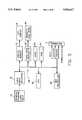
- FIG. 4is a block diagram of the major elements of the camera of FIG. 2;
- FIG. 5is a simplified block diagram of a typical PC-compatible computer
- FIG. 6is the pin-out diagram of the bus connector for a PC-compatible PC/XT bus
- FIG. 7shows the pin-out diagram of the bus connections which together with FIG. 6 make up a PC-compatible PC/AT bus
- FIG. 8is a more detailed diagram of the signal processor subsystem shown in FIG. 4;
- FIG. 9shows a second embodiment of the signal processor subsystem shown in FIG. 4.
- FIG. 10is a flow diagram of the image capture process.
- a camera module 2is shown attached to a bus connector 3 of a portable computer 4, which provides image processing, storage, and display.
- the bus connector 3is shown in broken line to indicate that it is hidden from view due to its location between the module 2 and the computer 4.
- the inventionis not limited to a particular computer, although a preferred computer is a small, battery operated IBM compatible personal computer (PC).
- PCIBM compatible personal computer
- One type of computer which is especially suitableis a "pen-based" computer, which is a small, portable unit that uses a pen-type stylus 6, rather than a keyboard and/or a "mouse” input device, for controlling the computer and inputting data. Menus are selected and data is entered using the stylus 6 to point to selections displayed on a pressure sensitive LCD display 8.
- Appropriate pen-based computersthat could be adapted for use with the invention include the NCR System 3000 Model 3125 NotePad computer manufactured by the NCR Corporation, Dayton, Ohio or the GridPad SL computer manufactured by Grid, a division of Tandy Corporation, Fort Worth, Tex. Both of these computers are compatible with the PC/AT bus (sometimes called the Industry Standard Architecture).
- the PC/AT bususes a compatible enhancement of the original PC bus, the PC/XT bus.
- the NCR 3125uses a CPU compatible with the Intel 386 microprocessor family, while the GridPad uses a CPU compatible with the Intel 8086 microprocessor family. Since the vast majority of personal computers in use today are compatible with the IBM PC/AT design, it is advantageous to design the camera module to connect to PC/AT compatible computers.
- the computer systemincludes optional "pod" attachments, which include electronics for specific applications.
- a rechargeable battery pack 10constitutes one pod
- the camera module 2constitutes a second pod.
- the camera module 2can be attached when needed for a particular application.
- the cameracaptures images and stores the images in the memory contained within the pen-based computer.
- other podsmay be attached, such as an RF transmitter pod (not shown) for allowing data to be transferred between the computer 4 and a central receiver (not shown).
- An exemplary imaging applicationis the automobile claims process, where there is a need to record data, including pictorial data, on vehicle damage in order to provide a repair estimate.
- the computer 4would store a set of claim forms, and the camera module 2 would be attached to the computer 4 to obtain still images which can immediately be incorporated into the forms, thereby creating "smart forms" including both images and the data needed for a particular application.
- a front 12 of the camera module 2includes a lens 14, which is covered with a flip-up flash 16 when not in use to protect the lens 14.
- a back 18 of the camera moduleincludes an optical viewfinder 20, which slides out of (or alternatively, flips away from) a recess 20a on the back 18 of the camera.
- the slide-out design for the viewfinder 20is advantageous because it takes up little room inside the camera module 2, and requires only a few optical elements.
- the camera module 2also includes a capture switch 22 (i.e., a "shutter button") for taking the picture.
- the camera module 2further includes an electrical interface connector 24 designed to mate with the bus connector 3 on the computer 4, thereby directly attaching the camera module 2 to the PC-compatible bus of the computer 4.
- the interface connector 24may be sufficiently sturdy to provide mechanical as well as electrical attachment.
- the camera module 2would be secured to the computer by means of screws 26 secured through the holes 26a to threaded holes (not shown) on the computer 4.
- FIG. 4shows the subsystems of the camera module 2.
- An optical system 28includes the lens 14, a diaphragm 34, a shutter 36, and an infrared blocking filter 38.
- the lens 14is fixed focus, and a close-up diopter lens 40 is optionally moved into the optical axis for close-up pictures.
- Image lightis directed by the optical system 28 upon an image sensor 42, which is a charge-coupled device (CCD) sensor, such as the full frame sensor KAF-400 manufactured by Eastman Kodak Company, Rochester, N.Y.
- CCDcharge-coupled device
- the sub-systems of the camera 20are controlled by a microprocessor 46.
- the exposure conditions of the imageare input to the microprocessor 46 from a photometer 48 and shutter release is initiated by the capture switch 22.
- the microprocessor 46instructs a pair of stepper drivers 50 to set the diaphragm 34 and to operate the shutter 36, and, as needed, to fire the flash 16.
- the microprocessor 46further interfaces with a signal processor 52, which controls the read-out clocking of the image sensor 42 and processes the image signal generated by the image sensor 42.
- the signal processor 52provides the processed image signals to the computer 4 via the bus-compatible electrical interface connector 24.
- FIG. 5A simplified block diagram of the computer 4, in particular, a PC-compatible computer, is shown in FIG. 5.
- the key component of the computeris the central processing unit, or CPU, 54.
- the CPUcan be, for example, a low power 16 bit CHMOS microprocessor such as the Intel 80C86A, manufactured by Intel Corp, Santa Clara, Calif.
- other processorsincluding CPUs compatible with the Intel 8088 CPU, Intel 80C286 CPU, or Intel 80386 or 80486 CPU families could be used.
- the CPU 54connects to a standardized, industry-compatible bus 58, which is a set of shared lines exchange of three types of digital signals: data signals, address signals, and control signals.
- the busWhen an 8086 or 8088 compatible processor is used, the bus is known as the PC/XT bus, which utilizes 54 signal lines and 8 power/ground lines, including eight bits of data and twenty bits of address.
- the bus 58When an 80286, 80386, or 80486 family CPU is used as the CPU in a "PC compatible" computer, the bus 58 is known as the PC/AT bus or ISA (Industry Standard Architecture) bus.
- the PC/AT busis an enhancement of the PC/XT bus.
- An additional connectorcarries an extra eight bits of data, four bits of address, and extra control lines.
- FIG. 6shows the 62 pin connector used in the PC/XT bus.
- the AT bususes both the connector shown in FIG. 6 and the connector shown in FIG. 7.
- the connector pin names for the PC/XT busare described in table 1, as follows.
- These pinsinclude power pins, which allow the plug-in board, and therefore the camera module 2, to be powered by the power supply (not shown) of the computer 4.
- the PC/AT connectorbesides additional data and address lines, includes additional interrupt request, direct memory access (DMA) request, DMA acknowledge, and other special lines for 16-bit control. Note that these standard connectors are not available on the outside of the case enclosing the computer 4. Instead, the case must be opened to insert the connector 24, which may be elongated for this purpose, into an empty slot in the computer bus 58.
- the data and address signalsare typically time multiplexed on the same microprocessor pins, and control lines indicate whether the signals on these pins contains an address or data.
- the control linesare used to latch the data and address signals onto the separate address and data bus lines of the signal bus 58.
- the control linescarry a group of "interrupt request" signals, which are used by peripherals when they need attention from the CPU 54.
- the address linesinclude two different address spaces known as memory address space and I/O address space.
- the most significant bit (MSB) address linesare typically used only for memory address space. Therefore, these MSBs can be used to represent different commands, when addressing a device using I/O address space.
- the PC-compatible bus 58is connected to both programmable read only memory (PROM) 60 and random access memory (RAM) 62.
- PROM 60stores the BIOS (Basic Input/Output System) portion of the PC operating system software.
- BIOSincludes the bootstrap loader, which is executed when the computer is first powered on.
- the rest of the PC operating systemis normally stored on a hard disk drive 64, which is connected to the bus 58 via a hard drive controller 66.
- the hard drive 64is also used to store application programs and data, including the digital images captured by the camera module 2. Portions of the disk operating system (DOS), application programs, and data are typically downloaded to the RAM memory 62 before program execution.
- DOSdisk operating system
- a direct memory access (DMA) controller 68is typically used to rapidly move data between the hard drive 64 and the RAM memory 62.
- the DMA controller 68transfers data between the memory address space and the I/O address space.
- the computer systemfurther includes the LCD display 8, which is normally connected to a display RAM memory 72 that is loaded by the CPU 54 via the bus 58, and at least one general purpose user input device 74, such as a keyboard, mouse, or the pen stylus 6.
- the user input device 74is connected to the bus 58 via a user input interface 76, which may include a separate microprocessor.
- the computer 4includes the PC-compatible bus connector 3, which is accessible from the outside of the computer case. By attaching the camera module 2 to the connector 3, the camera module 2 is able to access the PC-compatible bus 58 in order to transfer image data from the CCD imager 42 to the computer 4, and in general to allow the camera module 2 to be controlled using the general purpose user input 74.
- PC-compatible computersordinarily include internal "slots" with a standard bus connection, to allow users to purchase plug-in boards having additional memory, modems, etc., in order to expand the capabilities of their computer. This interface provides what is known as the "I/O bus?, or "I/O channel", using the standard connectors shown in FIGS. 6 and 7.
- the interface connector 124may include a plug-in extender board for inserting into the bus connection "slot" on the computer 4. (Although not specifically shown, the "slot" would enclose the connector 3 shown in FIG. 1.)
- the cameraincludes a 62 pin card edge connector and a 36 pin card edge connector, providing the connections shown in FIGS. 6 and 7, while the computer includes the appropriate female connectors accessible from the exterior of the case, to allow the camera module 2 to attach to the computer 4.
- the camera module 2is attached to the computer 4 using the screws 26.
- a plate(not shown) is screwed into the computer, to prevent the connector 3 from being abused.
- other types of physical connectorscan be used.
- the connectors 3 and 24may have fewer than 98 pins, since some of the bus signals may not be required by the camera.
- a logic circuit 80(such as Model EPS464 or Model EPM7096, integrated circuits manufactured by Altera Corp., San Jose, Calif.) provides the timing signals to control the image sensor 42 and the various parts of the signal processor 52.
- the logic circuit 80provides the horizontal and vertical clocking signals H1,H2,V1,V2 to read an image signal from the sensor 42 and the timing signal RESET to initiate each pixel read-out period.
- the output of the sensor 42is initially processed by an analog signal processor 82 incorporating, e.g., a gain stage and a correlated double sampling circuit, and converted to a digital signal by an analog-to-digital (A/D) converter 84.
- the digitized signalis then processed by an EPROM look-up table (LUT) 86 that stores the white balance and gamma correction curveshapes, and information about the camera.
- LUTEPROM look-up table
- the LUT 86can also store a camera serial number, location of sensor defects, the structure of a color filter array used on the sensor 42, color matrix coefficients optimized for a particular image sensor, etc. Moreover, the LUT 86 may also store the computer program which is used (by the computer) to operate the camera and to process the images from the sensor color filter array to obtain a full resolution, color corrected image. Such data is programmed into a portion of the EPROM memory 86, which is not used to provide the white balance and gamma correction look-up tables, when the camera module 2 is manufactured. The data is downloaded from the EPROM memory 86 in the camera module to the RAM memory 62 in the computer.
- a multiplexer 85is used to allow the computer to address the EPROM address least significant bit (LSB) lines which are normally provided by the A/D converter 84, while the timing logic 80 provides MSB address values which contain the required data, instead of the MSB values which provide the white balance and gamma correction curveshape tables.
- LSBleast significant bit
- the digitized signal processed by the LUT 86is then provided to two sets of octal latches, 88a, 88b, and 90a, 90b.
- Each octal latchstores one pixel value. While one set (88a, 88b or 90a, 90b) of latches is being loaded, the pixel values stored in the other set from the previous two pixels are read into the computer 4 through the 16-bit data lines D0-D15 on the bus-compatible connector 24.
- the camera module 2is controlled by signals generated by the computer 4 and applied to the address lines, which are decoded in an address decoder 92, and to the control lines of the bus 58.
- the operation of the image capture system of FIGS. 4, 5 and 8proceeds as shown in the flow chart of FIG. 10, in particular for a direct memory access (DMA) mode of operation.
- the userbegins by connecting the camera module 2 to the computer 4 via the connectors 3 and 24, and turns on the computer 4. This activates an application program.
- the userthen opens a "camera” application program by using the general purpose user input 74 and selects capture parameters from a menu displayed on the LCD display 8.
- a typical applicationmight utilize an electronic "smart form", which requires data to be entered via the LCD display 8 and the stylus 6, and which also requires a picture.
- the capture parametersmay include color (8, 16, or 24 bit) or monochrome (1 or 8 bit), full resolution or subsampled, and store direct to disk, compress before storing, or convert to a standard metric before storing. Therefore, depending on the capture parameters selected, the data is either stored directly from RAM 62 to the hard disk 64 (or other non-volatile computer memory), compressed before storage using conventional methods, or converted before storage to a full resolution color image.
- the userflips up the flash 16 and slides down the viewfinder 20. This closes a hidden switch (not shown) which powers up the camera.
- the camerausing the photometer 48, measures the ambient light level and charges the flash 16 if the ambient light level is low.
- the userframes the image using the optical viewfinder 20, and depresses the capture button 22. This begins a sequence which actuates the diaphragm 34, opens the shutter 36, fires the flash 16 if required, and closes the shutter 36.
- One line of the imageis then transferred from the vertical register of the CCD imager 42 to the horizontal readout register 42a.
- the timing logic 80generates a "line-ready" interrupt of the computer's CPU using a PC I/O bus interrupt line.
- the CPU 54instructs the DMA controller 68 to begin transfer of one line of data from the camera module 2 over the bus 58 to the computer's RAM memory 62.
- the DMA transferis controlled by the control line signals on the bus 58.
- the datais provided from the camera in groups of two 8 bit pixels at a time, to rapidly transfer the image from the CCD imager 42 to the computer RAM memory 62.
- the timing logic 80transfers another image line into the horizontal readout register 42a and then generates another "line-ready" interrupt.
- the camerasupplies data using only 8 bits out of the 16 data bits available on the PC/AT connector.
- a DRAM buffer memory 94capable of storing one entire image from the CCD imager 42, is inserted between the EPROM 86 and the interface connector 24 to substitute for the four octal latches in FIG. 8. This substitution lets the data transfer to the computer occur at any time following the image capture, without being synchronized to the sensor-readout. Such an unsynchronized transfer is useful in situations where the DMA transfer occurs at a slow enough rate that the "dark current" noise build-up in the sensor 42 would be too large.
- a status register 96is used instead of interrupt lines, to provide a status signal to the CPU 54 when an image has been captured and is ready to be transferred.
- This status register 96is a latch, controlled by the camera module timing logic 80, which is multiplexed onto the same data lines of the bus 58 as the image data.
- the address decoder 92directly passes the 2 LSBs of the PC bus address directly to the timing logic 80. These two LSBs provide various commands to the timing logic. For example, the computer can instruct the camera module to turn on the flash or to take a picture.
- the picture-taking sequencecould be initiated from the user input device 74 that is part of the computer 4, and the camera module 2 would then not require any user input device, such as the capture button 22.
- the camera module 2could be an integral part of the computer 4, i.e., the computer 4 would inherently include the capability of being a camera as well as a computer.
- the elements of the camera shown in FIG. 4, and the signal processor 52 shown further in FIGS. 8 and 9,would be additional parts of the PC-compatible computer shown in FIG. 5.
- the principal differencewould be that the PC bus-compatible connectors 3 and 24 would be replaced by a direct connection of the signal processor 52 to the signal bus 58.
Landscapes
- Engineering & Computer Science (AREA)
- Multimedia (AREA)
- Signal Processing (AREA)
- General Engineering & Computer Science (AREA)
- Computing Systems (AREA)
- Theoretical Computer Science (AREA)
- Human Computer Interaction (AREA)
- Physics & Mathematics (AREA)
- General Physics & Mathematics (AREA)
- Image Input (AREA)
Abstract
Description
TABLE 1 ______________________________________ IBM PC/XT BUS SIGNALS SIGNAL NAME PIN # FUNCTION ______________________________________ SA0-SA19 A31-A12 address (A0-A15 for I/O) SD0-SD7 A9-A2 data IOR B14 I/O read strobe IOW B13 I/O write strobe SMEMR B12 memory read strobe SMEMW B11 memory write strobe AEN A11 address enable IRQ2-IRQ7 B4, B25-B21 interrupt request RESET B2 power-on reset DRQ1-DRQ3 B18, B6, B16 DMA request DACK0-DACK3 B19, B17, B26, DMA acknowledge B15 BALE B28 address latch enable CLK B20 CPU clock I/O CH CK A1 I/O error I/O CH RDY A10 pull LOW for wait states OSC B30 oscillator (3 × CPU clk) T/C B27 DMA terminal count OWS B8 Zero wait state GND B1, B10, B31 signal & power gnd +5 V DC B3, B29 +5 V supply +12 V DC B9 +12 V supply -5 V DC B5 -5 V supply -12 V DC B7 -12 V supply ______________________________________
Claims (26)
Priority Applications (1)
| Application Number | Priority Date | Filing Date | Title |
|---|---|---|---|
| US07/988,560US5506617A (en) | 1992-12-10 | 1992-12-10 | Electronic camera incorporating a computer-compatible bus interface |
Applications Claiming Priority (1)
| Application Number | Priority Date | Filing Date | Title |
|---|---|---|---|
| US07/988,560US5506617A (en) | 1992-12-10 | 1992-12-10 | Electronic camera incorporating a computer-compatible bus interface |
Publications (1)
| Publication Number | Publication Date |
|---|---|
| US5506617Atrue US5506617A (en) | 1996-04-09 |
Family
ID=25534260
Family Applications (1)
| Application Number | Title | Priority Date | Filing Date |
|---|---|---|---|
| US07/988,560Expired - LifetimeUS5506617A (en) | 1992-12-10 | 1992-12-10 | Electronic camera incorporating a computer-compatible bus interface |
Country Status (1)
| Country | Link |
|---|---|
| US (1) | US5506617A (en) |
Cited By (76)
| Publication number | Priority date | Publication date | Assignee | Title |
|---|---|---|---|---|
| US5696850A (en)* | 1995-12-21 | 1997-12-09 | Eastman Kodak Company | Automatic image sharpening in an electronic imaging system |
| US5757431A (en)* | 1994-06-20 | 1998-05-26 | Lau Technologies | Apparatus for coupling multiple data sources onto a printed document |
| US5790274A (en)* | 1993-03-25 | 1998-08-04 | Hitachi, Ltd. | Imaging and recording apparatus |
| US5841471A (en)* | 1996-09-12 | 1998-11-24 | Eastman Kodak Company | Timing control for a digitally interfaced camera using variable line readout intervals |
| WO1998059490A1 (en)* | 1997-06-24 | 1998-12-30 | Cognex Corporation | Methods and apparatus for charge coupled device image acquisition with independent integration and readout |
| WO1999023817A1 (en)* | 1997-11-03 | 1999-05-14 | Intel Corporation | Dual mode digital camera for video and still operation |
| US5907359A (en)* | 1995-08-30 | 1999-05-25 | Sanyo Electric Co., Ltd. | Highly-integrated image sensing apparatus producing digitized output |
| WO1999035826A1 (en)* | 1998-01-07 | 1999-07-15 | Intel Corporation | Automatic transfer of image information between imaging device and host system |
| US5948086A (en)* | 1997-10-03 | 1999-09-07 | Inventec Corporation | Electronic still camera adapted for use in the battery receiving chamber of a portable computer |
| US5956087A (en)* | 1995-10-31 | 1999-09-21 | Canon Kabushiki Kaisha | Linear image sensor |
| WO1999048180A3 (en)* | 1998-03-16 | 1999-10-21 | Barnes Wentworth | Interface module and method for use in sending digitized data |
| US5991468A (en)* | 1995-08-03 | 1999-11-23 | Canon Kabushiki Kaisha | Card-type image sensor |
| US6075881A (en) | 1997-03-18 | 2000-06-13 | Cognex Corporation | Machine vision methods for identifying collinear sets of points from an image |
| WO1999064893A3 (en)* | 1998-06-08 | 2000-06-29 | Univ Brandeis | A low noise, high resolution image detection system and method |
| US6104430A (en)* | 1994-09-28 | 2000-08-15 | Ricoh Company, Ltd. | Digital electronic still camera which receives an input/output control program through a detachable communication interface card |
| US6111604A (en)* | 1995-02-21 | 2000-08-29 | Ricoh Company, Ltd. | Digital camera which detects a connection to an external device |
| US6118653A (en)* | 1997-06-03 | 2000-09-12 | Samsung Electronics Co., Ltd. | Camera mounting mechanism for supporting an electronic camera on a portable computer |
| EP0887991A3 (en)* | 1997-06-27 | 2001-01-10 | Canon Kabushiki Kaisha | I/O card, electronic equipment using I/O card, and procedure of starting up such electronic equipment |
| WO2001002905A1 (en)* | 1999-06-30 | 2001-01-11 | Silverbrook Research Pty Ltd | Digital camera with interactive printer |
| KR20010025054A (en)* | 1998-05-18 | 2001-03-26 | 피터 엔. 데트킨 | Method and apparatus to control the behavior of a digital camera by detecting connectivity to a universal serial bus |
| US6215901B1 (en)* | 1997-03-07 | 2001-04-10 | Mark H. Schwartz | Pen based computer handwriting instruction |
| US6219096B1 (en)* | 1995-04-28 | 2001-04-17 | Sony Corporation | Image signal generating and converting device |
| US6256059B1 (en)* | 1999-01-07 | 2001-07-03 | Intel Corporation | Automatic transfer of image information between imaging device and host system |
| US20010017656A1 (en)* | 2000-02-25 | 2001-08-30 | Asahi Kogaku Kogyo Kabushiki Kaisha | Internet camera system |
| US20010017655A1 (en)* | 2000-02-28 | 2001-08-30 | Asahi Kogaku Kogyo Kabushiki Kaisha | Internet camera |
| US6292272B1 (en) | 1995-08-03 | 2001-09-18 | Canon Kabushiki Kaisha | Image sensor |
| US20010024232A1 (en)* | 2000-02-18 | 2001-09-27 | Asahi Kogaku Kogyo Kabushiki Kaisha | Internet camera |
| US6330027B1 (en)* | 1995-08-08 | 2001-12-11 | Canon Kabushiki Kaisha | Video input apparatus with error recovery capability |
| US20020015020A1 (en)* | 2000-07-29 | 2002-02-07 | Farzad Mobin | Radio-style hollow appliance for interactive use with a computer |
| US6381366B1 (en) | 1998-12-18 | 2002-04-30 | Cognex Corporation | Machine vision methods and system for boundary point-based comparison of patterns and images |
| US6381375B1 (en) | 1998-02-20 | 2002-04-30 | Cognex Corporation | Methods and apparatus for generating a projection of an image |
| US20020053087A1 (en)* | 2000-10-27 | 2002-05-02 | Asahi Kogaku Kogyo Kabushiki Kaisha | Internet camera system |
| US6396949B1 (en) | 1996-03-21 | 2002-05-28 | Cognex Corporation | Machine vision methods for image segmentation using multiple images |
| US20020072935A1 (en)* | 2000-04-12 | 2002-06-13 | Rowse William T. | Method system and software for transmitting digital media between remote locations |
| US6429896B1 (en)* | 1996-02-21 | 2002-08-06 | Chinon Kabushiki Kaisha | Digital camera and external device for image storage and camera control |
| US20020149695A1 (en)* | 2001-04-12 | 2002-10-17 | Yasunobu Kayanuma | Cradle for information apparatus, cradle for digital camera and camera system |
| US6493025B1 (en)* | 1995-10-05 | 2002-12-10 | Sanyo Electronic Co., Ltd. | Image sensing system equipped with interface between image sensing apparatus and computer machinery |
| US20030002749A1 (en)* | 2001-06-28 | 2003-01-02 | Nokia Corporation, Espoo Finland | Method and apparatus for image improvement |
| US6587140B2 (en) | 1997-10-23 | 2003-07-01 | Eastman Kodak Company | System and method for using a single intelligence circuit in both a digital camera and printer |
| WO2003073184A1 (en)* | 2002-02-22 | 2003-09-04 | Concord Camera Corp. | Image capture device |
| US20030186708A1 (en)* | 2002-03-26 | 2003-10-02 | Parulski Kenneth A. | Portable imaging device employing geographic information to facilitate image access and viewing |
| US6650370B1 (en) | 1994-06-20 | 2003-11-18 | Viisage Technology, Inc. | Apparatus for coupling multiple data sources onto a printed document |
| US20030215143A1 (en)* | 2002-05-20 | 2003-11-20 | Zakrzewski Radoslaw Romuald | Viewing a compartment |
| US20030214583A1 (en)* | 2002-05-20 | 2003-11-20 | Mokhtar Sadok | Distinguishing between fire and non-fire conditions using cameras |
| US20030222889A1 (en)* | 2002-03-26 | 2003-12-04 | Kenneth Parulski | Portable imaging display device employing an aspect ratio dependent user interface control window |
| US6677989B1 (en) | 1993-03-25 | 2004-01-13 | Hitachi, Ltd. | Imaging and recording apparatus |
| US6684402B1 (en) | 1999-12-01 | 2004-01-27 | Cognex Technology And Investment Corporation | Control methods and apparatus for coupling multiple image acquisition devices to a digital data processor |
| US6687402B1 (en) | 1998-12-18 | 2004-02-03 | Cognex Corporation | Machine vision methods and systems for boundary feature comparison of patterns and images |
| US6690415B1 (en)* | 1996-12-10 | 2004-02-10 | Canon Kabushiki Kaisha | Camera, camera connecting device, and camera system |
| US20040049692A1 (en)* | 2002-06-18 | 2004-03-11 | Masayoshi Okamoto | Data transfer control system |
| US20040061777A1 (en)* | 2002-05-20 | 2004-04-01 | Mokhtar Sadok | Detecting fire using cameras |
| US6731952B2 (en) | 2000-07-27 | 2004-05-04 | Eastman Kodak Company | Mobile telephone system having a detachable camera / battery module |
| US6738090B2 (en) | 1997-10-23 | 2004-05-18 | Eastman Kodak Company | System and method for using a single intelligence circuit for a plurality of imaging rendering components |
| US6748104B1 (en) | 2000-03-24 | 2004-06-08 | Cognex Corporation | Methods and apparatus for machine vision inspection using single and multiple templates or patterns |
| US6784925B1 (en) | 1998-03-24 | 2004-08-31 | Canon Kabushiki Kaisha | System to manage digital camera images |
| US20040201693A1 (en)* | 2003-04-08 | 2004-10-14 | Canon Kabushiki Kaisha | Image processing system |
| US20050024509A1 (en)* | 1998-05-08 | 2005-02-03 | Itani Nadi R. | Histogram-based automatic gain control method and system for video applications |
| US20050052661A1 (en)* | 1999-06-30 | 2005-03-10 | Paul Lapstun | Cartridge with identifiers |
| US20050055727A1 (en)* | 1997-12-04 | 2005-03-10 | Pentax U.S.A., Inc. | Integrated internet/intranet camera |
| EP0969400A3 (en)* | 1998-06-30 | 2005-05-11 | Sony Corporation | Method for controlling a system comprising an Information processing apparatus and an image sensing device |
| US20050185090A1 (en)* | 2004-02-24 | 2005-08-25 | Purdy Michael L. | Handheld electronic device having a battery compartment door that includes a camera |
| EP1569067A1 (en)* | 2004-02-24 | 2005-08-31 | Research In Motion Limited | Handheld electronic device having a battery compartment door that includes a camera |
| US20050202804A1 (en)* | 1999-06-30 | 2005-09-15 | Silverbrook Research Pty Ltd | Method of using a mobile device to authenticate a printed token and output an image associated with the token |
| US20050219600A1 (en)* | 1999-06-30 | 2005-10-06 | Paul Lapstun | Cartridge with identifiers |
| US20060013630A1 (en)* | 1999-06-30 | 2006-01-19 | Silverbrook Research Pty Ltd | Printing a photograph using a mobile device |
| US20060025116A1 (en)* | 1999-06-30 | 2006-02-02 | Silverbrook Research Pty Ltd | Retrieving an image via a coded surface |
| US7006669B1 (en) | 2000-12-31 | 2006-02-28 | Cognex Corporation | Machine vision method and apparatus for thresholding images of non-uniform materials |
| US20070005823A1 (en)* | 1997-03-04 | 2007-01-04 | Papst Licensing Gmbh & Co. Kg | Analog Data Generating And Processing Device For Use With A Personal Computer |
| US20070081714A1 (en)* | 2005-10-07 | 2007-04-12 | Wallack Aaron S | Methods and apparatus for practical 3D vision system |
| US20070230950A1 (en)* | 2006-03-29 | 2007-10-04 | Altek Corporation | Image capture device |
| US20080050006A1 (en)* | 2006-08-23 | 2008-02-28 | Cognex Corporation | Method and apparatus for semiconductor wafer alignment |
| US7639861B2 (en) | 2005-09-14 | 2009-12-29 | Cognex Technology And Investment Corporation | Method and apparatus for backlighting a wafer during alignment |
| US8102457B1 (en) | 1997-07-09 | 2012-01-24 | Flashpoint Technology, Inc. | Method and apparatus for correcting aspect ratio in a camera graphical user interface |
| US8127232B2 (en) | 1998-12-31 | 2012-02-28 | Flashpoint Technology, Inc. | Method and apparatus for editing heterogeneous media objects in a digital imaging device |
| US8736694B2 (en) | 1995-04-24 | 2014-05-27 | Intellectual Ventures Fund 83 Llc | Transmitting digital images to a plurality of selected receivers over a radio frequency link |
| US9224145B1 (en) | 2006-08-30 | 2015-12-29 | Qurio Holdings, Inc. | Venue based digital rights using capture device with digital watermarking capability |
Citations (8)
| Publication number | Priority date | Publication date | Assignee | Title |
|---|---|---|---|---|
| US4425586A (en)* | 1981-03-13 | 1984-01-10 | Miller Richard L | Apparatus and method for storing and interrelating visual data and computer information |
| US4545068A (en)* | 1982-02-10 | 1985-10-01 | Tokyo Shibaura Denki Kabushiki Kaisha | Image processing system |
| US4587633A (en)* | 1982-11-10 | 1986-05-06 | Wang Laboratories, Inc. | Management communication terminal system |
| US4589020A (en)* | 1982-11-22 | 1986-05-13 | Olympus Optical Co., Ltd. | TV video data input apparatus |
| US5138459A (en)* | 1990-11-20 | 1992-08-11 | Personal Computer Cameras, Inc. | Electronic still video camera with direct personal computer (pc) compatible digital format output |
| US5182647A (en)* | 1990-12-13 | 1993-01-26 | Eastman Kodak Company | High resolution charge-coupled device (ccd) camera system |
| US5231501A (en)* | 1989-05-25 | 1993-07-27 | Asahi Kogaku Kogyo Kabushiki Kaisha | Still video apparatus |
| US5258859A (en)* | 1989-07-25 | 1993-11-02 | Minolta Camera Kabushiki Kaisha | Image reproducing system |
- 1992
- 1992-12-10USUS07/988,560patent/US5506617A/ennot_activeExpired - Lifetime
Patent Citations (8)
| Publication number | Priority date | Publication date | Assignee | Title |
|---|---|---|---|---|
| US4425586A (en)* | 1981-03-13 | 1984-01-10 | Miller Richard L | Apparatus and method for storing and interrelating visual data and computer information |
| US4545068A (en)* | 1982-02-10 | 1985-10-01 | Tokyo Shibaura Denki Kabushiki Kaisha | Image processing system |
| US4587633A (en)* | 1982-11-10 | 1986-05-06 | Wang Laboratories, Inc. | Management communication terminal system |
| US4589020A (en)* | 1982-11-22 | 1986-05-13 | Olympus Optical Co., Ltd. | TV video data input apparatus |
| US5231501A (en)* | 1989-05-25 | 1993-07-27 | Asahi Kogaku Kogyo Kabushiki Kaisha | Still video apparatus |
| US5258859A (en)* | 1989-07-25 | 1993-11-02 | Minolta Camera Kabushiki Kaisha | Image reproducing system |
| US5138459A (en)* | 1990-11-20 | 1992-08-11 | Personal Computer Cameras, Inc. | Electronic still video camera with direct personal computer (pc) compatible digital format output |
| US5182647A (en)* | 1990-12-13 | 1993-01-26 | Eastman Kodak Company | High resolution charge-coupled device (ccd) camera system |
Cited By (184)
| Publication number | Priority date | Publication date | Assignee | Title |
|---|---|---|---|---|
| US7304669B2 (en) | 1993-03-25 | 2007-12-04 | Hitachi, Ltd. | Imaging and recording apparatus |
| US6677989B1 (en) | 1993-03-25 | 2004-01-13 | Hitachi, Ltd. | Imaging and recording apparatus |
| US5790274A (en)* | 1993-03-25 | 1998-08-04 | Hitachi, Ltd. | Imaging and recording apparatus |
| US5793517A (en)* | 1993-03-25 | 1998-08-11 | Hitachi, Ltd. | Imaging and recording apparatus |
| US5801847A (en)* | 1993-03-25 | 1998-09-01 | Hitachi, Ltd. | Imaging and recording apparatus |
| US8314858B2 (en) | 1993-03-25 | 2012-11-20 | Samsung Electronics Co., Ltd. | Imaging and recording apparatus controlling erasure of data in flash type memory |
| US20040135901A1 (en)* | 1993-03-25 | 2004-07-15 | Iwao Aizawa | Imaging and recording apparatus |
| US6081350A (en)* | 1993-03-25 | 2000-06-27 | Hitachi, Ltd. | Imaging and recording apparatus |
| US20080084485A1 (en)* | 1993-03-25 | 2008-04-10 | Iwao Aizawa | Imaging And Recording Apparatus |
| US6650370B1 (en) | 1994-06-20 | 2003-11-18 | Viisage Technology, Inc. | Apparatus for coupling multiple data sources onto a printed document |
| US5757431A (en)* | 1994-06-20 | 1998-05-26 | Lau Technologies | Apparatus for coupling multiple data sources onto a printed document |
| US7432952B2 (en) | 1994-09-28 | 2008-10-07 | Ricoh Company, Ltd. | Digital image capturing device having an interface for receiving a control program |
| US20020054212A1 (en)* | 1994-09-28 | 2002-05-09 | Hiroki Fukuoka | Digital electronic still camera which receives an input/output control program through a detachable communication interface card |
| US6104430A (en)* | 1994-09-28 | 2000-08-15 | Ricoh Company, Ltd. | Digital electronic still camera which receives an input/output control program through a detachable communication interface card |
| US20100321508A1 (en)* | 1995-02-21 | 2010-12-23 | Tetsuya Hashimoto | Digital camera which detects a connection to an external device |
| US7046276B2 (en) | 1995-02-21 | 2006-05-16 | Ricoh Company, Ltd. | Digital camera with external connection detection and mode switching capabilities |
| US20020089592A1 (en)* | 1995-02-21 | 2002-07-11 | Tetsuya Hashimoto | Digital camera which detects a connection to an external device |
| US20060158528A1 (en)* | 1995-02-21 | 2006-07-20 | Tetsuya Hashimoto | Digital camera which detects a connection to an external device |
| US7889240B2 (en) | 1995-02-21 | 2011-02-15 | Ricoh Company, Ltd. | Digital camera which detects a connection to an external device |
| US6111604A (en)* | 1995-02-21 | 2000-08-29 | Ricoh Company, Ltd. | Digital camera which detects a connection to an external device |
| US9256280B2 (en) | 1995-02-21 | 2016-02-09 | Ricoh Company, Ltd. | Digital camera which detects a connection to an external device |
| US8525891B2 (en) | 1995-02-21 | 2013-09-03 | Ricoh Company, Ltd. | Digital camera which detects a connection to an external device |
| US8736694B2 (en) | 1995-04-24 | 2014-05-27 | Intellectual Ventures Fund 83 Llc | Transmitting digital images to a plurality of selected receivers over a radio frequency link |
| US6219096B1 (en)* | 1995-04-28 | 2001-04-17 | Sony Corporation | Image signal generating and converting device |
| US6292272B1 (en) | 1995-08-03 | 2001-09-18 | Canon Kabushiki Kaisha | Image sensor |
| US5991468A (en)* | 1995-08-03 | 1999-11-23 | Canon Kabushiki Kaisha | Card-type image sensor |
| US6330027B1 (en)* | 1995-08-08 | 2001-12-11 | Canon Kabushiki Kaisha | Video input apparatus with error recovery capability |
| US5907359A (en)* | 1995-08-30 | 1999-05-25 | Sanyo Electric Co., Ltd. | Highly-integrated image sensing apparatus producing digitized output |
| US6493025B1 (en)* | 1995-10-05 | 2002-12-10 | Sanyo Electronic Co., Ltd. | Image sensing system equipped with interface between image sensing apparatus and computer machinery |
| US5956087A (en)* | 1995-10-31 | 1999-09-21 | Canon Kabushiki Kaisha | Linear image sensor |
| US5696850A (en)* | 1995-12-21 | 1997-12-09 | Eastman Kodak Company | Automatic image sharpening in an electronic imaging system |
| US6429896B1 (en)* | 1996-02-21 | 2002-08-06 | Chinon Kabushiki Kaisha | Digital camera and external device for image storage and camera control |
| US6396949B1 (en) | 1996-03-21 | 2002-05-28 | Cognex Corporation | Machine vision methods for image segmentation using multiple images |
| US5841471A (en)* | 1996-09-12 | 1998-11-24 | Eastman Kodak Company | Timing control for a digitally interfaced camera using variable line readout intervals |
| US6690415B1 (en)* | 1996-12-10 | 2004-02-10 | Canon Kabushiki Kaisha | Camera, camera connecting device, and camera system |
| US20070005823A1 (en)* | 1997-03-04 | 2007-01-04 | Papst Licensing Gmbh & Co. Kg | Analog Data Generating And Processing Device For Use With A Personal Computer |
| US8966144B2 (en) | 1997-03-04 | 2015-02-24 | Papst Licensing Gmbh & Co. Kg | Analog data generating and processing device having a multi-use automatic processor |
| US9189437B2 (en) | 1997-03-04 | 2015-11-17 | Papst Licensing Gmbh & Co. Kg | Analog data generating and processing device having a multi-use automatic processor |
| US8504746B2 (en) | 1997-03-04 | 2013-08-06 | Papst Licensing Gmbh & Co. Kg | Analog data generating and processing device for use with a personal computer |
| US20110131353A1 (en)* | 1997-03-04 | 2011-06-02 | Papst Licensing Gmbh & Co. Kg | Analog data generating and processing device for use with a personal computer |
| US6215901B1 (en)* | 1997-03-07 | 2001-04-10 | Mark H. Schwartz | Pen based computer handwriting instruction |
| US6075881A (en) | 1997-03-18 | 2000-06-13 | Cognex Corporation | Machine vision methods for identifying collinear sets of points from an image |
| US6118653A (en)* | 1997-06-03 | 2000-09-12 | Samsung Electronics Co., Ltd. | Camera mounting mechanism for supporting an electronic camera on a portable computer |
| WO1998059490A1 (en)* | 1997-06-24 | 1998-12-30 | Cognex Corporation | Methods and apparatus for charge coupled device image acquisition with independent integration and readout |
| US6608647B1 (en) | 1997-06-24 | 2003-08-19 | Cognex Corporation | Methods and apparatus for charge coupled device image acquisition with independent integration and readout |
| EP0887991A3 (en)* | 1997-06-27 | 2001-01-10 | Canon Kabushiki Kaisha | I/O card, electronic equipment using I/O card, and procedure of starting up such electronic equipment |
| US8102457B1 (en) | 1997-07-09 | 2012-01-24 | Flashpoint Technology, Inc. | Method and apparatus for correcting aspect ratio in a camera graphical user interface |
| US8970761B2 (en) | 1997-07-09 | 2015-03-03 | Flashpoint Technology, Inc. | Method and apparatus for correcting aspect ratio in a camera graphical user interface |
| US5948086A (en)* | 1997-10-03 | 1999-09-07 | Inventec Corporation | Electronic still camera adapted for use in the battery receiving chamber of a portable computer |
| US6587140B2 (en) | 1997-10-23 | 2003-07-01 | Eastman Kodak Company | System and method for using a single intelligence circuit in both a digital camera and printer |
| US6747689B1 (en) | 1997-10-23 | 2004-06-08 | Eastman Kodak Company | Method of operating a multiple component electronic imaging system |
| US6738090B2 (en) | 1997-10-23 | 2004-05-18 | Eastman Kodak Company | System and method for using a single intelligence circuit for a plurality of imaging rendering components |
| US6556242B1 (en) | 1997-11-03 | 2003-04-29 | Intel Corporation | Dual mode signal processing system for video and still image data |
| WO1999023817A1 (en)* | 1997-11-03 | 1999-05-14 | Intel Corporation | Dual mode digital camera for video and still operation |
| US6151069A (en)* | 1997-11-03 | 2000-11-21 | Intel Corporation | Dual mode digital camera for video and still operation |
| GB2346756A (en)* | 1997-11-03 | 2000-08-16 | Intel Corp | Dual mode digital camera for video and still operation |
| US7640567B2 (en) | 1997-12-04 | 2009-12-29 | Pentax Of America, Inc. | Camera connectible to CCTV network |
| US20060031902A1 (en)* | 1997-12-04 | 2006-02-09 | Pentax Of America, Inc. | Integrated internet camera |
| US9621778B2 (en) | 1997-12-04 | 2017-04-11 | Axis Ab | Device for sending image data from camera to CCTV network |
| US7272845B2 (en) | 1997-12-04 | 2007-09-18 | Pentax Of America, Inc. | Integrated internet/intranet camera |
| US20070288974A1 (en)* | 1997-12-04 | 2007-12-13 | Pentax Of America, Inc. | Integrated internet camera |
| US7350224B2 (en) | 1997-12-04 | 2008-03-25 | Pentax Of America, Inc. | Integrated internet/intranet camera |
| US9143672B2 (en) | 1997-12-04 | 2015-09-22 | Axis Ab | Device for sending image data from camera to CCTV network |
| US7425987B2 (en) | 1997-12-04 | 2008-09-16 | Pentax Of America, Inc. | Method of transmitting image data from standalone device |
| US7428005B2 (en) | 1997-12-04 | 2008-09-23 | Pentax Of America, Inc. | Integrated Internet/intranet camera |
| US7428004B2 (en) | 1997-12-04 | 2008-09-23 | Pentax Of America, Inc. | Standalone device connectible to CCTV network |
| US7523480B2 (en) | 1997-12-04 | 2009-04-21 | Pentax Of America, Inc. | Integrated Internet camera |
| US7523481B2 (en) | 1997-12-04 | 2009-04-21 | Pentax Of America, Inc. | Integrated internet camera |
| US20070268373A1 (en)* | 1997-12-04 | 2007-11-22 | Pentax Of America, Inc. | Integrated internet camera |
| US20060031901A1 (en)* | 1997-12-04 | 2006-02-09 | Pentax Of America, Inc. | Integrated internet camera |
| US7631335B2 (en) | 1997-12-04 | 2009-12-08 | Pentax Of America, Inc. | Integrated internet camera |
| US7640568B2 (en) | 1997-12-04 | 2009-12-29 | Pentax Of America, Inc. | Integrated internet camera |
| US8381255B2 (en) | 1997-12-04 | 2013-02-19 | Axis Ab | Device for sending image data from camera to CCTV network |
| US7644431B2 (en) | 1997-12-04 | 2010-01-05 | Pentax Of America, Inc. | Method for sending image data from camera to CCTV network |
| US20100023981A1 (en)* | 1997-12-04 | 2010-01-28 | Pentax Of America, Inc. | Method for sending image data from camera to cctv network |
| US20050055727A1 (en)* | 1997-12-04 | 2005-03-10 | Pentax U.S.A., Inc. | Integrated internet/intranet camera |
| US20100023982A1 (en)* | 1997-12-04 | 2010-01-28 | Pentax Of America, Inc. | Camera connectible to cctv network |
| US7962946B2 (en) | 1997-12-04 | 2011-06-14 | Axis Ab | Camera connectible to CCTV network |
| US20050099519A1 (en)* | 1997-12-04 | 2005-05-12 | Pentax U.S.A., Inc. | Integrated internet camera |
| US20050144653A1 (en)* | 1997-12-04 | 2005-06-30 | Pentax U.S.A., Inc. | Method of transmitting image data from standalone device |
| US20110197241A1 (en)* | 1997-12-04 | 2011-08-11 | Axis Ab | Device for sending image data from camera to cctv network |
| US20050146610A1 (en)* | 1997-12-04 | 2005-07-07 | Pentax U.S.A., Inc. | Camera connectible to CCTV network |
| US20050146609A1 (en)* | 1997-12-04 | 2005-07-07 | Pentax U.S.A., Inc. | Method for sending image data from camera to CCTV network |
| US20050149979A1 (en)* | 1997-12-04 | 2005-07-07 | Pentax U.S.A., Inc. | Standalone device connectible to CCTV network |
| US7962945B2 (en) | 1997-12-04 | 2011-06-14 | Axis Ab | Method for sending image data from camera to cctv network |
| WO1999035826A1 (en)* | 1998-01-07 | 1999-07-15 | Intel Corporation | Automatic transfer of image information between imaging device and host system |
| US20010015758A1 (en)* | 1998-01-07 | 2001-08-23 | Fichtner Mark R. | Automatic transfer of image information between imaging device and host system |
| US7170551B2 (en) | 1998-01-07 | 2007-01-30 | Intel Corporation | Automatic transfer of image information between imaging device and host system |
| GB2347576A (en)* | 1998-01-07 | 2000-09-06 | Intel Corp | Automatic transfer of image information between imaging device and host system |
| GB2347576B (en)* | 1998-01-07 | 2002-07-10 | Intel Corp | Automatic transfer of image information between imaging device and host system |
| US6381375B1 (en) | 1998-02-20 | 2002-04-30 | Cognex Corporation | Methods and apparatus for generating a projection of an image |
| WO1999048180A3 (en)* | 1998-03-16 | 1999-10-21 | Barnes Wentworth | Interface module and method for use in sending digitized data |
| US8810660B2 (en) | 1998-03-24 | 2014-08-19 | Canon Kabushiki Kaisha | System to manage digital camera images |
| US20040179115A1 (en)* | 1998-03-24 | 2004-09-16 | Canon Kabushiki Kaisha | System to manage digital camera images |
| US6784925B1 (en) | 1998-03-24 | 2004-08-31 | Canon Kabushiki Kaisha | System to manage digital camera images |
| US20090207254A1 (en)* | 1998-03-24 | 2009-08-20 | Canon Kabushiki Kaisha | System to manage digital camera images |
| US8736712B2 (en) | 1998-03-24 | 2014-05-27 | Canon Kabushiki Kaisha | System to manage digital camera images |
| US7522193B2 (en)* | 1998-05-08 | 2009-04-21 | Cirrus Logic, Inc. | Histogram-based automatic gain control method and system for video applications |
| US20050024509A1 (en)* | 1998-05-08 | 2005-02-03 | Itani Nadi R. | Histogram-based automatic gain control method and system for video applications |
| KR20010025054A (en)* | 1998-05-18 | 2001-03-26 | 피터 엔. 데트킨 | Method and apparatus to control the behavior of a digital camera by detecting connectivity to a universal serial bus |
| WO1999064893A3 (en)* | 1998-06-08 | 2000-06-29 | Univ Brandeis | A low noise, high resolution image detection system and method |
| EP0969400A3 (en)* | 1998-06-30 | 2005-05-11 | Sony Corporation | Method for controlling a system comprising an Information processing apparatus and an image sensing device |
| US6381366B1 (en) | 1998-12-18 | 2002-04-30 | Cognex Corporation | Machine vision methods and system for boundary point-based comparison of patterns and images |
| US6687402B1 (en) | 1998-12-18 | 2004-02-03 | Cognex Corporation | Machine vision methods and systems for boundary feature comparison of patterns and images |
| US8972867B1 (en) | 1998-12-31 | 2015-03-03 | Flashpoint Technology, Inc. | Method and apparatus for editing heterogeneous media objects in a digital imaging device |
| US8127232B2 (en) | 1998-12-31 | 2012-02-28 | Flashpoint Technology, Inc. | Method and apparatus for editing heterogeneous media objects in a digital imaging device |
| US6256059B1 (en)* | 1999-01-07 | 2001-07-03 | Intel Corporation | Automatic transfer of image information between imaging device and host system |
| US7834906B2 (en) | 1999-06-30 | 2010-11-16 | Silverbrook Research Pty Ltd | Camera having printer for printing interactive interfaces |
| US8218195B2 (en) | 1999-06-30 | 2012-07-10 | Silverbrook Research Pty Ltd | Cartridge for use in printer for printing coded data |
| WO2001002905A1 (en)* | 1999-06-30 | 2001-01-11 | Silverbrook Research Pty Ltd | Digital camera with interactive printer |
| AU761354B2 (en)* | 1999-06-30 | 2003-06-05 | Silverbrook Research Pty Ltd | Digital camera with interactive printer |
| US6831682B1 (en) | 1999-06-30 | 2004-12-14 | Silverbrook Research Pty Ltd | Digital camera with interactive printer |
| US8351907B2 (en) | 1999-06-30 | 2013-01-08 | Silverbrook Research Pty Ltd | Retrieving a document using a print medium having encoded print medium identifier |
| US20050052661A1 (en)* | 1999-06-30 | 2005-03-10 | Paul Lapstun | Cartridge with identifiers |
| US8274569B2 (en) | 1999-06-30 | 2012-09-25 | Silverbrook Research Pty Ltd | Printing system utilizing cartridge pre-stored with identifiers with identifying printed pages |
| US20050062851A1 (en)* | 1999-06-30 | 2005-03-24 | Kia Silverbrook | Digital camera with interactive printer |
| US8009196B2 (en) | 1999-06-30 | 2011-08-30 | Silverbrook Research Pty Ltd | Camera having networked interactive printer |
| US20050146615A1 (en)* | 1999-06-30 | 2005-07-07 | Kia Silverbrook | Digital camera with interactive printer |
| KR100716035B1 (en)* | 1999-06-30 | 2007-05-08 | 실버브룩 리서치 피티와이 리미티드 | Digital camera with interactive printer |
| US7920166B2 (en) | 1999-06-30 | 2011-04-05 | Silverbrook Research Pty Ltd | Camera having coded data interactive printer |
| US20110069354A1 (en)* | 1999-06-30 | 2011-03-24 | Silverbrook Research Pty Ltd | Printing system utilizing cartridge pre-stored with identifiers with identifying printed pages |
| US20100328701A1 (en)* | 1999-06-30 | 2010-12-30 | Silverbrook Research Pty Ltd. | Performing an Action Using a Printed Medium |
| US7831244B2 (en) | 1999-06-30 | 2010-11-09 | Silverbrook Research Pty Ltd | Retrieving an image via a coded surface |
| US20080252735A1 (en)* | 1999-06-30 | 2008-10-16 | Silverbrook Research Pty Ltd | Camera having printer for printing interactive interfaces |
| US20080259166A1 (en)* | 1999-06-30 | 2008-10-23 | Silverbrook Research Pty Ltd | Camera having networked interactive printer |
| US20080259165A1 (en)* | 1999-06-30 | 2008-10-23 | Silverbrook Research Pty Ltd | Camera having printer for printing interactive interfaces |
| US7817989B2 (en) | 1999-06-30 | 2010-10-19 | Silverbrook Research Pty Ltd | Method of performing an action using a printed medium |
| US7792298B2 (en) | 1999-06-30 | 2010-09-07 | Silverbrook Research Pty Ltd | Method of using a mobile device to authenticate a printed token and output an image associated with the token |
| US20100135679A1 (en)* | 1999-06-30 | 2010-06-03 | Silverbrook Research Pty Ltd | Cartridge for use in printer for printing coded data |
| US7728872B2 (en) | 1999-06-30 | 2010-06-01 | Silverbrook Research Pty Ltd | Digital camera with interactive printer |
| US7538793B2 (en) | 1999-06-30 | 2009-05-26 | Silverbrook Research Pty Ltd | Digital camera with interactive printer |
| US20100060744A1 (en)* | 1999-06-30 | 2010-03-11 | Silverbrook Research Pty Ltd | Camera For Capturing And Printing Images |
| US20100046030A1 (en)* | 1999-06-30 | 2010-02-25 | Silverbrook Research Pty Ltd | Method of Performing an Action Using a Printed Medium |
| US20090231443A1 (en)* | 1999-06-30 | 2009-09-17 | Silverbrook Research Pty Ltd | Camera having networked printer |
| US20060025116A1 (en)* | 1999-06-30 | 2006-02-02 | Silverbrook Research Pty Ltd | Retrieving an image via a coded surface |
| CN100573438C (en)* | 1999-06-30 | 2009-12-23 | 西尔弗布鲁克研究股份有限公司 | Digital camera with interactive printer |
| US7663780B2 (en) | 1999-06-30 | 2010-02-16 | Silverbrook Research Pty Ltd | Cartridge with identifiers |
| US20060013630A1 (en)* | 1999-06-30 | 2006-01-19 | Silverbrook Research Pty Ltd | Printing a photograph using a mobile device |
| US20050202804A1 (en)* | 1999-06-30 | 2005-09-15 | Silverbrook Research Pty Ltd | Method of using a mobile device to authenticate a printed token and output an image associated with the token |
| US20050219600A1 (en)* | 1999-06-30 | 2005-10-06 | Paul Lapstun | Cartridge with identifiers |
| US6684402B1 (en) | 1999-12-01 | 2004-01-27 | Cognex Technology And Investment Corporation | Control methods and apparatus for coupling multiple image acquisition devices to a digital data processor |
| US6980232B2 (en) | 2000-02-18 | 2005-12-27 | Pentax Corporation | Image transmitting Internet camera |
| US20010024232A1 (en)* | 2000-02-18 | 2001-09-27 | Asahi Kogaku Kogyo Kabushiki Kaisha | Internet camera |
| US20010017656A1 (en)* | 2000-02-25 | 2001-08-30 | Asahi Kogaku Kogyo Kabushiki Kaisha | Internet camera system |
| US6965398B2 (en) | 2000-02-28 | 2005-11-15 | Pentax Corporation | Internet camera |
| US20010017655A1 (en)* | 2000-02-28 | 2001-08-30 | Asahi Kogaku Kogyo Kabushiki Kaisha | Internet camera |
| US6748104B1 (en) | 2000-03-24 | 2004-06-08 | Cognex Corporation | Methods and apparatus for machine vision inspection using single and multiple templates or patterns |
| US20020072935A1 (en)* | 2000-04-12 | 2002-06-13 | Rowse William T. | Method system and software for transmitting digital media between remote locations |
| US6731952B2 (en) | 2000-07-27 | 2004-05-04 | Eastman Kodak Company | Mobile telephone system having a detachable camera / battery module |
| US20020015020A1 (en)* | 2000-07-29 | 2002-02-07 | Farzad Mobin | Radio-style hollow appliance for interactive use with a computer |
| US7562380B2 (en) | 2000-10-27 | 2009-07-14 | Hoya Corporation | Internet camera system |
| US20020053087A1 (en)* | 2000-10-27 | 2002-05-02 | Asahi Kogaku Kogyo Kabushiki Kaisha | Internet camera system |
| US7006669B1 (en) | 2000-12-31 | 2006-02-28 | Cognex Corporation | Machine vision method and apparatus for thresholding images of non-uniform materials |
| US20070015550A1 (en)* | 2001-04-12 | 2007-01-18 | Yasunobu Kayanuma | Cradle for information apparatus, cradle for digital camera and camera system |
| US7167206B2 (en)* | 2001-04-12 | 2007-01-23 | Fuji Photo Film Co., Ltd. | Cradle for information apparatus, cradle for digital camera and camera system |
| US20020149695A1 (en)* | 2001-04-12 | 2002-10-17 | Yasunobu Kayanuma | Cradle for information apparatus, cradle for digital camera and camera system |
| US20080303926A1 (en)* | 2001-06-28 | 2008-12-11 | Nokia Corporation | Method and apparatus for image improvement |
| US7426316B2 (en)* | 2001-06-28 | 2008-09-16 | Nokia Corporation | Method and apparatus for image improvement |
| US8103123B2 (en) | 2001-06-28 | 2012-01-24 | Nokia Corporation | Method and apparatus for image improvement |
| US20030002749A1 (en)* | 2001-06-28 | 2003-01-02 | Nokia Corporation, Espoo Finland | Method and apparatus for image improvement |
| WO2003073184A1 (en)* | 2002-02-22 | 2003-09-04 | Concord Camera Corp. | Image capture device |
| US20030186708A1 (en)* | 2002-03-26 | 2003-10-02 | Parulski Kenneth A. | Portable imaging device employing geographic information to facilitate image access and viewing |
| US7146179B2 (en) | 2002-03-26 | 2006-12-05 | Parulski Kenneth A | Portable imaging device employing geographic information to facilitate image access and viewing |
| US20030222889A1 (en)* | 2002-03-26 | 2003-12-04 | Kenneth Parulski | Portable imaging display device employing an aspect ratio dependent user interface control window |
| US7280696B2 (en) | 2002-05-20 | 2007-10-09 | Simmonds Precision Products, Inc. | Video detection/verification system |
| US20030215143A1 (en)* | 2002-05-20 | 2003-11-20 | Zakrzewski Radoslaw Romuald | Viewing a compartment |
| US7245315B2 (en) | 2002-05-20 | 2007-07-17 | Simmonds Precision Products, Inc. | Distinguishing between fire and non-fire conditions using cameras |
| US20030214583A1 (en)* | 2002-05-20 | 2003-11-20 | Mokhtar Sadok | Distinguishing between fire and non-fire conditions using cameras |
| US7256818B2 (en) | 2002-05-20 | 2007-08-14 | Simmonds Precision Products, Inc. | Detecting fire using cameras |
| US20040061777A1 (en)* | 2002-05-20 | 2004-04-01 | Mokhtar Sadok | Detecting fire using cameras |
| US7302101B2 (en) | 2002-05-20 | 2007-11-27 | Simmonds Precision Products, Inc. | Viewing a compartment |
| US20040049692A1 (en)* | 2002-06-18 | 2004-03-11 | Masayoshi Okamoto | Data transfer control system |
| US7418601B2 (en)* | 2002-06-18 | 2008-08-26 | Sanyo Electric Co., Ltd. | Data transfer control system |
| US20040201693A1 (en)* | 2003-04-08 | 2004-10-14 | Canon Kabushiki Kaisha | Image processing system |
| US20050185090A1 (en)* | 2004-02-24 | 2005-08-25 | Purdy Michael L. | Handheld electronic device having a battery compartment door that includes a camera |
| EP1569067A1 (en)* | 2004-02-24 | 2005-08-31 | Research In Motion Limited | Handheld electronic device having a battery compartment door that includes a camera |
| US7330216B2 (en) | 2004-02-24 | 2008-02-12 | Research In Motion Limited | Handheld electronic device having a battery compartment door that includes a camera |
| US7639861B2 (en) | 2005-09-14 | 2009-12-29 | Cognex Technology And Investment Corporation | Method and apparatus for backlighting a wafer during alignment |
| US20070081714A1 (en)* | 2005-10-07 | 2007-04-12 | Wallack Aaron S | Methods and apparatus for practical 3D vision system |
| US8111904B2 (en) | 2005-10-07 | 2012-02-07 | Cognex Technology And Investment Corp. | Methods and apparatus for practical 3D vision system |
| US20070230950A1 (en)* | 2006-03-29 | 2007-10-04 | Altek Corporation | Image capture device |
| US8162584B2 (en) | 2006-08-23 | 2012-04-24 | Cognex Corporation | Method and apparatus for semiconductor wafer alignment |
| US20080050006A1 (en)* | 2006-08-23 | 2008-02-28 | Cognex Corporation | Method and apparatus for semiconductor wafer alignment |
| US9224145B1 (en) | 2006-08-30 | 2015-12-29 | Qurio Holdings, Inc. | Venue based digital rights using capture device with digital watermarking capability |
Similar Documents
| Publication | Publication Date | Title |
|---|---|---|
| US5506617A (en) | Electronic camera incorporating a computer-compatible bus interface | |
| US5475441A (en) | Electronic camera with memory card interface to a computer | |
| US7023467B2 (en) | Photocard that is inserted into a non-digital camera to enable the non-digital camera to take digital photographic images | |
| US6181883B1 (en) | Dual purpose camera for VSC with conventional film and digital image capture modules | |
| US5790193A (en) | Accessory module for an electronic camera | |
| EP0669752B1 (en) | Intelligent digital image storage for an electronic camera | |
| US5040068A (en) | Electronic imaging apparatus with interchangeable pickup units | |
| US5748339A (en) | Image sensing apparatus | |
| US7095442B2 (en) | Method and apparatus for capturing an image | |
| US6608650B1 (en) | Interactive assistant process for aiding a user in camera setup and operation | |
| US6833867B1 (en) | Method and system for expanding the hardware capabilities of a digital imaging device | |
| JPH1065947A (en) | Digital camera | |
| US20050162711A1 (en) | Digital picture frame with picture acquisition | |
| WO2000007499A1 (en) | Filmless dental radiography system using universal serial bus port | |
| JPH07240871A (en) | Portable type electron camera giving optional parameter to be set from computor | |
| US6400471B1 (en) | Flexible architecture for image processing | |
| EP0522132A1 (en) | Memoryless electronic camera with direct hard copy output | |
| US6771901B2 (en) | Camera with user identification | |
| US6611284B2 (en) | Temporary conversion of a video conferencing camera into a digital camera | |
| JPH07225687A (en) | Electronic still camera | |
| US20020167682A1 (en) | Universal image capture language | |
| US20020030757A1 (en) | Information processing device | |
| KR100263055B1 (en) | Apparatus for reading barcodes of a digital camera | |
| US6853404B1 (en) | Electronic view camera for tripod mounting | |
| JPH10271369A (en) | Accessory for digital camera |
Legal Events
| Date | Code | Title | Description |
|---|---|---|---|
| AS | Assignment | Owner name:EASTMAN KODAK COMPANY, NEW YORK Free format text:ASSIGNMENT OF ASSIGNORS INTEREST.;ASSIGNORS:PARULSKI, KENNETH;BOUVY, RAYMOND J.;SMITH, DAVID A.;AND OTHERS;REEL/FRAME:006352/0470 Effective date:19921208 | |
| FEPP | Fee payment procedure | Free format text:PAYOR NUMBER ASSIGNED (ORIGINAL EVENT CODE: ASPN); ENTITY STATUS OF PATENT OWNER: LARGE ENTITY | |
| FEPP | Fee payment procedure | Free format text:PAYER NUMBER DE-ASSIGNED (ORIGINAL EVENT CODE: RMPN); ENTITY STATUS OF PATENT OWNER: LARGE ENTITY Free format text:PAYOR NUMBER ASSIGNED (ORIGINAL EVENT CODE: ASPN); ENTITY STATUS OF PATENT OWNER: LARGE ENTITY | |
| STCF | Information on status: patent grant | Free format text:PATENTED CASE | |
| FPAY | Fee payment | Year of fee payment:4 | |
| FPAY | Fee payment | Year of fee payment:8 | |
| FPAY | Fee payment | Year of fee payment:12 | |
| AS | Assignment | Owner name:CITICORP NORTH AMERICA, INC., AS AGENT, NEW YORK Free format text:SECURITY INTEREST;ASSIGNORS:EASTMAN KODAK COMPANY;PAKON, INC.;REEL/FRAME:028201/0420 Effective date:20120215 | |
| FEPP | Fee payment procedure | Free format text:PAYOR NUMBER ASSIGNED (ORIGINAL EVENT CODE: ASPN); ENTITY STATUS OF PATENT OWNER: LARGE ENTITY Free format text:PAYER NUMBER DE-ASSIGNED (ORIGINAL EVENT CODE: RMPN); ENTITY STATUS OF PATENT OWNER: LARGE ENTITY | |
| AS | Assignment | Owner name:KODAK (NEAR EAST), INC., NEW YORK Free format text:PATENT RELEASE;ASSIGNORS:CITICORP NORTH AMERICA, INC.;WILMINGTON TRUST, NATIONAL ASSOCIATION;REEL/FRAME:029913/0001 Effective date:20130201 Owner name:EASTMAN KODAK INTERNATIONAL CAPITAL COMPANY, INC., Free format text:PATENT RELEASE;ASSIGNORS:CITICORP NORTH AMERICA, INC.;WILMINGTON TRUST, NATIONAL ASSOCIATION;REEL/FRAME:029913/0001 Effective date:20130201 Owner name:KODAK AVIATION LEASING LLC, NEW YORK Free format text:PATENT RELEASE;ASSIGNORS:CITICORP NORTH AMERICA, INC.;WILMINGTON TRUST, NATIONAL ASSOCIATION;REEL/FRAME:029913/0001 Effective date:20130201 Owner name:FAR EAST DEVELOPMENT LTD., NEW YORK Free format text:PATENT RELEASE;ASSIGNORS:CITICORP NORTH AMERICA, INC.;WILMINGTON TRUST, NATIONAL ASSOCIATION;REEL/FRAME:029913/0001 Effective date:20130201 Owner name:EASTMAN KODAK COMPANY, NEW YORK Free format text:PATENT RELEASE;ASSIGNORS:CITICORP NORTH AMERICA, INC.;WILMINGTON TRUST, NATIONAL ASSOCIATION;REEL/FRAME:029913/0001 Effective date:20130201 Owner name:FPC INC., CALIFORNIA Free format text:PATENT RELEASE;ASSIGNORS:CITICORP NORTH AMERICA, INC.;WILMINGTON TRUST, NATIONAL ASSOCIATION;REEL/FRAME:029913/0001 Effective date:20130201 Owner name:PAKON, INC., INDIANA Free format text:PATENT RELEASE;ASSIGNORS:CITICORP NORTH AMERICA, INC.;WILMINGTON TRUST, NATIONAL ASSOCIATION;REEL/FRAME:029913/0001 Effective date:20130201 Owner name:LASER-PACIFIC MEDIA CORPORATION, NEW YORK Free format text:PATENT RELEASE;ASSIGNORS:CITICORP NORTH AMERICA, INC.;WILMINGTON TRUST, NATIONAL ASSOCIATION;REEL/FRAME:029913/0001 Effective date:20130201 Owner name:KODAK AMERICAS, LTD., NEW YORK Free format text:PATENT RELEASE;ASSIGNORS:CITICORP NORTH AMERICA, INC.;WILMINGTON TRUST, NATIONAL ASSOCIATION;REEL/FRAME:029913/0001 Effective date:20130201 Owner name:NPEC INC., NEW YORK Free format text:PATENT RELEASE;ASSIGNORS:CITICORP NORTH AMERICA, INC.;WILMINGTON TRUST, NATIONAL ASSOCIATION;REEL/FRAME:029913/0001 Effective date:20130201 Owner name:QUALEX INC., NORTH CAROLINA Free format text:PATENT RELEASE;ASSIGNORS:CITICORP NORTH AMERICA, INC.;WILMINGTON TRUST, NATIONAL ASSOCIATION;REEL/FRAME:029913/0001 Effective date:20130201 Owner name:KODAK REALTY, INC., NEW YORK Free format text:PATENT RELEASE;ASSIGNORS:CITICORP NORTH AMERICA, INC.;WILMINGTON TRUST, NATIONAL ASSOCIATION;REEL/FRAME:029913/0001 Effective date:20130201 Owner name:KODAK PORTUGUESA LIMITED, NEW YORK Free format text:PATENT RELEASE;ASSIGNORS:CITICORP NORTH AMERICA, INC.;WILMINGTON TRUST, NATIONAL ASSOCIATION;REEL/FRAME:029913/0001 Effective date:20130201 Owner name:CREO MANUFACTURING AMERICA LLC, WYOMING Free format text:PATENT RELEASE;ASSIGNORS:CITICORP NORTH AMERICA, INC.;WILMINGTON TRUST, NATIONAL ASSOCIATION;REEL/FRAME:029913/0001 Effective date:20130201 Owner name:KODAK IMAGING NETWORK, INC., CALIFORNIA Free format text:PATENT RELEASE;ASSIGNORS:CITICORP NORTH AMERICA, INC.;WILMINGTON TRUST, NATIONAL ASSOCIATION;REEL/FRAME:029913/0001 Effective date:20130201 Owner name:KODAK PHILIPPINES, LTD., NEW YORK Free format text:PATENT RELEASE;ASSIGNORS:CITICORP NORTH AMERICA, INC.;WILMINGTON TRUST, NATIONAL ASSOCIATION;REEL/FRAME:029913/0001 Effective date:20130201 | |
| AS | Assignment | Owner name:INTELLECTUAL VENTURES FUND 83 LLC, NEVADA Free format text:ASSIGNMENT OF ASSIGNORS INTEREST;ASSIGNOR:EASTMAN KODAK COMPANY;REEL/FRAME:030123/0862 Effective date:20130201 | |
| AS | Assignment | Owner name:MONUMENT PEAK VENTURES, LLC, TEXAS Free format text:RELEASE BY SECURED PARTY;ASSIGNOR:INTELLECTUAL VENTURES FUND 83 LLC;REEL/FRAME:064599/0304 Effective date:20230728 |