US5506458A - Low cost permanent magnet disk spindle motor - Google Patents
Low cost permanent magnet disk spindle motorDownload PDFInfo
- Publication number
- US5506458A US5506458AUS08/206,596US20659694AUS5506458AUS 5506458 AUS5506458 AUS 5506458AUS 20659694 AUS20659694 AUS 20659694AUS 5506458 AUS5506458 AUS 5506458A
- Authority
- US
- United States
- Prior art keywords
- stator
- disk
- hub
- spindle motor
- set forth
- Prior art date
- Legal status (The legal status is an assumption and is not a legal conclusion. Google has not performed a legal analysis and makes no representation as to the accuracy of the status listed.)
- Expired - Lifetime
Links
Images


Classifications
- H—ELECTRICITY
- H02—GENERATION; CONVERSION OR DISTRIBUTION OF ELECTRIC POWER
- H02K—DYNAMO-ELECTRIC MACHINES
- H02K29/00—Motors or generators having non-mechanical commutating devices, e.g. discharge tubes or semiconductor devices
- H02K29/03—Motors or generators having non-mechanical commutating devices, e.g. discharge tubes or semiconductor devices with a magnetic circuit specially adapted for avoiding torque ripples or self-starting problems
- G—PHYSICS
- G11—INFORMATION STORAGE
- G11B—INFORMATION STORAGE BASED ON RELATIVE MOVEMENT BETWEEN RECORD CARRIER AND TRANSDUCER
- G11B19/00—Driving, starting, stopping record carriers not specifically of filamentary or web form, or of supports therefor; Control thereof; Control of operating function ; Driving both disc and head
- G11B19/20—Driving; Starting; Stopping; Control thereof
- G11B19/2009—Turntables, hubs and motors for disk drives; Mounting of motors in the drive
- H—ELECTRICITY
- H02—GENERATION; CONVERSION OR DISTRIBUTION OF ELECTRIC POWER
- H02K—DYNAMO-ELECTRIC MACHINES
- H02K1/00—Details of the magnetic circuit
- H02K1/06—Details of the magnetic circuit characterised by the shape, form or construction
- H02K1/12—Stationary parts of the magnetic circuit
- H02K1/14—Stator cores with salient poles
- H02K1/145—Stator cores with salient poles having an annular coil, e.g. of the claw-pole type
- H—ELECTRICITY
- H02—GENERATION; CONVERSION OR DISTRIBUTION OF ELECTRIC POWER
- H02K—DYNAMO-ELECTRIC MACHINES
- H02K21/00—Synchronous motors having permanent magnets; Synchronous generators having permanent magnets
- H02K21/12—Synchronous motors having permanent magnets; Synchronous generators having permanent magnets with stationary armatures and rotating magnets
- H02K21/22—Synchronous motors having permanent magnets; Synchronous generators having permanent magnets with stationary armatures and rotating magnets with magnets rotating around the armatures, e.g. flywheel magnetos
- H02K21/227—Synchronous motors having permanent magnets; Synchronous generators having permanent magnets with stationary armatures and rotating magnets with magnets rotating around the armatures, e.g. flywheel magnetos having an annular armature coil
- H—ELECTRICITY
- H02—GENERATION; CONVERSION OR DISTRIBUTION OF ELECTRIC POWER
- H02K—DYNAMO-ELECTRIC MACHINES
- H02K2201/00—Specific aspects not provided for in the other groups of this subclass relating to the magnetic circuits
- H02K2201/06—Magnetic cores, or permanent magnets characterised by their skew
- H—ELECTRICITY
- H02—GENERATION; CONVERSION OR DISTRIBUTION OF ELECTRIC POWER
- H02K—DYNAMO-ELECTRIC MACHINES
- H02K2201/00—Specific aspects not provided for in the other groups of this subclass relating to the magnetic circuits
- H02K2201/12—Transversal flux machines
Definitions
- the present inventionrelates to electrical motors. More particularly, the present invention relates to a low cost permanent magnet direct current spindle motor for a hard disk drive.
- Elemental to disk data storageis a mechanism for rotating the disk at a desired angular velocity.
- Conventional spindle motors for hard disk driveshave typically included a rotating annular permanent magnet structure in surrounding proximity to a fixed, multiple pole stator structure comprising pole pieces facing the rotating permanent magnet.
- the stator pole pieceshave been formed of laminations of soft magnetic core material. Coils of wire have been formed around narrow gap spoke segments of the stator core.
- six or nine coils and poleshave been provided in three-phase brushless DC spindle motors, and they have conventionally confronted 4, 6, 8, 9, or 12 pole permanent magnet rotors.
- the nine-pole stator structure --eight pole rotor magnet arrangementhas been particularly popular in fixed disk drives because the uneven number of stator and rotor poles has been said to reduce generation of uneven torque force in the spindle, commonly referred to as "cogging torque".
- Cogging torqueuneven torque force in the spindle
- U.S. Pat. No. 4,858,044One drawback of these conventional disk drive spindle motors is that they are complicated and expensive to assemble during disk drive manufacturing.
- Another disadvantage of "low cogging torque" disk spindle motors of the type employing 8 pole-9 slot arrangementsis that uneven torque force results, leading to vibration and noise.
- Tin-can or "canstack" motorshave commonly been employed as stepper motors. These low cost motors are typically formed of two stacked annular stator coil bobbins surrounded by a "can" of soft magnetic material which forms a series of circumferentially alternating magnetic pole tabs along an inner opening. The polarity of a particular tab is governed by direction of current flow through its associated bobbin coil.
- a rotorincludes a shaft and a permanent magnet structure. The permanent magnet structure defines a series of circumferentially spaced apart poles. A skew exists between the pole tabs of the stators and the permanent magnet poles, such that a North pole of a pole tab will directly align with a South pole of the permanent magnet at one detent position. However, at this position, the other tabs and poles are misaligned. By progressively alternating the direction of current flow in the two bobbin coils, unidirectional rotation in steps of the rotor shaft is realized.
- the rotor shaftis journalled to the "can" and is rotated as direct current driving pulses are passed through the bobbin coils.
- Driving currents applied to the bobbin coilscause a step-by-step rotation of the rotor along stable detents, and thus render these motors suitable for incremental positioning, such as rotation of a printer platen or print head, or head actuator positioning in a floppy disk drive.
- Examples of conventional canstack DC motors including bobbin wound coilsare given in U.S. Pat. No. Re 28,075, and in U.S. Pat. No. 3,238,399, for example.
- Bobbin coil permanent magnet motorshave also been employed as synchronous motors within small cooling fans used to draw cooling air currents through or across heat-generating components of electronic and computing equipment, such as switching power supplies, for example.
- a general object of the present inventionis to provide an improved and cost-reduced motor for rotating a data storage disk in a disk drive data storage device.
- Another general object of the present inventionis to provide a low cost disk drive spindle motor which is adapted for assembly as a single process without requiring a series of assembly processes or stages.
- a further, more specific object of the present inventionis to modify, and adapt "canstack stepper motor” technology to provide a low cost, low torque ripple direct drive spindle motor for a hard disk drive.
- One more specific object of the present inventionis to provide a low cost stacked-bobbin spindle motor for a disk drive in which torque ripple has been minimized.
- Yet another specific object of the present inventionis to provide a low cost stacked-coil, plural phase spindle motor and base assembly for a hard disk drive.
- a low cost, polyphase spindle motor for a hard disk drivecomprises a base, a cup-shaped rotating hub for mounting at least one rotating data storage disk, a bearing assembly mounted between the base and the hub enabling rotation of the hub relative to the base, and a cylindrical permanent magnet mounted to an inside cylindrical wall of the hub and defining a plurality of circumferentially alternating magnetic poles.
- a single ferromagnetic sleeveis mounted to the base and forms one element of the bearing assembly.
- the sleevedefines a plurality of stacked, generally U-shaped stator armature assemblies fixed with respect to the base, each stator armature assembly comprising a top stator disk of ferromagnetic material, a bottom stator disk of ferromagnetic material and a cylindrical portion of the ferromagnetic sleeve magnetically coupling the top disk portion and the bottom disk portion, the stator armature further including a coil between the top stator disk and the bottom stator disk, each stator disk defining a plurality of circumferentially spaced apart stator pole ends being in number related to the number of poles of the permanent magnet, the pole ends of the bottom stator disk being angularly displaced from the pole ends of the top stator disk by a predetermined first electrical angle, the pole ends of the stator disks of each of the plurality of armature assemblies being electrically angularly displaced from the pole ends of at least one of the stator disks of the other of the plurality of armature assemblies by a pre
- a unitary plural coil stator assemblyis formed by injection molding of a ferromagnetic material.
- the single stator assemblydefines a plurality of motor phases relative to the rotating polyphase permanent magnet.
- FIG. 1is a somewhat diagrammatic isometric view of a hard disk drive head and disk assembly incorporating an in-hub spindle motor in accordance with principles and aspects of the present invention.
- FIG. 2is a top plan view of the FIG. 1 head and disk assembly.
- FIG. 3is a view in elevation and section of the FIG. 1 head and disk assembly taken generally along the line 3-3 in FIG. 2.
- FIG. 4Aan enlarged, somewhat diagrammatic isometric view of a rotating disk spindle hub and bearing assembly of the FIG. 1 head and disk assembly.
- FIG. 4Bis an enlarged, somewhat diagrammatic isometric view of one preferred cost reduced fixed three phase stator assembly of the FIG. 1 head and disk assembly, shown in axial alignment with the FIG. 4 rotating disk spindle hub and bearing assembly.
- FIG. 4Cis a graph of unit torque and unit torque sums as a function of time for the FIG. 4B stator arrangement in combination with the FIG. 4A rotating hub.
- FIG. 5Ais an exploded isometric view of a second preferred fixed three phase stator assembly for use with the FIG. 4A rotating hub.
- FIG. 5Bis a graph of unit torque and unit torque sums as a function of time for the FIG. 5A stator arrangement in combination with the FIG. 4A hub.
- FIG. 6is an exploded isometric view of a cost reduced eight pole, four phase dual bobbin disk spindle motor for rotating a data storage disk of the FIG. 1 head and disk assembly.
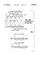
- FIG. 7is a graph comprising a series of plots of torque versus angular displacement of the rotor of the FIG. 6 eight pole, four phase disk spindle motor, illustrative of functional characteristics thereof.
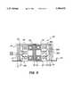
- FIG. 8is a diagrammatic view in cross section of an alternative embodiment of the present invention in which a single stator assembly formed e.g. by injection molding holds a plurality of coils and defines plural motor phases with respect to a rotating disk hub illustrated in FIG. 4A.
- a single stator assemblyformed e.g. by injection molding holds a plurality of coils and defines plural motor phases with respect to a rotating disk hub illustrated in FIG. 4A.
- FIG. 9is a simplified electrical block diagram for controlling the FIG. 1 hard disk drive head and disk assembly.
- the head and disk assembly 10includes a base 12 preferably formed as a stamping from steel alloy sheet metal. Alternatively, the base may be an aluminum alloy plate and have stamped steel side rails 13 mounted along both longitudinal edges thereof.
- the base 12aligns and supports a disk spindle 14 to which at least one data storage disk 16 is rotatably mounted.
- the spindle 14comprises and includes a three phase in-hub spindle motor 20 (FIGS. 4-5) or a two phase in-hub spindle motor 20' (FIGS. 6-7) exemplifying principles of the present invention. Details of each of the two presently preferred spindle motors are given hereafter.
- the disk drive head and disk assembly 10also includes e.g. a mass balanced rotary voice coil actuator structure 18 mounted to the base 12 which positions at least one data transducer write/read head structure 20 relative to a multiplicity of concentric data tracks defined on the storage surface of the disk 16.
- the base 12aligns and secures the spindle assembly 14 and the actuator assembly 18 so that axes of rotation thereof are parallel, and provides sufficient rigidity to these assemblies to obviate off-track conditions during reading and writing operations, when a particular data track is being followed by the head structure 20.
- a cover, not shown, which may be formed as a stamped sheet metal "dish" structuremounts to the base 12 via a gasket and suitable fasteners (also not shown).
- the combination of the base 12 and coverenclose and seal a space defined by the base 12, spindle 14, disk 16 and actuator assembly 18, so that the enclosed space may be kept free of dust and other contaminating particles as is conventional in Winchester hard disk technology.
- a breather filtermay permit internal pressure to equalize with external ambient pressure without permitting intrusion of contaminating particulates.
- An actuator latch structureis also preferably provided to latch the actuator structure at a position aligning the data transducer head structure over an inner landing zone of the disk 16.
- An aerodynamic actuator latchsuch as shown in commonly assigned U.S.
- hard disk drive electronicsinclude a preamplifier/write driver circuit 24 which is conventionally located in close proximity to the data transducer head 22 to increase signal to noise ratio.
- the circuit 24is most preferably located inside of the space enclosed by the base 12 and its cover, and a suitable connection path, usually a flex-circuit, extends from the preamplifier/write driver circuit 24 to externally mounted electronics 26.
- the electronics 26includes a read/write channel 28 which converts between digital and analog data signals for magnetic recording.
- the circuit 28also includes a data synchronizer which generates clocking signals, such as "byte clock", needed to frame coded data words upon reading a serial analog data stream from the disk 16.
- An integrated drive electronics chipincludes an encoder/decoder which encodes and decodes coded data sent to and from the disk into user data values. It also includes a buffer memory controller for controlling addressing of an external buffer memory 32 which stores user data blocks in transit between the disk and an external computing device to which the disk drive assembly 10 is connected.
- the circuitalso includes a bus level interface controller for receiving commands from the host via an interface bus 34 and for sending blocks of data between the buffer memory 32 and the host via the bus 34.
- the drive electronics chipalso includes a data sequencer, address mark decoder, and error correction circuit, and it further includes a servo data decoder which decodes servo data embedded in servo sectors recorded in the data tracks of the data storage disk 16.
- a master clock circuit, and a motor speed regulation circuitare also formed within the drive chip 30.
- the chip 30also includes an interface leading to a programmed microcontroller chip 36 via a bus 50.
- the microcontroller chip 36is multi-tasked. It controls flow of data blocks between the disk and the host in accordance with commands it receives and decodes from the interface in the drive chip 30. It also receives servo information from the servo decoder section of the drive chip 30 and generates head positioning control values which are sent via the bus 50 to an actuator control and driver circuit 40 which in turn generates driving currents and applies them to a coil to position the rotary actuator structure 18 at each selected data storage track location.
- the microcontroller 36further controls spinup of the disk spindle motor 20 and disk 16 at power-up, and monitors spindle motor speed during disk drive operations. Control of the spindle motor 20 is carried out via the bus 50 and a spindle motor control and driver circuit 38.
- the actuator voice coil control and driver circuit 40 and the spindle motor control and driver circuit 38are formed as a single analog process integrated circuit chip, such as the Texas Instruments TL2204, or equivalent.
- the data storage disk 16is centered and mounted to a rotating hub 70 of the spindle motor 20 by a disk clamp.
- the data storage diskmay have any suitable diameter, although diameters of 95mm (3.5 inch form factor) or 65 mm (2.5 inch form factor) are presently preferred.
- the diskmay be formed of an aluminum alloy substrate, or other suitable substrate such as glass or ceramic, to which a suitable thin film magnetic media is applied to the surfaces thereof e.g. by sputtering.
- Functional details of the FIG. 9 electronics as well as an exemplary preferred data formatare described in commonly assigned U.S. Pat. No. 5,255,136 to Machado et al., entitled: "High Capacity Submicro-Winchester Fixed Disk Drive", the disclosure thereof being incorporated herein by reference.
- the heads 22A and 22Bare formed upon sliders which fly upon an air bearing resulting when the disk 16 is rotated at its intended velocity.
- the disk 16is made to be very smooth so that a relatively low flying height of 2.5 to 4 microinches may be maintained between each slider and its respective data storage surface during normal disk drive operations.
- Each head 22A, 22Bmay be formed as a thin film deposition upon a ferrite slider, or as a metal-in-gap head, or as a magneto resistive read head, inductive write head composite structure, depending upon desired data densities and performance characteristics.
- low cost three phase spindle motor assemblies 20 and 20'include the rotating disk hub 70 which may be suitably formed by machining from aluminum alloy.
- the hub 70includes an opening 72 concentric with an axis of rotation 71 of the hub 70 and an outer cylindrical wall 74 sized to match an inner opening of the data storage disk 20.
- the storage diskrests upon a lower annular flange 75 projecting outwardly from the hub 70.
- a steel shaft 76is press-fit into the opening 72 of the disk hub 70 and extends downwardly therefrom.
- the steel shaft 76rotates with the hub
- a fixed steel shaftwhich is mounted to the base 12 and in which the bearing assembly is mounted between the fixed shaft and the rotating hub.
- a flux-return yoke 78 of ferromagnetic materialfits against an inside cylindrical wall of the hub 70.
- a molded permanent magnet 80is magnetized to have e.g. eight alternating North-South magnetic poles on an inner face (and opposite poles on a corresponding outer face adjacent the flux return yoke 78).
- a bearing assemblyincludes an upper bearing 82 and a lower bearing 84.
- An inner opening of the bearing assemblyfits over the shaft 76, while outer cylindrical walls of the bearings 82, 84 are fit into an annular steel sleeve 98 and glued in place with a suitable adhesive.
- the sleeve 98includes an outwardly projecting lower flange 100.
- the sleeve 98receives the elements shown in exploded view in FIG. 5 and provides flux return paths between the three pairs of stator disks.
- the sleeve 98is fixedly mounted to the base 12, so that the hub 70 and shaft 76 are free to rotate relative to the base 12 about the axis of rotation 71.
- stator disks 86, 88, 90 and 92are die-stamped from a suitable ferromagnetic material, such as a single sheet of silicon iron, or are formed as laminations of stampings from ferromagnetic material.
- the stator disks 86 and 88form an upper stator pair (phase U)
- stator disks 88 and 90form a middle stator pair (phase V)
- stator disks 90 and 92form a lower stator pair (phase W).
- Each stator diskis identical with the other and defines a plurality of radially extending pole portions. In this embodiment with an eight pole magnet 80, four pole ends 102 are formed.
- Each pole end 102has a circumferential arc length (denoted by the reference character w in FIG. 4B) selected to minimize cogging torque and to maximize excitation torque.
- Each stator disk 86, 88, 90 and 92is circumferentially displaced its adjacent disk or disks by 15 degrees of rotation (mechanical, which equates to 60 degrees of electrical rotation)
- Three preformed coils 94, 96 and 97are placed between the four stator disks 86, 88, 90 and 92 as shown in FIG. 4B.
- stator pole endsWhen current is selectively passed through progressively selected pairs of series-connected coil phases U, V and W, the stator pole ends develop electromagnetic fields which co-act with the magnetic fields of the permanent magnet 80 such that desired unidirectional rotational force is imparted to the magnet 80 and in turn to the flux return plate 78 and disk hub 70.
- This resultant torqueis graphed in FIG. 4C which shows the torque contribution of each one of the stator disks 86, 88, 90 and 92 as a function of time.
- the current through the progressively selected coil pairsis switched at switch points SP as shown at the top of FIG. 4c.
- the switch points in this exampleare spaced at 60 degrees (electrical).
- FIGS. 5A and 5BAn arrangement providing slightly improved torque output is shown in FIGS. 5A and 5B.
- six stator disks 86, 88, 90, 92, 93 and 95are die-stamped from a suitable ferromagnetic material, such as single sheet or insulated laminar sheets of silicon iron sheet metal.
- Stator disks 86 and 88form an upper stator pair (phase U)
- stator disks 90 and 92form a middle stator pair (phase V)
- stator disks 93 and 95form a lower stator pair (phase W).
- each stator diskis identical with the other, and includes e.g. four radially extending pole ends 102.
- Each pole end 102has a circumferential arc length (denoted by reference character w in FIG. 4B) configured to control cogging torque in order to smooth out the torque ripple of the spindle motor and also to maximize excitation torque.
- the pole ends 102 of each stator disk 86-95are centered at zero, 90, 180 and 270 degrees about the circumference of each stator plate.
- stator disk 86 of the upper pairis arranged to have a zero degrees (or 90 degrees) orientation with a uniform angular reference line 106 normal to an longitudinal explosion axis of the motor 20 as shown in FIG. 2.
- Stator disk 88is arranged to have a rotational offset of 45 degrees relative to the stator disk 86.
- stator disk 92is likewise offset by 45 degrees from stator disk 90, and disk 90 is offset by 60 electrical degrees from stator disk 86.
- Stator disk 92is offset by 45 degrees from disk 90.
- stator disk 93is offset by 120 electrical degrees from disk 86
- disk 95is offset by 45 degrees from disk 93.
- insulating disks 99separate each conductive stator disk and its adjacent coil.
- Each coilcomprises e.g. about 120 turns of 36 gauge insulated copper wire and is suitably connected via a connector to the motor drivers circuit 38.
- stator pole pairs 86+88phase U
- phase Vphase V
- 93+95phase W
- FIG. 8illustrates an embodiment which is very similar to the one illustrated in FIG. 5A, except that in the FIG. 8 embodiment, the motor 20' includes a unitary stator structure 87.
- the unitary stator structure 87may be formed by any suitable method, preferably injection molding of a suitable ferromagnetic material.
- One known and presently preferred methodmakes use of plastic injection molding techniques.
- a precision injection moldis formed. Ferromagnetic material, such as silicon-iron powder, is combined with a suitable flowable-state plastic resin binder. This mixture is injected into the mold and then cured to a solid state. The mold is then opened and a precision molded part, such as the unitary stator structure 87 is removed.
- stator disk portions 86A, 88A, 90A, 92A, 93A and 95Aeach have e.g. four pole ends 102 which correspond in magnetic pole alignment with the separate stator disks 86-95 and their respective pole ends 102, shown in FIG. 5A.
- the hub 70rotates in a predetermined direction at a nominal operating frequency, such as approximately 3600 RPM.
- a nominal operating frequencysuch as approximately 3600 RPM.
- Three phase commutation of the spindle motors 20 and 20'is carried out in accordance with any one of a number of sensor-less commutation techniques, such as the one mentioned above as described in commonly assigned, copending U.S. patent application Ser. No. 08/094,484.
- a two phase spindle motor 20"is shown in the exploded view of FIG. 6.
- the hub 70'differs slightly from the hub 70 of FIG. 4A, in that the hub 70" has a greater diameter and is located substantially below the storage disk 16.
- the annular wall 74is reduced to be coequal with the thickness of the disk 16. In this arrangement the spindle motor may achieve greater torque by having a greater diameter.
- each pole diskis identical with the other, and includes four pole ends.
- Each pole endincludes e.g., a straight side 102 and a notched or undercut side 104.
- the notched or undercut side 104 of each pole endis configured to add a controlled amount of cogging torque in order to smooth out the torque ripple of the motor.
- the pole endsare disposed at zero, 90, 180 and 270 degrees about the circumference of each stator plate.
- the stator disk 86 of the upper pair of the FIG. 6 embodimentis arranged to have a zero degrees (or 90 degrees) orientation with a uniform angular reference line 106 normal to an longitudinal explosion axis of the motor 20 as shown in FIG. 6.
- Stator disk 88is arranged to have a rotational offset of 45 degrees relative to the stator disk 86 of the upper pair.
- Stator disk 92is likewise offset by 45 degrees from stator plate 90, and plate 90 is offset by 67.5 degrees from stator disk 86.
- the lowest stator disk 92is offset by 112.5 degrees from the reference line 106.
- Two wire bobbins including coils 94 and 96are sandwiched respectively between the upper stator plate pair 86 and 88, and the lower stator plate pair 90 and 92.
- Each bobbinis formed of a suitable insulating plastic material, and may include two peripheral terminals 108 for providing electrical connections to the wire ends of each coil 94 or 96.
- a flex circuit 110is provided to connect to each bobbin terminal pair 108 and to a motor terminal block the printed circuit card carrying the spindle control and driver chip 38.
- the driving circuit 38follows any suitable two-phase bi-directional H-Bridge driver design, rather than the three-phase driver design used with the first embodiment.
- two bobbin statorsare formed in combination with the single rotating magnet 80 within the motor assembly 20: a first or upper motor comprising stator plates 86 and 88, and bobbin coil 94; and, a second or lower motor comprising stator plates 90 and 92 and bobbin coil 96. Electrical signals are applied to both coils 94 and 96 in proper phase and polarity during constant speed operation.
- Phase A in FIG. 7depicts the torque developed in the first, upper motor in response to the phase A input current
- phase Bdepicts the torque developed in the second, lower motor in response to the phase B input current.
- phase shifted sum cog torquedepicts the alteration of torque produced by shaping of the pole ends of the stator plates at edges 104.
- the graph labeled “sum excitation torque”represents a summation of the two excitation torques labeled “phase A” and “phase B”.
- the graph labeled “net torque (excitation+cog)”depicts the resultant sum of all torque forces developed within the motor 20' and applied to rotate the data storage disk 16, and represents qualitatively the resultant torque ripple.
Landscapes
- Engineering & Computer Science (AREA)
- Power Engineering (AREA)
- Rotational Drive Of Disk (AREA)
Abstract
Description
Claims (27)
Priority Applications (1)
| Application Number | Priority Date | Filing Date | Title |
|---|---|---|---|
| US08/206,596US5506458A (en) | 1994-03-04 | 1994-03-04 | Low cost permanent magnet disk spindle motor |
Applications Claiming Priority (1)
| Application Number | Priority Date | Filing Date | Title |
|---|---|---|---|
| US08/206,596US5506458A (en) | 1994-03-04 | 1994-03-04 | Low cost permanent magnet disk spindle motor |
Publications (1)
| Publication Number | Publication Date |
|---|---|
| US5506458Atrue US5506458A (en) | 1996-04-09 |
Family
ID=22767087
Family Applications (1)
| Application Number | Title | Priority Date | Filing Date |
|---|---|---|---|
| US08/206,596Expired - LifetimeUS5506458A (en) | 1994-03-04 | 1994-03-04 | Low cost permanent magnet disk spindle motor |
Country Status (1)
| Country | Link |
|---|---|
| US (1) | US5506458A (en) |
Cited By (38)
| Publication number | Priority date | Publication date | Assignee | Title |
|---|---|---|---|---|
| US5714812A (en)* | 1995-04-14 | 1998-02-03 | Norand Corporation | Combined energy and data storage system |
| US5739620A (en)* | 1997-01-03 | 1998-04-14 | Industrial Technology Research Institute | Optimum groove/pole ratio for brushless motor stator profile |
| US5744893A (en)* | 1996-11-25 | 1998-04-28 | Industrial Technology Research Institute | Brushless motor stator design |
| US5834865A (en)* | 1996-06-03 | 1998-11-10 | Tamagawa Seiki Kabushiki Kaisha | Hybrid stepping motor |
| US5856714A (en)* | 1996-07-05 | 1999-01-05 | Tamagawa Seiki Kaubushiki Kaisha | Hybrid type stepping motor |
| US5903074A (en)* | 1992-08-12 | 1999-05-11 | Seiko Epson Corporation | Brushless DC motor and method for driving the same |
| US6023117A (en)* | 1998-05-20 | 2000-02-08 | Delta Electronics, Incorporated | Motor device secured by engaging elements |
| US6144131A (en) | 1995-06-07 | 2000-11-07 | General Electric Company | Dynamoelectric machine rotor having interleaved laminations and method for forming |
| US6300695B1 (en) | 1999-07-29 | 2001-10-09 | Encap Motor Corporation | High speed spindle motor with hydrodynamic bearings |
| US6362554B1 (en) | 1999-07-29 | 2002-03-26 | Encap Motor Corporation | Stator assembly |
| US6437464B1 (en) | 1999-07-29 | 2002-08-20 | Encap Motor Corporation | Motor and disc assembly for computer hard drive |
| US6448675B1 (en)* | 2001-08-29 | 2002-09-10 | Sunonwealth Electric Machine Industry Co., Ltd. | Rotational balancing structure for an A.C. motor |
| US20020171316A1 (en)* | 2001-05-07 | 2002-11-21 | Wen-Shi Huang | Micro-motor with low cogging torque |
| US6490123B1 (en)* | 1997-11-07 | 2002-12-03 | Hitachi, Ltd. | Disc drive having 3.5 inch form factor housing and 2.5 inch form factor disk media |
| US6501616B1 (en) | 1999-07-29 | 2002-12-31 | Encap Motor Corporation | Hard disc drive with base incorporating a spindle motor stator |
| US6545382B1 (en)* | 2002-03-29 | 2003-04-08 | Western Digital Technologies, Inc. | Spindle motor including stator with magnetic flux guides |
| US20030102768A1 (en)* | 2001-04-11 | 2003-06-05 | Sunonwealth Electric Machine Industry Co., Ltd. | Stator assembly structure of a direct current brushless motor |
| US6617721B1 (en) | 1999-07-29 | 2003-09-09 | Encap Motor Corporation | High speed spindle motor |
| US20040034988A1 (en)* | 2001-03-02 | 2004-02-26 | Neal Griffith D. | Stator assembly made from a molded web of core segments and motor using same |
| US6753628B1 (en) | 1999-07-29 | 2004-06-22 | Encap Motor Corporation | High speed spindle motor for disc drive |
| US20040223255A1 (en)* | 2003-05-07 | 2004-11-11 | Parsoneault Norbert Steven | Fluid dynamic bearing spindle motor |
| US6844636B2 (en) | 1999-12-17 | 2005-01-18 | Encap Motor Corporation | Spindle motor with encapsulated stator and method of making same |
| US6892439B1 (en) | 2001-02-01 | 2005-05-17 | Encap Motor Corporation | Motor with stator made from linear core preform |
| US20140292129A1 (en)* | 2013-03-26 | 2014-10-02 | Sanyo Denki Co., Ltd. | Thin motor |
| US20140353971A1 (en)* | 2011-08-15 | 2014-12-04 | Oceana Energy Company | Magnetic bearings and related systems and methods |
| JP2016538817A (en)* | 2013-10-14 | 2016-12-08 | エコラッド リミテッド | Transverse flux type electric machine |
| US10060473B2 (en) | 2009-10-29 | 2018-08-28 | Oceana Energy Company | Energy conversion systems and methods |
| USD924406S1 (en)* | 2010-02-01 | 2021-07-06 | Abbott Diabetes Care Inc. | Analyte sensor inserter |
| USD955599S1 (en) | 2009-02-03 | 2022-06-21 | Abbott Diabetes Care Inc. | Analyte sensor inserter |
| USD961778S1 (en) | 2006-02-28 | 2022-08-23 | Abbott Diabetes Care Inc. | Analyte sensor device |
| USD962446S1 (en) | 2009-08-31 | 2022-08-30 | Abbott Diabetes Care, Inc. | Analyte sensor device |
| USD979766S1 (en) | 2005-09-30 | 2023-02-28 | Abbott Diabetes Care Inc. | Analyte sensor device |
| USD980986S1 (en) | 2015-05-14 | 2023-03-14 | Abbott Diabetes Care Inc. | Analyte sensor inserter |
| USD982762S1 (en) | 2020-12-21 | 2023-04-04 | Abbott Diabetes Care Inc. | Analyte sensor inserter |
| USD987830S1 (en) | 2010-03-24 | 2023-05-30 | Abbott Diabetes Care Inc. | Analyte sensor inserter |
| USD1002852S1 (en) | 2019-06-06 | 2023-10-24 | Abbott Diabetes Care Inc. | Analyte sensor device |
| US20240161776A1 (en)* | 2022-11-15 | 2024-05-16 | Western Digital Technologies, Inc. | Rotating electromagnet for removable disk clamp |
| USD1036674S1 (en) | 2011-12-11 | 2024-07-23 | Abbott Diabetes Care Inc. | Analyte sensor device |
Citations (8)
| Publication number | Priority date | Publication date | Assignee | Title |
|---|---|---|---|---|
| US3238399A (en)* | 1960-07-26 | 1966-03-01 | Philips Corp | Self-starting low power synchronous step motor |
| US3806744A (en)* | 1972-12-14 | 1974-04-23 | Ibm | High frequency stepper motor |
| USRE28075E (en)* | 1972-10-19 | 1974-07-16 | Double claw tooth stator synchronous andstepping motor with indicator | |
| US4656381A (en)* | 1984-04-25 | 1987-04-07 | Fumito Komatsu | Magnetic pole structure having aternate poles extending from a point of bases, for a rotary electric machine |
| US4858044A (en)* | 1987-05-04 | 1989-08-15 | Seagate Technology, Inc. | Disc drive spindle motor with low cogging torque |
| US4899075A (en)* | 1986-03-04 | 1990-02-06 | Shinano Kenshi Kabushiki Kaisha | Two-phase DC brushless motor |
| US4987331A (en)* | 1989-03-06 | 1991-01-22 | Alex Horng | Non-brush D.C. motor with an improved stator |
| US5093599A (en)* | 1991-02-26 | 1992-03-03 | Alex Horng | Non-brush D.C. motor with new improved stator |
- 1994
- 1994-03-04USUS08/206,596patent/US5506458A/ennot_activeExpired - Lifetime
Patent Citations (8)
| Publication number | Priority date | Publication date | Assignee | Title |
|---|---|---|---|---|
| US3238399A (en)* | 1960-07-26 | 1966-03-01 | Philips Corp | Self-starting low power synchronous step motor |
| USRE28075E (en)* | 1972-10-19 | 1974-07-16 | Double claw tooth stator synchronous andstepping motor with indicator | |
| US3806744A (en)* | 1972-12-14 | 1974-04-23 | Ibm | High frequency stepper motor |
| US4656381A (en)* | 1984-04-25 | 1987-04-07 | Fumito Komatsu | Magnetic pole structure having aternate poles extending from a point of bases, for a rotary electric machine |
| US4899075A (en)* | 1986-03-04 | 1990-02-06 | Shinano Kenshi Kabushiki Kaisha | Two-phase DC brushless motor |
| US4858044A (en)* | 1987-05-04 | 1989-08-15 | Seagate Technology, Inc. | Disc drive spindle motor with low cogging torque |
| US4987331A (en)* | 1989-03-06 | 1991-01-22 | Alex Horng | Non-brush D.C. motor with an improved stator |
| US5093599A (en)* | 1991-02-26 | 1992-03-03 | Alex Horng | Non-brush D.C. motor with new improved stator |
Cited By (53)
| Publication number | Priority date | Publication date | Assignee | Title |
|---|---|---|---|---|
| US5903074A (en)* | 1992-08-12 | 1999-05-11 | Seiko Epson Corporation | Brushless DC motor and method for driving the same |
| US5714812A (en)* | 1995-04-14 | 1998-02-03 | Norand Corporation | Combined energy and data storage system |
| US6144131A (en) | 1995-06-07 | 2000-11-07 | General Electric Company | Dynamoelectric machine rotor having interleaved laminations and method for forming |
| US5834865A (en)* | 1996-06-03 | 1998-11-10 | Tamagawa Seiki Kabushiki Kaisha | Hybrid stepping motor |
| US5856714A (en)* | 1996-07-05 | 1999-01-05 | Tamagawa Seiki Kaubushiki Kaisha | Hybrid type stepping motor |
| US5744893A (en)* | 1996-11-25 | 1998-04-28 | Industrial Technology Research Institute | Brushless motor stator design |
| US5739620A (en)* | 1997-01-03 | 1998-04-14 | Industrial Technology Research Institute | Optimum groove/pole ratio for brushless motor stator profile |
| US6490123B1 (en)* | 1997-11-07 | 2002-12-03 | Hitachi, Ltd. | Disc drive having 3.5 inch form factor housing and 2.5 inch form factor disk media |
| US6023117A (en)* | 1998-05-20 | 2000-02-08 | Delta Electronics, Incorporated | Motor device secured by engaging elements |
| US6437464B1 (en) | 1999-07-29 | 2002-08-20 | Encap Motor Corporation | Motor and disc assembly for computer hard drive |
| US20070103011A1 (en)* | 1999-07-29 | 2007-05-10 | Encap Technologies, Inc. | Motor |
| US7154200B2 (en) | 1999-07-29 | 2006-12-26 | Encap Technologies, Inc. | Motor |
| US6362554B1 (en) | 1999-07-29 | 2002-03-26 | Encap Motor Corporation | Stator assembly |
| US6501616B1 (en) | 1999-07-29 | 2002-12-31 | Encap Motor Corporation | Hard disc drive with base incorporating a spindle motor stator |
| US6300695B1 (en) | 1999-07-29 | 2001-10-09 | Encap Motor Corporation | High speed spindle motor with hydrodynamic bearings |
| US6617721B1 (en) | 1999-07-29 | 2003-09-09 | Encap Motor Corporation | High speed spindle motor |
| US6753628B1 (en) | 1999-07-29 | 2004-06-22 | Encap Motor Corporation | High speed spindle motor for disc drive |
| US6844636B2 (en) | 1999-12-17 | 2005-01-18 | Encap Motor Corporation | Spindle motor with encapsulated stator and method of making same |
| US7067944B2 (en) | 1999-12-17 | 2006-06-27 | Encap Motor Corporation | Motor with encapsulated stator and method of making same |
| US6892439B1 (en) | 2001-02-01 | 2005-05-17 | Encap Motor Corporation | Motor with stator made from linear core preform |
| US7036207B2 (en) | 2001-03-02 | 2006-05-02 | Encap Motor Corporation | Stator assembly made from a plurality of toroidal core segments and motor using same |
| US20040034988A1 (en)* | 2001-03-02 | 2004-02-26 | Neal Griffith D. | Stator assembly made from a molded web of core segments and motor using same |
| US7067952B2 (en) | 2001-03-02 | 2006-06-27 | Encap Motor Corporation | Stator assembly made from a molded web of core segments and motor using same |
| US6762532B2 (en)* | 2001-04-11 | 2004-07-13 | Sunonwealth Electric Machine Industry Co., Ltd. | Stator assembly structure of a direct current brushless motor |
| US20030102768A1 (en)* | 2001-04-11 | 2003-06-05 | Sunonwealth Electric Machine Industry Co., Ltd. | Stator assembly structure of a direct current brushless motor |
| US6781277B2 (en)* | 2001-05-07 | 2004-08-24 | Delta Electronics Inc. | Micro-motor with low cogging torque |
| US20020171316A1 (en)* | 2001-05-07 | 2002-11-21 | Wen-Shi Huang | Micro-motor with low cogging torque |
| US6448675B1 (en)* | 2001-08-29 | 2002-09-10 | Sunonwealth Electric Machine Industry Co., Ltd. | Rotational balancing structure for an A.C. motor |
| US6545382B1 (en)* | 2002-03-29 | 2003-04-08 | Western Digital Technologies, Inc. | Spindle motor including stator with magnetic flux guides |
| US20040223255A1 (en)* | 2003-05-07 | 2004-11-11 | Parsoneault Norbert Steven | Fluid dynamic bearing spindle motor |
| USD979766S1 (en) | 2005-09-30 | 2023-02-28 | Abbott Diabetes Care Inc. | Analyte sensor device |
| USD961778S1 (en) | 2006-02-28 | 2022-08-23 | Abbott Diabetes Care Inc. | Analyte sensor device |
| USD957642S1 (en) | 2009-02-03 | 2022-07-12 | Abbott Diabetes Care Inc. | Analyte sensor inserter |
| USD955599S1 (en) | 2009-02-03 | 2022-06-21 | Abbott Diabetes Care Inc. | Analyte sensor inserter |
| USD957643S1 (en) | 2009-02-03 | 2022-07-12 | Abbott Diabetes Care Inc. | Analyte sensor device |
| USD962446S1 (en) | 2009-08-31 | 2022-08-30 | Abbott Diabetes Care, Inc. | Analyte sensor device |
| US10060473B2 (en) | 2009-10-29 | 2018-08-28 | Oceana Energy Company | Energy conversion systems and methods |
| USD924406S1 (en)* | 2010-02-01 | 2021-07-06 | Abbott Diabetes Care Inc. | Analyte sensor inserter |
| USD987830S1 (en) | 2010-03-24 | 2023-05-30 | Abbott Diabetes Care Inc. | Analyte sensor inserter |
| USD997362S1 (en) | 2010-03-24 | 2023-08-29 | Abbott Diabetes Care Inc. | Analyte sensor inserter |
| US20140353971A1 (en)* | 2011-08-15 | 2014-12-04 | Oceana Energy Company | Magnetic bearings and related systems and methods |
| USD1036674S1 (en) | 2011-12-11 | 2024-07-23 | Abbott Diabetes Care Inc. | Analyte sensor device |
| USD1051397S1 (en) | 2011-12-11 | 2024-11-12 | Abbott Diabetes Care Inc. | Analyte sensor device |
| US20140292129A1 (en)* | 2013-03-26 | 2014-10-02 | Sanyo Denki Co., Ltd. | Thin motor |
| JP2016538817A (en)* | 2013-10-14 | 2016-12-08 | エコラッド リミテッド | Transverse flux type electric machine |
| USD980986S1 (en) | 2015-05-14 | 2023-03-14 | Abbott Diabetes Care Inc. | Analyte sensor inserter |
| USD1002852S1 (en) | 2019-06-06 | 2023-10-24 | Abbott Diabetes Care Inc. | Analyte sensor device |
| USD1057169S1 (en) | 2019-06-06 | 2025-01-07 | Abbott Diabetes Care Inc. | Analyte sensor device |
| USD982762S1 (en) | 2020-12-21 | 2023-04-04 | Abbott Diabetes Care Inc. | Analyte sensor inserter |
| USD999913S1 (en) | 2020-12-21 | 2023-09-26 | Abbott Diabetes Care Inc | Analyte sensor inserter |
| USD1006235S1 (en) | 2020-12-21 | 2023-11-28 | Abbott Diabetes Care Inc. | Analyte sensor inserter |
| US20240161776A1 (en)* | 2022-11-15 | 2024-05-16 | Western Digital Technologies, Inc. | Rotating electromagnet for removable disk clamp |
| US12431162B2 (en)* | 2022-11-15 | 2025-09-30 | Western Digital Technologies, Inc. | Rotating electromagnet for removable disk clamp |
Similar Documents
| Publication | Publication Date | Title |
|---|---|---|
| US5506458A (en) | Low cost permanent magnet disk spindle motor | |
| EP0637022B1 (en) | Disk recording/reproducing device | |
| US6707641B1 (en) | Spindle motor having stator rim formed of concentric laminate layers | |
| JP3135529B2 (en) | Disk storage device | |
| US5500780A (en) | Disk drive spindle motor having split windings for each phase | |
| WO2000044084A2 (en) | An electric motor | |
| US5195002A (en) | Apparatus for driving information record medium | |
| JP3317479B2 (en) | Stepping motor | |
| EP0393266B1 (en) | Improved spindle motor for a disc drive | |
| US4558244A (en) | Micro stepping motor | |
| US6921999B1 (en) | Electric motor | |
| JP2002233101A (en) | Spindle motor and information record regenerator | |
| US5875069A (en) | Claw-pole synchronous motor for driving a storage device | |
| US5502605A (en) | Spindle motor of disk apparatus including an improved spindle hub | |
| JPS61199455A (en) | Stepping motor | |
| JP2591448Y2 (en) | Stator device for brushless motor | |
| JP2601014B2 (en) | Electric motor | |
| JPH0898487A (en) | Brushless motor | |
| JPH06253518A (en) | Brushless motor | |
| JP2710163B2 (en) | Spindle motor used for disk drive | |
| JP2003092864A (en) | Spindle motor for flexible disk drive | |
| JPS62125573A (en) | spindle motor | |
| JP2616782B2 (en) | Flat motor | |
| JP2502806Y2 (en) | Hard disk device | |
| JPH099598A (en) | Electric motor and drive control device for electric motor |
Legal Events
| Date | Code | Title | Description |
|---|---|---|---|
| AS | Assignment | Owner name:QUANTUM CORPORATION, CALIFORNIA Free format text:ASSIGNMENT OF ASSIGNORS INTEREST;ASSIGNORS:PACE, LOUIS G.;TACKLIND, THOMAS A.;REEL/FRAME:007049/0796 Effective date:19940304 | |
| AS | Assignment | Owner name:CANADIAN IMPERIAL BANK OF COMMERCE, AS ADMINIST Free format text:SECURITY INTEREST;ASSIGNOR:QUANTUM CORPORATION;REEL/FRAME:007152/0815 Effective date:19941003 | |
| STCF | Information on status: patent grant | Free format text:PATENTED CASE | |
| AS | Assignment | Owner name:CANADIAN IMPERIAL BANK OF COMMERCE, NEW YORK Free format text:SECURITY INTEREST;ASSIGNOR:QUANTUM CORPORATION;REEL/FRAME:008222/0215 Effective date:19961003 | |
| AS | Assignment | Owner name:CANADIAN IMPERIAL BANK, AS ADMINISTRATIVE AGENT, N Free format text:RELEASE;ASSIGNOR:QUANTUM CORPORATION;REEL/FRAME:008744/0904 Effective date:19970818 | |
| FEPP | Fee payment procedure | Free format text:PAYOR NUMBER ASSIGNED (ORIGINAL EVENT CODE: ASPN); ENTITY STATUS OF PATENT OWNER: LARGE ENTITY | |
| FPAY | Fee payment | Year of fee payment:4 | |
| AS | Assignment | Owner name:MAXTOR CORPORATION, CALIFORNIA Free format text:ASSIGNMENT OF ASSIGNORS INTEREST;ASSIGNOR:QUANTUM CORPORATION;REEL/FRAME:012653/0726 Effective date:20010724 | |
| FPAY | Fee payment | Year of fee payment:8 | |
| FPAY | Fee payment | Year of fee payment:12 | |
| REMI | Maintenance fee reminder mailed | ||
| AS | Assignment | Owner name:WELLS FARGO BANK, NATIONAL ASSOCIATION, AS COLLATERAL AGENT AND SECOND PRIORITY REPRESENTATIVE, CALIFORNIA Free format text:SECURITY AGREEMENT;ASSIGNORS:MAXTOR CORPORATION;SEAGATE TECHNOLOGY LLC;SEAGATE TECHNOLOGY INTERNATIONAL;REEL/FRAME:022757/0017 Effective date:20090507 Owner name:JPMORGAN CHASE BANK, N.A., AS ADMINISTRATIVE AGENT AND FIRST PRIORITY REPRESENTATIVE, NEW YORK Free format text:SECURITY AGREEMENT;ASSIGNORS:MAXTOR CORPORATION;SEAGATE TECHNOLOGY LLC;SEAGATE TECHNOLOGY INTERNATIONAL;REEL/FRAME:022757/0017 Effective date:20090507 Owner name:JPMORGAN CHASE BANK, N.A., AS ADMINISTRATIVE AGENT Free format text:SECURITY AGREEMENT;ASSIGNORS:MAXTOR CORPORATION;SEAGATE TECHNOLOGY LLC;SEAGATE TECHNOLOGY INTERNATIONAL;REEL/FRAME:022757/0017 Effective date:20090507 Owner name:WELLS FARGO BANK, NATIONAL ASSOCIATION, AS COLLATE Free format text:SECURITY AGREEMENT;ASSIGNORS:MAXTOR CORPORATION;SEAGATE TECHNOLOGY LLC;SEAGATE TECHNOLOGY INTERNATIONAL;REEL/FRAME:022757/0017 Effective date:20090507 | |
| AS | Assignment | Owner name:SEAGATE TECHNOLOGY INTERNATIONAL, CALIFORNIA Free format text:RELEASE;ASSIGNOR:JPMORGAN CHASE BANK, N.A., AS ADMINISTRATIVE AGENT;REEL/FRAME:025662/0001 Effective date:20110114 Owner name:SEAGATE TECHNOLOGY HDD HOLDINGS, CALIFORNIA Free format text:RELEASE;ASSIGNOR:JPMORGAN CHASE BANK, N.A., AS ADMINISTRATIVE AGENT;REEL/FRAME:025662/0001 Effective date:20110114 Owner name:SEAGATE TECHNOLOGY LLC, CALIFORNIA Free format text:RELEASE;ASSIGNOR:JPMORGAN CHASE BANK, N.A., AS ADMINISTRATIVE AGENT;REEL/FRAME:025662/0001 Effective date:20110114 Owner name:MAXTOR CORPORATION, CALIFORNIA Free format text:RELEASE;ASSIGNOR:JPMORGAN CHASE BANK, N.A., AS ADMINISTRATIVE AGENT;REEL/FRAME:025662/0001 Effective date:20110114 | |
| AS | Assignment | Owner name:THE BANK OF NOVA SCOTIA, AS ADMINISTRATIVE AGENT, CANADA Free format text:SECURITY AGREEMENT;ASSIGNOR:SEAGATE TECHNOLOGY LLC;REEL/FRAME:026010/0350 Effective date:20110118 Owner name:THE BANK OF NOVA SCOTIA, AS ADMINISTRATIVE AGENT, Free format text:SECURITY AGREEMENT;ASSIGNOR:SEAGATE TECHNOLOGY LLC;REEL/FRAME:026010/0350 Effective date:20110118 | |
| AS | Assignment | Owner name:SEAGATE TECHNOLOGY US HOLDINGS, INC., CALIFORNIA Free format text:TERMINATION AND RELEASE OF SECURITY INTEREST IN PATENT RIGHTS;ASSIGNOR:WELLS FARGO BANK, NATIONAL ASSOCIATION, AS COLLATERAL AGENT AND SECOND PRIORITY REPRESENTATIVE;REEL/FRAME:030833/0001 Effective date:20130312 Owner name:SEAGATE TECHNOLOGY LLC, CALIFORNIA Free format text:TERMINATION AND RELEASE OF SECURITY INTEREST IN PATENT RIGHTS;ASSIGNOR:WELLS FARGO BANK, NATIONAL ASSOCIATION, AS COLLATERAL AGENT AND SECOND PRIORITY REPRESENTATIVE;REEL/FRAME:030833/0001 Effective date:20130312 Owner name:EVAULT INC. (F/K/A I365 INC.), CALIFORNIA Free format text:TERMINATION AND RELEASE OF SECURITY INTEREST IN PATENT RIGHTS;ASSIGNOR:WELLS FARGO BANK, NATIONAL ASSOCIATION, AS COLLATERAL AGENT AND SECOND PRIORITY REPRESENTATIVE;REEL/FRAME:030833/0001 Effective date:20130312 Owner name:SEAGATE TECHNOLOGY INTERNATIONAL, CAYMAN ISLANDS Free format text:TERMINATION AND RELEASE OF SECURITY INTEREST IN PATENT RIGHTS;ASSIGNOR:WELLS FARGO BANK, NATIONAL ASSOCIATION, AS COLLATERAL AGENT AND SECOND PRIORITY REPRESENTATIVE;REEL/FRAME:030833/0001 Effective date:20130312 | |
| AS | Assignment | Owner name:SEAGATE TECHNOLOGY PUBLIC LIMITED COMPANY, CALIFORNIA Free format text:RELEASE BY SECURED PARTY;ASSIGNOR:THE BANK OF NOVA SCOTIA;REEL/FRAME:072193/0001 Effective date:20250303 Owner name:SEAGATE TECHNOLOGY, CALIFORNIA Free format text:RELEASE BY SECURED PARTY;ASSIGNOR:THE BANK OF NOVA SCOTIA;REEL/FRAME:072193/0001 Effective date:20250303 Owner name:SEAGATE TECHNOLOGY HDD HOLDINGS, CALIFORNIA Free format text:RELEASE BY SECURED PARTY;ASSIGNOR:THE BANK OF NOVA SCOTIA;REEL/FRAME:072193/0001 Effective date:20250303 Owner name:I365 INC., CALIFORNIA Free format text:RELEASE BY SECURED PARTY;ASSIGNOR:THE BANK OF NOVA SCOTIA;REEL/FRAME:072193/0001 Effective date:20250303 Owner name:SEAGATE TECHNOLOGY LLC, CALIFORNIA Free format text:RELEASE BY SECURED PARTY;ASSIGNOR:THE BANK OF NOVA SCOTIA;REEL/FRAME:072193/0001 Effective date:20250303 Owner name:SEAGATE TECHNOLOGY INTERNATIONAL, CAYMAN ISLANDS Free format text:RELEASE BY SECURED PARTY;ASSIGNOR:THE BANK OF NOVA SCOTIA;REEL/FRAME:072193/0001 Effective date:20250303 Owner name:SEAGATE HDD CAYMAN, CAYMAN ISLANDS Free format text:RELEASE BY SECURED PARTY;ASSIGNOR:THE BANK OF NOVA SCOTIA;REEL/FRAME:072193/0001 Effective date:20250303 Owner name:SEAGATE TECHNOLOGY (US) HOLDINGS, INC., CALIFORNIA Free format text:RELEASE BY SECURED PARTY;ASSIGNOR:THE BANK OF NOVA SCOTIA;REEL/FRAME:072193/0001 Effective date:20250303 |