US5505887A - Extrusion process for manufacturing PTFE products - Google Patents
Extrusion process for manufacturing PTFE productsDownload PDFInfo
- Publication number
- US5505887A US5505887AUS08/209,543US20954394AUS5505887AUS 5505887 AUS5505887 AUS 5505887AUS 20954394 AUS20954394 AUS 20954394AUS 5505887 AUS5505887 AUS 5505887A
- Authority
- US
- United States
- Prior art keywords
- die
- mandrel
- rotating
- elongate
- extrusion
- Prior art date
- Legal status (The legal status is an assumption and is not a legal conclusion. Google has not performed a legal analysis and makes no representation as to the accuracy of the status listed.)
- Expired - Lifetime
Links
- 238000001125extrusionMethods0.000titleclaimsabstractdescription56
- 229920001343polytetrafluoroethylenePolymers0.000titleclaimsabstractdescription48
- 239000004810polytetrafluoroethyleneSubstances0.000titleclaimsabstractdescription48
- 238000000034methodMethods0.000titleclaimsabstractdescription43
- 238000004519manufacturing processMethods0.000titledescription8
- 238000001816coolingMethods0.000claimsdescription13
- 230000015572biosynthetic processEffects0.000claimsdescription10
- 239000002826coolantSubstances0.000claimsdescription4
- 239000007788liquidSubstances0.000claimsdescription3
- 239000000126substanceSubstances0.000claimsdescription2
- 239000000463materialSubstances0.000claims2
- 230000000979retarding effectEffects0.000claims1
- 239000000523sampleSubstances0.000description12
- 238000010438heat treatmentMethods0.000description5
- 239000000314lubricantSubstances0.000description5
- 230000000694effectsEffects0.000description4
- 230000007246mechanismEffects0.000description3
- 239000011347resinSubstances0.000description3
- 229920005989resinPolymers0.000description3
- 239000013068control sampleSubstances0.000description2
- 239000012530fluidSubstances0.000description2
- 239000002184metalSubstances0.000description2
- 125000006850spacer groupChemical group0.000description2
- 230000002411adverseEffects0.000description1
- 239000012809cooling fluidSubstances0.000description1
- 230000002939deleterious effectEffects0.000description1
- 238000001704evaporationMethods0.000description1
- 230000008020evaporationEffects0.000description1
- 235000012438extruded productNutrition0.000description1
- 239000000835fiberSubstances0.000description1
- 238000002347injectionMethods0.000description1
- 239000007924injectionSubstances0.000description1
- 239000010687lubricating oilSubstances0.000description1
- 229940127554medical productDrugs0.000description1
- -1polytetrafluoroethylenePolymers0.000description1
- 230000037390scarringEffects0.000description1
- 238000007789sealingMethods0.000description1
- 229910001220stainless steelInorganic materials0.000description1
- 239000010935stainless steelSubstances0.000description1
- 229920001169thermoplasticPolymers0.000description1
- 239000004416thermosoftening plasticSubstances0.000description1
- 230000007704transitionEffects0.000description1
- 230000002792vascularEffects0.000description1
Images
Classifications
- A—HUMAN NECESSITIES
- A61—MEDICAL OR VETERINARY SCIENCE; HYGIENE
- A61L—METHODS OR APPARATUS FOR STERILISING MATERIALS OR OBJECTS IN GENERAL; DISINFECTION, STERILISATION OR DEODORISATION OF AIR; CHEMICAL ASPECTS OF BANDAGES, DRESSINGS, ABSORBENT PADS OR SURGICAL ARTICLES; MATERIALS FOR BANDAGES, DRESSINGS, ABSORBENT PADS OR SURGICAL ARTICLES
- A61L29/00—Materials for catheters, medical tubing, cannulae, or endoscopes or for coating catheters
- A61L29/04—Macromolecular materials
- A61L29/041—Macromolecular materials obtained by reactions only involving carbon-to-carbon unsaturated bonds
- B—PERFORMING OPERATIONS; TRANSPORTING
- B29—WORKING OF PLASTICS; WORKING OF SUBSTANCES IN A PLASTIC STATE IN GENERAL
- B29C—SHAPING OR JOINING OF PLASTICS; SHAPING OF MATERIAL IN A PLASTIC STATE, NOT OTHERWISE PROVIDED FOR; AFTER-TREATMENT OF THE SHAPED PRODUCTS, e.g. REPAIRING
- B29C48/00—Extrusion moulding, i.e. expressing the moulding material through a die or nozzle which imparts the desired form; Apparatus therefor
- B29C48/022—Extrusion moulding, i.e. expressing the moulding material through a die or nozzle which imparts the desired form; Apparatus therefor characterised by the choice of material
- B—PERFORMING OPERATIONS; TRANSPORTING
- B29—WORKING OF PLASTICS; WORKING OF SUBSTANCES IN A PLASTIC STATE IN GENERAL
- B29C—SHAPING OR JOINING OF PLASTICS; SHAPING OF MATERIAL IN A PLASTIC STATE, NOT OTHERWISE PROVIDED FOR; AFTER-TREATMENT OF THE SHAPED PRODUCTS, e.g. REPAIRING
- B29C48/00—Extrusion moulding, i.e. expressing the moulding material through a die or nozzle which imparts the desired form; Apparatus therefor
- B29C48/03—Extrusion moulding, i.e. expressing the moulding material through a die or nozzle which imparts the desired form; Apparatus therefor characterised by the shape of the extruded material at extrusion
- B29C48/09—Articles with cross-sections having partially or fully enclosed cavities, e.g. pipes or channels
- B29C48/10—Articles with cross-sections having partially or fully enclosed cavities, e.g. pipes or channels flexible, e.g. blown foils
- B—PERFORMING OPERATIONS; TRANSPORTING
- B29—WORKING OF PLASTICS; WORKING OF SUBSTANCES IN A PLASTIC STATE IN GENERAL
- B29C—SHAPING OR JOINING OF PLASTICS; SHAPING OF MATERIAL IN A PLASTIC STATE, NOT OTHERWISE PROVIDED FOR; AFTER-TREATMENT OF THE SHAPED PRODUCTS, e.g. REPAIRING
- B29C48/00—Extrusion moulding, i.e. expressing the moulding material through a die or nozzle which imparts the desired form; Apparatus therefor
- B29C48/25—Component parts, details or accessories; Auxiliary operations
- B29C48/30—Extrusion nozzles or dies
- B29C48/32—Extrusion nozzles or dies with annular openings, e.g. for forming tubular articles
- B29C48/33—Extrusion nozzles or dies with annular openings, e.g. for forming tubular articles with parts rotatable relative to each other
- B—PERFORMING OPERATIONS; TRANSPORTING
- B29—WORKING OF PLASTICS; WORKING OF SUBSTANCES IN A PLASTIC STATE IN GENERAL
- B29C—SHAPING OR JOINING OF PLASTICS; SHAPING OF MATERIAL IN A PLASTIC STATE, NOT OTHERWISE PROVIDED FOR; AFTER-TREATMENT OF THE SHAPED PRODUCTS, e.g. REPAIRING
- B29C48/00—Extrusion moulding, i.e. expressing the moulding material through a die or nozzle which imparts the desired form; Apparatus therefor
- B29C48/25—Component parts, details or accessories; Auxiliary operations
- B29C48/78—Thermal treatment of the extrusion moulding material or of preformed parts or layers, e.g. by heating or cooling
- B29C48/86—Thermal treatment of the extrusion moulding material or of preformed parts or layers, e.g. by heating or cooling at the nozzle zone
- B29C48/865—Heating
- B—PERFORMING OPERATIONS; TRANSPORTING
- B29—WORKING OF PLASTICS; WORKING OF SUBSTANCES IN A PLASTIC STATE IN GENERAL
- B29C—SHAPING OR JOINING OF PLASTICS; SHAPING OF MATERIAL IN A PLASTIC STATE, NOT OTHERWISE PROVIDED FOR; AFTER-TREATMENT OF THE SHAPED PRODUCTS, e.g. REPAIRING
- B29C48/00—Extrusion moulding, i.e. expressing the moulding material through a die or nozzle which imparts the desired form; Apparatus therefor
- B29C48/25—Component parts, details or accessories; Auxiliary operations
- B29C48/78—Thermal treatment of the extrusion moulding material or of preformed parts or layers, e.g. by heating or cooling
- B29C48/86—Thermal treatment of the extrusion moulding material or of preformed parts or layers, e.g. by heating or cooling at the nozzle zone
- B29C48/87—Cooling
- B—PERFORMING OPERATIONS; TRANSPORTING
- B29—WORKING OF PLASTICS; WORKING OF SUBSTANCES IN A PLASTIC STATE IN GENERAL
- B29C—SHAPING OR JOINING OF PLASTICS; SHAPING OF MATERIAL IN A PLASTIC STATE, NOT OTHERWISE PROVIDED FOR; AFTER-TREATMENT OF THE SHAPED PRODUCTS, e.g. REPAIRING
- B29C48/00—Extrusion moulding, i.e. expressing the moulding material through a die or nozzle which imparts the desired form; Apparatus therefor
- B29C48/25—Component parts, details or accessories; Auxiliary operations
- B29C48/78—Thermal treatment of the extrusion moulding material or of preformed parts or layers, e.g. by heating or cooling
- B29C48/86—Thermal treatment of the extrusion moulding material or of preformed parts or layers, e.g. by heating or cooling at the nozzle zone
- B29C48/872—Thermal treatment of the extrusion moulding material or of preformed parts or layers, e.g. by heating or cooling at the nozzle zone characterised by differential heating or cooling
- B—PERFORMING OPERATIONS; TRANSPORTING
- B29—WORKING OF PLASTICS; WORKING OF SUBSTANCES IN A PLASTIC STATE IN GENERAL
- B29C—SHAPING OR JOINING OF PLASTICS; SHAPING OF MATERIAL IN A PLASTIC STATE, NOT OTHERWISE PROVIDED FOR; AFTER-TREATMENT OF THE SHAPED PRODUCTS, e.g. REPAIRING
- B29C48/00—Extrusion moulding, i.e. expressing the moulding material through a die or nozzle which imparts the desired form; Apparatus therefor
- B29C48/03—Extrusion moulding, i.e. expressing the moulding material through a die or nozzle which imparts the desired form; Apparatus therefor characterised by the shape of the extruded material at extrusion
- B29C48/06—Rod-shaped
- B—PERFORMING OPERATIONS; TRANSPORTING
- B29—WORKING OF PLASTICS; WORKING OF SUBSTANCES IN A PLASTIC STATE IN GENERAL
- B29K—INDEXING SCHEME ASSOCIATED WITH SUBCLASSES B29B, B29C OR B29D, RELATING TO MOULDING MATERIALS OR TO MATERIALS FOR MOULDS, REINFORCEMENTS, FILLERS OR PREFORMED PARTS, e.g. INSERTS
- B29K2027/00—Use of polyvinylhalogenides or derivatives thereof as moulding material
- B29K2027/12—Use of polyvinylhalogenides or derivatives thereof as moulding material containing fluorine
- B29K2027/18—PTFE, i.e. polytetrafluorethene, e.g. ePTFE, i.e. expanded polytetrafluorethene
- B—PERFORMING OPERATIONS; TRANSPORTING
- B29—WORKING OF PLASTICS; WORKING OF SUBSTANCES IN A PLASTIC STATE IN GENERAL
- B29L—INDEXING SCHEME ASSOCIATED WITH SUBCLASS B29C, RELATING TO PARTICULAR ARTICLES
- B29L2031/00—Other particular articles
- B29L2031/753—Medical equipment; Accessories therefor
Definitions
- the present inventionrelates generally to an extrusion process for use in manufacturing PTFE products. More particularly the present invention relates to an extrusion process for manufacturing PTFE products such as grafts, patches, tubing and the like useful in medical applications.
- PTFEpolytetrafluoroethylene
- PTFE tubingis normally manufactured by a paste extrusion process. Screw injection extrusion which is typical of most thermoplastics may not be effectively used with PTFE because PTFE resin does not exhibit sufficient fluidity even when heated.
- a green tubeis formed.
- a green tubeis a tube of PTFE that must be subjected to secondary operations before it yields a usable medical product. Such secondary operations may include stretching and expanding the tube under various conditions of time, pressure and temperature.
- the paste extrusion processtends to produce a tube which has a fibrous state where its fibrils are generally longitudinally aligned in the direction of extrusion. This fibrous state formation is particularly evident where the PTFE paste includes a lubricant to assist in extrusion. Extruded tubes having fibrils longitudinally aligned in this fashion exhibit low radial or hoop strength. Such a tube is highly susceptible to tearing or rupturing.
- U.S. Pat. No. 4,225,547employs co-rotation to manufacture pipes and wire jackets.
- the mandrel and the outer portion of the extrusion dieare counter-rotated with respect to one another. While this tends to orient the fibrils in both the longitudinal and transverse direction, as set forth in the '547 patent a suitable product is only obtained by heating the tube during extrusion. In this process the die is heated to a temperature significantly above the normal paste temperature. Heating the die while counter rotating the die components results in a product where the fibrous-state formation in the direction perpendicular to extrusion is greatly enhanced.
- the present inventionprovides for the method of forming a PTFE tube.
- the methodincludes the steps of providing an extrusion apparatus having an elongate die including a die cavity and an elongate cylindrical mandrel concentrically located within the die cavity.
- the die and the mandrelare counter-rotated while a PTFE paste is passed through the annular passage defined between the die and the mandrel.
- the temperature of the die cavityis controlled during extrusion to maintain the PTFE paste passing therethrough at substantially a non-elevated temperature.
- the present inventionprovides for the rotation of a portion of the die in a first rotation direction and the rotation of the mandrel in a second rotation direction opposite the first rotation direction. Further, the relative speeds of rotation of the die and the mandrel are varied so that one of the die or mandrel is rotating faster than the other. In addition, the control of the temperature of the die is achieved by interposing a cooling substance around the die to cool the PTFE paste being extruded therethrough.
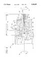
- FIG. 1shows in schematic section the die apparatus used to extrude a PTFE tube.
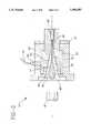
- FIG. 2shows in schematic section, a further embodiment of a die apparatus used to extrude a PTFE tube.
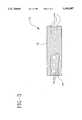
- FIG. 3is a perspective view partially broken away, of a PTFE tube formed in accordance with the present invention, showing schematically the fibrous state formation of the extruded tube.
- the extrusion apparatus 10used to forman extruded PTFE tube 12 (FIG. 3) is shown with reference to FIG. 1.
- the extrusion apparatus 10includes a conventional extruder 11 which accepts PTFE paste.
- the process of the present inventionemploys a paste extrusion process where PTFE resin is mixed with liquid lubricant.
- a lubricantis used to render the PTFE paste more fluid and easier to extrude and handle after it is formed into a tube.
- a PTFE paste of resin and lubricantis formed in a preform press (not shown) into a preform product referred to as a tubular billet 18.
- Tubular billet 18is loaded into the extruder 11 in a position where it may be fed into a die apparatus 16 in a manner which is also well known in the extrusion art.
- die apparatus 16is a multi-component device including a stationary die body 20, a rotating die element 22, a supporting plate 24 which supports die element 22 to die body 20, a mandrel 26, a die insert 28 and an insert spacer 29.
- Each of the die apparatus componentsare typically formed of metal, preferably stainless steel.
- Die body 20is generally an elongate hollow cylindrical member having a first end 30 for receiving billet 18, a second end 32 for rotationally supporting die element 22 and a central bore 34 therethrough. Die body 20 is supported by the extruder 11 in a fixed non-movable position with respect thereto.
- Die element 22is generally an elongate hollow cylindrical member having a first end 36 which is supported adjacent first end 30 of die body 20. Die element 22 also includes an opposed second end 38 which extends outwardly beyond second end 32 of die body 20. A central bore 39 is defined between the first end 36 and the second end 38 of die element 22. Bore 39 of die element 22 is in communication with bore 34 of die body 20 and together with mandrel 26 define a generally narrowing annular extrusion bore 40 for passage of tubular billet 18 in a manner which will be described in further detail hereinbelow.
- Supporting plate 24secures die element 22 to die body 20.
- Various fastening techniquesmay be used to support supporting plate 24 to die body 20 to secure die element 22 thereto.
- Die apparatus 16further includes an elongate hollow generally cylindrical die insert 28 positioned within bore 39 of die element 22 adjacent second end 38 thereof. Die insert 28 has a central bore 27 therethrough. As will be described in further detail hereinbelow, die insert 28 is used to form and regulate the outside dimension (O.D.) of tube 12 which is extruded through die apparatus 16. Die insert 28 may be interchanged with differently sized die inserts to vary the O.D. of tube 12 formed thereby.
- O.D.outside dimension
- a die spacer 29is used to support and position die insert 28 within bore 39 of die element 22.
- Extrusion bore 40is generally conical in shape having a wider end 42 for receiving billet 18 and a narrow cylindrical end 44 for the formation of tube 12.
- Mandrel 26 of die apparatus 16is an elongate generally cylindrical member centrally positioned within bore 40.
- a cylindrical end 46 of mandrel 26, adjacent first end 30 of die body 20,is wider than the opposite cylindrical end 48 adjacent die insert 28.
- a central conically tapered section 49 of mandrel 26provides a transition between wider end 46 and narrower opposite end 48.
- Cylindrical end 48 of mandrel 26is positioned centrally within bore 27 of die insert 28 and forms the inner diameter (I.D.) of tube 12.
- die element 22is supported within die body 20 for relative rotational movement with respect thereto.
- a resilient sealing member(not shown) may be interposed between the interface 21 of the two components to form a seal thereat.
- a conventional mechanismmay be secured to die element 22 to effect rotational movement thereof. Further, a conventional mechanism (also not shown) may be secured to mandrel 26 to effect its rotational movement. Die element 22 and mandrel 26 are designed to be rotated in opposite relative rotational directions. As shown in FIG. 1, die element 22 may be rotated in the rotational direction of arrow A, while mandrel 26 may be rotated in the rotational direction of arrow B, which is opposite of arrow A. As will be described in further detail hereinbelow, the conventional mechanisms used to rotate die element 22 and mandrel 26 may also vary the rotational speeds of each of die element 22 and mandrel 26.
- the present inventionfurther contemplates varying the length of the rotating outer portion of die apparatus 16, by varying the length of rotating die element 22.
- bore 40 defined between first end 30 of die body 20 and the second end 38 of die element 22 along center line lhas an overall length of d 1 .
- a lesser portion d 2 of this length, defined solely by rotating die element 22,is rotatable.
- d 2may be between about 50% and 100% of d 1 , preferably d 2 may be between about 70% and 100% of d 1 . It has been found that results such as those described hereinbelow may be varied by varying the length of the rotating portion of die apparatus 16.
- die body 20further includes cooling connection ports 50 thereon.
- Connection ports 50connect fluid tubes 52 to die body 20. This permits a chilled liquid coolant to be circulated around die body 20 so as to cool the die apparatus 16 during the extrusion process.
- the counter-rotative movement of mandrel 26 and die element 22generates frictional heat which would be imparted to the tube 12 extruded therebetween. By circulating a cooling medium throughout die apparatus 16, significant heat rise is prevented.
- Preformed tubular billet 18is loaded into the extruder 11.
- Mandrel 26is caused to rotate in the direction of arrow B and die element 22 is caused to rotate in the direction of arrow A. While providing such simultaneous counter-rotation of mandrel 26 and die element 22, tubular billet 18 is extruded through the bore 40.
- the extruded PTFE pastepasses through die insert 28 to take the tubular shape shown in FIG. 3.
- the exiting tubular extrusionmay be cut to any desired length.
- the desired non-aligned fibril structureis formed in a heated environment. Such heating could be externally induced or could be caused by the normal friction between the rotating parts.
- the present inventionprovides an extruded tube 12 having a desired non-aligned fibril structure without subjecting the die components to elevated temperatures. While the PTFE paste is being extruded through the die apparatus 16, it is prevented from heating to an elevated temperature. The friction caused by the relatively rotating parts could cause the die apparatus 16 to have a temperature rise well in excess of 125° F. By passing a cooling fluid through tube 52 and ports 50 during extrusion, the die apparatus 16 may be controlled and maintained at a substantially non-elevated temperature.
- Tube 12 formed in accordance with the present inventionshows the results of counter rotating die element 22 with respect to mandrel 26 during extrusion.
- the outer surface 13 of tube 12has fibril orientation 14 generally in a helical pattern.
- the direction of the helical fibril orientation 14corresponds to the rotation direction A of die element 22 resulting from the outer surface 13 of tube 12 being in contact with rotating second die element 22 during extrusion.
- the inner surface 15 of tube 12has a fibril orientation 19 in a helical pattern which is opposite that of fibril orientation 14 on the outer surface 13 of tube 12.
- the helical pattern on inner surface 15corresponds to rotation direction B of mandrel 26 resulting from the inner surface 15 of tube 12 being in contact with rotating mandrel 26 during extrusion.
- rotation direction Ais opposite that of rotation direction B
- the helical fibril orientation 14 and 19are also opposite one another.
- the effect of counter-rotation on the fibril orientationcan be seen.
- Significant fibril orientation in a non-longitudinally aligned directionis achieved.
- helical fibrous structuremay be achieved by varying the relative rotational rates of mandrel 26 and die element 22 (FIG. 1). Also, as above mentioned, the helical fibrous structure may also be changed by varying the length of the rotating die element 22 with respect to stationary die body 20. Generally, as the length of the rotating component is increased or as the relative rotation rates of the counter rotating parts is increased, an increase in the fibrous formation in a non-longitudinally aligned direction may be observed with an associated increase in radial tear strength.
- Table Isummarizes the resulting radial tear strength imparted to a tube formed in accordance with the FIG. 1 embodiment of the present invention, where the relative rates of rotation of mandrel 26 and die element 22 are varied.
- Die apparatus 16'is substantially similar to die apparatus 16 shown in FIG. 1 (like reference numerals referring to like components).
- mandrel 26'is modified from that shown in FIG. 1.
- One end 46' of mandrel 26is formed to have an overall conical configuration along a longitudinal extent 41'. End 46' is positioned such that extent 41' is aligned with a central portion of bore 40'.
- the conical configuration of extent 41'matches the conical configuration of bore 40' adjacent thereto.
- wider end 46'now tapers to match the taper of bore 40' thereat, a generally uniformly tapering annular cavity extent is formed therebetween. This is in distinction to the embodiment shown in FIG. 1 where the wider end 46 of mandrel 26 is generally cylindrical while the bore 40 thereadjacent is tapered or conical.
- tubular billet 18'may be more easily facilitated through an annular bore which generally is of uniform bore width over a longitudinal extent. This reduces the tendency to force billet 18' into a chamber which abruptly narrows.
- the billet 18'is more easily passed through bore 40' with less resistance being encountered as the paste passes towards extrusion die 28'.
- This resulting ease of passageallows the mandrel 26' and die element 22' to be rotated at slower rates of rotation, i.e. slower RPM's, and still provide a suitable helical formation of the fibers during extrusion.
- the slower rates of rotation of mandrel 26' and die element 22'assists in preventing excessive heat build-up of die apparatus 16' which as described above, is advantageous in providing a tube 12 which is more pliable and easier to handle.
- Table IIsummarizes the resulting radial strength imparted to a tube formed in accordance with the FIG. 2 embodiment of the present invention.
- tubes with significantly increased radial strengthcan be formed with relatively low rates of rotation of mandrel 26' and die element 22'.
- the overall efficiency and ease of operation of the process described hereinmay be achieved.
Landscapes
- Engineering & Computer Science (AREA)
- Mechanical Engineering (AREA)
- Thermal Sciences (AREA)
- Physics & Mathematics (AREA)
- Health & Medical Sciences (AREA)
- Animal Behavior & Ethology (AREA)
- Public Health (AREA)
- Chemical & Material Sciences (AREA)
- Epidemiology (AREA)
- Life Sciences & Earth Sciences (AREA)
- Manufacturing & Machinery (AREA)
- General Health & Medical Sciences (AREA)
- Chemical Kinetics & Catalysis (AREA)
- Veterinary Medicine (AREA)
- Extrusion Moulding Of Plastics Or The Like (AREA)
- Manufacture Of Porous Articles, And Recovery And Treatment Of Waste Products (AREA)
- Molding Of Porous Articles (AREA)
- Materials For Medical Uses (AREA)
- Prostheses (AREA)
- Shaping By String And By Release Of Stress In Plastics And The Like (AREA)
Abstract
Description
TABLE I ______________________________________ Die Mandrel Radial # RPM RPM Strength (kg) ______________________________________ Sample 1 No No 0.484 (Control) Rotation Rotation Sample 2 72 125 1.520 Sample 3 104 125 1.050 Sample 4 104 250 1.260 Sample 5 153 260 1.700 Sample 6No 30 0.600 Rotation ______________________________________
TABLE II ______________________________________ Die Mandrel Radial # RPM RPM Strength (kg) ______________________________________ Sample 1 10 20 0.676 Sample 2 60 80 1.277 Sample 3 60 120 0.778 Sample 4 125 250 0.889 Sample 5No 30 0.640 Rotation ______________________________________
Claims (24)
Priority Applications (12)
| Application Number | Priority Date | Filing Date | Title |
|---|---|---|---|
| US08/209,543US5505887A (en) | 1994-03-10 | 1994-03-10 | Extrusion process for manufacturing PTFE products |
| PCT/US1995/003018WO1995024304A1 (en) | 1994-03-10 | 1995-03-09 | Method for manufacturing expanded polytetrafluoroethylene products |
| EP95913639AEP0702620B1 (en) | 1994-03-10 | 1995-03-09 | Method for manufacturing expanded polytetrafluoroethylene products |
| AU19950/95AAU698139B2 (en) | 1994-03-10 | 1995-03-09 | Method for manufacturing expanded polytetrafluoroethylene products |
| DE69519071TDE69519071T2 (en) | 1994-03-10 | 1995-03-09 | METHOD FOR PRODUCING EXPANDED POLYTETRAFLUORETHYLENE |
| EP99126274AEP0992335B1 (en) | 1994-03-10 | 1995-03-09 | Apparatus for manufacturing extruded polytetrafluoroethylene products |
| DE69530876TDE69530876T2 (en) | 1994-03-10 | 1995-03-09 | Device for the production of extruded polytetrafluoroethylene products |
| US08/545,799US5874032A (en) | 1994-03-10 | 1995-03-09 | Method for manufacturing expanded polytetrafluoroethylene products |
| JP52366495AJP4065319B2 (en) | 1994-03-10 | 1995-03-09 | Method for forming PTFE tube |
| CA002161449ACA2161449C (en) | 1994-03-10 | 1995-03-09 | Method for manufacturing eptfe products |
| FI955388AFI955388A7 (en) | 1994-03-10 | 1995-11-08 | Method for manufacturing expanded polytetrafluoroethylene products |
| US09/595,548US6530765B1 (en) | 1994-03-10 | 2000-06-16 | Apparatus for manufacturing expanded polytetrafluoroethylene products |
Applications Claiming Priority (1)
| Application Number | Priority Date | Filing Date | Title |
|---|---|---|---|
| US08/209,543US5505887A (en) | 1994-03-10 | 1994-03-10 | Extrusion process for manufacturing PTFE products |
Related Child Applications (2)
| Application Number | Title | Priority Date | Filing Date |
|---|---|---|---|
| US08/545,799Continuation-In-PartUS5874032A (en) | 1994-03-10 | 1995-03-09 | Method for manufacturing expanded polytetrafluoroethylene products |
| US24521099AContinuation-In-Part | 1994-03-10 | 1999-02-05 |
Publications (1)
| Publication Number | Publication Date |
|---|---|
| US5505887Atrue US5505887A (en) | 1996-04-09 |
Family
ID=22779174
Family Applications (2)
| Application Number | Title | Priority Date | Filing Date |
|---|---|---|---|
| US08/209,543Expired - LifetimeUS5505887A (en) | 1994-03-10 | 1994-03-10 | Extrusion process for manufacturing PTFE products |
| US08/545,799Expired - LifetimeUS5874032A (en) | 1994-03-10 | 1995-03-09 | Method for manufacturing expanded polytetrafluoroethylene products |
Family Applications After (1)
| Application Number | Title | Priority Date | Filing Date |
|---|---|---|---|
| US08/545,799Expired - LifetimeUS5874032A (en) | 1994-03-10 | 1995-03-09 | Method for manufacturing expanded polytetrafluoroethylene products |
Country Status (8)
| Country | Link |
|---|---|
| US (2) | US5505887A (en) |
| EP (2) | EP0702620B1 (en) |
| JP (1) | JP4065319B2 (en) |
| AU (1) | AU698139B2 (en) |
| CA (1) | CA2161449C (en) |
| DE (2) | DE69530876T2 (en) |
| FI (1) | FI955388A7 (en) |
| WO (1) | WO1995024304A1 (en) |
Cited By (45)
| Publication number | Priority date | Publication date | Assignee | Title |
|---|---|---|---|---|
| US5874032A (en)* | 1994-03-10 | 1999-02-23 | Meadox Medicals, Inc. | Method for manufacturing expanded polytetrafluoroethylene products |
| US5965074A (en)* | 1997-02-17 | 1999-10-12 | E.I. Du Pont De Nemours And Company | Continuous paste extrusion method |
| US6158999A (en)* | 1998-08-07 | 2000-12-12 | Hartman; Steven | Rotary die |
| US6174473B1 (en)* | 1998-07-27 | 2001-01-16 | E.I. Du Pont De Nemours And Company | Paste extrusion method |
| US6309574B1 (en)* | 1994-04-04 | 2001-10-30 | Uponor Innovation Ab | Extrusion of high molecular weight polymers |
| US6432341B1 (en)* | 1999-02-26 | 2002-08-13 | Denso Corporation | Production method of ceramic moldings |
| US6506043B1 (en) | 1997-08-07 | 2003-01-14 | E. I. Du Pont De Nemours And Company | Paste extrusion apparatus |
| US6530765B1 (en) | 1994-03-10 | 2003-03-11 | Meadox Medicals, Inc. | Apparatus for manufacturing expanded polytetrafluoroethylene products |
| US20030082323A1 (en)* | 2001-10-30 | 2003-05-01 | Scimed Life Systems, Inc. | Apparatus and method for extrusion of thin-walled tubes |
| US20030082324A1 (en)* | 2001-10-30 | 2003-05-01 | Scimed Life Systems, Inc. | Green fluoropolymer tube and endovascular prosthesis formed using same |
| US20030100869A1 (en)* | 2001-07-03 | 2003-05-29 | Scimed Life Systems, Inc. | Biaxially oriented multilayer polymer tube for medical devices |
| US20030165647A1 (en)* | 2002-03-04 | 2003-09-04 | Terumo Kabushiki Kaisha | Medical tubing and extrusion die for producing the same |
| US6652257B2 (en) | 1999-02-26 | 2003-11-25 | Denso Corporation | Apparatus for producing ceramic moldings |
| US6692804B1 (en)* | 1997-02-27 | 2004-02-17 | Guill Tool & Engineering Co., Inc. | High strength extruded tubular product and method for making said product |
| US6719784B2 (en) | 2001-11-21 | 2004-04-13 | Scimed Life Systems, Inc. | Counter rotational layering of ePTFE to improve mechanical properties of a prosthesis |
| US6790213B2 (en) | 2002-01-07 | 2004-09-14 | C.R. Bard, Inc. | Implantable prosthesis |
| US20060106351A1 (en)* | 2004-11-12 | 2006-05-18 | Scimed Life Systems, Inc. | Selective surface modification of catheter tubing |
| US20060103048A1 (en)* | 2004-11-17 | 2006-05-18 | Crumm Aaron T | Extrusion die for making a part with controlled geometry |
| US20060233990A1 (en)* | 2005-04-13 | 2006-10-19 | Trivascular, Inc. | PTFE layers and methods of manufacturing |
| US20060233991A1 (en)* | 2005-04-13 | 2006-10-19 | Trivascular, Inc. | PTFE layers and methods of manufacturing |
| RU2317200C2 (en)* | 2006-02-02 | 2008-02-20 | Общество с ограниченной ответственностью Научно-производственное объединение "Этерна" | Extrusion head |
| CN100478559C (en)* | 2007-02-27 | 2009-04-15 | 南京航空航天大学 | High supersound air-intake air turbogenerator |
| US20100108355A1 (en)* | 2008-11-06 | 2010-05-06 | Axon'cable | Electric wire having a ptfe covering that is robust and that has a low dielectric constant, and a method and a tool for manufacturing the same |
| US20110180955A1 (en)* | 2005-10-17 | 2011-07-28 | Kaneka Corporation | Medical catheter tubes and process for production thereof |
| US8066755B2 (en) | 2007-09-26 | 2011-11-29 | Trivascular, Inc. | System and method of pivoted stent deployment |
| US8083789B2 (en) | 2007-11-16 | 2011-12-27 | Trivascular, Inc. | Securement assembly and method for expandable endovascular device |
| US8087923B1 (en) | 2007-05-18 | 2012-01-03 | C. R. Bard, Inc. | Extremely thin-walled ePTFE |
| RU2454592C2 (en)* | 2006-12-14 | 2012-06-27 | САИПЕМ С.п.А. | Pipe connection method, device for creating underwater pipelines and ship for laying underwater pipeline, which contains above described device |
| US8226701B2 (en) | 2007-09-26 | 2012-07-24 | Trivascular, Inc. | Stent and delivery system for deployment thereof |
| US8328861B2 (en) | 2007-11-16 | 2012-12-11 | Trivascular, Inc. | Delivery system and method for bifurcated graft |
| US8388679B2 (en) | 2007-01-19 | 2013-03-05 | Maquet Cardiovascular Llc | Single continuous piece prosthetic tubular aortic conduit and method for manufacturing the same |
| US8663309B2 (en) | 2007-09-26 | 2014-03-04 | Trivascular, Inc. | Asymmetric stent apparatus and method |
| US8696741B2 (en) | 2010-12-23 | 2014-04-15 | Maquet Cardiovascular Llc | Woven prosthesis and method for manufacturing the same |
| US20140102161A1 (en)* | 2012-10-12 | 2014-04-17 | Manchester Copper Products, Llc | Extrusion press systems and methods |
| CN103962406A (en)* | 2014-05-05 | 2014-08-06 | 天津理工大学 | Extrusion-expansion combination mold for pipe formed by flow dividing mold |
| US20140324213A1 (en)* | 2013-04-25 | 2014-10-30 | Manchester Copper Products, Llc | Extrusion press systems and methods |
| US8992595B2 (en) | 2012-04-04 | 2015-03-31 | Trivascular, Inc. | Durable stent graft with tapered struts and stable delivery methods and devices |
| US9072586B2 (en) | 2008-10-03 | 2015-07-07 | C.R. Bard, Inc. | Implantable prosthesis |
| US9364987B2 (en) | 2012-10-12 | 2016-06-14 | Manchester Copper Products, Llc | Systems and methods for cooling extruded materials |
| US9498363B2 (en) | 2012-04-06 | 2016-11-22 | Trivascular, Inc. | Delivery catheter for endovascular device |
| US10071519B2 (en)* | 2012-11-15 | 2018-09-11 | Heinz Gross | Parison head with trifunctional component and method for discharging a parison |
| US10159557B2 (en) | 2007-10-04 | 2018-12-25 | Trivascular, Inc. | Modular vascular graft for low profile percutaneous delivery |
| US10449781B2 (en) | 2013-10-09 | 2019-10-22 | Dover Europe Sarl | Apparatus and method for thermal transfer printing |
| TWI684469B (en)* | 2019-07-09 | 2020-02-11 | 國立高雄科技大學 | Die head device of developing tube |
| US11040548B1 (en) | 2019-12-10 | 2021-06-22 | Dover Europe Sarl | Thermal transfer printers for deposition of thin ink layers including a carrier belt and rigid blade |
Families Citing this family (27)
| Publication number | Priority date | Publication date | Assignee | Title |
|---|---|---|---|---|
| CA2225402C (en)* | 1995-06-26 | 2007-10-02 | Conenor Oy | Extrusion apparatus and method for orienting plastic material by using an extrusion apparatus |
| US5800512A (en)* | 1996-01-22 | 1998-09-01 | Meadox Medicals, Inc. | PTFE vascular graft |
| US6428571B1 (en) | 1996-01-22 | 2002-08-06 | Scimed Life Systems, Inc. | Self-sealing PTFE vascular graft and manufacturing methods |
| FI105391B (en) | 1996-04-04 | 2000-08-15 | Nextrom Holding Sa | Method and apparatus for manufacturing an extruded product |
| US6159320A (en) | 1998-02-06 | 2000-12-12 | Tams; F. Randy | Method and apparatus for manufacturing paint rollers |
| US6258195B1 (en) | 1999-03-19 | 2001-07-10 | Scimed Life Systems, Inc. | Multi-cord fusing manufacturing process for catheter members |
| US6454744B1 (en)* | 1999-12-23 | 2002-09-24 | Tfx Medical, Inc. | Peelable PTFE sheaths and methods for manufacture of same |
| US6939593B2 (en)* | 2001-08-27 | 2005-09-06 | Scimed Life Systems, Inc. | Medical devices utilizing melt-processible poly(tetrafluoroethylene) |
| US8419987B2 (en) | 2005-01-28 | 2013-04-16 | Mmr Marketing & Management Ag Rotkreuz | Extruder system for extruding a fluid |
| EP1910594A4 (en)* | 2005-06-25 | 2011-05-11 | Kim Reynolds | Motion transmitting cable liner and assemblies containing same |
| US20090229401A1 (en)* | 2005-06-25 | 2009-09-17 | Markel Corporation | Motion Transmitting Cable Liner and Assemblies Containing Same |
| US7905980B2 (en) | 2007-04-25 | 2011-03-15 | Seamless Technologies, Llc | Method of manufacturing paint roller covers from a tubular fabric sleeve |
| US8882957B2 (en) | 2007-04-25 | 2014-11-11 | Seamless Technologies, Llc | Methods of manufacturing paint roller covers from a tubular fabric sleeve |
| US7596972B2 (en)* | 2007-04-25 | 2009-10-06 | Seamless Technologies, Llc | Tubular knit fabric having alternating courses of sliver fiber pile and cut-pile for paint roller covers |
| FR2919750B1 (en)* | 2007-08-02 | 2016-01-08 | Axon Cable Sa | COAXIAL CABLE HAVING A LOW DIELECTRIC CONSTANT AND METHOD AND TOOL FOR MANUFACTURING THE SAME |
| US7785363B2 (en)* | 2007-08-15 | 2010-08-31 | Boston Scientific Scimed, Inc. | Skewed nodal-fibril ePTFE structure |
| US20090252926A1 (en)* | 2008-04-03 | 2009-10-08 | Boston Scientific Scimed, Inc. | Thin-walled calendered ptfe |
| US7892460B1 (en)* | 2009-02-17 | 2011-02-22 | Paradigm Optics | Enclosed drawing method |
| CN101856866B (en)* | 2010-05-28 | 2012-08-29 | 浙江理工大学 | Expanded polytetrafluoroethylene tube extrusion molding die |
| US8354619B2 (en)* | 2010-07-12 | 2013-01-15 | Axon'cable | Method of fabricating an electric wire having a PTFE-based sheath, said electric wire, and a corresponding lubricant evaporation and sintering line |
| DE102011079680A1 (en)* | 2011-07-22 | 2013-01-24 | Aesculap Ag | Coated implant and method for its manufacture |
| US20140102159A1 (en)* | 2012-10-12 | 2014-04-17 | Manchester Copper Products, Llc | Extrusion press die assembly |
| CN110248795A (en) | 2016-12-27 | 2019-09-17 | 沙特基础工业全球技术公司 | New die design for property enhancing |
| CN111231384A (en)* | 2020-01-20 | 2020-06-05 | 东南大学泰州生物医药与医疗器械研究院 | Dynamic forming method of thin-wall circular tube for degradable vascular stent |
| DE102020113695A1 (en) | 2020-05-20 | 2021-11-25 | Pneutec BV | Method and device for producing a plastic hose and a plastic hose |
| WO2025034572A2 (en)* | 2023-08-04 | 2025-02-13 | Battelle Memorial Institute | Shear-assisted extrusion configurations |
| DE102023126347A1 (en) | 2023-09-27 | 2025-03-27 | Pneutec B.V. | Method and device for producing a plastic profile |
Citations (22)
| Publication number | Priority date | Publication date | Assignee | Title |
|---|---|---|---|---|
| US2945265A (en)* | 1957-02-25 | 1960-07-19 | Revere Corp America | Method for making insulated wire |
| US3008187A (en)* | 1959-01-05 | 1961-11-14 | Raybestos Manhattan Inc | Method and apparatus for extruding polytetrafluoroethylene tubing |
| US3085290A (en)* | 1959-12-09 | 1963-04-16 | Resistoflex Corp | Method and apparatus for producing large diameter thin wall tubing of polytetrafluoroethylene |
| US3260774A (en)* | 1963-01-21 | 1966-07-12 | Tensolite Insulated Wire Co In | Method for the continuous extrusion of unsintered polytetrafluoroethylene powder |
| US3382220A (en)* | 1964-02-03 | 1968-05-07 | Phillips Petroleum Co | Transparent linear polymers |
| DE1494939A1 (en)* | 1963-06-11 | 1969-06-04 | Buddecke Dr Eckhart | Implant material and process for its manufacture |
| US3508554A (en)* | 1968-11-04 | 1970-04-28 | David S Sheridan | Medico-surgical tubes having frosted surface |
| US3907955A (en)* | 1972-08-01 | 1975-09-23 | Aeroquip Ag | Process for manufacturing electrically conductive polytetrafluoroethylene tube |
| US3950118A (en)* | 1974-05-17 | 1976-04-13 | Phillips Petroleum Company | Control of temperature profile across a heat exchanger |
| JPS5272765A (en)* | 1975-12-15 | 1977-06-17 | Sumitomo Electric Industries | Method and device for extrusion molding tetrafluoroethylene resin tubular material |
| US4104394A (en)* | 1975-12-15 | 1978-08-01 | Sumitomo Electric Industries, Ltd. | Method for diametrically expanding thermally contractive ptfe resin tube |
| US4151242A (en)* | 1975-01-15 | 1979-04-24 | Sussex Plastics Engineering Inc. | Method for extruding plastics |
| US4225547A (en)* | 1975-12-15 | 1980-09-30 | Sumitomo Electric Industries, Ltd. | Extrusion process of polytetrafluoroethylene tubing materials and apparatus therefor |
| US4250138A (en)* | 1976-09-13 | 1981-02-10 | Sumitomo Electric Industries, Ltd. | Process for producing microporous tubes of polytetrafluoroethylene |
| JPS56151535A (en)* | 1980-04-28 | 1981-11-24 | Akira Washida | Tubular body made of material principally consisting of fluorine plastic |
| US4482516A (en)* | 1982-09-10 | 1984-11-13 | W. L. Gore & Associates, Inc. | Process for producing a high strength porous polytetrafluoroethylene product having a coarse microstructure |
| JPS61143112A (en)* | 1984-12-17 | 1986-06-30 | Agency Of Ind Science & Technol | Method for solid phase extrusion of synthetic resin |
| US4647416A (en)* | 1983-08-03 | 1987-03-03 | Shiley Incorporated | Method of preparing a vascular graft prosthesis |
| US4743480A (en)* | 1986-11-13 | 1988-05-10 | W. L. Gore & Associates, Inc. | Apparatus and method for extruding and expanding polytetrafluoroethylene tubing and the products produced thereby |
| US4876051A (en)* | 1986-11-13 | 1989-10-24 | W. L. Gore & Associates, Inc. | Apparatus and method for extruding and expanding polytetrafluoroethylene tubing and the products produced thereby |
| US5156785A (en)* | 1991-07-10 | 1992-10-20 | Cordis Corporation | Extruded tubing and catheters having increased rotational stiffness |
| US5169587A (en)* | 1990-06-15 | 1992-12-08 | Symplastics Limited | Process for extruding large oriented polymer shapes |
Family Cites Families (8)
| Publication number | Priority date | Publication date | Assignee | Title |
|---|---|---|---|---|
| US2736064A (en)* | 1956-02-28 | rubin | ||
| US3404203A (en)* | 1963-05-03 | 1968-10-01 | Dow Chemical Co | Method of extruding bi-helically oriented thermoplastic tube |
| GB1170564A (en)* | 1968-03-15 | 1969-11-12 | Allied Chem | Ram Extruder for and Method of Extruding Granular Resin Materials |
| US3651187A (en)* | 1969-10-16 | 1972-03-21 | Hercules Inc | Extrusion process |
| US5098625A (en)* | 1989-03-14 | 1992-03-24 | Yeu Ming Tai Chemical Industrial Co., Ltd. | Process for forming an expanded porous tetrafluoroethylene polymer |
| US5059375A (en)* | 1989-11-13 | 1991-10-22 | Minnesota Mining & Manufacturing Company | Apparatus and method for producing kink resistant tubing |
| US5466509A (en)* | 1993-01-15 | 1995-11-14 | Impra, Inc. | Textured, porous, expanded PTFE |
| US5505887A (en)* | 1994-03-10 | 1996-04-09 | Meadox Medicals, Inc. | Extrusion process for manufacturing PTFE products |
- 1994
- 1994-03-10USUS08/209,543patent/US5505887A/ennot_activeExpired - Lifetime
- 1995
- 1995-03-09JPJP52366495Apatent/JP4065319B2/ennot_activeExpired - Fee Related
- 1995-03-09CACA002161449Apatent/CA2161449C/ennot_activeExpired - Fee Related
- 1995-03-09WOPCT/US1995/003018patent/WO1995024304A1/enactiveIP Right Grant
- 1995-03-09DEDE69530876Tpatent/DE69530876T2/ennot_activeExpired - Fee Related
- 1995-03-09AUAU19950/95Apatent/AU698139B2/ennot_activeCeased
- 1995-03-09DEDE69519071Tpatent/DE69519071T2/ennot_activeExpired - Fee Related
- 1995-03-09EPEP95913639Apatent/EP0702620B1/ennot_activeExpired - Lifetime
- 1995-03-09USUS08/545,799patent/US5874032A/ennot_activeExpired - Lifetime
- 1995-03-09EPEP99126274Apatent/EP0992335B1/ennot_activeExpired - Lifetime
- 1995-11-08FIFI955388Apatent/FI955388A7/ennot_activeApplication Discontinuation
Patent Citations (22)
| Publication number | Priority date | Publication date | Assignee | Title |
|---|---|---|---|---|
| US2945265A (en)* | 1957-02-25 | 1960-07-19 | Revere Corp America | Method for making insulated wire |
| US3008187A (en)* | 1959-01-05 | 1961-11-14 | Raybestos Manhattan Inc | Method and apparatus for extruding polytetrafluoroethylene tubing |
| US3085290A (en)* | 1959-12-09 | 1963-04-16 | Resistoflex Corp | Method and apparatus for producing large diameter thin wall tubing of polytetrafluoroethylene |
| US3260774A (en)* | 1963-01-21 | 1966-07-12 | Tensolite Insulated Wire Co In | Method for the continuous extrusion of unsintered polytetrafluoroethylene powder |
| DE1494939A1 (en)* | 1963-06-11 | 1969-06-04 | Buddecke Dr Eckhart | Implant material and process for its manufacture |
| US3382220A (en)* | 1964-02-03 | 1968-05-07 | Phillips Petroleum Co | Transparent linear polymers |
| US3508554A (en)* | 1968-11-04 | 1970-04-28 | David S Sheridan | Medico-surgical tubes having frosted surface |
| US3907955A (en)* | 1972-08-01 | 1975-09-23 | Aeroquip Ag | Process for manufacturing electrically conductive polytetrafluoroethylene tube |
| US3950118A (en)* | 1974-05-17 | 1976-04-13 | Phillips Petroleum Company | Control of temperature profile across a heat exchanger |
| US4151242A (en)* | 1975-01-15 | 1979-04-24 | Sussex Plastics Engineering Inc. | Method for extruding plastics |
| US4104394A (en)* | 1975-12-15 | 1978-08-01 | Sumitomo Electric Industries, Ltd. | Method for diametrically expanding thermally contractive ptfe resin tube |
| JPS5272765A (en)* | 1975-12-15 | 1977-06-17 | Sumitomo Electric Industries | Method and device for extrusion molding tetrafluoroethylene resin tubular material |
| US4225547A (en)* | 1975-12-15 | 1980-09-30 | Sumitomo Electric Industries, Ltd. | Extrusion process of polytetrafluoroethylene tubing materials and apparatus therefor |
| US4250138A (en)* | 1976-09-13 | 1981-02-10 | Sumitomo Electric Industries, Ltd. | Process for producing microporous tubes of polytetrafluoroethylene |
| JPS56151535A (en)* | 1980-04-28 | 1981-11-24 | Akira Washida | Tubular body made of material principally consisting of fluorine plastic |
| US4482516A (en)* | 1982-09-10 | 1984-11-13 | W. L. Gore & Associates, Inc. | Process for producing a high strength porous polytetrafluoroethylene product having a coarse microstructure |
| US4647416A (en)* | 1983-08-03 | 1987-03-03 | Shiley Incorporated | Method of preparing a vascular graft prosthesis |
| JPS61143112A (en)* | 1984-12-17 | 1986-06-30 | Agency Of Ind Science & Technol | Method for solid phase extrusion of synthetic resin |
| US4743480A (en)* | 1986-11-13 | 1988-05-10 | W. L. Gore & Associates, Inc. | Apparatus and method for extruding and expanding polytetrafluoroethylene tubing and the products produced thereby |
| US4876051A (en)* | 1986-11-13 | 1989-10-24 | W. L. Gore & Associates, Inc. | Apparatus and method for extruding and expanding polytetrafluoroethylene tubing and the products produced thereby |
| US5169587A (en)* | 1990-06-15 | 1992-12-08 | Symplastics Limited | Process for extruding large oriented polymer shapes |
| US5156785A (en)* | 1991-07-10 | 1992-10-20 | Cordis Corporation | Extruded tubing and catheters having increased rotational stiffness |
Non-Patent Citations (2)
| Title |
|---|
| Adhesion and Growth of Cultures Human Endothelial Cells on Perfluorosulphinate: Role of Vitronectin and Fibronectin in Cell Attachment, 1991, Biomaterials, vol. 12, Aug., pp. 531 539.* |
| Adhesion and Growth of Cultures Human Endothelial Cells on Perfluorosulphinate: Role of Vitronectin and Fibronectin in Cell Attachment, 1991, Biomaterials, vol. 12, Aug., pp. 531-539. |
Cited By (85)
| Publication number | Priority date | Publication date | Assignee | Title |
|---|---|---|---|---|
| US5874032A (en)* | 1994-03-10 | 1999-02-23 | Meadox Medicals, Inc. | Method for manufacturing expanded polytetrafluoroethylene products |
| US6530765B1 (en) | 1994-03-10 | 2003-03-11 | Meadox Medicals, Inc. | Apparatus for manufacturing expanded polytetrafluoroethylene products |
| US6309574B1 (en)* | 1994-04-04 | 2001-10-30 | Uponor Innovation Ab | Extrusion of high molecular weight polymers |
| US6689472B2 (en) | 1996-04-04 | 2004-02-10 | Uponor Innovation Ab | Apparatus for extrusion of polymers and plastic products formed with the apparatus |
| US5965074A (en)* | 1997-02-17 | 1999-10-12 | E.I. Du Pont De Nemours And Company | Continuous paste extrusion method |
| US6692804B1 (en)* | 1997-02-27 | 2004-02-17 | Guill Tool & Engineering Co., Inc. | High strength extruded tubular product and method for making said product |
| US6506043B1 (en) | 1997-08-07 | 2003-01-14 | E. I. Du Pont De Nemours And Company | Paste extrusion apparatus |
| US6174473B1 (en)* | 1998-07-27 | 2001-01-16 | E.I. Du Pont De Nemours And Company | Paste extrusion method |
| US6158999A (en)* | 1998-08-07 | 2000-12-12 | Hartman; Steven | Rotary die |
| US6432341B1 (en)* | 1999-02-26 | 2002-08-13 | Denso Corporation | Production method of ceramic moldings |
| US6652257B2 (en) | 1999-02-26 | 2003-11-25 | Denso Corporation | Apparatus for producing ceramic moldings |
| US7128862B2 (en)* | 2001-07-03 | 2006-10-31 | Scimed Life Systems, Inc. | Biaxially oriented multilayer polymer tube for medical devices |
| US20030100869A1 (en)* | 2001-07-03 | 2003-05-29 | Scimed Life Systems, Inc. | Biaxially oriented multilayer polymer tube for medical devices |
| US20030082324A1 (en)* | 2001-10-30 | 2003-05-01 | Scimed Life Systems, Inc. | Green fluoropolymer tube and endovascular prosthesis formed using same |
| US20030082323A1 (en)* | 2001-10-30 | 2003-05-01 | Scimed Life Systems, Inc. | Apparatus and method for extrusion of thin-walled tubes |
| US7425291B2 (en) | 2001-10-30 | 2008-09-16 | Scimed Life Systems, Inc. | Apparatus and method for extrusion of thin-walled tubes |
| US6814561B2 (en) | 2001-10-30 | 2004-11-09 | Scimed Life Systems, Inc. | Apparatus and method for extrusion of thin-walled tubes |
| US20050042402A1 (en)* | 2001-10-30 | 2005-02-24 | Scimed Life Systems, Inc. | Apparatus and method for extrusion of thin-walled tubes |
| US7597775B2 (en) | 2001-10-30 | 2009-10-06 | Boston Scientific Scimed, Inc. | Green fluoropolymer tube and endovascular prosthesis formed using same |
| US7056412B2 (en) | 2001-11-21 | 2006-06-06 | Scimed Life Systems, Inc. | Counter rotational layering of ePTFE to improve mechanical properties of a prosthesis |
| US6719784B2 (en) | 2001-11-21 | 2004-04-13 | Scimed Life Systems, Inc. | Counter rotational layering of ePTFE to improve mechanical properties of a prosthesis |
| US20040154721A1 (en)* | 2001-11-21 | 2004-08-12 | Scimed Life Systems, Inc. | Counter rotational layering of ePTFE to improve mechanical properties of a prosthesis |
| US20060195174A1 (en)* | 2001-11-21 | 2006-08-31 | Scimed Life Systems, Inc. | Counter rotational layering of ePTFE to improve mechanical properties of a prosthesis |
| US7682386B2 (en) | 2001-11-21 | 2010-03-23 | Boston Scientific Scimed, Inc. | Counter rotational layering of ePTFE to improve mechanical properties of a prosthesis |
| US7824420B2 (en) | 2002-01-07 | 2010-11-02 | C.R. Bard, Inc. | Implantable prosthesis |
| US20040215219A1 (en)* | 2002-01-07 | 2004-10-28 | C.R. Bard, Inc. | Implantable prosthesis |
| US6790213B2 (en) | 2002-01-07 | 2004-09-14 | C.R. Bard, Inc. | Implantable prosthesis |
| US20030165647A1 (en)* | 2002-03-04 | 2003-09-04 | Terumo Kabushiki Kaisha | Medical tubing and extrusion die for producing the same |
| EP1344549A1 (en)* | 2002-03-04 | 2003-09-17 | Terumo Kabushiki Kaisha | Medical tubing and extrusion die for producing the same |
| US20060106351A1 (en)* | 2004-11-12 | 2006-05-18 | Scimed Life Systems, Inc. | Selective surface modification of catheter tubing |
| US8777928B2 (en) | 2004-11-12 | 2014-07-15 | Boston Scientific Scimed, Inc. | Selective surface modification of catheter tubing |
| US9132257B2 (en) | 2004-11-12 | 2015-09-15 | Boston Scientific Scimed, Inc. | Selective surface modification of catheter tubing |
| US20110230860A1 (en)* | 2004-11-12 | 2011-09-22 | Boston Scientific Scimed, Inc. | Selective surface modification of catheter tubing |
| US7951116B2 (en) | 2004-11-12 | 2011-05-31 | Boston Scientific Scimed, Inc. | Selective surface modification of catheter tubing |
| US20060103048A1 (en)* | 2004-11-17 | 2006-05-18 | Crumm Aaron T | Extrusion die for making a part with controlled geometry |
| US9446553B2 (en) | 2005-04-13 | 2016-09-20 | Trivascular, Inc. | PTFE layers and methods of manufacturing |
| US20060233991A1 (en)* | 2005-04-13 | 2006-10-19 | Trivascular, Inc. | PTFE layers and methods of manufacturing |
| US20110040373A1 (en)* | 2005-04-13 | 2011-02-17 | Trivascular, Inc. | Ptfe layers and methods of manufacturing |
| US8840824B2 (en) | 2005-04-13 | 2014-09-23 | Trivascular, Inc. | PTFE layers and methods of manufacturing |
| US11510774B2 (en) | 2005-04-13 | 2022-11-29 | Trivascular, Inc. | PTFE layers and methods of manufacturing |
| US20090036973A1 (en)* | 2005-04-13 | 2009-02-05 | Trivascular2, Inc. | Ptfe layers and methods of manufacturing |
| US8728372B2 (en) | 2005-04-13 | 2014-05-20 | Trivascular, Inc. | PTFE layers and methods of manufacturing |
| US10864070B2 (en) | 2005-04-13 | 2020-12-15 | Trivascular, Inc. | PTFE layers and methods of manufacturing |
| US20060233990A1 (en)* | 2005-04-13 | 2006-10-19 | Trivascular, Inc. | PTFE layers and methods of manufacturing |
| US8377352B2 (en)* | 2005-10-17 | 2013-02-19 | Kaneka Corporation | Medical catheter tubes and process for production thereof |
| US20110180955A1 (en)* | 2005-10-17 | 2011-07-28 | Kaneka Corporation | Medical catheter tubes and process for production thereof |
| RU2317200C2 (en)* | 2006-02-02 | 2008-02-20 | Общество с ограниченной ответственностью Научно-производственное объединение "Этерна" | Extrusion head |
| RU2454592C2 (en)* | 2006-12-14 | 2012-06-27 | САИПЕМ С.п.А. | Pipe connection method, device for creating underwater pipelines and ship for laying underwater pipeline, which contains above described device |
| US8388679B2 (en) | 2007-01-19 | 2013-03-05 | Maquet Cardiovascular Llc | Single continuous piece prosthetic tubular aortic conduit and method for manufacturing the same |
| CN100478559C (en)* | 2007-02-27 | 2009-04-15 | 南京航空航天大学 | High supersound air-intake air turbogenerator |
| US8087923B1 (en) | 2007-05-18 | 2012-01-03 | C. R. Bard, Inc. | Extremely thin-walled ePTFE |
| US8066755B2 (en) | 2007-09-26 | 2011-11-29 | Trivascular, Inc. | System and method of pivoted stent deployment |
| US8226701B2 (en) | 2007-09-26 | 2012-07-24 | Trivascular, Inc. | Stent and delivery system for deployment thereof |
| US8663309B2 (en) | 2007-09-26 | 2014-03-04 | Trivascular, Inc. | Asymmetric stent apparatus and method |
| US12016766B2 (en) | 2007-10-04 | 2024-06-25 | Trivascular, Inc. | Modular vascular graft for low profile percutaneous delivery |
| US10682222B2 (en) | 2007-10-04 | 2020-06-16 | Trivascular, Inc. | Modular vascular graft for low profile percutaneous delivery |
| US10159557B2 (en) | 2007-10-04 | 2018-12-25 | Trivascular, Inc. | Modular vascular graft for low profile percutaneous delivery |
| US8083789B2 (en) | 2007-11-16 | 2011-12-27 | Trivascular, Inc. | Securement assembly and method for expandable endovascular device |
| US8328861B2 (en) | 2007-11-16 | 2012-12-11 | Trivascular, Inc. | Delivery system and method for bifurcated graft |
| US9072586B2 (en) | 2008-10-03 | 2015-07-07 | C.R. Bard, Inc. | Implantable prosthesis |
| US20100108355A1 (en)* | 2008-11-06 | 2010-05-06 | Axon'cable | Electric wire having a ptfe covering that is robust and that has a low dielectric constant, and a method and a tool for manufacturing the same |
| US8618417B2 (en)* | 2008-11-06 | 2013-12-31 | Axon'cable | Electric wire having a PTFE covering that is robust and that has a low dielectric constant, and a method and a tool for manufacturing the same |
| US10682221B2 (en) | 2010-12-23 | 2020-06-16 | Maquet Cardiovascular Llc | Woven prosthesis and method for manufacturing the same |
| US10010401B2 (en) | 2010-12-23 | 2018-07-03 | Maquet Cardiovascular Llc | Woven prosthesis and method for manufacturing the same |
| US9402753B2 (en) | 2010-12-23 | 2016-08-02 | Maquet Cardiovascular Llc | Woven prosthesis and method for manufacturing the same |
| US8696741B2 (en) | 2010-12-23 | 2014-04-15 | Maquet Cardiovascular Llc | Woven prosthesis and method for manufacturing the same |
| US11517417B2 (en) | 2010-12-23 | 2022-12-06 | Maquet Cardiovascular Llc | Woven prosthesis and method for manufacturing the same |
| US8992595B2 (en) | 2012-04-04 | 2015-03-31 | Trivascular, Inc. | Durable stent graft with tapered struts and stable delivery methods and devices |
| US9498363B2 (en) | 2012-04-06 | 2016-11-22 | Trivascular, Inc. | Delivery catheter for endovascular device |
| US10478879B2 (en) | 2012-10-12 | 2019-11-19 | Manchester Copper Products, Llc | Extrusion press systems and methods |
| US9346089B2 (en)* | 2012-10-12 | 2016-05-24 | Manchester Copper Products, Llc | Extrusion press systems and methods |
| US9364987B2 (en) | 2012-10-12 | 2016-06-14 | Manchester Copper Products, Llc | Systems and methods for cooling extruded materials |
| US20140102161A1 (en)* | 2012-10-12 | 2014-04-17 | Manchester Copper Products, Llc | Extrusion press systems and methods |
| JP2018034209A (en)* | 2012-10-12 | 2018-03-08 | マンチェスター カッパー プロダクツ, エルエルシー | Extrusion press system and method |
| US11305322B2 (en)* | 2012-10-12 | 2022-04-19 | Manchester Copper Products, Llc | Extrusion press systems and methods |
| US10071519B2 (en)* | 2012-11-15 | 2018-09-11 | Heinz Gross | Parison head with trifunctional component and method for discharging a parison |
| US11318513B2 (en)* | 2013-04-25 | 2022-05-03 | Manchester Copper Products, Llc | Extrusion press systems and methods |
| US10478878B2 (en) | 2013-04-25 | 2019-11-19 | Manchester Copper Products, Llc | Extrusion press systems and methods |
| US20140324213A1 (en)* | 2013-04-25 | 2014-10-30 | Manchester Copper Products, Llc | Extrusion press systems and methods |
| US9545653B2 (en)* | 2013-04-25 | 2017-01-17 | Manchester Copper Products, Llc | Extrusion press systems and methods |
| US10449781B2 (en) | 2013-10-09 | 2019-10-22 | Dover Europe Sarl | Apparatus and method for thermal transfer printing |
| CN103962406B (en)* | 2014-05-05 | 2016-06-29 | 天津理工大学 | A kind of divergent die shaping pipe squeezes swollen assembling die |
| CN103962406A (en)* | 2014-05-05 | 2014-08-06 | 天津理工大学 | Extrusion-expansion combination mold for pipe formed by flow dividing mold |
| TWI684469B (en)* | 2019-07-09 | 2020-02-11 | 國立高雄科技大學 | Die head device of developing tube |
| US11040548B1 (en) | 2019-12-10 | 2021-06-22 | Dover Europe Sarl | Thermal transfer printers for deposition of thin ink layers including a carrier belt and rigid blade |
Also Published As
| Publication number | Publication date |
|---|---|
| WO1995024304A1 (en) | 1995-09-14 |
| DE69530876T2 (en) | 2004-03-11 |
| EP0992335B1 (en) | 2003-05-21 |
| EP0992335A3 (en) | 2000-04-26 |
| EP0702620A4 (en) | 1996-12-27 |
| JPH09500843A (en) | 1997-01-28 |
| CA2161449A1 (en) | 1995-09-14 |
| DE69519071D1 (en) | 2000-11-16 |
| US5874032A (en) | 1999-02-23 |
| CA2161449C (en) | 2005-04-05 |
| AU1995095A (en) | 1995-09-25 |
| JP4065319B2 (en) | 2008-03-26 |
| EP0702620A1 (en) | 1996-03-27 |
| EP0702620B1 (en) | 2000-10-11 |
| FI955388A0 (en) | 1995-11-08 |
| EP0992335A2 (en) | 2000-04-12 |
| DE69530876D1 (en) | 2003-06-26 |
| FI955388A7 (en) | 1995-11-08 |
| DE69519071T2 (en) | 2001-06-07 |
| AU698139B2 (en) | 1998-10-22 |
Similar Documents
| Publication | Publication Date | Title |
|---|---|---|
| US5505887A (en) | Extrusion process for manufacturing PTFE products | |
| US6530765B1 (en) | Apparatus for manufacturing expanded polytetrafluoroethylene products | |
| US6689472B2 (en) | Apparatus for extrusion of polymers and plastic products formed with the apparatus | |
| US3404203A (en) | Method of extruding bi-helically oriented thermoplastic tube | |
| KR920019520A (en) | Ultra high molecular weight polyethylene thin pipe, method for manufacturing same, and apparatus for manufacturing | |
| US4225547A (en) | Extrusion process of polytetrafluoroethylene tubing materials and apparatus therefor | |
| US3279501A (en) | Extrusion and product | |
| JPH0149611B2 (en) | ||
| US5500172A (en) | Method for plasticizing particulate plastic material | |
| US2465482A (en) | Extruding apparatus | |
| JPS6052924B2 (en) | Extrusion method and two-stage single screw extrusion device | |
| WO1996006720A1 (en) | Filler reinforced thermoplastic composites having biaxially oriented components | |
| JP3843130B2 (en) | Extruding device and method for orienting plastic material by using an extruding device | |
| US3243486A (en) | Method for improving the optical properties of thermoplastic films | |
| GB2089717A (en) | An extruder for manufacturing plastic pipes | |
| DE1928843A1 (en) | Extruded plastic pipes | |
| EP0515387B1 (en) | A process for manufacture of low density polytetrofluoroethylene insulated cable | |
| US3950469A (en) | Process for the production of a plastic tube to be used as an artificial sausage casing | |
| KR100451844B1 (en) | Method and apparatus for manufacturing extruded plastic products, and this plastic products | |
| US4097564A (en) | Method of coating flexible sleeving | |
| JP3057615B2 (en) | Ultra high molecular weight polyethylene coated steel pipe | |
| KR100843609B1 (en) | Incompatible Polymer Extrusion Machine | |
| JP3051487B2 (en) | Ultra-high molecular weight polyethylene shrink pipe, method and apparatus for producing the same | |
| JPS5838310B2 (en) | cross-headed die | |
| DE2302597C3 (en) | Method and device for producing strands from crosslinkable thermoplastics or vulcanizable elastomers |
Legal Events
| Date | Code | Title | Description |
|---|---|---|---|
| AS | Assignment | Owner name:MEADOX MEDICALS, INC., NEW JERSEY Free format text:ASSIGNMENT OF ASSIGNORS INTEREST;ASSIGNORS:ZDRAHALA, R. J.;POPADIUK, NICHOLAS;KALIN, GERALD;AND OTHERS;REEL/FRAME:007278/0535 Effective date:19940608 | |
| STCF | Information on status: patent grant | Free format text:PATENTED CASE | |
| CC | Certificate of correction | ||
| FPAY | Fee payment | Year of fee payment:4 | |
| FPAY | Fee payment | Year of fee payment:8 | |
| FEPP | Fee payment procedure | Free format text:PAYOR NUMBER ASSIGNED (ORIGINAL EVENT CODE: ASPN); ENTITY STATUS OF PATENT OWNER: LARGE ENTITY Free format text:PAYER NUMBER DE-ASSIGNED (ORIGINAL EVENT CODE: RMPN); ENTITY STATUS OF PATENT OWNER: LARGE ENTITY | |
| AS | Assignment | Owner name:SCIMED LIFE SYSTEMS, INC., MINNESOTA Free format text:MERGER;ASSIGNOR:MEADOX TECHNOLOGY, INC.;REEL/FRAME:018480/0181 Effective date:19971231 Owner name:MEADOX TECHNOLOGY, INC., MINNESOTA Free format text:ASSIGNMENT OF ASSIGNORS INTEREST;ASSIGNOR:MEADOX MEDICALS, INC.;REEL/FRAME:018463/0917 Effective date:19960401 | |
| AS | Assignment | Owner name:BOSTON SCIENTIFIC SCIMED, INC., MINNESOTA Free format text:CHANGE OF NAME;ASSIGNOR:SCIMED LIFE SYSTEMS, INC.;REEL/FRAME:018463/0593 Effective date:20050101 | |
| FPAY | Fee payment | Year of fee payment:12 | |
| AS | Assignment | Owner name:ACACIA RESEARCH GROUP LLC, TEXAS Free format text:ASSIGNMENT OF ASSIGNORS INTEREST;ASSIGNOR:BOSTON SCIENTIFIC SCIMED, INC.;REEL/FRAME:030694/0461 Effective date:20121220 | |
| AS | Assignment | Owner name:LIFESHIELD SCIENCES LLC, TEXAS Free format text:ASSIGNMENT OF ASSIGNORS INTEREST;ASSIGNOR:ACACIA RESEARCH GROUP LLC;REEL/FRAME:030740/0225 Effective date:20130515 |