US5505732A - Apparatus and method of inserting spinal implants - Google Patents
Apparatus and method of inserting spinal implantsDownload PDFInfo
- Publication number
- US5505732A US5505732AUS08/481,750US48175095AUS5505732AUS 5505732 AUS5505732 AUS 5505732AUS 48175095 AUS48175095 AUS 48175095AUS 5505732 AUS5505732 AUS 5505732A
- Authority
- US
- United States
- Prior art keywords
- distractor
- implant
- outer sleeve
- bone
- vertebrae
- Prior art date
- Legal status (The legal status is an assumption and is not a legal conclusion. Google has not performed a legal analysis and makes no representation as to the accuracy of the status listed.)
- Expired - Lifetime
Links
- 238000000034methodMethods0.000titleclaimsabstractdescription125
- 239000007943implantSubstances0.000titleabstractdescription174
- 230000035515penetrationEffects0.000claimsdescription11
- 230000003116impacting effectEffects0.000claims1
- 210000000988bone and boneAnatomy0.000abstractdescription96
- 238000002360preparation methodMethods0.000abstractdescription5
- 230000004927fusionEffects0.000description47
- 238000005553drillingMethods0.000description26
- 238000005520cutting processMethods0.000description24
- 239000000463materialSubstances0.000description24
- 238000003780insertionMethods0.000description23
- 230000037431insertionEffects0.000description23
- 230000033001locomotionEffects0.000description22
- 210000005036nerveAnatomy0.000description22
- 230000009977dual effectEffects0.000description20
- 210000004705lumbosacral regionAnatomy0.000description17
- 238000001356surgical procedureMethods0.000description15
- 238000013461designMethods0.000description9
- 230000001965increasing effectEffects0.000description9
- 230000007246mechanismEffects0.000description9
- 230000000149penetrating effectEffects0.000description9
- 230000006641stabilisationEffects0.000description9
- 238000011105stabilizationMethods0.000description9
- 210000001519tissueAnatomy0.000description9
- 208000027418Wounds and injuryDiseases0.000description8
- 230000001976improved effectEffects0.000description8
- 230000001537neural effectEffects0.000description8
- 230000002146bilateral effectEffects0.000description7
- 210000004872soft tissueAnatomy0.000description7
- 206010052428WoundDiseases0.000description6
- 238000013459approachMethods0.000description6
- 230000036961partial effectEffects0.000description6
- 210000000278spinal cordAnatomy0.000description6
- 238000002513implantationMethods0.000description5
- 238000011068loading methodMethods0.000description5
- 229910052751metalInorganic materials0.000description5
- 239000002184metalSubstances0.000description5
- 239000000126substanceSubstances0.000description5
- 210000000115thoracic cavityAnatomy0.000description5
- 230000008901benefitEffects0.000description4
- 230000006378damageEffects0.000description4
- 201000010099diseaseDiseases0.000description4
- 208000037265diseases, disorders, signs and symptomsDiseases0.000description4
- 238000005516engineering processMethods0.000description4
- 210000003041ligamentAnatomy0.000description4
- 230000003466anti-cipated effectEffects0.000description3
- 210000004204blood vesselAnatomy0.000description3
- 230000006835compressionEffects0.000description3
- 238000007906compressionMethods0.000description3
- 230000007812deficiencyEffects0.000description3
- 230000000694effectsEffects0.000description3
- 238000000605extractionMethods0.000description3
- 230000006870functionEffects0.000description3
- 238000003306harvestingMethods0.000description3
- 208000014674injuryDiseases0.000description3
- 238000009434installationMethods0.000description3
- 230000014759maintenance of locationEffects0.000description3
- 230000013011matingEffects0.000description3
- 230000002188osteogenic effectEffects0.000description3
- 230000001737promoting effectEffects0.000description3
- 230000001681protective effectEffects0.000description3
- 238000012552reviewMethods0.000description3
- 238000010079rubber tappingMethods0.000description3
- 239000007787solidSubstances0.000description3
- 230000000087stabilizing effectEffects0.000description3
- 206010033799ParalysisDiseases0.000description2
- 206010033892ParaplegiaDiseases0.000description2
- 208000002847Surgical WoundDiseases0.000description2
- 206010042618Surgical procedure repeatedDiseases0.000description2
- 210000004027cellAnatomy0.000description2
- 230000003628erosive effectEffects0.000description2
- 230000012010growthEffects0.000description2
- 230000006872improvementEffects0.000description2
- 230000001939inductive effectEffects0.000description2
- 230000000977initiatory effectEffects0.000description2
- 230000007774longtermEffects0.000description2
- 238000013508migrationMethods0.000description2
- 230000005012migrationEffects0.000description2
- 238000012986modificationMethods0.000description2
- 230000004048modificationEffects0.000description2
- 210000002445nippleAnatomy0.000description2
- 230000008569processEffects0.000description2
- 230000000750progressive effectEffects0.000description2
- 230000002829reductive effectEffects0.000description2
- 238000002271resectionMethods0.000description2
- 230000035807sensationEffects0.000description2
- 210000001032spinal nerveAnatomy0.000description2
- 238000004381surface treatmentMethods0.000description2
- 230000002792vascularEffects0.000description2
- 230000000007visual effectEffects0.000description2
- 238000012800visualizationMethods0.000description2
- 210000002517zygapophyseal jointAnatomy0.000description2
- 208000036829Device dislocationDiseases0.000description1
- 241001149900Fusconaia subrotundaSpecies0.000description1
- VVQNEPGJFQJSBK-UHFFFAOYSA-NMethyl methacrylateChemical compoundCOC(=O)C(C)=CVVQNEPGJFQJSBK-UHFFFAOYSA-N0.000description1
- 206010028980NeoplasmDiseases0.000description1
- 208000008558OsteophyteDiseases0.000description1
- 241000283984RodentiaSpecies0.000description1
- RTAQQCXQSZGOHL-UHFFFAOYSA-NTitaniumChemical compound[Ti]RTAQQCXQSZGOHL-UHFFFAOYSA-N0.000description1
- 239000003522acrylic cementSubstances0.000description1
- 230000004075alterationEffects0.000description1
- 210000000709aortaAnatomy0.000description1
- 208000037873arthrodesisDiseases0.000description1
- 239000012237artificial materialSubstances0.000description1
- 230000037396body weightEffects0.000description1
- 210000002449bone cellAnatomy0.000description1
- 230000008468bone growthEffects0.000description1
- 239000004568cementSubstances0.000description1
- 238000012790confirmationMethods0.000description1
- 238000007796conventional methodMethods0.000description1
- 239000007799corkSubstances0.000description1
- 230000001054cortical effectEffects0.000description1
- 230000007423decreaseEffects0.000description1
- 230000003111delayed effectEffects0.000description1
- 230000003467diminishing effectEffects0.000description1
- 238000010494dissociation reactionMethods0.000description1
- 230000005593dissociationsEffects0.000description1
- 230000005489elastic deformationEffects0.000description1
- 230000002708enhancing effectEffects0.000description1
- 238000011049fillingMethods0.000description1
- 230000005484gravityEffects0.000description1
- 239000003102growth factorSubstances0.000description1
- 230000035876healingEffects0.000description1
- 210000001621ilium boneAnatomy0.000description1
- 208000015181infectious diseaseDiseases0.000description1
- 238000005304joiningMethods0.000description1
- 210000001503jointAnatomy0.000description1
- 230000000670limiting effectEffects0.000description1
- 238000002595magnetic resonance imagingMethods0.000description1
- 238000004519manufacturing processMethods0.000description1
- 238000012544monitoring processMethods0.000description1
- 210000003205muscleAnatomy0.000description1
- 230000000926neurological effectEffects0.000description1
- 210000000056organAnatomy0.000description1
- 230000000399orthopedic effectEffects0.000description1
- 230000011164ossificationEffects0.000description1
- 230000000737periodic effectEffects0.000description1
- 230000009467reductionEffects0.000description1
- 230000000717retained effectEffects0.000description1
- 239000011435rockSubstances0.000description1
- 210000003131sacroiliac jointAnatomy0.000description1
- 231100000241scarToxicity0.000description1
- 206010041569spinal fractureDiseases0.000description1
- 210000000273spinal nerve rootAnatomy0.000description1
- 230000000153supplemental effectEffects0.000description1
- 239000010936titaniumSubstances0.000description1
- 229910052719titaniumInorganic materials0.000description1
- 230000036346tooth eruptionEffects0.000description1
- 238000013519translationMethods0.000description1
- 238000012795verificationMethods0.000description1
Images


Classifications
- A—HUMAN NECESSITIES
- A61—MEDICAL OR VETERINARY SCIENCE; HYGIENE
- A61B—DIAGNOSIS; SURGERY; IDENTIFICATION
- A61B17/00—Surgical instruments, devices or methods
- A61B17/16—Instruments for performing osteoclasis; Drills or chisels for bones; Trepans
- A61B17/1662—Instruments for performing osteoclasis; Drills or chisels for bones; Trepans for particular parts of the body
- A61B17/1671—Instruments for performing osteoclasis; Drills or chisels for bones; Trepans for particular parts of the body for the spine
- A—HUMAN NECESSITIES
- A61—MEDICAL OR VETERINARY SCIENCE; HYGIENE
- A61B—DIAGNOSIS; SURGERY; IDENTIFICATION
- A61B17/00—Surgical instruments, devices or methods
- A61B17/16—Instruments for performing osteoclasis; Drills or chisels for bones; Trepans
- A61B17/17—Guides or aligning means for drills, mills, pins or wires
- A61B17/1739—Guides or aligning means for drills, mills, pins or wires specially adapted for particular parts of the body
- A61B17/1757—Guides or aligning means for drills, mills, pins or wires specially adapted for particular parts of the body for the spine
- A—HUMAN NECESSITIES
- A61—MEDICAL OR VETERINARY SCIENCE; HYGIENE
- A61F—FILTERS IMPLANTABLE INTO BLOOD VESSELS; PROSTHESES; DEVICES PROVIDING PATENCY TO, OR PREVENTING COLLAPSING OF, TUBULAR STRUCTURES OF THE BODY, e.g. STENTS; ORTHOPAEDIC, NURSING OR CONTRACEPTIVE DEVICES; FOMENTATION; TREATMENT OR PROTECTION OF EYES OR EARS; BANDAGES, DRESSINGS OR ABSORBENT PADS; FIRST-AID KITS
- A61F2/00—Filters implantable into blood vessels; Prostheses, i.e. artificial substitutes or replacements for parts of the body; Appliances for connecting them with the body; Devices providing patency to, or preventing collapsing of, tubular structures of the body, e.g. stents
- A61F2/02—Prostheses implantable into the body
- A61F2/30—Joints
- A61F2/44—Joints for the spine, e.g. vertebrae, spinal discs
- A61F2/4455—Joints for the spine, e.g. vertebrae, spinal discs for the fusion of spinal bodies, e.g. intervertebral fusion of adjacent spinal bodies, e.g. fusion cages
- A61F2/446—Joints for the spine, e.g. vertebrae, spinal discs for the fusion of spinal bodies, e.g. intervertebral fusion of adjacent spinal bodies, e.g. fusion cages having a circular or elliptical cross-section substantially parallel to the axis of the spine, e.g. cylinders or frustocones
- A—HUMAN NECESSITIES
- A61—MEDICAL OR VETERINARY SCIENCE; HYGIENE
- A61F—FILTERS IMPLANTABLE INTO BLOOD VESSELS; PROSTHESES; DEVICES PROVIDING PATENCY TO, OR PREVENTING COLLAPSING OF, TUBULAR STRUCTURES OF THE BODY, e.g. STENTS; ORTHOPAEDIC, NURSING OR CONTRACEPTIVE DEVICES; FOMENTATION; TREATMENT OR PROTECTION OF EYES OR EARS; BANDAGES, DRESSINGS OR ABSORBENT PADS; FIRST-AID KITS
- A61F2/00—Filters implantable into blood vessels; Prostheses, i.e. artificial substitutes or replacements for parts of the body; Appliances for connecting them with the body; Devices providing patency to, or preventing collapsing of, tubular structures of the body, e.g. stents
- A61F2/02—Prostheses implantable into the body
- A61F2/30—Joints
- A61F2/46—Special tools for implanting artificial joints
- A61F2/4603—Special tools for implanting artificial joints for insertion or extraction of endoprosthetic joints or of accessories thereof
- A61F2/4611—Special tools for implanting artificial joints for insertion or extraction of endoprosthetic joints or of accessories thereof of spinal prostheses
- A—HUMAN NECESSITIES
- A61—MEDICAL OR VETERINARY SCIENCE; HYGIENE
- A61B—DIAGNOSIS; SURGERY; IDENTIFICATION
- A61B17/00—Surgical instruments, devices or methods
- A61B17/02—Surgical instruments, devices or methods for holding wounds open, e.g. retractors; Tractors
- A61B17/025—Joint distractors
- A—HUMAN NECESSITIES
- A61—MEDICAL OR VETERINARY SCIENCE; HYGIENE
- A61B—DIAGNOSIS; SURGERY; IDENTIFICATION
- A61B17/00—Surgical instruments, devices or methods
- A61B17/16—Instruments for performing osteoclasis; Drills or chisels for bones; Trepans
- A—HUMAN NECESSITIES
- A61—MEDICAL OR VETERINARY SCIENCE; HYGIENE
- A61B—DIAGNOSIS; SURGERY; IDENTIFICATION
- A61B17/00—Surgical instruments, devices or methods
- A61B17/16—Instruments for performing osteoclasis; Drills or chisels for bones; Trepans
- A61B17/17—Guides or aligning means for drills, mills, pins or wires
- A—HUMAN NECESSITIES
- A61—MEDICAL OR VETERINARY SCIENCE; HYGIENE
- A61B—DIAGNOSIS; SURGERY; IDENTIFICATION
- A61B17/00—Surgical instruments, devices or methods
- A61B17/32—Surgical cutting instruments
- A—HUMAN NECESSITIES
- A61—MEDICAL OR VETERINARY SCIENCE; HYGIENE
- A61B—DIAGNOSIS; SURGERY; IDENTIFICATION
- A61B17/00—Surgical instruments, devices or methods
- A61B17/56—Surgical instruments or methods for treatment of bones or joints; Devices specially adapted therefor
- A61B17/58—Surgical instruments or methods for treatment of bones or joints; Devices specially adapted therefor for osteosynthesis, e.g. bone plates, screws or setting implements
- A61B17/88—Osteosynthesis instruments; Methods or means for implanting or extracting internal or external fixation devices
- A61B17/8875—Screwdrivers, spanners or wrenches
- A61B17/8886—Screwdrivers, spanners or wrenches holding the screw head
- A61B17/8888—Screwdrivers, spanners or wrenches holding the screw head at its central region
- A—HUMAN NECESSITIES
- A61—MEDICAL OR VETERINARY SCIENCE; HYGIENE
- A61B—DIAGNOSIS; SURGERY; IDENTIFICATION
- A61B17/00—Surgical instruments, devices or methods
- A61B17/02—Surgical instruments, devices or methods for holding wounds open, e.g. retractors; Tractors
- A61B17/025—Joint distractors
- A61B2017/0256—Joint distractors for the spine
- A—HUMAN NECESSITIES
- A61—MEDICAL OR VETERINARY SCIENCE; HYGIENE
- A61B—DIAGNOSIS; SURGERY; IDENTIFICATION
- A61B17/00—Surgical instruments, devices or methods
- A61B17/56—Surgical instruments or methods for treatment of bones or joints; Devices specially adapted therefor
- A61B17/58—Surgical instruments or methods for treatment of bones or joints; Devices specially adapted therefor for osteosynthesis, e.g. bone plates, screws or setting implements
- A61B17/88—Osteosynthesis instruments; Methods or means for implanting or extracting internal or external fixation devices
- A61B17/92—Impactors or extractors, e.g. for removing intramedullary devices
- A61B2017/922—Devices for impaction, impact element
- A—HUMAN NECESSITIES
- A61—MEDICAL OR VETERINARY SCIENCE; HYGIENE
- A61B—DIAGNOSIS; SURGERY; IDENTIFICATION
- A61B90/00—Instruments, implements or accessories specially adapted for surgery or diagnosis and not covered by any of the groups A61B1/00 - A61B50/00, e.g. for luxation treatment or for protecting wound edges
- A61B90/03—Automatic limiting or abutting means, e.g. for safety
- A61B2090/033—Abutting means, stops, e.g. abutting on tissue or skin
- A61B2090/036—Abutting means, stops, e.g. abutting on tissue or skin abutting on tissue or skin
- A—HUMAN NECESSITIES
- A61—MEDICAL OR VETERINARY SCIENCE; HYGIENE
- A61F—FILTERS IMPLANTABLE INTO BLOOD VESSELS; PROSTHESES; DEVICES PROVIDING PATENCY TO, OR PREVENTING COLLAPSING OF, TUBULAR STRUCTURES OF THE BODY, e.g. STENTS; ORTHOPAEDIC, NURSING OR CONTRACEPTIVE DEVICES; FOMENTATION; TREATMENT OR PROTECTION OF EYES OR EARS; BANDAGES, DRESSINGS OR ABSORBENT PADS; FIRST-AID KITS
- A61F2/00—Filters implantable into blood vessels; Prostheses, i.e. artificial substitutes or replacements for parts of the body; Appliances for connecting them with the body; Devices providing patency to, or preventing collapsing of, tubular structures of the body, e.g. stents
- A61F2/02—Prostheses implantable into the body
- A61F2/30—Joints
- A61F2/30721—Accessories
- A61F2/30744—End caps, e.g. for closing an endoprosthetic cavity
- A—HUMAN NECESSITIES
- A61—MEDICAL OR VETERINARY SCIENCE; HYGIENE
- A61F—FILTERS IMPLANTABLE INTO BLOOD VESSELS; PROSTHESES; DEVICES PROVIDING PATENCY TO, OR PREVENTING COLLAPSING OF, TUBULAR STRUCTURES OF THE BODY, e.g. STENTS; ORTHOPAEDIC, NURSING OR CONTRACEPTIVE DEVICES; FOMENTATION; TREATMENT OR PROTECTION OF EYES OR EARS; BANDAGES, DRESSINGS OR ABSORBENT PADS; FIRST-AID KITS
- A61F2/00—Filters implantable into blood vessels; Prostheses, i.e. artificial substitutes or replacements for parts of the body; Appliances for connecting them with the body; Devices providing patency to, or preventing collapsing of, tubular structures of the body, e.g. stents
- A61F2/02—Prostheses implantable into the body
- A61F2/30—Joints
- A61F2/44—Joints for the spine, e.g. vertebrae, spinal discs
- A61F2/442—Intervertebral or spinal discs, e.g. resilient
- A—HUMAN NECESSITIES
- A61—MEDICAL OR VETERINARY SCIENCE; HYGIENE
- A61F—FILTERS IMPLANTABLE INTO BLOOD VESSELS; PROSTHESES; DEVICES PROVIDING PATENCY TO, OR PREVENTING COLLAPSING OF, TUBULAR STRUCTURES OF THE BODY, e.g. STENTS; ORTHOPAEDIC, NURSING OR CONTRACEPTIVE DEVICES; FOMENTATION; TREATMENT OR PROTECTION OF EYES OR EARS; BANDAGES, DRESSINGS OR ABSORBENT PADS; FIRST-AID KITS
- A61F2/00—Filters implantable into blood vessels; Prostheses, i.e. artificial substitutes or replacements for parts of the body; Appliances for connecting them with the body; Devices providing patency to, or preventing collapsing of, tubular structures of the body, e.g. stents
- A61F2/02—Prostheses implantable into the body
- A61F2/30—Joints
- A61F2/44—Joints for the spine, e.g. vertebrae, spinal discs
- A61F2/4455—Joints for the spine, e.g. vertebrae, spinal discs for the fusion of spinal bodies, e.g. intervertebral fusion of adjacent spinal bodies, e.g. fusion cages
- A—HUMAN NECESSITIES
- A61—MEDICAL OR VETERINARY SCIENCE; HYGIENE
- A61F—FILTERS IMPLANTABLE INTO BLOOD VESSELS; PROSTHESES; DEVICES PROVIDING PATENCY TO, OR PREVENTING COLLAPSING OF, TUBULAR STRUCTURES OF THE BODY, e.g. STENTS; ORTHOPAEDIC, NURSING OR CONTRACEPTIVE DEVICES; FOMENTATION; TREATMENT OR PROTECTION OF EYES OR EARS; BANDAGES, DRESSINGS OR ABSORBENT PADS; FIRST-AID KITS
- A61F2/00—Filters implantable into blood vessels; Prostheses, i.e. artificial substitutes or replacements for parts of the body; Appliances for connecting them with the body; Devices providing patency to, or preventing collapsing of, tubular structures of the body, e.g. stents
- A61F2/02—Prostheses implantable into the body
- A61F2/30—Joints
- A61F2/46—Special tools for implanting artificial joints
- A61F2/4603—Special tools for implanting artificial joints for insertion or extraction of endoprosthetic joints or of accessories thereof
- A—HUMAN NECESSITIES
- A61—MEDICAL OR VETERINARY SCIENCE; HYGIENE
- A61F—FILTERS IMPLANTABLE INTO BLOOD VESSELS; PROSTHESES; DEVICES PROVIDING PATENCY TO, OR PREVENTING COLLAPSING OF, TUBULAR STRUCTURES OF THE BODY, e.g. STENTS; ORTHOPAEDIC, NURSING OR CONTRACEPTIVE DEVICES; FOMENTATION; TREATMENT OR PROTECTION OF EYES OR EARS; BANDAGES, DRESSINGS OR ABSORBENT PADS; FIRST-AID KITS
- A61F2/00—Filters implantable into blood vessels; Prostheses, i.e. artificial substitutes or replacements for parts of the body; Appliances for connecting them with the body; Devices providing patency to, or preventing collapsing of, tubular structures of the body, e.g. stents
- A61F2/02—Prostheses implantable into the body
- A61F2/30—Joints
- A61F2/46—Special tools for implanting artificial joints
- A61F2/4657—Measuring instruments used for implanting artificial joints
- A—HUMAN NECESSITIES
- A61—MEDICAL OR VETERINARY SCIENCE; HYGIENE
- A61F—FILTERS IMPLANTABLE INTO BLOOD VESSELS; PROSTHESES; DEVICES PROVIDING PATENCY TO, OR PREVENTING COLLAPSING OF, TUBULAR STRUCTURES OF THE BODY, e.g. STENTS; ORTHOPAEDIC, NURSING OR CONTRACEPTIVE DEVICES; FOMENTATION; TREATMENT OR PROTECTION OF EYES OR EARS; BANDAGES, DRESSINGS OR ABSORBENT PADS; FIRST-AID KITS
- A61F2/00—Filters implantable into blood vessels; Prostheses, i.e. artificial substitutes or replacements for parts of the body; Appliances for connecting them with the body; Devices providing patency to, or preventing collapsing of, tubular structures of the body, e.g. stents
- A61F2/02—Prostheses implantable into the body
- A61F2/28—Bones
- A61F2002/2835—Bone graft implants for filling a bony defect or an endoprosthesis cavity, e.g. by synthetic material or biological material
- A—HUMAN NECESSITIES
- A61—MEDICAL OR VETERINARY SCIENCE; HYGIENE
- A61F—FILTERS IMPLANTABLE INTO BLOOD VESSELS; PROSTHESES; DEVICES PROVIDING PATENCY TO, OR PREVENTING COLLAPSING OF, TUBULAR STRUCTURES OF THE BODY, e.g. STENTS; ORTHOPAEDIC, NURSING OR CONTRACEPTIVE DEVICES; FOMENTATION; TREATMENT OR PROTECTION OF EYES OR EARS; BANDAGES, DRESSINGS OR ABSORBENT PADS; FIRST-AID KITS
- A61F2/00—Filters implantable into blood vessels; Prostheses, i.e. artificial substitutes or replacements for parts of the body; Appliances for connecting them with the body; Devices providing patency to, or preventing collapsing of, tubular structures of the body, e.g. stents
- A61F2/02—Prostheses implantable into the body
- A61F2/30—Joints
- A61F2002/30001—Additional features of subject-matter classified in A61F2/28, A61F2/30 and subgroups thereof
- A61F2002/30108—Shapes
- A61F2002/3011—Cross-sections or two-dimensional shapes
- A61F2002/30138—Convex polygonal shapes
- A61F2002/30143—Convex polygonal shapes hexagonal
- A—HUMAN NECESSITIES
- A61—MEDICAL OR VETERINARY SCIENCE; HYGIENE
- A61F—FILTERS IMPLANTABLE INTO BLOOD VESSELS; PROSTHESES; DEVICES PROVIDING PATENCY TO, OR PREVENTING COLLAPSING OF, TUBULAR STRUCTURES OF THE BODY, e.g. STENTS; ORTHOPAEDIC, NURSING OR CONTRACEPTIVE DEVICES; FOMENTATION; TREATMENT OR PROTECTION OF EYES OR EARS; BANDAGES, DRESSINGS OR ABSORBENT PADS; FIRST-AID KITS
- A61F2/00—Filters implantable into blood vessels; Prostheses, i.e. artificial substitutes or replacements for parts of the body; Appliances for connecting them with the body; Devices providing patency to, or preventing collapsing of, tubular structures of the body, e.g. stents
- A61F2/02—Prostheses implantable into the body
- A61F2/30—Joints
- A61F2002/30001—Additional features of subject-matter classified in A61F2/28, A61F2/30 and subgroups thereof
- A61F2002/30108—Shapes
- A61F2002/30199—Three-dimensional shapes
- A61F2002/30224—Three-dimensional shapes cylindrical
- A61F2002/30235—Three-dimensional shapes cylindrical tubular, e.g. sleeves
- A—HUMAN NECESSITIES
- A61—MEDICAL OR VETERINARY SCIENCE; HYGIENE
- A61F—FILTERS IMPLANTABLE INTO BLOOD VESSELS; PROSTHESES; DEVICES PROVIDING PATENCY TO, OR PREVENTING COLLAPSING OF, TUBULAR STRUCTURES OF THE BODY, e.g. STENTS; ORTHOPAEDIC, NURSING OR CONTRACEPTIVE DEVICES; FOMENTATION; TREATMENT OR PROTECTION OF EYES OR EARS; BANDAGES, DRESSINGS OR ABSORBENT PADS; FIRST-AID KITS
- A61F2/00—Filters implantable into blood vessels; Prostheses, i.e. artificial substitutes or replacements for parts of the body; Appliances for connecting them with the body; Devices providing patency to, or preventing collapsing of, tubular structures of the body, e.g. stents
- A61F2/02—Prostheses implantable into the body
- A61F2/30—Joints
- A61F2002/30001—Additional features of subject-matter classified in A61F2/28, A61F2/30 and subgroups thereof
- A61F2002/30316—The prosthesis having different structural features at different locations within the same prosthesis; Connections between prosthetic parts; Special structural features of bone or joint prostheses not otherwise provided for
- A61F2002/30329—Connections or couplings between prosthetic parts, e.g. between modular parts; Connecting elements
- A61F2002/30405—Connections or couplings between prosthetic parts, e.g. between modular parts; Connecting elements made by screwing complementary threads machined on the parts themselves
- A—HUMAN NECESSITIES
- A61—MEDICAL OR VETERINARY SCIENCE; HYGIENE
- A61F—FILTERS IMPLANTABLE INTO BLOOD VESSELS; PROSTHESES; DEVICES PROVIDING PATENCY TO, OR PREVENTING COLLAPSING OF, TUBULAR STRUCTURES OF THE BODY, e.g. STENTS; ORTHOPAEDIC, NURSING OR CONTRACEPTIVE DEVICES; FOMENTATION; TREATMENT OR PROTECTION OF EYES OR EARS; BANDAGES, DRESSINGS OR ABSORBENT PADS; FIRST-AID KITS
- A61F2/00—Filters implantable into blood vessels; Prostheses, i.e. artificial substitutes or replacements for parts of the body; Appliances for connecting them with the body; Devices providing patency to, or preventing collapsing of, tubular structures of the body, e.g. stents
- A61F2/02—Prostheses implantable into the body
- A61F2/30—Joints
- A61F2002/30001—Additional features of subject-matter classified in A61F2/28, A61F2/30 and subgroups thereof
- A61F2002/30316—The prosthesis having different structural features at different locations within the same prosthesis; Connections between prosthetic parts; Special structural features of bone or joint prostheses not otherwise provided for
- A61F2002/30329—Connections or couplings between prosthetic parts, e.g. between modular parts; Connecting elements
- A61F2002/30426—Bayonet coupling
- A—HUMAN NECESSITIES
- A61—MEDICAL OR VETERINARY SCIENCE; HYGIENE
- A61F—FILTERS IMPLANTABLE INTO BLOOD VESSELS; PROSTHESES; DEVICES PROVIDING PATENCY TO, OR PREVENTING COLLAPSING OF, TUBULAR STRUCTURES OF THE BODY, e.g. STENTS; ORTHOPAEDIC, NURSING OR CONTRACEPTIVE DEVICES; FOMENTATION; TREATMENT OR PROTECTION OF EYES OR EARS; BANDAGES, DRESSINGS OR ABSORBENT PADS; FIRST-AID KITS
- A61F2/00—Filters implantable into blood vessels; Prostheses, i.e. artificial substitutes or replacements for parts of the body; Appliances for connecting them with the body; Devices providing patency to, or preventing collapsing of, tubular structures of the body, e.g. stents
- A61F2/02—Prostheses implantable into the body
- A61F2/30—Joints
- A61F2002/30001—Additional features of subject-matter classified in A61F2/28, A61F2/30 and subgroups thereof
- A61F2002/30316—The prosthesis having different structural features at different locations within the same prosthesis; Connections between prosthetic parts; Special structural features of bone or joint prostheses not otherwise provided for
- A61F2002/30535—Special structural features of bone or joint prostheses not otherwise provided for
- A61F2002/30593—Special structural features of bone or joint prostheses not otherwise provided for hollow
- A—HUMAN NECESSITIES
- A61—MEDICAL OR VETERINARY SCIENCE; HYGIENE
- A61F—FILTERS IMPLANTABLE INTO BLOOD VESSELS; PROSTHESES; DEVICES PROVIDING PATENCY TO, OR PREVENTING COLLAPSING OF, TUBULAR STRUCTURES OF THE BODY, e.g. STENTS; ORTHOPAEDIC, NURSING OR CONTRACEPTIVE DEVICES; FOMENTATION; TREATMENT OR PROTECTION OF EYES OR EARS; BANDAGES, DRESSINGS OR ABSORBENT PADS; FIRST-AID KITS
- A61F2/00—Filters implantable into blood vessels; Prostheses, i.e. artificial substitutes or replacements for parts of the body; Appliances for connecting them with the body; Devices providing patency to, or preventing collapsing of, tubular structures of the body, e.g. stents
- A61F2/02—Prostheses implantable into the body
- A61F2/30—Joints
- A61F2/30767—Special external or bone-contacting surface, e.g. coating for improving bone ingrowth
- A61F2/30771—Special external or bone-contacting surface, e.g. coating for improving bone ingrowth applied in original prostheses, e.g. holes or grooves
- A61F2002/30772—Apertures or holes, e.g. of circular cross section
- A61F2002/30774—Apertures or holes, e.g. of circular cross section internally-threaded
- A—HUMAN NECESSITIES
- A61—MEDICAL OR VETERINARY SCIENCE; HYGIENE
- A61F—FILTERS IMPLANTABLE INTO BLOOD VESSELS; PROSTHESES; DEVICES PROVIDING PATENCY TO, OR PREVENTING COLLAPSING OF, TUBULAR STRUCTURES OF THE BODY, e.g. STENTS; ORTHOPAEDIC, NURSING OR CONTRACEPTIVE DEVICES; FOMENTATION; TREATMENT OR PROTECTION OF EYES OR EARS; BANDAGES, DRESSINGS OR ABSORBENT PADS; FIRST-AID KITS
- A61F2/00—Filters implantable into blood vessels; Prostheses, i.e. artificial substitutes or replacements for parts of the body; Appliances for connecting them with the body; Devices providing patency to, or preventing collapsing of, tubular structures of the body, e.g. stents
- A61F2/02—Prostheses implantable into the body
- A61F2/30—Joints
- A61F2/30767—Special external or bone-contacting surface, e.g. coating for improving bone ingrowth
- A61F2/30771—Special external or bone-contacting surface, e.g. coating for improving bone ingrowth applied in original prostheses, e.g. holes or grooves
- A61F2002/30772—Apertures or holes, e.g. of circular cross section
- A61F2002/30784—Plurality of holes
- A61F2002/30785—Plurality of holes parallel
- A—HUMAN NECESSITIES
- A61—MEDICAL OR VETERINARY SCIENCE; HYGIENE
- A61F—FILTERS IMPLANTABLE INTO BLOOD VESSELS; PROSTHESES; DEVICES PROVIDING PATENCY TO, OR PREVENTING COLLAPSING OF, TUBULAR STRUCTURES OF THE BODY, e.g. STENTS; ORTHOPAEDIC, NURSING OR CONTRACEPTIVE DEVICES; FOMENTATION; TREATMENT OR PROTECTION OF EYES OR EARS; BANDAGES, DRESSINGS OR ABSORBENT PADS; FIRST-AID KITS
- A61F2/00—Filters implantable into blood vessels; Prostheses, i.e. artificial substitutes or replacements for parts of the body; Appliances for connecting them with the body; Devices providing patency to, or preventing collapsing of, tubular structures of the body, e.g. stents
- A61F2/02—Prostheses implantable into the body
- A61F2/30—Joints
- A61F2/30767—Special external or bone-contacting surface, e.g. coating for improving bone ingrowth
- A61F2/30771—Special external or bone-contacting surface, e.g. coating for improving bone ingrowth applied in original prostheses, e.g. holes or grooves
- A61F2002/30772—Apertures or holes, e.g. of circular cross section
- A61F2002/30784—Plurality of holes
- A61F2002/30787—Plurality of holes inclined obliquely with respect to each other
- A—HUMAN NECESSITIES
- A61—MEDICAL OR VETERINARY SCIENCE; HYGIENE
- A61F—FILTERS IMPLANTABLE INTO BLOOD VESSELS; PROSTHESES; DEVICES PROVIDING PATENCY TO, OR PREVENTING COLLAPSING OF, TUBULAR STRUCTURES OF THE BODY, e.g. STENTS; ORTHOPAEDIC, NURSING OR CONTRACEPTIVE DEVICES; FOMENTATION; TREATMENT OR PROTECTION OF EYES OR EARS; BANDAGES, DRESSINGS OR ABSORBENT PADS; FIRST-AID KITS
- A61F2/00—Filters implantable into blood vessels; Prostheses, i.e. artificial substitutes or replacements for parts of the body; Appliances for connecting them with the body; Devices providing patency to, or preventing collapsing of, tubular structures of the body, e.g. stents
- A61F2/02—Prostheses implantable into the body
- A61F2/30—Joints
- A61F2/30767—Special external or bone-contacting surface, e.g. coating for improving bone ingrowth
- A61F2/30771—Special external or bone-contacting surface, e.g. coating for improving bone ingrowth applied in original prostheses, e.g. holes or grooves
- A61F2002/30795—Blind bores, e.g. of circular cross-section
- A61F2002/30797—Blind bores, e.g. of circular cross-section internally-threaded
- A—HUMAN NECESSITIES
- A61—MEDICAL OR VETERINARY SCIENCE; HYGIENE
- A61F—FILTERS IMPLANTABLE INTO BLOOD VESSELS; PROSTHESES; DEVICES PROVIDING PATENCY TO, OR PREVENTING COLLAPSING OF, TUBULAR STRUCTURES OF THE BODY, e.g. STENTS; ORTHOPAEDIC, NURSING OR CONTRACEPTIVE DEVICES; FOMENTATION; TREATMENT OR PROTECTION OF EYES OR EARS; BANDAGES, DRESSINGS OR ABSORBENT PADS; FIRST-AID KITS
- A61F2/00—Filters implantable into blood vessels; Prostheses, i.e. artificial substitutes or replacements for parts of the body; Appliances for connecting them with the body; Devices providing patency to, or preventing collapsing of, tubular structures of the body, e.g. stents
- A61F2/02—Prostheses implantable into the body
- A61F2/30—Joints
- A61F2/30767—Special external or bone-contacting surface, e.g. coating for improving bone ingrowth
- A61F2/30771—Special external or bone-contacting surface, e.g. coating for improving bone ingrowth applied in original prostheses, e.g. holes or grooves
- A61F2002/30836—Special external or bone-contacting surface, e.g. coating for improving bone ingrowth applied in original prostheses, e.g. holes or grooves knurled
- A—HUMAN NECESSITIES
- A61—MEDICAL OR VETERINARY SCIENCE; HYGIENE
- A61F—FILTERS IMPLANTABLE INTO BLOOD VESSELS; PROSTHESES; DEVICES PROVIDING PATENCY TO, OR PREVENTING COLLAPSING OF, TUBULAR STRUCTURES OF THE BODY, e.g. STENTS; ORTHOPAEDIC, NURSING OR CONTRACEPTIVE DEVICES; FOMENTATION; TREATMENT OR PROTECTION OF EYES OR EARS; BANDAGES, DRESSINGS OR ABSORBENT PADS; FIRST-AID KITS
- A61F2/00—Filters implantable into blood vessels; Prostheses, i.e. artificial substitutes or replacements for parts of the body; Appliances for connecting them with the body; Devices providing patency to, or preventing collapsing of, tubular structures of the body, e.g. stents
- A61F2/02—Prostheses implantable into the body
- A61F2/30—Joints
- A61F2/30767—Special external or bone-contacting surface, e.g. coating for improving bone ingrowth
- A61F2/30771—Special external or bone-contacting surface, e.g. coating for improving bone ingrowth applied in original prostheses, e.g. holes or grooves
- A61F2002/3085—Special external or bone-contacting surface, e.g. coating for improving bone ingrowth applied in original prostheses, e.g. holes or grooves with a threaded, e.g. self-tapping, bone-engaging surface, e.g. external surface
- A—HUMAN NECESSITIES
- A61—MEDICAL OR VETERINARY SCIENCE; HYGIENE
- A61F—FILTERS IMPLANTABLE INTO BLOOD VESSELS; PROSTHESES; DEVICES PROVIDING PATENCY TO, OR PREVENTING COLLAPSING OF, TUBULAR STRUCTURES OF THE BODY, e.g. STENTS; ORTHOPAEDIC, NURSING OR CONTRACEPTIVE DEVICES; FOMENTATION; TREATMENT OR PROTECTION OF EYES OR EARS; BANDAGES, DRESSINGS OR ABSORBENT PADS; FIRST-AID KITS
- A61F2/00—Filters implantable into blood vessels; Prostheses, i.e. artificial substitutes or replacements for parts of the body; Appliances for connecting them with the body; Devices providing patency to, or preventing collapsing of, tubular structures of the body, e.g. stents
- A61F2/02—Prostheses implantable into the body
- A61F2/30—Joints
- A61F2/30767—Special external or bone-contacting surface, e.g. coating for improving bone ingrowth
- A61F2/30771—Special external or bone-contacting surface, e.g. coating for improving bone ingrowth applied in original prostheses, e.g. holes or grooves
- A61F2002/30904—Special external or bone-contacting surface, e.g. coating for improving bone ingrowth applied in original prostheses, e.g. holes or grooves serrated profile, i.e. saw-toothed
- A—HUMAN NECESSITIES
- A61—MEDICAL OR VETERINARY SCIENCE; HYGIENE
- A61F—FILTERS IMPLANTABLE INTO BLOOD VESSELS; PROSTHESES; DEVICES PROVIDING PATENCY TO, OR PREVENTING COLLAPSING OF, TUBULAR STRUCTURES OF THE BODY, e.g. STENTS; ORTHOPAEDIC, NURSING OR CONTRACEPTIVE DEVICES; FOMENTATION; TREATMENT OR PROTECTION OF EYES OR EARS; BANDAGES, DRESSINGS OR ABSORBENT PADS; FIRST-AID KITS
- A61F2/00—Filters implantable into blood vessels; Prostheses, i.e. artificial substitutes or replacements for parts of the body; Appliances for connecting them with the body; Devices providing patency to, or preventing collapsing of, tubular structures of the body, e.g. stents
- A61F2/02—Prostheses implantable into the body
- A61F2/30—Joints
- A61F2/44—Joints for the spine, e.g. vertebrae, spinal discs
- A61F2002/448—Joints for the spine, e.g. vertebrae, spinal discs comprising multiple adjacent spinal implants within the same intervertebral space or within the same vertebra, e.g. comprising two adjacent spinal implants
- A—HUMAN NECESSITIES
- A61—MEDICAL OR VETERINARY SCIENCE; HYGIENE
- A61F—FILTERS IMPLANTABLE INTO BLOOD VESSELS; PROSTHESES; DEVICES PROVIDING PATENCY TO, OR PREVENTING COLLAPSING OF, TUBULAR STRUCTURES OF THE BODY, e.g. STENTS; ORTHOPAEDIC, NURSING OR CONTRACEPTIVE DEVICES; FOMENTATION; TREATMENT OR PROTECTION OF EYES OR EARS; BANDAGES, DRESSINGS OR ABSORBENT PADS; FIRST-AID KITS
- A61F2/00—Filters implantable into blood vessels; Prostheses, i.e. artificial substitutes or replacements for parts of the body; Appliances for connecting them with the body; Devices providing patency to, or preventing collapsing of, tubular structures of the body, e.g. stents
- A61F2/02—Prostheses implantable into the body
- A61F2/30—Joints
- A61F2/46—Special tools for implanting artificial joints
- A61F2/4603—Special tools for implanting artificial joints for insertion or extraction of endoprosthetic joints or of accessories thereof
- A61F2002/4619—Special tools for implanting artificial joints for insertion or extraction of endoprosthetic joints or of accessories thereof for extraction
- A—HUMAN NECESSITIES
- A61—MEDICAL OR VETERINARY SCIENCE; HYGIENE
- A61F—FILTERS IMPLANTABLE INTO BLOOD VESSELS; PROSTHESES; DEVICES PROVIDING PATENCY TO, OR PREVENTING COLLAPSING OF, TUBULAR STRUCTURES OF THE BODY, e.g. STENTS; ORTHOPAEDIC, NURSING OR CONTRACEPTIVE DEVICES; FOMENTATION; TREATMENT OR PROTECTION OF EYES OR EARS; BANDAGES, DRESSINGS OR ABSORBENT PADS; FIRST-AID KITS
- A61F2/00—Filters implantable into blood vessels; Prostheses, i.e. artificial substitutes or replacements for parts of the body; Appliances for connecting them with the body; Devices providing patency to, or preventing collapsing of, tubular structures of the body, e.g. stents
- A61F2/02—Prostheses implantable into the body
- A61F2/30—Joints
- A61F2/46—Special tools for implanting artificial joints
- A61F2/4603—Special tools for implanting artificial joints for insertion or extraction of endoprosthetic joints or of accessories thereof
- A61F2002/4625—Special tools for implanting artificial joints for insertion or extraction of endoprosthetic joints or of accessories thereof with relative movement between parts of the instrument during use
- A61F2002/4627—Special tools for implanting artificial joints for insertion or extraction of endoprosthetic joints or of accessories thereof with relative movement between parts of the instrument during use with linear motion along or rotating motion about the instrument axis or the implantation direction, e.g. telescopic, along a guiding rod, screwing inside the instrument
- A—HUMAN NECESSITIES
- A61—MEDICAL OR VETERINARY SCIENCE; HYGIENE
- A61F—FILTERS IMPLANTABLE INTO BLOOD VESSELS; PROSTHESES; DEVICES PROVIDING PATENCY TO, OR PREVENTING COLLAPSING OF, TUBULAR STRUCTURES OF THE BODY, e.g. STENTS; ORTHOPAEDIC, NURSING OR CONTRACEPTIVE DEVICES; FOMENTATION; TREATMENT OR PROTECTION OF EYES OR EARS; BANDAGES, DRESSINGS OR ABSORBENT PADS; FIRST-AID KITS
- A61F2/00—Filters implantable into blood vessels; Prostheses, i.e. artificial substitutes or replacements for parts of the body; Appliances for connecting them with the body; Devices providing patency to, or preventing collapsing of, tubular structures of the body, e.g. stents
- A61F2/02—Prostheses implantable into the body
- A61F2/30—Joints
- A61F2/46—Special tools for implanting artificial joints
- A61F2/4603—Special tools for implanting artificial joints for insertion or extraction of endoprosthetic joints or of accessories thereof
- A61F2002/4629—Special tools for implanting artificial joints for insertion or extraction of endoprosthetic joints or of accessories thereof connected to the endoprosthesis or implant via a threaded connection
- A—HUMAN NECESSITIES
- A61—MEDICAL OR VETERINARY SCIENCE; HYGIENE
- A61F—FILTERS IMPLANTABLE INTO BLOOD VESSELS; PROSTHESES; DEVICES PROVIDING PATENCY TO, OR PREVENTING COLLAPSING OF, TUBULAR STRUCTURES OF THE BODY, e.g. STENTS; ORTHOPAEDIC, NURSING OR CONTRACEPTIVE DEVICES; FOMENTATION; TREATMENT OR PROTECTION OF EYES OR EARS; BANDAGES, DRESSINGS OR ABSORBENT PADS; FIRST-AID KITS
- A61F2/00—Filters implantable into blood vessels; Prostheses, i.e. artificial substitutes or replacements for parts of the body; Appliances for connecting them with the body; Devices providing patency to, or preventing collapsing of, tubular structures of the body, e.g. stents
- A61F2/02—Prostheses implantable into the body
- A61F2/30—Joints
- A61F2/46—Special tools for implanting artificial joints
- A61F2/4644—Preparation of bone graft, bone plugs or bone dowels, e.g. grinding or milling bone material
- A61F2002/4649—Bone graft or bone dowel harvest sites
- A—HUMAN NECESSITIES
- A61—MEDICAL OR VETERINARY SCIENCE; HYGIENE
- A61F—FILTERS IMPLANTABLE INTO BLOOD VESSELS; PROSTHESES; DEVICES PROVIDING PATENCY TO, OR PREVENTING COLLAPSING OF, TUBULAR STRUCTURES OF THE BODY, e.g. STENTS; ORTHOPAEDIC, NURSING OR CONTRACEPTIVE DEVICES; FOMENTATION; TREATMENT OR PROTECTION OF EYES OR EARS; BANDAGES, DRESSINGS OR ABSORBENT PADS; FIRST-AID KITS
- A61F2/00—Filters implantable into blood vessels; Prostheses, i.e. artificial substitutes or replacements for parts of the body; Appliances for connecting them with the body; Devices providing patency to, or preventing collapsing of, tubular structures of the body, e.g. stents
- A61F2/02—Prostheses implantable into the body
- A61F2/30—Joints
- A61F2/46—Special tools for implanting artificial joints
- A61F2002/4681—Special tools for implanting artificial joints by applying mechanical shocks, e.g. by hammering
- A—HUMAN NECESSITIES
- A61—MEDICAL OR VETERINARY SCIENCE; HYGIENE
- A61F—FILTERS IMPLANTABLE INTO BLOOD VESSELS; PROSTHESES; DEVICES PROVIDING PATENCY TO, OR PREVENTING COLLAPSING OF, TUBULAR STRUCTURES OF THE BODY, e.g. STENTS; ORTHOPAEDIC, NURSING OR CONTRACEPTIVE DEVICES; FOMENTATION; TREATMENT OR PROTECTION OF EYES OR EARS; BANDAGES, DRESSINGS OR ABSORBENT PADS; FIRST-AID KITS
- A61F2/00—Filters implantable into blood vessels; Prostheses, i.e. artificial substitutes or replacements for parts of the body; Appliances for connecting them with the body; Devices providing patency to, or preventing collapsing of, tubular structures of the body, e.g. stents
- A61F2/02—Prostheses implantable into the body
- A61F2/30—Joints
- A61F2/46—Special tools for implanting artificial joints
- A61F2002/4687—Mechanical guides for implantation instruments
- A—HUMAN NECESSITIES
- A61—MEDICAL OR VETERINARY SCIENCE; HYGIENE
- A61F—FILTERS IMPLANTABLE INTO BLOOD VESSELS; PROSTHESES; DEVICES PROVIDING PATENCY TO, OR PREVENTING COLLAPSING OF, TUBULAR STRUCTURES OF THE BODY, e.g. STENTS; ORTHOPAEDIC, NURSING OR CONTRACEPTIVE DEVICES; FOMENTATION; TREATMENT OR PROTECTION OF EYES OR EARS; BANDAGES, DRESSINGS OR ABSORBENT PADS; FIRST-AID KITS
- A61F2220/00—Fixations or connections for prostheses classified in groups A61F2/00 - A61F2/26 or A61F2/82 or A61F9/00 or A61F11/00 or subgroups thereof
- A61F2220/0025—Connections or couplings between prosthetic parts, e.g. between modular parts; Connecting elements
- A—HUMAN NECESSITIES
- A61—MEDICAL OR VETERINARY SCIENCE; HYGIENE
- A61F—FILTERS IMPLANTABLE INTO BLOOD VESSELS; PROSTHESES; DEVICES PROVIDING PATENCY TO, OR PREVENTING COLLAPSING OF, TUBULAR STRUCTURES OF THE BODY, e.g. STENTS; ORTHOPAEDIC, NURSING OR CONTRACEPTIVE DEVICES; FOMENTATION; TREATMENT OR PROTECTION OF EYES OR EARS; BANDAGES, DRESSINGS OR ABSORBENT PADS; FIRST-AID KITS
- A61F2230/00—Geometry of prostheses classified in groups A61F2/00 - A61F2/26 or A61F2/82 or A61F9/00 or A61F11/00 or subgroups thereof
- A61F2230/0002—Two-dimensional shapes, e.g. cross-sections
- A61F2230/0017—Angular shapes
- A—HUMAN NECESSITIES
- A61—MEDICAL OR VETERINARY SCIENCE; HYGIENE
- A61F—FILTERS IMPLANTABLE INTO BLOOD VESSELS; PROSTHESES; DEVICES PROVIDING PATENCY TO, OR PREVENTING COLLAPSING OF, TUBULAR STRUCTURES OF THE BODY, e.g. STENTS; ORTHOPAEDIC, NURSING OR CONTRACEPTIVE DEVICES; FOMENTATION; TREATMENT OR PROTECTION OF EYES OR EARS; BANDAGES, DRESSINGS OR ABSORBENT PADS; FIRST-AID KITS
- A61F2230/00—Geometry of prostheses classified in groups A61F2/00 - A61F2/26 or A61F2/82 or A61F9/00 or A61F11/00 or subgroups thereof
- A61F2230/0063—Three-dimensional shapes
- A61F2230/0069—Three-dimensional shapes cylindrical
Definitions
- the present inventionrelates to artificial fusion implants to be placed into the intervertebral space left remaining after the removal of a damaged spinal disc and specifically to the apparatus for and method of, inserting the implants.
- a fusion(the joining together of two or more bones via a continuous bridge of incorporated bone) may be performed.
- the interbody fusionwherein the disc is partially excised and bone placed within that space previously occupied by that disc material (between adjacent vertebrae) for the purpose of restoring a more normal spatial relationship, and to provide for stability; short term by mechanical support, and long term by the permanent cross bonding of bone from vertebra to vertebra.
- the purpose of the present inventionis to provide an implant, and the apparatus and method of inserting the implant within the intervertebral space left after the removal of the disc material and permanently eliminate all motion at that location.
- the device of the present inventionis space occupying within the disc interspace, rigid, self-stabilizing to resist dislodgement, stabilizing to the adjacent spinal vertebrae to eliminate local motion, and able to intrinsically participate in a vertebra to vertebra bony fusion so as to assure the permanency of the result.
- these devicesresemble the present invention only in that they are placed within the intervertebral space following the removal of a damaged disc. In that they seek to preserve spinal motion, they are diametrically different from the present invention which seeks to permanently eliminate all motion at that spinal segment.
- a second related area of prior artincludes those devices utilized to replace essentially wholly removed vertebrae. Such removal is generally necessitated by extensive vertebral fractures, or tumors, and is not associated with the treatment of disc disease. While the present invention is to be placed within the disc space, these other vertebral devices cannot be placed within the disc space as at least one vertebra has already been removed such that there no longer remains a "disc space”. Furthermore, these devices are limited in that they seek to perform as temporary structural members mechanically replacing the removed vertebrae (not a removed disc), and do not intrinsically participate in supplying osteogenic material to achieve cross vertebrae bony fusion.
- This group of devicesmust be accompanied by a further surgery consisting of a bone fusion procedure utilizing conventional technique.
- This group consisting of vertebral struts rather than disc replacementswould include the following:
- this second group of devicesdiffers from the present invention in that they are vertebral replacements struts, do not intrinsically participate in the bony fusion, can only be inserted in the limited circumstances where an entire vertebra has been removed from the anterior approach, and are not designed for, or intended to be used for the treatment of disc disease.
- a third area of prior art related to the present inventionincludes all devices designed to be applied to one of the surfaces of the spine.
- Such devicesinclude all types of plates, struts, and rods which are attached by hooks, wires and screws. These devices differ significantly from the present invention in that they are not inserted within the disc space and furthermore do not intrinsically participate in supplying osteogenic material for the fusion.
- none of these devicesare designed to be nor can be used within the disc space. Moreover, these devices do not replace a damaged disc, and do not intrinsically participate in the generation of a bony fusion.
- Another area of related prior art to be consideredis that of devices designed to be placed within the vertebral interspace following the removal of a damaged disc, and seeking to eliminate further motion at that location.
- Safety--The present inventionprovides for a system of completely guarded instrumentation so that all contiguous vital structures (e.g. large blood vessels, neural structures) are absolutely protected.
- the instrumentation of the present inventionalso makes overpenetration by the drill impossible.
- overpenetration in the cervical spinefor example, would result in the total paralysis or death of the patient.
- the resultIn the thoracic spine, the result would be complete paraplegia.
- the resultwould be paraplegia or a life-threatening perforation of the aorta, vena cava, or iliac vessels.
- the present inventionis atraumatically screwed into place while the BAGBY device, in contradistinction, is pounded into position.
- BAGBYdescribes that its implant is significantly larger in size than the hole drilled and must be pounded in. This is extremely dangerous and the pounding occurs directly over the spinal cord which is precariously vulnerable to percussive injury.
- the BAGBY devicemust always be pounded directly towards the spinal cord.
- the BAGBY deviceis pounded into a smooth hole under great resistance, and lacking any specific design features to secure it, the device is highly susceptible to forceful ejection which would result in great danger to the patient and clinical failure.
- the present inventionin contradistinction, is securely screwed into place, and possesses highly specialized locking threads to make accidental dislodgement impossible. Because of the proximity of the spinal cord, spinal nerves, and blood vessels, any implant dislodgement as might occur with the BAGBY device might have catastrophic consequences.
- the BAGBY devicecan only be inserted from the front of the vertebral column, however, in contrast, the present invention can be utilized in the cervical, thoracic, and lumbar spine, and can be inserted from behind (posteriorly) in the lumbar spine. This is of great importance in that the purpose of these devices is in the treatment of disc disease and probably greater than 99 percent of all lumbar operations for the treatment of disc disease are performed from behind where the present invention can easily be utilized, but the BAGBY device, as per BAGBY'S description, cannot.
- Disc removal--The BAGBY inventionrequires the complete removal of the disc prior to the drilling step, whereas the present invention eliminates the laborious separate process of disc removal and efficiently removes the disc and prepares the vertebral end plates in a single step.
- Time required--The present inventionsaves time over the BAGBY invention since time is not wasted laboring to remove the disc prior to initiating the fusion. Also, with the present invention the procedure is performed through a system of guarded instrumentation, time is not wasted constantly placing and replacing various soft tissue retractors throughout the procedure.
- Implant stability--Dislodgement of the implantwould be a major source of device failure (an unsuccessful clinical result), and might result in patient paralysis or even death.
- the BAGBY devicelacks any specific means of achieving stability and since it is pounded in against resistance to achieve vertebral distraction, and is susceptible to forceful dislodgement by the tendency of the two distracted vertebrae, to return to their original positions squeezing out the device.
- the present inventionis screwed into place. As there is no unscrewing force present between the vertebrae, compression alone cannot dislodge the implant.
- the implantis inherently stable by its design.
- the threads of the present inventionare highly specialized in that they are periodically interrupted so that the tail ends of each of the tabs so formed are blunted and twisted so as to resist accidental unscrewing.
- the removal of an implant with such "locking threads”requires the use of a special extractor included within the instrumentation.
- the stability of the present inventionis still further enhanced, again in contradistinction to the BAGBY device, by the presence of a "bone ingrowth” surface texturing, which both increases the friction of the fit and allows for the direct growth of the vertebral bone into the casing of the implant itself.
- the present inventionis not only self-stabilizing, it also provides stability to the adjacent vertebrae in at least three ways that the BAGBY device cannot.
- the BAGBY deviceis placed transversely across the joint in the center, leaving both vertebrae free to rock back and forth over this round barrel shaped axis, much like a board over a barrel, being used for a seesaw.
- the BAGBY devicemay actually behave as a third body allowing the translation of the vertebrae relative to the device and to each other.
- any devicecan only provide stability if it remains properly, seated.
- the present inventionis inherently stable, and therefore assures that it will stabilize the adjacent vertebrae, rather than, as with the BAGBY, the instability of the spine to be treated may cause a dislocation of the BAGBY implant, with further loss of spinal stability.
- the present inventionoffers considerably greater surface area to distribute the load.
- the BAGBY deviceis placed centrally, the present device is placed bilaterally where the bone tends to be more cortical and much stronger out towards the rim.
- the present inventionsupports the load achieving an "I" beam effect, whereas the BAGBY implant does not.
- itis not pressure alone that causes the collapse of the bone adjacent to the implant, but also bony erosion that is caused by the motion under pressure of the implant against the bone.
- the present inventionalone is highly resistant to such motion, again diminishing the likelihood of erosion and interspace collapse.
- Bone ingrowth surface texturingThe present invention has a surface treatment of known and conventional technology to induce the growth of bone from the vertebrae directly into the casing material of the implant itself.
- the BAGBY devicehas no similar feature. ⁇ L.A.--we may want to list examples of these bone growth factors ⁇
- the BAGBY inventioncalls for removing the disc and then drilling a hole between the adjacent vertebrae. The bony debris so generated is then put into the device.
- the present inventiontakes a core of pure bone producing marrow from the iliac crest, and then by use of a special press, forcibly injects the implant device with an extremely dense compressed core of that osteogenic material until the material itself virtually extrudes from every cell of the implant.
- the probability of achieving fusion--The fusion rate within the spineis known to be related directly to the amount of exposed vascular bone bed area, the quality and quantity of the fusion mass available, and the extent of the stabilization obtained with all other factors being half constant. It would then be anticipated, that the fusion rate would be superior with the present invention as compared to the BAGBY device, because of optimal implant stability (#5), optimal spinal stability (#6), bone ingrowth surface treatment (#8), superior fusion mass (#9), and the greater exposed vertebral bony surface area. (#7).
- the implant of the present inventionwould utilize bone ingrowth technology, it would do so with conventional technology.
- Cloward's method of instrumentationwas designed for, and limited to, use on the anterior aspect and in the region of the cervical spine only. The hole was midline, which would preclude its use posteriorly where the spinal cord would be in the way.
- Cloward's methodAs the bone graft to be inserted in Cloward's method was necessarily larger in diameter than the hole drilled, the graft could not be inserted through the drill guide. This mandated the removal of the drill guide and left the graft insertion phase completely unprotected. Thus Cloward's method and instrumentation was inappropriate for posterior application.
- Cloward's methodinappropriate for posterior application.
- the drill guide described by Clowardcould not be placed posteriorly within the spinal canal, as the foot plate would crush the nerves. Modifying Cloward's drill guide by removing the foot plate completely, would still leave the instrument unworkable as it would then lack stability, and would not be controllable for depth of seating.
- Wilterberger(Wilterberger, B. R., Abbott, K. H., "Dowel Intervertebral Fusion as Used in Lumbar Disc Surgery," The Journal of Bone and Joint Surgery, Volume 39A, pg. 234-292, 1957) described the unprotected drilling of a hole from the posterior into the lumbar spine between the nerve roots and across the disc space, and then inserting a stack of button-like dowels into that space. While Wilterberger had taken the Cloward concept of circular drilling and dowel fusion and applied it to the lumbar spine from a posterior approach, he had not provided for an improved method, nor had he advanced the instrumentation so as to make that procedure sufficiently safe, and it rapidly fell into disrepute.
- CrockCrock, H. V., "Anterior Lumbar Interbody Fusion Indications for its Use and notes on Surgical Technique," Clinical Orthopedics, Volume 165, pg. 157-163, 1981) described his technique and instrumentation for Anterior Interbody Fusion of the lumbar spine, wherein he drilled two large holes side by side across the disc space from anterior to posterior essentially unprotected and then pounded in two at least partially cylindrical grafts larger than the holes prepared.
- the present inventioncomprises a series of artificial implants, the purpose of which is to participate in, and directly cause bone fusion across an intervertebral space following the excision of a damaged disc.
- implantsare structurally load bearing devices, stronger than bone, capable of withstanding the substantial forces generated within the spinal interspace.
- the devices of the present inventionhave a plurality of macro sized cells and openings, which can be loaded with fusion promoting materials, such as autogenous bone, for the purpose of materially influencing the adjacent vertebrae to perform a bony bond to the implants and to each other.
- the implant casingmay be surface textured or otherwise treated by any of a number of known technologies to achieve a "bone ingrowth surface" to further enhance the stability of the implant and to expedite the fusion.
- the devices of the present inventionare configured and designed so as to promote their own stability within the vertebral interspace and to resist being dislodged, and furthermore, to stabilize the adjacent spinal segments.
- the apparatus and method of the present invention for preparing the vertebrae for insertion of the implantallows for the rapid and safe removal of the disc, preparation of the vertebrae, performance of the fusion, and internal stabilization of the spinal segment.
- two distractorsare used to separate two adjacent vertebrae to a preferred distance.
- a hollow Outer Sleeve having teeth at one endis driven into the adjacent vertebrae on one side to hold the vertebrae in position when the distractor is removed, a diameter reducing hollow Inner Sleeve is introduced into the Outer Sleeve, a drill having a drill stop is passed through the hollow Inner Sleeve to drill a hole to a desired depth, and an implant is inserted in the hole. The method is repeated on the other side of the disc.
- the present inventionprovides for a single surgery providing for an integrated discectomy, fusion, and interbody internal spinal fixation.
- the present inventionis safer by providing protection of the surrounding tissues.
- An Outer Sleeveplaces all of the delicate soft tissue structures, nerves, blood vessels, and organs outside of the path of the various sharp surgical instruments and the implant. Further, it is an improvement upon hand held retractors in that it occupies the least possible amount of area, avoids the stretching associated with manual retraction, provides for the retraction and shielding of the surrounding tissues in all directions circumferentially and simultaneously, and it does so exclusively with smooth, curved surfaces.
- the present inventionis safer by providing protection against the danger of instrument or implant overpenetration.
- the present inventionis safer as the surgical site and wound are protected from the debris generated during the procedure.
- the present inventionis safer because the method provides for absolute protection to the soft tissues directly and from indirect injury by overpenetration. It makes safe the use of power instrumentation which is both more effective and efficient.
- the present inventionmaintains the vertebrae to be fused rigid throughout the procedure.
- the present inventionholds the vertebrae to be fused aligned throughout the procedure.
- the present inventionassures that all instruments introduced through the Outer Sleeve are coaxial and equally centered through the disc space and parallel the endplates.
- the present inventionincreases the ability to use a specifically sized implant.
- the design and use of a second or Inner Sleeve in the present inventionallows for the difference in size between the inside diameter of the Outer Sleeve, and the outside diameter of the drill itself. This difference being necessary to accommodate the sum of the distraction to be produced, and the depth of the circumferential threading present of the implant.
- a specially designed trephine for removing a core of boneslightly smaller in diameter than the internal diameter of the implant cavity itself, however of a greater length.
- a specially designed pressfor forcefully compressing and injecting the long core of autogenous bone into the implant, such that it extrudes through the implant itself.
- a specially designed driver extractorwhich attaches to the implant and allows the implant to be either inserted or removed without-itself dissociating from the implant, except by the deliberate disengagement of the operator.
- the Distractor in the present inventionis self-orienting acting as a directional finder.
- the Distractor in the present inventionis self-centralizing between the opposed vertebral surfaces acting as a centering post for the subsequent bone removal.
- predistractionassures the equal removal of bone from the adjacent vertebral surfaces.
- predistractionassures the exact congruence between the hole drilled and the device
- predistractionassures that the drilling is parallel to the vertebral endplates.
- predistractionallows for the determination of the optimal distraction prior to drilling.
- predistractionallows for the verification of the correct prosthesis size prior to drilling.
- predistractionfacilitates device insertion by relieving the compressive loads across the interspace which would resist implantation.
- predistractiondecreases the likelihood of stripping the bone during insertion.
- predistractionprovides for the side by side positioning, spacing, and parallelism required prior to the irrevocable event of drilling.
- predistractionprovides for the rigid stabilization of the vertebrae opposed to the disc space throughout the surgical procedure.
- predistractionprovides for an implant easier to insert as the compressive loads of the opposed vertebrae are held in check so that the device itself need not drive the vertebrae apart to be inserted.
- predistractionallows for the insertion of a more effective implant as more of the implant can be dedicated to its intended purpose and be full diameter, whereas without the benefit of predistraction and the ability to maintain the same, a significant portion of the forward end of the implant would need to be dedicated to the purpose of separating the opposing vertebrae.
- the present inventionallows for the use of an implant with a sharper thread or surface projections as there is no danger to the surrounding tissues.
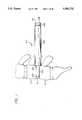
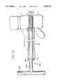
- FIG. 1is a side view of the Long Distractor, of the present invention inserted into the intervertebral space.
- FIG. 4is a perspective view of a spinal segment (two vertebrae and an interposed disc) with a Short Distractor in place, with a portion of the upper vertebrae and disc cut away to show the Short Distractor on one side of the spine and the Long Distractor about to be placed contralaterally.
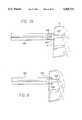
- FIG. 5shows a side view of the Outer Sleeve in place over the Long Distractor, and about to receive the Driver Cap in preparation for being seated.
- FIG. 7Ais a side view of the cervical Outer Sleeve being placed over a Long Distractor which is in place within the disc space anteriorly.
- FIG. 7Eis a bottom view of a Dual Driver Cap for driving two distractors.
- FIG. 7Fis a side sectional view showing the Dual Outer Sleeve of FIGS. 7C and 7D, Distractors and Dual Cap of FIG. 7E seated.
- FIG. 8is a side view of the Outer Sleeve of FIG. 7A centered on the Long Distractor and fully seated on the anterior aspect of the cervical spine.
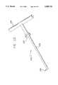
- FIG. 9is a perspective view of the Distractor Puller.
- FIG. 10is a cutaway partial side view of the Proximal Puller engaging the extraction ring of the Long Distractor over the end of the Outer Sleeve.
- FIG. 10Bis a posterior view of the proximal Outer Sleeve and a Short Distractor in place in regard to the vertebrae, disc and nerves.
- FIG. 11Ais a side sectional view of the Drill and Inner Sleeve within the Outer Sleeve and drilling across the intervertebral space and cutting partially cylindrical arcs from the adjacent vertebrae.
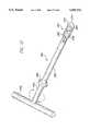
- FIG. 11Dis a side view of an instrument for removing arcs of bone from vertebrae following drilling.
- FIG. 13is a side view of the Outer Sleeve and the surgical Tap fully threaded within the interspace.
- FIG. 14Ais a side view of the bone harvesting Trephine and motor adapter.
- FIG. 14Bis a perspective view of the implant Bone Loading Device.
- FIG. 14Cis a perspective view of the Corkscrew bone freeing and extracting instrument.
- FIG. 15is a partial perspective view of the Bone Loading Device in operation.
- FIG. 16is a perspective view of the Implant Driver about to engage the spinal implant.
- FIG. 17is a side view of the spinal implant being fully seated within the intervertebral space by means of the Driver apparatus in place within the Outer Sleeve.
- FIG. 18is a side view of the lumbar spine showing the end result of the device implantation via the posterior route.
- the method of the present inventioninvolves the following steps.
- the patientis placed on a spinal surgery frame, which allows for the distraction and alignment of the disc space to be fused.
- a bilateral posterior exposure of the interspace, with or without partial discectomyis then performed.
- Utilizing distractorsthe disc space is distracted, and a hollow Outer Sleeve is fitted over one of the distractors.
- the end of the Outer Sleevehas teeth for engaging the two adjacent vertebrae.
- the Outer Sleeveis driven into the vertebrae and the distractor is then removed.
- a hollow Inner Sleeveis then inserted into the Outer Sleeve and a stopped Drill is utilized to prepare the opposed vertebral surfaces.
- the Drill and the Inner Sleeveare removed as a single unit.
- the spaceis tapped if so required.
- the prepared spinal implantis then inserted via the Outer Sleeve utilizing a stopped inserter.
- the instrumentsare then removed and the procedure repeated on the contralateral side of the spine.
- Step 1aPrior to surgery, translucent implant templates appropriately adjusted for scale are superimposed on AP, lateral, and axial images of the interspace to be fused, for the purpose of selecting the optimal implant size and to determine the desired distraction.
- Step 1bThe patient is preferably placed onto a spinal surgery frame capable of inducing both distraction and vertebral alignment.
- Step 2a standard bilateral (partial) discectomy is performed and any posterior lipping of the vertebral bodies adjacent the interspace is removed. Alternatively, no disc material need be removed.
- the interspaceis exposed by performing bilateral paired semihemilaminotomies and resecting the inner aspects of the facet joints adjacent the spinal canal while preserving the supra and interspinous ligaments.
- Step 3Beginning on the first side, the dural sac and traversing nerve root at that level are retracted medially and a Long Distractor then inserted and impacted flush to the posterior vertebral bodies adjacent that interspace. Long Distractors with working ends of increasing diameter are then sequentially inserted until the optimal distraction is obtained.
- This optimal distractionnot only restores the normal height of the interspace, but further achieves a balance wherein the tendency for the space to collapse is resisted, which in urging the vertebral bodies apart is being equally resisted by the powerful soft tissue structures about the spinal segment including the outer casing of the disc (the annulus fibrosus), various ligaments, capsular structures, as well as the muscles and other soft tissue structures.
- This balanced distractionnot only provides for the spatial restoration of the height of the interspace, but for considerable stability as the space now resists further distraction or collapse.
- the use of the solid bodied Long Distractorsis terminated and a disassemblable Convertible Distractor is placed with tactile and/or radiographic confirmation of ideal distraction.
- the Convertible Distractoris then disassembled such that the Short Distractor portion is left in place and the ultra-low profile head portion being positioned adjacent to the canal floor and safely away from the neural structures.
- various embodiments of the Short Distractorare available with varying degrees of resistance to dislodgment. In the preferred embodiment of the procedure, attention is then directed to the contralateral side of the spine.
- Step 4On the contralateral side of the same interspace the Long Distractor having at its working end the diameter matching the Short Distractor already in place, is then inserted. If however, due to an asymmetrical collapse of the interspace it is then determined that greater distraction is required on the second side to achieve the optimal stability, then the appropriate Short Distractor would be placed on the second side. Then the Short Distractor would be removed from the first side and replaced with a larger Long Distractor so as to bring the interspace into balance.
- the entire procedureis performed on the one side of the spine utilizing only the Long Distractor prior to repeating the procedure on the contralateral side of the spine. While this method can be performed in accordance with the remaining steps as described in the preferred embodiment, when utilized it is best performed using a Trephine which allows the Long Distractor to remain in place, thereby allowing for interspace distraction otherwise provided in the first method by the Short Distractor.
- This alternative methodthen requires the use of a Trephine over the Long Distractor in lieu of a reamer and is therefore called the "Trephine Method", which will be discussed in detail later.
- Step 5With the Short Distractor in place on the first side of the spine, and the matching Long Distractor in place on the second side of the spine, and with the dural sac and traversing nerve root safely retracted, the Outer Sleeve is placed over the Long Distractor and firmly impacted to its optimal depth using the Impaction Cap and a mallet. The Long Distractor is then removed.
- Step 7If required, a thread forming Tap with penetration limiting means to control the depth of insertion, is then inserted through the Outer Sleeve.
- Step 8The prepared implant is then inserted utilizing the specialized Driver unit.
- the implantmay be coated with, made of, and/or loaded with substances consistent with bony fusion.
- the implantis treated with bone promoting and inducing substances, but is loaded with materials suitable for participating in a fusion.
- Step 9Using the Driver Extractor instrument, the prepared implant is threaded into the prepared interspace. The instrumentation is removed from that side of the spine and attention is then redirected to the first side of the spine. A small retractor is utilized to move the dural sac and traversing nerve root medially and to protect them and allowing the direct visualization of the retained Short Distractor unit. Without removing the Short Distractor, it is reassembled to its shaft portion, essentially reconstituting itself into a Long Distractor. With the inserted implant now acting as the distractor on the opposite side, the Long Distractor is utilized to guide the Outer Sleeve down where it is impacted as described in Step 5.
- the Long Distractoris then removed and the Inner Sleeve is inserted into the Outer Sleeve. Since the purpose of the Inner Sleeve is to support the drill and allow for the increased size of the implant over the size of the drill, thus making it possible for the insertion of the implant to occur through the Outer Sleeve, the Inner Sleeve therefore measures 18 mm in its outside diameter, and 16.6 mm in its inside diameter. This allows it to fit within the Outer Sleeve, the diameter of which is 18.1 mm and to admit the drill bit which is 16.5 mm in diameter.
- the dural sac and nerve rootare retracted.
- the Outer Sleevehas an inner diameter only slightly greater than the implant to be inserted. Therefore, at this time, a first Inner Sleeve is inserted into the Outer Sleeve to make up the difference between the outside diameter of the Long Distractor and the inside diameter of the Outer Sleeve. With the Outer Sleeve and first Inner Sleeve thus assembled, they are placed over the Long Distractor and the Outer Sleeve is optimally seated using the Impaction Cap. The Cap and first Inner Sleeve are removed, but the Long Distractor and Outer Sleeve are left in place.
- the interspace to be fusedis adequately exposed and the soft tissues and vital structures retracted and protected to either side. Visualization of the broad width of the interspace anteriorly is made possible by the absence of the neurological structures in relation to this aspect of the spine.
- the center line of the anterior aspect of the interspaceis noted and marked.
- the discis removed using first a knife and then curettes and rongeurs as needed. Alternatively, the disc may be left intact to be removed during the drilling stage of the procedure.
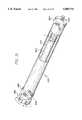
- a Long Distractor 100is inserted under direct vision into the intervertebral space.
- the disc penetrating portion 102is essentially cylindrical with a bullet-shaped front end 103 and a shoulder portion 104 where the penetrating portion 102 extends from barrel 106.
- the penetrating portion 102urges the vertebral bodies apart, facilitating the introduction of the instruments.
- Long Distractors with sequentially increasing diameter penetrating portions 102are then introduced. As the optimal diameter of penetrating portion 102 is achieved, the vertebral bodies to either side are forced into full congruence and thus become parallel, not only to the penetrating portion 102, but to each other.
- FIGS. 3D and 3EA further alternative embodiment is shown in FIGS. 3D and 3E.
- Thisis a more rectangularized design, with forward facing ratchetings, without the sharp prongs 126 of FIG. 3.
- FIG. 3Fis a side view of a further embodiment of the Short Distractor 120 shown with knurling, to increase the interference with the bone surface so as to add stability to the unit and to resist dislodgment.
- the working ends of both the Long and Short Distractorscan have a variety of configurations consistent with their purpose, and that surface irregularities as well as the shape of the ends themselves, with or without prongs 126, may be utilized to make the Short Distractor 120 more resistant to migration.
- the surgeonthen moves to the other side of the spine at the same disc (D) level, and retracts the dural sac and nerve root medially, exposing the disc on that side.
- Long Distractors 100are then sequentially inserted into the disc space until the diameter of the distractor on the second side is at least as big as that on the first side. If because of some asymmetry of the interspace a larger diameter distractor is required on the second side to achieve the ideal distraction as compared to the first side, then the second side is fitted with a Short Distractor of the larger diameter, and the surgeon would then return back to the first side.
- the first side Short Distractorwould then be removed and the Long Distractor 100 corresponding to the increased diameter of the already placed Short Distractor 120 would then be inserted. In either event, the operation is continued by working on the one side where the Long Distractor is in place.
- a deviceas the Michelson Spinal Surgery Frame, it may be possible to obtain adequate distraction preoperatively such that the surgeon is either disinclined to use a distractor, or to simply place the correct Long Distractor on the first side and then proceed with the surgical procedure on that side before moving to the opposite side.
- the Long Distractornow serves as both a centering post and an alignment rod for the hollow Outer Sleeve 140 shown in FIG. 5 which is fitted over the Long Distractor 100, shown by phantom lines 101 in FIG. 5.
- the Outer Sleeve 140is metal and has a sharp toothed front end 142 that is capable of penetrating into and holding fast the two adjacent vertebrae (V). Interrupting the circumferential sharp teeth of 142 are flat, planar areas 152 which serve to resist the further insertion of the sharp teeth into the vertebral bodies.
- the toothed front end 142 of the Outer Sleeve 140is a continuation of the tubular shaft 144, which in turn is connected to circumferentially enlarged tubular back end 146 having a knurled outer surface 148 for easier manipulation.
- An alternative embodiment of an Outer Sleeveincorporates an expansile key hole and slot configuration 154 to either side of shaft 144 along the mid-plane of the interspace and parallel to it such that the end 142 resists the collapse of the vertebrae (V) to either side of the disc (D), but may nevertheless allow for their further distraction, in the event the only diameter or the root diameter of the implant is larger than the hole drilled.
- a Driver Cap 160 in the form of an impaction caphas at its far end a flat, closed-back surface 162 and at its other end a broad, circular opening.
- the Driver Cap 160fits over both the Outer Sleeve 140 and the Long Distractor 100.
- interior surface 170circumferentially engages portion 146 of the Outer Sleeve until the back end 172 engages the internal shoulder 164.
- mallet blowsare applied to surface 162, that force is transmitted via the internal shoulder 164 to the Outer Sleeve 140 via its far end 172, seating teeth 142 into the vertebral bodies adjacent the disc space D and to the depth of the teeth 142 to the flat portions 152.
- the Cap 160is then removed and the Distractor Puller 200 of FIG. 9 utilized to remove the Long Distractor 100 from the spine leaving the Outer Sleeve 140 in place.
- the Distractor Puller 200has front portion 202, a mid portion 204, and a back handle portion 206.
- a socket 208is connected to one end of shaft 210 which at its far end is connected to back handle portion 206.
- the socket 208has defined within it a cavity 212 that is open at its front end and funnelized on the interior aspect of its sides.
- the cavity 212is constructed so that the head of the Distractor Puller 200 and the partially circumferential flange 218 engages the circumferential recess 108 of the Distractor 100.
- the entrance to cavity 212is slightly funnelized, and the leading edges of flange 218 slightly rounded to facilitate the engagement of recess 108 and head 110 of Distractor 100, which is further facilitated in that the Driver Cap 160 leaves portion 108 of Distractor 100 precisely flush with the back surface 172 of the Outer Sleeve 140.
- Thisprovides a large, flat surface 172 to precisely guide surface 230 of socket 208, and open portion 212 around head 110 while flange 218 engages recess 108.
- the springloaded detent ball 228engages hemispherical depression 112 in the crown 110, shown in FIG. 2.
- This springloaded detent 228 in engagement with complimentary indent 218protects against the inadvertent dissociation of the Long Distractor from the Puller 200 after the Distractor has been removed from within the Outer Sleeve 140 and prior to its removal from the wound.
- the two instrumentsare easily disassociated by freeing the crown portion 110 from cavity 212 by a manual force applied perpendicular to their relative long axes at this location.
- a cylindrical and free removable weight 216is fitted around shaft 210 between the front portion 202 and the rear handle portion 206. Gently, but repeatedly sliding the weight 216 along shaft 210 and driven rearwardly against flat surface 228, transmits a rearward vector to proximal end 202 and thereby to the Long Distractor 100 to which it is engaged.
- Paired extended handle 224 and 226,allow the surgeon to resist any excessive rearward motion as the instrument is used to liberate the Long Distractor 100.
- Paired handles 224 and 226are also useful in that they allow a rotational directing of portion 208, via the shaft 210. This allows the surgeon to control and manipulate rotationally the orientation of the opening of cavity 212 to facilitate its application, to the head 110 of the distractor 100.
- the Distractor Puller 200is a significant improvement over the alternatives of striking a remover instrument with an independent hammer over the exposed surgical wound, or manually extracting the distractor by forcefully pulling.
- the use of a free hammer over the open woundis dangerous because the neural structures can be impacted on the back swing which is made even more likely by the effects of gravity on the mallet head.
- Manual extraction by pullingis dangerous because of the significant interference fit of portion 102 within the spine such that significant force would be required to remove the Distractor 100, and if force were not coaxial then the Outer Sleeve might be dislodged or misaligned. Further, once the flat portion 102 became free of the interspace, all resistance to withdrawal would be lost and in the face of the considerable force necessary to free it, the Distractor 100 might easily become projectile imparting injury to the patient and/or the surgeon.
- the toothed end 142 of the Outer Sleeve 140working in conjunction with the Short Distractor 120 on the contralateral side rigidly maintains the relative position of the adjacent vertebrae V. Further, since the remainder of the procedure on that side of the spine occurs entirely through the protective Outer Sleeve 140, and as the nerves and dural sac are external to that Outer Sleeve and superficial to the toothed end 142 of the Outer Sleeve 140, which is firmly embedded into the adjacent vertebrae V, the Outer Sleeve 140 serves to insure the safety of these delicate neural structures.
- the Outer Sleeve 140is of a fixed length and rigid, its flat rearward surface 172 may be used as a stop to the advancement of all instruments placed through the Outer Sleeve 140, thus protecting against accidental overpenetration. Further, the Outer Sleeve 140 assures that the further procedure to be performed will occur coaxial to the disc space D and further, be symmetrical in regard to each of the opposed vertebral surfaces.
- FIG. 10Bis a posterior view of the spine at this stage of the procedure, showing a Short Distractor 120 in place on one side of the spine and the bottom portion of Outer Sleeve 140 in place on the opposite side of the spine.
- an Inner Sleeve 242is inserted from the rear within the Outer Sleeve 140.
- This Inner Sleevehas a collar portion 244 of a known thickness which seats against the top edge surface 172 of Outer Sleeve 140.
- the cylindrical barrel portion of Inner Sleeve 242comes to approximate the posterior aspect of the vertebral bodies interior the Outer Sleeve when fully seated.
- a Drill 240, having a known selected lengthis then introduced through the rearward aperture of the Inner Sleeve 242 and utilized to ream out the arcs of bone which it engages from the opposed vertebral endplates as well as any discal material within its path down to its predetermined and limited depth.
- the Drill 240has a narrow engagement portion 246, which allows it to be affixed to a drill mechanism which may be either a manual or a power unit.
- a circumferential collar 248 of an increased diameterserves to limit the depth of penetration of the drill 240 and may be fixed, or lockably adjustable.
- Such mechanismsinclude, but are not limited to, the use of collets, threaded shafts with lock nuts, and flanges engaging grooves forced therein by either a cap pulled over the flanges or screwed down upon them.
- the forward cutting edge 252 of Drill 240is a modification of a large fluted drill design such that the end resembles an end cutting mill which may contain any workable number of cutting surfaces, but preferably four or more, and such cutting surfaces being relatively shallow such that the advancement of the instrument occurs more slowly.
- the outside diameter of the Drill 240corresponds to the minor diameter of the threaded spinal implant.
- the Inner Sleeve 242has an inner diameter slightly greater than that dimension and its outer diameter is slightly smaller than the inside diameter of the Outer Sleeve 140 which has the same outer diameter as the major diameter of the threaded implant.
- the drill shaft of drill 240comprises an upper portion 243, a central recessed portion 256 of a smaller diameter and a lower cutting drill portion 250.
- the upper portion 243 and lower portion 256 of the drill 240have the same outside diameter.
- a further purpose of the Inner Sleeve 242is that it may be removed simultaneously with the Drill 240, thereby trapping the debris, both cartilaginous and bony generated during the drilling procedure, which are guided rearward by the large flutes 251 of Drill portion 250, where they are collected around recessed portion 256 between the recessed portion 256 and the inner wall of the Inner Sleeve 242 are there contained therein.
- the Drill 240in conjunction with the Inner Sleeve 242, all of the debris generated by the reaming procedure is safely removed from the spinal canal and wound area.
- the disc tissue in the area to be reamedhas been removed previously, as per the preferred method, then the patient's own bone of good quality and useful within the operation will then be contained between the Inner Sleeve 242 and the shaft portion 256. Once away from the surgical wound, this material may be used to load the spinal implant or placed deep within the interspace to participate in the fusion.
- Drill end 250has a forward projecting nipple 260, which itself is bullet-shaped in its leading aspect so as to ease its entrance into the disc space and to urge the vertebrae apart.
- Nipple 260is distracting, stabilizing as it resists any tendency of the vertebrae to move together, is self-centering to the Drill portion 250 when working in conjunction with Sleeves 140 and 242, and virtually assures the symmetrical resection of bone from the opposed vertebral surfaces.
- FIG. 11BThe alternative "Trephine Method" referred to earlier in this application, is shown in FIG. 11B.
- a Long Distractor 100is left in place after the Outer Sleeve 140 is seated.
- the Long Distractor 100in this case differs from the Long Distractor of the preferred embodiment in that its outside diameter of the barrel 106 is of a smaller diameter than in the prior version. This is made necessary because regardless of the method, the hole to be formed corresponds to the minor diameter of the spinal implant.
- Trephine 270a hollow, tubular member with sharp cutting teeth 251 at its proximal end, has a wall thickness and since the outside diameter of that trephine 270 must correspond to the root diameter of the implant, then the wall thickness of the trephine 270 must be allowed for by a corresponding reduction in the diameter of the Long Distractor 100.
- a further modification of the Long Distractor 100 to the "Trephine Method”would use longitudinal grooves (not shown) along the barrel surface 106 for the purpose of transmitting any debris generated during the cutting procedure, rearward. Since the cutting element is both centered and aligned by the Long Distractor, the use of the Inner Sleeve 242 is not mandatory, but may once again be useful in controlling the path of the debris. To that end, little debris is generated in the "Trephine Method" as the bony arcs are not so much being reamed out and removed as they are simply being cut into the bone where these arcs of bone are left connected at their far ends.
- Instrument 272consisting of a shaft 276 attached off center to the lower surface 273 handle 274.
- the shaft 274terminates in a cutting arm 278.
- the instrument 272is inserted through Outer Sleeve 140 where the lower surface 273 of handle 274 abuts the top 172 of the Outer Sleeve 140, both stopping downward motion of instrument 272 and precisely placing the perpendicularly cutting arm 278 of instrument 272 so that as handle portion 274 is rotated, the cutting arm 278 is also rotated, cutting the arcs of bone and liberating them from their last attachments. These portions of bone are then removed utilizing this instrument or a long forceps, and then placed within the implants or otherwise used to participate in the fusion.
- the spinal implant Iis essentially self-tapping, if the bone is unusually hard it may be desirable to form the thread pattern within the interspace prior to the insertion of the implant I.
- Tap 280has a threadcutting portion 282 connected by a shaft 286 to a handle portion 292, which has been designed to give mechanical advantage to the rotation of the instrument for the purpose of cutting threads.
- the lower portion of handle 290has a forward facing flat surface 288 too large to fit through the opening of Outer Sleeve 140 which thus safely limits the depth of penetration of the cutting element 282.
- This tap 280is further made safe by blunt end 294 which will engage the uncut portions of the vertebral bone just prior to the engagement of shoulder 288 against surface 172.
- This featureallows the surgeon to appreciate a less harsh resistance as the blunt nose 294 encounters the remaining unresected bone for the drill hole and prior to the sudden increase in resistance caused by the seating of shoulder 288 against top edge 172, which first resistance serves as a warning to the surgeon to discontinue the tapping procedure.
- the surgeonhas both visual (as shoulder 288 approaches top edge 172) and tactile warnings to avoid stripping the thread form.
- Tap end 282is highly specialized for its specific purpose.
- a truncated bullet-shaped area 298which ramps up to the constant diameter intermediate the cutting ridges 296.
- Ramp portion 298urges the opposed vertebral bodies apart, which motion is resisted by Outer Sleeve 140, thus progressively driving the sharp leading edges of thread forms 296 into the vertebral bodies.
- the periodic longitudinal grooves 284 interrupting the thread formswhich may number 1 to 8, but preferably 4, function to accumulate the bony material which is removed during the thread cutting process. In that regard, in the ideal embodiment, the thread cutting form is designed to compress the bone to be formed rather than to trough through it.
- the major and minor diameters of the Tap 280may be varied, in the preferred embodiment, the minor diameter corresponds to the minor diameter of the implant I, but the major diameter is slightly less than the major diameter of the implant.
- the surgical siteis now fully prepared to receive the spinal implant I.
- the implanthas been enhanced by the use of, application to, and filling with fusion promoting, enhancing, and participating substances and factors.
- the implantmay be fully prepared for insertion as provided to the operating surgeon.
- human boneis most commonly used as the graft material of choice, with the patient's own bone being considered the best source.
- FIG. 14ashows a trephine 300 with an exceedingly sharp front cutting edge 302 for quickly and cleanly coring into the patient's posterior iliac crest, or any other bony tissue, and for the purpose of producing a core of bone then contained within the hollow 304 of the trephine 300.
- Trephine 300has a rear portion 306 with a pair of diametrically opposed slots 310, and disposed clockwise from their longitudinally oriented rearward facing openings so as to engage diametrically and opposing members 312 of Drive unit 308, by which trephine 300 may be attached to either a hand or power drill. It can be appreciated that engagement mechanism 312 is stable during the clockwise cutting procedure, and yet allows for the rapid disconnection of the two components once the cutting is completed.
- a corkscrew 408 shown in FIG. 14Cis introduced though the central opening of rear portion 306 and threaded down and through the core of bone within 304 and to the depth of teeth 302.
- the Trephine 300 with its core of harvested boneis then placed as shown in FIG. 14B, through opening 340 of Implant Bone Loading device 320, where the barrel portion 304 then passes through and is stopped by circular flange 344.
- the plunger shaft 326 of instrument 320is then prepared for attachment by rotating knob 332 counterclockwise such that the plunger 372 is pulled via the long threaded shaft portion 328 back to the base of collar 330 at its proximal end. In this position, knob 332 is considerably extended rearward from collar.330.
- the plunger head 372is inserted into the central hollow of portion 306 of Trephine 300 as the proximal cylindrical portion of collar 330 then follows it, such that the plunger 372 then occupies the rearward portion of barrel 304 and the proximal cylindrical portion of collar 330 occupies the central hollow of portion 306.
- a pair of diametrically opposed radially projecting arms 346 on collar 330are then advanced longitudinally into diametrically opposed paired L slots 340 and then rotated clockwise to complete this assembly.
- a spinal implant Iis engaged through its female rectangular slot 364 by a rectangular protruding bar extending from rearward facing surface of end plug 324, (not shown) and secured there by knob 334 which extends as a rod through a central aperture within end plug 324 to extend at the far end as a small bolt which threads to a female aperture centered within the female slot 364 of the spinal implant.
- end plug 324With the spinal implant I secured to end plug 324 and the opposite end of the implant I presenting as a hollow, tubular opening, end plug 324 is advanced into device 320 where it is secured by rotationally engaging diametrically opposed L-shaped slots 321. With device 320 fully assembled, end 302 of trephine 300 lies coaxial and opposed to the open end of implant I.
- the plunger 372 proximal the threaded shaft 328is then forcibly, but controllably driven forward down the barrel 304 ejecting the bone graft directly into the spinal implant I.
- the bone graftis greater in length than the interior of the spinal implant, with further compression the bone is forced into the radially disposed apertures through the wall of the device communicating from the central cavity to the exterior.
- End plug 324is then removed from apparatus 320. Using end plug 324 as a handle, end cap 374 shown in FIG. 16 is secured to the open end of the spinal implant I. The implant is then disassociated from end plug 324 by rotating knob 334 counterclockwise.
- FIG. 16shows an Implant Driver instrument which may be used to either insert or to remove said implant I.
- Driver 350has at its far end 362, a rectangular protrusion 398, which protrusion intimately engages the complimentary rectangular slot 364 of implant I.
- Protruding from slot 398 of end 362is threaded portion 353, which extends as a rod through hollow shaft 358 and hollow hand barrel 360 to knob 354 where it can be rotationally controlled.
- Threaded portion 353screws into a female aperture central slot 364, urging 353 into 364, and binding them together such that instrument 350 can be rotated via paired and diametrically opposed extending arms 366 and in either direction while maintaining contact with the implant.
- the implantis then introduced through the Outer Sleeve 140 and screwed into the interspace opposed between the two prepared vertebrae V until such time as the leading edge of the Implant Cap 374 reaches the depth of the prepared hole at which time its forward motion is impeded by the bone lying before it which had not been drilled out. This allows for a progressive feel to the surgeon as the implant is screwed home.
- this terminal resistance to further seatingprovides significant tactile feedback to the surgeon.
- visual monitoring of the depth of insertion of the implantis provided to the surgeon by observing the progressive approximation of the forward surface 370, of barrel portion 360, as it approaches the rearward facing surface 172 of Outer Sleeve 140. Nevertheless, a final safety mechanism, when the full depth of insertion has been achieved, surface 370 of instrument 350 will abut surface 172 of the Outer Sleeve 140, prohibiting any further installation of the spinal implant.
- the Driver 350is dissociated from the implant by turning knob 354 in a counterclockwise direction.
- the Driver 350is then withdrawn from the outer sheath, then the Outer Sleeve 140 is removed. This leaves the implant fully installed and inset to the determined depth as shown in FIG. 18.
- a dural nerve root retractoris used to retract the neural structures medially, bringing into full view the head 128 of the Short Distractor 120, lying flush on the canal floor.
- extended screw portion 116is inserted into the female threaded portion 114 of the Short Distractor 120 as the extended rectangular portion 134 of apparatus 152 is engaged to the female rectangular portion 118 of the Short Distractor 120. Then turning rearward facing portions 108 and 110, utilizing the knob 136 of FIG. 2, the Long Distractor configuration is restored.
- the Outer Sleeve 140is slipped over the reconstituted Long Distractor and seated using the Driver Cap 162. The entire sequence of events as described for the implantation of the spinal implant I as already placed, is then repeated such that both spinal implants come to lie side by side within the interspace. Though not necessary, circlage or other internal fixation of the levels to be fused may additionally be performed, and then the wound is closed in the routine manner.
- implantsare placed side by side from anterior to posterior parallel to the interspace and extending through into the adjacent vertebral bodies. Where the transverse width of the disc space is insufficient to allow for the use of two implants, each of which would be large enough to protrude to the required depth into the adjacent vertebrae, then a singular and significantly larger implant may be placed centrally.
- the interspace to be fusedis exposed anteriorly.
- the soft tissuesare withdrawn and protected to either side, and if necessary, above and below as well. It is then possible to visualize the entire width of the vertebrae anteriorly adjacent that interspace.
- the surgeonhas already templated the appropriate patient radiographs to determine the requisite distraction and optimal implant size.
- the surgeonthen broadly excises the great bulk of the nuclear disc portion. (Alternatively, the disc can be left to be removed via the drill later.)
- the surgeonthen notes and marks a point midway from side to side anteriorly. He then inserts Long Distractor 100 centering it on a point midway between the point just noted and the lateral extent of the intervertebral space visualized anteriorly.
- the outer barrel portion 106 of the Distractor 100 utilizedwill correspond to the outside diameter of the implants to be installed.
- the Distractor tips 102 insertedare sequentially larger in diameter until the optimal distraction is achieved.
- This optimal distractionalthough suggested by the initial templating, may be visually and tactilely confirmed as performed.
- the vertebral endplateswill come into full congruence and parallel to the forward shaft portion 102 of the Distractor 100, causing an alteration in the alignment of the vertebrae and a significant increase in the interference fit and pressurization at the tip, such that the instrument becomes exceedingly stable.
- a Dual Outer Sleeve 340consisting of a pair of hollow tubes is then introduced over the side by side Long Distractors protruding anteriorly from the spine.
- the Dual Outer Sleeve 340is comprised of two hollow tubular members identical in size displaced from each other ideally the sum of the difference between the minor and major diameters of both implants combined, but not less than that difference for one implant, as it is possible to have the threads of one implant nest interposed to the threads of the other, such that they both occupy a common area between them.
- the preferred embodimentis slightly greater than two times the difference between the major and minor diameters of the implant (the sum of both) the distance may be considerably greater.
- tubular portions 348 of instrument 340are parallel, when the area between them 350, is sufficiently great, these elements may be inclined or declined relative to each other such that they either converge or diverge at their proximal ends.
- Paired tubular structures 348may be bridged in part or wholly throughout their length, but are rigidly fixed by Foot Plate 344.
- a top viewshows the Foot Plate to be essentially rectangular, but without sharp corners.
- Foot Plate 344is contoured so as to approximate the shape of the vertebrae anteriorly. Extending forward from Foot Plate 344 are multiple sharp prongs 342 sufficiently long to affix them to the vertebrae. The prongs 342 are limited in length so as to not penetrate too far posteriorly and number from 2 to 10, but preferably 6. As the Dual Outer Sleeve 340 is driven forward utilizing Dual Driver Cap 420, of FIG. 7E, engaging the rearward end 352, the prongs 342 extending from Foot Plate 344 are embedded into the opposed vertebral bodies until their forward motion is inhibited by the curved Foot Plate 344 becoming congruent to and being stopped by, the anterior aspect of the vertebral bodies.
- the Dual Driver Cap 420is of the same design as Single Driver Cap 160, in that there is a recess 354 as per 168, allowing the Outer Sleeve to be fully seated without impeding the rearward projection of the Long Distractor unit. However, unlike in Cap 160, area 354 is more relieved as it is unnecessary for the Dual Cap 420 to contact the Long Distractor through portion 110 to inhibit its forward motion, as the Foot Plate 344 functions to that effect. Further, the Dual Cap 420 for the Dual Outer Sleeve 340 is correspondingly dual itself and engages the rearward facing dual tubular portion 352. Once the Dual Outer Sleeve has been fully seated, the vertebrae adjacent the interspace to be fused are rigidly held via Foot Plate 344 and the prongs 342.
- the key element in the anterior methodis the use of the predistraction principle, where such distraction is maintained by the Outer Sleeve with or without the Long Distractor. Therefore, once the preparation of the interspace has been completed, while not the preferred embodiment, it is nevertheless within the scope of this invention that one could remove the Outer Sleeve as there are no neural structures requiring protection, and insert the implants directly rather than through the Outer Sleeve.
- FIGS. 16-18a cylindrical embodiment of the spinal implant I of the present invention is shown.
- the implant Iis shown attached to the insertion device 350.
- the implant Iis shown installed in the disc space D, between the adjacent vertebrae.
- the cylindrical implant Icomprises a hollow tubular member which in the preferred embodiment is made of an ASTM surgically implantable material, preferably Titanium.
- the cylindrical implant Iis closed at one end and open at the other end covered by a cap 394.
- the cylindrical implant Ihas a series of macro-sized openings 390 through the side walls of the cylindrical implant I.
- a series of external threads 392are formed on the circumference of the cylindrical implant I. Any variety of threads may be used on the implant.
- the cap 374has a hexagonal opening 394 for tightening the cap 374.
- While the present inventionhas been described in association with the implant of a threaded spinal implant, it is recognized that other forms of implants may be used with the present method.
- implantsmade from bone or artificial materials, knurled or irregularly shaped cylinders or spheres, or any other shaped implants that can be introduced through the outer sleeve may be used. Being able to perform the procedure through the outer sleeve permits the procedure to be performed safely and quickly, and more accurately.
Landscapes
- Health & Medical Sciences (AREA)
- Engineering & Computer Science (AREA)
- Biomedical Technology (AREA)
- Orthopedic Medicine & Surgery (AREA)
- Life Sciences & Earth Sciences (AREA)
- Animal Behavior & Ethology (AREA)
- Public Health (AREA)
- Surgery (AREA)
- General Health & Medical Sciences (AREA)
- Veterinary Medicine (AREA)
- Oral & Maxillofacial Surgery (AREA)
- Heart & Thoracic Surgery (AREA)
- Neurology (AREA)
- Transplantation (AREA)
- Vascular Medicine (AREA)
- Cardiology (AREA)
- Dentistry (AREA)
- Nuclear Medicine, Radiotherapy & Molecular Imaging (AREA)
- Medical Informatics (AREA)
- Molecular Biology (AREA)
- Physical Education & Sports Medicine (AREA)
- Prostheses (AREA)
- Surgical Instruments (AREA)
Abstract
Description
Claims (4)
Priority Applications (1)
| Application Number | Priority Date | Filing Date | Title |
|---|---|---|---|
| US08/481,750US5505732A (en) | 1988-06-13 | 1995-06-07 | Apparatus and method of inserting spinal implants |
Applications Claiming Priority (6)
| Application Number | Priority Date | Filing Date | Title |
|---|---|---|---|
| US07/205,935US5015247A (en) | 1988-06-13 | 1988-06-13 | Threaded spinal implant |
| US69867491A | 1991-05-10 | 1991-05-10 | |
| US07/968,240US5741253A (en) | 1988-06-13 | 1992-10-29 | Method for inserting spinal implants |
| US08/074,781US5484437A (en) | 1988-06-13 | 1993-06-10 | Apparatus and method of inserting spinal implants |
| US08/396,414US6080155A (en) | 1988-06-13 | 1995-02-27 | Method of inserting and preloading spinal implants |
| US08/481,750US5505732A (en) | 1988-06-13 | 1995-06-07 | Apparatus and method of inserting spinal implants |
Related Parent Applications (1)
| Application Number | Title | Priority Date | Filing Date |
|---|---|---|---|
| US08/074,781DivisionUS5484437A (en) | 1988-06-13 | 1993-06-10 | Apparatus and method of inserting spinal implants |
Publications (1)
| Publication Number | Publication Date |
|---|---|
| US5505732Atrue US5505732A (en) | 1996-04-09 |
Family
ID=27394869
Family Applications (3)
| Application Number | Title | Priority Date | Filing Date |
|---|---|---|---|
| US08/074,781Expired - LifetimeUS5484437A (en) | 1988-06-13 | 1993-06-10 | Apparatus and method of inserting spinal implants |
| US08/481,750Expired - LifetimeUS5505732A (en) | 1988-06-13 | 1995-06-07 | Apparatus and method of inserting spinal implants |
| US08/484,927Expired - LifetimeUS6096038A (en) | 1988-06-13 | 1995-06-07 | Apparatus for inserting spinal implants |
Family Applications Before (1)
| Application Number | Title | Priority Date | Filing Date |
|---|---|---|---|
| US08/074,781Expired - LifetimeUS5484437A (en) | 1988-06-13 | 1993-06-10 | Apparatus and method of inserting spinal implants |
Family Applications After (1)
| Application Number | Title | Priority Date | Filing Date |
|---|---|---|---|
| US08/484,927Expired - LifetimeUS6096038A (en) | 1988-06-13 | 1995-06-07 | Apparatus for inserting spinal implants |
Country Status (3)
| Country | Link |
|---|---|
| US (3) | US5484437A (en) |
| JP (1) | JPH078514A (en) |
| WO (1) | WO1994028824A2 (en) |
Cited By (337)
| Publication number | Priority date | Publication date | Assignee | Title |
|---|---|---|---|---|
| US5658336A (en)* | 1994-03-18 | 1997-08-19 | Pisharodi; Madhavan | Rotating, locking, middle-expanded intervertebral disk stabilizer |
| WO1997037619A1 (en)* | 1996-04-10 | 1997-10-16 | Synthes Ag Chur | Intervertebral implant |
| US5700264A (en)* | 1996-07-01 | 1997-12-23 | Zucherman; James F. | Apparatus and method for preparing a site for an interbody fusion implant |
| WO1998004202A1 (en)* | 1996-07-31 | 1998-02-05 | Michelson Gary K | Milling instrumentation and method for preparing a space between adjacent vertebral bodies |
| US5782832A (en)* | 1996-10-01 | 1998-07-21 | Surgical Dynamics, Inc. | Spinal fusion implant and method of insertion thereof |
| US5800549A (en)* | 1997-04-30 | 1998-09-01 | Howmedica Inc. | Method and apparatus for injecting an elastic spinal implant |
| US5865847A (en)* | 1997-03-06 | 1999-02-02 | Sulzer Spine-Tech Inc. | Lordotic spinal implant |
| US5876457A (en)* | 1997-05-20 | 1999-03-02 | George J. Picha | Spinal implant |
| US5895426A (en)* | 1996-09-06 | 1999-04-20 | Osteotech, Inc. | Fusion implant device and method of use |
| US5895427A (en)* | 1989-07-06 | 1999-04-20 | Sulzer Spine-Tech Inc. | Method for spinal fixation |
| DE19750382A1 (en)* | 1997-11-13 | 1999-05-20 | Augustin Prof Dr Med Betz | Operative correction equipment for displaced vertebrae used in minimally invasive surgery |
| US5913860A (en)* | 1998-02-27 | 1999-06-22 | Synthes (Usa) | Surgical nail inserter |
| US5928243A (en)* | 1997-07-16 | 1999-07-27 | Spinal Concepts, Inc. | Pedicle probe and depth gage |
| US5935133A (en)* | 1997-08-26 | 1999-08-10 | Spinal Concepts, Inc. | Surgical cable system and method |
| US5984922A (en)* | 1993-07-09 | 1999-11-16 | Mckay; Douglas William | Spinal fixation device and method |
| US5989250A (en)* | 1996-10-24 | 1999-11-23 | Spinal Concepts, Inc. | Method and apparatus for spinal fixation |
| WO1999059481A1 (en) | 1998-05-19 | 1999-11-25 | Sulzer Spine-Tech Inc. | Multi-lumen spinal implant guide and method |
| US6004326A (en)* | 1997-09-10 | 1999-12-21 | United States Surgical | Method and instrumentation for implant insertion |
| WO2000003654A2 (en) | 1998-07-16 | 2000-01-27 | Sulzer Spine-Tech Inc. | Apparatus and method for spinal stabilization |
| US6030389A (en)* | 1997-08-04 | 2000-02-29 | Spinal Concepts, Inc. | System and method for stabilizing the human spine with a bone plate |
| US6042582A (en)* | 1997-05-20 | 2000-03-28 | Ray; Charles D. | Instrumentation and method for facilitating insertion of spinal implant |
| US6045579A (en)* | 1997-05-01 | 2000-04-04 | Spinal Concepts, Inc. | Adjustable height fusion device |
| US6053921A (en)* | 1997-08-26 | 2000-04-25 | Spinal Concepts, Inc. | Surgical cable system and method |
| US6063088A (en)* | 1997-03-24 | 2000-05-16 | United States Surgical Corporation | Method and instrumentation for implant insertion |
| US6083225A (en)* | 1996-03-14 | 2000-07-04 | Surgical Dynamics, Inc. | Method and instrumentation for implant insertion |
| US6096038A (en) | 1988-06-13 | 2000-08-01 | Michelson; Gary Karlin | Apparatus for inserting spinal implants |
| US6110210A (en)* | 1999-04-08 | 2000-08-29 | Raymedica, Inc. | Prosthetic spinal disc nucleus having selectively coupled bodies |
| US6113639A (en)* | 1999-03-23 | 2000-09-05 | Raymedica, Inc. | Trial implant and trial implant kit for evaluating an intradiscal space |
| US6113602A (en)* | 1999-03-26 | 2000-09-05 | Sulzer Spine-Tech Inc. | Posterior spinal instrument guide and method |
| WO2000053127A1 (en) | 1999-03-11 | 2000-09-14 | Sulzer Spine-Tech Inc. | Intervertebral disc prosthesis and method |
| US6132430A (en)* | 1996-10-24 | 2000-10-17 | Spinal Concepts, Inc. | Spinal fixation system |
| US6159244A (en)* | 1999-07-30 | 2000-12-12 | Suddaby; Loubert | Expandable variable angle intervertebral fusion implant |
| US6183517B1 (en) | 1998-12-16 | 2001-02-06 | Loubert Suddaby | Expandable intervertebral fusion implant and applicator |
| US6190414B1 (en) | 1996-10-31 | 2001-02-20 | Surgical Dynamics Inc. | Apparatus for fusion of adjacent bone structures |
| US6200322B1 (en)* | 1999-08-13 | 2001-03-13 | Sdgi Holdings, Inc. | Minimal exposure posterior spinal interbody instrumentation and technique |
| WO2001028437A2 (en) | 1999-10-18 | 2001-04-26 | Sulzer Spine-Tech Inc. | Spinal surgery instruments and methods |
| US6224631B1 (en) | 1998-03-20 | 2001-05-01 | Sulzer Spine-Tech Inc. | Intervertebral implant with reduced contact area and method |
| US6245072B1 (en) | 1995-03-27 | 2001-06-12 | Sdgi Holdings, Inc. | Methods and instruments for interbody fusion |
| US6267763B1 (en)* | 1999-03-31 | 2001-07-31 | Surgical Dynamics, Inc. | Method and apparatus for spinal implant insertion |
| US20010012938A1 (en)* | 1997-01-02 | 2001-08-09 | Zucherman James F. | Spine distraction implant |
| WO2001060270A1 (en) | 2000-02-16 | 2001-08-23 | Axiamed, Inc. | Axial spinal implant and apparatus for implanting an axial spinal implant within the vertebrae of the spine |
| US20010020170A1 (en)* | 1997-01-02 | 2001-09-06 | Zucherman James F. | Spinal implants, insertion instruments, and methods of use |
| US6325827B1 (en) | 1999-02-01 | 2001-12-04 | Blacksheep Technologies, Inc. | Intervertebral implant |
| US6332895B1 (en) | 2000-03-08 | 2001-12-25 | Loubert Suddaby | Expandable intervertebral fusion implant having improved stability |
| US6332882B1 (en) | 1997-01-02 | 2001-12-25 | St. Francis Medical Technologies, Inc. | Spine distraction implant |
| WO2002003867A2 (en) | 2000-07-06 | 2002-01-17 | Sulzer Spine-Tech Inc. | Bone preparation instruments |
| US20020026192A1 (en)* | 2000-08-02 | 2002-02-28 | Schmiel Daniel G. | Posterior oblique lumbar arthrodesis |
| US6375655B1 (en) | 1995-03-27 | 2002-04-23 | Sdgi Holdings, Inc. | Interbody fusion device and method for restoration of normal spinal anatomy |
| US6379690B2 (en) | 1997-11-26 | 2002-04-30 | Keraplast Technologies, Ltd. | Keratin-based hydrogel for biomedical applications and method of production |
| US6379355B1 (en) | 1997-01-02 | 2002-04-30 | St. Francis Medical Technologies, Inc. | Spine distraction implant and method |
| US20020058939A1 (en)* | 1997-08-04 | 2002-05-16 | Spinal Concepts, Inc. | System and method for stabilizing the human spine with a bone plate |
| US6428541B1 (en) | 1998-04-09 | 2002-08-06 | Sdgi Holdings, Inc. | Method and instrumentation for vertebral interbody fusion |
| US20020107573A1 (en)* | 1999-03-07 | 2002-08-08 | Discure Ltd. | Method and apparatus for computerized surgery |
| US6436141B2 (en) | 2000-04-07 | 2002-08-20 | Surgical Dynamics, Inc. | Apparatus for fusing adjacent bone structures |
| US20020116066A1 (en)* | 1996-09-13 | 2002-08-22 | Jean-Luc Chauvin | Expandable osteosynthesis cage |
| US6442814B1 (en) | 1999-04-23 | 2002-09-03 | Spinal Concepts, Inc. | Apparatus for manufacturing a bone dowel |
| US6447512B1 (en)* | 2000-01-06 | 2002-09-10 | Spinal Concepts, Inc. | Instrument and method for implanting an interbody fusion device |
| US20020143331A1 (en)* | 1998-10-20 | 2002-10-03 | Zucherman James F. | Inter-spinous process implant and method with deformable spacer |
| US20020161366A1 (en)* | 2000-12-29 | 2002-10-31 | Bruce Robie | Instrument system for preparing a disc space between adjacent vertebral bodies to receive a repair device |
| WO2002094114A1 (en)* | 2001-05-21 | 2002-11-28 | Karl Storz Gmbh & Co. Kg | Manipulator for handling a pedicule screw |
| US20020198533A1 (en)* | 2001-04-17 | 2002-12-26 | Fred Geisler | Multipositional intervertebral instrument guide |
| US20020198532A1 (en)* | 1993-06-10 | 2002-12-26 | Sofamor Danek Holdings, Inc. | Apparatus and method of inserting spinal implants |
| US20030018350A1 (en)* | 2001-07-18 | 2003-01-23 | Zucherman James F. | Curved dilator and method |
| US6514256B2 (en) | 1997-01-02 | 2003-02-04 | St. Francis Medical Technologies, Inc. | Spine distraction implant and method |
| US6520996B1 (en) | 1999-06-04 | 2003-02-18 | Depuy Acromed, Incorporated | Orthopedic implant |
| US20030055503A1 (en)* | 2001-09-19 | 2003-03-20 | O'neil Michael J. | Alignment verification device and method of use |
| US6540753B2 (en) | 2001-03-23 | 2003-04-01 | Howmedica Osteonics Corp. | Instrumentation for implant insertion |
| US20030065330A1 (en)* | 1998-10-20 | 2003-04-03 | St. Francis Medical Technologies, Inc. | Deflectable spacer for use as an interspinous process implant and method |
| US20030083642A1 (en)* | 2001-11-01 | 2003-05-01 | Boyd Lawrence M. | Devices and methods for the restoration of a spinal disc |
| US20030082169A1 (en)* | 2001-11-01 | 2003-05-01 | Boyd Lawrence M. | System and method for the pretreatment of the endplates of an intervertebral disc |
| US6558390B2 (en) | 2000-02-16 | 2003-05-06 | Axiamed, Inc. | Methods and apparatus for performing therapeutic procedures in the spine |
| US6557226B1 (en) | 1999-04-23 | 2003-05-06 | Michael E. Landry | Apparatus for manufacturing a bone dowel |
| US6562041B1 (en) | 1997-08-29 | 2003-05-13 | Sulzer Spine-Tech Inc. | Apparatus and method for spinal stabilization |
| US20030092087A1 (en)* | 2001-11-01 | 2003-05-15 | Walker David H. | Ehrlichia disulfide bond formation proteins and uses thereof |
| US20030097181A1 (en)* | 1999-04-07 | 2003-05-22 | Salvatore Castro | Low profile fusion cage and insertion set |
| US6569168B2 (en) | 2000-05-05 | 2003-05-27 | Osteotech, Inc. | Intervertebral distractor and implant insertion instrument |
| US6575979B1 (en) | 2000-02-16 | 2003-06-10 | Axiamed, Inc. | Method and apparatus for providing posterior or anterior trans-sacral access to spinal vertebrae |
| US6575981B1 (en) | 1999-02-04 | 2003-06-10 | Sdgi Holdings, Inc. | Methods and instrumentation for vertebral interbody fusion |
| US6582433B2 (en) | 2001-04-09 | 2003-06-24 | St. Francis Medical Technologies, Inc. | Spine fixation device and method |
| US6582437B2 (en) | 1999-08-26 | 2003-06-24 | Sdgi Holdings, Inc. | Devices and methods for implanting fusion cages |
| US20030120273A1 (en)* | 2001-12-21 | 2003-06-26 | Cole J. Dean | Surgical distractor frame |
| US6599291B1 (en)* | 2000-10-20 | 2003-07-29 | Sdgi Holdings, Inc. | Methods and instruments for interbody surgical techniques |
| US6599320B1 (en) | 1993-02-10 | 2003-07-29 | Sulzer Spine-Tech Inc. | Alignment guide assembly for spinal stabilization |
| US6635086B2 (en) | 2000-05-30 | 2003-10-21 | Blacksheep Technologies Incorporated | Implant for placement between cervical vertebrae |
| US6648895B2 (en) | 2000-02-04 | 2003-11-18 | Sdgi Holdings, Inc. | Methods and instrumentation for vertebral interbody fusion |
| US6652527B2 (en) | 1998-10-20 | 2003-11-25 | St. Francis Medical Technologies, Inc. | Supplemental spine fixation device and method |
| US6652533B2 (en) | 2001-09-20 | 2003-11-25 | Depuy Acromed, Inc. | Medical inserter tool with slaphammer |
| US6652534B2 (en) | 1998-10-20 | 2003-11-25 | St. Francis Medical Technologies, Inc. | Apparatus and method for determining implant size |
| US6682534B2 (en) | 2001-08-02 | 2004-01-27 | Depuy Acromed, Inc. | Endplate preparation instrument and associated method |
| US20040019354A1 (en)* | 2001-03-08 | 2004-01-29 | Wes Johnson | Tissue distraction device |
| US6695842B2 (en) | 1997-10-27 | 2004-02-24 | St. Francis Medical Technologies, Inc. | Interspinous process distraction system and method with positionable wing and method |
| US6699246B2 (en) | 1997-01-02 | 2004-03-02 | St. Francis Medical Technologies, Inc. | Spine distraction implant |
| US20040044411A1 (en)* | 2002-08-30 | 2004-03-04 | Loubert Suddaby | Lordotic fusion implant |
| US20040044409A1 (en)* | 1999-12-30 | 2004-03-04 | Alfaro Arthur A. | Intervertebral implants |
| US6709439B2 (en) | 2001-10-30 | 2004-03-23 | Depuy Spine, Inc. | Slaphammer tool |
| US6712819B2 (en) | 1998-10-20 | 2004-03-30 | St. Francis Medical Technologies, Inc. | Mating insertion instruments for spinal implants and methods of use |
| US6740090B1 (en) | 2000-02-16 | 2004-05-25 | Trans1 Inc. | Methods and apparatus for forming shaped axial bores through spinal vertebrae |
| US6743234B2 (en) | 1999-02-04 | 2004-06-01 | Sdgi Holdings, Inc. | Methods and instrumentation for vertebral interbody fusion |
| US6746485B1 (en) | 1999-02-18 | 2004-06-08 | St. Francis Medical Technologies, Inc. | Hair used as a biologic disk, replacement, and/or structure and method |
| US6755841B2 (en) | 2000-05-08 | 2004-06-29 | Depuy Acromed, Inc. | Medical installation tool |
| US20040126557A1 (en)* | 2000-12-07 | 2004-07-01 | Lothar Thiele | Stone composite slabs |
| US20040138750A1 (en)* | 2002-10-29 | 2004-07-15 | St. Francis Medical Technologies, Inc. | Artificial vertebral disk replacement implant with a spacer and method |
| US20040143270A1 (en)* | 2002-10-29 | 2004-07-22 | St. Francis Medical Technologies, Inc. | Tools for implanting artificial vertebral disk and method |
| US6770074B2 (en) | 1988-06-13 | 2004-08-03 | Gary Karlin Michelson | Apparatus for use in inserting spinal implants |
| US20040153065A1 (en)* | 2003-02-03 | 2004-08-05 | Lim Roy K. | Expanding interbody implant and articulating inserter and method |
| US20040162618A1 (en)* | 2003-02-14 | 2004-08-19 | Centerpulse Spine-Tech, Inc. | Expandable intervertebral implant cage |
| US6780192B2 (en) | 2000-10-24 | 2004-08-24 | Sdgi Holdings, Inc. | Osteogenic packing device and method |
| US6783546B2 (en) | 1999-09-13 | 2004-08-31 | Keraplast Technologies, Ltd. | Implantable prosthetic or tissue expanding device |
| US20040176764A1 (en)* | 2003-03-03 | 2004-09-09 | Centerpulse Spine-Tech, Inc. | Apparatus and method for spinal distraction using a flip-up portal |
| US20040181282A1 (en)* | 2002-10-29 | 2004-09-16 | Zucherman James F. | Interspinous process apparatus and method with a selectably expandable spacer |
| US20040186483A1 (en)* | 2003-03-22 | 2004-09-23 | Bagby George W. | Implant driver apparatus and bone joining device |
| US6796983B1 (en) | 1997-01-02 | 2004-09-28 | St. Francis Medical Technologies, Inc. | Spine distraction implant and method |
| US6821280B1 (en) | 2000-08-03 | 2004-11-23 | Charanpreet S. Bagga | Distracting and curetting instrument |
| US20050010296A1 (en)* | 2002-10-29 | 2005-01-13 | St. Francis Medical Technologies, Inc. | Artificial vertebral disk replacement implant with crossbar spacer and method |
| US20050010298A1 (en)* | 2003-05-22 | 2005-01-13 | St. Francis Medical Technologies, Inc. | Cervical interspinous process distraction implant and method of implantation |
| US20050021042A1 (en)* | 2003-07-21 | 2005-01-27 | Theirry Marnay | Instruments and method for inserting an intervertebral implant |
| US6849092B2 (en) | 1999-09-13 | 2005-02-01 | Keraplast Technologies, Ltd. | Implantable prosthetic or tissue expanding device |
| US20050075643A1 (en)* | 2002-10-08 | 2005-04-07 | Schwab Frank J. | Insertion device and techniques for orthopaedic implants |
| US20050107880A1 (en)* | 2001-12-05 | 2005-05-19 | Osteotech, Inc. | Spinal intervertebral implant, interconnections for such implant and processes for making |
| US6899734B2 (en) | 2001-03-23 | 2005-05-31 | Howmedica Osteonics Corp. | Modular implant for fusing adjacent bone structure |
| US6899716B2 (en) | 2000-02-16 | 2005-05-31 | Trans1, Inc. | Method and apparatus for spinal augmentation |
| US20050125065A1 (en)* | 2003-11-05 | 2005-06-09 | St. Francis Medical Technologies Inc. | Laterally insertable artificial vertebral disk replacement implant with crossbar spacer |
| US20050137612A1 (en)* | 2003-10-23 | 2005-06-23 | Assell Robert L. | Access assembly for guiding instrumentation through soft tissue to a point on the spine |
| US20050143826A1 (en)* | 2003-12-11 | 2005-06-30 | St. Francis Medical Technologies, Inc. | Disk repair structures with anchors |
| US20050143749A1 (en)* | 2003-12-31 | 2005-06-30 | Depuy Spine, Inc. | Inserter instrument and implant clip |
| US20050143740A1 (en)* | 2000-10-20 | 2005-06-30 | Morris John W. | Implant retaining device |
| US20050149188A1 (en)* | 2002-02-07 | 2005-07-07 | Cook Stephen D. | Anterior spinal implant |
| US20050149193A1 (en)* | 2003-11-20 | 2005-07-07 | St. Francis Medical Technology, Inc. | Intervertebral body fusion cage with keels and implantation methods |
| US20050149192A1 (en)* | 2003-11-20 | 2005-07-07 | St. Francis Medical Technologies, Inc. | Intervertebral body fusion cage with keels and implantation method |
| US20050154462A1 (en)* | 2003-12-02 | 2005-07-14 | St. Francis Medical Technologies, Inc. | Laterally insertable artificial vertebral disk replacement implant with translating pivot point |
| US20050165408A1 (en)* | 2004-01-26 | 2005-07-28 | Puno Rolando M. | Methods and instrumentation for inserting intervertebral grafts and devices |
| US6929647B2 (en) | 2001-02-21 | 2005-08-16 | Howmedica Osteonics Corp. | Instrumentation and method for implant insertion |
| US20050182414A1 (en)* | 2004-01-08 | 2005-08-18 | Richard Manzi | Apparatus and method for injecting fluent material at a distracted tissue site |
| US20050196420A1 (en)* | 2003-12-02 | 2005-09-08 | St. Francis Medical Technologies, Inc. | Bioresorbable interspinous process implant for use with intervertebral disk remediation or replacement implants and procedures |
| US20050197702A1 (en)* | 2002-08-15 | 2005-09-08 | Coppes Justin K. | Intervertebral disc implant |
| US20050216027A1 (en)* | 2004-03-24 | 2005-09-29 | Suh Sean S | Extraction screwdriver |
| US20050216088A1 (en)* | 1998-05-27 | 2005-09-29 | Nu Vasive, Inc. | Bone blocks and methods for inserting bone blocks into intervertebral spaces |
| US20050234455A1 (en)* | 2004-04-19 | 2005-10-20 | Lawrence Binder | Bone fixation plate |
| US20050240197A1 (en)* | 2004-04-23 | 2005-10-27 | Kmiec Stanley J Jr | Device and method for inserting, positioning and removing an implant |
| US20050240182A1 (en)* | 1997-01-02 | 2005-10-27 | St. Francis Medical Technologies, Inc. | Supplemental spine fixation device and method |
| US20050245929A1 (en)* | 2004-04-28 | 2005-11-03 | St. Francis Medical Technologies, Inc. | System and method for an interspinous process implant as a supplement to a spine stabilization implant |
| US6964664B2 (en) | 2000-01-06 | 2005-11-15 | Spinal Concepts Inc. | System and method for stabilizing the human spine with a bone plate |
| US20050261695A1 (en)* | 2000-02-16 | 2005-11-24 | Cragg Andrew H | Method and apparatus for spinal distraction and fusion |
| US20050267581A1 (en)* | 1999-07-02 | 2005-12-01 | Thierry Marnay | Intervertebral Implant |
| US20050273111A1 (en)* | 1999-10-08 | 2005-12-08 | Ferree Bret A | Methods and apparatus for intervertebral disc removal and endplate preparation |
| US20050283237A1 (en)* | 2003-11-24 | 2005-12-22 | St. Francis Medical Technologies, Inc. | Artificial spinal disk replacement device with staggered vertebral body attachments |
| US20050283242A1 (en)* | 2003-11-21 | 2005-12-22 | St. Francis Medical Technologies, Inc. | Laterally insertable artificial vertebral disk replacement implant with curved spacer |
| US20060009851A1 (en)* | 2004-06-29 | 2006-01-12 | Keith Collins | Percutaneous methods for injecting a curable biomaterial into an intervertebral space |
| US20060020342A1 (en)* | 2004-07-21 | 2006-01-26 | Ferree Bret A | Facet-preserving artificial disc replacements |
| US20060025778A1 (en)* | 2004-07-21 | 2006-02-02 | Ferree Bret A | Methods and apparatus for artificial disc replacement (ADR) insertion and other surgical procedures |
| US20060030857A1 (en)* | 2004-08-06 | 2006-02-09 | Spinalmotion, Inc. | Methods and apparatus for intervertebral disc prosthesis insertion |
| US20060036258A1 (en)* | 2004-06-08 | 2006-02-16 | St. Francis Medical Technologies, Inc. | Sizing distractor and method for implanting an interspinous implant between adjacent spinous processes |
| US20060052793A1 (en)* | 2004-08-20 | 2006-03-09 | Heinz Eric S | Instrumentation and methods for vertebral distraction |
| US20060058807A1 (en)* | 2004-08-25 | 2006-03-16 | Michael Landry | Expandable interbody fusion device |
| US20060064166A1 (en)* | 2004-09-23 | 2006-03-23 | St. Francis Medical Technologies, Inc. | Interspinous process implant including a binder and method of implantation |
| US20060069439A1 (en)* | 2004-09-29 | 2006-03-30 | St. Francis Medical Technologies, Inc. | Artificial vertebral disk replacement implant with translating articulation contact surface and method |
| US20060069440A1 (en)* | 2004-09-29 | 2006-03-30 | Zucherman James F | Multi-piece artificial spinal disk replacement device with selectably positioning articulating element |
| US20060069438A1 (en)* | 2004-09-29 | 2006-03-30 | Zucherman James F | Multi-piece artificial spinal disk replacement device with multi-segmented support plates |
| US20060084986A1 (en)* | 2004-09-30 | 2006-04-20 | Depuy Spine, Inc. | Instrument and method for the insertion and alignment of an intervertebral implant |
| US20060084992A1 (en)* | 1988-06-13 | 2006-04-20 | Michelson Gary K | Tubular member having a passage and opposed bone contacting extensions |
| US20060085077A1 (en)* | 2004-10-18 | 2006-04-20 | Ebi, L.P. | Intervertebral implant and associated method |
| US20060089649A1 (en)* | 2004-10-26 | 2006-04-27 | Ullrich Peter F Jr | Surgical instruments and method of using same |
| US20060089718A1 (en)* | 2003-05-22 | 2006-04-27 | St. Francis Medical Technologies, Inc. | Interspinous process implant and method of implantation |
| US20060106381A1 (en)* | 2004-11-18 | 2006-05-18 | Ferree Bret A | Methods and apparatus for treating spinal stenosis |
| US20060111782A1 (en)* | 2004-11-22 | 2006-05-25 | Orthopedic Development Corporation | Spinal plug for a minimally invasive facet joint fusion system |
| US20060149300A1 (en)* | 2004-10-22 | 2006-07-06 | Jessen John W | Vasectomy tool |
| US20060149373A1 (en)* | 2004-12-13 | 2006-07-06 | St. Francis Medical Technologies, Inc. | Inter-cervical facet implant and method |
| US20060149239A1 (en)* | 2004-12-13 | 2006-07-06 | St. Francis Medical Technologies, Inc. | Inter-cervical facet implant with locking screw and method |
| US7083649B2 (en) | 2002-10-29 | 2006-08-01 | St. Francis Medical Technologies, Inc. | Artificial vertebral disk replacement implant with translating pivot point |
| US7118580B1 (en) | 1999-09-14 | 2006-10-10 | Spine Solutions Inc. | Instrument for inserting intervertebral implants |
| US20060229629A1 (en)* | 2003-05-16 | 2006-10-12 | Spine Wave, Inc. | Tissue distraction device |
| US20060241641A1 (en)* | 2005-04-22 | 2006-10-26 | Sdgi Holdings, Inc. | Methods and instrumentation for distraction and insertion of implants in a spinal disc space |
| US20060247778A1 (en)* | 2005-01-26 | 2006-11-02 | Ferree Bret A | Intradiscal devices including spacers facilitating posterior-lateral and other insertion approaches |
| US20060264957A1 (en)* | 2000-02-16 | 2006-11-23 | Trans1, Inc. | Apparatus for performing a discectomy through a trans-sacral axial bore within the vertebrae of the spine |
| US20060271194A1 (en)* | 2005-03-22 | 2006-11-30 | St. Francis Medical Technologies, Inc. | Interspinous process implant having deployable wing as an adjunct to spinal fusion and method of implantation |
| US20070055379A1 (en)* | 2005-08-03 | 2007-03-08 | Stone Corbett W | Annular access devices |
| US20070055260A1 (en)* | 2003-06-10 | 2007-03-08 | Cragg Andrew H | Method and apparatus for providing posterior or anterior trans-sacral access to spinal vertebrae |
| US7189234B2 (en) | 1998-10-20 | 2007-03-13 | St. Francis Medical Technologies, Inc. | Interspinous process implant sizer and distractor with a split head and size indicator and method |
| US20070061011A1 (en)* | 2002-09-19 | 2007-03-15 | Spinalmotion, Inc. | Intervertebral Prosthesis |
| US20070066977A1 (en)* | 2004-10-22 | 2007-03-22 | Assell Robert L | Exchange system for axial spinal procedures |
| US20070073398A1 (en)* | 2005-09-27 | 2007-03-29 | Fabian Henry F | Spine surgery method and implant |
| US20070093841A1 (en)* | 2005-09-23 | 2007-04-26 | Thomas Hoogland | Surgical drill, a set of surgical drills, a system for cutting bone and a method for removing bone |
| US20070100347A1 (en)* | 2005-10-31 | 2007-05-03 | Stad Shawn D | Arthroplasty revision device and method |
| US20070106316A1 (en)* | 2005-10-10 | 2007-05-10 | University Of South Florida | Dural Knife with Foot Plate |
| US20070123904A1 (en)* | 2005-10-31 | 2007-05-31 | Depuy Spine, Inc. | Distraction instrument and method for distracting an intervertebral site |
| US20070123903A1 (en)* | 2005-10-31 | 2007-05-31 | Depuy Spine, Inc. | Medical Device installation tool and methods of use |
| US20070162040A1 (en)* | 2005-12-06 | 2007-07-12 | Zimmer Spine, Inc. | Spinal distraction and endplate preparation device and method |
| US20070162134A1 (en)* | 2002-12-13 | 2007-07-12 | Theirry Marnay | Intervertebral implant, insertion tool and method of inserting same |
| US20070185375A1 (en)* | 2006-02-06 | 2007-08-09 | Depuy Spine, Inc. | Medical device installation tool |
| US20070208346A1 (en)* | 2003-04-28 | 2007-09-06 | Theirry Marnay | Instruments and method for preparing an intervertebral space for receiving an artificial disc implant |
| US20070233153A1 (en)* | 2006-03-17 | 2007-10-04 | Sdgi Holdings, Inc. | Instrumentation for distraction and insertion of implants in a spinal disc space |
| US20070233260A1 (en)* | 2000-02-16 | 2007-10-04 | Trans1 Inc. | Articulating spinal implant |
| US20070288092A1 (en)* | 2006-06-01 | 2007-12-13 | Bambakidis Nicholas | Expandable intervertebral implant and method |
| US20070299521A1 (en)* | 2004-11-23 | 2007-12-27 | Glenn Bradley J | Minimally invasive spinal disc stabilizer and insertion tool |
| US20080015694A1 (en)* | 2006-01-13 | 2008-01-17 | Clifford Tribus | Spine reduction and stabilization device |
| US7335203B2 (en) | 2003-02-12 | 2008-02-26 | Kyphon Inc. | System and method for immobilizing adjacent spinous processes |
| US20080065076A1 (en)* | 2000-02-16 | 2008-03-13 | Cragg Andrew H | Spinal mobility preservation apparatus |
| US20080071281A1 (en)* | 2006-09-08 | 2008-03-20 | Spine Wave Inc. | Modular Injection Needle and Seal Assembly |
| US20080108990A1 (en)* | 2006-11-02 | 2008-05-08 | St. Francis Medical Technologies, Inc. | Interspinous process implant having a fixed wing and a deployable wing and method of implantation |
| US20080167655A1 (en)* | 2007-01-05 | 2008-07-10 | Jeffrey Chun Wang | Interspinous implant, tools and methods of implanting |
| US20080287957A1 (en)* | 2007-05-18 | 2008-11-20 | Depuy Spine, Inc. | Insertion blade assembly and method of use |
| US20080300601A1 (en)* | 2007-05-31 | 2008-12-04 | Fabian Henry F | Spine surgery method and instrumentation |
| US20080300598A1 (en)* | 2007-05-31 | 2008-12-04 | Spine Wave, Inc. | Expandable Interbody Fusion Device |
| US20090018658A1 (en)* | 2006-08-09 | 2009-01-15 | Nuvasive, Inc. | Methods and apparatus for treating spinal stenosis |
| US20090036927A1 (en)* | 2007-05-22 | 2009-02-05 | Tov Vestgaarden | Method and apparatus for spinal facet fusion |
| US20090043340A1 (en)* | 2007-08-07 | 2009-02-12 | Holland Surgical Innovations, Inc. | Implantable bone plate system and related method for spinal repair |
| US20090062918A1 (en)* | 2007-08-30 | 2009-03-05 | Jeffrey Chun Wang | Interspinous implant, tools and methods of implanting |
| US20090062916A1 (en)* | 2007-08-27 | 2009-03-05 | Biomedical Enterprises, Inc. | Method and apparatus for an osteotomy fixation or arthrodesis cage |
| US20090076551A1 (en)* | 2004-11-22 | 2009-03-19 | Petersen David A | Methods and surgical kits for minimally-invasive facet joint fusion |
| US20090076516A1 (en)* | 2007-09-13 | 2009-03-19 | David Lowry | Device and method for tissue retraction in spinal surgery |
| US20090076614A1 (en)* | 2007-09-17 | 2009-03-19 | Spinalmotion, Inc. | Intervertebral Prosthetic Disc with Shock Absorption Core |
| US20090076555A1 (en)* | 2007-09-13 | 2009-03-19 | David Lowry | Transcorporeal spinal decompression and repair system and related method |
| US20090088604A1 (en)* | 2007-09-28 | 2009-04-02 | David Lowry | Vertebrally-mounted tissue retractor and method for use in spinal surgery |
| US20090099568A1 (en)* | 2007-08-07 | 2009-04-16 | David Lowry | Device and method for variably adjusting intervertebral distraction and lordosis |
| USD590943S1 (en)* | 2008-01-29 | 2009-04-21 | Orthopedic Development Corporation | Surgical bone plug inserter |
| US7547317B2 (en) | 2000-02-16 | 2009-06-16 | Trans1 Inc. | Methods of performing procedures in the spine |
| US20090177205A1 (en)* | 2008-01-09 | 2009-07-09 | Providence Medical Technology, Inc. | Methods and apparatus for accessing and treating the facet joint |
| USD599479S1 (en)* | 2009-03-13 | 2009-09-01 | Orthopedic Development Corporation | Surgical inserter |
| US20090234458A1 (en)* | 2008-03-11 | 2009-09-17 | Spinalmotion, Inc. | Artificial Intervertebral Disc With Lower Height |
| US20090240280A1 (en)* | 2008-03-19 | 2009-09-24 | Jeffrey Chun Wang | Interspinous implant, tools and methods of implanting |
| US20090270873A1 (en)* | 2008-04-24 | 2009-10-29 | Fabian Henry F | Spine surgery method and inserter |
| US20090306671A1 (en)* | 2008-06-06 | 2009-12-10 | Providence Medical Technology, Inc. | Facet joint implants and delivery tools |
| US20090312763A1 (en)* | 2008-06-06 | 2009-12-17 | Mccormack Bruce M | Facet joint implants and delivery tools |
| US7637952B2 (en) | 2002-03-11 | 2009-12-29 | Zimmer Spine, Inc. | Instrumentation and procedure for implanting spinal implant devices |
| US20100023128A1 (en)* | 2008-07-23 | 2010-01-28 | Malberg Marc I | Modular nucleus pulposus prosthesis |
| US20100049326A1 (en)* | 2007-02-12 | 2010-02-25 | Petersen Kenneth C | Joint revision implant |
| US20100076443A1 (en)* | 2006-07-31 | 2010-03-25 | Rudolph Bertagnoli | Drilling/milling guide and keel cut preparation system |
| US7736380B2 (en) | 2004-12-21 | 2010-06-15 | Rhausler, Inc. | Cervical plate system |
| US20100152784A1 (en)* | 2007-08-07 | 2010-06-17 | David Lowry | Implantable vertebral frame systems and related methods for spinal repair |
| US20100168860A1 (en)* | 2008-12-22 | 2010-07-01 | Marc Reichen | Orthopedic implant with flexible keel |
| US7749252B2 (en) | 2005-03-21 | 2010-07-06 | Kyphon Sarl | Interspinous process implant having deployable wing and method of implantation |
| US7753911B2 (en) | 1998-04-09 | 2010-07-13 | Warsaw Orthopedic, Inc. | Methods and instrumentation for vertebral interbody fusion |
| US20100179655A1 (en)* | 2009-01-12 | 2010-07-15 | Noah Hansell | Expandable Vertebral Prosthesis |
| US7766947B2 (en) | 2001-10-31 | 2010-08-03 | Ortho Development Corporation | Cervical plate for stabilizing the human spine |
| US7776046B2 (en) | 1998-04-09 | 2010-08-17 | Warsaw Orthopedic, Inc. | Method and instrumentation for vertebral interbody fusion |
| US7780676B2 (en) | 2006-07-11 | 2010-08-24 | Ebi, Llc | Intervertebral implantation apparatus |
| US20100249795A1 (en)* | 2009-03-30 | 2010-09-30 | Dimauro Thomas M | Cervical Motion Disc Inserter |
| US7824431B2 (en) | 2006-12-29 | 2010-11-02 | Providence Medical Technology, Inc. | Cervical distraction method |
| US7833246B2 (en) | 2002-10-29 | 2010-11-16 | Kyphon SÀRL | Interspinous process and sacrum implant and method |
| US20100292742A1 (en)* | 2009-05-13 | 2010-11-18 | Stad Shawn D | Torque Limited Instrument For Manipulating A Spinal Rod Relative to a Bone Anchor |
| US20100292700A1 (en)* | 2009-05-12 | 2010-11-18 | Wolfgang Ries | Spine cutter |
| USD627885S1 (en)* | 2009-07-22 | 2010-11-23 | Brannon James K | Trephine |
| US20100298942A1 (en)* | 2005-04-21 | 2010-11-25 | Noah Hansell | Expandable Vertebral Prosthesis |
| US20110054548A1 (en)* | 2009-09-03 | 2011-03-03 | Zimmer Spine, Inc. | Spinal implant delivery methods and devices |
| US20110098746A1 (en)* | 2005-12-06 | 2011-04-28 | Nuvasive, Inc. | Methods and Apparatus For Treating Spinal Stenosis |
| US20110112373A1 (en)* | 2009-11-10 | 2011-05-12 | Trans1 Inc. | Soft tissue access apparatus and methods for spinal surgery |
| US7959652B2 (en) | 2005-04-18 | 2011-06-14 | Kyphon Sarl | Interspinous process implant having deployable wings and method of implantation |
| US8002834B2 (en) | 2004-07-30 | 2011-08-23 | Spinalmotion, Inc. | Intervertebral prosthetic disc with metallic core |
| US8012209B2 (en) | 2004-09-23 | 2011-09-06 | Kyphon Sarl | Interspinous process implant including a binder, binder aligner and method of implantation |
| US8070778B2 (en) | 2003-05-22 | 2011-12-06 | Kyphon Sarl | Interspinous process implant with slide-in distraction piece and method of implantation |
| US8083797B2 (en) | 2005-02-04 | 2011-12-27 | Spinalmotion, Inc. | Intervertebral prosthetic disc with shock absorption |
| US8090428B2 (en) | 2003-01-31 | 2012-01-03 | Spinalmotion, Inc. | Spinal midline indicator |
| US8092538B2 (en) | 2003-05-27 | 2012-01-10 | Spinalmotion, Inc. | Intervertebral prosthetic disc |
| US8163021B2 (en) | 2007-11-27 | 2012-04-24 | Transcorp, Inc. | Methods and systems for repairing an intervertebral disc using a transcorporal approach |
| US8167915B2 (en) | 2005-09-28 | 2012-05-01 | Nuvasive, Inc. | Methods and apparatus for treating spinal stenosis |
| US8206449B2 (en) | 2008-07-17 | 2012-06-26 | Spinalmotion, Inc. | Artificial intervertebral disc placement system |
| US8236034B2 (en) | 2004-04-19 | 2012-08-07 | Globus Medical, Inc. | Bone fixation plate |
| US8313528B1 (en) | 2008-03-27 | 2012-11-20 | Spinelogik, Inc. | Intervertebral fusion device and method of use |
| US8333985B2 (en) | 2004-01-27 | 2012-12-18 | Warsaw Orthopedic, Inc. | Non-glycerol stabilized bone graft |
| US8333804B1 (en) | 2008-03-27 | 2012-12-18 | Spinelogik, Inc. | Intervertebral fusion device and method of use |
| US20130035729A1 (en)* | 2011-08-02 | 2013-02-07 | Blackstone Medical, Inc. | Bayonet counter-torque wrench |
| US8425530B2 (en) | 2004-12-13 | 2013-04-23 | Warsaw Orthopedic, Inc. | Apparatus for sizing a facet joint |
| US8425569B2 (en) | 2010-05-19 | 2013-04-23 | Transcorp, Inc. | Implantable vertebral frame systems and related methods for spinal repair |
| US8430882B2 (en) | 2007-09-13 | 2013-04-30 | Transcorp, Inc. | Transcorporeal spinal decompression and repair systems and related methods |
| US8435301B2 (en) | 2002-08-15 | 2013-05-07 | DePuy Synthes Products, LLC | Artificial intervertebral disc implant |
| US20130158596A1 (en)* | 2011-12-16 | 2013-06-20 | Depuy Mitek, Inc. | Methods and systems for attaching tissue to bone |
| US8480715B2 (en) | 2007-05-22 | 2013-07-09 | Zimmer Spine, Inc. | Spinal implant system and method |
| US8486147B2 (en) | 2006-04-12 | 2013-07-16 | Spinalmotion, Inc. | Posterior spinal device and method |
| US8506631B2 (en) | 2007-08-09 | 2013-08-13 | Spinalmotion, Inc. | Customized intervertebral prosthetic disc with shock absorption |
| US8512347B2 (en) | 2008-06-06 | 2013-08-20 | Providence Medical Technology, Inc. | Cervical distraction/implant delivery device |
| US8623088B1 (en) | 2005-07-15 | 2014-01-07 | Nuvasive, Inc. | Spinal fusion implant and related methods |
| US8685035B2 (en) | 2003-01-31 | 2014-04-01 | Spinalmotion, Inc. | Intervertebral prosthesis placement instrument |
| US8715351B1 (en) | 2012-11-29 | 2014-05-06 | Spine Wave, Inc. | Expandable interbody fusion device with graft chambers |
| US8721722B2 (en) | 2004-10-18 | 2014-05-13 | Ebi, Llc | Intervertebral implant and associated method |
| US8734447B1 (en) | 1988-06-13 | 2014-05-27 | Warsaw Orthopedic, Inc. | Apparatus and method of inserting spinal implants |
| US8758441B2 (en) | 2007-10-22 | 2014-06-24 | Spinalmotion, Inc. | Vertebral body replacement and method for spanning a space formed upon removal of a vertebral body |
| US8808294B2 (en) | 2008-09-09 | 2014-08-19 | William Casey Fox | Method and apparatus for a multiple transition temperature implant |
| US8828019B1 (en) | 2013-03-13 | 2014-09-09 | Spine Wave, Inc. | Inserter for expanding an expandable interbody fusion device |
| US8845730B2 (en) | 2008-07-18 | 2014-09-30 | Simplify Medical, Inc. | Posterior prosthetic intervertebral disc |
| US8900312B2 (en) | 2013-03-12 | 2014-12-02 | Spine Wave, Inc. | Expandable interbody fusion device with graft chambers |
| US8998990B2 (en) | 2006-07-24 | 2015-04-07 | DePuy Synthes Products, LLC | Intervertebral implant with keel |
| US9011544B2 (en) | 2008-05-05 | 2015-04-21 | Simplify Medical, Inc. | Polyaryletherketone artificial intervertebral disc |
| US9034038B2 (en) | 2008-04-11 | 2015-05-19 | Spinalmotion, Inc. | Motion limiting insert for an artificial intervertebral disc |
| USD731063S1 (en) | 2009-10-13 | 2015-06-02 | Nuvasive, Inc. | Spinal fusion implant |
| USD732667S1 (en) | 2012-10-23 | 2015-06-23 | Providence Medical Technology, Inc. | Cage spinal implant |
| US9078767B1 (en) | 2014-03-06 | 2015-07-14 | Spine Wave, Inc. | Expandable spinal interbody fusion device |
| USD741488S1 (en) | 2006-07-17 | 2015-10-20 | Nuvasive, Inc. | Spinal fusion implant |
| USD745156S1 (en) | 2012-10-23 | 2015-12-08 | Providence Medical Technology, Inc. | Spinal implant |
| US9220603B2 (en) | 2008-07-02 | 2015-12-29 | Simplify Medical, Inc. | Limited motion prosthetic intervertebral disc |
| US9265623B2 (en) | 2014-03-06 | 2016-02-23 | Spine Wave, Inc. | Method of expanding a spinal interbody fusion device |
| US9271843B2 (en) | 2005-09-27 | 2016-03-01 | Henry F. Fabian | Spine surgery method and implant |
| US9314348B2 (en) | 2014-06-04 | 2016-04-19 | Wenzel Spine, Inc. | Bilaterally expanding intervertebral body fusion device |
| US9333086B2 (en) | 2008-06-06 | 2016-05-10 | Providence Medical Technology, Inc. | Spinal facet cage implant |
| US9364338B2 (en) | 2008-07-23 | 2016-06-14 | Resspond Spinal Systems | Modular nucleus pulposus prosthesis |
| US9381049B2 (en) | 2008-06-06 | 2016-07-05 | Providence Medical Technology, Inc. | Composite spinal facet implant with textured surfaces |
| US9427324B1 (en) | 2010-02-22 | 2016-08-30 | Spinelogik, Inc. | Intervertebral fusion device and method of use |
| US9439783B2 (en) | 2014-03-06 | 2016-09-13 | Spine Wave, Inc. | Inserter for expanding body tissue |
| US9445921B2 (en) | 2014-03-06 | 2016-09-20 | Spine Wave, Inc. | Device for expanding and supporting body tissue |
| US9445825B2 (en) | 2011-02-10 | 2016-09-20 | Wright Medical Technology, Inc. | Expandable surgical device |
| US9480501B2 (en) | 2013-10-21 | 2016-11-01 | Blackstone Medical, Inc. | Modular pedicle screw |
| US9526529B2 (en) | 2013-09-25 | 2016-12-27 | Blackstone Medical, Inc. | Bone screw systems with pressure caps having biasing members |
| US20170065307A1 (en)* | 2010-08-02 | 2017-03-09 | DePuy Synthes Products, Inc. | Orthopedic Implant System |
| US9655741B2 (en) | 2003-05-27 | 2017-05-23 | Simplify Medical Pty Ltd | Prosthetic disc for intervertebral insertion |
| US9814598B2 (en) | 2013-03-14 | 2017-11-14 | Quandary Medical, Llc | Spinal implants and implantation system |
| EP3298990A1 (en) | 2016-09-22 | 2018-03-28 | Loubert S. Suddaby | Expandable intervertebral fusion implant |
| US9980758B2 (en) | 2013-11-27 | 2018-05-29 | Blackstone Medical, Inc. | Minimally invasive counter-torque wrench system |
| WO2018132355A1 (en) | 2017-01-11 | 2018-07-19 | Suddaby Loubert S | Endoscopically implantable inflatable interbody fusion device |
| US10034690B2 (en) | 2014-12-09 | 2018-07-31 | John A. Heflin | Spine alignment system |
| US10111755B2 (en) | 2017-02-24 | 2018-10-30 | Warsaw, Orthopedic, Inc. | Expanding interbody implant and articulating inserter and methods of use |
| US10201375B2 (en) | 2014-05-28 | 2019-02-12 | Providence Medical Technology, Inc. | Lateral mass fixation system |
| USD841165S1 (en) | 2015-10-13 | 2019-02-19 | Providence Medical Technology, Inc. | Cervical cage |
| US10470894B2 (en) | 2017-04-06 | 2019-11-12 | Warsaw Orthopedic, Inc. | Expanding interbody implant and articulating inserter and methods of use |
| US10470895B2 (en) | 2017-08-16 | 2019-11-12 | Loubert S. Suddaby | Endoscopically implantable fusion implant for endoscopic spinal surgery |
| US10596010B2 (en) | 2017-09-18 | 2020-03-24 | Loubert S. Suddaby | Stand-alone expandable interbody spinal fusion device with locking mechanism |
| WO2020095261A1 (en)* | 2018-11-08 | 2020-05-14 | Neo Medical Sa | Spinal cage hammer |
| US10682243B2 (en) | 2015-10-13 | 2020-06-16 | Providence Medical Technology, Inc. | Spinal joint implant delivery device and system |
| USD887552S1 (en) | 2016-07-01 | 2020-06-16 | Providence Medical Technology, Inc. | Cervical cage |
| US10898346B1 (en) | 2019-07-19 | 2021-01-26 | Loubert S. Suddaby | Expandable intervertebral fusion implant |
| USD911525S1 (en) | 2019-06-21 | 2021-02-23 | Providence Medical Technology, Inc. | Spinal cage |
| US11026805B2 (en) | 2019-07-30 | 2021-06-08 | Loubert S. Suddaby | Expandable intervertebral fusion implant |
| US11065132B2 (en) | 2014-03-06 | 2021-07-20 | Spine Wave, Inc. | Method of expanding a space between opposing tissue surfaces |
| US11065039B2 (en) | 2016-06-28 | 2021-07-20 | Providence Medical Technology, Inc. | Spinal implant and methods of using the same |
| USD933230S1 (en) | 2019-04-15 | 2021-10-12 | Providence Medical Technology, Inc. | Cervical cage |
| US11207192B2 (en) | 2017-01-26 | 2021-12-28 | Loubert S. Suddaby | Stand-alone expandable interbody spinal fusion device with integrated fixation mechanism |
| US11219532B2 (en) | 2017-09-18 | 2022-01-11 | Loubert S. Suddaby | Stand-alone expandable interbody spinal fusion device with locking mechanism |
| US11219531B2 (en) | 2019-04-10 | 2022-01-11 | Wenzel Spine, Inc. | Rotatable intervertebral spacing implant |
| US11224521B2 (en) | 2008-06-06 | 2022-01-18 | Providence Medical Technology, Inc. | Cervical distraction/implant delivery device |
| USD945621S1 (en) | 2020-02-27 | 2022-03-08 | Providence Medical Technology, Inc. | Spinal cage |
| US11272964B2 (en) | 2008-06-06 | 2022-03-15 | Providence Medical Technology, Inc. | Vertebral joint implants and delivery tools |
| US11648128B2 (en) | 2018-01-04 | 2023-05-16 | Providence Medical Technology, Inc. | Facet screw and delivery device |
| US11701239B2 (en) | 2017-01-26 | 2023-07-18 | Loubert S. Suddaby | Stand-alone expandable interbody spinal fusion device with integrated fixation mechanism |
| US11737884B2 (en) | 2016-06-23 | 2023-08-29 | VGI Medical, LLC | Method and apparatus for spinal facet fusion |
| US11871968B2 (en) | 2017-05-19 | 2024-01-16 | Providence Medical Technology, Inc. | Spinal fixation access and delivery system |
| US11883303B2 (en) | 2019-12-30 | 2024-01-30 | Vertebration, Inc. | Spine surgery method and instrumentation |
| US12004781B2 (en) | 2014-05-27 | 2024-06-11 | Providence Medical Technology, Inc. | Lateral mass fixation implant |
| US12144513B2 (en) | 2018-09-21 | 2024-11-19 | Providence Medical Technology, Inc. | Vertebral joint access and decortication devices and methods of using |
| USD1098433S1 (en) | 2023-12-28 | 2025-10-14 | Providence Medical Technology, Inc. | Spinal cage |
Families Citing this family (651)
| Publication number | Priority date | Publication date | Assignee | Title |
|---|---|---|---|---|
| US6923810B1 (en)* | 1988-06-13 | 2005-08-02 | Gary Karlin Michelson | Frusto-conical interbody spinal fusion implants |
| US5772661A (en)* | 1988-06-13 | 1998-06-30 | Michelson; Gary Karlin | Methods and instrumentation for the surgical correction of human thoracic and lumbar spinal disease from the antero-lateral aspect of the spine |
| US7491205B1 (en) | 1988-06-13 | 2009-02-17 | Warsaw Orthopedic, Inc. | Instrumentation for the surgical correction of human thoracic and lumbar spinal disease from the lateral aspect of the spine |
| US5609635A (en)* | 1988-06-28 | 1997-03-11 | Michelson; Gary K. | Lordotic interbody spinal fusion implants |
| AU675077B2 (en)* | 1992-08-14 | 1997-01-23 | British Telecommunications Public Limited Company | Position location system |
| AU726979C (en)* | 1993-06-10 | 2001-08-02 | Warsaw Orthopedic, Inc. | Apparatus and method of inserting spinal implants |
| CN1156255C (en)* | 1993-10-01 | 2004-07-07 | 美商-艾克罗米德公司 | Spinal implant |
| US5632745A (en)* | 1995-02-07 | 1997-05-27 | R&D Biologicals, Inc. | Surgical implantation of cartilage repair unit |
| DE69526094T2 (en) | 1994-09-15 | 2002-11-21 | Surgical Dynamics, Inc. | CONICAL FUSION CAGE |
| US5885299A (en) | 1994-09-15 | 1999-03-23 | Surgical Dynamics, Inc. | Apparatus and method for implant insertion |
| US5674296A (en) | 1994-11-14 | 1997-10-07 | Spinal Dynamics Corporation | Human spinal disc prosthesis |
| FR2729557B1 (en)* | 1995-01-24 | 1999-01-22 | Stryker Corp | INTERSOMATIC CAGE TYPE IMPLANT, AND INSTRUMENTATION AND METHOD FOR ITS INSTALLATION |
| USD382961S (en)* | 1995-02-02 | 1997-08-26 | Tibor Koros | Spinal drill surgical instrument |
| CN1134810A (en)* | 1995-02-17 | 1996-11-06 | 索发默达纳集团股份有限公司 | Improved interbody spinal fusion implants |
| US5632747A (en)* | 1995-03-15 | 1997-05-27 | Osteotech, Inc. | Bone dowel cutter |
| US6206922B1 (en) | 1995-03-27 | 2001-03-27 | Sdgi Holdings, Inc. | Methods and instruments for interbody fusion |
| ES2236792T3 (en)* | 1995-03-27 | 2005-07-16 | Sdgi Holdings, Inc. | IMPLANTS OF SPINAL FUSION AND INSTRUMENTS FOR INSERTION AND REVIEW. |
| US5683391A (en)* | 1995-06-07 | 1997-11-04 | Danek Medical, Inc. | Anterior spinal instrumentation and method for implantation and revision |
| US5782830A (en)* | 1995-10-16 | 1998-07-21 | Sdgi Holdings, Inc. | Implant insertion device |
| DE69737130T2 (en)* | 1996-02-22 | 2007-11-15 | Warsaw Orthopedic, Inc.( n.d.Ges.d.Staates Indiana), Minneapolis | Instruments for vertebral body fusion |
| US20040176763A1 (en)* | 1996-03-22 | 2004-09-09 | Foley Kevin T. | Methods for percutaneous surgery |
| JP3819962B2 (en)* | 1996-04-01 | 2006-09-13 | ペンタックス株式会社 | Interbody fusion implant guide device |
| US5718717A (en)* | 1996-08-19 | 1998-02-17 | Bonutti; Peter M. | Suture anchor |
| DE29616778U1 (en)* | 1996-09-26 | 1998-01-29 | Howmedica GmbH, 24232 Schönkirchen | Vertebral body placeholder |
| WO1998017208A2 (en) | 1996-10-22 | 1998-04-30 | Surgical Dynamics, Inc. | Apparatus for fusing adjacent bone structures |
| WO1998017209A2 (en)* | 1996-10-23 | 1998-04-30 | Sdgi Holdings, Inc. | Spinal spacer |
| EP0873145A2 (en) | 1996-11-15 | 1998-10-28 | Advanced Bio Surfaces, Inc. | Biomaterial system for in situ tissue repair |
| US20080039859A1 (en)* | 1997-01-02 | 2008-02-14 | Zucherman James F | Spine distraction implant and method |
| US6146385A (en)* | 1997-02-11 | 2000-11-14 | Smith & Nephew, Inc. | Repairing cartilage |
| US6033438A (en) | 1997-06-03 | 2000-03-07 | Sdgi Holdings, Inc. | Open intervertebral spacer |
| US6175758B1 (en) | 1997-07-15 | 2001-01-16 | Parviz Kambin | Method for percutaneous arthroscopic disc removal, bone biopsy and fixation of the vertebrae |
| US6475230B1 (en)* | 1997-08-01 | 2002-11-05 | Peter M. Bonutti | Method and apparatus for securing a suture |
| FR2767675B1 (en)* | 1997-08-26 | 1999-12-03 | Materiel Orthopedique En Abreg | INTERSOMATIC IMPLANT AND ANCILLARY OF PREPARATION SUITABLE FOR ALLOWING ITS POSITION |
| US6226548B1 (en)* | 1997-09-24 | 2001-05-01 | Surgical Navigation Technologies, Inc. | Percutaneous registration apparatus and method for use in computer-assisted surgical navigation |
| US6348058B1 (en) | 1997-12-12 | 2002-02-19 | Surgical Navigation Technologies, Inc. | Image guided spinal surgery guide, system, and method for use thereof |
| US6482233B1 (en) | 1998-01-29 | 2002-11-19 | Synthes(U.S.A.) | Prosthetic interbody spacer |
| US6986788B2 (en)* | 1998-01-30 | 2006-01-17 | Synthes (U.S.A.) | Intervertebral allograft spacer |
| USRE38614E1 (en) | 1998-01-30 | 2004-10-05 | Synthes (U.S.A.) | Intervertebral allograft spacer |
| US6045551A (en) | 1998-02-06 | 2000-04-04 | Bonutti; Peter M. | Bone suture |
| US6241729B1 (en)* | 1998-04-09 | 2001-06-05 | Sdgi Holdings, Inc. | Method and instrumentation for posterior interbody fusion |
| US6264657B1 (en)* | 1998-04-21 | 2001-07-24 | Depuy Acromed, Inc. | Method for removing devices from bone |
| US6241769B1 (en) | 1998-05-06 | 2001-06-05 | Cortek, Inc. | Implant for spinal fusion |
| US6083228A (en)* | 1998-06-09 | 2000-07-04 | Michelson; Gary K. | Device and method for preparing a space between adjacent vertebrae to receive an insert |
| US6224603B1 (en)* | 1998-06-09 | 2001-05-01 | Nuvasive, Inc. | Transiliac approach to entering a patient's intervertebral space |
| JP2002537014A (en)* | 1998-06-09 | 2002-11-05 | ヌバシブ, インコーポレイテッド | The iliac approach to enter the patient's intervertebral space |
| EP1681021A3 (en)* | 1998-06-09 | 2009-04-15 | Warsaw Orthopedic, Inc. | Abrading element for preparing a space between adjacent vertebral bodies |
| US6086593A (en) | 1998-06-30 | 2000-07-11 | Bonutti; Peter M. | Method and apparatus for use in operating on a bone |
| WO2000004851A1 (en) | 1998-07-22 | 2000-02-03 | Spinal Dynamics Corporation | Threaded cylindrical multidiscoid single or multiple array disc prosthesis |
| DK1100417T3 (en) | 1998-08-03 | 2004-08-02 | Synthes Ag | Intervertebral allograft spacer |
| US20060241763A1 (en)* | 1998-08-03 | 2006-10-26 | Synthes (Usa) | Multipiece bone implant |
| US7799036B2 (en)* | 1998-08-20 | 2010-09-21 | Zimmer Spine, Inc. | Method and apparatus for securing vertebrae |
| US7641670B2 (en) | 1998-08-20 | 2010-01-05 | Zimmer Spine, Inc. | Cannula for receiving surgical instruments |
| US6187000B1 (en)* | 1998-08-20 | 2001-02-13 | Endius Incorporated | Cannula for receiving surgical instruments |
| US6099531A (en)* | 1998-08-20 | 2000-08-08 | Bonutti; Peter M. | Changing relationship between bones |
| WO2000013619A1 (en)* | 1998-09-04 | 2000-03-16 | Spinal Dynamics Corporation | Peanut spectacle multi discoid thoraco-lumbar disc prosthesis |
| US6228022B1 (en)* | 1998-10-28 | 2001-05-08 | Sdgi Holdings, Inc. | Methods and instruments for spinal surgery |
| US6174311B1 (en) | 1998-10-28 | 2001-01-16 | Sdgi Holdings, Inc. | Interbody fusion grafts and instrumentation |
| DE19851370C2 (en)* | 1998-11-07 | 2000-09-21 | Aesculap Ag & Co Kg | Endoscopic insertion instruments |
| EP1146816B1 (en) | 1998-12-23 | 2005-10-12 | Nuvasive Inc. | Nerve surveillance cannulae systems |
| DE69931018T2 (en) | 1998-12-30 | 2006-11-23 | Ethicon, Inc. | Thread belay device |
| ATE464847T1 (en)* | 1999-01-25 | 2010-05-15 | Warsaw Orthopedic Inc | INSTRUMENT FOR CREATION OF AN INTERVERBEL SPACE FOR ACCOMMODATION OF AN IMPLANT |
| WO2003026514A1 (en)* | 1999-02-04 | 2003-04-03 | Sdgi Holdings, Inc, | Methods and instrumentation for vertebral interbody fusion |
| US6519319B1 (en) | 1999-02-19 | 2003-02-11 | Nuvasive, Inc. | Image intensifier reticle system |
| US6241770B1 (en)* | 1999-03-05 | 2001-06-05 | Gary K. Michelson | Interbody spinal fusion implant having an anatomically conformed trailing end |
| US6470207B1 (en)* | 1999-03-23 | 2002-10-22 | Surgical Navigation Technologies, Inc. | Navigational guidance via computer-assisted fluoroscopic imaging |
| AU4988700A (en) | 1999-05-05 | 2000-11-17 | Gary K. Michelson | Spinal fusion implants with opposed locking screws |
| EP1198208B1 (en)* | 1999-05-05 | 2013-07-10 | Warsaw Orthopedic, Inc. | Nested interbody spinal fusion implants |
| US6283966B1 (en) | 1999-07-07 | 2001-09-04 | Sulzer Spine-Tech Inc. | Spinal surgery tools and positioning method |
| FR2897259B1 (en) | 2006-02-15 | 2008-05-09 | Ldr Medical Soc Par Actions Si | INTERSOMATIC TRANSFORAMINAL CAGE WITH INTERBREBAL FUSION GRAFT AND CAGE IMPLANTATION INSTRUMENT |
| US6447516B1 (en) | 1999-08-09 | 2002-09-10 | Peter M. Bonutti | Method of securing tissue |
| US6368343B1 (en) | 2000-03-13 | 2002-04-09 | Peter M. Bonutti | Method of using ultrasonic vibration to secure body tissue |
| AU7118100A (en)* | 1999-09-03 | 2001-04-10 | Daniel J. Cook | Temporary spine fixation device and method |
| US6436101B1 (en)* | 1999-10-13 | 2002-08-20 | James S. Hamada | Rasp for use in spine surgery |
| US6277122B1 (en)* | 1999-10-15 | 2001-08-21 | Sdgi Holdings, Inc. | Distraction instrument with fins for maintaining insertion location |
| US6251111B1 (en)* | 1999-10-20 | 2001-06-26 | Sdgi Holdings, Inc. | Jack for pulling a vertebral anchor |
| US6575899B1 (en) | 1999-10-20 | 2003-06-10 | Sdgi Holdings, Inc. | Methods and instruments for endoscopic interbody surgical techniques |
| US6520967B1 (en)* | 1999-10-20 | 2003-02-18 | Cauthen Research Group, Inc. | Spinal implant insertion instrument for spinal interbody prostheses |
| US6500180B1 (en) | 1999-10-20 | 2002-12-31 | Sdgi Holdings, Inc. | Methods and instrumentation for distraction of a disc space |
| US8644907B2 (en) | 1999-10-28 | 2014-02-04 | Medtronic Navigaton, Inc. | Method and apparatus for surgical navigation |
| US11331150B2 (en) | 1999-10-28 | 2022-05-17 | Medtronic Navigation, Inc. | Method and apparatus for surgical navigation |
| US6474341B1 (en)* | 1999-10-28 | 2002-11-05 | Surgical Navigation Technologies, Inc. | Surgical communication and power system |
| US6287313B1 (en) | 1999-11-23 | 2001-09-11 | Sdgi Holdings, Inc. | Screw delivery system and method |
| WO2001037728A1 (en) | 1999-11-24 | 2001-05-31 | Nuvasive, Inc. | Electromyography system |
| US7887551B2 (en) | 1999-12-02 | 2011-02-15 | Smith & Nephew, Inc. | Soft tissue attachment and repair |
| US7153312B1 (en) | 1999-12-02 | 2006-12-26 | Smith & Nephew Inc. | Closure device and method for tissue repair |
| US6319257B1 (en) | 1999-12-20 | 2001-11-20 | Kinamed, Inc. | Inserter assembly |
| US6635073B2 (en) | 2000-05-03 | 2003-10-21 | Peter M. Bonutti | Method of securing body tissue |
| US6814756B1 (en)* | 2000-02-04 | 2004-11-09 | Gary K. Michelson | Expandable threaded arcuate interbody spinal fusion implant with lordotic configuration during insertion |
| EP1645248B8 (en)* | 2000-02-04 | 2010-06-16 | Warsaw Orthopedic, Inc. | Expandable interbody spinal fusion implant having pivotally attached blocker |
| US6582441B1 (en) | 2000-02-24 | 2003-06-24 | Advanced Bionics Corporation | Surgical insertion tool |
| US6725080B2 (en)* | 2000-03-01 | 2004-04-20 | Surgical Navigation Technologies, Inc. | Multiple cannula image guided tool for image guided procedures |
| US7169183B2 (en)* | 2000-03-14 | 2007-01-30 | Warsaw Orthopedic, Inc. | Vertebral implant for promoting arthrodesis of the spine |
| US6514260B1 (en)* | 2000-03-15 | 2003-02-04 | Sdgi Holdings, Inc. | Methods and instruments for laparoscopic spinal surgery |
| AR027685A1 (en) | 2000-03-22 | 2003-04-09 | Synthes Ag | METHOD AND METHOD FOR CARRYING OUT |
| US6350283B1 (en)* | 2000-04-19 | 2002-02-26 | Gary K. Michelson | Bone hemi-lumbar interbody spinal implant having an asymmetrical leading end and method of installation thereof |
| US7462195B1 (en)* | 2000-04-19 | 2008-12-09 | Warsaw Orthopedic, Inc. | Artificial lumbar interbody spinal implant having an asymmetrical leading end |
| US6312431B1 (en) | 2000-04-24 | 2001-11-06 | Wilson T. Asfora | Vertebrae linking system |
| US6375658B1 (en)* | 2000-04-28 | 2002-04-23 | Smith & Nephew, Inc. | Cartilage grafting |
| FR2808995B1 (en) | 2000-05-18 | 2003-02-21 | Aesculap Sa | INTERSOMATIC CAGE WITH UNIFIED GRAFT |
| EP1289415A4 (en)* | 2000-05-18 | 2008-12-03 | Nuvasive Inc | Tissue discrimination and applications in medical procedures |
| US20020111680A1 (en)* | 2000-06-13 | 2002-08-15 | Michelson Gary K. | Ratcheted bone dowel |
| AU2001274821A1 (en)* | 2000-06-13 | 2001-12-24 | Gary K. Michelson | Manufactured major long bone ring implant shaped to conform to a prepared intervertebral implantation space |
| US7085400B1 (en)* | 2000-06-14 | 2006-08-01 | Surgical Navigation Technologies, Inc. | System and method for image based sensor calibration |
| US8057477B2 (en)* | 2000-06-24 | 2011-11-15 | Greatbatch Medical S.A. | Guided reamer system for reshaping bone |
| DE10032126B4 (en)* | 2000-07-05 | 2004-12-02 | Marquardt Medizintechnik Gmbh | Instrument for inserting a connecting rod into and through mutually aligned transverse bores in the heads of two or more pedicle screws screwed into the spine |
| US6641582B1 (en)* | 2000-07-06 | 2003-11-04 | Sulzer Spine-Tech Inc. | Bone preparation instruments and methods |
| DE10035182C2 (en)* | 2000-07-20 | 2002-07-11 | Aesculap Ag & Co Kg | Insertion tool for an intervertebral implant |
| US7056321B2 (en)* | 2000-08-01 | 2006-06-06 | Endius, Incorporated | Method of securing vertebrae |
| US7985247B2 (en)* | 2000-08-01 | 2011-07-26 | Zimmer Spine, Inc. | Methods and apparatuses for treating the spine through an access device |
| JP2004516044A (en) | 2000-08-08 | 2004-06-03 | エスディージーアイ・ホールディングス・インコーポレーテッド | Method and apparatus for improving stereotactic body transplantation |
| US7601174B2 (en)* | 2000-08-08 | 2009-10-13 | Warsaw Orthopedic, Inc. | Wear-resistant endoprosthetic devices |
| US7125380B2 (en)* | 2000-08-08 | 2006-10-24 | Warsaw Orthopedic, Inc. | Clamping apparatus and methods |
| CA2429246C (en)* | 2000-08-08 | 2011-06-07 | Vincent Bryan | Implantable joint prosthesis |
| US6709438B2 (en) | 2000-08-10 | 2004-03-23 | Robert A Dixon | Cam action vertebral spreader |
| US7833250B2 (en) | 2004-11-10 | 2010-11-16 | Jackson Roger P | Polyaxial bone screw with helically wound capture connection |
| DE60139262D1 (en) | 2000-08-28 | 2009-08-27 | Disc Dynamics Inc | SYSTEM FOR RECONSTRUCTING JOINT SURFACES OF MAMMALS |
| US6824565B2 (en)* | 2000-09-08 | 2004-11-30 | Nabil L. Muhanna | System and methods for inserting a vertebral spacer |
| US8628575B2 (en) | 2000-08-29 | 2014-01-14 | Nabil L. Muhanna | Vertebral body replacement and method of use |
| US6443987B1 (en) | 2000-09-15 | 2002-09-03 | Donald W. Bryan | Spinal vertebral implant |
| US6500206B1 (en)* | 2000-09-15 | 2002-12-31 | Donald W. Bryan | Instruments for inserting spinal vertebral implant |
| AU2002225831A1 (en) | 2000-11-03 | 2002-05-15 | Osteotech, Inc. | Spinal intervertebral implant and method of making |
| CA2428546A1 (en) | 2000-11-13 | 2002-05-16 | Frank H. Boehm, Jr. | Device and method for lumbar interbody fusion |
| US6666891B2 (en) | 2000-11-13 | 2003-12-23 | Frank H. Boehm, Jr. | Device and method for lumbar interbody fusion |
| US6692501B2 (en)* | 2000-12-14 | 2004-02-17 | Gary K. Michelson | Spinal interspace shaper |
| US6663637B2 (en) | 2001-01-02 | 2003-12-16 | Robert A Dixon | Vertebral distraction stabilizer |
| US6814738B2 (en) | 2001-01-23 | 2004-11-09 | Depuy Acromed, Inc. | Medical impacting device and system |
| US6986772B2 (en)* | 2001-03-01 | 2006-01-17 | Michelson Gary K | Dynamic lordotic guard with movable extensions for creating an implantation space posteriorly in the lumbar spine |
| DE60224850T2 (en)* | 2001-02-04 | 2009-01-22 | Warsaw Orthopedic, Inc., Warsaw | Instrumentation for introducing and positioning an expandable intervertebral fusion implant |
| US20020107519A1 (en)* | 2001-02-05 | 2002-08-08 | Dixon Robert A. | Dual spreader flange-tube vertebral stabilizer |
| US6562045B2 (en) | 2001-02-13 | 2003-05-13 | Sdgi Holdings, Inc. | Machining apparatus |
| US7547307B2 (en)* | 2001-02-27 | 2009-06-16 | Smith & Nephew, Inc. | Computer assisted knee arthroplasty instrumentation, systems, and processes |
| DE60232315D1 (en)* | 2001-02-27 | 2009-06-25 | Smith & Nephew Inc | SURGICAL NAVIGATION SYSTEM FOR PARTIAL KNEE JOINT CONSTRUCTION |
| US20050113846A1 (en)* | 2001-02-27 | 2005-05-26 | Carson Christopher P. | Surgical navigation systems and processes for unicompartmental knee arthroplasty |
| AU2002247230B9 (en) | 2001-03-01 | 2007-05-10 | Warsaw Orthopedic, Inc. | Dynamic lordotic guard with movable extensions for creating an implantation space posteriorly in the lumbar spine and method for use thereof |
| US6896680B2 (en)* | 2001-03-01 | 2005-05-24 | Gary K. Michelson | Arcuate dynamic lordotic guard with movable extensions for creating an implantation space posteriorly in the lumbar spine |
| US20020138147A1 (en)* | 2001-03-22 | 2002-09-26 | Surgical Dynamics, Inc. | Apparatus for fusing adjacent bone structures |
| US7128760B2 (en)* | 2001-03-27 | 2006-10-31 | Warsaw Orthopedic, Inc. | Radially expanding interbody spinal fusion implants, instrumentation, and methods of insertion |
| US6890355B2 (en) | 2001-04-02 | 2005-05-10 | Gary K. Michelson | Artificial contoured spinal fusion implants made of a material other than bone |
| US6989031B2 (en)* | 2001-04-02 | 2006-01-24 | Sdgi Holdings, Inc. | Hemi-interbody spinal implant manufactured from a major long bone ring or a bone composite |
| WO2002080823A1 (en)* | 2001-04-04 | 2002-10-17 | Rapp Lawrence G | Interbody spinal fusion device |
| US6632235B2 (en) | 2001-04-19 | 2003-10-14 | Synthes (U.S.A.) | Inflatable device and method for reducing fractures in bone and in treating the spine |
| FR2824261B1 (en) | 2001-05-04 | 2004-05-28 | Ldr Medical | INTERVERTEBRAL DISC PROSTHESIS AND IMPLEMENTATION METHOD AND TOOLS |
| US10258382B2 (en)* | 2007-01-18 | 2019-04-16 | Roger P. Jackson | Rod-cord dynamic connection assemblies with slidable bone anchor attachment members along the cord |
| US8292926B2 (en) | 2005-09-30 | 2012-10-23 | Jackson Roger P | Dynamic stabilization connecting member with elastic core and outer sleeve |
| US10729469B2 (en)* | 2006-01-09 | 2020-08-04 | Roger P. Jackson | Flexible spinal stabilization assembly with spacer having off-axis core member |
| US7862587B2 (en) | 2004-02-27 | 2011-01-04 | Jackson Roger P | Dynamic stabilization assemblies, tool set and method |
| US20160242816A9 (en)* | 2001-05-09 | 2016-08-25 | Roger P. Jackson | Dynamic spinal stabilization assembly with elastic bumpers and locking limited travel closure mechanisms |
| US8353932B2 (en)* | 2005-09-30 | 2013-01-15 | Jackson Roger P | Polyaxial bone anchor assembly with one-piece closure, pressure insert and plastic elongate member |
| EP1417000B1 (en) | 2001-07-11 | 2018-07-11 | Nuvasive, Inc. | System for determining nerve proximity during surgery |
| FR2827156B1 (en)* | 2001-07-13 | 2003-11-14 | Ldr Medical | VERTEBRAL CAGE DEVICE WITH MODULAR FASTENING |
| JP2005503857A (en) | 2001-09-25 | 2005-02-10 | ヌバシブ, インコーポレイテッド | Systems and methods for performing surgical procedures and surgical diagnosis |
| RU2215492C2 (en)* | 2001-10-02 | 2003-11-10 | Государственное федеральное учреждение науки Уральский научно-исследовательский институт травматологии и ортопедии | Method of implantation of intervertebral disk prosthesis |
| US7664544B2 (en) | 2002-10-30 | 2010-02-16 | Nuvasive, Inc. | System and methods for performing percutaneous pedicle integrity assessments |
| EP1439802A2 (en)* | 2001-10-30 | 2004-07-28 | Osteotech, Inc. | Bone implant and insertion tools |
| US6840941B2 (en) | 2001-10-31 | 2005-01-11 | Depuy Acromed, Inc. | Vertebral endplate chisel |
| DE10154163A1 (en) | 2001-11-03 | 2003-05-22 | Advanced Med Tech | Device for straightening and stabilizing the spine |
| US7025787B2 (en)* | 2001-11-26 | 2006-04-11 | Sdgi Holdings, Inc. | Implantable joint prosthesis and associated instrumentation |
| US6719765B2 (en) | 2001-12-03 | 2004-04-13 | Bonutti 2003 Trust-A | Magnetic suturing system and method |
| US7485134B2 (en)* | 2001-12-07 | 2009-02-03 | Simonson Rush E | Vertebral implants adapted for posterior insertion |
| US8137402B2 (en)* | 2002-01-17 | 2012-03-20 | Concept Matrix Llc | Vertebral defect device |
| US7105023B2 (en)* | 2002-01-17 | 2006-09-12 | Concept Matrix, L.L.C. | Vertebral defect device |
| US6923830B2 (en) | 2002-02-02 | 2005-08-02 | Gary K. Michelson | Spinal fusion implant having deployable bone engaging projections |
| JP2005516724A (en)* | 2002-02-11 | 2005-06-09 | スミス アンド ネフュー インコーポレーテッド | Image guided fracture reduction |
| US7527649B1 (en) | 2002-02-15 | 2009-05-05 | Nuvasive, Inc. | Intervertebral implant and related methods |
| AR038680A1 (en) | 2002-02-19 | 2005-01-26 | Synthes Ag | INTERVERTEBRAL IMPLANT |
| US6947786B2 (en)* | 2002-02-28 | 2005-09-20 | Surgical Navigation Technologies, Inc. | Method and apparatus for perspective inversion |
| EP1344493B1 (en)* | 2002-03-12 | 2009-09-02 | Cervitech, Inc. | Instument set for insertion of intervertebral prostheses |
| US20090182341A1 (en)* | 2002-03-12 | 2009-07-16 | Cervitech, Inc. | Instrument set for fitting an intervertebral jont prosthesis |
| US7527629B2 (en)* | 2002-03-12 | 2009-05-05 | Cervitech, Inc. | Instrument set for fitting an intervertebral joint prosthesis |
| US8147421B2 (en) | 2003-01-15 | 2012-04-03 | Nuvasive, Inc. | System and methods for determining nerve direction to a surgical instrument |
| US7935118B2 (en)* | 2002-06-21 | 2011-05-03 | Depuy Products, Inc. | Prosthesis removal cutting guide, cutting tool and method |
| US20030236522A1 (en)* | 2002-06-21 | 2003-12-25 | Jack Long | Prosthesis cavity cutting guide, cutting tool and method |
| US7004947B2 (en)* | 2002-06-24 | 2006-02-28 | Endius Incorporated | Surgical instrument for moving vertebrae |
| US7582058B1 (en) | 2002-06-26 | 2009-09-01 | Nuvasive, Inc. | Surgical access system and related methods |
| US6793678B2 (en) | 2002-06-27 | 2004-09-21 | Depuy Acromed, Inc. | Prosthetic intervertebral motion disc having dampening |
| US7083625B2 (en)* | 2002-06-28 | 2006-08-01 | Sdgi Holdings, Inc. | Instruments and techniques for spinal disc space preparation |
| WO2004008976A1 (en) | 2002-07-19 | 2004-01-29 | Osteotech, Inc. | Chisels and procedure for insertion of spinal implant in a spinal disc space |
| US6648888B1 (en) | 2002-09-06 | 2003-11-18 | Endius Incorporated | Surgical instrument for moving a vertebra |
| US8876868B2 (en) | 2002-09-06 | 2014-11-04 | Roger P. Jackson | Helical guide and advancement flange with radially loaded lip |
| CA2498271A1 (en)* | 2002-09-13 | 2004-03-25 | Replication Medical, Inc. | Implant manipulation and storage tools |
| US7074226B2 (en)* | 2002-09-19 | 2006-07-11 | Sdgi Holdings, Inc. | Oval dilator and retractor set and method |
| US8137284B2 (en) | 2002-10-08 | 2012-03-20 | Nuvasive, Inc. | Surgical access system and related methods |
| US7063725B2 (en)* | 2002-10-21 | 2006-06-20 | Sdgi Holdings, Inc. | Systems and techniques for restoring and maintaining intervertebral anatomy |
| US7125425B2 (en)* | 2002-10-21 | 2006-10-24 | Sdgi Holdings, Inc. | Systems and techniques for restoring and maintaining intervertebral anatomy |
| WO2004039235A2 (en)* | 2002-10-25 | 2004-05-13 | Endius Incorporated | Apparatus and methods for shielding body structures during surgery |
| US7588595B2 (en)* | 2002-10-29 | 2009-09-15 | Stryker Endoscopy | Graft fixation device and method |
| FR2846550B1 (en) | 2002-11-05 | 2006-01-13 | Ldr Medical | INTERVERTEBRAL DISC PROSTHESIS |
| US7691057B2 (en) | 2003-01-16 | 2010-04-06 | Nuvasive, Inc. | Surgical access system and related methods |
| US9314235B2 (en)* | 2003-02-05 | 2016-04-19 | Smith & Nephew, Inc. | Tissue anchor and insertion tool |
| CA2515247C (en) | 2003-02-06 | 2010-10-05 | Synthes (U.S.A.) | Intervertebral implant |
| USD493533S1 (en) | 2003-02-14 | 2004-07-27 | Nuvasive, Inc. | Intervertebral implant |
| AU2004212942A1 (en) | 2003-02-14 | 2004-09-02 | Depuy Spine, Inc. | In-situ formed intervertebral fusion device |
| US7819801B2 (en) | 2003-02-27 | 2010-10-26 | Nuvasive, Inc. | Surgical access system and related methods |
| WO2004084742A1 (en) | 2003-03-24 | 2004-10-07 | Theken Surgical Llc | Spinal implant adjustment device |
| US7621918B2 (en)* | 2004-11-23 | 2009-11-24 | Jackson Roger P | Spinal fixation tool set and method |
| US7465304B1 (en) | 2003-04-14 | 2008-12-16 | Spine Design, Inc. | Anterior cervical facet discectomy surgery kit and method for its use |
| US7419505B2 (en)* | 2003-04-22 | 2008-09-02 | Fleischmann Lewis W | Collapsible, rotatable, and tiltable hydraulic spinal disc prosthesis system with selectable modular components |
| US20040225228A1 (en) | 2003-05-08 | 2004-11-11 | Ferree Bret A. | Neurophysiological apparatus and procedures |
| US7608104B2 (en)* | 2003-05-14 | 2009-10-27 | Archus Orthopedics, Inc. | Prostheses, tools and methods for replacement of natural facet joints with artifical facet joint surfaces |
| US7645232B2 (en)* | 2003-05-16 | 2010-01-12 | Zimmer Spine, Inc. | Access device for minimally invasive surgery |
| US7377923B2 (en) | 2003-05-22 | 2008-05-27 | Alphatec Spine, Inc. | Variable angle spinal screw assembly |
| US20050021037A1 (en)* | 2003-05-29 | 2005-01-27 | Mccombs Daniel L. | Image-guided navigated precision reamers |
| US8926670B2 (en) | 2003-06-18 | 2015-01-06 | Roger P. Jackson | Polyaxial bone screw assembly |
| US7776067B2 (en) | 2005-05-27 | 2010-08-17 | Jackson Roger P | Polyaxial bone screw with shank articulation pressure insert and method |
| US7967850B2 (en) | 2003-06-18 | 2011-06-28 | Jackson Roger P | Polyaxial bone anchor with helical capture connection, insert and dual locking assembly |
| US8366753B2 (en) | 2003-06-18 | 2013-02-05 | Jackson Roger P | Polyaxial bone screw assembly with fixed retaining structure |
| US7766915B2 (en)* | 2004-02-27 | 2010-08-03 | Jackson Roger P | Dynamic fixation assemblies with inner core and outer coil-like member |
| US6945975B2 (en)* | 2003-07-07 | 2005-09-20 | Aesculap, Inc. | Bone fixation assembly and method of securement |
| US6945974B2 (en) | 2003-07-07 | 2005-09-20 | Aesculap Inc. | Spinal stabilization implant and method of application |
| US7153325B2 (en)* | 2003-08-01 | 2006-12-26 | Ultra-Kinetics, Inc. | Prosthetic intervertebral disc and methods for using the same |
| US7909869B2 (en) | 2003-08-05 | 2011-03-22 | Flexuspine, Inc. | Artificial spinal unit assemblies |
| US7753958B2 (en) | 2003-08-05 | 2010-07-13 | Gordon Charles R | Expandable intervertebral implant |
| EP1675508B1 (en)* | 2003-08-05 | 2016-04-20 | NuVasive, Inc. | System for performing dynamic pedicle integrity assessments |
| US20060229729A1 (en)* | 2003-08-05 | 2006-10-12 | Gordon Charles R | Expandable intervertebral implant for use with instrument |
| US7799082B2 (en) | 2003-08-05 | 2010-09-21 | Flexuspine, Inc. | Artificial functional spinal unit system and method for use |
| US7300441B2 (en)* | 2003-08-20 | 2007-11-27 | Sdgi Holdings, Inc. | Technique and instrumentation for preparation of vertebral members |
| US7905840B2 (en)* | 2003-10-17 | 2011-03-15 | Nuvasive, Inc. | Surgical access system and related methods |
| JP4463819B2 (en) | 2003-09-25 | 2010-05-19 | ヌヴァシヴ インコーポレイテッド | Surgical access system |
| US20050090822A1 (en)* | 2003-10-24 | 2005-04-28 | Dipoto Gene | Methods and apparatus for stabilizing the spine through an access device |
| US20050090899A1 (en)* | 2003-10-24 | 2005-04-28 | Dipoto Gene | Methods and apparatuses for treating the spine through an access device |
| US7655012B2 (en)* | 2003-10-02 | 2010-02-02 | Zimmer Spine, Inc. | Methods and apparatuses for minimally invasive replacement of intervertebral discs |
| US7731737B2 (en)* | 2003-10-24 | 2010-06-08 | Zimmer Spine, Inc. | Methods and apparatuses for fixation of the spine through an access device |
| US7862570B2 (en) | 2003-10-03 | 2011-01-04 | Smith & Nephew, Inc. | Surgical positioners |
| US20050124988A1 (en)* | 2003-10-06 | 2005-06-09 | Lauralan Terrill-Grisoni | Modular navigated portal |
| US7835778B2 (en) | 2003-10-16 | 2010-11-16 | Medtronic Navigation, Inc. | Method and apparatus for surgical navigation of a multiple piece construct for implantation |
| US8313430B1 (en) | 2006-01-11 | 2012-11-20 | Nuvasive, Inc. | Surgical access system and related methods |
| US7840253B2 (en)* | 2003-10-17 | 2010-11-23 | Medtronic Navigation, Inc. | Method and apparatus for surgical navigation |
| US7764985B2 (en)* | 2003-10-20 | 2010-07-27 | Smith & Nephew, Inc. | Surgical navigation system component fault interfaces and related processes |
| US7967826B2 (en) | 2003-10-21 | 2011-06-28 | Theken Spine, Llc | Connector transfer tool for internal structure stabilization systems |
| US7588575B2 (en)* | 2003-10-21 | 2009-09-15 | Innovative Spinal Technologies | Extension for use with stabilization systems for internal structures |
| US20050090829A1 (en)* | 2003-10-23 | 2005-04-28 | Osteotech, Inc. | Spinal bone chisels |
| ATE495706T1 (en)* | 2003-11-14 | 2011-02-15 | Smith & Nephew Inc | ADJUSTABLE SURGICAL CUTTING SYSTEMS |
| US20050113659A1 (en)* | 2003-11-26 | 2005-05-26 | Albert Pothier | Device for data input for surgical navigation system |
| US11419642B2 (en) | 2003-12-16 | 2022-08-23 | Medos International Sarl | Percutaneous access devices and bone anchor assemblies |
| US7527638B2 (en) | 2003-12-16 | 2009-05-05 | Depuy Spine, Inc. | Methods and devices for minimally invasive spinal fixation element placement |
| US7179261B2 (en) | 2003-12-16 | 2007-02-20 | Depuy Spine, Inc. | Percutaneous access devices and bone anchor assemblies |
| US20050137600A1 (en)* | 2003-12-23 | 2005-06-23 | Jacobs Andrew M. | Articular cartilage repair implant delivery device and method of use |
| WO2005072629A1 (en)* | 2004-01-16 | 2005-08-11 | Smith & Nephew, Inc. | Computer-assisted ligament balancing in total knee arthroplasty |
| US20050159759A1 (en)* | 2004-01-20 | 2005-07-21 | Mark Harbaugh | Systems and methods for performing minimally invasive incisions |
| WO2005070319A1 (en)* | 2004-01-22 | 2005-08-04 | Smith & Nephew, Inc. | Methods, systems, and apparatuses for providing patient-mounted surgical navigational sensors |
| FR2865629B1 (en) | 2004-02-04 | 2007-01-26 | Ldr Medical | INTERVERTEBRAL DISC PROSTHESIS |
| EP2113227B1 (en) | 2004-02-04 | 2015-07-29 | LDR Medical | Intervertebral disc prosthesis |
| US7311712B2 (en)* | 2004-02-26 | 2007-12-25 | Aesculap Implant Systems, Inc. | Polyaxial locking screw plate assembly |
| US7160300B2 (en) | 2004-02-27 | 2007-01-09 | Jackson Roger P | Orthopedic implant rod reduction tool set and method |
| US11241261B2 (en) | 2005-09-30 | 2022-02-08 | Roger P Jackson | Apparatus and method for soft spinal stabilization using a tensionable cord and releasable end structure |
| JP2007525274A (en)* | 2004-02-27 | 2007-09-06 | ロジャー・ピー・ジャクソン | Orthopedic implant rod reduction instrument set and method |
| US7470279B2 (en)* | 2004-02-27 | 2008-12-30 | Jackson Roger P | Orthopedic implant rod reduction tool set and method |
| US8152810B2 (en) | 2004-11-23 | 2012-04-10 | Jackson Roger P | Spinal fixation tool set and method |
| US20050234467A1 (en)* | 2004-03-08 | 2005-10-20 | James Rains | Screw guide |
| US7918891B1 (en)* | 2004-03-29 | 2011-04-05 | Nuvasive Inc. | Systems and methods for spinal fusion |
| US20050234465A1 (en)* | 2004-03-31 | 2005-10-20 | Mccombs Daniel L | Guided saw with pins |
| CA2561493A1 (en)* | 2004-03-31 | 2005-10-20 | Smith & Nephew, Inc. | Methods and apparatuses for providing a reference array input device |
| EP1737375B1 (en)* | 2004-04-21 | 2021-08-11 | Smith & Nephew, Inc | Computer-aided navigation systems for shoulder arthroplasty |
| FR2869528B1 (en) | 2004-04-28 | 2007-02-02 | Ldr Medical | INTERVERTEBRAL DISC PROSTHESIS |
| US7544208B1 (en) | 2004-05-03 | 2009-06-09 | Theken Spine, Llc | Adjustable corpectomy apparatus |
| US7033363B2 (en)* | 2004-05-19 | 2006-04-25 | Sean Powell | Snap-lock for drill sleeve |
| US20050267555A1 (en) | 2004-05-28 | 2005-12-01 | Marnfeldt Goran N | Engagement tool for implantable medical devices |
| US7549993B2 (en)* | 2004-06-16 | 2009-06-23 | Warsaw Orthopedic, Inc. | Constant lift cam spreader |
| US7935136B2 (en)* | 2004-06-17 | 2011-05-03 | Alamin Todd F | Facet joint fusion devices and methods |
| US7625380B2 (en)* | 2004-07-21 | 2009-12-01 | Warsaw Orthopedic, Inc. | Dual distractor inserter |
| US7862617B2 (en)* | 2004-07-27 | 2011-01-04 | Lamprich Medical, Llc | Spinal disc prosthesis apparatus and placement method |
| US20060041313A1 (en)* | 2004-08-19 | 2006-02-23 | Sdgi Holdings, Inc. | Intervertebral disc system |
| US20060052812A1 (en)* | 2004-09-07 | 2006-03-09 | Michael Winer | Tool for preparing a surgical site for an access device |
| US20060054171A1 (en)* | 2004-09-15 | 2006-03-16 | Bruce Dall | Method and apparatus of approaching a joint |
| US7651502B2 (en) | 2004-09-24 | 2010-01-26 | Jackson Roger P | Spinal fixation tool set and method for rod reduction and fastener insertion |
| US8979857B2 (en)* | 2004-10-06 | 2015-03-17 | DePuy Synthes Products, LLC | Modular medical tool and connector |
| WO2006042335A1 (en)* | 2004-10-08 | 2006-04-20 | Sdgi Holdings, Inc. | Interior connecting interbody cage insertional tools, methods and devices |
| WO2006042241A2 (en) | 2004-10-08 | 2006-04-20 | Nuvasive, Inc. | Surgical access system and related methods |
| US8409282B2 (en) | 2004-10-20 | 2013-04-02 | Vertiflex, Inc. | Systems and methods for posterior dynamic stabilization of the spine |
| US8167944B2 (en) | 2004-10-20 | 2012-05-01 | The Board Of Trustees Of The Leland Stanford Junior University | Systems and methods for posterior dynamic stabilization of the spine |
| US20100036423A1 (en)* | 2004-10-20 | 2010-02-11 | Stanley Kyle Hayes | Dynamic rod |
| US8128662B2 (en)* | 2004-10-20 | 2012-03-06 | Vertiflex, Inc. | Minimally invasive tooling for delivery of interspinous spacer |
| US8945183B2 (en)* | 2004-10-20 | 2015-02-03 | Vertiflex, Inc. | Interspinous process spacer instrument system with deployment indicator |
| US8123782B2 (en) | 2004-10-20 | 2012-02-28 | Vertiflex, Inc. | Interspinous spacer |
| US7763074B2 (en) | 2004-10-20 | 2010-07-27 | The Board Of Trustees Of The Leland Stanford Junior University | Systems and methods for posterior dynamic stabilization of the spine |
| US8267969B2 (en)* | 2004-10-20 | 2012-09-18 | Exactech, Inc. | Screw systems and methods for use in stabilization of bone structures |
| US8152837B2 (en)* | 2004-10-20 | 2012-04-10 | The Board Of Trustees Of The Leland Stanford Junior University | Systems and methods for posterior dynamic stabilization of the spine |
| US9161783B2 (en) | 2004-10-20 | 2015-10-20 | Vertiflex, Inc. | Interspinous spacer |
| US20070239159A1 (en)* | 2005-07-22 | 2007-10-11 | Vertiflex, Inc. | Systems and methods for stabilization of bone structures |
| US8277488B2 (en)* | 2004-10-20 | 2012-10-02 | Vertiflex, Inc. | Interspinous spacer |
| US8425559B2 (en)* | 2004-10-20 | 2013-04-23 | Vertiflex, Inc. | Systems and methods for posterior dynamic stabilization of the spine |
| US8162985B2 (en)* | 2004-10-20 | 2012-04-24 | The Board Of Trustees Of The Leland Stanford Junior University | Systems and methods for posterior dynamic stabilization of the spine |
| US8012207B2 (en)* | 2004-10-20 | 2011-09-06 | Vertiflex, Inc. | Systems and methods for posterior dynamic stabilization of the spine |
| US20090228045A1 (en)* | 2004-10-20 | 2009-09-10 | Stanley Kyle Hayes | Dynamic rod |
| US9023084B2 (en) | 2004-10-20 | 2015-05-05 | The Board Of Trustees Of The Leland Stanford Junior University | Systems and methods for stabilizing the motion or adjusting the position of the spine |
| US8613747B2 (en)* | 2004-10-20 | 2013-12-24 | Vertiflex, Inc. | Spacer insertion instrument |
| US20090030465A1 (en)* | 2004-10-20 | 2009-01-29 | Moti Altarac | Dynamic rod |
| US7935134B2 (en) | 2004-10-20 | 2011-05-03 | Exactech, Inc. | Systems and methods for stabilization of bone structures |
| US8317864B2 (en) | 2004-10-20 | 2012-11-27 | The Board Of Trustees Of The Leland Stanford Junior University | Systems and methods for posterior dynamic stabilization of the spine |
| US8025680B2 (en) | 2004-10-20 | 2011-09-27 | Exactech, Inc. | Systems and methods for posterior dynamic stabilization of the spine |
| US9119680B2 (en) | 2004-10-20 | 2015-09-01 | Vertiflex, Inc. | Interspinous spacer |
| US8226690B2 (en) | 2005-07-22 | 2012-07-24 | The Board Of Trustees Of The Leland Stanford Junior University | Systems and methods for stabilization of bone structures |
| US8123807B2 (en)* | 2004-10-20 | 2012-02-28 | Vertiflex, Inc. | Systems and methods for posterior dynamic stabilization of the spine |
| US8273108B2 (en)* | 2004-10-20 | 2012-09-25 | Vertiflex, Inc. | Interspinous spacer |
| US8029512B2 (en) | 2004-10-26 | 2011-10-04 | Pioneer Surgical Technology | Spinal stabilization device and methods |
| US7651499B2 (en)* | 2004-10-26 | 2010-01-26 | Concept Matrix, Llc | Working channel for minimally invasive spine surgery |
| US9216015B2 (en) | 2004-10-28 | 2015-12-22 | Vycor Medical, Inc. | Apparatus and methods for performing brain surgery |
| US8926672B2 (en) | 2004-11-10 | 2015-01-06 | Roger P. Jackson | Splay control closure for open bone anchor |
| US8444681B2 (en) | 2009-06-15 | 2013-05-21 | Roger P. Jackson | Polyaxial bone anchor with pop-on shank, friction fit retainer and winged insert |
| US9216041B2 (en) | 2009-06-15 | 2015-12-22 | Roger P. Jackson | Spinal connecting members with tensioned cords and rigid sleeves for engaging compression inserts |
| US9168069B2 (en) | 2009-06-15 | 2015-10-27 | Roger P. Jackson | Polyaxial bone anchor with pop-on shank and winged insert with lower skirt for engaging a friction fit retainer |
| WO2006057837A1 (en)* | 2004-11-23 | 2006-06-01 | Jackson Roger P | Spinal fixation tool attachment structure |
| WO2006058221A2 (en) | 2004-11-24 | 2006-06-01 | Abdou Samy M | Devices and methods for inter-vertebral orthopedic device placement |
| AU2005311751A1 (en)* | 2004-12-02 | 2006-06-08 | Smith & Nephew, Inc. | Systems, methods, and apparatus for automatic software flow using instrument detection during computer-aided surgery |
| JP2008521574A (en)* | 2004-12-02 | 2008-06-26 | スミス アンド ネフュー インコーポレーテッド | System providing a reference plane for attaching an acetabular cup |
| EP2219538B1 (en) | 2004-12-06 | 2022-07-06 | Vertiflex, Inc. | Spacer insertion instrument |
| US7879109B2 (en) | 2004-12-08 | 2011-02-01 | Biomet Manufacturing Corp. | Continuous phase composite for musculoskeletal repair |
| US20070038303A1 (en)* | 2006-08-15 | 2007-02-15 | Ebi, L.P. | Foot/ankle implant and associated method |
| US8535357B2 (en) | 2004-12-09 | 2013-09-17 | Biomet Sports Medicine, Llc | Continuous phase compositions for ACL repair |
| WO2006066228A2 (en)* | 2004-12-16 | 2006-06-22 | Innovative Spinal Technologies | Expandable implants for spinal disc replacement |
| FR2879436B1 (en) | 2004-12-22 | 2007-03-09 | Ldr Medical | INTERVERTEBRAL DISC PROSTHESIS |
| US20060161051A1 (en)* | 2005-01-18 | 2006-07-20 | Lauralan Terrill-Grisoni | Method of computer-assisted ligament balancing and component placement in total knee arthroplasty |
| US7785253B1 (en) | 2005-01-31 | 2010-08-31 | Nuvasive, Inc. | Surgical access system and related methods |
| WO2006084194A2 (en)* | 2005-02-02 | 2006-08-10 | Nuvasive, Inc. | System and methods for monitoring during anterior surgery |
| WO2006091704A1 (en)* | 2005-02-22 | 2006-08-31 | Smith & Nephew, Inc. | In-line milling system |
| US7901437B2 (en) | 2007-01-26 | 2011-03-08 | Jackson Roger P | Dynamic stabilization member with molded connection |
| US7722622B2 (en) | 2005-02-25 | 2010-05-25 | Synthes Usa, Llc | Implant insertion apparatus and method of use |
| US7267690B2 (en) | 2005-03-09 | 2007-09-11 | Vertebral Technologies, Inc. | Interlocked modular disc nucleus prosthesis |
| USD530423S1 (en) | 2005-03-29 | 2006-10-17 | Nuvasive, Inc. | Intervertebral implant |
| US7749259B2 (en)* | 2005-04-08 | 2010-07-06 | Warsaw Orthopedic, Inc. | Slotted screw for use with a vertebral member |
| US20060235416A1 (en)* | 2005-04-15 | 2006-10-19 | Sdgi Holdings, Inc. | Intervertebral connecting elements |
| CN1314369C (en)* | 2005-05-31 | 2007-05-09 | 中国医学科学院北京协和医院 | Skull-maxillofacial planting system and corresponding surgical equipment |
| US20060287583A1 (en)* | 2005-06-17 | 2006-12-21 | Pool Cover Corporation | Surgical access instruments for use with delicate tissues |
| US8360970B2 (en)* | 2005-06-22 | 2013-01-29 | Vycor Medical, Inc. | Surgical access instruments for use with spinal or orthopedic surgery |
| US20060293709A1 (en) | 2005-06-24 | 2006-12-28 | Bojarski Raymond A | Tissue repair device |
| FR2887762B1 (en) | 2005-06-29 | 2007-10-12 | Ldr Medical Soc Par Actions Si | INTERVERTEBRAL DISC PROSTHESIS INSERTION INSTRUMENTATION BETWEEN VERTEBRATES |
| US8273088B2 (en)* | 2005-07-08 | 2012-09-25 | Depuy Spine, Inc. | Bone removal tool |
| US8147521B1 (en) | 2005-07-20 | 2012-04-03 | Nuvasive, Inc. | Systems and methods for treating spinal deformities |
| US8740783B2 (en)* | 2005-07-20 | 2014-06-03 | Nuvasive, Inc. | System and methods for performing neurophysiologic assessments with pressure monitoring |
| US8523865B2 (en)* | 2005-07-22 | 2013-09-03 | Exactech, Inc. | Tissue splitter |
| US8328851B2 (en) | 2005-07-28 | 2012-12-11 | Nuvasive, Inc. | Total disc replacement system and related methods |
| EP2335600B1 (en) | 2005-07-29 | 2017-04-19 | Vertos Medical, Inc. | Percutaneous tissue excision devices |
| RU2325861C2 (en)* | 2005-08-15 | 2008-06-10 | Александр Кузьмич Чертков | Implantation method for prosthesis of intervertebral disk and device for its realisation |
| AU2006279558B2 (en) | 2005-08-16 | 2012-05-17 | Izi Medical Products, Llc | Spinal tissue distraction devices |
| US8366773B2 (en) | 2005-08-16 | 2013-02-05 | Benvenue Medical, Inc. | Apparatus and method for treating bone |
| WO2008103781A2 (en) | 2007-02-21 | 2008-08-28 | Benvenue Medical, Inc. | Devices for treating the spine |
| US20070050028A1 (en)* | 2005-08-26 | 2007-03-01 | Conner E S | Spinal implants and methods of providing dynamic stability to the spine |
| US20070244562A1 (en)* | 2005-08-26 | 2007-10-18 | Magellan Spine Technologies, Inc. | Spinal implants and methods of providing dynamic stability to the spine |
| US7835784B2 (en) | 2005-09-21 | 2010-11-16 | Medtronic Navigation, Inc. | Method and apparatus for positioning a reference frame |
| WO2007038290A2 (en) | 2005-09-22 | 2007-04-05 | Nuvasive, Inc. | Multi-channel stimulation threshold detection algorithm for use in neurophysiology monitoring |
| FR2891135B1 (en) | 2005-09-23 | 2008-09-12 | Ldr Medical Sarl | INTERVERTEBRAL DISC PROSTHESIS |
| WO2007038429A1 (en) | 2005-09-27 | 2007-04-05 | Endius, Inc. | Methods and apparatuses for stabilizing the spine through an access device |
| US8568317B1 (en) | 2005-09-27 | 2013-10-29 | Nuvasive, Inc. | System and methods for nerve monitoring |
| US20070093899A1 (en)* | 2005-09-28 | 2007-04-26 | Christof Dutoit | Apparatus and methods for treating bone |
| US20080140076A1 (en)* | 2005-09-30 | 2008-06-12 | Jackson Roger P | Dynamic stabilization connecting member with slitted segment and surrounding external elastomer |
| US8105368B2 (en)* | 2005-09-30 | 2012-01-31 | Jackson Roger P | Dynamic stabilization connecting member with slitted core and outer sleeve |
| EP1948041A2 (en)* | 2005-10-24 | 2008-07-30 | Nexgen Spine, Inc. | Intervertebral disc replacement and associated instrumentation |
| US20070118055A1 (en)* | 2005-11-04 | 2007-05-24 | Smith & Nephew, Inc. | Systems and methods for facilitating surgical procedures involving custom medical implants |
| USD533277S1 (en) | 2005-11-04 | 2006-12-05 | Quantum Orthopedics, Inc. | Interbody fusion device |
| USD524443S1 (en) | 2005-11-04 | 2006-07-04 | Quantum Orthopedics, Inc. | Interbody fusion device |
| FR2893838B1 (en) | 2005-11-30 | 2008-08-08 | Ldr Medical Soc Par Actions Si | PROSTHESIS OF INTERVERTEBRAL DISC AND INSTRUMENTATION OF INSERTION OF THE PROSTHESIS BETWEEN VERTEBRATES |
| US7704271B2 (en)* | 2005-12-19 | 2010-04-27 | Abdou M Samy | Devices and methods for inter-vertebral orthopedic device placement |
| EP1968466A2 (en)* | 2005-12-19 | 2008-09-17 | M. S. Abdou | Devices for inter-vertebral orthopedic device placement |
| US7988695B2 (en)* | 2005-12-21 | 2011-08-02 | Theken Spine, Llc | Articulated delivery instrument |
| US20070162132A1 (en) | 2005-12-23 | 2007-07-12 | Dominique Messerli | Flexible elongated chain implant and method of supporting body tissue with same |
| US20070161962A1 (en)* | 2006-01-09 | 2007-07-12 | Edie Jason A | Device and method for moving fill material to an implant |
| US7935148B2 (en)* | 2006-01-09 | 2011-05-03 | Warsaw Orthopedic, Inc. | Adjustable insertion device for a vertebral implant |
| US20080294198A1 (en)* | 2006-01-09 | 2008-11-27 | Jackson Roger P | Dynamic spinal stabilization assembly with torsion and shear control |
| US9168102B2 (en)* | 2006-01-18 | 2015-10-27 | Medtronic Navigation, Inc. | Method and apparatus for providing a container to a sterile environment |
| US20070233089A1 (en)* | 2006-02-17 | 2007-10-04 | Endius, Inc. | Systems and methods for reducing adjacent level disc disease |
| EP1988855A2 (en) | 2006-02-27 | 2008-11-12 | Synthes GmbH | Intervertebral implant with fixation geometry |
| US8118869B2 (en) | 2006-03-08 | 2012-02-21 | Flexuspine, Inc. | Dynamic interbody device |
| US7875034B2 (en)* | 2006-03-14 | 2011-01-25 | Warsaw Orthopedic, Inc. | Spinal disc space preparation instruments and methods for interbody spinal implants |
| US7976549B2 (en)* | 2006-03-23 | 2011-07-12 | Theken Spine, Llc | Instruments for delivering spinal implants |
| JP4849933B2 (en)* | 2006-03-29 | 2012-01-11 | 富士通株式会社 | Web load test method and web load test program |
| US7615079B2 (en)* | 2006-04-20 | 2009-11-10 | Meditech Advisors, Llc | Monorail system |
| US8112292B2 (en)* | 2006-04-21 | 2012-02-07 | Medtronic Navigation, Inc. | Method and apparatus for optimizing a therapy |
| US7942830B2 (en) | 2006-05-09 | 2011-05-17 | Vertos Medical, Inc. | Ipsilateral approach to minimally invasive ligament decompression procedure |
| US8002837B2 (en) | 2006-05-19 | 2011-08-23 | Pioneer Surgical Technology | Spinal stabilization device and methods |
| US8092536B2 (en) | 2006-05-24 | 2012-01-10 | Disc Dynamics, Inc. | Retention structure for in situ formation of an intervertebral prosthesis |
| US7833284B2 (en)* | 2006-06-28 | 2010-11-16 | The Cleveland Clinic Foundation | Anti-adhesion membrane |
| US20080033251A1 (en)* | 2006-06-30 | 2008-02-07 | Ali Araghi | Surgical retractor and method of use |
| US8303630B2 (en)* | 2006-07-27 | 2012-11-06 | Samy Abdou | Devices and methods for the minimally invasive treatment of spinal stenosis |
| US20080051901A1 (en) | 2006-07-28 | 2008-02-28 | Spinalmotion, Inc. | Spinal Prosthesis with Multiple Pillar Anchors |
| US20080051900A1 (en)* | 2006-07-28 | 2008-02-28 | Spinalmotion, Inc. | Spinal Prosthesis with Offset Anchors |
| US8043377B2 (en)* | 2006-09-02 | 2011-10-25 | Osprey Biomedical, Inc. | Implantable intervertebral fusion device |
| US8506636B2 (en)* | 2006-09-08 | 2013-08-13 | Theken Spine, Llc | Offset radius lordosis |
| US20080077150A1 (en)* | 2006-09-22 | 2008-03-27 | Linh Nguyen | Steerable rasp/trial member inserter and method of use |
| US20080161817A1 (en)* | 2006-09-28 | 2008-07-03 | Depuy Spine, Inc. | Intervertebral distraction device |
| US8660635B2 (en) | 2006-09-29 | 2014-02-25 | Medtronic, Inc. | Method and apparatus for optimizing a computer assisted surgical procedure |
| US8845726B2 (en) | 2006-10-18 | 2014-09-30 | Vertiflex, Inc. | Dilator |
| US20080161927A1 (en)* | 2006-10-18 | 2008-07-03 | Warsaw Orthopedic, Inc. | Intervertebral Implant with Porous Portions |
| US20090082775A1 (en)* | 2006-10-25 | 2009-03-26 | Moti Altarac | Spondylolisthesis reduction system and method |
| US8096996B2 (en)* | 2007-03-20 | 2012-01-17 | Exactech, Inc. | Rod reducer |
| US8057481B2 (en)* | 2006-11-03 | 2011-11-15 | Innovative Spine, Llc | System and method for providing surgical access to a spine |
| US9737414B2 (en) | 2006-11-21 | 2017-08-22 | Vertebral Technologies, Inc. | Methods and apparatus for minimally invasive modular interbody fusion devices |
| US7887548B2 (en)* | 2006-12-05 | 2011-02-15 | Aesculap Implant Systems, Llc | Screw insertion guide tube with window |
| WO2008070863A2 (en) | 2006-12-07 | 2008-06-12 | Interventional Spine, Inc. | Intervertebral implant |
| CA2670988C (en)* | 2006-12-08 | 2014-03-25 | Roger P. Jackson | Tool system for dynamic spinal implants |
| WO2008076330A1 (en) | 2006-12-15 | 2008-06-26 | Soteira, Inc. | Drills and methods for vertebrostenting |
| US8475498B2 (en)* | 2007-01-18 | 2013-07-02 | Roger P. Jackson | Dynamic stabilization connecting member with cord connection |
| US8366745B2 (en)* | 2007-05-01 | 2013-02-05 | Jackson Roger P | Dynamic stabilization assembly having pre-compressed spacers with differential displacements |
| US7959677B2 (en) | 2007-01-19 | 2011-06-14 | Flexuspine, Inc. | Artificial functional spinal unit system and method for use |
| US8062217B2 (en)* | 2007-01-26 | 2011-11-22 | Theken Spine, Llc | Surgical retractor with removable blades and method of use |
| US20080183044A1 (en)* | 2007-01-26 | 2008-07-31 | Dennis Colleran | Flexible surgical retractor and method of use |
| US8465546B2 (en) | 2007-02-16 | 2013-06-18 | Ldr Medical | Intervertebral disc prosthesis insertion assemblies |
| EP2124778B1 (en) | 2007-02-21 | 2019-09-25 | Benvenue Medical, Inc. | Devices for treating the spine |
| US8556976B2 (en) | 2007-03-01 | 2013-10-15 | The Center For Orthopedic Research And Education, Inc. | Spinal interbody spacer device |
| US8673005B1 (en) | 2007-03-07 | 2014-03-18 | Nuvasive, Inc. | System and methods for spinal fusion |
| WO2008124079A1 (en)* | 2007-04-03 | 2008-10-16 | Nuvasive, Inc. | Neurophysiologic monitoring system |
| ITRE20070053A1 (en)* | 2007-04-12 | 2008-10-13 | Cgm Spa | "BONE SURGICAL INSTRUMENT" |
| ITRE20070054A1 (en)* | 2007-04-12 | 2008-10-13 | Cgm Spa | "BONE SURGICAL INSTRUMENT" |
| US7901439B2 (en)* | 2007-04-13 | 2011-03-08 | Horton Kenneth L | Allograft spinal facet fusion system |
| AU2008241447B2 (en) | 2007-04-16 | 2014-03-27 | Vertiflex, Inc. | Interspinous spacer |
| US8454622B2 (en)* | 2007-04-25 | 2013-06-04 | Spinal Elements, Inc. | Spinal implant distractor/inserter |
| US8062304B2 (en)* | 2007-04-25 | 2011-11-22 | Spinal Elements, Inc. | Spinal implant distractor/inserter |
| US8979904B2 (en) | 2007-05-01 | 2015-03-17 | Roger P Jackson | Connecting member with tensioned cord, low profile rigid sleeve and spacer with torsion control |
| US10383660B2 (en) | 2007-05-01 | 2019-08-20 | Roger P. Jackson | Soft stabilization assemblies with pretensioned cords |
| WO2008153747A2 (en)* | 2007-05-25 | 2008-12-18 | Vertiflex, Inc. | Dynamic rod |
| JP2008295901A (en)* | 2007-06-01 | 2008-12-11 | Wakayoshi Seisakusho Co Ltd | Instrument for collecting excised bone |
| WO2008149822A1 (en)* | 2007-06-01 | 2008-12-11 | Wakayoshi Seisakusho Co., Ltd. | Medical cutting tool, its guide member, and cut bone sampling tool |
| FR2916956B1 (en) | 2007-06-08 | 2012-12-14 | Ldr Medical | INTERSOMATIC CAGE, INTERVERTEBRAL PROSTHESIS, ANCHORING DEVICE AND IMPLANTATION INSTRUMENTATION |
| US8900307B2 (en) | 2007-06-26 | 2014-12-02 | DePuy Synthes Products, LLC | Highly lordosed fusion cage |
| US8545562B1 (en) | 2007-07-02 | 2013-10-01 | Theken Spine, Llc | Deployable member for use with an intervertebral cage |
| US8292958B1 (en) | 2007-07-02 | 2012-10-23 | Theken Spine, Llc | Spinal cage having deployable member |
| US12186201B2 (en) | 2007-07-02 | 2025-01-07 | Theken Spine, Llc | Spinal cage having deployable member |
| US8142508B1 (en) | 2007-07-02 | 2012-03-27 | Theken Spine, Llc | Spinal cage having deployable member which is removable |
| US10342674B2 (en) | 2007-07-02 | 2019-07-09 | Theken Spine, Llc | Spinal cage having deployable member |
| US8864829B1 (en) | 2007-07-02 | 2014-10-21 | Theken Spine, Llc | Spinal cage having deployable member |
| US20090012620A1 (en)* | 2007-07-06 | 2009-01-08 | Jim Youssef | Implantable Cervical Fusion Device |
| USD671645S1 (en) | 2007-09-18 | 2012-11-27 | Nuvasive, Inc. | Intervertebral implant |
| US8523912B2 (en) | 2007-10-22 | 2013-09-03 | Flexuspine, Inc. | Posterior stabilization systems with shared, dual dampener systems |
| US8182514B2 (en) | 2007-10-22 | 2012-05-22 | Flexuspine, Inc. | Dampener system for a posterior stabilization system with a fixed length elongated member |
| US8267965B2 (en) | 2007-10-22 | 2012-09-18 | Flexuspine, Inc. | Spinal stabilization systems with dynamic interbody devices |
| US8157844B2 (en) | 2007-10-22 | 2012-04-17 | Flexuspine, Inc. | Dampener system for a posterior stabilization system with a variable length elongated member |
| US8187330B2 (en)* | 2007-10-22 | 2012-05-29 | Flexuspine, Inc. | Dampener system for a posterior stabilization system with a variable length elongated member |
| US8162994B2 (en)* | 2007-10-22 | 2012-04-24 | Flexuspine, Inc. | Posterior stabilization system with isolated, dual dampener systems |
| US8267997B2 (en)* | 2007-11-12 | 2012-09-18 | Theken Spine, Llc | Vertebral interbody compression implant |
| US20090125032A1 (en)* | 2007-11-14 | 2009-05-14 | Gutierrez Robert C | Rod removal instrument |
| JP2011502708A (en) | 2007-11-16 | 2011-01-27 | ジンテス ゲゼルシャフト ミット ベシュレンクテル ハフツング | Low profile intervertebral implant |
| EP2214580B1 (en) | 2007-11-16 | 2013-05-22 | Synthes GmbH | Porous containment device for stabilization of vertebral compression fractures |
| WO2009067568A1 (en)* | 2007-11-19 | 2009-05-28 | Magellan Spine Technologies, Inc. | Spinal implants and methods |
| CA2706860C (en) | 2007-11-26 | 2017-08-01 | Eastern Virginia Medical School | Magnaretractor system and method |
| USD581538S1 (en) | 2007-12-14 | 2008-11-25 | Horton Kenneth L | Surgical implant |
| US9101491B2 (en) | 2007-12-28 | 2015-08-11 | Nuvasive, Inc. | Spinal surgical implant and related methods |
| CA2781407A1 (en) | 2008-01-14 | 2009-07-23 | Michael P. Brenzel | Apparatus and methods for fracture repair |
| AU2009206098B2 (en) | 2008-01-15 | 2014-10-30 | Vertiflex, Inc. | Interspinous spacer |
| EP2237748B1 (en) | 2008-01-17 | 2012-09-05 | Synthes GmbH | An expandable intervertebral implant |
| WO2009094477A1 (en)* | 2008-01-25 | 2009-07-30 | Spinalmotion, Inc. | Compliant implantable prosthetic joint with preloaded spring |
| US8372081B1 (en) | 2008-02-20 | 2013-02-12 | Nuvasive, Inc. | Vertebral distraction assembly and related methods |
| US8343161B2 (en)* | 2008-02-21 | 2013-01-01 | Covidien Lp | Femoral guide for ACL repair having multiple lumen |
| US8267939B2 (en) | 2008-02-28 | 2012-09-18 | Stryker Spine | Tool for implanting expandable intervertebral implant |
| US8083796B1 (en) | 2008-02-29 | 2011-12-27 | Nuvasive, Inc. | Implants and methods for spinal fusion |
| USD599019S1 (en) | 2008-03-07 | 2009-08-25 | Nuvasive, Inc. | Spinal fusion implant |
| US8864770B2 (en)* | 2008-03-12 | 2014-10-21 | Spinal Elements, Inc. | Offset opposing arm spinal implant distractor/inserter |
| US8936641B2 (en) | 2008-04-05 | 2015-01-20 | DePuy Synthes Products, LLC | Expandable intervertebral implant |
| US20090275993A1 (en)* | 2008-04-30 | 2009-11-05 | Phan Christopher U | Apparatus and methods for inserting facet screws |
| US8932332B2 (en)* | 2008-05-08 | 2015-01-13 | Aesculap Implant Systems, Llc | Minimally invasive spinal stabilization system |
| WO2009151926A2 (en)* | 2008-05-23 | 2009-12-17 | Spine View, Inc. | Method and devices for treating spinal stenosis |
| WO2009155319A1 (en) | 2008-06-17 | 2009-12-23 | Soteira, Inc. | Devices and methods for fracture reduction |
| AU2010260521C1 (en) | 2008-08-01 | 2013-08-01 | Roger P. Jackson | Longitudinal connecting member with sleeved tensioned cords |
| US8165658B2 (en) | 2008-09-26 | 2012-04-24 | Medtronic, Inc. | Method and apparatus for positioning a guide relative to a base |
| USD621509S1 (en) | 2008-10-15 | 2010-08-10 | Nuvasive, Inc. | Intervertebral implant |
| CA2958962C (en) | 2008-10-21 | 2020-03-10 | Ww Technology Ag | Method for fusing a human or animal joint as well as fusion device and tool set for carrying out the method |
| US8382767B2 (en)* | 2008-10-31 | 2013-02-26 | K2M, Inc. | Implant insertion tool |
| CN102256570B (en) | 2008-11-07 | 2015-09-02 | 斯恩蒂斯有限公司 | Spacer and connecting plate assembly between vertebral bodies |
| USD608001S1 (en) | 2008-12-09 | 2010-01-12 | Reardon Joshua J | Surgical implant inserter |
| USD600806S1 (en) | 2008-12-11 | 2009-09-22 | Horton Kenneth L | Cannulated surgical instrument |
| USD601251S1 (en) | 2008-12-11 | 2009-09-29 | Horton Kenneth L | Surgical instrument |
| USD610257S1 (en) | 2008-12-17 | 2010-02-16 | Horton Kenneth L | Surgical drill guide |
| USD605289S1 (en) | 2008-12-17 | 2009-12-01 | Horton Kenneth L | Surgical drill guide |
| AU2009329873A1 (en) | 2008-12-26 | 2011-11-03 | Scott Spann | Minimally-invasive retroperitoneal lateral approach for spinal surgery |
| US8157865B2 (en)* | 2009-01-22 | 2012-04-17 | Stephen Hochschuler | Apparatus and method for stabilizing adjacent bone portions |
| USD754346S1 (en) | 2009-03-02 | 2016-04-19 | Nuvasive, Inc. | Spinal fusion implant |
| US9687357B2 (en) | 2009-03-12 | 2017-06-27 | Nuvasive, Inc. | Vertebral body replacement |
| US9387090B2 (en) | 2009-03-12 | 2016-07-12 | Nuvasive, Inc. | Vertebral body replacement |
| WO2010107692A1 (en) | 2009-03-16 | 2010-09-23 | Synthes Usa, Llc | System and method for stabilizing vertebrae in spine surgery through a lateral access channel |
| US8535327B2 (en) | 2009-03-17 | 2013-09-17 | Benvenue Medical, Inc. | Delivery apparatus for use with implantable medical devices |
| WO2010111246A1 (en) | 2009-03-23 | 2010-09-30 | Soteira, Inc. | Devices and methods for vertebrostenting |
| US9526620B2 (en) | 2009-03-30 | 2016-12-27 | DePuy Synthes Products, Inc. | Zero profile spinal fusion cage |
| EP2416721B1 (en)* | 2009-04-09 | 2013-07-10 | Synthes GmbH | Minimally invasive spine augmentation and stabilization system |
| US8641766B2 (en) | 2009-04-15 | 2014-02-04 | DePuy Synthes Products, LLC | Arcuate fixation member |
| KR101692567B1 (en)* | 2009-04-15 | 2017-01-03 | 신세스 게엠바하 | Arcuate spinal fixation member |
| US9408715B2 (en) | 2009-04-15 | 2016-08-09 | DePuy Synthes Products, Inc. | Arcuate fixation member |
| US9351845B1 (en) | 2009-04-16 | 2016-05-31 | Nuvasive, Inc. | Method and apparatus for performing spine surgery |
| US8287597B1 (en) | 2009-04-16 | 2012-10-16 | Nuvasive, Inc. | Method and apparatus for performing spine surgery |
| GB0907064D0 (en)* | 2009-04-24 | 2009-06-03 | Grampian Health Board | Tissue anchor insertion system |
| USD629904S1 (en) | 2009-06-05 | 2010-12-28 | Horton Kenneth L | Spinous process implant |
| USD615653S1 (en) | 2009-06-05 | 2010-05-11 | Horton Kenneth L | Spinal implant |
| US9668771B2 (en) | 2009-06-15 | 2017-06-06 | Roger P Jackson | Soft stabilization assemblies with off-set connector |
| CN103826560A (en) | 2009-06-15 | 2014-05-28 | 罗杰.P.杰克逊 | Polyaxial Bone Anchor with Socket Stem and Winged Inserts with Friction Fit Compression Collars |
| US8998959B2 (en) | 2009-06-15 | 2015-04-07 | Roger P Jackson | Polyaxial bone anchors with pop-on shank, fully constrained friction fit retainer and lock and release insert |
| US11229457B2 (en) | 2009-06-15 | 2022-01-25 | Roger P. Jackson | Pivotal bone anchor assembly with insert tool deployment |
| DE102009032034A1 (en) | 2009-06-26 | 2010-12-30 | Aesculap Ag | Surgical bone anchoring device and spine fixation system |
| USD623747S1 (en) | 2009-06-30 | 2010-09-14 | Horton Kenneth L | Spinal implant |
| ES2563172T3 (en)* | 2009-07-09 | 2016-03-11 | R Tree Innovations, Llc | Flexible intersomatic implant |
| US9399086B2 (en) | 2009-07-24 | 2016-07-26 | Warsaw Orthopedic, Inc | Implantable medical devices |
| WO2011017712A2 (en)* | 2009-08-07 | 2011-02-10 | Exatech, Inc. | Systems and methods for stabilization of bone structures, including thorocolumbar stabilization systems and methods |
| USD629105S1 (en) | 2009-08-10 | 2010-12-14 | Horton Kenneth L | Spinous process implant |
| USD629519S1 (en) | 2009-08-10 | 2010-12-21 | Horton Kenneth L | Dowel implant |
| USD629106S1 (en) | 2009-08-28 | 2010-12-14 | Horton Kenneth L | Facet fusion wedge |
| USD629905S1 (en) | 2009-08-28 | 2010-12-28 | Horton Kenneth L | Facet fusion wedge |
| CN105326585B (en) | 2009-09-17 | 2018-12-11 | Ldr控股公司 | Intervertebral implant with extensible bone anchoring element |
| USD623748S1 (en) | 2009-09-24 | 2010-09-14 | Horton Kenneth L | Cervical spinal implant with lock |
| EP2485654B1 (en)* | 2009-10-05 | 2021-05-05 | Jackson P. Roger | Polyaxial bone anchor with non-pivotable retainer and pop-on shank, some with friction fit |
| USD623749S1 (en) | 2009-10-23 | 2010-09-14 | Horton Kenneth L | Cervical spinal implant |
| US9028553B2 (en) | 2009-11-05 | 2015-05-12 | DePuy Synthes Products, Inc. | Self-pivoting spinal implant and associated instrumentation |
| DE112010004338B4 (en) | 2009-11-10 | 2019-06-27 | Nuvasive, Inc. | DEVICE FOR IMPLEMENTING SPINE SURGERY |
| US8764806B2 (en) | 2009-12-07 | 2014-07-01 | Samy Abdou | Devices and methods for minimally invasive spinal stabilization and instrumentation |
| USD627460S1 (en) | 2009-12-08 | 2010-11-16 | Horton Kenneth L | Spinous process sizer distractor |
| USD622851S1 (en) | 2009-12-08 | 2010-08-31 | Horton Kenneth L | Spinous process reamer |
| USD629107S1 (en) | 2009-12-08 | 2010-12-14 | Horton Kenneth L | Spinous process implant |
| USD622843S1 (en) | 2009-12-08 | 2010-08-31 | Horton Kenneth L | Spinous process inserter |
| US9393129B2 (en) | 2009-12-10 | 2016-07-19 | DePuy Synthes Products, Inc. | Bellows-like expandable interbody fusion cage |
| USD629896S1 (en) | 2009-12-10 | 2010-12-28 | Horton Kenneth L | Spinous process tapered dilator |
| US8740948B2 (en) | 2009-12-15 | 2014-06-03 | Vertiflex, Inc. | Spinal spacer for cervical and other vertebra, and associated systems and methods |
| WO2011080535A1 (en) | 2009-12-31 | 2011-07-07 | Lrd Medical | Anchoring device, intervertebral implant and implantation instrument |
| US20110178520A1 (en) | 2010-01-15 | 2011-07-21 | Kyle Taylor | Rotary-rigid orthopaedic rod |
| US8636655B1 (en) | 2010-01-19 | 2014-01-28 | Ronald Childs | Tissue retraction system and related methods |
| WO2011091052A1 (en) | 2010-01-20 | 2011-07-28 | Kyle Taylor | Apparatus and methods for bone access and cavity preparation |
| US8945227B2 (en)* | 2010-02-01 | 2015-02-03 | X-Spine Systems, Inc. | Spinal implant co-insertion system and method |
| WO2011112615A1 (en) | 2010-03-08 | 2011-09-15 | Krinke Todd A | Apparatus and methods for securing a bone implant |
| USD629520S1 (en) | 2010-03-18 | 2010-12-21 | Horton Kenneth L | Spinous process implant |
| US9265622B2 (en)* | 2010-03-22 | 2016-02-23 | Amendia, Inc. | Percutaneous arthrodesis method and system |
| USD650653S1 (en)* | 2010-05-17 | 2011-12-20 | Mel Colangelo | Hammer |
| US9907560B2 (en) | 2010-06-24 | 2018-03-06 | DePuy Synthes Products, Inc. | Flexible vertebral body shavers |
| US8979860B2 (en) | 2010-06-24 | 2015-03-17 | DePuy Synthes Products. LLC | Enhanced cage insertion device |
| US8623091B2 (en) | 2010-06-29 | 2014-01-07 | DePuy Synthes Products, LLC | Distractible intervertebral implant |
| CN103096843A (en) | 2010-07-21 | 2013-05-08 | Nlt脊椎有限公司 | Spinal surgery implants and delivery system |
| CA2806755C (en) | 2010-07-27 | 2018-07-10 | Richard S. Ginn | System for sacro-iliac stabilization |
| DE102010035832A1 (en)* | 2010-08-30 | 2012-03-01 | Spontech Spine Intelligence Group Ag | Instrumentation for inserting an implant into an intervertebral disc space |
| AU2011299558A1 (en) | 2010-09-08 | 2013-05-02 | Roger P. Jackson | Dynamic stabilization members with elastic and inelastic sections |
| US9392953B1 (en) | 2010-09-17 | 2016-07-19 | Nuvasive, Inc. | Neurophysiologic monitoring |
| WO2012040206A1 (en) | 2010-09-20 | 2012-03-29 | Synthes Usa, Llc | Spinal access retractor |
| US8449463B2 (en) | 2010-10-08 | 2013-05-28 | K2M, Inc. | Lateral access system and method of use |
| US9402732B2 (en) | 2010-10-11 | 2016-08-02 | DePuy Synthes Products, Inc. | Expandable interspinous process spacer implant |
| US8409257B2 (en) | 2010-11-10 | 2013-04-02 | Warsaw Othopedic, Inc. | Systems and methods for facet joint stabilization |
| WO2012088238A2 (en) | 2010-12-21 | 2012-06-28 | Synthes Usa, Llc | Intervertebral implants, systems, and methods of use |
| JP5797898B2 (en)* | 2010-12-28 | 2015-10-21 | タキロン株式会社 | Bone tap jig |
| US8394129B2 (en) | 2011-03-10 | 2013-03-12 | Interventional Spine, Inc. | Method and apparatus for minimally invasive insertion of intervertebral implants |
| US8518087B2 (en) | 2011-03-10 | 2013-08-27 | Interventional Spine, Inc. | Method and apparatus for minimally invasive insertion of intervertebral implants |
| US8388687B2 (en) | 2011-03-25 | 2013-03-05 | Flexuspine, Inc. | Interbody device insertion systems and methods |
| US8790406B1 (en) | 2011-04-01 | 2014-07-29 | William D. Smith | Systems and methods for performing spine surgery |
| US9307972B2 (en) | 2011-05-10 | 2016-04-12 | Nuvasive, Inc. | Method and apparatus for performing spinal fusion surgery |
| CN103648415A (en) | 2011-05-12 | 2014-03-19 | Nlt脊椎有限公司 | Tissue disruption device and corresponding methods |
| US8814873B2 (en) | 2011-06-24 | 2014-08-26 | Benvenue Medical, Inc. | Devices and methods for treating bone tissue |
| BE1020047A3 (en)* | 2011-07-05 | 2013-04-02 | Janssens Johan | INSTRUMENT TO TAKE A BOTBIOPSY. |
| EP2729092B1 (en) | 2011-08-16 | 2016-09-21 | Stryker European Holdings I, LLC | Expandable implant |
| CN103987326B (en) | 2011-08-19 | 2016-06-08 | 诺威适有限公司 | Surgical retractor system and method of use |
| US8845728B1 (en) | 2011-09-23 | 2014-09-30 | Samy Abdou | Spinal fixation devices and methods of use |
| US9198765B1 (en) | 2011-10-31 | 2015-12-01 | Nuvasive, Inc. | Expandable spinal fusion implants and related methods |
| USD721808S1 (en) | 2011-11-03 | 2015-01-27 | Nuvasive, Inc. | Intervertebral implant |
| USD675320S1 (en) | 2011-11-03 | 2013-01-29 | Nuvasive, Inc. | Intervertebral implant |
| US9526627B2 (en) | 2011-11-17 | 2016-12-27 | Exactech, Inc. | Expandable interbody device system and method |
| USD673677S1 (en)* | 2011-12-14 | 2013-01-01 | Insightra Medical, Inc. | Fibrotic band interrupter and implant introducing device |
| US8911479B2 (en) | 2012-01-10 | 2014-12-16 | Roger P. Jackson | Multi-start closures for open implants |
| US9463052B2 (en) | 2012-01-12 | 2016-10-11 | Integrity Implants Inc. | Access assembly for anterior and lateral spinal procedures |
| US20130226240A1 (en) | 2012-02-22 | 2013-08-29 | Samy Abdou | Spinous process fixation devices and methods of use |
| FR2987256B1 (en) | 2012-02-24 | 2014-08-08 | Ldr Medical | ANCHORING DEVICE FOR INTERVERTEBRAL IMPLANT, INTERVERTEBRAL IMPLANT AND IMPLANTATION INSTRUMENTATION |
| US9510953B2 (en) | 2012-03-16 | 2016-12-06 | Vertebral Technologies, Inc. | Modular segmented disc nucleus implant |
| CN104582639A (en) | 2012-05-29 | 2015-04-29 | Nlt-脊椎有限公司 | Laterally deflectable implant |
| USD775735S1 (en)* | 2012-07-13 | 2017-01-03 | FusioNX, sarl | Apparatus for correcting hammer toe |
| US9011450B2 (en) | 2012-08-08 | 2015-04-21 | DePuy Synthes Products, LLC | Surgical instrument |
| US9198767B2 (en) | 2012-08-28 | 2015-12-01 | Samy Abdou | Devices and methods for spinal stabilization and instrumentation |
| US9320617B2 (en) | 2012-10-22 | 2016-04-26 | Cogent Spine, LLC | Devices and methods for spinal stabilization and instrumentation |
| US11259737B2 (en) | 2012-11-06 | 2022-03-01 | Nuvasive, Inc. | Systems and methods for performing neurophysiologic monitoring during spine surgery |
| US11877860B2 (en) | 2012-11-06 | 2024-01-23 | Nuvasive, Inc. | Systems and methods for performing neurophysiologic monitoring during spine surgery |
| US9757067B1 (en) | 2012-11-09 | 2017-09-12 | Nuvasive, Inc. | Systems and methods for performing neurophysiologic monitoring during spine surgery |
| US8911478B2 (en) | 2012-11-21 | 2014-12-16 | Roger P. Jackson | Splay control closure for open bone anchor |
| KR101302453B1 (en)* | 2012-12-11 | 2013-09-02 | 박경우 | Percutaneous extraforaminotomy with foraminal ligament resection and instrument tools being used for the same |
| US10022245B2 (en) | 2012-12-17 | 2018-07-17 | DePuy Synthes Products, Inc. | Polyaxial articulating instrument |
| US10058354B2 (en) | 2013-01-28 | 2018-08-28 | Roger P. Jackson | Pivotal bone anchor assembly with frictional shank head seating surfaces |
| US9757072B1 (en) | 2013-02-11 | 2017-09-12 | Nuvasive, Inc. | Waveform marker placement algorithm for use in neurophysiologic monitoring |
| US8852239B2 (en) | 2013-02-15 | 2014-10-07 | Roger P Jackson | Sagittal angle screw with integral shank and receiver |
| US9492288B2 (en) | 2013-02-20 | 2016-11-15 | Flexuspine, Inc. | Expandable fusion device for positioning between adjacent vertebral bodies |
| US9717601B2 (en) | 2013-02-28 | 2017-08-01 | DePuy Synthes Products, Inc. | Expandable intervertebral implant, system, kit and method |
| US9522070B2 (en) | 2013-03-07 | 2016-12-20 | Interventional Spine, Inc. | Intervertebral implant |
| US9277928B2 (en) | 2013-03-11 | 2016-03-08 | Interventional Spine, Inc. | Method and apparatus for minimally invasive insertion of intervertebral implants |
| US10342675B2 (en) | 2013-03-11 | 2019-07-09 | Stryker European Holdings I, Llc | Expandable implant |
| US8764769B1 (en) | 2013-03-12 | 2014-07-01 | Levita Magnetics International Corp. | Grasper with magnetically-controlled positioning |
| US10085783B2 (en) | 2013-03-14 | 2018-10-02 | Izi Medical Products, Llc | Devices and methods for treating bone tissue |
| US10327910B2 (en) | 2013-03-14 | 2019-06-25 | X-Spine Systems, Inc. | Spinal implant and assembly |
| US10098585B2 (en) | 2013-03-15 | 2018-10-16 | Cadwell Laboratories, Inc. | Neuromonitoring systems and methods |
| USD701100S1 (en)* | 2013-03-15 | 2014-03-18 | Aesculap Implant Systems, Llc. | Ratchet tool |
| WO2014143894A1 (en)* | 2013-03-15 | 2014-09-18 | NuTech Spine, Inc. | Anterior lumbar fusion method and device |
| US9675303B2 (en) | 2013-03-15 | 2017-06-13 | Vertiflex, Inc. | Visualization systems, instruments and methods of using the same in spinal decompression procedures |
| US9539041B2 (en) | 2013-09-12 | 2017-01-10 | DePuy Synthes Products, Inc. | Minimally invasive biomaterial injection system |
| USD745159S1 (en) | 2013-10-10 | 2015-12-08 | Nuvasive, Inc. | Intervertebral implant |
| US9566092B2 (en) | 2013-10-29 | 2017-02-14 | Roger P. Jackson | Cervical bone anchor with collet retainer and outer locking sleeve |
| CN105939677A (en) | 2013-12-12 | 2016-09-14 | 康文图斯整形外科公司 | Tissue displacement tools and methods |
| US9717533B2 (en) | 2013-12-12 | 2017-08-01 | Roger P. Jackson | Bone anchor closure pivot-splay control flange form guide and advancement structure |
| US9451993B2 (en) | 2014-01-09 | 2016-09-27 | Roger P. Jackson | Bi-radial pop-on cervical bone anchor |
| WO2015112645A1 (en) | 2014-01-21 | 2015-07-30 | Levita Magnetics International Corp. | Laparoscopic graspers and systems therefor |
| USD775341S1 (en)* | 2014-01-28 | 2016-12-27 | Neogen Corporation | Filtrating spike |
| US9192759B2 (en) | 2014-03-31 | 2015-11-24 | Dennison Hamilton | System and method for stabilizing implanted spinal cord stimulators |
| US9517144B2 (en) | 2014-04-24 | 2016-12-13 | Exactech, Inc. | Limited profile intervertebral implant with incorporated fastening mechanism |
| US10398565B2 (en) | 2014-04-24 | 2019-09-03 | Choice Spine, Llc | Limited profile intervertebral implant with incorporated fastening and locking mechanism |
| AU2015256024B2 (en) | 2014-05-07 | 2020-03-05 | Vertiflex, Inc. | Spinal nerve decompression systems, dilation systems, and methods of using the same |
| EP3142541A4 (en) | 2014-05-13 | 2017-04-26 | Vycor Medical, Inc. | Guidance system mounts for surgical introducers |
| US10064658B2 (en) | 2014-06-04 | 2018-09-04 | Roger P. Jackson | Polyaxial bone anchor with insert guides |
| US9597119B2 (en) | 2014-06-04 | 2017-03-21 | Roger P. Jackson | Polyaxial bone anchor with polymer sleeve |
| US10022172B2 (en) | 2014-06-25 | 2018-07-17 | Spine Wave, Inc. | Minimally invasive posterolateral fusion |
| US9795370B2 (en) | 2014-08-13 | 2017-10-24 | Nuvasive, Inc. | Minimally disruptive retractor and associated methods for spinal surgery |
| US10420480B1 (en) | 2014-09-16 | 2019-09-24 | Nuvasive, Inc. | Systems and methods for performing neurophysiologic monitoring |
| US9867718B2 (en) | 2014-10-22 | 2018-01-16 | DePuy Synthes Products, Inc. | Intervertebral implants, systems, and methods of use |
| USD858769S1 (en) | 2014-11-20 | 2019-09-03 | Nuvasive, Inc. | Intervertebral implant |
| US11426290B2 (en) | 2015-03-06 | 2022-08-30 | DePuy Synthes Products, Inc. | Expandable intervertebral implant, system, kit and method |
| USD778443S1 (en)* | 2015-03-31 | 2017-02-07 | James Brannon | Bone coring trephine |
| WO2016168377A1 (en) | 2015-04-13 | 2016-10-20 | Levita Magnetics International Corp. | Retractor systems, devices, and methods for use |
| ES2895900T3 (en) | 2015-04-13 | 2022-02-23 | Levita Magnetics Int Corp | Magnetically controlled location handle |
| WO2016204711A1 (en) | 2015-06-16 | 2016-12-22 | Spine Wave, Inc. | Instrument and system for placing graft, implant and graft material for minimally invasive posterolateral fusion |
| US9913727B2 (en) | 2015-07-02 | 2018-03-13 | Medos International Sarl | Expandable implant |
| US9895169B2 (en)* | 2015-08-21 | 2018-02-20 | Globus Medical, Inc. | Self in-fusing pedicle screw implant |
| US10058350B2 (en) | 2015-09-24 | 2018-08-28 | Integrity Implants, Inc. | Access assembly for anterior and lateral spinal procedures |
| US20180289363A1 (en)* | 2015-10-06 | 2018-10-11 | K2M, Inc. | Surgical access system, devices thereof, and methods of using the same |
| US10857003B1 (en) | 2015-10-14 | 2020-12-08 | Samy Abdou | Devices and methods for vertebral stabilization |
| EP3399902B1 (en) | 2016-01-08 | 2024-06-12 | Levita Magnetics International Corp. | One-operator surgical system |
| EP3195833B1 (en) | 2016-01-19 | 2022-01-12 | K2M, Inc. | Surgical instrument |
| US10085830B2 (en)* | 2016-05-13 | 2018-10-02 | Medos International Sarl | Device, system, and method for delivery of a tissue fixation device |
| EP3474784A2 (en) | 2016-06-28 | 2019-05-01 | Eit Emerging Implant Technologies GmbH | Expandable and angularly adjustable intervertebral cages with articulating joint |
| US11510788B2 (en) | 2016-06-28 | 2022-11-29 | Eit Emerging Implant Technologies Gmbh | Expandable, angularly adjustable intervertebral cages |
| EP4368128A3 (en) | 2016-09-07 | 2024-07-17 | Vertos Medical, Inc. | Percutaneous lateral recess resection methods and instruments |
| AU2017235887B2 (en) | 2016-09-26 | 2021-09-30 | K2M, Inc. | Retraction system and method of use |
| US10744000B1 (en) | 2016-10-25 | 2020-08-18 | Samy Abdou | Devices and methods for vertebral bone realignment |
| US10973648B1 (en) | 2016-10-25 | 2021-04-13 | Samy Abdou | Devices and methods for vertebral bone realignment |
| US10376258B2 (en) | 2016-11-07 | 2019-08-13 | Vycor Medical, Inc. | Surgical introducer with guidance system receptacle |
| US10543016B2 (en) | 2016-11-07 | 2020-01-28 | Vycor Medical, Inc. | Surgical introducer with guidance system receptacle |
| US12178469B2 (en) | 2016-11-07 | 2024-12-31 | Vycor Medical Inc. | Surgical introducer with guidance system receptacle |
| US10888433B2 (en) | 2016-12-14 | 2021-01-12 | DePuy Synthes Products, Inc. | Intervertebral implant inserter and related methods |
| US9935395B1 (en) | 2017-01-23 | 2018-04-03 | Cadwell Laboratories, Inc. | Mass connection plate for electrical connectors |
| US11020137B2 (en) | 2017-03-20 | 2021-06-01 | Levita Magnetics International Corp. | Directable traction systems and methods |
| JP7497978B2 (en)* | 2017-03-30 | 2024-06-11 | スミス アンド ネフュー インコーポレイテッド | Devices and methods for treating developmental dysplasia of the hip |
| US10398563B2 (en) | 2017-05-08 | 2019-09-03 | Medos International Sarl | Expandable cage |
| US11344424B2 (en) | 2017-06-14 | 2022-05-31 | Medos International Sarl | Expandable intervertebral implant and related methods |
| WO2019010252A2 (en) | 2017-07-04 | 2019-01-10 | Conventus Orthopaedics, Inc. | APPARATUS AND METHODS FOR TREATING BONES |
| US10940016B2 (en) | 2017-07-05 | 2021-03-09 | Medos International Sarl | Expandable intervertebral fusion cage |
| US10966843B2 (en) | 2017-07-18 | 2021-04-06 | DePuy Synthes Products, Inc. | Implant inserters and related methods |
| US11045331B2 (en) | 2017-08-14 | 2021-06-29 | DePuy Synthes Products, Inc. | Intervertebral implant inserters and related methods |
| CN107518966B (en)* | 2017-08-23 | 2023-07-28 | 北京爱康宜诚医疗器材有限公司 | Intervertebral disc prosthesis holder |
| WO2019051260A1 (en) | 2017-09-08 | 2019-03-14 | Pioneer Surgical Technology, Inc. | Intervertebral implants, instruments, and methods |
| USD907771S1 (en) | 2017-10-09 | 2021-01-12 | Pioneer Surgical Technology, Inc. | Intervertebral implant |
| USD870893S1 (en)* | 2017-11-22 | 2019-12-24 | Guoxiang He | Lumbar vertebra correcting instrument |
| US11253182B2 (en) | 2018-05-04 | 2022-02-22 | Cadwell Laboratories, Inc. | Apparatus and method for polyphasic multi-output constant-current and constant-voltage neurophysiological stimulation |
| US11992339B2 (en) | 2018-05-04 | 2024-05-28 | Cadwell Laboratories, Inc. | Systems and methods for dynamic neurophysiological stimulation |
| US11443649B2 (en) | 2018-06-29 | 2022-09-13 | Cadwell Laboratories, Inc. | Neurophysiological monitoring training simulator |
| US11179248B2 (en) | 2018-10-02 | 2021-11-23 | Samy Abdou | Devices and methods for spinal implantation |
| US11083471B2 (en)* | 2018-10-22 | 2021-08-10 | Globus Medical, Inc. | Systems and methods for transcorporeal microdecompression |
| US11446156B2 (en) | 2018-10-25 | 2022-09-20 | Medos International Sarl | Expandable intervertebral implant, inserter instrument, and related methods |
| JP2022531020A (en) | 2019-05-07 | 2022-07-05 | スパイナル・エレメンツ・インコーポレーテッド | Neck plate and inserter |
| WO2021003335A1 (en)* | 2019-07-02 | 2021-01-07 | University Of Kentucky Research Foundation | Bone biopsy system and method |
| US11426286B2 (en) | 2020-03-06 | 2022-08-30 | Eit Emerging Implant Technologies Gmbh | Expandable intervertebral implant |
| US11457950B2 (en)* | 2020-04-27 | 2022-10-04 | DePuy Synthes Products, Inc. | Locking system and method |
| JP7625242B2 (en) | 2020-09-23 | 2025-02-03 | 国立大学法人東海国立大学機構 | Endplate perforator |
| US11850160B2 (en) | 2021-03-26 | 2023-12-26 | Medos International Sarl | Expandable lordotic intervertebral fusion cage |
| US11752009B2 (en) | 2021-04-06 | 2023-09-12 | Medos International Sarl | Expandable intervertebral fusion cage |
| CN216933430U (en)* | 2021-07-16 | 2022-07-12 | 深圳市鑫君特智能医疗器械有限公司 | Orthopedic implantation operation system |
| WO2023158581A1 (en) | 2022-02-15 | 2023-08-24 | Boston Scientific Neuromodulation Corporation | Interspinous spacer and systems utilizing the interspinous spacer |
| US12090064B2 (en) | 2022-03-01 | 2024-09-17 | Medos International Sarl | Stabilization members for expandable intervertebral implants, and related systems and methods |
| US20230404561A1 (en) | 2022-06-16 | 2023-12-21 | Vertos Medical, Inc. | Integrated instrument assembly |
| US12433646B2 (en) | 2023-02-21 | 2025-10-07 | Boston Scientific Neuromodulation Corporation | Interspinous spacer with actuator locking arrangements and methods and systems |
| US12390340B2 (en) | 2023-03-15 | 2025-08-19 | Boston Scientific Neuromodulation Corporation | Interspinous spacer with a range of deployment positions and methods and systems |
Citations (3)
| Publication number | Priority date | Publication date | Assignee | Title |
|---|---|---|---|---|
| US3848601A (en)* | 1972-06-14 | 1974-11-19 | G Ma | Method for interbody fusion of the spine |
| US4743256A (en)* | 1985-10-04 | 1988-05-10 | Brantigan John W | Surgical prosthetic implant facilitating vertebral interbody fusion and method |
| US4834757A (en)* | 1987-01-22 | 1989-05-30 | Brantigan John W | Prosthetic implant |
Family Cites Families (208)
| Publication number | Priority date | Publication date | Assignee | Title |
|---|---|---|---|---|
| US31865A (en)* | 1861-04-02 | Improvement in harrow-frames | ||
| US350420A (en)* | 1886-10-05 | Staple-driving implement | ||
| US1137585A (en)* | 1915-02-05 | 1915-04-27 | Thornton Craig Jr | Dental appliance. |
| US2065659A (en)* | 1934-08-04 | 1936-12-29 | Arthur V Cullen | Fastening method and means |
| US2243718A (en)* | 1938-11-05 | 1941-05-27 | Moreira Francisco Elias Godoy | Surgical drill |
| US2181746A (en)* | 1939-02-04 | 1939-11-28 | John R Siebrandt | Combination bone clamp and adjustable drill guide |
| GB564591A (en)* | 1943-01-28 | 1944-10-04 | Courtaulds Ltd | Improvements in the manufacture and production of artificial threads, filaments and the like |
| US2543780A (en)* | 1946-12-09 | 1951-03-06 | Herbert E Hipps | Bone graft apparatus |
| US2537070A (en)* | 1948-12-27 | 1951-01-09 | Puy Mfg Company Inc De | Surgical appliance and method for fixation of bone fragments |
| US2514665A (en)* | 1949-01-11 | 1950-07-11 | Myller Ernest | Medical instrument |
| US2677369A (en)* | 1952-03-26 | 1954-05-04 | Fred L Knowles | Apparatus for treatment of the spinal column |
| US2774350A (en)* | 1952-09-08 | 1956-12-18 | Jr Carl S Cleveland | Spinal clamp or splint |
| US2789558A (en)* | 1953-09-17 | 1957-04-23 | Leslie V Rush | Medullary in driver and extractor |
| US2832343A (en)* | 1955-04-12 | 1958-04-29 | Mose Clara Emilie Marie | Dilators |
| US2842131A (en)* | 1957-05-27 | 1958-07-08 | George W Smith | Automatic drill |
| US2878809A (en)* | 1958-01-23 | 1959-03-24 | Richards Mfg Company | Surgical drill attachment |
| US3128768A (en)* | 1961-11-24 | 1964-04-14 | Rosemount Eng Co Ltd | Surgical drill |
| FR1338873A (en) | 1962-06-04 | 1963-10-04 | Comite Central De Fabricants D | Furnace for the thermal treatment of agglomerated fuels or classified coal |
| US3298372A (en)* | 1963-12-17 | 1967-01-17 | Feinberg Maurice | Surgical hydrocephalus shunt sleeve for placement in a vertebra |
| US3426364A (en)* | 1966-08-25 | 1969-02-11 | Colorado State Univ Research F | Prosthetic appliance for replacing one or more natural vertebrae |
| US3486505A (en)* | 1967-05-22 | 1969-12-30 | Gordon M Morrison | Orthopedic surgical instrument |
| US3618611A (en)* | 1969-03-05 | 1971-11-09 | Julius C Urban | Vacuum rotary dissector |
| US3604487A (en)* | 1969-03-10 | 1971-09-14 | Richard S Gilbert | Orthopedic screw driving means |
| US3948262A (en)* | 1969-04-01 | 1976-04-06 | Alza Corporation | Novel drug delivery device |
| US3605123A (en)* | 1969-04-29 | 1971-09-20 | Melpar Inc | Bone implant |
| CA962806A (en)* | 1970-06-04 | 1975-02-18 | Ontario Research Foundation | Surgical prosthetic device |
| US3720959A (en)* | 1970-08-26 | 1973-03-20 | G Hahn | Mandibular prosthetic apparatus |
| US3709219A (en)* | 1970-11-27 | 1973-01-09 | W Halloran | Bone compression device |
| SE391122B (en)* | 1971-01-25 | 1977-02-07 | Cutter Lab | PROTESTS IN THE FORM OF A SPINE BONIC DISC AND PROCEDURES FOR MANUFACTURE THEREOF |
| US3750652A (en)* | 1971-03-05 | 1973-08-07 | J Sherwin | Knee retractor |
| US3867950A (en)* | 1971-06-18 | 1975-02-25 | Univ Johns Hopkins | Fixed rate rechargeable cardiac pacemaker |
| US3888260A (en)* | 1972-06-28 | 1975-06-10 | Univ Johns Hopkins | Rechargeable demand inhibited cardiac pacer and tissue stimulator |
| DE2311817C2 (en)* | 1973-03-09 | 1984-06-07 | Werner Dipl.-Ing. 8000 München Kraus | Stimulation current device to promote the healing of bone damage |
| DE2314573C2 (en)* | 1973-03-23 | 1986-12-18 | Werner Dipl.-Ing. 8000 München Kraus | Device for promoting healing processes |
| US4070514A (en)* | 1973-06-05 | 1978-01-24 | The United States Of America As Represented By The United States Department Of Energy | Method of fabricating graphite for use as a skeletal prosthesis and product thereof |
| US3905047A (en)* | 1973-06-27 | 1975-09-16 | Posta Jr John J | Implantable ceramic bone prosthesis |
| DE2340546A1 (en)* | 1973-08-10 | 1975-02-27 | Pfaudler Werke Ag | METALLIC IMPLANT AND PROCEDURE FOR ITS MANUFACTURING |
| US3892232A (en)* | 1973-09-24 | 1975-07-01 | Alonzo J Neufeld | Method and apparatus for performing percutaneous bone surgery |
| US3942535A (en)* | 1973-09-27 | 1976-03-09 | G. D. Searle & Co. | Rechargeable tissue stimulating system |
| JPS5060085A (en) | 1973-09-27 | 1975-05-23 | ||
| US4051905A (en)* | 1974-03-28 | 1977-10-04 | Gerbruder Heller | Drill for percussion drilling machines |
| US3916907A (en)* | 1974-06-21 | 1975-11-04 | Wendell C Peterson | Spreader instrument for use in performing a spinal fusion |
| JPS5223514B2 (en)* | 1974-09-25 | 1977-06-24 | ||
| US3952334A (en)* | 1974-11-29 | 1976-04-27 | General Atomic Company | Biocompatible carbon prosthetic devices |
| FR2295729A1 (en) | 1974-12-27 | 1976-07-23 | Mahay Et Cie | TOTAL HIP PROSTHESIS |
| US4086701A (en)* | 1975-04-07 | 1978-05-02 | Kyoto Ceramic Kabushiki Kaisha | Device for implanting an artificial endosseous element of ceramics and an implant method for use of the same |
| USD257511S (en) | 1975-09-08 | 1980-11-11 | Olin Corporation | Drill tool or the like |
| DE2546824C2 (en)* | 1975-10-18 | 1986-05-07 | Ernst Leitz Wetzlar Gmbh, 6330 Wetzlar | Coated endoprosthesis and process for their manufacture |
| USD245259S (en) | 1976-01-29 | 1977-08-02 | Zimmer U.S.A. Inc. | Tibial prosthesis |
| GB1574825A (en)* | 1976-03-31 | 1980-09-10 | Rubery Owen Fasteners Ltd | Screw threaded members and their manufacture |
| US4027392A (en)* | 1976-05-10 | 1977-06-07 | Interface Biomedical Laboratories Corporation | Endosteal bionic tooth and implantation method |
| DE7615320U1 (en)* | 1976-05-14 | 1979-02-08 | Pfaudler-Werke Ag, 6830 Schwetzingen | MEDICAL FASTENER |
| DE2621383A1 (en)* | 1976-05-14 | 1977-12-01 | Gardner Denver Gmbh | METHOD OF PLACING IMPLANTS INTO BONE AND APPARATUS |
| US4082097A (en)* | 1976-05-20 | 1978-04-04 | Pacesetter Systems Inc. | Multimode recharging system for living tissue stimulators |
| US4059115A (en)* | 1976-06-14 | 1977-11-22 | Georgy Stepanovich Jumashev | Surgical instrument for operation of anterior fenestrated spondylodessis in vertebral osteochondrosis |
| US4142517A (en)* | 1976-07-23 | 1979-03-06 | Contreras Guerrero De Stavropo | Apparatus for extracting bone marrow specimens |
| GB1550010A (en)* | 1976-12-15 | 1979-08-08 | Ontario Research Foundation | Surgical prosthetic device or implant having pure metal porous coating |
| US4232679A (en)* | 1977-01-26 | 1980-11-11 | Pacesetter Systems, Inc. | Programmable human tissue stimulator |
| GB1565178A (en)* | 1977-02-24 | 1980-04-16 | Interfix Ltd | Bone screw |
| US4259072A (en)* | 1977-04-04 | 1981-03-31 | Kyoto Ceramic Co., Ltd. | Ceramic endosseous implant |
| JPS53144194A (en)* | 1977-05-20 | 1978-12-15 | Kureha Chemical Ind Co Ltd | Compound implanted material and making method thereof |
| US4258716A (en)* | 1978-02-06 | 1981-03-31 | The University Of Melbourne | Microsurgical instruments |
| US4181457A (en)* | 1978-02-10 | 1980-01-01 | Holmes Horace D | Tapping tool for making vibration resistant prevailing torque fastener |
| FR2429009A1 (en)* | 1978-06-21 | 1980-01-18 | Roux Christiane | PROSTHESIS FOR ARTICULATION, PARTICULARLY COXO-FEMORAL, ARTIFICIAL |
| GB2029702B (en)* | 1978-07-20 | 1982-12-15 | Secr Social Service Brit | Fracture fixation aooaratus |
| AT358715B (en)* | 1978-09-04 | 1980-09-25 | Plansee Metallwerk | BUTCHING AND REJECTING DEVICE FOR BONE MARKING NAIL |
| US4197850A (en)* | 1978-11-03 | 1980-04-15 | Pacesetter Systems, Inc. | Implantable human tissue stimulator with memory protect means |
| USD260525S (en) | 1978-12-04 | 1981-09-01 | Lassiter Will M | Channel drill and bolt combination |
| US4341206A (en)* | 1978-12-19 | 1982-07-27 | Synthes Ag | Device for producing a hole in a bone |
| FR2460657A1 (en)* | 1979-07-12 | 1981-01-30 | Anvar | BIODEGRADABLE IMPLANT FOR USE AS A BONE PROSTHESIS PIECE |
| US4333469A (en)* | 1979-07-20 | 1982-06-08 | Telectronics Pty. Ltd. | Bone growth stimulator |
| US4492226A (en)* | 1979-10-10 | 1985-01-08 | Vsesojuzny Nauchno-Issledovatelsky I Ispytatelny Institut Meditsinskoi Tekhniki | Device for uniting bone fragments |
| US4450834A (en)* | 1979-10-18 | 1984-05-29 | Ace Orthopedic Manufacturing, Inc. | External fixation device |
| CH642250A5 (en)* | 1979-12-22 | 1984-04-13 | Straumann Inst Ag | BALL JOINT PROSTHESIS WITH A CAP. |
| US4293962A (en)* | 1980-02-14 | 1981-10-13 | Zimmer Usa, Inc. | Bone plug inserting system |
| SU1124960A1 (en) | 1980-02-19 | 1984-11-23 | Bokov Nikolaj F | Puncture instrument |
| US4289123A (en)* | 1980-03-31 | 1981-09-15 | Dunn Harold K | Orthopedic appliance |
| US4405319A (en)* | 1980-04-08 | 1983-09-20 | Renal Systems, Inc. | Porous titanium coating for blood access device |
| CH648197A5 (en)* | 1980-05-28 | 1985-03-15 | Synthes Ag | IMPLANT AND SCREW FASTENING ON ITS BONE. |
| GB2076657A (en) | 1980-05-31 | 1981-12-09 | Atkins Brian Norman | Apparatus for external fixation of part of the human or animal skeletal structure |
| CA1146301A (en)* | 1980-06-13 | 1983-05-17 | J. David Kuntz | Intervertebral disc prosthesis |
| DE3031905A1 (en) | 1980-08-23 | 1982-03-04 | L. & C. Steinmüller GmbH, 5270 Gummersbach | BURNER SYSTEM |
| GB2083754B (en)* | 1980-09-15 | 1984-04-26 | Rezaian Seyed Mahmoud | Spinal fixator |
| US4309777A (en)* | 1980-11-13 | 1982-01-12 | Patil Arun A | Artificial intervertebral disc |
| CH646857A5 (en) | 1980-11-18 | 1984-12-28 | Sulzer Ag | SPONDYLODESIS STABILIZER. |
| US4414979A (en)* | 1981-02-23 | 1983-11-15 | Telectronics Pty. Ltd. | Monitorable bone growth stimulator |
| JPS57163309A (en)* | 1981-04-01 | 1982-10-07 | Olympus Optical Co Ltd | Capsule apparatus for medical use |
| EP0077159A1 (en) | 1981-10-14 | 1983-04-20 | Brian Norman Atkins | Vertebrae spreader |
| BR8107560A (en)* | 1981-11-19 | 1983-07-05 | Luiz Romariz Duarte | ULTRASONIC STIMULATION OF BONE FRACTURE CONSOLIDATION |
| US4501269A (en)* | 1981-12-11 | 1985-02-26 | Washington State University Research Foundation, Inc. | Process for fusing bone joints |
| US4439152A (en)* | 1982-03-04 | 1984-03-27 | Small Irwin A | Method of jawbone abutment implant for dental prostheses and implant device |
| US4542539A (en)* | 1982-03-12 | 1985-09-24 | Artech Corp. | Surgical implant having a graded porous coating |
| US4547390A (en)* | 1982-03-12 | 1985-10-15 | Medical Biological Sciences, Inc. | Process of making implantable prosthesis material of modified polymeric acrylic (PMMA) beads coated with PHEMA and barium sulfate |
| US4535485A (en)* | 1982-03-12 | 1985-08-20 | Medical Biological Sciences, Inc. | Polymeric acrylic prothesis |
| US4549547A (en)* | 1982-07-27 | 1985-10-29 | Trustees Of The University Of Pennsylvania | Implantable bone growth stimulator |
| GB2126094A (en) | 1982-08-26 | 1984-03-21 | Brian Norman Atkins | Device for holding the bones of the wrist and forearm after setting or during arthrodesis of the wrist |
| US4545374A (en)* | 1982-09-03 | 1985-10-08 | Jacobson Robert E | Method and instruments for performing a percutaneous lumbar diskectomy |
| US4600000A (en)* | 1982-09-16 | 1986-07-15 | Edwards Charles C | External fixation system |
| US4552200A (en)* | 1982-09-30 | 1985-11-12 | Southwire Company | Control in continuous casting to enhance feeding |
| US4535374A (en)* | 1982-11-04 | 1985-08-13 | Amcodyne Incorporated | Whitney-type head loading/unloading apparatus |
| US4497320A (en)* | 1983-02-14 | 1985-02-05 | Rudolph Beaver, Inc. | Surgical blade unit |
| US4997434A (en) | 1983-02-16 | 1991-03-05 | Seedhom Bahaa B | Prosthetic ligaments and instruments for use in the surgical replacement of ligaments |
| SU1107854A1 (en) | 1983-03-30 | 1984-08-15 | Харьковский Научно-Исследовательский Институт Ортопедии И Травматологии Им.Проф.М.И.Ситенко | Spine fixative |
| US4570623A (en)* | 1983-06-02 | 1986-02-18 | Pfizer Hospital Products Group Inc. | Arched bridge staple |
| USD281814S (en) | 1983-07-13 | 1985-12-17 | Techmedica, Inc. | Osteotomy staple |
| US4570624A (en)* | 1983-08-10 | 1986-02-18 | Henry Ford Hospital | Universal guide for inserting parallel pins |
| IL69888A0 (en)* | 1983-10-03 | 1984-01-31 | Avmedica Ltd | Unilateral external fixation system for small bones |
| US4554914A (en)* | 1983-10-04 | 1985-11-26 | Kapp John P | Prosthetic vertebral body |
| SU1222254A1 (en) | 1983-11-09 | 1986-04-07 | Bogosyan Aleksandr B | Needle for intraosseous injection |
| US4553273A (en)* | 1983-11-23 | 1985-11-19 | Henry Ford Hospital | Vertebral body prosthesis and spine stabilizing method |
| US4611581A (en)* | 1983-12-16 | 1986-09-16 | Acromed Corporation | Apparatus for straightening spinal columns |
| US4696290A (en) | 1983-12-16 | 1987-09-29 | Acromed Corporation | Apparatus for straightening spinal columns |
| US4655777A (en) | 1983-12-19 | 1987-04-07 | Southern Research Institute | Method of producing biodegradable prosthesis and products therefrom |
| SU1217374A1 (en) | 1984-02-03 | 1986-03-15 | Институт Сейсмологии | Endoscopic knife |
| US4604995A (en)* | 1984-03-30 | 1986-08-12 | Stephens David C | Spinal stabilizer |
| US4653486A (en) | 1984-04-12 | 1987-03-31 | Coker Tom P | Fastener, particularly suited for orthopedic use |
| DE3414514A1 (en) | 1984-04-13 | 1985-10-24 | Biotronik Meß- und Therapiegeräte GmbH & Co Ingenieurbüro Berlin, 1000 Berlin | SCREW-IN PAN FOR AN ARTIFICIAL HIP JOINT |
| US4608052A (en)* | 1984-04-25 | 1986-08-26 | Minnesota Mining And Manufacturing Company | Implant with attachment surface |
| US4619264A (en)* | 1984-06-14 | 1986-10-28 | Singh Om P | Method and apparatus for treatment of fresh fractures, delayed unions and non-unions of living bone |
| US4736738A (en) | 1984-07-09 | 1988-04-12 | Matej Lipovsek | Instrument kit and procedure for performing posterior lumbar interbody fusion |
| EP0176728B1 (en) | 1984-09-04 | 1989-07-26 | Humboldt-Universität zu Berlin | Intervertebral-disc prosthesis |
| GB2164277A (en) | 1984-09-12 | 1986-03-19 | Univ Manchester | A bone drill |
| US4602638A (en)* | 1984-10-03 | 1986-07-29 | Eddie Adams | Apparatus and method for invasive electrical stimulation of bone fractures |
| CA1264674A (en) | 1984-10-17 | 1990-01-23 | Paul Ducheyne | Porous flexible metal fiber material for surgical implantation |
| US4665920A (en) | 1984-11-28 | 1987-05-19 | Minnesota Mining And Manufacturing Company | Skeletal tissue stimulator and a low voltage oscillator circuit for use therein |
| ES283078Y (en) | 1984-11-30 | 1985-12-16 | Otero Vich Jose M. | BONE INSERT FOR CERVICAL INTERSOMATIC ARTHRODESIS |
| US4877020A (en) | 1984-11-30 | 1989-10-31 | Vich Jose M O | Apparatus for bone graft |
| DE3445738A1 (en) | 1984-12-14 | 1986-06-19 | Draenert Klaus | IMPLANT FOR BONE REINFORCEMENT AND ANCHORING OF BONE SCREWS, IMPLANTS OR IMPLANT PARTS |
| US4721103A (en) | 1985-01-31 | 1988-01-26 | Yosef Freedland | Orthopedic device |
| FR2576779B1 (en) | 1985-02-07 | 1988-10-07 | Tornier Sa | ASSEMBLY DEVICE BETWEEN A BONE IMPLANT AND THE TOOL FOR ITS PLACEMENT |
| US4634720A (en)* | 1985-02-19 | 1987-01-06 | The Dow Chemical Company | Process for the preparation of hard tissue prosthetics |
| US4636526A (en) | 1985-02-19 | 1987-01-13 | The Dow Chemical Company | Composites of unsintered calcium phosphates and synthetic biodegradable polymers useful as hard tissue prosthetics |
| US4661536A (en) | 1985-02-19 | 1987-04-28 | The Dow Chemical Company | Process for the preparation of hard tissue prosthetics |
| US4698375A (en) | 1985-02-19 | 1987-10-06 | The Dow Chemical Company | Composites of unsintered calcium phosphates and synthetic biodegradable polymers useful as hard tissue prosthetics |
| US4592346A (en)* | 1985-04-08 | 1986-06-03 | Jurgutis John A | Orthopedic staple |
| US4636217A (en) | 1985-04-23 | 1987-01-13 | Regents Of The University Of Minnesota | Anterior spinal implant |
| FR2581336B1 (en) | 1985-05-02 | 1989-05-05 | Collomb Jean | WRENCH FOR SCREWING A PART WITH A HEAD WITH A SIZE AND A THREADED BORE |
| US4599086A (en)* | 1985-06-07 | 1986-07-08 | Doty James R | Spine stabilization device and method |
| US4743260A (en) | 1985-06-10 | 1988-05-10 | Burton Charles V | Method for a flexible stabilization system for a vertebral column |
| US4653509A (en) | 1985-07-03 | 1987-03-31 | The United States Of America As Represented By The Secretary Of The Air Force | Guided trephine samples for skeletal bone studies |
| US4645503A (en) | 1985-08-27 | 1987-02-24 | Orthomatrix Inc. | Moldable bone-implant material |
| US4664567A (en) | 1986-02-06 | 1987-05-12 | Bijur Lubricating Corp. | Drill bit |
| US4903882A (en) | 1986-03-10 | 1990-02-27 | Long Gregory T | Driving tool for an electrical staple |
| US4677883A (en)* | 1986-06-09 | 1987-07-07 | Lee Wen Hsin | Cork screw |
| GB8620937D0 (en) | 1986-08-29 | 1986-10-08 | Shepperd J A N | Spinal implant |
| US4769881A (en) | 1986-09-02 | 1988-09-13 | Pedigo Irby R | High precision tens apparatus and method of use |
| US4713004A (en) | 1986-09-04 | 1987-12-15 | Vent Plant Corporation | Submergible screw-type dental implant and method of utilization |
| US4710075A (en) | 1986-10-01 | 1987-12-01 | Boehringer Mannheim Corporation | Adjustable drill gauge |
| US4805602A (en) | 1986-11-03 | 1989-02-21 | Danninger Medical Technology | Transpedicular screw and rod system |
| DE3637314A1 (en) | 1986-11-03 | 1988-05-11 | Lutz Biedermann | SPACE HOLDER IMPLANT |
| US5116304A (en) | 1987-01-28 | 1992-05-26 | Cadwell Industries, Inc. | Magnetic stimulator with skullcap-shaped coil |
| CA1283501C (en) | 1987-02-12 | 1991-04-30 | Thomas P. Hedman | Artificial spinal disc |
| US4714469A (en) | 1987-02-26 | 1987-12-22 | Pfizer Hospital Products Group, Inc. | Spinal implant |
| US4790303A (en) | 1987-03-11 | 1988-12-13 | Acromed Corporation | Apparatus and method for securing bone graft |
| DE3711091A1 (en) | 1987-04-02 | 1988-10-13 | Kluger Patrick | DEVICE FOR SETTING UP A SPINE WITH A DAMAGED SPINE |
| US4781591A (en) | 1987-04-06 | 1988-11-01 | Allen James P | Endosteal implant and method for performing implantation thereof |
| US4863477A (en) | 1987-05-12 | 1989-09-05 | Monson Gary L | Synthetic intervertebral disc prosthesis |
| CH672588A5 (en) | 1987-07-09 | 1989-12-15 | Sulzer Ag | |
| GB8718627D0 (en) | 1987-08-06 | 1987-09-09 | Showell A W Sugicraft Ltd | Spinal implants |
| US4772287A (en) | 1987-08-20 | 1988-09-20 | Cedar Surgical, Inc. | Prosthetic disc and method of implanting |
| FR2624719B1 (en)* | 1987-12-18 | 1990-05-11 | Zimmer Sa | DRILLING PROBE, PARTICULARLY FOR POSITIONING AND FIXING A MEDULAR NAIL |
| US4830000A (en)* | 1987-12-31 | 1989-05-16 | Aspen Laboratories, Inc. | Surgical drill |
| US4851008A (en) | 1988-02-01 | 1989-07-25 | Orthomet, Inc. | Bone implant prosthesis with substantially stress-free outer surface |
| US4865603A (en) | 1988-02-04 | 1989-09-12 | Joint Medical Products Corporation | Metallic prosthetic devices having micro-textured outer surfaces |
| DE3809793A1 (en) | 1988-03-23 | 1989-10-05 | Link Waldemar Gmbh Co | SURGICAL INSTRUMENT SET |
| US4848327A (en) | 1988-05-23 | 1989-07-18 | Perdue Kevin D | Apparatus and procedure for blind alignment of fasteners extended through transverse holes in an orthopedic locking nail |
| US4911718A (en) | 1988-06-10 | 1990-03-27 | University Of Medicine & Dentistry Of N.J. | Functional and biocompatible intervertebral disc spacer |
| US5015247A (en) | 1988-06-13 | 1991-05-14 | Michelson Gary K | Threaded spinal implant |
| US5484437A (en) | 1988-06-13 | 1996-01-16 | Michelson; Gary K. | Apparatus and method of inserting spinal implants |
| IT215084Z2 (en) | 1988-08-03 | 1990-07-30 | Torino A | VARIABLE EXCURSION CAMBRA |
| US4960420A (en) | 1988-08-23 | 1990-10-02 | Marlowe Goble E | Channel ligament clamp and system |
| DE3829603A1 (en) | 1988-09-01 | 1990-03-15 | Kontron Holding Ag | ULTRASONIC DOSCOPE DEVICE |
| US4961740B1 (en)* | 1988-10-17 | 1997-01-14 | Surgical Dynamics Inc | V-thread fusion cage and method of fusing a bone joint |
| DE3841704A1 (en) | 1988-12-10 | 1990-06-21 | Imz Fertigung Vertrieb | IMPLANTABLE FASTENER FOR EXTRA-ORAL APPLICATIONS |
| US4968316A (en) | 1988-12-12 | 1990-11-06 | Hergenroeder Patrick T | Arthroscopic ankle joint distraction method |
| US4955885A (en) | 1988-12-21 | 1990-09-11 | Zimmer, Inc. | Surgical slider instrument and method of using instrument |
| US4969888A (en) | 1989-02-09 | 1990-11-13 | Arie Scholten | Surgical protocol for fixation of osteoporotic bone using inflatable device |
| CA1318469C (en) | 1989-02-15 | 1993-06-01 | Acromed Corporation | Artificial disc |
| US5062845A (en) | 1989-05-10 | 1991-11-05 | Spine-Tech, Inc. | Method of making an intervertebral reamer |
| US5030236A (en) | 1989-06-19 | 1991-07-09 | Intermedics Orthopedics, Inc. | Apparatus for enhancing biointegration of bony and endoprosthesis structures |
| US5458638A (en) | 1989-07-06 | 1995-10-17 | Spine-Tech, Inc. | Non-threaded spinal implant |
| US4936848A (en) | 1989-09-22 | 1990-06-26 | Bagby George W | Implant for vertebrae |
| US5055104A (en)* | 1989-11-06 | 1991-10-08 | Surgical Dynamics, Inc. | Surgically implanting threaded fusion cages between adjacent low-back vertebrae by an anterior approach |
| AU3591093A (en) | 1989-11-17 | 1993-09-01 | Thomas L. Sheridan | Continuously engaged tangential driving tool |
| US5059193A (en) | 1989-11-20 | 1991-10-22 | Spine-Tech, Inc. | Expandable spinal implant and surgical method |
| US4987904A (en) | 1990-03-22 | 1991-01-29 | Wilson James T | Method and apparatus for bone size gauging |
| US5108422A (en) | 1990-10-22 | 1992-04-28 | United States Surgical Corporation | Skin fastener |
| US5123926A (en) | 1991-02-22 | 1992-06-23 | Madhavan Pisharodi | Artificial spinal prosthesis |
| US5171278A (en) | 1991-02-22 | 1992-12-15 | Madhavan Pisharodi | Middle expandable intervertebral disk implants |
| US5192327A (en) | 1991-03-22 | 1993-03-09 | Brantigan John W | Surgical prosthetic implant for vertebrae |
| US5112336A (en) | 1991-05-14 | 1992-05-12 | Intermedics Orthopedics, Inc. | Drill guide and template for prosthetic devices |
| US5263953A (en) | 1991-12-31 | 1993-11-23 | Spine-Tech, Inc. | Apparatus and system for fusing bone joints |
| US5258031A (en) | 1992-01-06 | 1993-11-02 | Danek Medical | Intervertebral disk arthroplasty |
| DE69228531T2 (en) | 1992-02-20 | 1999-07-29 | Neomedics, Inc., Budd Lake, N.J. | Implantable bone growth stimulator |
| US5396880A (en) | 1992-04-08 | 1995-03-14 | Danek Medical, Inc. | Endoscope for direct visualization of the spine and epidural space |
| EP0566810B1 (en) | 1992-04-21 | 1996-08-14 | SULZER Medizinaltechnik AG | Artificial spinal disc |
| US5324295A (en) | 1992-04-24 | 1994-06-28 | Shapiro Michael R | Drill guide for surgical pins |
| US5306309A (en) | 1992-05-04 | 1994-04-26 | Calcitek, Inc. | Spinal disk implant and implantation kit |
| US5246458A (en) | 1992-10-07 | 1993-09-21 | Graham Donald V | Artificial disk |
| US5314427A (en) | 1992-10-13 | 1994-05-24 | Marlowe Goble E | Channel ligament clamp |
| US5292252A (en) | 1992-12-14 | 1994-03-08 | Impla-Med, Inc. | Stimulator healing cap |
| US5364399A (en) | 1993-02-05 | 1994-11-15 | Danek Medical, Inc. | Anterior cervical plating system |
| CA2155422C (en) | 1993-02-10 | 2005-07-12 | Stephen D. Kuslich | Spinal stabilization surgical method |
| FR2703580B1 (en) | 1993-03-03 | 1997-10-17 | Gilles Robert | Cervical interbody fusion cage. |
| US5352229A (en) | 1993-05-12 | 1994-10-04 | Marlowe Goble E | Arbor press staple and washer and method for its use |
| US5425772A (en) | 1993-09-20 | 1995-06-20 | Brantigan; John W. | Prosthetic implant for intervertebral spinal fusion |
| US5443514A (en) | 1993-10-01 | 1995-08-22 | Acromed Corporation | Method for using spinal implants |
| US5397364A (en) | 1993-10-12 | 1995-03-14 | Danek Medical, Inc. | Anterior interbody fusion device |
- 1993
- 1993-06-10USUS08/074,781patent/US5484437A/ennot_activeExpired - Lifetime
- 1994
- 1994-05-10JPJP6119678Apatent/JPH078514A/enactivePending
- 1994-06-09WOPCT/US1994/006345patent/WO1994028824A2/enactiveIP Right Grant
- 1995
- 1995-06-07USUS08/481,750patent/US5505732A/ennot_activeExpired - Lifetime
- 1995-06-07USUS08/484,927patent/US6096038A/ennot_activeExpired - Lifetime
Patent Citations (4)
| Publication number | Priority date | Publication date | Assignee | Title |
|---|---|---|---|---|
| US3848601A (en)* | 1972-06-14 | 1974-11-19 | G Ma | Method for interbody fusion of the spine |
| US4743256A (en)* | 1985-10-04 | 1988-05-10 | Brantigan John W | Surgical prosthetic implant facilitating vertebral interbody fusion and method |
| US4834757A (en)* | 1987-01-22 | 1989-05-30 | Brantigan John W | Prosthetic implant |
| US4878915A (en)* | 1987-01-22 | 1989-11-07 | Brantigan John W | Surgical prosthetic implant facilitating vertebral interbody fusion |
Cited By (887)
| Publication number | Priority date | Publication date | Assignee | Title |
|---|---|---|---|---|
| US7914530B2 (en) | 1988-06-13 | 2011-03-29 | Warsaw Orthopedic, Inc. | Tissue dilator and method for performing a spinal procedure |
| US7569054B2 (en) | 1988-06-13 | 2009-08-04 | Warsaw Orthopedic, Inc. | Tubular member having a passage and opposed bone contacting extensions |
| US6096038A (en) | 1988-06-13 | 2000-08-01 | Michelson; Gary Karlin | Apparatus for inserting spinal implants |
| US6770074B2 (en) | 1988-06-13 | 2004-08-03 | Gary Karlin Michelson | Apparatus for use in inserting spinal implants |
| US7686805B2 (en) | 1988-06-13 | 2010-03-30 | Warsaw Orthopedic, Inc. | Methods for distraction of a disc space |
| US7722619B2 (en) | 1988-06-13 | 2010-05-25 | Warsaw Orthopedic, Inc. | Method of maintaining distraction of a spinal disc space |
| US8734447B1 (en) | 1988-06-13 | 2014-05-27 | Warsaw Orthopedic, Inc. | Apparatus and method of inserting spinal implants |
| US8353909B2 (en) | 1988-06-13 | 2013-01-15 | Warsaw Orthopedic, Inc. | Surgical instrument for distracting a spinal disc space |
| US20060200138A1 (en)* | 1988-06-13 | 2006-09-07 | Sdgi Holdings, Inc. | Surgical instrument for distracting a spinal disc space |
| US20060084992A1 (en)* | 1988-06-13 | 2006-04-20 | Michelson Gary K | Tubular member having a passage and opposed bone contacting extensions |
| US5895427A (en)* | 1989-07-06 | 1999-04-20 | Sulzer Spine-Tech Inc. | Method for spinal fixation |
| US7722621B2 (en) | 1993-02-10 | 2010-05-25 | Zimmer Spine, Inc. | Laparoscopic spinal stabilization surgical method |
| US20040082957A1 (en)* | 1993-02-10 | 2004-04-29 | Sulzer Spine-Tech Inc. | Laparoscopic spinal stabilization surgical method |
| US20060264960A1 (en)* | 1993-02-10 | 2006-11-23 | Zimmer Spine, Inc. | Laparoscopic Spinal Stabilization Surgical Method |
| US7135026B2 (en) | 1993-02-10 | 2006-11-14 | Zimmer Spine, Inc. | Laparoscopic spinal stabilization surgical method |
| US6599320B1 (en) | 1993-02-10 | 2003-07-29 | Sulzer Spine-Tech Inc. | Alignment guide assembly for spinal stabilization |
| US20020198532A1 (en)* | 1993-06-10 | 2002-12-26 | Sofamor Danek Holdings, Inc. | Apparatus and method of inserting spinal implants |
| US7993347B1 (en) | 1993-06-10 | 2011-08-09 | Warsaw Orthopedic, Inc. | Guard for use in performing human interbody spinal surgery |
| US20080287955A1 (en)* | 1993-06-10 | 2008-11-20 | Karlin Technology, Inc. | Distractor for use in spinal surgery and method of use thereof |
| US20060058793A1 (en)* | 1993-06-10 | 2006-03-16 | Karlin Technology, Inc. | Distractor for use in spinal surgery |
| US7887565B2 (en) | 1993-06-10 | 2011-02-15 | Warsaw Orthopedic, Inc. | Apparatus and method for sequential distraction |
| US20060142762A1 (en)* | 1993-06-10 | 2006-06-29 | Michelson Gary K | Apparatus and method for sequential distraction |
| US20030153916A1 (en)* | 1993-06-10 | 2003-08-14 | Sofamor Danek Holdings, Inc. | Method of inserting spinal implants with the use of imaging |
| US20060036247A1 (en)* | 1993-06-10 | 2006-02-16 | Karlin Technology, Inc. | Distractor for use in spinal surgery |
| US20040073217A1 (en)* | 1993-06-10 | 2004-04-15 | Karlin Technology, Inc. | Osteogenic packing device and method |
| US20080255564A1 (en)* | 1993-06-10 | 2008-10-16 | Karlin Technology, Inc. | Bone cutting device |
| US7326214B2 (en) | 1993-06-10 | 2008-02-05 | Warsaw Orthopedic, Inc. | Bone cutting device having a cutting edge with a non-extending center |
| US7399303B2 (en) | 1993-06-10 | 2008-07-15 | Warsaw Orthopedic, Inc. | Bone cutting device and method for use thereof |
| US6875213B2 (en) | 1993-06-10 | 2005-04-05 | Sdgi Holdings, Inc. | Method of inserting spinal implants with the use of imaging |
| US20040034358A1 (en)* | 1993-06-10 | 2004-02-19 | Sofamor Danek Holdings, Inc. | Bone cutting device and method for use thereof |
| US7264622B2 (en) | 1993-06-10 | 2007-09-04 | Warsaw Orthopedic, Inc. | System for radial bone displacement |
| US20040068259A1 (en)* | 1993-06-10 | 2004-04-08 | Karlin Technology, Inc. | Distractor for use in spinal surgery |
| US6468276B1 (en) | 1993-07-09 | 2002-10-22 | Mckay Douglas William | Spinal fixation device and method |
| US5984922A (en)* | 1993-07-09 | 1999-11-16 | Mckay; Douglas William | Spinal fixation device and method |
| US5658336A (en)* | 1994-03-18 | 1997-08-19 | Pisharodi; Madhavan | Rotating, locking, middle-expanded intervertebral disk stabilizer |
| US7431722B1 (en) | 1995-02-27 | 2008-10-07 | Warsaw Orthopedic, Inc. | Apparatus including a guard member having a passage with a non-circular cross section for providing protected access to the spine |
| US6595995B2 (en) | 1995-03-27 | 2003-07-22 | Sdgi Holdings, Inc. | Methods and instruments for interbody fusion |
| US6375655B1 (en) | 1995-03-27 | 2002-04-23 | Sdgi Holdings, Inc. | Interbody fusion device and method for restoration of normal spinal anatomy |
| US7238186B2 (en) | 1995-03-27 | 2007-07-03 | Warsaw Orthopedic, Inc. | Interbody fusion device and method for restoration of normal spinal anatomy |
| US20040097928A1 (en)* | 1995-03-27 | 2004-05-20 | Thomas Zdeblick | Interbody fusion device and method for restoration of normal spinal anatomy |
| US7300440B2 (en) | 1995-03-27 | 2007-11-27 | Warsaw Orthopedic, Inc. | Methods and instruments for interbody fusion |
| US20030195519A1 (en)* | 1995-03-27 | 2003-10-16 | Thomas Zdeblick | Methods and instruments for interbody fusion |
| US6645206B1 (en) | 1995-03-27 | 2003-11-11 | Sdgi Holdings, Inc. | Interbody fusion device and method for restoration of normal spinal anatomy |
| US6245072B1 (en) | 1995-03-27 | 2001-06-12 | Sdgi Holdings, Inc. | Methods and instruments for interbody fusion |
| US20050177239A1 (en)* | 1995-09-04 | 2005-08-11 | Amiram Steinberg | Method and apparatus for computerized surgery |
| US7497868B2 (en) | 1995-09-04 | 2009-03-03 | Active Implants Corporation | Method and apparatus for computerized surgery |
| US20070093689A1 (en)* | 1995-09-04 | 2007-04-26 | Active Implants Corporation | Method and apparatus for computerized surgery |
| US7491219B2 (en) | 1995-09-04 | 2009-02-17 | Active Implants Corporation | Method and apparatus for computerized surgery |
| US20080071374A1 (en)* | 1995-09-04 | 2008-03-20 | Active Implants Corporation | Method and apparatus for computerized surgery |
| US20050197701A1 (en)* | 1995-09-04 | 2005-09-08 | Amiram Steinberg | Method and apparatus for computerized surgery |
| US6083225A (en)* | 1996-03-14 | 2000-07-04 | Surgical Dynamics, Inc. | Method and instrumentation for implant insertion |
| WO1997037619A1 (en)* | 1996-04-10 | 1997-10-16 | Synthes Ag Chur | Intervertebral implant |
| US5700264A (en)* | 1996-07-01 | 1997-12-23 | Zucherman; James F. | Apparatus and method for preparing a site for an interbody fusion implant |
| WO1998000067A1 (en)* | 1996-07-01 | 1998-01-08 | Zucherman James F | Apparatus and method for preparing a site for an interbody fusion implant |
| US8066709B2 (en) | 1996-07-31 | 2011-11-29 | Warsaw Orthopedic, Inc. | Distractor with opening |
| WO1998004202A1 (en)* | 1996-07-31 | 1998-02-05 | Michelson Gary K | Milling instrumentation and method for preparing a space between adjacent vertebral bodies |
| US7635370B2 (en) | 1996-07-31 | 2009-12-22 | Warsaw Orthopedic, Inc. | Bone removal device |
| AU738161B2 (en)* | 1996-07-31 | 2001-09-13 | Warsaw Orthopedic, Inc. | Milling instrumentation and method for preparing a space between adjacent vertebral bodies |
| US8663232B2 (en) | 1996-07-31 | 2014-03-04 | Warsaw Orthopedic, Inc. | Apparatus and method for creating an implantation space in a spine |
| US7083623B2 (en) | 1996-07-31 | 2006-08-01 | Sdgi Holdings, Inc. | Milling instrumentation and method for preparing a space between adjacent vertebral bodies |
| US20040249388A1 (en)* | 1996-07-31 | 2004-12-09 | Michelson Gary K. | Distractor with opening |
| US20040215203A1 (en)* | 1996-07-31 | 2004-10-28 | Michelson Gary K. | Bone removal device |
| US6440139B2 (en) | 1996-07-31 | 2002-08-27 | Gary K. Michelson | Milling instrumentation and method for preparing a space between adjacent vertebral bodies |
| US6315795B1 (en) | 1996-09-06 | 2001-11-13 | Osteotech, Inc. | Fusion implant device and method of use |
| US5895426A (en)* | 1996-09-06 | 1999-04-20 | Osteotech, Inc. | Fusion implant device and method of use |
| US6045580A (en)* | 1996-09-06 | 2000-04-04 | Osteotech, Inc. | Fusion implant device and method of use |
| US20110009972A1 (en)* | 1996-09-13 | 2011-01-13 | Jean-Luc Chauvin | Expandable osteosynthesis cage |
| US8435299B2 (en) | 1996-09-13 | 2013-05-07 | Wenzel Spine, Inc. | Expandable osteosynthesis cage |
| US7828848B2 (en) | 1996-09-13 | 2010-11-09 | Wenzel Spine, Inc. | Expandable osteosynthesis cage |
| US20020116066A1 (en)* | 1996-09-13 | 2002-08-22 | Jean-Luc Chauvin | Expandable osteosynthesis cage |
| US8992621B2 (en) | 1996-09-13 | 2015-03-31 | Liliane Attali | Expandable osteosynthesis cage |
| US20060241774A1 (en)* | 1996-09-13 | 2006-10-26 | David Attali | Apparatus for providing proper vertebral spacing |
| US8790407B2 (en) | 1996-09-13 | 2014-07-29 | Liliane Attali | Expandable osteosynthesis cage |
| US5782832A (en)* | 1996-10-01 | 1998-07-21 | Surgical Dynamics, Inc. | Spinal fusion implant and method of insertion thereof |
| US6613050B1 (en) | 1996-10-24 | 2003-09-02 | Spinal Concepts, Inc. | Method and apparatus for spinal fixation |
| US6595992B1 (en) | 1996-10-24 | 2003-07-22 | Spinal Concepts, Inc. | Method and apparatus for spinal fixation |
| US6416515B1 (en) | 1996-10-24 | 2002-07-09 | Spinal Concepts, Inc. | Spinal fixation system |
| US6562040B1 (en) | 1996-10-24 | 2003-05-13 | Spinal Concepts, Inc. | Spinal fixation system |
| US5989250A (en)* | 1996-10-24 | 1999-11-23 | Spinal Concepts, Inc. | Method and apparatus for spinal fixation |
| US6132430A (en)* | 1996-10-24 | 2000-10-17 | Spinal Concepts, Inc. | Spinal fixation system |
| US6190414B1 (en) | 1996-10-31 | 2001-02-20 | Surgical Dynamics Inc. | Apparatus for fusion of adjacent bone structures |
| US6902566B2 (en) | 1997-01-02 | 2005-06-07 | St. Francis Medical Technologies, Inc. | Spinal implants, insertion instruments, and methods of use |
| US7955356B2 (en) | 1997-01-02 | 2011-06-07 | Kyphon Sarl | Laterally insertable interspinous process implant |
| US6514256B2 (en) | 1997-01-02 | 2003-02-04 | St. Francis Medical Technologies, Inc. | Spine distraction implant and method |
| US7510567B2 (en) | 1997-01-02 | 2009-03-31 | Kyphon Sarl | Spinal implants, insertion instruments, and methods of use |
| US20010020170A1 (en)* | 1997-01-02 | 2001-09-06 | Zucherman James F. | Spinal implants, insertion instruments, and methods of use |
| US7101375B2 (en) | 1997-01-02 | 2006-09-05 | St. Francis Medical Technologies, Inc. | Spine distraction implant |
| US20080046089A1 (en)* | 1997-01-02 | 2008-02-21 | Zucherman James F | Spine distraction implant and method |
| US7828822B2 (en) | 1997-01-02 | 2010-11-09 | Kyphon SÀRL | Spinous process implant |
| US6796983B1 (en) | 1997-01-02 | 2004-09-28 | St. Francis Medical Technologies, Inc. | Spine distraction implant and method |
| US20040193159A1 (en)* | 1997-01-02 | 2004-09-30 | St. Francis Medical Technologies, Inc. | Spinal implants, insertion instruments, and methods of use |
| US20070055246A1 (en)* | 1997-01-02 | 2007-03-08 | St. Francis Medical Technologies, Inc. | Spine distraction implant and method |
| US6379355B1 (en) | 1997-01-02 | 2002-04-30 | St. Francis Medical Technologies, Inc. | Spine distraction implant and method |
| US6699246B2 (en) | 1997-01-02 | 2004-03-02 | St. Francis Medical Technologies, Inc. | Spine distraction implant |
| US7901432B2 (en) | 1997-01-02 | 2011-03-08 | Kyphon Sarl | Method for lateral implantation of spinous process spacer |
| US6478796B2 (en) | 1997-01-02 | 2002-11-12 | St. Francis Medical Technologies, Inc. | Spin distraction implant and method |
| US7201751B2 (en) | 1997-01-02 | 2007-04-10 | St. Francis Medical Technologies, Inc. | Supplemental spine fixation device |
| US6699247B2 (en) | 1997-01-02 | 2004-03-02 | St. Francis Medical Technologies, Inc. | Spine distraction implant |
| US20040220568A1 (en)* | 1997-01-02 | 2004-11-04 | St. Francis Medical Technologies, Inc. | Method for lateral implantation of spinous process spacer |
| US7918877B2 (en) | 1997-01-02 | 2011-04-05 | Kyphon Sarl | Lateral insertion method for spinous process spacer with deployable member |
| US7635378B2 (en) | 1997-01-02 | 2009-12-22 | Kyphon Sarl | Spine distraction implant and method |
| US20010012938A1 (en)* | 1997-01-02 | 2001-08-09 | Zucherman James F. | Spine distraction implant |
| US6419676B1 (en) | 1997-01-02 | 2002-07-16 | St. Francis Medical Technologies, Inc. | Spine distraction implant and method |
| US6332882B1 (en) | 1997-01-02 | 2001-12-25 | St. Francis Medical Technologies, Inc. | Spine distraction implant |
| US6419677B2 (en) | 1997-01-02 | 2002-07-16 | St. Francis Medical Technologies, Inc. | Spine distraction implant and method |
| US20050240182A1 (en)* | 1997-01-02 | 2005-10-27 | St. Francis Medical Technologies, Inc. | Supplemental spine fixation device and method |
| US20050228384A1 (en)* | 1997-01-02 | 2005-10-13 | St. Francis Medical Technologies, Inc. | Spinous process implant with tethers |
| US7758619B2 (en) | 1997-01-02 | 2010-07-20 | Kyphon SÀRL | Spinous process implant with tethers |
| US20050101955A1 (en)* | 1997-01-02 | 2005-05-12 | St. Francis Medical Technologies, Inc. | Spine distraction implant |
| US7621939B2 (en) | 1997-01-02 | 2009-11-24 | Kyphon Sarl | Supplemental spine fixation device and method |
| US7267689B2 (en) | 1997-03-06 | 2007-09-11 | Zimmer Spine, Inc. | Lordotic spinal implant |
| US5865847A (en)* | 1997-03-06 | 1999-02-02 | Sulzer Spine-Tech Inc. | Lordotic spinal implant |
| US20040249460A1 (en)* | 1997-03-06 | 2004-12-09 | Sulzer Spine-Tech Inc. | Lordotic spinal implant |
| US6740091B2 (en) | 1997-03-06 | 2004-05-25 | Sulzer Spine-Tech Inc. | Lordotic spinal implant |
| US6063088A (en)* | 1997-03-24 | 2000-05-16 | United States Surgical Corporation | Method and instrumentation for implant insertion |
| US5800549A (en)* | 1997-04-30 | 1998-09-01 | Howmedica Inc. | Method and apparatus for injecting an elastic spinal implant |
| US6045579A (en)* | 1997-05-01 | 2000-04-04 | Spinal Concepts, Inc. | Adjustable height fusion device |
| US6080193A (en)* | 1997-05-01 | 2000-06-27 | Spinal Concepts, Inc. | Adjustable height fusion device |
| US6576016B1 (en) | 1997-05-01 | 2003-06-10 | Spinal Concepts, Inc. | Adjustable height fusion device |
| US6346122B1 (en) | 1997-05-20 | 2002-02-12 | George J. Picha | Spinal implant |
| US7556648B2 (en) | 1997-05-20 | 2009-07-07 | George J. Picha | Spinal implant |
| US5876457A (en)* | 1997-05-20 | 1999-03-02 | George J. Picha | Spinal implant |
| US6071310A (en)* | 1997-05-20 | 2000-06-06 | George J. Picha | Spinal implant |
| US6042582A (en)* | 1997-05-20 | 2000-03-28 | Ray; Charles D. | Instrumentation and method for facilitating insertion of spinal implant |
| US5928243A (en)* | 1997-07-16 | 1999-07-27 | Spinal Concepts, Inc. | Pedicle probe and depth gage |
| US20020058939A1 (en)* | 1997-08-04 | 2002-05-16 | Spinal Concepts, Inc. | System and method for stabilizing the human spine with a bone plate |
| US6030389A (en)* | 1997-08-04 | 2000-02-29 | Spinal Concepts, Inc. | System and method for stabilizing the human spine with a bone plate |
| US6454769B2 (en) | 1997-08-04 | 2002-09-24 | Spinal Concepts, Inc. | System and method for stabilizing the human spine with a bone plate |
| US5964769A (en)* | 1997-08-26 | 1999-10-12 | Spinal Concepts, Inc. | Surgical cable system and method |
| US6053921A (en)* | 1997-08-26 | 2000-04-25 | Spinal Concepts, Inc. | Surgical cable system and method |
| US5935133A (en)* | 1997-08-26 | 1999-08-10 | Spinal Concepts, Inc. | Surgical cable system and method |
| US6682533B1 (en) | 1997-08-26 | 2004-01-27 | Spinal Concepts, Inc. | Surgical cable system and method |
| US6391030B1 (en) | 1997-08-26 | 2002-05-21 | Spinal Concepts, Inc. | Surgical cable system and method |
| US6059790A (en)* | 1997-08-29 | 2000-05-09 | Sulzer Spine-Tech Inc. | Apparatus and method for spinal stabilization |
| US20040015168A1 (en)* | 1997-08-29 | 2004-01-22 | Sulzer Spine-Tech Inc. | Apparatus and method for spinal stabilization |
| US6562041B1 (en) | 1997-08-29 | 2003-05-13 | Sulzer Spine-Tech Inc. | Apparatus and method for spinal stabilization |
| US6004326A (en)* | 1997-09-10 | 1999-12-21 | United States Surgical | Method and instrumentation for implant insertion |
| US6695842B2 (en) | 1997-10-27 | 2004-02-24 | St. Francis Medical Technologies, Inc. | Interspinous process distraction system and method with positionable wing and method |
| DE19750382A1 (en)* | 1997-11-13 | 1999-05-20 | Augustin Prof Dr Med Betz | Operative correction equipment for displaced vertebrae used in minimally invasive surgery |
| US6379690B2 (en) | 1997-11-26 | 2002-04-30 | Keraplast Technologies, Ltd. | Keratin-based hydrogel for biomedical applications and method of production |
| US5913860A (en)* | 1998-02-27 | 1999-06-22 | Synthes (Usa) | Surgical nail inserter |
| US6855166B2 (en) | 1998-03-20 | 2005-02-15 | Zimmer Spine, Inc. | Intevertebral implant with reduced contact area and method |
| US6224631B1 (en) | 1998-03-20 | 2001-05-01 | Sulzer Spine-Tech Inc. | Intervertebral implant with reduced contact area and method |
| US20010011191A1 (en)* | 1998-03-20 | 2001-08-02 | Sulzer Spine-Tech Inc. | Intervertebral implant with reduced contact area and method |
| US20050131539A1 (en)* | 1998-03-20 | 2005-06-16 | Zimmer Spine, Inc. | Intervertebral implant with reduced contact area and method |
| US20100262200A1 (en)* | 1998-04-09 | 2010-10-14 | Ray Iii Eddie F | Methods and instrumentation for vertebral interbody fusion |
| US7189242B2 (en) | 1998-04-09 | 2007-03-13 | Warsaw Orthopedic, Inc. | Method and instrumentation for vertebral interbody fusion |
| US6635062B2 (en) | 1998-04-09 | 2003-10-21 | Sdgi Holdings, Inc. | Methods and instrumentation for vertebral interbody fusion |
| US6428541B1 (en) | 1998-04-09 | 2002-08-06 | Sdgi Holdings, Inc. | Method and instrumentation for vertebral interbody fusion |
| US20020156481A1 (en)* | 1998-04-09 | 2002-10-24 | Boyd Lawrence M. | Method and instrumentation for vertebral interbody fusion |
| US7776046B2 (en) | 1998-04-09 | 2010-08-17 | Warsaw Orthopedic, Inc. | Method and instrumentation for vertebral interbody fusion |
| US7753911B2 (en) | 1998-04-09 | 2010-07-13 | Warsaw Orthopedic, Inc. | Methods and instrumentation for vertebral interbody fusion |
| WO1999059481A1 (en) | 1998-05-19 | 1999-11-25 | Sulzer Spine-Tech Inc. | Multi-lumen spinal implant guide and method |
| US6171339B1 (en) | 1998-05-19 | 2001-01-09 | Sulzer Spine-Tech Inc. | Multi-lumen spinal implant guide and method |
| US20050216088A1 (en)* | 1998-05-27 | 2005-09-29 | Nu Vasive, Inc. | Bone blocks and methods for inserting bone blocks into intervertebral spaces |
| US7776094B2 (en)* | 1998-05-27 | 2010-08-17 | Nuvasive, Inc. | Spinal implants and methods for inserting spinal implants into intervertebral spaces |
| WO2000003654A2 (en) | 1998-07-16 | 2000-01-27 | Sulzer Spine-Tech Inc. | Apparatus and method for spinal stabilization |
| US6652534B2 (en) | 1998-10-20 | 2003-11-25 | St. Francis Medical Technologies, Inc. | Apparatus and method for determining implant size |
| US7029473B2 (en) | 1998-10-20 | 2006-04-18 | St. Francis Medical Technologies, Inc. | Deflectable spacer for use as an interspinous process implant and method |
| US20040162617A1 (en)* | 1998-10-20 | 2004-08-19 | St. Francis Medical Technologies, Inc. | Mating insertion instruments for spinal implants and methods of use |
| US7189234B2 (en) | 1998-10-20 | 2007-03-13 | St. Francis Medical Technologies, Inc. | Interspinous process implant sizer and distractor with a split head and size indicator and method |
| US20020143331A1 (en)* | 1998-10-20 | 2002-10-03 | Zucherman James F. | Inter-spinous process implant and method with deformable spacer |
| US7473268B2 (en) | 1998-10-20 | 2009-01-06 | Kyphon Sarl | Mating insertion instruments for spinal implants and methods of use |
| US6652527B2 (en) | 1998-10-20 | 2003-11-25 | St. Francis Medical Technologies, Inc. | Supplemental spine fixation device and method |
| US20030065330A1 (en)* | 1998-10-20 | 2003-04-03 | St. Francis Medical Technologies, Inc. | Deflectable spacer for use as an interspinous process implant and method |
| US6712819B2 (en) | 1998-10-20 | 2004-03-30 | St. Francis Medical Technologies, Inc. | Mating insertion instruments for spinal implants and methods of use |
| US20040153071A1 (en)* | 1998-10-27 | 2004-08-05 | St. Francis Medical Technologies, Inc. | Interspinous process distraction system and method with positionable wing and method |
| US6183517B1 (en) | 1998-12-16 | 2001-02-06 | Loubert Suddaby | Expandable intervertebral fusion implant and applicator |
| US6325827B1 (en) | 1999-02-01 | 2001-12-04 | Blacksheep Technologies, Inc. | Intervertebral implant |
| US7244258B2 (en) | 1999-02-04 | 2007-07-17 | Warsaw Orthopedic, Inc. | Methods and instrumentation for vertebral interbody fusion |
| US8579909B2 (en) | 1999-02-04 | 2013-11-12 | Warsaw Orthopedic, Inc | Methods and instrument for vertebral interbody fusion |
| US20070288007A1 (en)* | 1999-02-04 | 2007-12-13 | Burkus J K | Methods and instrument for vertebral interbody fusion |
| US6743234B2 (en) | 1999-02-04 | 2004-06-01 | Sdgi Holdings, Inc. | Methods and instrumentation for vertebral interbody fusion |
| US20040024408A1 (en)* | 1999-02-04 | 2004-02-05 | Burkus J. Kenneth | Methods and instrumentation for vertebral interbody fusion |
| US20040176775A1 (en)* | 1999-02-04 | 2004-09-09 | Burkus J. Kenneth | Methods and instrumentation for vertebral interbody fusion |
| US20030195520A1 (en)* | 1999-02-04 | 2003-10-16 | Boyd Lawrence M. | Methods and instrumentation for vertebral interbody fusion |
| US6575981B1 (en) | 1999-02-04 | 2003-06-10 | Sdgi Holdings, Inc. | Methods and instrumentation for vertebral interbody fusion |
| US6746485B1 (en) | 1999-02-18 | 2004-06-08 | St. Francis Medical Technologies, Inc. | Hair used as a biologic disk, replacement, and/or structure and method |
| US9017313B2 (en) | 1999-03-07 | 2015-04-28 | Nuvasive, Inc. | Method and apparatus for computerized surgery |
| US7338526B2 (en) | 1999-03-07 | 2008-03-04 | Active Implants Corporation | Method and apparatus for computerized surgery |
| US9827109B2 (en) | 1999-03-07 | 2017-11-28 | Nuvasive, Inc. | Methods and apparatus for performing spine surgery |
| US20020107573A1 (en)* | 1999-03-07 | 2002-08-08 | Discure Ltd. | Method and apparatus for computerized surgery |
| US9668875B2 (en) | 1999-03-07 | 2017-06-06 | Nuvasive, Inc. | Method and apparatus for computerized surgery |
| WO2000053127A1 (en) | 1999-03-11 | 2000-09-14 | Sulzer Spine-Tech Inc. | Intervertebral disc prosthesis and method |
| US6113639A (en)* | 1999-03-23 | 2000-09-05 | Raymedica, Inc. | Trial implant and trial implant kit for evaluating an intradiscal space |
| US6113602A (en)* | 1999-03-26 | 2000-09-05 | Sulzer Spine-Tech Inc. | Posterior spinal instrument guide and method |
| US6267763B1 (en)* | 1999-03-31 | 2001-07-31 | Surgical Dynamics, Inc. | Method and apparatus for spinal implant insertion |
| US20030097181A1 (en)* | 1999-04-07 | 2003-05-22 | Salvatore Castro | Low profile fusion cage and insertion set |
| US7070621B2 (en) | 1999-04-07 | 2006-07-04 | Howmedica Osteonics Corp. | Low profile fusion cage and insertion set |
| US20050228499A1 (en)* | 1999-04-07 | 2005-10-13 | Howmedica Osteonics Corp. | Low profile fusion cage and insertion set |
| US6110210A (en)* | 1999-04-08 | 2000-08-29 | Raymedica, Inc. | Prosthetic spinal disc nucleus having selectively coupled bodies |
| US6557226B1 (en) | 1999-04-23 | 2003-05-06 | Michael E. Landry | Apparatus for manufacturing a bone dowel |
| US6442814B1 (en) | 1999-04-23 | 2002-09-03 | Spinal Concepts, Inc. | Apparatus for manufacturing a bone dowel |
| US6520996B1 (en) | 1999-06-04 | 2003-02-18 | Depuy Acromed, Incorporated | Orthopedic implant |
| US20030078667A1 (en)* | 1999-06-04 | 2003-04-24 | Depuy Acromed, Incorporated | Orthopedic implant |
| US6802867B2 (en) | 1999-06-04 | 2004-10-12 | Depuy Acromed, Inc. | Orthopedic implant |
| US8974530B2 (en) | 1999-07-02 | 2015-03-10 | DePuy Synthes Products, LLC | Intervertebral implant |
| US20050267581A1 (en)* | 1999-07-02 | 2005-12-01 | Thierry Marnay | Intervertebral Implant |
| US8882839B2 (en) | 1999-07-02 | 2014-11-11 | DePuy Synthes Products, LLC | Intervertebral implant |
| US9526624B2 (en) | 1999-07-02 | 2016-12-27 | DePuy Synthes Products, Inc. | Intervertebral implant |
| US8506634B2 (en) | 1999-07-02 | 2013-08-13 | DePuy Synthes Products, LLC | Intervertebral implant |
| US8795371B2 (en) | 1999-07-02 | 2014-08-05 | DePuy Synthes Products, LLC | Intervertebral implant |
| US6159244A (en)* | 1999-07-30 | 2000-12-12 | Suddaby; Loubert | Expandable variable angle intervertebral fusion implant |
| US6200322B1 (en)* | 1999-08-13 | 2001-03-13 | Sdgi Holdings, Inc. | Minimal exposure posterior spinal interbody instrumentation and technique |
| US20040172037A1 (en)* | 1999-08-26 | 2004-09-02 | Dorchak John D. | Devices and methods for implanting fusion cages |
| US6719760B2 (en) | 1999-08-26 | 2004-04-13 | Sdgi Holdings, Inc. | Devices and methods for implanting fusion cages |
| US7316686B2 (en) | 1999-08-26 | 2008-01-08 | Warsaw Orthopedic, Inc. | Devices and methods for implanting fusion cages |
| US6723096B1 (en) | 1999-08-26 | 2004-04-20 | Sdgi Holdings, Inc. | Devices and methods for implanting fusion cages |
| US8083744B2 (en) | 1999-08-26 | 2011-12-27 | Warsaw Orthopedic, Inc. | Devices and methods for implanting fusion cages |
| US6582437B2 (en) | 1999-08-26 | 2003-06-24 | Sdgi Holdings, Inc. | Devices and methods for implanting fusion cages |
| US6849092B2 (en) | 1999-09-13 | 2005-02-01 | Keraplast Technologies, Ltd. | Implantable prosthetic or tissue expanding device |
| US6783546B2 (en) | 1999-09-13 | 2004-08-31 | Keraplast Technologies, Ltd. | Implantable prosthetic or tissue expanding device |
| US20050169963A1 (en)* | 1999-09-13 | 2005-08-04 | Southwest Ressearch Institute | Implantable prosthetic or tissue expanding device |
| US8876836B2 (en) | 1999-09-14 | 2014-11-04 | DePuy Synthes Products, LLC | Insertion instrument for an intervertebral implant |
| US20070016221A1 (en)* | 1999-09-14 | 2007-01-18 | Boris Beyersdorff | Insertion instrument for an intervertebral implant |
| US8535326B2 (en) | 1999-09-14 | 2013-09-17 | DePuy Synthes Products, LLC | Insertion instrument for an intervertebral implant |
| US7118580B1 (en) | 1999-09-14 | 2006-10-10 | Spine Solutions Inc. | Instrument for inserting intervertebral implants |
| US20050273111A1 (en)* | 1999-10-08 | 2005-12-08 | Ferree Bret A | Methods and apparatus for intervertebral disc removal and endplate preparation |
| WO2001028437A2 (en) | 1999-10-18 | 2001-04-26 | Sulzer Spine-Tech Inc. | Spinal surgery instruments and methods |
| US6524318B1 (en) | 1999-10-18 | 2003-02-25 | Sulzer Spine-Tech Inc. | Spinal surgery instruments and methods |
| US20030216744A1 (en)* | 1999-10-18 | 2003-11-20 | Sulzer Spine-Tech Inc. | Spinal surgery instruments and methods |
| US8034055B2 (en) | 1999-12-13 | 2011-10-11 | Trans1 Inc. | Method and apparatus for providing access to a presacral space |
| US20090234399A1 (en)* | 1999-12-13 | 2009-09-17 | Trans1 Inc. | Method and apparatus for providing access to a presacral space |
| US20040044409A1 (en)* | 1999-12-30 | 2004-03-04 | Alfaro Arthur A. | Intervertebral implants |
| US7662185B2 (en) | 1999-12-30 | 2010-02-16 | Osteotech, Inc. | Intervertebral implants |
| US6964664B2 (en) | 2000-01-06 | 2005-11-15 | Spinal Concepts Inc. | System and method for stabilizing the human spine with a bone plate |
| US8025677B2 (en) | 2000-01-06 | 2011-09-27 | Zimmer Spine, Inc. | System and method for stabilizing the human spine with a bone plate |
| US6524312B2 (en) | 2000-01-06 | 2003-02-25 | Spinal Concepts, Inc. | Instrument and method for implanting an interbody fusion device |
| US6447512B1 (en)* | 2000-01-06 | 2002-09-10 | Spinal Concepts, Inc. | Instrument and method for implanting an interbody fusion device |
| US6616671B2 (en)* | 2000-01-06 | 2003-09-09 | Spinal Concepts, Inc. | Instrument and method for implanting an interbody fusion device |
| US6648895B2 (en) | 2000-02-04 | 2003-11-18 | Sdgi Holdings, Inc. | Methods and instrumentation for vertebral interbody fusion |
| US7905905B2 (en) | 2000-02-16 | 2011-03-15 | Trans1, Inc. | Spinal mobility preservation apparatus |
| WO2001060270A1 (en) | 2000-02-16 | 2001-08-23 | Axiamed, Inc. | Axial spinal implant and apparatus for implanting an axial spinal implant within the vertebrae of the spine |
| US20050261695A1 (en)* | 2000-02-16 | 2005-11-24 | Cragg Andrew H | Method and apparatus for spinal distraction and fusion |
| US8709087B2 (en) | 2000-02-16 | 2014-04-29 | Baxano Surgical, Inc. | Methods and apparatus for performing therapeutic procedures in the spine |
| US6740090B1 (en) | 2000-02-16 | 2004-05-25 | Trans1 Inc. | Methods and apparatus for forming shaped axial bores through spinal vertebrae |
| EP2223663A1 (en) | 2000-02-16 | 2010-09-01 | TRANS1, Inc. | Apparatus for providing posterior or anterior trans-sacral access to spinal vertebrae |
| US8105365B2 (en) | 2000-02-16 | 2012-01-31 | Trans1 Inc. | Methods and apparatus for performing therapeutic procedures in the spine |
| US7794463B2 (en) | 2000-02-16 | 2010-09-14 | Trans1 Inc. | Methods and apparatus for performing therapeutic procedures in the spine |
| US7547317B2 (en) | 2000-02-16 | 2009-06-16 | Trans1 Inc. | Methods of performing procedures in the spine |
| US20080188895A1 (en)* | 2000-02-16 | 2008-08-07 | Cragg Andrew H | Spinal mobility preservation apparatus |
| US20080091199A1 (en)* | 2000-02-16 | 2008-04-17 | Trans1 Inc. | Methods and apparatus for performing therapeutic procedures in the spine |
| US8292928B2 (en) | 2000-02-16 | 2012-10-23 | Trans1 Inc. | Method and apparatus for spinal distraction and fusion |
| US8317867B2 (en) | 2000-02-16 | 2012-11-27 | Trans1 Inc. | Methods and apparatus for performing therapeutic procedures in the spine |
| US6575979B1 (en) | 2000-02-16 | 2003-06-10 | Axiamed, Inc. | Method and apparatus for providing posterior or anterior trans-sacral access to spinal vertebrae |
| US7569056B2 (en) | 2000-02-16 | 2009-08-04 | Trans1 Inc. | Methods and apparatus for forming shaped axial bores through spinal vertebrae |
| US20030195518A1 (en)* | 2000-02-16 | 2003-10-16 | Cragg Andrew H. | Methods and apparatus for performing therapeutic procedures in the spine |
| US20030204189A1 (en)* | 2000-02-16 | 2003-10-30 | Cragg Andrew H. | Axial spinal implant and method and apparatus for implanting an axial spinal implant within the vertebrae of the spine |
| US6790210B1 (en) | 2000-02-16 | 2004-09-14 | Trans1, Inc. | Methods and apparatus for forming curved axial bores through spinal vertebrae |
| US20080065076A1 (en)* | 2000-02-16 | 2008-03-13 | Cragg Andrew H | Spinal mobility preservation apparatus |
| US7905908B2 (en) | 2000-02-16 | 2011-03-15 | Trans1, Inc. | Spinal mobility preservation method |
| US20040220577A1 (en)* | 2000-02-16 | 2004-11-04 | Cragg Andrew H. | Methods and apparatus for forming shaped axial bores through spinal vertebrae |
| US6921403B2 (en) | 2000-02-16 | 2005-07-26 | Trans1 Inc. | Method and apparatus for spinal distraction and fusion |
| US7608077B2 (en) | 2000-02-16 | 2009-10-27 | Trans1 Inc. | Method and apparatus for spinal distraction and fusion |
| US6558390B2 (en) | 2000-02-16 | 2003-05-06 | Axiamed, Inc. | Methods and apparatus for performing therapeutic procedures in the spine |
| US6558386B1 (en) | 2000-02-16 | 2003-05-06 | Trans1 Inc. | Axial spinal implant and method and apparatus for implanting an axial spinal implant within the vertebrae of the spine |
| US20060264957A1 (en)* | 2000-02-16 | 2006-11-23 | Trans1, Inc. | Apparatus for performing a discectomy through a trans-sacral axial bore within the vertebrae of the spine |
| US6899716B2 (en) | 2000-02-16 | 2005-05-31 | Trans1, Inc. | Method and apparatus for spinal augmentation |
| US20090292287A1 (en)* | 2000-02-16 | 2009-11-26 | Trans1 Inc. | Methods and apparatus for tools in axially oriented bores through spinal vertebrae |
| US7309338B2 (en) | 2000-02-16 | 2007-12-18 | Trans1 Inc. | Methods and apparatus for performing therapeutic procedures in the spine |
| US20030229353A1 (en)* | 2000-02-16 | 2003-12-11 | Cragg Andrew H. | Method and apparatus for providing posterior or anterior trans-sacral access to spinal vertebrae |
| US7087058B2 (en) | 2000-02-16 | 2006-08-08 | Trans1, Inc. | Method and apparatus for providing posterior or anterior trans-sacral access to spinal vertebrae |
| US7744599B2 (en) | 2000-02-16 | 2010-06-29 | Trans1 Inc. | Articulating spinal implant |
| US20070233099A1 (en)* | 2000-02-16 | 2007-10-04 | Trans1 Inc. | Articulating spinal implant |
| US20070233260A1 (en)* | 2000-02-16 | 2007-10-04 | Trans1 Inc. | Articulating spinal implant |
| US20100004690A1 (en)* | 2000-02-16 | 2010-01-07 | Trans1 Inc. | Method and apparatus for spinal distraction and fusion |
| US7727263B2 (en) | 2000-02-16 | 2010-06-01 | Trans1, Inc. | Articulating spinal implant |
| US6332895B1 (en) | 2000-03-08 | 2001-12-25 | Loubert Suddaby | Expandable intervertebral fusion implant having improved stability |
| US6436141B2 (en) | 2000-04-07 | 2002-08-20 | Surgical Dynamics, Inc. | Apparatus for fusing adjacent bone structures |
| US6569168B2 (en) | 2000-05-05 | 2003-05-27 | Osteotech, Inc. | Intervertebral distractor and implant insertion instrument |
| US20030130667A1 (en)* | 2000-05-05 | 2003-07-10 | Osteotech, Inc. | Intervertebral distractor and implant insertion instrument |
| USRE46410E1 (en) | 2000-05-08 | 2017-05-23 | DePuy Synthes Products, Inc. | Medical installation tool |
| USRE45639E1 (en) | 2000-05-08 | 2015-08-04 | DePuy Synthes Products, Inc. | Medical installation tool |
| US6755841B2 (en) | 2000-05-08 | 2004-06-29 | Depuy Acromed, Inc. | Medical installation tool |
| USRE43317E1 (en) | 2000-05-08 | 2012-04-17 | Depuy Spine, Inc. | Medical installation tool |
| USRE44835E1 (en) | 2000-05-08 | 2014-04-08 | Depuy Synthes Products Llc | Medical installation tool |
| US6635086B2 (en) | 2000-05-30 | 2003-10-21 | Blacksheep Technologies Incorporated | Implant for placement between cervical vertebrae |
| WO2002003867A2 (en) | 2000-07-06 | 2002-01-17 | Sulzer Spine-Tech Inc. | Bone preparation instruments |
| US7033392B2 (en) | 2000-08-02 | 2006-04-25 | Zimmer Spine, Inc. | Posterior oblique lumbar arthrodesis |
| US6626905B1 (en) | 2000-08-02 | 2003-09-30 | Sulzer Spine-Tech Inc. | Posterior oblique lumbar arthrodesis |
| US20060200238A1 (en)* | 2000-08-02 | 2006-09-07 | Zimmer Spine, Inc. | Posterior oblique lumbar arthrodesis |
| US7597695B2 (en) | 2000-08-02 | 2009-10-06 | Zimmer Spine, Inc. | Posterior oblique lumbar arthrodesis |
| US20020026192A1 (en)* | 2000-08-02 | 2002-02-28 | Schmiel Daniel G. | Posterior oblique lumbar arthrodesis |
| US6821280B1 (en) | 2000-08-03 | 2004-11-23 | Charanpreet S. Bagga | Distracting and curetting instrument |
| US7803161B2 (en) | 2000-10-20 | 2010-09-28 | Warsaw Orthopedic, Inc. | Methods and instruments for interbody surgical techniques |
| US7780708B2 (en) | 2000-10-20 | 2010-08-24 | Osteotech, Inc. | Implant retaining device |
| US8672980B2 (en) | 2000-10-20 | 2014-03-18 | Warsaw Orthopedic, Inc. | Implant retaining device |
| US7169152B2 (en) | 2000-10-20 | 2007-01-30 | Sdgi Holdings, Inc. | Methods and instruments for interbody surgical techniques |
| US8142438B2 (en) | 2000-10-20 | 2012-03-27 | Warsaw Orthopedic, Inc. | Methods and instruments for interbody surgical techniques |
| US20050143740A1 (en)* | 2000-10-20 | 2005-06-30 | Morris John W. | Implant retaining device |
| US20110054614A1 (en)* | 2000-10-20 | 2011-03-03 | Morris John W | Implant retaining device |
| US20040220581A1 (en)* | 2000-10-20 | 2004-11-04 | Foley Kevin T. | Methods and instruments for interbody surgical techniques |
| US6599291B1 (en)* | 2000-10-20 | 2003-07-29 | Sdgi Holdings, Inc. | Methods and instruments for interbody surgical techniques |
| US20070123901A1 (en)* | 2000-10-20 | 2007-05-31 | Foley Kevin T | Methods and instruments for interbody surgical techniques |
| US20100331845A1 (en)* | 2000-10-20 | 2010-12-30 | Foley Kevin T | Methods and instruments for interbody surgical techniques |
| US8177845B2 (en) | 2000-10-24 | 2012-05-15 | Warsaw Orthopedic, Inc. | Osteogenic packing device and method |
| US20090240255A1 (en)* | 2000-10-24 | 2009-09-24 | Mckay William F | Osteogenic packing device and method |
| US7550011B2 (en) | 2000-10-24 | 2009-06-23 | Warsaw Orthopedic, Inc. | Osteogenic packing device and method |
| US6780192B2 (en) | 2000-10-24 | 2004-08-24 | Sdgi Holdings, Inc. | Osteogenic packing device and method |
| US20040254583A1 (en)* | 2000-10-24 | 2004-12-16 | Mckay William F. | Osteogenic packing device and method |
| US20040126557A1 (en)* | 2000-12-07 | 2004-07-01 | Lothar Thiele | Stone composite slabs |
| US20020161366A1 (en)* | 2000-12-29 | 2002-10-31 | Bruce Robie | Instrument system for preparing a disc space between adjacent vertebral bodies to receive a repair device |
| US7153304B2 (en) | 2000-12-29 | 2006-12-26 | Zimmer Trabecular Metal Technology, Inc. | Instrument system for preparing a disc space between adjacent vertebral bodies to receive a repair device |
| US6929647B2 (en) | 2001-02-21 | 2005-08-16 | Howmedica Osteonics Corp. | Instrumentation and method for implant insertion |
| US20090234361A9 (en)* | 2001-03-08 | 2009-09-17 | Spine Wave, Inc. | Tissue Distraction Device |
| US20080027453A1 (en)* | 2001-03-08 | 2008-01-31 | Spine Wave, Inc. | Tissue Distraction Device |
| US7780734B2 (en) | 2001-03-08 | 2010-08-24 | Spine Wave, Inc. | Tissue distraction device |
| US8123755B2 (en) | 2001-03-08 | 2012-02-28 | Spine Wave, Inc. | Tissue distraction device |
| US9913731B2 (en) | 2001-03-08 | 2018-03-13 | Spine Wave, Inc. | Expandable interbody fusion device |
| US20060161166A1 (en)* | 2001-03-08 | 2006-07-20 | Spine Wave, Inc. | Tissue distraction device |
| US8974464B2 (en) | 2001-03-08 | 2015-03-10 | Spine Wave, Inc. | Expansion member for insertion into a body tissue space |
| US20050171552A1 (en)* | 2001-03-08 | 2005-08-04 | Wes Johnson | Tissue distraction device |
| US7811331B2 (en) | 2001-03-08 | 2010-10-12 | Spine Wave, Inc. | Tissue distraction device |
| US8206398B2 (en) | 2001-03-08 | 2012-06-26 | Spine Wave, Inc. | Apparatus for spinal fusion |
| US8075623B2 (en) | 2001-03-08 | 2011-12-13 | Spine Wave, Inc. | Apparatus and kit for distraction of tissue surfaces |
| US7780707B2 (en) | 2001-03-08 | 2010-08-24 | Spine Wave, Inc. | Method for reducing a vertebra using stacked elements |
| US20090171393A9 (en)* | 2001-03-08 | 2009-07-02 | Spine Wave, Inc. | Tissue Distraction Device |
| US8343193B2 (en) | 2001-03-08 | 2013-01-01 | Spine Wave, Inc. | Method of supporting and distracting opposing vertebral bodies |
| US7744637B2 (en) | 2001-03-08 | 2010-06-29 | Spine Wave, Inc. | Method for restoring vertebral body height |
| US9655743B2 (en) | 2001-03-08 | 2017-05-23 | Spine Wave, Inc. | Expandable interbody fusion device |
| US20110009971A1 (en)* | 2001-03-08 | 2011-01-13 | Spine Wave, Inc. | Apparatus and Kit for Distraction of Tissue Surfaces |
| US20090182339A1 (en)* | 2001-03-08 | 2009-07-16 | Spine Wave, Inc. | Tissue Distraction Device |
| US9545318B2 (en) | 2001-03-08 | 2017-01-17 | Spine Wave, Inc. | Expandable interbody fusion device |
| US20110009870A1 (en)* | 2001-03-08 | 2011-01-13 | Spine Wave, Inc. | apparatus for spinal fusion |
| US10335290B2 (en) | 2001-03-08 | 2019-07-02 | Spine Wave, Inc. | Expandable interbody fusion device |
| US8337531B2 (en) | 2001-03-08 | 2012-12-25 | Spine Wave, Inc. | Method of supporting and distracting opposing vertebral bodies of a spine |
| US7749255B2 (en) | 2001-03-08 | 2010-07-06 | Spine Wave, Inc. | Method for fusing adjacent bones |
| US8535353B2 (en) | 2001-03-08 | 2013-09-17 | Spine Wave, Inc. | Method of providing spinal interbody fusion |
| US7905885B2 (en) | 2001-03-08 | 2011-03-15 | Spine Wave, Inc. | Reduction system for restoration of a vertebral body |
| US20080027437A1 (en)* | 2001-03-08 | 2008-01-31 | Spine Wave, Inc. | Tissue Distraction Device |
| US20080027454A1 (en)* | 2001-03-08 | 2008-01-31 | Spine Wave, Inc. | Tissue Distraction Device |
| US7799034B2 (en) | 2001-03-08 | 2010-09-21 | Spine Wave, Inc. | Tissue distraction device |
| US20040019354A1 (en)* | 2001-03-08 | 2004-01-29 | Wes Johnson | Tissue distraction device |
| US6899734B2 (en) | 2001-03-23 | 2005-05-31 | Howmedica Osteonics Corp. | Modular implant for fusing adjacent bone structure |
| US7303584B2 (en) | 2001-03-23 | 2007-12-04 | Howmedica Osteonics Corp. | Modular implant for fusing adjacent bone structure |
| US6540753B2 (en) | 2001-03-23 | 2003-04-01 | Howmedica Osteonics Corp. | Instrumentation for implant insertion |
| US6582433B2 (en) | 2001-04-09 | 2003-06-24 | St. Francis Medical Technologies, Inc. | Spine fixation device and method |
| US20020198533A1 (en)* | 2001-04-17 | 2002-12-26 | Fred Geisler | Multipositional intervertebral instrument guide |
| WO2002094114A1 (en)* | 2001-05-21 | 2002-11-28 | Karl Storz Gmbh & Co. Kg | Manipulator for handling a pedicule screw |
| US6926728B2 (en) | 2001-07-18 | 2005-08-09 | St. Francis Medical Technologies, Inc. | Curved dilator and method |
| US20030018350A1 (en)* | 2001-07-18 | 2003-01-23 | Zucherman James F. | Curved dilator and method |
| US6682534B2 (en) | 2001-08-02 | 2004-01-27 | Depuy Acromed, Inc. | Endplate preparation instrument and associated method |
| US20030055503A1 (en)* | 2001-09-19 | 2003-03-20 | O'neil Michael J. | Alignment verification device and method of use |
| US6652533B2 (en) | 2001-09-20 | 2003-11-25 | Depuy Acromed, Inc. | Medical inserter tool with slaphammer |
| US6709439B2 (en) | 2001-10-30 | 2004-03-23 | Depuy Spine, Inc. | Slaphammer tool |
| US7766947B2 (en) | 2001-10-31 | 2010-08-03 | Ortho Development Corporation | Cervical plate for stabilizing the human spine |
| US20030083642A1 (en)* | 2001-11-01 | 2003-05-01 | Boyd Lawrence M. | Devices and methods for the restoration of a spinal disc |
| US7004945B2 (en) | 2001-11-01 | 2006-02-28 | Spinewave, Inc. | Devices and methods for the restoration of a spinal disc |
| US20030092087A1 (en)* | 2001-11-01 | 2003-05-15 | Walker David H. | Ehrlichia disulfide bond formation proteins and uses thereof |
| US7575577B2 (en) | 2001-11-01 | 2009-08-18 | Spinewave | Devices and methods for the restoration of a spinal disc |
| US20030082169A1 (en)* | 2001-11-01 | 2003-05-01 | Boyd Lawrence M. | System and method for the pretreatment of the endplates of an intervertebral disc |
| US20050182418A1 (en)* | 2001-11-01 | 2005-08-18 | Boyd Lawrence M. | Devices and methods for the restoration of a spinal disc |
| US7601157B2 (en) | 2001-11-01 | 2009-10-13 | Spine Wave, Inc. | Devices and methods for the restoration of a spinal disc |
| US20050107880A1 (en)* | 2001-12-05 | 2005-05-19 | Osteotech, Inc. | Spinal intervertebral implant, interconnections for such implant and processes for making |
| US7726002B2 (en) | 2001-12-05 | 2010-06-01 | Osteotech, Inc. | Processes for making spinal intervertebral implant, interconnections for such implant |
| US20030120273A1 (en)* | 2001-12-21 | 2003-06-26 | Cole J. Dean | Surgical distractor frame |
| US7311711B2 (en) | 2001-12-21 | 2007-12-25 | Cole J Dean | Surgical distractor frame |
| US20050149188A1 (en)* | 2002-02-07 | 2005-07-07 | Cook Stephen D. | Anterior spinal implant |
| US7637952B2 (en) | 2002-03-11 | 2009-12-29 | Zimmer Spine, Inc. | Instrumentation and procedure for implanting spinal implant devices |
| US20050197702A1 (en)* | 2002-08-15 | 2005-09-08 | Coppes Justin K. | Intervertebral disc implant |
| US7563284B2 (en) | 2002-08-15 | 2009-07-21 | Synthes Usa, Llc | Intervertebral disc implant |
| US8435301B2 (en) | 2002-08-15 | 2013-05-07 | DePuy Synthes Products, LLC | Artificial intervertebral disc implant |
| US20040044411A1 (en)* | 2002-08-30 | 2004-03-04 | Loubert Suddaby | Lordotic fusion implant |
| US7044971B2 (en) | 2002-08-30 | 2006-05-16 | Loubert Suddaby | Lordotic fusion implant |
| US20080294259A1 (en)* | 2002-09-16 | 2008-11-27 | Spinalmotion, Inc. | Intervertebral prosthesis |
| US10517738B2 (en) | 2002-09-19 | 2019-12-31 | Simplify Medical Pty Ltd | Intervertebral prothesis |
| US9839525B2 (en) | 2002-09-19 | 2017-12-12 | Simplify Medical Pty Ltd | Intervertebral prosthesis |
| US8262732B2 (en) | 2002-09-19 | 2012-09-11 | Spinalmotion, Inc. | Intervertebral prosthesis |
| US11344427B2 (en) | 2002-09-19 | 2022-05-31 | Simplify Medical Pty Ltd | Intervertebral prosthesis |
| US11285013B2 (en) | 2002-09-19 | 2022-03-29 | Simplify Medical Pty Ltd | Intervertebral prosthesis |
| US10166113B2 (en) | 2002-09-19 | 2019-01-01 | Simplify Medical Pty Ltd | Intervertebral prosthesis |
| US20070061011A1 (en)* | 2002-09-19 | 2007-03-15 | Spinalmotion, Inc. | Intervertebral Prosthesis |
| US20100179419A1 (en)* | 2002-09-19 | 2010-07-15 | Spinalmotion, Inc. | Intervertebral Prosthesis |
| US10413420B2 (en) | 2002-09-19 | 2019-09-17 | Simplify Medical Pty Ltd | Intervertebral prosthesis |
| US11707360B2 (en) | 2002-09-19 | 2023-07-25 | Simplify Medical Pty Ltd | Intervertebral prosthesis |
| US7731754B2 (en) | 2002-09-19 | 2010-06-08 | Spinalmotion, Inc. | Intervertebral prosthesis |
| US20080228277A1 (en)* | 2002-09-19 | 2008-09-18 | Spinalmotion, Inc. | Intervertebral prosthesis |
| US20100222784A1 (en)* | 2002-10-08 | 2010-09-02 | Schwab Frank J | Insertion device and techniques for orthopaedic implants |
| US7771432B2 (en) | 2002-10-08 | 2010-08-10 | Warsaw Orthopedic, Inc. | Insertion device and techniques for orthopaedic implants |
| US20050075643A1 (en)* | 2002-10-08 | 2005-04-07 | Schwab Frank J. | Insertion device and techniques for orthopaedic implants |
| US7951154B2 (en) | 2002-10-08 | 2011-05-31 | Warsaw Orthopedic, Inc. | Insertion device and techniques for orthopaedic implants |
| US20040138750A1 (en)* | 2002-10-29 | 2004-07-15 | St. Francis Medical Technologies, Inc. | Artificial vertebral disk replacement implant with a spacer and method |
| US7452379B2 (en) | 2002-10-29 | 2008-11-18 | Kyphon Sarl | Artificial vertebral disk replacement implant with crossbar spacer and method |
| US7833246B2 (en) | 2002-10-29 | 2010-11-16 | Kyphon SÀRL | Interspinous process and sacrum implant and method |
| US20050010296A1 (en)* | 2002-10-29 | 2005-01-13 | St. Francis Medical Technologies, Inc. | Artificial vertebral disk replacement implant with crossbar spacer and method |
| US7273496B2 (en) | 2002-10-29 | 2007-09-25 | St. Francis Medical Technologies, Inc. | Artificial vertebral disk replacement implant with crossbar spacer and method |
| US7306628B2 (en) | 2002-10-29 | 2007-12-11 | St. Francis Medical Technologies | Interspinous process apparatus and method with a selectably expandable spacer |
| US7083649B2 (en) | 2002-10-29 | 2006-08-01 | St. Francis Medical Technologies, Inc. | Artificial vertebral disk replacement implant with translating pivot point |
| US20040181282A1 (en)* | 2002-10-29 | 2004-09-16 | Zucherman James F. | Interspinous process apparatus and method with a selectably expandable spacer |
| US7803190B2 (en) | 2002-10-29 | 2010-09-28 | Kyphon SÀRL | Interspinous process apparatus and method with a selectably expandable spacer |
| US7476251B2 (en) | 2002-10-29 | 2009-01-13 | Kyphon Sarl | Interspinous process apparatus and method with a selectably expandable spacer |
| US20070106385A1 (en)* | 2002-10-29 | 2007-05-10 | St. Francis Medical Technologies, Inc. | Interspinous process apparatus and method with a selectably expandable spacer |
| US20040143270A1 (en)* | 2002-10-29 | 2004-07-22 | St. Francis Medical Technologies, Inc. | Tools for implanting artificial vertebral disk and method |
| US7497859B2 (en) | 2002-10-29 | 2009-03-03 | Kyphon Sarl | Tools for implanting an artificial vertebral disk |
| US6966929B2 (en) | 2002-10-29 | 2005-11-22 | St. Francis Medical Technologies, Inc. | Artificial vertebral disk replacement implant with a spacer |
| US9956086B2 (en) | 2002-12-13 | 2018-05-01 | Centinel Spine Llc | Intervertebral implant, insertion tool and method of inserting same |
| US8579978B2 (en) | 2002-12-13 | 2013-11-12 | DePuy Synthes Products, LLC | Intervertebral implant, insertion tool and method of inserting same |
| US8105381B2 (en) | 2002-12-13 | 2012-01-31 | Spine Solutions, Inc. | Intervertebral implant, insertion tool and method of inserting same |
| US9084682B2 (en) | 2002-12-13 | 2015-07-21 | DePuy Synthes Products, Inc. | Intervertebral implant, insertion tool and method of inserting same |
| US20070162134A1 (en)* | 2002-12-13 | 2007-07-12 | Theirry Marnay | Intervertebral implant, insertion tool and method of inserting same |
| US9585763B2 (en) | 2002-12-13 | 2017-03-07 | DePuy Synthes Products, Inc. | Intervertebral implant, insertion tool and method of inserting same |
| US10105131B2 (en) | 2003-01-31 | 2018-10-23 | Simplify Medical Pty Ltd | Intervertebral prosthesis placement instrument |
| US8685035B2 (en) | 2003-01-31 | 2014-04-01 | Spinalmotion, Inc. | Intervertebral prosthesis placement instrument |
| US9402745B2 (en) | 2003-01-31 | 2016-08-02 | Simplify Medical, Inc. | Intervertebral prosthesis placement instrument |
| US8090428B2 (en) | 2003-01-31 | 2012-01-03 | Spinalmotion, Inc. | Spinal midline indicator |
| US8986389B2 (en) | 2003-02-03 | 2015-03-24 | Warsaw, Orthopedic, Inc. | Expanding interbody implant and articulating inserter and method |
| US9750617B2 (en) | 2003-02-03 | 2017-09-05 | Warsaw Orthopedic, Inc. | Expanding interbody implant and articulating inserter and method |
| US9271846B2 (en) | 2003-02-03 | 2016-03-01 | Warsaw Orthopedic, Inc. | Expanding interbody implant and articulating inserter and method |
| US20040153065A1 (en)* | 2003-02-03 | 2004-08-05 | Lim Roy K. | Expanding interbody implant and articulating inserter and method |
| US7828849B2 (en) | 2003-02-03 | 2010-11-09 | Warsaw Orthopedic, Inc. | Expanding interbody implant and articulating inserter and method |
| US10265191B2 (en) | 2003-02-03 | 2019-04-23 | Warsaw Orthopedic, Inc. | Expanding interbody implant and articulating inserter and method |
| US8579981B2 (en) | 2003-02-03 | 2013-11-12 | Warsaw Orthopedic, Inc. | Expanding interbody implant and articulating inserter and method |
| US7335203B2 (en) | 2003-02-12 | 2008-02-26 | Kyphon Inc. | System and method for immobilizing adjacent spinous processes |
| US20040162618A1 (en)* | 2003-02-14 | 2004-08-19 | Centerpulse Spine-Tech, Inc. | Expandable intervertebral implant cage |
| US7094257B2 (en) | 2003-02-14 | 2006-08-22 | Zimmer Spine, Inc. | Expandable intervertebral implant cage |
| US20040176764A1 (en)* | 2003-03-03 | 2004-09-09 | Centerpulse Spine-Tech, Inc. | Apparatus and method for spinal distraction using a flip-up portal |
| US20040186483A1 (en)* | 2003-03-22 | 2004-09-23 | Bagby George W. | Implant driver apparatus and bone joining device |
| US10182831B2 (en) | 2003-04-28 | 2019-01-22 | Centinel Spine Llc | Instruments and method for preparing an intervertebral space for receiving an artificial disc implant |
| US20070208346A1 (en)* | 2003-04-28 | 2007-09-06 | Theirry Marnay | Instruments and method for preparing an intervertebral space for receiving an artificial disc implant |
| US8663229B2 (en) | 2003-04-28 | 2014-03-04 | DePuy Synthes Products, LLC | Instruments and method for preparing an intervertebral space for receiving an artificial disc implant |
| US20060229629A1 (en)* | 2003-05-16 | 2006-10-12 | Spine Wave, Inc. | Tissue distraction device |
| US7674278B2 (en) | 2003-05-16 | 2010-03-09 | Spine Wave, Inc. | Tissue distraction device |
| US20060089718A1 (en)* | 2003-05-22 | 2006-04-27 | St. Francis Medical Technologies, Inc. | Interspinous process implant and method of implantation |
| US20050010293A1 (en)* | 2003-05-22 | 2005-01-13 | Zucherman James F. | Distractible interspinous process implant and method of implantation |
| US20050010298A1 (en)* | 2003-05-22 | 2005-01-13 | St. Francis Medical Technologies, Inc. | Cervical interspinous process distraction implant and method of implantation |
| US7695513B2 (en) | 2003-05-22 | 2010-04-13 | Kyphon Sarl | Distractible interspinous process implant and method of implantation |
| US8048117B2 (en) | 2003-05-22 | 2011-11-01 | Kyphon Sarl | Interspinous process implant and method of implantation |
| US8070778B2 (en) | 2003-05-22 | 2011-12-06 | Kyphon Sarl | Interspinous process implant with slide-in distraction piece and method of implantation |
| US7549999B2 (en) | 2003-05-22 | 2009-06-23 | Kyphon Sarl | Interspinous process distraction implant and method of implantation |
| US9788965B2 (en) | 2003-05-27 | 2017-10-17 | Simplify Medical Pty Ltd | Prosthetic disc for intervertebral insertion |
| US8974533B2 (en) | 2003-05-27 | 2015-03-10 | Simplify Medical, Inc. | Prosthetic disc for intervertebral insertion |
| US11771565B2 (en) | 2003-05-27 | 2023-10-03 | Simplify Medical Pty Ltd | Prosthetic disc for intervertebral insertion |
| US11376130B2 (en) | 2003-05-27 | 2022-07-05 | Simplify Medical Pty Ltd | Intervertebral prosthetic disc |
| US8092538B2 (en) | 2003-05-27 | 2012-01-10 | Spinalmotion, Inc. | Intervertebral prosthetic disc |
| USRE46802E1 (en) | 2003-05-27 | 2018-04-24 | Simplify Medical Pty Limited | Intervertebral prosthetic disc with metallic core |
| US9107762B2 (en) | 2003-05-27 | 2015-08-18 | Spinalmotion, Inc. | Intervertebral prosthetic disc with metallic core |
| US10357376B2 (en) | 2003-05-27 | 2019-07-23 | Simplify Medical Pty Ltd | Intervertebral prosthetic disc |
| US10342671B2 (en) | 2003-05-27 | 2019-07-09 | Simplify Medical Pty Ltd | Intervertebral prosthetic disc |
| US10342670B2 (en) | 2003-05-27 | 2019-07-09 | Simplify Medical Pty Ltd | Intervertebral prosthetic disc |
| US9439774B2 (en) | 2003-05-27 | 2016-09-13 | Simplify Medical Pty Ltd | Intervertebral prosthetic disc |
| US8771356B2 (en) | 2003-05-27 | 2014-07-08 | Spinalmotion, Inc. | Intervertebral prosthetic disc |
| US10052211B2 (en) | 2003-05-27 | 2018-08-21 | Simplify Medical Pty Ltd. | Prosthetic disc for intervertebral insertion |
| US8454698B2 (en) | 2003-05-27 | 2013-06-04 | Spinalmotion, Inc. | Prosthetic disc for intervertebral insertion |
| US9655741B2 (en) | 2003-05-27 | 2017-05-23 | Simplify Medical Pty Ltd | Prosthetic disc for intervertebral insertion |
| US8845729B2 (en) | 2003-05-27 | 2014-09-30 | Simplify Medical, Inc. | Prosthetic disc for intervertebral insertion |
| US10219911B2 (en) | 2003-05-27 | 2019-03-05 | Simplify Medical Pty Ltd | Prosthetic disc for intervertebral insertion |
| US8444695B2 (en) | 2003-05-27 | 2013-05-21 | Spinalmotion, Inc. | Prosthetic disc for intervertebral insertion |
| US20070055260A1 (en)* | 2003-06-10 | 2007-03-08 | Cragg Andrew H | Method and apparatus for providing posterior or anterior trans-sacral access to spinal vertebrae |
| US7641657B2 (en) | 2003-06-10 | 2010-01-05 | Trans1, Inc. | Method and apparatus for providing posterior or anterior trans-sacral access to spinal vertebrae |
| US8349017B2 (en) | 2003-07-21 | 2013-01-08 | Spine Solutions, Inc. | Instruments and method for inserting an intervertebral implant |
| US20100331988A1 (en)* | 2003-07-21 | 2010-12-30 | Theirry Marnay | Instruments and Method For Inserting An Intervertebral Implant |
| US7803162B2 (en) | 2003-07-21 | 2010-09-28 | Spine Solutions, Inc. | Instruments and method for inserting an intervertebral implant |
| US20050021042A1 (en)* | 2003-07-21 | 2005-01-27 | Theirry Marnay | Instruments and method for inserting an intervertebral implant |
| US20080065093A1 (en)* | 2003-10-23 | 2008-03-13 | Trans1 Inc. | Guide pin introducer for guiding instrumentation through soft tissue to a point on the spine |
| US8308777B2 (en) | 2003-10-23 | 2012-11-13 | Trans1 Inc. | Method and apparatus for removable spinal implant extending between at least two adjacent vertebral bodies |
| US7473256B2 (en) | 2003-10-23 | 2009-01-06 | Trans1 Inc. | Method and apparatus for spinal distraction |
| US7763025B2 (en) | 2003-10-23 | 2010-07-27 | Trans1 Inc. | Spinal fusion kit for guiding instrumentation through soft tissue to a point on the spine |
| US20080065080A1 (en)* | 2003-10-23 | 2008-03-13 | Trans1 Inc. | Mobility kits for enabling axial access and procedures in the spine |
| US20050149049A1 (en)* | 2003-10-23 | 2005-07-07 | Assell Robert L. | Exchange system for soft tissue access pathway |
| US7588574B2 (en) | 2003-10-23 | 2009-09-15 | Trans1 Inc. | Kits for enabling axial access and procedures in the spine |
| US8052613B2 (en) | 2003-10-23 | 2011-11-08 | Trans1 Inc. | Spinal nucleus extraction tool |
| US20050149034A1 (en)* | 2003-10-23 | 2005-07-07 | Assell Robert L. | Method and apparatus for manipulating material in the spine |
| US7914535B2 (en) | 2003-10-23 | 2011-03-29 | Trans1 Inc. | Method and apparatus for manipulating material in the spine |
| US7740633B2 (en) | 2003-10-23 | 2010-06-22 | Trans1 Inc. | Guide pin for guiding instrumentation along a soft tissue tract to a point on the spine |
| US20080071282A1 (en)* | 2003-10-23 | 2008-03-20 | Trans1 Inc. | Access kits for enabling axial access and procedures in the spine |
| US20110060369A1 (en)* | 2003-10-23 | 2011-03-10 | Trans1 Inc. | Method and apparatus for manipulating material in the spine |
| US20080071278A1 (en)* | 2003-10-23 | 2008-03-20 | Trans1 Inc. | Disc preparation kits for enabling axial access and procedures in the spine |
| US7500977B2 (en) | 2003-10-23 | 2009-03-10 | Trans1 Inc. | Method and apparatus for manipulating material in the spine |
| US20050165406A1 (en)* | 2003-10-23 | 2005-07-28 | Assell Robert L. | Kits for enabling axial access and procedures in the spine |
| US7530993B2 (en) | 2003-10-23 | 2009-05-12 | Trans1 Inc. | Method of spinal fixation |
| US20080065092A1 (en)* | 2003-10-23 | 2008-03-13 | Trans1 Inc. | Access assembly for guiding instrumentation through soft tissue to a point on the spine |
| US20050137604A1 (en)* | 2003-10-23 | 2005-06-23 | Assell Robert L. | Method and apparatus for introducing material along an access path to a treatment site |
| US20050137612A1 (en)* | 2003-10-23 | 2005-06-23 | Assell Robert L. | Access assembly for guiding instrumentation through soft tissue to a point on the spine |
| US20090124859A1 (en)* | 2003-10-23 | 2009-05-14 | Trans1 Inc. | Methods of use of an exchange system for soft tissue access pathway |
| US7799032B2 (en) | 2003-10-23 | 2010-09-21 | Trans1 Inc. | Guide pin introducer for guiding instrumentation through soft tissue to a point on the spine |
| US7799033B2 (en) | 2003-10-23 | 2010-09-21 | Trans1 Inc. | Access kits for enabling axial access and procedures in the spine |
| US20050137602A1 (en)* | 2003-10-23 | 2005-06-23 | Assell Robert L. | Method and apparatus for spinal distraction |
| US20090143809A1 (en)* | 2003-10-23 | 2009-06-04 | Trans1 Inc. | Method and apparatus for manipulating material in the spine |
| US20050137605A1 (en)* | 2003-10-23 | 2005-06-23 | Assell Robert L. | Guide pin for guiding instrumentation along a soft tissue tract to a point on the spine |
| US7520899B2 (en) | 2003-11-05 | 2009-04-21 | Kyphon Sarl | Laterally insertable artificial vertebral disk replacement implant with crossbar spacer |
| US20050125065A1 (en)* | 2003-11-05 | 2005-06-09 | St. Francis Medical Technologies Inc. | Laterally insertable artificial vertebral disk replacement implant with crossbar spacer |
| US7320707B2 (en) | 2003-11-05 | 2008-01-22 | St. Francis Medical Technologies, Inc. | Method of laterally inserting an artificial vertebral disk replacement implant with crossbar spacer |
| US20050283243A1 (en)* | 2003-11-05 | 2005-12-22 | St. Francis Medical Technologies, Inc. | Method of laterally inserting an artificial vertebral disk replacement implant with crossbar spacer |
| US8491653B2 (en) | 2003-11-20 | 2013-07-23 | Warsaw Orthopedic, Inc. | Intervertebral body fusion cage with keels and implantation methods |
| US20050149193A1 (en)* | 2003-11-20 | 2005-07-07 | St. Francis Medical Technology, Inc. | Intervertebral body fusion cage with keels and implantation methods |
| US20110022176A1 (en)* | 2003-11-20 | 2011-01-27 | Zucherman James F | Intervertebral body fusion cage with keels and implantation methods |
| US20050149192A1 (en)* | 2003-11-20 | 2005-07-07 | St. Francis Medical Technologies, Inc. | Intervertebral body fusion cage with keels and implantation method |
| US7837732B2 (en) | 2003-11-20 | 2010-11-23 | Warsaw Orthopedic, Inc. | Intervertebral body fusion cage with keels and implantation methods |
| US7691146B2 (en) | 2003-11-21 | 2010-04-06 | Kyphon Sarl | Method of laterally inserting an artificial vertebral disk replacement implant with curved spacer |
| US7670377B2 (en) | 2003-11-21 | 2010-03-02 | Kyphon Sarl | Laterally insertable artifical vertebral disk replacement implant with curved spacer |
| US20050283242A1 (en)* | 2003-11-21 | 2005-12-22 | St. Francis Medical Technologies, Inc. | Laterally insertable artificial vertebral disk replacement implant with curved spacer |
| US20050283237A1 (en)* | 2003-11-24 | 2005-12-22 | St. Francis Medical Technologies, Inc. | Artificial spinal disk replacement device with staggered vertebral body attachments |
| US7503935B2 (en) | 2003-12-02 | 2009-03-17 | Kyphon Sarl | Method of laterally inserting an artificial vertebral disk replacement with translating pivot point |
| US20050196420A1 (en)* | 2003-12-02 | 2005-09-08 | St. Francis Medical Technologies, Inc. | Bioresorbable interspinous process implant for use with intervertebral disk remediation or replacement implants and procedures |
| US20050209603A1 (en)* | 2003-12-02 | 2005-09-22 | St. Francis Medical Technologies, Inc. | Method for remediation of intervertebral disks |
| US7481839B2 (en) | 2003-12-02 | 2009-01-27 | Kyphon Sarl | Bioresorbable interspinous process implant for use with intervertebral disk remediation or replacement implants and procedures |
| US20050154462A1 (en)* | 2003-12-02 | 2005-07-14 | St. Francis Medical Technologies, Inc. | Laterally insertable artificial vertebral disk replacement implant with translating pivot point |
| US20050143826A1 (en)* | 2003-12-11 | 2005-06-30 | St. Francis Medical Technologies, Inc. | Disk repair structures with anchors |
| WO2005065597A2 (en) | 2003-12-31 | 2005-07-21 | Depuy Spine, Inc. | Inserter instrument and implant clip |
| EP2149355A2 (en) | 2003-12-31 | 2010-02-03 | Depuy Spine Inc. | Inserter instrument and implant clip |
| US9072610B2 (en) | 2003-12-31 | 2015-07-07 | DePuy Synthes Products, Inc. | Inserter instrument and implant clip |
| US20050143749A1 (en)* | 2003-12-31 | 2005-06-30 | Depuy Spine, Inc. | Inserter instrument and implant clip |
| US8123757B2 (en) | 2003-12-31 | 2012-02-28 | Depuy Spine, Inc. | Inserter instrument and implant clip |
| US20080071293A1 (en)* | 2003-12-31 | 2008-03-20 | Depuy Spine, Inc. | Inserter instrument and implant clip |
| US8246630B2 (en) | 2004-01-08 | 2012-08-21 | Spine Wave, Inc. | Apparatus and method for injecting fluent material at a distracted tissue site |
| US8197544B1 (en) | 2004-01-08 | 2012-06-12 | Spine Wave, Inc. | Method for distracting opposing vertebral bodies of a spine |
| US20110004217A1 (en)* | 2004-01-08 | 2011-01-06 | Spine Wave, Inc. | Apparatus and Method for Injecting Fluent Material at a Distracted Tissue Site |
| US8317802B1 (en) | 2004-01-08 | 2012-11-27 | Spine Wave, Inc. | System for distracting opposing vertebral bodies of a spine |
| US7789912B2 (en) | 2004-01-08 | 2010-09-07 | Spine Wave, Inc. | Apparatus and method for injecting fluent material at a distracted tissue site |
| US20050182414A1 (en)* | 2004-01-08 | 2005-08-18 | Richard Manzi | Apparatus and method for injecting fluent material at a distracted tissue site |
| US8486083B2 (en) | 2004-01-26 | 2013-07-16 | Warsaw Orthopedic, Inc. | Methods and instrumentation for inserting intervertebral grafts and devices |
| US20050165408A1 (en)* | 2004-01-26 | 2005-07-28 | Puno Rolando M. | Methods and instrumentation for inserting intervertebral grafts and devices |
| US20100069914A1 (en)* | 2004-01-26 | 2010-03-18 | Puno Rolando M | Methods and instrumentation for inserting intervertebral grafts and devices |
| US7625379B2 (en) | 2004-01-26 | 2009-12-01 | Warsaw Orthopedic, Inc. | Methods and instrumentation for inserting intervertebral grafts and devices |
| US8333985B2 (en) | 2004-01-27 | 2012-12-18 | Warsaw Orthopedic, Inc. | Non-glycerol stabilized bone graft |
| US20050216027A1 (en)* | 2004-03-24 | 2005-09-29 | Suh Sean S | Extraction screwdriver |
| US20050234455A1 (en)* | 2004-04-19 | 2005-10-20 | Lawrence Binder | Bone fixation plate |
| US8236034B2 (en) | 2004-04-19 | 2012-08-07 | Globus Medical, Inc. | Bone fixation plate |
| US7963981B2 (en) | 2004-04-19 | 2011-06-21 | Globus Medical, Inc. | Bone fixation plate |
| US9364272B2 (en) | 2004-04-19 | 2016-06-14 | Globus Medical, Inc. | Bone fixation plate |
| US20050240197A1 (en)* | 2004-04-23 | 2005-10-27 | Kmiec Stanley J Jr | Device and method for inserting, positioning and removing an implant |
| US7524324B2 (en) | 2004-04-28 | 2009-04-28 | Kyphon Sarl | System and method for an interspinous process implant as a supplement to a spine stabilization implant |
| US20050245929A1 (en)* | 2004-04-28 | 2005-11-03 | St. Francis Medical Technologies, Inc. | System and method for an interspinous process implant as a supplement to a spine stabilization implant |
| US20060036258A1 (en)* | 2004-06-08 | 2006-02-16 | St. Francis Medical Technologies, Inc. | Sizing distractor and method for implanting an interspinous implant between adjacent spinous processes |
| US7837733B2 (en) | 2004-06-29 | 2010-11-23 | Spine Wave, Inc. | Percutaneous methods for injecting a curable biomaterial into an intervertebral space |
| US7722579B2 (en) | 2004-06-29 | 2010-05-25 | Spine Wave, Inc. | Devices for injecting a curable biomaterial into a intervertebral space |
| US20060009851A1 (en)* | 2004-06-29 | 2006-01-12 | Keith Collins | Percutaneous methods for injecting a curable biomaterial into an intervertebral space |
| US20080045897A1 (en)* | 2004-06-29 | 2008-02-21 | Spine Wave, Inc. | Devices for Injecting a Curable Biomaterial into an Intervertebral Space |
| US20060020342A1 (en)* | 2004-07-21 | 2006-01-26 | Ferree Bret A | Facet-preserving artificial disc replacements |
| US20060025778A1 (en)* | 2004-07-21 | 2006-02-02 | Ferree Bret A | Methods and apparatus for artificial disc replacement (ADR) insertion and other surgical procedures |
| US8062371B2 (en) | 2004-07-30 | 2011-11-22 | Spinalmotion, Inc. | Intervertebral prosthetic disc with metallic core |
| US8002834B2 (en) | 2004-07-30 | 2011-08-23 | Spinalmotion, Inc. | Intervertebral prosthetic disc with metallic core |
| US9839532B2 (en) | 2004-08-06 | 2017-12-12 | Simplify Medical Pty Ltd | Methods and apparatus for intervertebral disc prosthesis insertion |
| US8974531B2 (en) | 2004-08-06 | 2015-03-10 | Simplify Medical, Inc. | Methods and apparatus for intervertebral disc prosthesis insertion |
| US20060030857A1 (en)* | 2004-08-06 | 2006-02-09 | Spinalmotion, Inc. | Methods and apparatus for intervertebral disc prosthesis insertion |
| US8206447B2 (en) | 2004-08-06 | 2012-06-26 | Spinalmotion, Inc. | Methods and apparatus for intervertebral disc prosthesis insertion |
| US10130494B2 (en) | 2004-08-06 | 2018-11-20 | Simplify Medical Pty Ltd. | Methods and apparatus for intervertebral disc prosthesis insertion |
| US10085853B2 (en) | 2004-08-06 | 2018-10-02 | Simplify Medical Pty Ltd | Methods and apparatus for intervertebral disc prosthesis insertion |
| US20080154382A1 (en)* | 2004-08-06 | 2008-06-26 | Spinalmotion, Inc. | Methods and Apparatus for Intervertebral Disc Prosthesis Insertion |
| US11857438B2 (en) | 2004-08-06 | 2024-01-02 | Simplify Medical Pty Ltd | Methods and apparatus for intervertebral disc prosthesis insertion |
| US9956091B2 (en) | 2004-08-06 | 2018-05-01 | Simplify Medical Pty Ltd | Methods and apparatus for intervertebral disc prosthesis insertion |
| US7585326B2 (en) | 2004-08-06 | 2009-09-08 | Spinalmotion, Inc. | Methods and apparatus for intervertebral disc prosthesis insertion |
| US10888437B2 (en) | 2004-08-06 | 2021-01-12 | Simplify Medical Pty Ltd | Methods and apparatus for intervertebral disc prosthesis insertion |
| US7776045B2 (en) | 2004-08-20 | 2010-08-17 | Warsaw Orthopedic, Inc. | Instrumentation and methods for vertebral distraction |
| US20060052793A1 (en)* | 2004-08-20 | 2006-03-09 | Heinz Eric S | Instrumentation and methods for vertebral distraction |
| US9675469B2 (en) | 2004-08-25 | 2017-06-13 | Spine Wave, Inc. | Expandable interbody fusion device |
| US8337562B2 (en) | 2004-08-25 | 2012-12-25 | Spine Wave, Inc. | Device for distracting body tissue |
| US20060058807A1 (en)* | 2004-08-25 | 2006-03-16 | Michael Landry | Expandable interbody fusion device |
| US9095446B2 (en) | 2004-08-25 | 2015-08-04 | Spine Wave, Inc. | Expandable interbody fusion device |
| US10195052B2 (en) | 2004-08-25 | 2019-02-05 | Spine Wave, Inc. | Expandable interbody fusion device |
| US7875078B2 (en) | 2004-08-25 | 2011-01-25 | Spine Wave, Inc. | Expandable interbody fusion device |
| US8641767B2 (en) | 2004-08-25 | 2014-02-04 | Spine Wave, Inc. | Expandable interbody fusion device |
| US7931688B2 (en) | 2004-08-25 | 2011-04-26 | Spine Wave, Inc. | Expandable interbody fusion device |
| US20110213465A1 (en)* | 2004-08-25 | 2011-09-01 | Spine Wave, Inc. | Expandable interbody fusion device |
| US9192484B2 (en) | 2004-08-25 | 2015-11-24 | Spine Wave, Inc. | Expandable interbody fusion device |
| US10828172B2 (en) | 2004-08-25 | 2020-11-10 | Spine Wave, Inc. | Expandable interbody fusion device |
| US7909853B2 (en) | 2004-09-23 | 2011-03-22 | Kyphon Sarl | Interspinous process implant including a binder and method of implantation |
| US20060064166A1 (en)* | 2004-09-23 | 2006-03-23 | St. Francis Medical Technologies, Inc. | Interspinous process implant including a binder and method of implantation |
| US8012209B2 (en) | 2004-09-23 | 2011-09-06 | Kyphon Sarl | Interspinous process implant including a binder, binder aligner and method of implantation |
| US20060069439A1 (en)* | 2004-09-29 | 2006-03-30 | St. Francis Medical Technologies, Inc. | Artificial vertebral disk replacement implant with translating articulation contact surface and method |
| US7481840B2 (en)* | 2004-09-29 | 2009-01-27 | Kyphon Sarl | Multi-piece artificial spinal disk replacement device with selectably positioning articulating element |
| US20060069440A1 (en)* | 2004-09-29 | 2006-03-30 | Zucherman James F | Multi-piece artificial spinal disk replacement device with selectably positioning articulating element |
| US20060069438A1 (en)* | 2004-09-29 | 2006-03-30 | Zucherman James F | Multi-piece artificial spinal disk replacement device with multi-segmented support plates |
| US7575600B2 (en) | 2004-09-29 | 2009-08-18 | Kyphon Sarl | Artificial vertebral disk replacement implant with translating articulation contact surface and method |
| US8298235B2 (en) | 2004-09-30 | 2012-10-30 | Depuy Spine, Inc. | Instrument and method for the insertion and alignment of an intervertebral implant |
| US20060084986A1 (en)* | 2004-09-30 | 2006-04-20 | Depuy Spine, Inc. | Instrument and method for the insertion and alignment of an intervertebral implant |
| US8721722B2 (en) | 2004-10-18 | 2014-05-13 | Ebi, Llc | Intervertebral implant and associated method |
| US20060085077A1 (en)* | 2004-10-18 | 2006-04-20 | Ebi, L.P. | Intervertebral implant and associated method |
| US20060149300A1 (en)* | 2004-10-22 | 2006-07-06 | Jessen John W | Vasectomy tool |
| US20070066977A1 (en)* | 2004-10-22 | 2007-03-22 | Assell Robert L | Exchange system for axial spinal procedures |
| US20060089649A1 (en)* | 2004-10-26 | 2006-04-27 | Ullrich Peter F Jr | Surgical instruments and method of using same |
| US8435242B2 (en) | 2004-10-26 | 2013-05-07 | Orthovita, Inc. | Surgical instruments and method of using same |
| US20110224672A1 (en)* | 2004-10-26 | 2011-09-15 | Orthovita, Inc. | Surgical instruments and method of using same |
| US20080243128A1 (en)* | 2004-10-26 | 2008-10-02 | Vita Licensing | Surgical Instruments And Method Of Using Same |
| US7947044B2 (en) | 2004-10-26 | 2011-05-24 | Orthovita, Inc. | Surgical instruments for shaping spinal endplates |
| US20060106381A1 (en)* | 2004-11-18 | 2006-05-18 | Ferree Bret A | Methods and apparatus for treating spinal stenosis |
| US20060111782A1 (en)* | 2004-11-22 | 2006-05-25 | Orthopedic Development Corporation | Spinal plug for a minimally invasive facet joint fusion system |
| US8021392B2 (en) | 2004-11-22 | 2011-09-20 | Minsurg International, Inc. | Methods and surgical kits for minimally-invasive facet joint fusion |
| US20090076551A1 (en)* | 2004-11-22 | 2009-03-19 | Petersen David A | Methods and surgical kits for minimally-invasive facet joint fusion |
| US20100222829A1 (en)* | 2004-11-22 | 2010-09-02 | Petersen David A | Spinal plug for a minimally invasive joint fusion system |
| US7887589B2 (en) | 2004-11-23 | 2011-02-15 | Glenn Bradley J | Minimally invasive spinal disc stabilizer and insertion tool |
| US20070299521A1 (en)* | 2004-11-23 | 2007-12-27 | Glenn Bradley J | Minimally invasive spinal disc stabilizer and insertion tool |
| US7601170B2 (en) | 2004-12-13 | 2009-10-13 | Kyphon Sarl | Inter-cervical facet implant and method |
| US7591851B2 (en) | 2004-12-13 | 2009-09-22 | Kyphon Sarl | Inter-cervical facet implant and method |
| US8100944B2 (en) | 2004-12-13 | 2012-01-24 | Kyphon Sarl | Inter-cervical facet implant and method for preserving the tissues surrounding the facet joint |
| US7763050B2 (en) | 2004-12-13 | 2010-07-27 | Warsaw Orthopedic, Inc. | Inter-cervical facet implant with locking screw and method |
| US7776090B2 (en) | 2004-12-13 | 2010-08-17 | Warsaw Orthopedic, Inc. | Inter-cervical facet implant and method |
| US20060149373A1 (en)* | 2004-12-13 | 2006-07-06 | St. Francis Medical Technologies, Inc. | Inter-cervical facet implant and method |
| US20060149239A1 (en)* | 2004-12-13 | 2006-07-06 | St. Francis Medical Technologies, Inc. | Inter-cervical facet implant with locking screw and method |
| US8425530B2 (en) | 2004-12-13 | 2013-04-23 | Warsaw Orthopedic, Inc. | Apparatus for sizing a facet joint |
| US7736380B2 (en) | 2004-12-21 | 2010-06-15 | Rhausler, Inc. | Cervical plate system |
| US20060247778A1 (en)* | 2005-01-26 | 2006-11-02 | Ferree Bret A | Intradiscal devices including spacers facilitating posterior-lateral and other insertion approaches |
| US8083797B2 (en) | 2005-02-04 | 2011-12-27 | Spinalmotion, Inc. | Intervertebral prosthetic disc with shock absorption |
| US8398712B2 (en) | 2005-02-04 | 2013-03-19 | Spinalmotion, Inc. | Intervertebral prosthetic disc with shock absorption |
| US7931674B2 (en) | 2005-03-21 | 2011-04-26 | Kyphon Sarl | Interspinous process implant having deployable wing and method of implantation |
| US7749252B2 (en) | 2005-03-21 | 2010-07-06 | Kyphon Sarl | Interspinous process implant having deployable wing and method of implantation |
| US20060271194A1 (en)* | 2005-03-22 | 2006-11-30 | St. Francis Medical Technologies, Inc. | Interspinous process implant having deployable wing as an adjunct to spinal fusion and method of implantation |
| US7959652B2 (en) | 2005-04-18 | 2011-06-14 | Kyphon Sarl | Interspinous process implant having deployable wings and method of implantation |
| US20100298942A1 (en)* | 2005-04-21 | 2010-11-25 | Noah Hansell | Expandable Vertebral Prosthesis |
| US8337559B2 (en) | 2005-04-21 | 2012-12-25 | Globus Medical, Inc. | Expandable vertebral prosthesis |
| US20060241641A1 (en)* | 2005-04-22 | 2006-10-26 | Sdgi Holdings, Inc. | Methods and instrumentation for distraction and insertion of implants in a spinal disc space |
| US8623088B1 (en) | 2005-07-15 | 2014-01-07 | Nuvasive, Inc. | Spinal fusion implant and related methods |
| US20070055379A1 (en)* | 2005-08-03 | 2007-03-08 | Stone Corbett W | Annular access devices |
| WO2007039141A3 (en)* | 2005-09-23 | 2007-08-09 | Thomas Hoogland | A surgical drill, a set of surgical drills, a system for cutting bone and a method for removing bone |
| US20070093841A1 (en)* | 2005-09-23 | 2007-04-26 | Thomas Hoogland | Surgical drill, a set of surgical drills, a system for cutting bone and a method for removing bone |
| US8236058B2 (en) | 2005-09-27 | 2012-08-07 | Fabian Henry F | Spine surgery method and implant |
| US20070073398A1 (en)* | 2005-09-27 | 2007-03-29 | Fabian Henry F | Spine surgery method and implant |
| US9271843B2 (en) | 2005-09-27 | 2016-03-01 | Henry F. Fabian | Spine surgery method and implant |
| US8062373B2 (en) | 2005-09-27 | 2011-11-22 | Fabian Jr Henry F | Spine surgery method and motion preserving implant |
| US8167915B2 (en) | 2005-09-28 | 2012-05-01 | Nuvasive, Inc. | Methods and apparatus for treating spinal stenosis |
| US20070106316A1 (en)* | 2005-10-10 | 2007-05-10 | University Of South Florida | Dural Knife with Foot Plate |
| US20070123903A1 (en)* | 2005-10-31 | 2007-05-31 | Depuy Spine, Inc. | Medical Device installation tool and methods of use |
| US7867237B2 (en) | 2005-10-31 | 2011-01-11 | Depuy Spine, Inc. | Arthroplasty revision device and method |
| US20110040341A1 (en)* | 2005-10-31 | 2011-02-17 | Depuy Spine, Inc. | Arthroplasty revision device and method |
| US20070123904A1 (en)* | 2005-10-31 | 2007-05-31 | Depuy Spine, Inc. | Distraction instrument and method for distracting an intervertebral site |
| US20070100347A1 (en)* | 2005-10-31 | 2007-05-03 | Stad Shawn D | Arthroplasty revision device and method |
| US20070162040A1 (en)* | 2005-12-06 | 2007-07-12 | Zimmer Spine, Inc. | Spinal distraction and endplate preparation device and method |
| US20110098746A1 (en)* | 2005-12-06 | 2011-04-28 | Nuvasive, Inc. | Methods and Apparatus For Treating Spinal Stenosis |
| US8430929B2 (en)* | 2006-01-13 | 2013-04-30 | Clifford Tribus | Spine reduction and stabilization device |
| US20080015694A1 (en)* | 2006-01-13 | 2008-01-17 | Clifford Tribus | Spine reduction and stabilization device |
| US20070185375A1 (en)* | 2006-02-06 | 2007-08-09 | Depuy Spine, Inc. | Medical device installation tool |
| US8377072B2 (en) | 2006-02-06 | 2013-02-19 | Depuy Spine, Inc. | Medical device installation tool |
| US20070233153A1 (en)* | 2006-03-17 | 2007-10-04 | Sdgi Holdings, Inc. | Instrumentation for distraction and insertion of implants in a spinal disc space |
| US8066714B2 (en) | 2006-03-17 | 2011-11-29 | Warsaw Orthopedic Inc. | Instrumentation for distraction and insertion of implants in a spinal disc space |
| US8734519B2 (en) | 2006-04-12 | 2014-05-27 | Spinalmotion, Inc. | Posterior spinal device and method |
| US8801792B2 (en) | 2006-04-12 | 2014-08-12 | Spinalmotion, Inc. | Posterio spinal device and method |
| US8486147B2 (en) | 2006-04-12 | 2013-07-16 | Spinalmotion, Inc. | Posterior spinal device and method |
| USRE47796E1 (en) | 2006-04-12 | 2020-01-07 | Simplify Medical Pty Ltd | Posterior spinal device and method |
| US20070288092A1 (en)* | 2006-06-01 | 2007-12-13 | Bambakidis Nicholas | Expandable intervertebral implant and method |
| US7780676B2 (en) | 2006-07-11 | 2010-08-24 | Ebi, Llc | Intervertebral implantation apparatus |
| USD741488S1 (en) | 2006-07-17 | 2015-10-20 | Nuvasive, Inc. | Spinal fusion implant |
| US11690728B2 (en) | 2006-07-24 | 2023-07-04 | Centinel Spine, Llc | Intervertebral implant with keel |
| US9387086B2 (en) | 2006-07-24 | 2016-07-12 | DePuy Synthes Products, Inc. | Intervertebral implant with keel |
| US9883950B2 (en) | 2006-07-24 | 2018-02-06 | Centinel Spine Llc | Intervertebral implant with keel |
| US8998990B2 (en) | 2006-07-24 | 2015-04-07 | DePuy Synthes Products, LLC | Intervertebral implant with keel |
| US10583014B2 (en) | 2006-07-24 | 2020-03-10 | Centinel Spine, Llc | Intervertebral implant with keel |
| US9717511B2 (en) | 2006-07-31 | 2017-08-01 | DePuy Synthes Products, Inc. | Drilling/milling guide and keel cut preparation system |
| US9949746B2 (en) | 2006-07-31 | 2018-04-24 | Centinel Spine Llc | Drilling/milling guide and keel cut preparation system |
| US20100076443A1 (en)* | 2006-07-31 | 2010-03-25 | Rudolph Bertagnoli | Drilling/milling guide and keel cut preparation system |
| US9254139B2 (en) | 2006-07-31 | 2016-02-09 | DePuy Synthes Products, Inc. | Drilling/milling guide and keel cut preparation system |
| US8337500B2 (en) | 2006-07-31 | 2012-12-25 | Synthes Usa, Llc | Drilling/milling guide and keel cut preparation system |
| US8834526B2 (en) | 2006-08-09 | 2014-09-16 | Rolando Garcia | Methods and apparatus for treating spinal stenosis |
| US20090018658A1 (en)* | 2006-08-09 | 2009-01-15 | Nuvasive, Inc. | Methods and apparatus for treating spinal stenosis |
| US8357168B2 (en) | 2006-09-08 | 2013-01-22 | Spine Wave, Inc. | Modular injection needle and seal assembly |
| US20080071281A1 (en)* | 2006-09-08 | 2008-03-20 | Spine Wave Inc. | Modular Injection Needle and Seal Assembly |
| US20080108990A1 (en)* | 2006-11-02 | 2008-05-08 | St. Francis Medical Technologies, Inc. | Interspinous process implant having a fixed wing and a deployable wing and method of implantation |
| US8834530B2 (en) | 2006-12-29 | 2014-09-16 | Providence Medical Technology, Inc. | Cervical distraction method |
| US7824431B2 (en) | 2006-12-29 | 2010-11-02 | Providence Medical Technology, Inc. | Cervical distraction method |
| US9622873B2 (en) | 2006-12-29 | 2017-04-18 | Providence Medical Technology, Inc. | Cervical distraction method |
| US10219910B2 (en) | 2006-12-29 | 2019-03-05 | Providence Medical Technology, Inc. | Cervical distraction method |
| US8348979B2 (en) | 2006-12-29 | 2013-01-08 | Providence Medical Technology, Inc. | Cervical distraction method |
| US11285010B2 (en) | 2006-12-29 | 2022-03-29 | Providence Medical Technology, Inc. | Cervical distraction method |
| US20080167655A1 (en)* | 2007-01-05 | 2008-07-10 | Jeffrey Chun Wang | Interspinous implant, tools and methods of implanting |
| US8372157B2 (en) | 2007-02-12 | 2013-02-12 | Warsaw Orthopedic, Inc. | Joint revision implant |
| US20100049326A1 (en)* | 2007-02-12 | 2010-02-25 | Petersen Kenneth C | Joint revision implant |
| US20080287957A1 (en)* | 2007-05-18 | 2008-11-20 | Depuy Spine, Inc. | Insertion blade assembly and method of use |
| US8579910B2 (en) | 2007-05-18 | 2013-11-12 | DePuy Synthes Products, LLC | Insertion blade assembly and method of use |
| US8162981B2 (en) | 2007-05-22 | 2012-04-24 | Vg Innovations, Llc | Method and apparatus for spinal facet fusion |
| US8480715B2 (en) | 2007-05-22 | 2013-07-09 | Zimmer Spine, Inc. | Spinal implant system and method |
| US20090036927A1 (en)* | 2007-05-22 | 2009-02-05 | Tov Vestgaarden | Method and apparatus for spinal facet fusion |
| US11013614B2 (en) | 2007-05-31 | 2021-05-25 | Spine Wave, Inc. | Expandable interbody fusion device |
| US9381094B2 (en) | 2007-05-31 | 2016-07-05 | Spine Wave, Inc. | Expandable interbody fusion device |
| US9079550B2 (en) | 2007-05-31 | 2015-07-14 | Vertebration, Inc. | Spine surgery method and instrumentation |
| US20080300598A1 (en)* | 2007-05-31 | 2008-12-04 | Spine Wave, Inc. | Expandable Interbody Fusion Device |
| US8349014B2 (en) | 2007-05-31 | 2013-01-08 | Spine Wave, Inc. | Expandable device for distracting spinal tissue surfaces |
| US20080300601A1 (en)* | 2007-05-31 | 2008-12-04 | Fabian Henry F | Spine surgery method and instrumentation |
| US8900313B2 (en) | 2007-05-31 | 2014-12-02 | Spine Wave, Inc. | Expandable interbody fusion device |
| US7967867B2 (en) | 2007-05-31 | 2011-06-28 | Spine Wave, Inc. | Expandable interbody fusion device |
| US9980827B2 (en) | 2007-05-31 | 2018-05-29 | Spine Wave, Inc. | Expandable interbody fusion device |
| US8070754B2 (en) | 2007-05-31 | 2011-12-06 | Fabian Henry F | Spine surgery method and instrumentation |
| US9610175B2 (en) | 2007-05-31 | 2017-04-04 | Spine Wave, Inc. | Expandable interbody fusion device |
| US10292835B2 (en) | 2007-05-31 | 2019-05-21 | Spine Wave, Inc. | Expandable interbody fusion device |
| US9095447B2 (en) | 2007-05-31 | 2015-08-04 | Spine Wave, Inc. | Expandable interbody fusion device |
| US20090099568A1 (en)* | 2007-08-07 | 2009-04-16 | David Lowry | Device and method for variably adjusting intervertebral distraction and lordosis |
| US7867263B2 (en) | 2007-08-07 | 2011-01-11 | Transcorp, Inc. | Implantable bone plate system and related method for spinal repair |
| US20090043340A1 (en)* | 2007-08-07 | 2009-02-12 | Holland Surgical Innovations, Inc. | Implantable bone plate system and related method for spinal repair |
| US20100152784A1 (en)* | 2007-08-07 | 2010-06-17 | David Lowry | Implantable vertebral frame systems and related methods for spinal repair |
| US20100057134A1 (en)* | 2007-08-07 | 2010-03-04 | David Lowry | Implantable bone plate system and related method for spinal repair |
| US8709054B2 (en) | 2007-08-07 | 2014-04-29 | Transcorp, Inc. | Implantable vertebral frame systems and related methods for spinal repair |
| US9554917B2 (en) | 2007-08-09 | 2017-01-31 | Simplify Medical Pty Ltd | Customized intervertebral prosthetic disc with shock absorption |
| US12029656B2 (en) | 2007-08-09 | 2024-07-09 | Globus Medical Inc. | Customized intervertebral prosthetic disc with shock absorption |
| US10548739B2 (en) | 2007-08-09 | 2020-02-04 | Simplify Medical Pty Ltd | Customized intervertebral prosthetic disc with shock absorption |
| US11229526B2 (en) | 2007-08-09 | 2022-01-25 | Simplify Medical Pty Ltd. | Customized intervertebral prosthetic disc with shock absorption |
| US9827108B2 (en) | 2007-08-09 | 2017-11-28 | Simplify Medical Pty Ltd | Customized intervertebral prosthetic disc with shock absorption |
| US9687355B2 (en) | 2007-08-09 | 2017-06-27 | Simplify Medical Pty Ltd | Customized intervertebral prosthetic disc with shock absorption |
| US8506631B2 (en) | 2007-08-09 | 2013-08-13 | Spinalmotion, Inc. | Customized intervertebral prosthetic disc with shock absorption |
| US8808380B2 (en) | 2007-08-27 | 2014-08-19 | William Casey Fox | Method and apparatus for an osteotomy fixation or arthrodesis cage |
| US20090062916A1 (en)* | 2007-08-27 | 2009-03-05 | Biomedical Enterprises, Inc. | Method and apparatus for an osteotomy fixation or arthrodesis cage |
| US8974496B2 (en) | 2007-08-30 | 2015-03-10 | Jeffrey Chun Wang | Interspinous implant, tools and methods of implanting |
| US20090062918A1 (en)* | 2007-08-30 | 2009-03-05 | Jeffrey Chun Wang | Interspinous implant, tools and methods of implanting |
| US8430882B2 (en) | 2007-09-13 | 2013-04-30 | Transcorp, Inc. | Transcorporeal spinal decompression and repair systems and related methods |
| US8323320B2 (en) | 2007-09-13 | 2012-12-04 | Transcorp, Inc. | Transcorporeal spinal decompression and repair system and related method |
| US20090076516A1 (en)* | 2007-09-13 | 2009-03-19 | David Lowry | Device and method for tissue retraction in spinal surgery |
| US20090076555A1 (en)* | 2007-09-13 | 2009-03-19 | David Lowry | Transcorporeal spinal decompression and repair system and related method |
| US9763801B2 (en) | 2007-09-13 | 2017-09-19 | Globus Medical, Inc. | Transcorporeal spinal decompression and repair systems and related methods |
| US20090076614A1 (en)* | 2007-09-17 | 2009-03-19 | Spinalmotion, Inc. | Intervertebral Prosthetic Disc with Shock Absorption Core |
| US20090088604A1 (en)* | 2007-09-28 | 2009-04-02 | David Lowry | Vertebrally-mounted tissue retractor and method for use in spinal surgery |
| USRE47470E1 (en) | 2007-10-22 | 2019-07-02 | Simplify Medical Pty Ltd | Vertebral body placement and method for spanning a space formed upon removal of a vertebral body |
| US8758441B2 (en) | 2007-10-22 | 2014-06-24 | Spinalmotion, Inc. | Vertebral body replacement and method for spanning a space formed upon removal of a vertebral body |
| US11364129B2 (en) | 2007-10-22 | 2022-06-21 | Simplify Medical Pty Ltd | Method and spacer device for spanning a space formed upon removal of an intervertebral disc |
| US8163021B2 (en) | 2007-11-27 | 2012-04-24 | Transcorp, Inc. | Methods and systems for repairing an intervertebral disc using a transcorporal approach |
| US20090177205A1 (en)* | 2008-01-09 | 2009-07-09 | Providence Medical Technology, Inc. | Methods and apparatus for accessing and treating the facet joint |
| US9005288B2 (en) | 2008-01-09 | 2015-04-14 | Providence Medical Techonlogy, Inc. | Methods and apparatus for accessing and treating the facet joint |
| US11559408B2 (en) | 2008-01-09 | 2023-01-24 | Providence Medical Technology, Inc. | Methods and apparatus for accessing and treating the facet joint |
| USD590943S1 (en)* | 2008-01-29 | 2009-04-21 | Orthopedic Development Corporation | Surgical bone plug inserter |
| US9439775B2 (en) | 2008-03-11 | 2016-09-13 | Simplify Medical Pty Ltd | Artificial intervertebral disc with lower height |
| US10517733B2 (en) | 2008-03-11 | 2019-12-31 | Simplify Medical Pty Ltd | Artificial intervertebral disc with lower height |
| US12138171B2 (en) | 2008-03-11 | 2024-11-12 | Simplify Medical Pty Ltd. | Artificial intervertebral disc with lower height |
| US9883945B2 (en) | 2008-03-11 | 2018-02-06 | Simplify Medical Pty Ltd | Artificial intervertebral disc with lower height |
| US9668878B2 (en) | 2008-03-11 | 2017-06-06 | Simplify Medical Pty Ltd | Artificial intervertebral disc with lower height |
| US8764833B2 (en) | 2008-03-11 | 2014-07-01 | Spinalmotion, Inc. | Artificial intervertebral disc with lower height |
| US11357633B2 (en) | 2008-03-11 | 2022-06-14 | Simplify Medical Pty Ltd | Artificial intervertebral disc with lower height |
| US20090234458A1 (en)* | 2008-03-11 | 2009-09-17 | Spinalmotion, Inc. | Artificial Intervertebral Disc With Lower Height |
| US8721688B1 (en) | 2008-03-19 | 2014-05-13 | Collabcom II, LLC | Interspinous implant, tools and methods of implanting |
| US20090240280A1 (en)* | 2008-03-19 | 2009-09-24 | Jeffrey Chun Wang | Interspinous implant, tools and methods of implanting |
| US8202299B2 (en) | 2008-03-19 | 2012-06-19 | Collabcom II, LLC | Interspinous implant, tools and methods of implanting |
| US8523945B1 (en) | 2008-03-27 | 2013-09-03 | Spinelogik, Inc. | Method and apparatus for affixing a fusion member to vertebral bodies |
| US9028549B1 (en) | 2008-03-27 | 2015-05-12 | Spinelogik, Inc. | Intervertebral fusion device and method of use |
| US8382839B1 (en) | 2008-03-27 | 2013-02-26 | Spinelogik, Inc. | Intervertebral fusion device and method of use |
| US8460385B1 (en) | 2008-03-27 | 2013-06-11 | Spinelogik, Inc. | Fusion member for insertion between vertebral bodies |
| US8333804B1 (en) | 2008-03-27 | 2012-12-18 | Spinelogik, Inc. | Intervertebral fusion device and method of use |
| US8313528B1 (en) | 2008-03-27 | 2012-11-20 | Spinelogik, Inc. | Intervertebral fusion device and method of use |
| US9730805B1 (en) | 2008-03-27 | 2017-08-15 | Spinelogik, Inc. | Intervertebral fusion device and method or use |
| US8551175B1 (en) | 2008-03-27 | 2013-10-08 | Spinelogik, Inc. | Method and apparatus for retaining a fusion member while delivering the fusion member between two vertebral bodies |
| US9717600B1 (en) | 2008-03-27 | 2017-08-01 | Spinelogik, Inc. | Bioabsorbable anchoring member for insertion into a vertebral body |
| US9034038B2 (en) | 2008-04-11 | 2015-05-19 | Spinalmotion, Inc. | Motion limiting insert for an artificial intervertebral disc |
| US9421113B2 (en) | 2008-04-24 | 2016-08-23 | Henry F. Fabian | Spine surgery method and inserter |
| US20090270873A1 (en)* | 2008-04-24 | 2009-10-29 | Fabian Henry F | Spine surgery method and inserter |
| US8579977B2 (en) | 2008-04-24 | 2013-11-12 | Henry F. Fabian | Spine surgery method and inserter |
| US9011544B2 (en) | 2008-05-05 | 2015-04-21 | Simplify Medical, Inc. | Polyaryletherketone artificial intervertebral disc |
| US11207190B2 (en) | 2008-05-05 | 2021-12-28 | Simplify Medical Pty Ltd | Polyaryletherketone artificial intervertebral disc |
| US10588672B2 (en) | 2008-06-06 | 2020-03-17 | Providence Medical Technology, Inc. | Vertebral joint implants and delivery tools |
| US8753377B2 (en) | 2008-06-06 | 2014-06-17 | Providence Medical Technology, Inc. | Vertebral joint implants and delivery tools |
| US20090306671A1 (en)* | 2008-06-06 | 2009-12-10 | Providence Medical Technology, Inc. | Facet joint implants and delivery tools |
| US10238501B2 (en) | 2008-06-06 | 2019-03-26 | Providence Medical Technology, Inc. | Cervical distraction/implant delivery device |
| US10226285B2 (en) | 2008-06-06 | 2019-03-12 | Providence Medical Technology, Inc. | Vertebral joint implants and delivery tools |
| US9381049B2 (en) | 2008-06-06 | 2016-07-05 | Providence Medical Technology, Inc. | Composite spinal facet implant with textured surfaces |
| US9622874B2 (en) | 2008-06-06 | 2017-04-18 | Providence Medical Technology, Inc. | Cervical distraction/implant delivery device |
| US9622791B2 (en) | 2008-06-06 | 2017-04-18 | Providence Medical Technology, Inc. | Vertebral joint implants and delivery tools |
| US20090312763A1 (en)* | 2008-06-06 | 2009-12-17 | Mccormack Bruce M | Facet joint implants and delivery tools |
| US9629665B2 (en) | 2008-06-06 | 2017-04-25 | Providence Medical Technology, Inc. | Vertebral joint implants and delivery tools |
| US10039649B2 (en) | 2008-06-06 | 2018-08-07 | Providence Medical Technology, Inc. | Composite spinal facet implant with textured surfaces |
| US9333086B2 (en) | 2008-06-06 | 2016-05-10 | Providence Medical Technology, Inc. | Spinal facet cage implant |
| US10568666B2 (en) | 2008-06-06 | 2020-02-25 | Providence Medical Technology, Inc. | Vertebral joint implants and delivery tools |
| US8361152B2 (en) | 2008-06-06 | 2013-01-29 | Providence Medical Technology, Inc. | Facet joint implants and delivery tools |
| US8623054B2 (en) | 2008-06-06 | 2014-01-07 | Providence Medical Technology, Inc. | Vertebral joint implants and delivery tools |
| US11058553B2 (en) | 2008-06-06 | 2021-07-13 | Providence Medical Technology, Inc. | Spinal facet cage implant |
| US11141144B2 (en) | 2008-06-06 | 2021-10-12 | Providence Medical Technology, Inc. | Facet joint implants and delivery tools |
| US20100191241A1 (en)* | 2008-06-06 | 2010-07-29 | Mccormack Bruce M | Vertebral joint implants and delivery tools |
| US12409044B2 (en) | 2008-06-06 | 2025-09-09 | Providence Medical Technology, Inc. | Cervical distraction/implant delivery device |
| US11224521B2 (en) | 2008-06-06 | 2022-01-18 | Providence Medical Technology, Inc. | Cervical distraction/implant delivery device |
| US11272964B2 (en) | 2008-06-06 | 2022-03-15 | Providence Medical Technology, Inc. | Vertebral joint implants and delivery tools |
| US8512347B2 (en) | 2008-06-06 | 2013-08-20 | Providence Medical Technology, Inc. | Cervical distraction/implant delivery device |
| US9011492B2 (en) | 2008-06-06 | 2015-04-21 | Providence Medical Technology, Inc. | Facet joint implants and delivery tools |
| US11344339B2 (en) | 2008-06-06 | 2022-05-31 | Providence Medical Technology, Inc. | Vertebral joint implants and delivery tools |
| US10172721B2 (en) | 2008-06-06 | 2019-01-08 | Providence Technology, Inc. | Spinal facet cage implant |
| US8425558B2 (en) | 2008-06-06 | 2013-04-23 | Providence Medical Technology, Inc. | Vertebral joint implants and delivery tools |
| US8267966B2 (en) | 2008-06-06 | 2012-09-18 | Providence Medical Technology, Inc. | Facet joint implants and delivery tools |
| US8753347B2 (en) | 2008-06-06 | 2014-06-17 | Providence Medical Technology, Inc. | Vertebral joint implants and delivery tools |
| US8834472B2 (en) | 2008-06-06 | 2014-09-16 | Providence Medical Technology, Inc. | Vertebral joint implants and delivery tools |
| US8828062B2 (en) | 2008-06-06 | 2014-09-09 | Providence Medical Technology, Inc. | Vertebral joint implants and delivery tools |
| US11890038B2 (en) | 2008-06-06 | 2024-02-06 | Providence Medical Technology, Inc. | Vertebral joint implants and delivery tools |
| US10456175B2 (en) | 2008-06-06 | 2019-10-29 | Providence Medical Technology, Inc. | Vertebral joint implants and delivery tools |
| US10149673B2 (en) | 2008-06-06 | 2018-12-11 | Providence Medical Technology, Inc. | Facet joint implants and delivery tools |
| US8753345B2 (en) | 2008-06-06 | 2014-06-17 | Providence Medical Technology, Inc. | Vertebral joint implants and delivery tools |
| US9220603B2 (en) | 2008-07-02 | 2015-12-29 | Simplify Medical, Inc. | Limited motion prosthetic intervertebral disc |
| US8636805B2 (en) | 2008-07-17 | 2014-01-28 | Spinalmotion, Inc. | Artificial intervertebral disc placement system |
| US8206449B2 (en) | 2008-07-17 | 2012-06-26 | Spinalmotion, Inc. | Artificial intervertebral disc placement system |
| US8845730B2 (en) | 2008-07-18 | 2014-09-30 | Simplify Medical, Inc. | Posterior prosthetic intervertebral disc |
| US11413156B2 (en) | 2008-07-18 | 2022-08-16 | Simplify Medical Pty Ltd. | Posterior prosthetic intervertebral disc |
| US11324605B2 (en) | 2008-07-18 | 2022-05-10 | Simplify Medical Pty Ltd | Posterior prosthetic intervertebral disc |
| US11986395B2 (en) | 2008-07-18 | 2024-05-21 | Simplify Medical Pty Ltd | Posterior prosthetic intervertebral disc |
| US9351846B2 (en) | 2008-07-18 | 2016-05-31 | Simplify Medical, Inc. | Posterior prosthetic intervertebral disc |
| US20100023128A1 (en)* | 2008-07-23 | 2010-01-28 | Malberg Marc I | Modular nucleus pulposus prosthesis |
| US8795375B2 (en) | 2008-07-23 | 2014-08-05 | Resspond Spinal Systems | Modular nucleus pulposus prosthesis |
| US9364338B2 (en) | 2008-07-23 | 2016-06-14 | Resspond Spinal Systems | Modular nucleus pulposus prosthesis |
| US8808294B2 (en) | 2008-09-09 | 2014-08-19 | William Casey Fox | Method and apparatus for a multiple transition temperature implant |
| US8425603B2 (en) | 2008-12-22 | 2013-04-23 | Synthes Usa, Llc | Orthopedic implant with flexible keel |
| US20100168860A1 (en)* | 2008-12-22 | 2010-07-01 | Marc Reichen | Orthopedic implant with flexible keel |
| US9962268B2 (en) | 2009-01-12 | 2018-05-08 | Globus Medical, Inc. | Expandable vertebral prosthesis |
| US8721723B2 (en) | 2009-01-12 | 2014-05-13 | Globus Medical, Inc. | Expandable vertebral prosthesis |
| US10314717B2 (en) | 2009-01-12 | 2019-06-11 | Globus Medical, Inc. | Expandable vertebral prosthesis |
| US20100179655A1 (en)* | 2009-01-12 | 2010-07-15 | Noah Hansell | Expandable Vertebral Prosthesis |
| US12220324B2 (en) | 2009-01-12 | 2025-02-11 | Globus Medical, Inc. | Expandable vertebral prosthesis |
| US11399951B2 (en) | 2009-01-12 | 2022-08-02 | Globus Medical, Inc. | Expandable vertebral prosthesis |
| USD599479S1 (en)* | 2009-03-13 | 2009-09-01 | Orthopedic Development Corporation | Surgical inserter |
| US8906033B2 (en) | 2009-03-30 | 2014-12-09 | DePuy Synthes Products, LLC | Cervical motion disc inserter |
| US20100249795A1 (en)* | 2009-03-30 | 2010-09-30 | Dimauro Thomas M | Cervical Motion Disc Inserter |
| US20100292700A1 (en)* | 2009-05-12 | 2010-11-18 | Wolfgang Ries | Spine cutter |
| US8449546B2 (en)* | 2009-05-12 | 2013-05-28 | Joimax Gmbh | Spine cutter |
| US20100292742A1 (en)* | 2009-05-13 | 2010-11-18 | Stad Shawn D | Torque Limited Instrument For Manipulating A Spinal Rod Relative to a Bone Anchor |
| US8206394B2 (en) | 2009-05-13 | 2012-06-26 | Depuy Spine, Inc. | Torque limited instrument for manipulating a spinal rod relative to a bone anchor |
| US8679126B2 (en) | 2009-05-13 | 2014-03-25 | DePuy Synthes Products, LLC | Torque limited instrument for manipulating a spinal rod relative to a bone anchor |
| USD627885S1 (en)* | 2009-07-22 | 2010-11-23 | Brannon James K | Trephine |
| US8382840B2 (en) | 2009-09-03 | 2013-02-26 | Zimmer Spine, Inc. | Spinal implant delivery methods and devices |
| US20110054548A1 (en)* | 2009-09-03 | 2011-03-03 | Zimmer Spine, Inc. | Spinal implant delivery methods and devices |
| USD731063S1 (en) | 2009-10-13 | 2015-06-02 | Nuvasive, Inc. | Spinal fusion implant |
| US20110112373A1 (en)* | 2009-11-10 | 2011-05-12 | Trans1 Inc. | Soft tissue access apparatus and methods for spinal surgery |
| US10548645B2 (en) | 2009-11-11 | 2020-02-04 | Globus Medical, Inc. | Implantable vertebral frame systems and related methods for spinal repair |
| US9427324B1 (en) | 2010-02-22 | 2016-08-30 | Spinelogik, Inc. | Intervertebral fusion device and method of use |
| US8425569B2 (en) | 2010-05-19 | 2013-04-23 | Transcorp, Inc. | Implantable vertebral frame systems and related methods for spinal repair |
| US20170065307A1 (en)* | 2010-08-02 | 2017-03-09 | DePuy Synthes Products, Inc. | Orthopedic Implant System |
| US10130399B2 (en)* | 2010-08-02 | 2018-11-20 | DePuy Synthes Products, Inc. | Orthopedic implant system |
| US9445825B2 (en) | 2011-02-10 | 2016-09-20 | Wright Medical Technology, Inc. | Expandable surgical device |
| US20130035729A1 (en)* | 2011-08-02 | 2013-02-07 | Blackstone Medical, Inc. | Bayonet counter-torque wrench |
| US9295501B2 (en)* | 2011-08-02 | 2016-03-29 | Blackstone Medical, Inc. | Bayonet counter-torque wrench |
| AU2012261743B2 (en)* | 2011-12-16 | 2015-07-16 | Depuy Mitek, Llc | Methods and systems for attaching tissue to bone |
| US20130158596A1 (en)* | 2011-12-16 | 2013-06-20 | Depuy Mitek, Inc. | Methods and systems for attaching tissue to bone |
| US11660103B2 (en) | 2011-12-16 | 2023-05-30 | Medos International Sarl | Methods and systems for attaching tissue to bone |
| US9788844B2 (en)* | 2011-12-16 | 2017-10-17 | Medos International Sarl | Methods and systems for attaching tissue to bone |
| USD732667S1 (en) | 2012-10-23 | 2015-06-23 | Providence Medical Technology, Inc. | Cage spinal implant |
| USRE48501E1 (en) | 2012-10-23 | 2021-04-06 | Providence Medical Technology, Inc. | Cage spinal implant |
| USD745156S1 (en) | 2012-10-23 | 2015-12-08 | Providence Medical Technology, Inc. | Spinal implant |
| US9480578B2 (en) | 2012-11-29 | 2016-11-01 | Spine Wave, Inc | Expandable interbody fusion device with graft chambers |
| US8715351B1 (en) | 2012-11-29 | 2014-05-06 | Spine Wave, Inc. | Expandable interbody fusion device with graft chambers |
| US9517140B2 (en) | 2013-03-12 | 2016-12-13 | Spine Wave, Inc. | Apparatus for use in spinal interbody fusion |
| US8900312B2 (en) | 2013-03-12 | 2014-12-02 | Spine Wave, Inc. | Expandable interbody fusion device with graft chambers |
| US10022242B2 (en) | 2013-03-12 | 2018-07-17 | Spine Wave, Inc. | Apparatus for use in spinal interbody fusion |
| US9949844B2 (en) | 2013-03-12 | 2018-04-24 | Spine Wave, Inc. | Apparatus for use in spinal interbody fusion |
| US10376387B2 (en) | 2013-03-12 | 2019-08-13 | Spine Wave, Inc | Apparatus for use in spinal interbody fusion |
| US9517141B2 (en) | 2013-03-12 | 2016-12-13 | Spine Wave, Inc. | Apparatus for use in spinal interbody fusion |
| US9517142B2 (en) | 2013-03-12 | 2016-12-13 | Spine Wave, Inc. | Insert for insertion into an expandable spinal interbody fusion device |
| US8828019B1 (en) | 2013-03-13 | 2014-09-09 | Spine Wave, Inc. | Inserter for expanding an expandable interbody fusion device |
| US9545313B2 (en) | 2013-03-13 | 2017-01-17 | Spine Wave, Inc. | Apparatus and method for expanding opposing body tissue |
| US9039767B2 (en) | 2013-03-13 | 2015-05-26 | Spine Wave, Inc. | Method and inserter for interbody fusion |
| US9814598B2 (en) | 2013-03-14 | 2017-11-14 | Quandary Medical, Llc | Spinal implants and implantation system |
| US9913728B2 (en) | 2013-03-14 | 2018-03-13 | Quandary Medical, Llc | Spinal implants and implantation system |
| US9526529B2 (en) | 2013-09-25 | 2016-12-27 | Blackstone Medical, Inc. | Bone screw systems with pressure caps having biasing members |
| US9480501B2 (en) | 2013-10-21 | 2016-11-01 | Blackstone Medical, Inc. | Modular pedicle screw |
| US9980758B2 (en) | 2013-11-27 | 2018-05-29 | Blackstone Medical, Inc. | Minimally invasive counter-torque wrench system |
| US9078767B1 (en) | 2014-03-06 | 2015-07-14 | Spine Wave, Inc. | Expandable spinal interbody fusion device |
| US9925067B2 (en) | 2014-03-06 | 2018-03-27 | Spine Wave, Inc. | Device for expanding and supporting body tissue |
| US9439783B2 (en) | 2014-03-06 | 2016-09-13 | Spine Wave, Inc. | Inserter for expanding body tissue |
| US9265623B2 (en) | 2014-03-06 | 2016-02-23 | Spine Wave, Inc. | Method of expanding a spinal interbody fusion device |
| US9445921B2 (en) | 2014-03-06 | 2016-09-20 | Spine Wave, Inc. | Device for expanding and supporting body tissue |
| US9084686B1 (en) | 2014-03-06 | 2015-07-21 | Spine Wave, Inc. | Inserter for an expandable spinal interbody fusion device |
| US9114026B1 (en) | 2014-03-06 | 2015-08-25 | Spine Wave, Inc. | Inserter for an expandable spinal interbody fusion device |
| US10682244B2 (en) | 2014-03-06 | 2020-06-16 | Spine Wave, Inc. | Inserter for expanding body tissue |
| US11065132B2 (en) | 2014-03-06 | 2021-07-20 | Spine Wave, Inc. | Method of expanding a space between opposing tissue surfaces |
| US9216094B2 (en) | 2014-03-06 | 2015-12-22 | Spine Wave, Inc. | Expandable spinal interbody fusion device and inserter |
| US10314722B2 (en) | 2014-03-06 | 2019-06-11 | Spine Wave, Inc. | Inserter for expanding an expandable device |
| US9107766B1 (en) | 2014-03-06 | 2015-08-18 | Spine Wave, Inc. | Expandable spinal interbody fusion device and inserter |
| US10045861B2 (en) | 2014-03-06 | 2018-08-14 | Spine Wave, Inc. | Inserter for expanding body tissue |
| US12004781B2 (en) | 2014-05-27 | 2024-06-11 | Providence Medical Technology, Inc. | Lateral mass fixation implant |
| US10201375B2 (en) | 2014-05-28 | 2019-02-12 | Providence Medical Technology, Inc. | Lateral mass fixation system |
| US11058466B2 (en) | 2014-05-28 | 2021-07-13 | Providence Medical Technology, Inc. | Lateral mass fixation system |
| US10098756B2 (en) | 2014-06-04 | 2018-10-16 | Wenzel Spine, Inc. | Bilaterally expanding intervertebral body fusion device |
| US9707095B2 (en) | 2014-06-04 | 2017-07-18 | Wenzel Spine, Inc. | Bilaterally expanding intervertebral body fusion device |
| US9314348B2 (en) | 2014-06-04 | 2016-04-19 | Wenzel Spine, Inc. | Bilaterally expanding intervertebral body fusion device |
| US10945857B2 (en) | 2014-06-04 | 2021-03-16 | Wenzel Spine, Inc. | Bilaterally expanding intervertebral body fusion device |
| US10736668B2 (en) | 2014-12-09 | 2020-08-11 | John A. Heflin | Spine alignment system |
| US11419637B2 (en) | 2014-12-09 | 2022-08-23 | John A. Heflin | Spine alignment system |
| US10034690B2 (en) | 2014-12-09 | 2018-07-31 | John A. Heflin | Spine alignment system |
| US10682243B2 (en) | 2015-10-13 | 2020-06-16 | Providence Medical Technology, Inc. | Spinal joint implant delivery device and system |
| USD841165S1 (en) | 2015-10-13 | 2019-02-19 | Providence Medical Technology, Inc. | Cervical cage |
| USD884895S1 (en) | 2015-10-13 | 2020-05-19 | Providence Medical Technology, Inc. | Cervical cage |
| US11737884B2 (en) | 2016-06-23 | 2023-08-29 | VGI Medical, LLC | Method and apparatus for spinal facet fusion |
| US12409042B2 (en) | 2016-06-23 | 2025-09-09 | VGI Medical, LLC | Method and apparatus for spinal facet fusion |
| US11065039B2 (en) | 2016-06-28 | 2021-07-20 | Providence Medical Technology, Inc. | Spinal implant and methods of using the same |
| USD887552S1 (en) | 2016-07-01 | 2020-06-16 | Providence Medical Technology, Inc. | Cervical cage |
| US10314718B2 (en) | 2016-09-22 | 2019-06-11 | Loubert S. Suddaby | Expandable intervertebral fusion implant |
| EP3298990A1 (en) | 2016-09-22 | 2018-03-28 | Loubert S. Suddaby | Expandable intervertebral fusion implant |
| US11213402B2 (en) | 2017-01-11 | 2022-01-04 | Loubert S. Suddaby | Endoscopically implantable inflatable interbody fusion device |
| WO2018132355A1 (en) | 2017-01-11 | 2018-07-19 | Suddaby Loubert S | Endoscopically implantable inflatable interbody fusion device |
| US11207192B2 (en) | 2017-01-26 | 2021-12-28 | Loubert S. Suddaby | Stand-alone expandable interbody spinal fusion device with integrated fixation mechanism |
| US11701239B2 (en) | 2017-01-26 | 2023-07-18 | Loubert S. Suddaby | Stand-alone expandable interbody spinal fusion device with integrated fixation mechanism |
| US10111755B2 (en) | 2017-02-24 | 2018-10-30 | Warsaw, Orthopedic, Inc. | Expanding interbody implant and articulating inserter and methods of use |
| US11213404B2 (en) | 2017-04-06 | 2022-01-04 | Warsaw Orthopedic, Inc. | Expanding interbody implant and articulating inserter and methods of use |
| US10470894B2 (en) | 2017-04-06 | 2019-11-12 | Warsaw Orthopedic, Inc. | Expanding interbody implant and articulating inserter and methods of use |
| US11871968B2 (en) | 2017-05-19 | 2024-01-16 | Providence Medical Technology, Inc. | Spinal fixation access and delivery system |
| US10470895B2 (en) | 2017-08-16 | 2019-11-12 | Loubert S. Suddaby | Endoscopically implantable fusion implant for endoscopic spinal surgery |
| US10596010B2 (en) | 2017-09-18 | 2020-03-24 | Loubert S. Suddaby | Stand-alone expandable interbody spinal fusion device with locking mechanism |
| US11219532B2 (en) | 2017-09-18 | 2022-01-11 | Loubert S. Suddaby | Stand-alone expandable interbody spinal fusion device with locking mechanism |
| US11648128B2 (en) | 2018-01-04 | 2023-05-16 | Providence Medical Technology, Inc. | Facet screw and delivery device |
| US11813172B2 (en) | 2018-01-04 | 2023-11-14 | Providence Medical Technology, Inc. | Facet screw and delivery device |
| US12144513B2 (en) | 2018-09-21 | 2024-11-19 | Providence Medical Technology, Inc. | Vertebral joint access and decortication devices and methods of using |
| US11903848B2 (en) | 2018-11-08 | 2024-02-20 | Neo Medical Sa | Spinal cage hammer |
| WO2020095261A1 (en)* | 2018-11-08 | 2020-05-14 | Neo Medical Sa | Spinal cage hammer |
| US11219531B2 (en) | 2019-04-10 | 2022-01-11 | Wenzel Spine, Inc. | Rotatable intervertebral spacing implant |
| USD933230S1 (en) | 2019-04-15 | 2021-10-12 | Providence Medical Technology, Inc. | Cervical cage |
| USD911525S1 (en) | 2019-06-21 | 2021-02-23 | Providence Medical Technology, Inc. | Spinal cage |
| US10898346B1 (en) | 2019-07-19 | 2021-01-26 | Loubert S. Suddaby | Expandable intervertebral fusion implant |
| US11026805B2 (en) | 2019-07-30 | 2021-06-08 | Loubert S. Suddaby | Expandable intervertebral fusion implant |
| US11883303B2 (en) | 2019-12-30 | 2024-01-30 | Vertebration, Inc. | Spine surgery method and instrumentation |
| USD945621S1 (en) | 2020-02-27 | 2022-03-08 | Providence Medical Technology, Inc. | Spinal cage |
| USD1098431S1 (en) | 2023-02-27 | 2025-10-14 | Providence Medical Technology, Inc. | Spinal cage |
| USD1098433S1 (en) | 2023-12-28 | 2025-10-14 | Providence Medical Technology, Inc. | Spinal cage |
Also Published As
| Publication number | Publication date |
|---|---|
| WO1994028824A2 (en) | 1994-12-22 |
| WO1994028824A3 (en) | 1995-03-16 |
| JPH078514A (en) | 1995-01-13 |
| US6096038A (en) | 2000-08-01 |
| US5484437A (en) | 1996-01-16 |
Similar Documents
| Publication | Publication Date | Title |
|---|---|---|
| US5505732A (en) | Apparatus and method of inserting spinal implants | |
| US6436098B1 (en) | Method for inserting spinal implants and for securing a guard to the spine | |
| US5797909A (en) | Apparatus for inserting spinal implants | |
| US8353909B2 (en) | Surgical instrument for distracting a spinal disc space | |
| US7569054B2 (en) | Tubular member having a passage and opposed bone contacting extensions | |
| AU749542B2 (en) | Apparatus and method of inserting spinal implants |
Legal Events
| Date | Code | Title | Description |
|---|---|---|---|
| STCF | Information on status: patent grant | Free format text:PATENTED CASE | |
| FEPP | Fee payment procedure | Free format text:PAYOR NUMBER ASSIGNED (ORIGINAL EVENT CODE: ASPN); ENTITY STATUS OF PATENT OWNER: LARGE ENTITY | |
| FPAY | Fee payment | Year of fee payment:4 | |
| FPAY | Fee payment | Year of fee payment:8 | |
| AS | Assignment | Owner name:KARLIN TECHNOLOGY, INC., CALIFORNIA Free format text:ASSIGNMENT OF ASSIGNORS INTEREST;ASSIGNOR:MICHELSON, GARY KARLIN;REEL/FRAME:015918/0009 Effective date:19930610 | |
| AS | Assignment | Owner name:SDGI HOLDINGS, INC.,DELAWARE Free format text:ASSIGNMENT OF ASSIGNORS INTEREST;ASSIGNORS:MICHELSON, GARY KARLIN;KARLIN TECHNOLOGY, INC.;REEL/FRAME:016195/0282 Effective date:20050517 Owner name:SDGI HOLDINGS, INC., DELAWARE Free format text:ASSIGNMENT OF ASSIGNORS INTEREST;ASSIGNORS:MICHELSON, GARY KARLIN;KARLIN TECHNOLOGY, INC.;REEL/FRAME:016195/0282 Effective date:20050517 | |
| AS | Assignment | Owner name:WARSAW ORTHOPEDIC, INC., INDIANA Free format text:MERGER;ASSIGNORS:SDGI HOLDINGS, INC.;SOFAMOR DANEK HOLDINGS, INC.;REEL/FRAME:018296/0150 Effective date:20060428 | |
| FPAY | Fee payment | Year of fee payment:12 | |
| REMI | Maintenance fee reminder mailed |