US5505710A - Telescoping probe - Google Patents
Telescoping probeDownload PDFInfo
- Publication number
- US5505710A US5505710AUS08/293,715US29371594AUS5505710AUS 5505710 AUS5505710 AUS 5505710AUS 29371594 AUS29371594 AUS 29371594AUS 5505710 AUS5505710 AUS 5505710A
- Authority
- US
- United States
- Prior art keywords
- probe
- shaft
- probe shaft
- cannula
- surgical
- Prior art date
- Legal status (The legal status is an assumption and is not a legal conclusion. Google has not performed a legal analysis and makes no representation as to the accuracy of the status listed.)
- Expired - Lifetime
Links
- 239000000523sampleSubstances0.000titleclaimsabstractdescription215
- 230000002262irrigationEffects0.000claimsabstractdescription13
- 238000003973irrigationMethods0.000claimsabstractdescription13
- 238000007789sealingMethods0.000claimsdescription4
- 238000004891communicationMethods0.000claimsdescription3
- 239000000463materialSubstances0.000claimsdescription3
- 230000000881depressing effectEffects0.000claims2
- 238000002674endoscopic surgeryMethods0.000claims2
- 238000000034methodMethods0.000abstractdescription8
- 239000012530fluidSubstances0.000description8
- 239000008280bloodSubstances0.000description7
- 210000004369bloodAnatomy0.000description7
- 208000031513cystDiseases0.000description7
- 239000002131composite materialSubstances0.000description5
- 206010011732CystDiseases0.000description4
- 239000007788liquidSubstances0.000description4
- 210000000056organAnatomy0.000description4
- 238000013461designMethods0.000description3
- 230000001154acute effectEffects0.000description2
- 238000004026adhesive bondingMethods0.000description2
- 210000000941bileAnatomy0.000description2
- 230000000694effectsEffects0.000description2
- 210000000232gallbladderAnatomy0.000description2
- 238000001356surgical procedureMethods0.000description2
- 241001631457CannulaSpecies0.000description1
- 208000001154Dermoid CystDiseases0.000description1
- 229910000831SteelInorganic materials0.000description1
- 210000000683abdominal cavityAnatomy0.000description1
- 230000002378acidificating effectEffects0.000description1
- 229910052782aluminiumInorganic materials0.000description1
- XAGFODPZIPBFFR-UHFFFAOYSA-NaluminiumChemical compound[Al]XAGFODPZIPBFFR-UHFFFAOYSA-N0.000description1
- 235000019219chocolateNutrition0.000description1
- 201000001883cholelithiasisDiseases0.000description1
- 239000000356contaminantSubstances0.000description1
- 238000007796conventional methodMethods0.000description1
- -1debrisSubstances0.000description1
- 208000001130gallstonesDiseases0.000description1
- 238000002347injectionMethods0.000description1
- 239000007924injectionSubstances0.000description1
- 230000013011matingEffects0.000description1
- 229910052751metalInorganic materials0.000description1
- 239000002184metalSubstances0.000description1
- 238000012986modificationMethods0.000description1
- 230000004048modificationEffects0.000description1
- 208000025661ovarian cystDiseases0.000description1
- 239000013618particulate matterSubstances0.000description1
- 239000010959steelSubstances0.000description1
Images


Classifications
- A—HUMAN NECESSITIES
- A61—MEDICAL OR VETERINARY SCIENCE; HYGIENE
- A61M—DEVICES FOR INTRODUCING MEDIA INTO, OR ONTO, THE BODY; DEVICES FOR TRANSDUCING BODY MEDIA OR FOR TAKING MEDIA FROM THE BODY; DEVICES FOR PRODUCING OR ENDING SLEEP OR STUPOR
- A61M25/00—Catheters; Hollow probes
- A61M25/0067—Catheters; Hollow probes characterised by the distal end, e.g. tips
- A61M25/0074—Dynamic characteristics of the catheter tip, e.g. openable, closable, expandable or deformable
- A61M25/0075—Valve means
- A—HUMAN NECESSITIES
- A61—MEDICAL OR VETERINARY SCIENCE; HYGIENE
- A61M—DEVICES FOR INTRODUCING MEDIA INTO, OR ONTO, THE BODY; DEVICES FOR TRANSDUCING BODY MEDIA OR FOR TAKING MEDIA FROM THE BODY; DEVICES FOR PRODUCING OR ENDING SLEEP OR STUPOR
- A61M1/00—Suction or pumping devices for medical purposes; Devices for carrying-off, for treatment of, or for carrying-over, body-liquids; Drainage systems
- A61M1/84—Drainage tubes; Aspiration tips
- A—HUMAN NECESSITIES
- A61—MEDICAL OR VETERINARY SCIENCE; HYGIENE
- A61M—DEVICES FOR INTRODUCING MEDIA INTO, OR ONTO, THE BODY; DEVICES FOR TRANSDUCING BODY MEDIA OR FOR TAKING MEDIA FROM THE BODY; DEVICES FOR PRODUCING OR ENDING SLEEP OR STUPOR
- A61M25/00—Catheters; Hollow probes
- A61M25/01—Introducing, guiding, advancing, emplacing or holding catheters
- A61M25/06—Body-piercing guide needles or the like
- A61M25/0606—"Over-the-needle" catheter assemblies, e.g. I.V. catheters
- A—HUMAN NECESSITIES
- A61—MEDICAL OR VETERINARY SCIENCE; HYGIENE
- A61B—DIAGNOSIS; SURGERY; IDENTIFICATION
- A61B17/00—Surgical instruments, devices or methods
- A61B17/34—Trocars; Puncturing needles
- A61B17/3417—Details of tips or shafts, e.g. grooves, expandable, bendable; Multiple coaxial sliding cannulas, e.g. for dilating
- A—HUMAN NECESSITIES
- A61—MEDICAL OR VETERINARY SCIENCE; HYGIENE
- A61B—DIAGNOSIS; SURGERY; IDENTIFICATION
- A61B17/00—Surgical instruments, devices or methods
- A61B17/34—Trocars; Puncturing needles
- A61B2017/347—Locking means, e.g. for locking instrument in cannula
- A—HUMAN NECESSITIES
- A61—MEDICAL OR VETERINARY SCIENCE; HYGIENE
- A61M—DEVICES FOR INTRODUCING MEDIA INTO, OR ONTO, THE BODY; DEVICES FOR TRANSDUCING BODY MEDIA OR FOR TAKING MEDIA FROM THE BODY; DEVICES FOR PRODUCING OR ENDING SLEEP OR STUPOR
- A61M25/00—Catheters; Hollow probes
- A61M25/01—Introducing, guiding, advancing, emplacing or holding catheters
- A61M2025/0175—Introducing, guiding, advancing, emplacing or holding catheters having telescopic features, interengaging nestable members movable in relations to one another
- A—HUMAN NECESSITIES
- A61—MEDICAL OR VETERINARY SCIENCE; HYGIENE
- A61M—DEVICES FOR INTRODUCING MEDIA INTO, OR ONTO, THE BODY; DEVICES FOR TRANSDUCING BODY MEDIA OR FOR TAKING MEDIA FROM THE BODY; DEVICES FOR PRODUCING OR ENDING SLEEP OR STUPOR
- A61M25/00—Catheters; Hollow probes
- A61M25/01—Introducing, guiding, advancing, emplacing or holding catheters
- A61M25/06—Body-piercing guide needles or the like
- A61M25/0662—Guide tubes
- A61M2025/0681—Systems with catheter and outer tubing, e.g. sheath, sleeve or guide tube
- A—HUMAN NECESSITIES
- A61—MEDICAL OR VETERINARY SCIENCE; HYGIENE
- A61M—DEVICES FOR INTRODUCING MEDIA INTO, OR ONTO, THE BODY; DEVICES FOR TRANSDUCING BODY MEDIA OR FOR TAKING MEDIA FROM THE BODY; DEVICES FOR PRODUCING OR ENDING SLEEP OR STUPOR
- A61M25/00—Catheters; Hollow probes
- A61M25/0067—Catheters; Hollow probes characterised by the distal end, e.g. tips
- A61M25/0068—Static characteristics of the catheter tip, e.g. shape, atraumatic tip, curved tip or tip structure
- A61M25/007—Side holes, e.g. their profiles or arrangements; Provisions to keep side holes unblocked
Definitions
- the present inventionrelates generally to endoscopic/laparoscopic instruments, and more particularly, to a telescoping surgical probe.
- Hydrodissection procedurestypically involve directing a pressurized fluid stream at a target tissue through a probe, followed thereafter by suction of the fluid from the operative field through the same probe; or, through a probe connected to a separate instrument.
- This proceduresimply involves the sequential depression of the irrigation piston connected to the source of the hydrodissection fluid, release of the irrigation piston, which discontinues the flow of fluid, depression of the suction piston to effect aspiration of fluid from the operative field, and the repetition of the above sequence.
- the present inventionprovides a telescoping surgical probe which allows an inner cannula to be positioned in relationship to an outer cannula from a closed position to an open position and any position therebetween.
- the inner cannulacontains a hollow probe shaft connected to a probe shaft housing.
- the outer cannulaalso contains a hollow probe shaft and a probe shaft housing.
- the diameter of the outer probe shaftis larger than the diameter of the inner probe to allow the inner probe shaft to be inserted within the outer probe shaft.
- a plurality of aperturesare disposed near one end of the inner probe shaft.
- a spring actuated buttonhaving a retainer member attached thereto is disposed at the base of the outer probe shaft. A portion of the retainer member extends within a slot disposed on a portion of the base of the inner probe to guide and lock the inner probe shaft with respect to the outer probe shaft.
- a plurality of groovescan be provided on the inner surface of the outer probe shaft housing which, in conjunction with a detent or chamfer disposed on the inner shaft housing, aid the user in exposing only the amount of apertures required for the desired function of the probe.
- the detentin conjunction with another groove disposed on the inner surface of the probe shaft housing, also helps prevent the inner probe shaft from becoming accidentally removed or dislodged from the outer probe shaft.
- the present inventionprovides a single probe which can convert to a probe tip with holes or to a probe tip without holes.
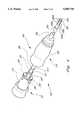
- FIG. 1is a sectional view of the present invention in a fully extended position
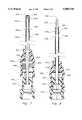
- FIG. 2is a sectional view of the present invention in an intermediate position
- FIG. 3is a sectional view of the present invention in a fully retracted position
- FIG. 4is an isometric view of the present invention.
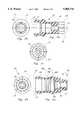
- FIG. 5ais a sectional view of the inner probe shaft housing of the present invention.
- FIG. 5bis a back view of the inner probe shaft housing of the present invention.
- FIG. 5cis a front view of the inner probe shaft housing of the present invention.
- FIG. 6ais a sectional view of the outer probe shaft housing of the present invention.
- FIG. 6bis a back view of the outer probe shaft housing of the present invention.
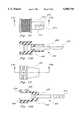
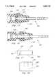
- FIG. 7is a sectional view of the present invention in a fully retracted position for an alternative surgical probe embodiment
- FIG. 8is a sectional view of the present invention in a fully extended position for an alternative surgical probe embodiment
- FIG. 9is a sectional view of the present invention in a fully retracted position for a second alternative surgical probe embodiment
- FIG. 10is a sectional view of the present invention in a fully extended position for a second alternative surgical probe embodiment
- FIG. 11is a perspective view of the preferred embodiment for the telescoping portion of the present invention.
- FIG. 12is a close up perspective view of the invention shown in FIG. 11;
- FIG. 13is a top plan view of the inner base member of the invention shown in FIG. 11;
- FIG. 13Ais a sectional view taken along section line A--A of FIG. 13;
- FIG. 14is a top plan view of the outer base member of the invention shown in FIG. 11;
- FIG. 14Ais a sectional view taken along section line B--B of FIG. 14;
- FIG. 15is a sectional view of the invention shown in FIG. 11;
- FIG. 16is a sectional view of the invention shown in FIG. 11 in an intermediate position
- FIG. 17is a side elevational view of the retainer member of the invention shown in FIG. 12;
- FIG. 18is a side elevational view of the button member of the invention shown in FIG. 12.
- FIGS. 1 through 6illustrates a first embodiment of the present invention.
- the telescopic probeis generally shown at 10 and includes an inner cannula or barrel 12 operatively associated with an outer cannula or barrel 13.
- Probe 10is removeably attached to a (trumpet) valve (not shown) by various conventional methods, including the quick disconnected method which is the subject matter of my application Ser. No. 07/989,109, filed on Dec. 11, 1992.
- the subject matter Ser. No. 07/989,109is hereby incorporated by reference in its entirety into the instant application as if fully set forth herein.
- Inner cannula 12includes an elongated hollow probe shaft or tube 22 having a first end 24 and a second end 26 and defining an internal passageway 27 extending from first end 24 to second end 26.
- groups of holes 28a, 28b, 28c and 28dare disposed along shaft 22 near second end 26.
- First end 24is housed by a first probe shaft housing or base 14.
- housing 14includes a first end 15, a second end 16 and a first shaft receiving cavity 18 for receiving first end 24 of shaft 22.
- Shaft 22is connected to housing 14 by inserting first end 24 into cavity 18 which tightly receives and retains first end 24 therein. Cavity 18 communicates with a valve connecting channel 17.
- probe 10is connected to a valve (not shown) by inserting a probe connection portion of the valve within channel 17.
- a connection methodis the quick disconnect method discussed above.
- Outer cannula 13includes an elongated hollow probe shaft or tube 50 having a first end 52 and a second end 54 and defining an internal passageway 55 extending from first end 52 to second end 54.
- the diameter and length of shaft 50is sized to receive a substantial portion of hollow probe shaft 22 of inner cannula 12, discussed in detail below.
- First end 52is housed by a second probe shaft housing or base 30.
- housing 30contains a second shaft receiving cavity 44 for receiving first end 52 of shaft 50.
- Shaft 50is connected to housing 30 by inserting first end 52 into cavity 44 which tightly receives and retains first end 52 therein.
- Cavity 44communicates with an inner cannula receiving channel 37.
- Disposed between cavity 44 and channel 37can be additional channels 40 and 42.
- Channel 40receives a retainer ring 60, while channel 42 receives a sealing means.
- sealing meansis an o-ring 64.
- Retaining ring 60 and o-ring 64each have associated centerholes 62 and 66 respectively extending therethrough. Centerholes 62 and 66, allow rings 60 and 64, respectively, to be disposed along the outer surface of inner probe shaft 22 when in use.
- inner probe shaft 22is connected to housing 14 and outer probe shaft 50 is connected to housing 30 as previously discussed.
- End 26 of inner probe shaft 22is inserted through channels 37, 40 and 42, and internal passageway 55 of outer probe shaft 50. Once inserted, end 26 of inner probe shaft 22 can be protruding out of second end 54 of outer probe shaft 50 at various lengths, depending on the function desired from the composite probe 10.
- inner probe shaft 22is fully extended out and all of the groups of holes 28a-28d along end 26 of inner shaft 22, as well as aperture 29 at end 26, are utilized in suctioning blood, debris, contaminants and other materials. This inner probe shaft position is particularly used for clearing out pools of blood to enhance the user visibility of the surgical area of the body.
- FIG. 2shows inner probe shaft 22 in an intermediate position between fully extended (FIG. 1) and fully retracted (FIG. 3). In this intermediate position only some of the group of holes 28c and 28d are available for suctioning.
- This inner probe shaft positionis also primarily used for clearing pools of blood disposed at the operative field. However, such pools of blood would have depth levels less than those discussed in the preceding paragraph. Accordingly, only some and not all of the group of holes 28 are needed for sufficient suctioning.
- a plurality of internal grooves 38a, 38b, 38c and 38dare disposed on a portion of the inner surface of channel 37.
- Grooves 38a-38dare used as indicating means and are associated with group of holes 28a-28d, respectively, of inner probe shaft 22 to indicate to the user how many of group of holes 28 are exposed for suctioning purposes. Though four group of holes 28a-28d and four internal grooves 38a-38d are shown, the present invention is not limited to such and any number of holes and corresponding grooves are within the scope of the present invention.
- inner cannula 12Furthermore, if the direction of movement of inner cannula 12 is reversed, each time detent travels over a groove 38, one less number of group of holes 28, than was previously exposed, are available for suctioning. Further reverse traveling by inner cannula causes, accordingly, reduces the number of groups of holes which are exposed until all such groups are disposed within outer probe shaft 50 and unavailable for suctioning (FIG. 3).
- FIG. 3shows inner probe shaft 22 in its fully retracted position. In this position, end 26 of inner probe shaft 22 is completely disposed within the internal passageway 55 defined by outer probe shaft 50. This position is desirable for maximum suction and maximum irrigation. Further, this position can also be used to move around or grab onto various organs at or near the operative field.
- Composite probe 10can be provided with a stoppage means to prevent inner canula 12 from being accidentally or inadvertently removed or dislodged from outer cannula 13.
- the stoppage meansincludes the detent or ridge 20, previously discussed, provided at the inner shaft receiving end 16 of inner shaft housing 14. Detent 20 mates with a corresponding groove 36 disposed within the inner surface of outer shaft housing 30, intermediate internal grooves 38 and first end 32 of outer housing 30.
- detent 20is disposed within and mating with groove 36 to retain inner shaft 22 within outer shaft 50 and prevent accidental or inadvertent removal or dislodging of such.
- sufficient pressure or force exerted by the userwill allow detent 20 to pass over groove 36, thus, allowing the removal of inner probe shaft 22.
- retaining ring 60is shown disposed along inner probe shaft 22 and received within channel 40.
- retaining ring 60is constructed from metal, aluminum, steel, etc.
- Retaining ring 60, along with o-ring 64,provides tension when inner cannula 12 is move in relation to outer cannula 13 as described above.
- o-ring 64acts as a seal and prevents any blood or debris which may travel through outer probe shaft 50 between the inner surface of shaft 50 and the outer surface of shaft 22 from ultimately entering the associated (trumpet) valve.
- outer cannula 13is moved in relation to fixed inner cannula 12 by either rotating, pushing or pulling outer cannula.
- probe 10is not connected to the valve either cannula 12 or 13 can be moved by rotating, pushing or pulling with respect to the other cannula 13 or 12.
- the present inventionallows the user to perform various suctioning functions with a single probe and, thus, without the need to change probes for each various suction function.
- the present inventioncan be incorporated into other probe designs besides the probe illustrated herein, including probes having electrodes and catheters. Thus, these other probe designs incorporating the teachings of the present invention are also within the scope of the invention.
- FIGS. 7 through 10illustrate two different surgical probe embodiments which incorporate the telescoping features of the present invention.
- FIGS. 7 and 8illustrate an alternative surgical probe embodiments from that shown in FIGS. 1 through 6.
- the inner cannula 127consists of elongated portion 150, tapered portion 152 and flat end portion 154, collectively defining an internal passageway 158.
- the first end of inner cannula 127is encompassed by inner housing 114 similar to the probe shown in FIGS. 1 through 6.
- a majority portion of inner cannula 127is flushly disposed or fitted within outer cannula 160.
- Outer cannula 160defines an internal passageway and has a plurality of holes 164 and an opening 162 at its operative end.
- flat end portion 154In its fully retracted position (FIG. 7), flat end portion 154 is seen fully disposed within outer cannula 260, while in its fully extended portion, a substantial portion of flat end portion 154 is seen extending outward through opening 162.
- This embodiment of the present inventionoperates similar to the embodiment shown in FIGS. 1 through 6, to allow inner cannula 127 to be disposed in relation to outer cannula 160 anywhere from a fully retracted to a fully extended position and any point therebetween.
- the locking features and indicators 130also function similar to the embodiment shown in FIGS. 1 through 6.
- FIGS. 9 and 10illustrate a second alternative surgical probe embodiments from that shown in FIGS. 1 through 6.
- the inner cannula 227consists of elongated portion 250, tapered portion 252 and tapered end portion 254, collectively defining an internal passageway 258.
- the first end of inner cannula 227is encompassed by inner housing 214 similar to the probe shown in FIGS. 1 through 6.
- a majority portion of inner cannula 227is flushly disposed or fitted within outer cannula 260.
- Outer cannula 260defines an internal passageway and has a plurality of holes 264 and an opening 262 at its operative end.
- tapered end portion 254In its fully retracted position (FIG. 9), tapered end portion 254 is seen fully disposed within outer cannula 260, while in its fully extended portion, a substantial portion of tapered end portion 254 is seen extending outward through opening 262.
- This embodiment of the present inventionoperates similar to the embodiment shown in FIGS. 1 through 6, to allow inner cannula 227 to be disposed in relation to outer cannula 260 anywhere from a fully retracted to a fully extended position and any point therebetween.
- the locking features and indicators 230also function similar to the embodiment shown in FIGS. 1 through 6.
- the surgical probe embodiment shown in FIGS. 9 and 10is used to penetrate into an acute gall bladder or cyst to aspirate out the bile or contents prior to surgery. This is helpful due to the fact that many times acute gall bladders or cysts will rupture during surgery and spill bile and gall stones or cystic fluid throughout the abdominal cavity. These liquids are difficult to clean up later and are also acidic or dirty, thus, having a negative effect on the patient post-operatively.
- Gynecological laparoscopic cystssuch as chocolate cysts, dermoid cysts and ovarian cysts can also be aspirated in the same manner.
- the sharpened inner cannulawill penetrate into the inner lumen of the cyst or organ and then is retracted back as shown in FIG. 9.
- the outer cannulaacts as a strainer to allow the suction of liquid, but not particulate matter. Irrigation can be squirted inside the lumen to dilute and lower the viscosity of the fluid which makes it easier to suction and cleanse the inner contents of the cyst or organ.
- the inner and outer cannulas of the probeare flush fitted except for the end of the assembly where the inner cannula swages into a smaller diameter. Because of such flush fitting, the probe will aspirate and irrigate through the inner cannula only.
- These probesare used in situations where the physician is aspirating a cyst or some other liquid filled tissue. This is done with the sharpened tapered probe (inner cannula 227 extended out of opening 262), beyond the perforated sheath and aspirating with it as if it were an aspiration or injection needle.
- the usercan use the same probe assembly as a pool sucker to aspirate and other liquid that may have puddled in the area adjacent to the aspiration site.
- FIGS. 11 through 18illustrate the preferred embodiment for the telescoping means 300 of the present invention.
- telescoping meansallows an inner cannula 302 to be disposed at various positions in relation to an outer cannula 304.
- an inner probe shaft 306is connected to an inner base housing 308 and an outer probe shaft 350 is connected to an outer base housing 352.
- Outer base 352defines a receiving channel 360 for receiving a portion 310 of inner base 308.
- End 310 of inner probe shaft 306is inserted through an internal passageway of outer probe shaft 304. Once inserted, end 310 of inner probe shaft 306 can be protruding out of a second end 354 of outer probe shaft 350 at various lengths, depending on the function desired, similar to composite probe 10 of FIGS. 1 through 3.
- a button receiving cavity 356communicates with a channel 358 to create a passageway through outer base 352.
- a portion of a button 380is disposed within cavity 356.
- Button 380defines a retainer attachment cavity 382 which is in communication with a spring receiving cavity 384, also defined by button 380.
- a first end 392 of a retaining pin 390is inserted within cavity 382 and attached to button 380 by conventional means such as gluing.
- Pin 390has an outer lip 394 disposed at its second end 396. Lip 394 is larger in diameter than the remaining area of pin 390 and is also larger in diameter than the diameter of channel 358. Ends 392 and 396 define therebetween a middle pin area 398 having a predetermined length.
- a portion of a spring 400is disposed within cavity 356 and the remaining portion of spring 400 extends outward from outer base 352.
- Pin end 392is inserted through channel 358 and cavity 356, as well as spring 400, and ready for attachment to button 380.
- a portion of button 380is disposed within cavity 356, such that the portion of spring 400 extending out from outer base 352, is received within button cavity 384 and pin end 392, which is received within cavity 382 and subsequently attached to button 380, preferably by gluing.
- spring 400is bordered at one end by the bottom surface of cavity 356 and at its opposite end by the bottom surface of button cavity 384 and is disposed around a portion of middle area 398 of retaining pin 390.
- portion 310 of inner base 308has a slot 312 extending along a substantial portion of the length of portion 310.
- Cylindrical openings 314are disposed at predetermined locations along slot 312, for receiving lip 394 and a small portion of middle area 398, adjacent lip 394, during use of telescoping means 300. Openings 314 are chosen cylindrical to correspond with the cylindrical shape of lip 394. However, it is to be understood that other shapes can be utilized for openings 314 and lip 394 and are within the scope of the present invention.
- the distance spanning across slot 312is slightly smaller between the length of slot 312 bounded by the last opening 314 and end 311 of portion 310 and the remaining length of slot 312. This feature helps to prevent inadvertent or accidental detachment of the outer probe from the inner probe during use of the composite probe.
- inner probe shaft 306is inserted through outer base 352 and within outer probe shaft 350 until end 311 of portion 310 is abutting lip 394 and slot 312 is aligned with lip 394.
- button 380is in an upright position as spring 400 is fully extended.
- the diameter of lip 394is larger than distance across slot 312, thus preventing lip 394 from entering slot 312, even when force is applied.
- the pressing of button 380also causing spring 400 to compress, allows a portion of middle area 398 to be aligned with slot 312. This area is smaller in diameter than lip 394 and upon a little force by the user, allows retainer 390 to enter slot 312.
- button 380will pop up and return to its upright position.
- Spring 400is designed to fully extend to a point where lip 394 of retainer 390 is disposed within and aligned with opening 314, as the diameter of opening 314 is slightly larger than the diameter of lip 394. However, as the diameter of lip 394 is larger than the distance across slot 312, retainer 390 is prevented from further horizontal movement along slot 312, even when force is applied.
- the inner probe shaftis locked in position with respect to the outer probe shaft, as well as retainer 390 being locked with respect to its ability to move horizontally along slot 312.
- the pressing of button 380again allows a portion of middle area 398 to be aligned with slot 312, thus allowing retainer 390 to enter slot 312, in the direction of the force that is being applied.
- openings 314are shown having three openings 314, such number is not limiting and any number of openings 314 is within the scope of the invention and may be provided depending characteristics and features of the inner and outer probes of the composite probe. Like grooves 38a-38d of FIGS. 1 through 3, openings 314 may also correspond to certain holes or apertures, as well as other features, disposed at end 310 of inner probe shaft 306.
Landscapes
- Health & Medical Sciences (AREA)
- Life Sciences & Earth Sciences (AREA)
- Heart & Thoracic Surgery (AREA)
- Engineering & Computer Science (AREA)
- Anesthesiology (AREA)
- Biomedical Technology (AREA)
- Hematology (AREA)
- Animal Behavior & Ethology (AREA)
- General Health & Medical Sciences (AREA)
- Public Health (AREA)
- Veterinary Medicine (AREA)
- Biophysics (AREA)
- Pulmonology (AREA)
- Vascular Medicine (AREA)
- Surgery (AREA)
- Endoscopes (AREA)
Abstract
Description
1. Field of the Invention
The present invention relates generally to endoscopic/laparoscopic instruments, and more particularly, to a telescoping surgical probe.
2. Description of the Prior Art
Hydrodissection procedures typically involve directing a pressurized fluid stream at a target tissue through a probe, followed thereafter by suction of the fluid from the operative field through the same probe; or, through a probe connected to a separate instrument. This procedure, as practiced with a symmetrical valve of the type disclosed in U.S. Pat. No. 5,188,591, simply involves the sequential depression of the irrigation piston connected to the source of the hydrodissection fluid, release of the irrigation piston, which discontinues the flow of fluid, depression of the suction piston to effect aspiration of fluid from the operative field, and the repetition of the above sequence.
In the past various probes have been utilized for various suction and irrigation situations that arise during the operative procedure. Such situations include the clearing of different depth levels of blood located at the operative field, suctioning of tissue and other debris, or the use of suction and irrigation to move or dissect various organs or adhesions at or near the operative field. Thus, each time a different need arisen for suction or irrigation which could not be accomplished by the probe attached to the valve, such probe had to be removed from the valve and replaced with the appropriate probe. Accordingly, valuable surgical time is wasted by the replacement of one probe for another.
What is needed in the art is a single surgical probe which contains the various suction tips and their companion uses and features described above, as well as irrigation oriented probe tips, thus, allowing the user to perform various tasks with suction or irrigation with the use of a single probe. It is, therefore, to the effective resolution of the aforementioned problems and shortcomings that the present invention is directed.
The present invention provides a telescoping surgical probe which allows an inner cannula to be positioned in relationship to an outer cannula from a closed position to an open position and any position therebetween. The inner cannula contains a hollow probe shaft connected to a probe shaft housing. The outer cannula also contains a hollow probe shaft and a probe shaft housing. The diameter of the outer probe shaft is larger than the diameter of the inner probe to allow the inner probe shaft to be inserted within the outer probe shaft. In one configuration, a plurality of apertures are disposed near one end of the inner probe shaft.
In the invention first embodiment, how far the inner probe shaft has been inserted within the outer probe shaft, will determine how many of the plurality of apertures extend out the non-inserted end of outer probe shaft, if any at all. In one embodiment, a spring actuated button having a retainer member attached thereto is disposed at the base of the outer probe shaft. A portion of the retainer member extends within a slot disposed on a portion of the base of the inner probe to guide and lock the inner probe shaft with respect to the outer probe shaft.
In another embodiment, a plurality of grooves can be provided on the inner surface of the outer probe shaft housing which, in conjunction with a detent or chamfer disposed on the inner shaft housing, aid the user in exposing only the amount of apertures required for the desired function of the probe. The detent, in conjunction with another groove disposed on the inner surface of the probe shaft housing, also helps prevent the inner probe shaft from becoming accidentally removed or dislodged from the outer probe shaft.
Accordingly, the present invention provides a single probe which can convert to a probe tip with holes or to a probe tip without holes.
It is therefore an object of the present invention to provide a surgical probe which can perform various suction functions.
It is another object of the present invention to save surgical time during hydrodissection procedures.
It is still another object of the present invention to eliminate the need to switch surgical probes for various suction situations.
In accordance with these and other objects which will become apparent hereinafter, the instant invention will now be described with particular reference to the accompanying drawings.
The invention may be better understood by reference to the drawings in which:
FIG. 1 is a sectional view of the present invention in a fully extended position;
FIG. 2 is a sectional view of the present invention in an intermediate position;
FIG. 3 is a sectional view of the present invention in a fully retracted position;
FIG. 4 is an isometric view of the present invention;
FIG. 5a is a sectional view of the inner probe shaft housing of the present invention;
FIG. 5b is a back view of the inner probe shaft housing of the present invention;
FIG. 5c is a front view of the inner probe shaft housing of the present invention;
FIG. 6a is a sectional view of the outer probe shaft housing of the present invention;
FIG. 6b is a back view of the outer probe shaft housing of the present invention;
FIG. 7 is a sectional view of the present invention in a fully retracted position for an alternative surgical probe embodiment;
FIG. 8 is a sectional view of the present invention in a fully extended position for an alternative surgical probe embodiment;
FIG. 9 is a sectional view of the present invention in a fully retracted position for a second alternative surgical probe embodiment;
FIG. 10 is a sectional view of the present invention in a fully extended position for a second alternative surgical probe embodiment;
FIG. 11 is a perspective view of the preferred embodiment for the telescoping portion of the present invention;
FIG. 12 is a close up perspective view of the invention shown in FIG. 11;
FIG. 13 is a top plan view of the inner base member of the invention shown in FIG. 11;
FIG. 13A is a sectional view taken along section line A--A of FIG. 13;
FIG. 14 is a top plan view of the outer base member of the invention shown in FIG. 11;
FIG. 14A is a sectional view taken along section line B--B of FIG. 14;
FIG. 15 is a sectional view of the invention shown in FIG. 11;
FIG. 16 is a sectional view of the invention shown in FIG. 11 in an intermediate position;
FIG. 17 is a side elevational view of the retainer member of the invention shown in FIG. 12; and
FIG. 18 is a side elevational view of the button member of the invention shown in FIG. 12.
FIGS. 1 through 6 illustrates a first embodiment of the present invention. The telescopic probe is generally shown at 10 and includes an inner cannula orbarrel 12 operatively associated with an outer cannula orbarrel 13.Probe 10 is removeably attached to a (trumpet) valve (not shown) by various conventional methods, including the quick disconnected method which is the subject matter of my application Ser. No. 07/989,109, filed on Dec. 11, 1992. The subject matter Ser. No. 07/989,109 is hereby incorporated by reference in its entirety into the instant application as if fully set forth herein.
Retainingring 60 and o-ring 64 each have associated centerholes 62 and 66 respectively extending therethrough. Centerholes 62 and 66, allowrings inner probe shaft 22 when in use.
As seen in FIGS. 1 through 3, the present invention allowsinner cannula 12 to be disposed at various positions in relation toouter cannula 13. In operation,inner probe shaft 22 is connected tohousing 14 andouter probe shaft 50 is connected tohousing 30 as previously discussed.End 26 ofinner probe shaft 22 is inserted throughchannels internal passageway 55 ofouter probe shaft 50. Once inserted, end 26 ofinner probe shaft 22 can be protruding out ofsecond end 54 ofouter probe shaft 50 at various lengths, depending on the function desired from thecomposite probe 10. Thus, in FIG. 1inner probe shaft 22 is fully extended out and all of the groups ofholes 28a-28d alongend 26 ofinner shaft 22, as well asaperture 29 atend 26, are utilized in suctioning blood, debris, contaminants and other materials. This inner probe shaft position is particularly used for clearing out pools of blood to enhance the user visibility of the surgical area of the body.
FIG. 2 showsinner probe shaft 22 in an intermediate position between fully extended (FIG. 1) and fully retracted (FIG. 3). In this intermediate position only some of the group ofholes
In one embodiment of the telescoping means of the present invention, a plurality ofinternal grooves channel 37.Grooves 38a-38d are used as indicating means and are associated with group ofholes 28a-28d, respectively, ofinner probe shaft 22 to indicate to the user how many of group of holes 28 are exposed for suctioning purposes. Though four group ofholes 28a-28d and fourinternal grooves 38a-38d are shown, the present invention is not limited to such and any number of holes and corresponding grooves are within the scope of the present invention.
Thus, in operation and in the fully retracted position (FIG. 3), the movement ofinner cannula 12 forward causes detent 20 to travel overgroove 38a and provides a click. At this point,only hole 28a will be exposed from out ofouter probe shaft 50 for suctioning. Further forward movement ofinner cannula 12 causes detent 20 to travel over groove 38b. At this point groups ofholes 28a and 28b are exposed from out ofouter probe shaft 50. Thus, the number of grooves 38 that detent 20 travels over during the forward movement ofinner cannula 12 will indicate to the user how many groups of holes are exposed for suctioning. Oncedetent 20 has traveled over all of internal grooves 38, all of the groups of holes 28 are exposed and able to be used for suctioning.
Furthermore, if the direction of movement ofinner cannula 12 is reversed, each time detent travels over a groove 38, one less number of group of holes 28, than was previously exposed, are available for suctioning. Further reverse traveling by inner cannula causes, accordingly, reduces the number of groups of holes which are exposed until all such groups are disposed withinouter probe shaft 50 and unavailable for suctioning (FIG. 3).
As mentioned in the previous paragraph, FIG. 3 showsinner probe shaft 22 in its fully retracted position. In this position, end 26 ofinner probe shaft 22 is completely disposed within theinternal passageway 55 defined byouter probe shaft 50. This position is desirable for maximum suction and maximum irrigation. Further, this position can also be used to move around or grab onto various organs at or near the operative field.Composite probe 10 can be provided with a stoppage means to preventinner canula 12 from being accidentally or inadvertently removed or dislodged fromouter cannula 13. Preferably, the stoppage means includes the detent orridge 20, previously discussed, provided at the innershaft receiving end 16 ofinner shaft housing 14.Detent 20 mates with a correspondinggroove 36 disposed within the inner surface ofouter shaft housing 30, intermediate internal grooves 38 andfirst end 32 ofouter housing 30.
As seen in FIG. 3, wheninner shaft 22 is fully retracted within outer probe shaft,detent 20 is disposed within and mating withgroove 36 to retaininner shaft 22 withinouter shaft 50 and prevent accidental or inadvertent removal or dislodging of such. However, when it is desired to removeinner shaft 22 fromouter shaft 50, sufficient pressure or force exerted by the user will allowdetent 20 to pass overgroove 36, thus, allowing the removal ofinner probe shaft 22.
As seen in FIGS. 1-3retaining ring 60 is shown disposed alonginner probe shaft 22 and received withinchannel 40. Preferably, retainingring 60 is constructed from metal, aluminum, steel, etc. Retainingring 60, along with o-ring 64, provides tension wheninner cannula 12 is move in relation toouter cannula 13 as described above. Furthermore, o-ring 64 acts as a seal and prevents any blood or debris which may travel throughouter probe shaft 50 between the inner surface ofshaft 50 and the outer surface ofshaft 22 from ultimately entering the associated (trumpet) valve.
When it is desirable to change the position of thecannula 12 with respect tocannula 13 andprobe 10 is connected to a valve,outer cannula 13 is moved in relation to fixedinner cannula 12 by either rotating, pushing or pulling outer cannula. However, ifprobe 10 is not connected to the valve eithercannula other cannula
Thus the present invention allows the user to perform various suctioning functions with a single probe and, thus, without the need to change probes for each various suction function. The present invention can be incorporated into other probe designs besides the probe illustrated herein, including probes having electrodes and catheters. Thus, these other probe designs incorporating the teachings of the present invention are also within the scope of the invention.
For example, FIGS. 7 through 10 illustrate two different surgical probe embodiments which incorporate the telescoping features of the present invention. FIGS. 7 and 8 illustrate an alternative surgical probe embodiments from that shown in FIGS. 1 through 6. In this embodiment theinner cannula 127 consists ofelongated portion 150, taperedportion 152 andflat end portion 154, collectively defining aninternal passageway 158. The first end ofinner cannula 127 is encompassed byinner housing 114 similar to the probe shown in FIGS. 1 through 6. A majority portion ofinner cannula 127 is flushly disposed or fitted withinouter cannula 160.Outer cannula 160 defines an internal passageway and has a plurality ofholes 164 and anopening 162 at its operative end.
In its fully retracted position (FIG. 7),flat end portion 154 is seen fully disposed withinouter cannula 260, while in its fully extended portion, a substantial portion offlat end portion 154 is seen extending outward throughopening 162. This embodiment of the present invention, operates similar to the embodiment shown in FIGS. 1 through 6, to allowinner cannula 127 to be disposed in relation toouter cannula 160 anywhere from a fully retracted to a fully extended position and any point therebetween. Furthermore, the locking features andindicators 130 also function similar to the embodiment shown in FIGS. 1 through 6.
FIGS. 9 and 10 illustrate a second alternative surgical probe embodiments from that shown in FIGS. 1 through 6. In this embodiment theinner cannula 227 consists ofelongated portion 250, taperedportion 252 andtapered end portion 254, collectively defining aninternal passageway 258. The first end ofinner cannula 227 is encompassed byinner housing 214 similar to the probe shown in FIGS. 1 through 6. A majority portion ofinner cannula 227 is flushly disposed or fitted withinouter cannula 260.Outer cannula 260 defines an internal passageway and has a plurality ofholes 264 and anopening 262 at its operative end.
In its fully retracted position (FIG. 9), taperedend portion 254 is seen fully disposed withinouter cannula 260, while in its fully extended portion, a substantial portion oftapered end portion 254 is seen extending outward throughopening 262. This embodiment of the present invention, operates similar to the embodiment shown in FIGS. 1 through 6, to allowinner cannula 227 to be disposed in relation toouter cannula 260 anywhere from a fully retracted to a fully extended position and any point therebetween. Furthermore, the locking features andindicators 230 also function similar to the embodiment shown in FIGS. 1 through 6.
The surgical probe embodiment shown in FIGS. 9 and 10 is used to penetrate into an acute gall bladder or cyst to aspirate out the bile or contents prior to surgery. This is helpful due to the fact that many times acute gall bladders or cysts will rupture during surgery and spill bile and gall stones or cystic fluid throughout the abdominal cavity. These liquids are difficult to clean up later and are also acidic or dirty, thus, having a negative effect on the patient post-operatively. Gynecological laparoscopic cysts, such as chocolate cysts, dermoid cysts and ovarian cysts can also be aspirated in the same manner. The sharpened inner cannula will penetrate into the inner lumen of the cyst or organ and then is retracted back as shown in FIG. 9. The outer cannula acts as a strainer to allow the suction of liquid, but not particulate matter. Irrigation can be squirted inside the lumen to dilute and lower the viscosity of the fluid which makes it easier to suction and cleanse the inner contents of the cyst or organ.
In these alternative surgical probe embodiments (FIGS. 7 through 10), the inner and outer cannulas of the probe are flush fitted except for the end of the assembly where the inner cannula swages into a smaller diameter. Because of such flush fitting, the probe will aspirate and irrigate through the inner cannula only. These probes are used in situations where the physician is aspirating a cyst or some other liquid filled tissue. This is done with the sharpened tapered probe (inner cannula 227 extended out of opening 262), beyond the perforated sheath and aspirating with it as if it were an aspiration or injection needle. By advancing the outer probe and covering the needle, the user can use the same probe assembly as a pool sucker to aspirate and other liquid that may have puddled in the area adjacent to the aspiration site.
FIGS. 11 through 18 illustrate the preferred embodiment for the telescoping means 300 of the present invention. Like FIGS. 1 through 3, telescoping means allows aninner cannula 302 to be disposed at various positions in relation to anouter cannula 304. In operation, aninner probe shaft 306 is connected to aninner base housing 308 and anouter probe shaft 350 is connected to anouter base housing 352.Outer base 352 defines a receivingchannel 360 for receiving aportion 310 ofinner base 308.End 310 ofinner probe shaft 306 is inserted through an internal passageway ofouter probe shaft 304. Once inserted, end 310 ofinner probe shaft 306 can be protruding out of asecond end 354 ofouter probe shaft 350 at various lengths, depending on the function desired, similar tocomposite probe 10 of FIGS. 1 through 3.
Abutton receiving cavity 356 communicates with achannel 358 to create a passageway throughouter base 352. A portion of abutton 380 is disposed withincavity 356.Button 380 defines aretainer attachment cavity 382 which is in communication with aspring receiving cavity 384, also defined bybutton 380. Afirst end 392 of a retainingpin 390 is inserted withincavity 382 and attached tobutton 380 by conventional means such as gluing.Pin 390 has anouter lip 394 disposed at itssecond end 396.Lip 394 is larger in diameter than the remaining area ofpin 390 and is also larger in diameter than the diameter ofchannel 358.Ends middle pin area 398 having a predetermined length.
Before attachingend 392 tobutton 380, a portion of aspring 400 is disposed withincavity 356 and the remaining portion ofspring 400 extends outward fromouter base 352.Pin end 392 is inserted throughchannel 358 andcavity 356, as well asspring 400, and ready for attachment tobutton 380. A portion ofbutton 380 is disposed withincavity 356, such that the portion ofspring 400 extending out fromouter base 352, is received withinbutton cavity 384 andpin end 392, which is received withincavity 382 and subsequently attached tobutton 380, preferably by gluing. In use,spring 400 is bordered at one end by the bottom surface ofcavity 356 and at its opposite end by the bottom surface ofbutton cavity 384 and is disposed around a portion ofmiddle area 398 of retainingpin 390.
As seen in FIGS. 13 and 13A,portion 310 ofinner base 308 has aslot 312 extending along a substantial portion of the length ofportion 310.Cylindrical openings 314 are disposed at predetermined locations alongslot 312, for receivinglip 394 and a small portion ofmiddle area 398,adjacent lip 394, during use of telescoping means 300.Openings 314 are chosen cylindrical to correspond with the cylindrical shape oflip 394. However, it is to be understood that other shapes can be utilized foropenings 314 andlip 394 and are within the scope of the present invention. The distance spanning acrossslot 312 is slightly smaller between the length ofslot 312 bounded by thelast opening 314 and end 311 ofportion 310 and the remaining length ofslot 312. This feature helps to prevent inadvertent or accidental detachment of the outer probe from the inner probe during use of the composite probe.
In use,inner probe shaft 306 is inserted throughouter base 352 and withinouter probe shaft 350 untilend 311 ofportion 310 is abuttinglip 394 andslot 312 is aligned withlip 394. At this point,button 380 is in an upright position asspring 400 is fully extended. The diameter oflip 394 is larger than distance acrossslot 312, thus preventinglip 394 from enteringslot 312, even when force is applied. However, the pressing ofbutton 380 also causingspring 400 to compress, allows a portion ofmiddle area 398 to be aligned withslot 312. This area is smaller in diameter thanlip 394 and upon a little force by the user, allowsretainer 390 to enterslot 312.
Ifretainer 390 is disposed within any ofopenings 314, onebutton 380 is no longer pressed,button 380 will pop up and return to its upright position.Spring 400 is designed to fully extend to a point wherelip 394 ofretainer 390 is disposed within and aligned withopening 314, as the diameter ofopening 314 is slightly larger than the diameter oflip 394. However, as the diameter oflip 394 is larger than the distance acrossslot 312,retainer 390 is prevented from further horizontal movement alongslot 312, even when force is applied. Thus, the inner probe shaft is locked in position with respect to the outer probe shaft, as well asretainer 390 being locked with respect to its ability to move horizontally alongslot 312. However, the pressing ofbutton 380 again allows a portion ofmiddle area 398 to be aligned withslot 312, thus allowingretainer 390 to enterslot 312, in the direction of the force that is being applied.
If the button is no longer pressed while retainer is disposed withinslot 312,slot 312 being smaller than the diameter oflip 394, will preventretainer 390 andspring 400 from moving in a vertical direction andlip 394 will remain disposed underslot 312. In this position, the inner and outer probe shafts andretainer 390 are not locked in position and by applying force,retainer 390 will move horizontally alongslot 312 in the direction of the force until it reaches one of theopenings 314. Onceretainer 390 reaches anopening 314, it becomes locked in position as described above, thus, also causingspring 400 to fully extend andbutton 380 to pop up to its upright position.
Theslot 312 is shown having threeopenings 314, such number is not limiting and any number ofopenings 314 is within the scope of the invention and may be provided depending characteristics and features of the inner and outer probes of the composite probe. Likegrooves 38a-38d of FIGS. 1 through 3,openings 314 may also correspond to certain holes or apertures, as well as other features, disposed atend 310 ofinner probe shaft 306.
The instant invention has been shown and described herein in what is considered to be the most practical and preferred embodiment. It is recognized, however, that departures may be made therefrom within the scope of the invention and that obvious modifications will occur to a person skilled in the art.
Claims (24)
1. A surgical probe for use with a valve, comprising:
an inner cannula having a first end and a second end and being operatively associated with said valve, said inner cannula also having an internal passageway extending therethrough from the first end to the second end; and
an outer cannula having a first end and a second end and being operatively associated with said inner cannula, said outer cannula also having an internal passageway extending therethrough from the first end to the second end of said outer cannula, at least a portion of said inner cannula disposed within the internal passageway of said outer cannula;
wherein either said inner cannula or said outer cannula is moved in relation with the other cannula to allow said probe to perform various suction and irrigation functions associated with laparascopic and endoscopic surgery.
2. A surgical probe for use with a valve, comprising:
an inner cannula having an inner probe shaft and an inner shaft housing, said inner probe shaft having a first end and a second end, said inner shaft housing having a first end and a second end, the first end of said inner probe shaft connected to the second end of said inner shaft housing, said first end of said inner shaft housing operatively associated with the valve; and
an outer cannula having an outer probe shaft and an outer shaft housing, said outer probe shaft having a first end and a second end, said outer shaft housing having a first end and a second end, the first end of said outer probe shaft connected to the second end of said outer shaft housing, at least a portion of said inner cannula disposed within said outer cannula;
wherein either said inner cannula or said outer cannula is moved in relation with the other cannula to allow said probe to perform various suction and irrigation functions associated with laparascopic and endoscopic surgery.
3. The surgical probe of claim 2 wherein said inner probe shaft defining a first internal passageway extending from the first end to the second end of said inner probe shaft, said inner shaft housing defining a first internal channel extending from the first end to the second end of said inner shaft housing, said first internal passageway communicating with said first internal channel when said inner probe shaft is connected to said inner shaft housing, said outer probe shaft defining a second internal passageway extending from the first end to the second end of said outer probe shaft, said outer shaft housing defining a second internal channel extending from the first end to the second end of said outer shaft housing, said second internal passageway communicating with said second internal channel when said outer probe shaft is connected to said outer shaft housing.
4. The surgical probe of claim 3 wherein said second internal passageway is sized larger in diameter than said inner probe shaft's diameter and said second internal channel is sized larger in diameter than the second end of said inner shaft housing's diameter.
5. The surgical probe of claim 2 further including means for retaining at least a portion of said inner probe shaft within said outer probe shaft.
6. The surgical probe of claim 5 wherein said means for retaining comprises a detent disposed at the second end of said inner shaft housing and a correspondingly shaped groove disposed within an inner surface of said outer shaft housing.
7. The surgical probe of claim 2 wherein said inner probe shaft having an inner surface and an outer surface and said outer probe shaft having an inner surface and an outer surface, said surgical probe further including means for sealing a space created between said inner surface of said outer probe shaft and said outer surface of said inner probe shaft when said inner probe shaft is received within said outer probe shaft.
8. The surgical probe of claim 7 wherein said means for sealing is an o-ring disposed along the outer surface of said inner probe shaft or disposed within said outer shaft housing.
9. The surgical probe of claim 2 further including means for providing a tension fit between said inner probe shaft and said outer probe shaft when said inner probe shaft is received within said outer probe shaft.
10. The surgical probe of claim 9 wherein said means for providing is a retaining ring disposed along an outer surface portion of said inner probe shaft or disposed within said outer shaft housing.
11. The surgical probe of claim 2, further including means for determining the position of said inner probe shaft with respect to said outer probe shaft.
12. The surgical probe of claim 11 wherein said means for determining includes at least one groove disposed within an inner surface of said outer shaft housing and a detent disposed at the second end of said inner shaft housing.
13. The surgical probe of claim 12 wherein each said groove corresponds to a specific position of said inner probe shaft with respect to said outer probe shaft.
14. The surgical probe of claim 2, further including means for positioning said inner probe shaft with respect to said outer probe shaft.
15. The surgical probe of claim 14 wherein said means for positioning comprises an elongated slot disposed along a portion of said inner shaft housing and a spring-actuated locking means, a portion of said locking means disposed within said slot.
16. The surgical probe of claim 15 wherein said locking means comprises a button member, spring means and retainer member, a first end of said retainer member inserted through said spring means and attached to said button member, a second end of said retainer member being disposed within said slot, wherein by depressing said button member, said retainer member may be moved along said slot to position or move said inner probe shaft with respect to said outer probe shaft.
17. The surgical probe of claim 15, further including means for determining the position of said inner probe shaft with respect to said outer probe shaft.
18. The surgical probe of claim 17 wherein said means for determining includes at least one aperture disposed along said slot.
19. The surgical probe of claim 18 wherein each said aperture disposed along said slot corresponds to a specific position of said inner probe shaft with respect to said outer probe shaft.
20. A surgical probe for use with a valve, comprising:
an inner cannula having an inner probe shaft defining a first internal passageway extending from a first end to a second end of said inner probe shaft and an inner shaft housing defining a first internal channel extending from a first end to a second end of said inner shaft housing, the first end of said inner probe shaft connected to the second end of said inner shaft housing to allow communication between said first internal passageway and said first internal channel, the first end of said inner shaft housing operatively associated with the valve;
an elongated slot extending along a portion of said inner shaft housing;
an outer cannula having an outer probe shaft defining a second internal passageway extending from a first end to a second end of said outer probe shaft and an outer shaft housing defining a second internal channel extending from a first end to a second end of said outer shaft housing, the first end of said outer probe shaft connected to the second end of said outer shaft housing to allow communication between said second internal passageway and said second internal channel, at least a portion of said inner probe shaft disposed within said second internal channel and said second internal passageway, at least a portion of the second end of said inner shaft housing disposed within said second internal channel;
a spring-actuated locking means operatively associated with said outer shaft housing, a portion of said locking means disposed within said slot;
an o-ring disposed along an outer surface portion of said inner probe shaft, said o-ring providing a blockage seal for material and debris entering the space created between said inner probe shaft and said outer probe shaft when said inner probe shaft is inserted within the second internal passageway of said outer probe shaft; and
a retaining ring disposed along an outer surface portion of said inner probe shaft intermediated said o-ring and the first end of said inner probe shaft, said retaining ring providing a tension fit between said inner probe shaft and said outer probe shaft when said inner probe shaft is received within said outer probe shaft;
wherein either said inner cannula or said outer cannula is moved in relation with the other cannula to perform various functions.
21. The surgical probe of claim 20 wherein said locking means comprises a button member, spring means and retainer member, a first end of said retainer member inserted through said spring means and attached to said button member, a second end of said retainer member being disposed within said slot, wherein by depressing said button member, said retainer member may be moved along said slot to position or move said inner probe shaft with respect to said outer probe shaft.
22. The surgical probe of claim 21, further including means for determining the position of said inner probe shaft with respect to said outer probe shaft.
23. The surgical probe of claim 22 wherein said means for determining includes at least one aperture disposed along said slot.
24. The surgical probe of claim 23 wherein each said aperture disposed along said slot corresponding to a specific position of said inner probe shaft with respect to said outer probe shaft.
Priority Applications (1)
| Application Number | Priority Date | Filing Date | Title |
|---|---|---|---|
| US08/293,715US5505710A (en) | 1994-08-22 | 1994-08-22 | Telescoping probe |
Applications Claiming Priority (1)
| Application Number | Priority Date | Filing Date | Title |
|---|---|---|---|
| US08/293,715US5505710A (en) | 1994-08-22 | 1994-08-22 | Telescoping probe |
Publications (1)
| Publication Number | Publication Date |
|---|---|
| US5505710Atrue US5505710A (en) | 1996-04-09 |
Family
ID=23130250
Family Applications (1)
| Application Number | Title | Priority Date | Filing Date |
|---|---|---|---|
| US08/293,715Expired - LifetimeUS5505710A (en) | 1994-08-22 | 1994-08-22 | Telescoping probe |
Country Status (1)
| Country | Link |
|---|---|
| US (1) | US5505710A (en) |
Cited By (133)
| Publication number | Priority date | Publication date | Assignee | Title |
|---|---|---|---|---|
| WO1997014457A1 (en)* | 1995-10-18 | 1997-04-24 | Stouder Albert E Jr | Adjustable length cannula and trocar |
| US5882344A (en)* | 1995-10-18 | 1999-03-16 | Stouder, Jr.; Albert E. | Adjustable length cannula and trocar |
| WO1999038560A1 (en)* | 1998-02-03 | 1999-08-05 | Salient Interventional Systems, Inc. | Methods and systems for treating ischemia |
| DE29920949U1 (en) | 1999-11-29 | 2000-04-27 | Bugge, Mogens, Göteborg | Suction tube for surgical purposes |
| US6096022A (en)* | 1995-08-31 | 2000-08-01 | Target Therapeutics Inc. | Bi-directional catheter |
| US6254061B1 (en) | 1999-04-30 | 2001-07-03 | Scimed Life Systems, Inc. | Medical suction valve |
| US6295990B1 (en) | 1998-02-03 | 2001-10-02 | Salient Interventional Systems, Inc. | Methods and systems for treating ischemia |
| US20020091362A1 (en)* | 1998-01-06 | 2002-07-11 | Maginot Thomas J. | Medical procedure using catheter system having removability feature |
| WO2002049537A3 (en)* | 2000-12-19 | 2002-08-22 | Orqis Medical Corp | Improved percutaneous catheter assembly |
| WO2003066148A1 (en)* | 2002-02-07 | 2003-08-14 | C.R. Bard, Inc. | Split tip dialysis catheter |
| WO2003070309A1 (en)* | 2002-02-19 | 2003-08-28 | Antea Associazione | Improvement of intra-venous (i.v.) blood catheter for subcutaneous infusion of liquids and/or drugs |
| US6622367B1 (en) | 1998-02-03 | 2003-09-23 | Salient Interventional Systems, Inc. | Intravascular device and method of manufacture and use |
| US20040064058A1 (en)* | 2001-10-24 | 2004-04-01 | Mckay William F. | Methods and instruments for treating pseudoarthrosis |
| US6723084B1 (en)* | 1999-01-15 | 2004-04-20 | Maginot Catheter Technologies, Inc. | Catheter systems having multilumen guide catheter and retractable working catheter positioned in at least one lumen thereof |
| US6728565B2 (en)* | 2000-02-25 | 2004-04-27 | Scimed Life Systems, Inc. | Diagnostic catheter using a vacuum for tissue positioning |
| US20040116768A1 (en)* | 1997-10-09 | 2004-06-17 | Bolling Steven F. | Implantable heart assist system and method of applying same |
| FR2854788A1 (en)* | 2003-05-13 | 2004-11-19 | Edgard Cornier | Device for placing uterine suspension prosthesis comprises tubular trocar with lateral connector at proximal end connected to drip parts and at distal end perforations for evacuation of drip liquid, mandrel introduced in trocar has eye |
| US20040236173A1 (en)* | 2002-02-15 | 2004-11-25 | Anthony Viole | Implantable heart assist system and method of applying same |
| US20050059925A1 (en)* | 1999-01-15 | 2005-03-17 | Maginot Thomas J. | Catheter systems and associated methods |
| US20050085683A1 (en)* | 2003-10-15 | 2005-04-21 | Bolling Steven F. | Implantable heart assist system and method of applying same |
| US20050096609A1 (en)* | 1999-01-15 | 2005-05-05 | Maginot Thomas J. | Methods of performing medical procedures with catheter systems having movable member |
| US20050113825A1 (en)* | 1996-09-20 | 2005-05-26 | Ioan Cosmescu | Multifunctional telescopic monopolar/bipolar surgical device and method therefore |
| US20050131385A1 (en)* | 2003-12-12 | 2005-06-16 | Bolling Steven F. | Cannulae for selectively enhancing blood flow |
| US20050159711A1 (en)* | 2004-01-20 | 2005-07-21 | Kathrani Biten K. | Medical device for providing access |
| US20050256525A1 (en)* | 2002-11-14 | 2005-11-17 | Brad Culbert | Dilation introducer for orthopedic surgery |
| US20050277803A1 (en)* | 2004-06-10 | 2005-12-15 | Robert Pecor | Cannulae having reduced flow resistance |
| US20050277870A1 (en)* | 2004-06-10 | 2005-12-15 | Robert Pecor | Cannula having reduced flow resistance |
| EP1333774A4 (en)* | 2000-09-26 | 2005-12-28 | Ethicon Inc | Surgical apparatus and methods for delivery of a sling in the treatment of female urinary incontinence |
| US20060004325A1 (en)* | 2004-07-02 | 2006-01-05 | Bret Hamatake | Tip configurations for a multi-lumen catheter |
| US20060030872A1 (en)* | 2004-08-03 | 2006-02-09 | Brad Culbert | Dilation introducer for orthopedic surgery |
| FR2874330A1 (en)* | 2004-08-20 | 2006-02-24 | Edgard Cornier | DEVICE FOR ESTABLISHING UTERINE SUSPENSION PROSTHESIS FOR THE TREATMENT OF UTERINE PROLAPSUS |
| US20060047253A1 (en)* | 2004-08-24 | 2006-03-02 | Hayman Michael H | Needle assembly |
| US20060087334A1 (en)* | 2004-10-21 | 2006-04-27 | James Annichiarico | Dual tip probe |
| US20060184199A1 (en)* | 2005-02-14 | 2006-08-17 | O'leary Shawn | Apparatus and methods for reducing bleeding from a cannulation site |
| US20060224110A1 (en)* | 2005-03-17 | 2006-10-05 | Scott Michael J | Methods for minimally invasive vascular access |
| EP1709986A1 (en)* | 2005-04-08 | 2006-10-11 | Medtronic Vascular, Inc. | Integrated detachable introducer |
| US20060259014A1 (en)* | 2002-05-22 | 2006-11-16 | Surgimark, Inc. | Aspirator sleeve and suction handle |
| USD558341S1 (en)* | 2006-09-19 | 2007-12-25 | Tyco Healthcare Group Lp | Two slot cruciform catheter section |
| USD558342S1 (en)* | 2007-03-19 | 2007-12-25 | Tyco Healthcare Group Lp | Three slot cruciform catheter section |
| USD558338S1 (en)* | 2006-03-01 | 2007-12-25 | Tyco Healthcare Group Lp | Catheter section |
| US20080021417A1 (en)* | 2003-02-21 | 2008-01-24 | Zawacki John A | Multi-lumen catheter with separate distal tips |
| US20080058801A1 (en)* | 2006-09-01 | 2008-03-06 | Taylor Kenneth D | Adapter and method for converting gas-enhanced electrosurgical coagulation instrument for cutting |
| EP1425057A4 (en)* | 2001-09-13 | 2008-07-02 | Allegiance Corp | Improved paracentesis device having multiple detachable components |
| US20090062791A1 (en)* | 2007-08-30 | 2009-03-05 | Lee Alan R | Integrated smoke evacuation electrosurgical pencil and method |
| US20090105745A1 (en)* | 2005-04-05 | 2009-04-23 | Triage Medical | Tissue Dilation Systems and Related Methods |
| US20090149857A1 (en)* | 2004-08-03 | 2009-06-11 | Triage Medical | Telescopic Percutaneous Tissue Dilation Systems and Related Methods |
| US20090247900A1 (en)* | 2008-03-25 | 2009-10-01 | Brian Zimmer | Push button adjustable spacer |
| US20090275858A1 (en)* | 2008-05-02 | 2009-11-05 | Hardin Terry D | Adjustable spacer |
| WO2010002931A1 (en)* | 2008-07-01 | 2010-01-07 | Endologix, Inc. | Catheter system |
| US20100042095A1 (en)* | 2008-08-13 | 2010-02-18 | Robert Bigley | Systems and methods for screen electrode securement |
| US20100228224A1 (en)* | 2009-03-09 | 2010-09-09 | Pyles Kenneth R | Surgical fluid management system control and deficit monitoring |
| WO2011014201A1 (en) | 2009-07-29 | 2011-02-03 | C. R. Bard, Inc. | Catheter having improved drainage and/or a retractable sleeve and method of using the same |
| US20110077643A1 (en)* | 2009-09-25 | 2011-03-31 | Dahla Robert H | System, method and apparatus for electrosurgical instrument with movable suction sheath |
| US20110077646A1 (en)* | 2009-09-25 | 2011-03-31 | Dahla Robert H | System, method and apparatus for electrosurgical instrument with movable fluid delivery sheath |
| US20110152788A1 (en)* | 2009-12-17 | 2011-06-23 | Tyco Healthcare Group Lp | Access assembly with dual anchor and seal capabilities |
| US20110160538A1 (en)* | 2009-12-31 | 2011-06-30 | Sundaram Ravikumar | Surgical instruments for laparoscopic aspiration and retraction |
| US8066660B2 (en) | 2007-10-26 | 2011-11-29 | C. R. Bard, Inc. | Split-tip catheter including lateral distal openings |
| US20110295066A1 (en)* | 2010-05-28 | 2011-12-01 | Gyrus Acmi, Inc. | Continuous flow endoscope systems |
| US8092415B2 (en) | 2007-11-01 | 2012-01-10 | C. R. Bard, Inc. | Catheter assembly including triple lumen tip |
| US8206371B2 (en) | 2003-05-27 | 2012-06-26 | Bard Access Systems, Inc. | Methods and apparatus for inserting multi-lumen split-tip catheters into a blood vessel |
| US8292841B2 (en) | 2007-10-26 | 2012-10-23 | C. R. Bard, Inc. | Solid-body catheter including lateral distal openings |
| US8355799B2 (en) | 2008-12-12 | 2013-01-15 | Arthrocare Corporation | Systems and methods for limiting joint temperature |
| US20130053777A1 (en)* | 2011-08-25 | 2013-02-28 | Frederick E. Shelton, IV | Surgical Access Device with Adjustable Cannula |
| US20130053779A1 (en)* | 2011-08-25 | 2013-02-28 | Frederick E. Shelton, IV | Surgical Access Device with Adjustable Cannula |
| US20130053782A1 (en)* | 2011-08-25 | 2013-02-28 | Frederick E. Shelton, IV | Surgical Access Device with Adjustable Cannula |
| US20130053778A1 (en)* | 2011-08-25 | 2013-02-28 | Frederick E. Shelton, IV | Surgical Access Device with Adjustable Cannula |
| US8439881B2 (en)* | 2011-08-25 | 2013-05-14 | Ethicon Endo-Surgery, Inc. | Surgical access device with adjustable cannula |
| US8475482B2 (en) | 2011-02-17 | 2013-07-02 | Gyrus Ent L.L.C. | Surgical instrument with distal suction capability |
| US8500939B2 (en) | 2007-10-17 | 2013-08-06 | Bard Access Systems, Inc. | Manufacture of split tip catheters |
| US8663216B2 (en) | 1998-08-11 | 2014-03-04 | Paul O. Davison | Instrument for electrosurgical tissue treatment |
| US8696659B2 (en) | 2010-04-30 | 2014-04-15 | Arthrocare Corporation | Electrosurgical system and method having enhanced temperature measurement |
| US8920404B2 (en) | 2004-07-02 | 2014-12-30 | C. R. Bard, Inc. | Reduction of recirculation in catheters |
| US8992454B2 (en) | 2004-06-09 | 2015-03-31 | Bard Access Systems, Inc. | Splitable tip catheter with bioresorbable adhesive |
| WO2015047886A1 (en) | 2013-09-18 | 2015-04-02 | Teleflex Medical Incorporated | Exchanger surgical access port assembly and methods of use |
| US20150142032A1 (en)* | 2013-11-18 | 2015-05-21 | Ethicon Endo-Surgery, Inc. | Surgical instrument with active element and suction cage |
| USD748252S1 (en) | 2013-02-08 | 2016-01-26 | C. R. Bard, Inc. | Multi-lumen catheter tip |
| US20160051802A1 (en)* | 2009-09-04 | 2016-02-25 | Astra Tech Ab | Catheter with customizable connector |
| US20160096000A1 (en)* | 2014-10-01 | 2016-04-07 | Auxilium Device Research, LLC | Micropuncture vascular access set |
| US9326784B2 (en) | 2006-03-13 | 2016-05-03 | Teleflex Medical Incorporated | Minimally invasive surgical assembly and methods |
| CN105592809A (en)* | 2014-07-15 | 2016-05-18 | 泰利福医疗公司 | Exchanger surgical access port assembly and methods of use |
| US20160199067A1 (en)* | 2015-01-08 | 2016-07-14 | Boston Scientific Scimed, Inc. | Medical device with a removable liner |
| US9474848B2 (en) | 2009-03-09 | 2016-10-25 | Thermedx, Llc | Fluid management system |
| US9522070B2 (en) | 2013-03-07 | 2016-12-20 | Interventional Spine, Inc. | Intervertebral implant |
| US9549835B2 (en) | 2011-03-01 | 2017-01-24 | Endologix, Inc. | Catheter system and methods of using same |
| US9579485B2 (en) | 2007-11-01 | 2017-02-28 | C. R. Bard, Inc. | Catheter assembly including a multi-lumen configuration |
| US20170056571A1 (en)* | 2015-09-01 | 2017-03-02 | Santanello Surgical, LLC | Minimally Invasive Suction Sleeve |
| US9597142B2 (en) | 2014-07-24 | 2017-03-21 | Arthrocare Corporation | Method and system related to electrosurgical procedures |
| US9649148B2 (en) | 2014-07-24 | 2017-05-16 | Arthrocare Corporation | Electrosurgical system and method having enhanced arc prevention |
| US9770541B2 (en) | 2014-05-15 | 2017-09-26 | Thermedx, Llc | Fluid management system with pass-through fluid volume measurement |
| US9839530B2 (en) | 2007-06-26 | 2017-12-12 | DePuy Synthes Products, Inc. | Highly lordosed fusion cage |
| US9883951B2 (en) | 2012-08-30 | 2018-02-06 | Interventional Spine, Inc. | Artificial disc |
| US9883905B2 (en) | 2013-10-02 | 2018-02-06 | Applied Medical Rescources Corporation | Electrosurgical probes for suction and irrigation systems |
| US9895236B2 (en) | 2010-06-24 | 2018-02-20 | DePuy Synthes Products, Inc. | Enhanced cage insertion assembly |
| US9913727B2 (en) | 2015-07-02 | 2018-03-13 | Medos International Sarl | Expandable implant |
| US9931223B2 (en) | 2008-04-05 | 2018-04-03 | DePuy Synthes Products, Inc. | Expandable intervertebral implant |
| US20180153537A1 (en)* | 2016-12-01 | 2018-06-07 | Megaforce Company Limited | Trocar set |
| US9993349B2 (en) | 2002-06-27 | 2018-06-12 | DePuy Synthes Products, Inc. | Intervertebral disc |
| US10058433B2 (en) | 2012-07-26 | 2018-08-28 | DePuy Synthes Products, Inc. | Expandable implant |
| WO2019046486A1 (en)* | 2017-08-31 | 2019-03-07 | Cornell University | Catheter system and method of use |
| US10258768B2 (en) | 2014-07-14 | 2019-04-16 | C. R. Bard, Inc. | Apparatuses, systems, and methods for inserting catheters having enhanced stiffening and guiding features |
| US10390963B2 (en) | 2006-12-07 | 2019-08-27 | DePuy Synthes Products, Inc. | Intervertebral implant |
| US10398563B2 (en) | 2017-05-08 | 2019-09-03 | Medos International Sarl | Expandable cage |
| US10433977B2 (en) | 2008-01-17 | 2019-10-08 | DePuy Synthes Products, Inc. | Expandable intervertebral implant and associated method of manufacturing the same |
| US10500062B2 (en) | 2009-12-10 | 2019-12-10 | DePuy Synthes Products, Inc. | Bellows-like expandable interbody fusion cage |
| US10537347B2 (en) | 2013-04-16 | 2020-01-21 | Teleflex Medical Incorporated | Needlescopic instrument with reusable handle and detachable needle assembly |
| US10537436B2 (en) | 2016-11-01 | 2020-01-21 | DePuy Synthes Products, Inc. | Curved expandable cage |
| US10548741B2 (en) | 2010-06-29 | 2020-02-04 | DePuy Synthes Products, Inc. | Distractible intervertebral implant |
| WO2020210025A1 (en)* | 2019-04-11 | 2020-10-15 | Covidien Lp | Aspiration catheter system |
| US20200353236A1 (en)* | 2019-05-10 | 2020-11-12 | Andrew James Schwartz | Multiply Sealed Access Port and Companion Devices |
| US10888433B2 (en) | 2016-12-14 | 2021-01-12 | DePuy Synthes Products, Inc. | Intervertebral implant inserter and related methods |
| US10940016B2 (en) | 2017-07-05 | 2021-03-09 | Medos International Sarl | Expandable intervertebral fusion cage |
| US11129737B2 (en) | 2015-06-30 | 2021-09-28 | Endologix Llc | Locking assembly for coupling guidewire to delivery system |
| US11172914B2 (en) | 2018-04-19 | 2021-11-16 | Fifth Arm Surgical, Llc | Laparoscopic flexible suction device and associated methodology |
| US11344424B2 (en) | 2017-06-14 | 2022-05-31 | Medos International Sarl | Expandable intervertebral implant and related methods |
| US11426290B2 (en) | 2015-03-06 | 2022-08-30 | DePuy Synthes Products, Inc. | Expandable intervertebral implant, system, kit and method |
| US11426286B2 (en) | 2020-03-06 | 2022-08-30 | Eit Emerging Implant Technologies Gmbh | Expandable intervertebral implant |
| US11426249B2 (en) | 2006-09-12 | 2022-08-30 | Teleflex Life Sciences Limited | Vertebral access system and methods |
| US11446156B2 (en) | 2018-10-25 | 2022-09-20 | Medos International Sarl | Expandable intervertebral implant, inserter instrument, and related methods |
| US11452607B2 (en) | 2010-10-11 | 2022-09-27 | DePuy Synthes Products, Inc. | Expandable interspinous process spacer implant |
| US11510788B2 (en) | 2016-06-28 | 2022-11-29 | Eit Emerging Implant Technologies Gmbh | Expandable, angularly adjustable intervertebral cages |
| US11596522B2 (en) | 2016-06-28 | 2023-03-07 | Eit Emerging Implant Technologies Gmbh | Expandable and angularly adjustable intervertebral cages with articulating joint |
| US11612491B2 (en) | 2009-03-30 | 2023-03-28 | DePuy Synthes Products, Inc. | Zero profile spinal fusion cage |
| US20230241303A1 (en)* | 2021-05-13 | 2023-08-03 | Night Owl Medical, Inc. | Rolling surgical drains and methods for use |
| US11752009B2 (en) | 2021-04-06 | 2023-09-12 | Medos International Sarl | Expandable intervertebral fusion cage |
| US11771439B2 (en) | 2007-04-04 | 2023-10-03 | Teleflex Life Sciences Limited | Powered driver |
| JP2023548656A (en)* | 2020-10-08 | 2023-11-20 | ベクトン・ディキンソン・アンド・カンパニー | Intravenous catheter device with probe assembly with integrated fluid flushing mechanism |
| US11850160B2 (en) | 2021-03-26 | 2023-12-26 | Medos International Sarl | Expandable lordotic intervertebral fusion cage |
| US11857776B2 (en) | 2019-11-08 | 2024-01-02 | Stryker Corporation | Fluid management systems and methods |
| US11911287B2 (en) | 2010-06-24 | 2024-02-27 | DePuy Synthes Products, Inc. | Lateral spondylolisthesis reduction cage |
| USRE49973E1 (en) | 2013-02-28 | 2024-05-21 | DePuy Synthes Products, Inc. | Expandable intervertebral implant, system, kit and method |
| US12090064B2 (en) | 2022-03-01 | 2024-09-17 | Medos International Sarl | Stabilization members for expandable intervertebral implants, and related systems and methods |
| EP4464360A1 (en)* | 2023-05-08 | 2024-11-20 | Biosense Webster (Israel) Ltd. | Telescopic sheath |
| US12440346B2 (en) | 2023-03-31 | 2025-10-14 | DePuy Synthes Products, Inc. | Expandable intervertebral implant |
Citations (16)
| Publication number | Priority date | Publication date | Assignee | Title |
|---|---|---|---|---|
| US1527291A (en)* | 1923-07-09 | 1925-02-24 | Zorraquin Guillermo | Safety-pressure-indicating needle |
| US2623520A (en)* | 1950-03-08 | 1952-12-30 | Jr Joseph C Bamford | Hypodermic needle |
| US3515137A (en)* | 1966-10-26 | 1970-06-02 | Deseret Pharma | Intravenous catheter unit with inserter means for sequential feeding of catheter |
| US3585996A (en)* | 1968-07-11 | 1971-06-22 | Levoy S Corp | Arterial catheter placement unit and method of use |
| US3727613A (en)* | 1970-10-09 | 1973-04-17 | Voys Inc Le | Safety catheter placement assembly |
| US3792703A (en)* | 1972-07-10 | 1974-02-19 | Deseret Pharma | Catheter placement unit |
| US4601710A (en)* | 1983-08-24 | 1986-07-22 | Endotherapeutics Corporation | Trocar assembly |
| US4613329A (en)* | 1983-09-30 | 1986-09-23 | Sherwood Medical Company | Catheter placement device |
| US4767407A (en)* | 1986-07-14 | 1988-08-30 | Foran Scot J | Hypodermic needle, catheter and method |
| US4857057A (en)* | 1985-06-28 | 1989-08-15 | Olympus Optical Co., Ltd. | Endoscope treatment device |
| US4911691A (en)* | 1984-09-21 | 1990-03-27 | Menlo Care, Inc. | Assembly for adminstering IV solution |
| US4986814A (en)* | 1988-06-13 | 1991-01-22 | Indianapolis Center For Advanced Research | One-punch catheter |
| US5045065A (en)* | 1989-03-20 | 1991-09-03 | Raulerson J Daniel | Catheter introduction syringe |
| US5057085A (en)* | 1989-11-24 | 1991-10-15 | Medical Device Technologies, Inc. | Stabilized aspiration biopsy needle assembly |
| US5163912A (en)* | 1989-08-14 | 1992-11-17 | Minnesota Mining And Manufacturing Company | Catheter and stylet assembly having dual position stylet |
| US5226426A (en)* | 1990-12-18 | 1993-07-13 | Inbae Yoon | Safety penetrating instrument |
- 1994
- 1994-08-22USUS08/293,715patent/US5505710A/ennot_activeExpired - Lifetime
Patent Citations (17)
| Publication number | Priority date | Publication date | Assignee | Title |
|---|---|---|---|---|
| US1527291A (en)* | 1923-07-09 | 1925-02-24 | Zorraquin Guillermo | Safety-pressure-indicating needle |
| US2623520A (en)* | 1950-03-08 | 1952-12-30 | Jr Joseph C Bamford | Hypodermic needle |
| US3515137A (en)* | 1966-10-26 | 1970-06-02 | Deseret Pharma | Intravenous catheter unit with inserter means for sequential feeding of catheter |
| US3585996A (en)* | 1968-07-11 | 1971-06-22 | Levoy S Corp | Arterial catheter placement unit and method of use |
| US3727613A (en)* | 1970-10-09 | 1973-04-17 | Voys Inc Le | Safety catheter placement assembly |
| US3792703A (en)* | 1972-07-10 | 1974-02-19 | Deseret Pharma | Catheter placement unit |
| US4601710B1 (en)* | 1983-08-24 | 1998-05-05 | United States Surgical Corp | Trocar assembly |
| US4601710A (en)* | 1983-08-24 | 1986-07-22 | Endotherapeutics Corporation | Trocar assembly |
| US4613329A (en)* | 1983-09-30 | 1986-09-23 | Sherwood Medical Company | Catheter placement device |
| US4911691A (en)* | 1984-09-21 | 1990-03-27 | Menlo Care, Inc. | Assembly for adminstering IV solution |
| US4857057A (en)* | 1985-06-28 | 1989-08-15 | Olympus Optical Co., Ltd. | Endoscope treatment device |
| US4767407A (en)* | 1986-07-14 | 1988-08-30 | Foran Scot J | Hypodermic needle, catheter and method |
| US4986814A (en)* | 1988-06-13 | 1991-01-22 | Indianapolis Center For Advanced Research | One-punch catheter |
| US5045065A (en)* | 1989-03-20 | 1991-09-03 | Raulerson J Daniel | Catheter introduction syringe |
| US5163912A (en)* | 1989-08-14 | 1992-11-17 | Minnesota Mining And Manufacturing Company | Catheter and stylet assembly having dual position stylet |
| US5057085A (en)* | 1989-11-24 | 1991-10-15 | Medical Device Technologies, Inc. | Stabilized aspiration biopsy needle assembly |
| US5226426A (en)* | 1990-12-18 | 1993-07-13 | Inbae Yoon | Safety penetrating instrument |
Cited By (299)
| Publication number | Priority date | Publication date | Assignee | Title |
|---|---|---|---|---|
| US6096022A (en)* | 1995-08-31 | 2000-08-01 | Target Therapeutics Inc. | Bi-directional catheter |
| WO1997014457A1 (en)* | 1995-10-18 | 1997-04-24 | Stouder Albert E Jr | Adjustable length cannula and trocar |
| US5882344A (en)* | 1995-10-18 | 1999-03-16 | Stouder, Jr.; Albert E. | Adjustable length cannula and trocar |
| US20050113825A1 (en)* | 1996-09-20 | 2005-05-26 | Ioan Cosmescu | Multifunctional telescopic monopolar/bipolar surgical device and method therefore |
| US7112199B2 (en)* | 1996-09-20 | 2006-09-26 | Ioan Cosmescu | Multifunctional telescopic monopolar/bipolar surgical device and method therefore |
| US20100094283A1 (en)* | 1996-09-20 | 2010-04-15 | Ioan Cosmescu | Multifunctional telescopic monopolar/bipolar surgical device and method therefore |
| US7935109B2 (en) | 1996-09-20 | 2011-05-03 | Ioan Cosmescu | Multifunctional telescopic monopolar/bipolar surgical device and method thereof |
| US20040236172A1 (en)* | 1997-10-09 | 2004-11-25 | Bolling Steven F. | Implantable heart assist system and method of applying same |
| US20050256363A1 (en)* | 1997-10-09 | 2005-11-17 | Bolling Steven F | Implantable heart assist system and method of applying same |
| US20040116768A1 (en)* | 1997-10-09 | 2004-06-17 | Bolling Steven F. | Implantable heart assist system and method of applying same |
| US7144365B2 (en) | 1997-10-09 | 2006-12-05 | Orqis Medical Corporation | Implantable heart assist system and method of applying same |
| US7458929B2 (en) | 1997-10-09 | 2008-12-02 | Orqis Medical Corporation | Implantable heart assist system and method of applying same |
| US7513863B2 (en) | 1997-10-09 | 2009-04-07 | Orqis Medical Corporation | Implantable heart assist system and method of applying same |
| US20020091362A1 (en)* | 1998-01-06 | 2002-07-11 | Maginot Thomas J. | Medical procedure using catheter system having removability feature |
| US6295990B1 (en) | 1998-02-03 | 2001-10-02 | Salient Interventional Systems, Inc. | Methods and systems for treating ischemia |
| US6481439B1 (en) | 1998-02-03 | 2002-11-19 | Salient Interventional Systems, Inc. | Methods and systems for treating ischemia |
| US6435189B1 (en) | 1998-02-03 | 2002-08-20 | Salient Interventional Systems, Inc. | Methods and systems for treating ischemia |
| US6436087B1 (en) | 1998-02-03 | 2002-08-20 | Salient Interventional Systems, Inc. | Methods and systems for treating ischemia |
| US6622367B1 (en) | 1998-02-03 | 2003-09-23 | Salient Interventional Systems, Inc. | Intravascular device and method of manufacture and use |
| US6044845A (en)* | 1998-02-03 | 2000-04-04 | Salient Interventional Systems, Inc. | Methods and systems for treating ischemia |
| WO1999038560A1 (en)* | 1998-02-03 | 1999-08-05 | Salient Interventional Systems, Inc. | Methods and systems for treating ischemia |
| US8663216B2 (en) | 1998-08-11 | 2014-03-04 | Paul O. Davison | Instrument for electrosurgical tissue treatment |
| US20050096609A1 (en)* | 1999-01-15 | 2005-05-05 | Maginot Thomas J. | Methods of performing medical procedures with catheter systems having movable member |
| US20050059925A1 (en)* | 1999-01-15 | 2005-03-17 | Maginot Thomas J. | Catheter systems and associated methods |
| US6723084B1 (en)* | 1999-01-15 | 2004-04-20 | Maginot Catheter Technologies, Inc. | Catheter systems having multilumen guide catheter and retractable working catheter positioned in at least one lumen thereof |
| US6447473B1 (en) | 1999-04-30 | 2002-09-10 | Scimed Life Systems, Inc. | Medical suction valve |
| US6254061B1 (en) | 1999-04-30 | 2001-07-03 | Scimed Life Systems, Inc. | Medical suction valve |
| US7318814B2 (en) | 1999-04-30 | 2008-01-15 | Boston Scientific Scimed, Inc. | Medical suction valve |
| US6585680B2 (en) | 1999-11-29 | 2003-07-01 | Scan-Mark, Inc. | Suction tube for surgical purposes |
| DE29920949U1 (en) | 1999-11-29 | 2000-04-27 | Bugge, Mogens, Göteborg | Suction tube for surgical purposes |
| US20040162485A1 (en)* | 2000-02-25 | 2004-08-19 | Wendlandt Jeffrey M. | Diagnostic catheter using a vacuum for tissue positioning |
| US6728565B2 (en)* | 2000-02-25 | 2004-04-27 | Scimed Life Systems, Inc. | Diagnostic catheter using a vacuum for tissue positioning |
| US8882656B2 (en) | 2000-02-25 | 2014-11-11 | Boston Scientific Scimed, Inc. | Diagnostic catheter using a vacuum for tissue positioning |
| EP1333774A4 (en)* | 2000-09-26 | 2005-12-28 | Ethicon Inc | Surgical apparatus and methods for delivery of a sling in the treatment of female urinary incontinence |
| US6488662B2 (en) | 2000-12-19 | 2002-12-03 | Laksen Sirimanne | Percutaneous catheter assembly |
| US20030144628A1 (en)* | 2000-12-19 | 2003-07-31 | Laksen Sirimanne | Percutaneous catheter assembly |
| US6905481B2 (en)* | 2000-12-19 | 2005-06-14 | Orqis Medical Corporation | Percutaneous catheter assembly |
| WO2002049537A3 (en)* | 2000-12-19 | 2002-08-22 | Orqis Medical Corp | Improved percutaneous catheter assembly |
| EP1425057A4 (en)* | 2001-09-13 | 2008-07-02 | Allegiance Corp | Improved paracentesis device having multiple detachable components |
| US8002775B2 (en)* | 2001-10-24 | 2011-08-23 | Warsaw Orthopedic, Inc. | Methods and instruments for treating pseudoarthrosis |
| US20040064058A1 (en)* | 2001-10-24 | 2004-04-01 | Mckay William F. | Methods and instruments for treating pseudoarthrosis |
| US20040210187A1 (en)* | 2002-02-07 | 2004-10-21 | Zawacki John A. | Split tip dialysis catheter |
| WO2003066148A1 (en)* | 2002-02-07 | 2003-08-14 | C.R. Bard, Inc. | Split tip dialysis catheter |
| US8021321B2 (en) | 2002-02-07 | 2011-09-20 | C. R. Bard, Inc. | Split tip dialysis catheter |
| US6758836B2 (en) | 2002-02-07 | 2004-07-06 | C. R. Bard, Inc. | Split tip dialysis catheter |
| US7331921B2 (en) | 2002-02-15 | 2008-02-19 | Orqis Medical Corporation | Implantable heart assist system and method of applying same |
| US20040236173A1 (en)* | 2002-02-15 | 2004-11-25 | Anthony Viole | Implantable heart assist system and method of applying same |
| US20060100583A1 (en)* | 2002-02-19 | 2006-05-11 | Antea Associazione | Intra-venous (i.v.) blood catheter for subcutaneous infusion of liquids and/or drugs |
| WO2003070309A1 (en)* | 2002-02-19 | 2003-08-28 | Antea Associazione | Improvement of intra-venous (i.v.) blood catheter for subcutaneous infusion of liquids and/or drugs |
| US20060259014A1 (en)* | 2002-05-22 | 2006-11-16 | Surgimark, Inc. | Aspirator sleeve and suction handle |
| US9993349B2 (en) | 2002-06-27 | 2018-06-12 | DePuy Synthes Products, Inc. | Intervertebral disc |
| US20050256525A1 (en)* | 2002-11-14 | 2005-11-17 | Brad Culbert | Dilation introducer for orthopedic surgery |
| US8152951B2 (en) | 2003-02-21 | 2012-04-10 | C. R. Bard, Inc. | Multi-lumen catheter with separate distal tips |
| US8808227B2 (en) | 2003-02-21 | 2014-08-19 | C. R. Bard, Inc. | Multi-lumen catheter with separate distal tips |
| US9387304B2 (en) | 2003-02-21 | 2016-07-12 | C.R. Bard, Inc. | Multi-lumen catheter with separate distal tips |
| US20080021417A1 (en)* | 2003-02-21 | 2008-01-24 | Zawacki John A | Multi-lumen catheter with separate distal tips |
| FR2854788A1 (en)* | 2003-05-13 | 2004-11-19 | Edgard Cornier | Device for placing uterine suspension prosthesis comprises tubular trocar with lateral connector at proximal end connected to drip parts and at distal end perforations for evacuation of drip liquid, mandrel introduced in trocar has eye |
| US10806895B2 (en) | 2003-05-27 | 2020-10-20 | Bard Access Systems, Inc. | Methods and apparatus for inserting multi-lumen split-tip catheters into a blood vessel |
| US8206371B2 (en) | 2003-05-27 | 2012-06-26 | Bard Access Systems, Inc. | Methods and apparatus for inserting multi-lumen split-tip catheters into a blood vessel |
| US9572956B2 (en) | 2003-05-27 | 2017-02-21 | Bard Access Systems, Inc. | Methods and apparatus for inserting multi-lumen split-tip catheters into a blood vessel |
| US8597275B2 (en) | 2003-05-27 | 2013-12-03 | Bard Access Systems, Inc. | Methods and apparatus for inserting multi-lumen split-tip catheters into a blood vessel |
| US10105514B2 (en) | 2003-05-27 | 2018-10-23 | Bard Access Systems, Inc. | Methods and apparatus for inserting multi-lumen split-tip catheters into a blood vessel |
| US20050085683A1 (en)* | 2003-10-15 | 2005-04-21 | Bolling Steven F. | Implantable heart assist system and method of applying same |
| US20050131385A1 (en)* | 2003-12-12 | 2005-06-16 | Bolling Steven F. | Cannulae for selectively enhancing blood flow |
| US7585290B2 (en)* | 2004-01-20 | 2009-09-08 | Ethicon Endo-Surgery, Inc. | Medical device for providing access |
| US20050159711A1 (en)* | 2004-01-20 | 2005-07-21 | Kathrani Biten K. | Medical device for providing access |
| US9669149B2 (en) | 2004-06-09 | 2017-06-06 | Bard Access Systems, Inc. | Splitable tip catheter with bioresorbable adhesive |
| US9782535B2 (en) | 2004-06-09 | 2017-10-10 | Bard Access Systems, Inc. | Splitable tip catheter with bioresorbable adhesive |
| US8992454B2 (en) | 2004-06-09 | 2015-03-31 | Bard Access Systems, Inc. | Splitable tip catheter with bioresorbable adhesive |
| US20050277870A1 (en)* | 2004-06-10 | 2005-12-15 | Robert Pecor | Cannula having reduced flow resistance |
| US7445592B2 (en) | 2004-06-10 | 2008-11-04 | Orqis Medical Corporation | Cannulae having reduced flow resistance |
| US20050277803A1 (en)* | 2004-06-10 | 2005-12-15 | Robert Pecor | Cannulae having reduced flow resistance |
| US8323227B2 (en) | 2004-07-02 | 2012-12-04 | C. R. Bard, Inc. | Tip configurations for a multi-lumen catheter |
| US9839763B2 (en) | 2004-07-02 | 2017-12-12 | C. R. Bard, Inc. | Tip configurations for multi-lumen catheter |
| US9656041B2 (en) | 2004-07-02 | 2017-05-23 | C. R. Bard, Inc. | Tip configurations for multi-lumen catheter |
| US8920404B2 (en) | 2004-07-02 | 2014-12-30 | C. R. Bard, Inc. | Reduction of recirculation in catheters |
| US20060004325A1 (en)* | 2004-07-02 | 2006-01-05 | Bret Hamatake | Tip configurations for a multi-lumen catheter |
| US8894607B2 (en) | 2004-07-02 | 2014-11-25 | C. R. Bard, Inc. | Tip configurations for multi-lumen catheter |
| US9387313B2 (en)* | 2004-08-03 | 2016-07-12 | Interventional Spine, Inc. | Telescopic percutaneous tissue dilation systems and related methods |
| US20060030872A1 (en)* | 2004-08-03 | 2006-02-09 | Brad Culbert | Dilation introducer for orthopedic surgery |
| US20170143945A1 (en)* | 2004-08-03 | 2017-05-25 | Interventional Spine, Inc. | Telescopic percutaneous tissue dilation systems and related methods |
| US20080287981A1 (en)* | 2004-08-03 | 2008-11-20 | Interventional Spine, Inc. | Dilation introducer and methods for orthopedic surgery |
| US10293147B2 (en)* | 2004-08-03 | 2019-05-21 | DePuy Synthes Products, Inc. | Telescopic percutaneous tissue dilation systems and related methods |
| US20090149857A1 (en)* | 2004-08-03 | 2009-06-11 | Triage Medical | Telescopic Percutaneous Tissue Dilation Systems and Related Methods |
| FR2874330A1 (en)* | 2004-08-20 | 2006-02-24 | Edgard Cornier | DEVICE FOR ESTABLISHING UTERINE SUSPENSION PROSTHESIS FOR THE TREATMENT OF UTERINE PROLAPSUS |
| US20060063969A1 (en)* | 2004-08-20 | 2006-03-23 | Edgard Cornier | Device for fitting a uterine suspension prosthesis for the treatment of uterine prolapse |
| US20060047253A1 (en)* | 2004-08-24 | 2006-03-02 | Hayman Michael H | Needle assembly |
| US7212018B2 (en) | 2004-10-21 | 2007-05-01 | Lecroy Corporation | Dual tip probe |
| US20060087334A1 (en)* | 2004-10-21 | 2006-04-27 | James Annichiarico | Dual tip probe |
| US7791358B2 (en) | 2004-10-21 | 2010-09-07 | Lecroy Corporation | Dual tip probe |
| US20070164761A1 (en)* | 2004-10-21 | 2007-07-19 | James Annichiarico | Dual tip probe |
| US20060184199A1 (en)* | 2005-02-14 | 2006-08-17 | O'leary Shawn | Apparatus and methods for reducing bleeding from a cannulation site |
| US20060224110A1 (en)* | 2005-03-17 | 2006-10-05 | Scott Michael J | Methods for minimally invasive vascular access |
| US20090105745A1 (en)* | 2005-04-05 | 2009-04-23 | Triage Medical | Tissue Dilation Systems and Related Methods |
| EP1709986A1 (en)* | 2005-04-08 | 2006-10-11 | Medtronic Vascular, Inc. | Integrated detachable introducer |
| US20060229561A1 (en)* | 2005-04-08 | 2006-10-12 | Medtronic Vascular, Inc. | Integrated detachable introducer |
| USD558338S1 (en)* | 2006-03-01 | 2007-12-25 | Tyco Healthcare Group Lp | Catheter section |
| US9326784B2 (en) | 2006-03-13 | 2016-05-03 | Teleflex Medical Incorporated | Minimally invasive surgical assembly and methods |
| US9554843B2 (en) | 2006-09-01 | 2017-01-31 | Conmed Corporation | Adapter and method for converting gas-enhanced electrosurgical coagulation instrument for cutting |
| US20080058801A1 (en)* | 2006-09-01 | 2008-03-06 | Taylor Kenneth D | Adapter and method for converting gas-enhanced electrosurgical coagulation instrument for cutting |
| US12089972B2 (en) | 2006-09-12 | 2024-09-17 | Teleflex Life Sciences Limited | Apparatus and methods for biopsy and aspiration of bone marrow |
| US11426249B2 (en) | 2006-09-12 | 2022-08-30 | Teleflex Life Sciences Limited | Vertebral access system and methods |
| USD558341S1 (en)* | 2006-09-19 | 2007-12-25 | Tyco Healthcare Group Lp | Two slot cruciform catheter section |
| US10583015B2 (en) | 2006-12-07 | 2020-03-10 | DePuy Synthes Products, Inc. | Intervertebral implant |
| US11712345B2 (en) | 2006-12-07 | 2023-08-01 | DePuy Synthes Products, Inc. | Intervertebral implant |
| US10398566B2 (en) | 2006-12-07 | 2019-09-03 | DePuy Synthes Products, Inc. | Intervertebral implant |
| US11273050B2 (en) | 2006-12-07 | 2022-03-15 | DePuy Synthes Products, Inc. | Intervertebral implant |
| US11660206B2 (en) | 2006-12-07 | 2023-05-30 | DePuy Synthes Products, Inc. | Intervertebral implant |
| US11432942B2 (en) | 2006-12-07 | 2022-09-06 | DePuy Synthes Products, Inc. | Intervertebral implant |
| US11642229B2 (en) | 2006-12-07 | 2023-05-09 | DePuy Synthes Products, Inc. | Intervertebral implant |
| US10390963B2 (en) | 2006-12-07 | 2019-08-27 | DePuy Synthes Products, Inc. | Intervertebral implant |
| US11497618B2 (en) | 2006-12-07 | 2022-11-15 | DePuy Synthes Products, Inc. | Intervertebral implant |
| USD558342S1 (en)* | 2007-03-19 | 2007-12-25 | Tyco Healthcare Group Lp | Three slot cruciform catheter section |
| US11771439B2 (en) | 2007-04-04 | 2023-10-03 | Teleflex Life Sciences Limited | Powered driver |
| US11622868B2 (en) | 2007-06-26 | 2023-04-11 | DePuy Synthes Products, Inc. | Highly lordosed fusion cage |
| US9839530B2 (en) | 2007-06-26 | 2017-12-12 | DePuy Synthes Products, Inc. | Highly lordosed fusion cage |
| US10973652B2 (en) | 2007-06-26 | 2021-04-13 | DePuy Synthes Products, Inc. | Highly lordosed fusion cage |
| US8057470B2 (en) | 2007-08-30 | 2011-11-15 | Conmed Corporation | Integrated smoke evacuation electrosurgical pencil and method |
| US20090062791A1 (en)* | 2007-08-30 | 2009-03-05 | Lee Alan R | Integrated smoke evacuation electrosurgical pencil and method |
| US8500939B2 (en) | 2007-10-17 | 2013-08-06 | Bard Access Systems, Inc. | Manufacture of split tip catheters |
| US8540661B2 (en) | 2007-10-26 | 2013-09-24 | C. R. Bard, Inc. | Solid-body catheter including lateral distal openings |
| US8066660B2 (en) | 2007-10-26 | 2011-11-29 | C. R. Bard, Inc. | Split-tip catheter including lateral distal openings |
| US11260161B2 (en) | 2007-10-26 | 2022-03-01 | C. R. Bard, Inc. | Solid-body catheter including lateral distal openings |
| US10207043B2 (en) | 2007-10-26 | 2019-02-19 | C. R. Bard, Inc. | Solid-body catheter including lateral distal openings |
| US8696614B2 (en) | 2007-10-26 | 2014-04-15 | C. R. Bard, Inc. | Split-tip catheter including lateral distal openings |
| US9233200B2 (en) | 2007-10-26 | 2016-01-12 | C.R. Bard, Inc. | Split-tip catheter including lateral distal openings |
| US9174019B2 (en) | 2007-10-26 | 2015-11-03 | C. R. Bard, Inc. | Solid-body catheter including lateral distal openings |
| US11338075B2 (en) | 2007-10-26 | 2022-05-24 | C. R. Bard, Inc. | Split-tip catheter including lateral distal openings |
| US10258732B2 (en) | 2007-10-26 | 2019-04-16 | C. R. Bard, Inc. | Split-tip catheter including lateral distal openings |
| US8292841B2 (en) | 2007-10-26 | 2012-10-23 | C. R. Bard, Inc. | Solid-body catheter including lateral distal openings |
| US12076475B2 (en) | 2007-10-26 | 2024-09-03 | C. R. Bard, Inc. | Split-tip catheter including lateral distal openings |
| US8092415B2 (en) | 2007-11-01 | 2012-01-10 | C. R. Bard, Inc. | Catheter assembly including triple lumen tip |
| US9610422B2 (en) | 2007-11-01 | 2017-04-04 | C. R. Bard, Inc. | Catheter assembly |
| US8894601B2 (en) | 2007-11-01 | 2014-11-25 | C. R. Bard, Inc. | Catheter assembly including triple lumen tip |
| US9579485B2 (en) | 2007-11-01 | 2017-02-28 | C. R. Bard, Inc. | Catheter assembly including a multi-lumen configuration |
| US10518064B2 (en) | 2007-11-01 | 2019-12-31 | C. R. Bard, Inc. | Catheter assembly including a multi-lumen configuration |
| US11918758B2 (en) | 2007-11-01 | 2024-03-05 | C. R. Bard, Inc. | Catheter assembly including a multi-lumen configuration |
| US11737881B2 (en) | 2008-01-17 | 2023-08-29 | DePuy Synthes Products, Inc. | Expandable intervertebral implant and associated method of manufacturing the same |
| US10433977B2 (en) | 2008-01-17 | 2019-10-08 | DePuy Synthes Products, Inc. | Expandable intervertebral implant and associated method of manufacturing the same |
| US10449058B2 (en) | 2008-01-17 | 2019-10-22 | DePuy Synthes Products, Inc. | Expandable intervertebral implant and associated method of manufacturing the same |
| US20090247900A1 (en)* | 2008-03-25 | 2009-10-01 | Brian Zimmer | Push button adjustable spacer |
| US11712341B2 (en) | 2008-04-05 | 2023-08-01 | DePuy Synthes Products, Inc. | Expandable intervertebral implant |
| US10449056B2 (en) | 2008-04-05 | 2019-10-22 | DePuy Synthes Products, Inc. | Expandable intervertebral implant |
| US9993350B2 (en) | 2008-04-05 | 2018-06-12 | DePuy Synthes Products, Inc. | Expandable intervertebral implant |
| US12011361B2 (en) | 2008-04-05 | 2024-06-18 | DePuy Synthes Products, Inc. | Expandable intervertebral implant |
| US11701234B2 (en) | 2008-04-05 | 2023-07-18 | DePuy Synthes Products, Inc. | Expandable intervertebral implant |
| US11617655B2 (en) | 2008-04-05 | 2023-04-04 | DePuy Synthes Products, Inc. | Expandable intervertebral implant |
| US9931223B2 (en) | 2008-04-05 | 2018-04-03 | DePuy Synthes Products, Inc. | Expandable intervertebral implant |
| US11712342B2 (en) | 2008-04-05 | 2023-08-01 | DePuy Synthes Products, Inc. | Expandable intervertebral implant |
| US11707359B2 (en) | 2008-04-05 | 2023-07-25 | DePuy Synthes Products, Inc. | Expandable intervertebral implant |
| US12023255B2 (en) | 2008-04-05 | 2024-07-02 | DePuy Synthes Products, Inc. | Expandable inter vertebral implant |
| US11602438B2 (en) | 2008-04-05 | 2023-03-14 | DePuy Synthes Products, Inc. | Expandable intervertebral implant |
| US8043316B2 (en)* | 2008-05-02 | 2011-10-25 | Suros Surgical Systems, Inc. | Adjustable spacer |
| US20090275858A1 (en)* | 2008-05-02 | 2009-11-05 | Hardin Terry D | Adjustable spacer |
| WO2010002931A1 (en)* | 2008-07-01 | 2010-01-07 | Endologix, Inc. | Catheter system |
| US9700701B2 (en) | 2008-07-01 | 2017-07-11 | Endologix, Inc. | Catheter system and methods of using same |
| US10512758B2 (en) | 2008-07-01 | 2019-12-24 | Endologix, Inc. | Catheter system and methods of using same |
| US8216295B2 (en) | 2008-07-01 | 2012-07-10 | Endologix, Inc. | Catheter system and methods of using same |
| EP2520320A1 (en)* | 2008-07-01 | 2012-11-07 | Endologix, Inc. | Catheter system |
| US8747400B2 (en) | 2008-08-13 | 2014-06-10 | Arthrocare Corporation | Systems and methods for screen electrode securement |
| US20100042095A1 (en)* | 2008-08-13 | 2010-02-18 | Robert Bigley | Systems and methods for screen electrode securement |
| US9452008B2 (en) | 2008-12-12 | 2016-09-27 | Arthrocare Corporation | Systems and methods for limiting joint temperature |
| US8355799B2 (en) | 2008-12-12 | 2013-01-15 | Arthrocare Corporation | Systems and methods for limiting joint temperature |
| US8597228B2 (en) | 2009-03-09 | 2013-12-03 | Thermedx, Llc | Fluid deficit monitoring in a fluid management system |
| US20100228222A1 (en)* | 2009-03-09 | 2010-09-09 | Williams Jeffrey B | Surgical fluid management system with pressure and/or flow control |
| US9272086B2 (en) | 2009-03-09 | 2016-03-01 | Thermedx, Llc | Fluid management system |
| US20100228224A1 (en)* | 2009-03-09 | 2010-09-09 | Pyles Kenneth R | Surgical fluid management system control and deficit monitoring |
| US8790303B2 (en) | 2009-03-09 | 2014-07-29 | Thermedx, Llc | Fluid management system heater assembly and cartridge |
| US9474848B2 (en) | 2009-03-09 | 2016-10-25 | Thermedx, Llc | Fluid management system |
| US8444592B2 (en) | 2009-03-09 | 2013-05-21 | Thermedx, Llc | Fluid management system with pressure and flow control operating modes |
| US12097124B2 (en) | 2009-03-30 | 2024-09-24 | DePuy Synthes Products, Inc. | Zero profile spinal fusion cage |
| US11612491B2 (en) | 2009-03-30 | 2023-03-28 | DePuy Synthes Products, Inc. | Zero profile spinal fusion cage |
| EP2459264A4 (en)* | 2009-07-29 | 2013-01-09 | Bard Inc C R | Catheter having improved drainage and/or a retractable sleeve and method of using the same |
| WO2011014201A1 (en) | 2009-07-29 | 2011-02-03 | C. R. Bard, Inc. | Catheter having improved drainage and/or a retractable sleeve and method of using the same |
| US20160051802A1 (en)* | 2009-09-04 | 2016-02-25 | Astra Tech Ab | Catheter with customizable connector |
| US9937334B2 (en)* | 2009-09-04 | 2018-04-10 | Astra Tech Ab | Catheter with customizable connector |
| US8317786B2 (en)* | 2009-09-25 | 2012-11-27 | AthroCare Corporation | System, method and apparatus for electrosurgical instrument with movable suction sheath |
| US20110077646A1 (en)* | 2009-09-25 | 2011-03-31 | Dahla Robert H | System, method and apparatus for electrosurgical instrument with movable fluid delivery sheath |
| US20110077643A1 (en)* | 2009-09-25 | 2011-03-31 | Dahla Robert H | System, method and apparatus for electrosurgical instrument with movable suction sheath |
| US8323279B2 (en)* | 2009-09-25 | 2012-12-04 | Arthocare Corporation | System, method and apparatus for electrosurgical instrument with movable fluid delivery sheath |
| US11607321B2 (en) | 2009-12-10 | 2023-03-21 | DePuy Synthes Products, Inc. | Bellows-like expandable interbody fusion cage |
| US10500062B2 (en) | 2009-12-10 | 2019-12-10 | DePuy Synthes Products, Inc. | Bellows-like expandable interbody fusion cage |
| US9642647B2 (en) | 2009-12-17 | 2017-05-09 | Covidien Lp | Access assembly with dual anchor and seal capabilities |
| US8926508B2 (en) | 2009-12-17 | 2015-01-06 | Covidien Lp | Access assembly with dual anchor and seal capabilities |
| US20110152788A1 (en)* | 2009-12-17 | 2011-06-23 | Tyco Healthcare Group Lp | Access assembly with dual anchor and seal capabilities |
| US9364257B2 (en) | 2009-12-17 | 2016-06-14 | Covidien Lp | Access assembly with dual anchor and seal capabilities |
| US9326757B2 (en) | 2009-12-31 | 2016-05-03 | Teleflex Medical Incorporated | Surgical instruments for laparoscopic aspiration and retraction |
| US20110160538A1 (en)* | 2009-12-31 | 2011-06-30 | Sundaram Ravikumar | Surgical instruments for laparoscopic aspiration and retraction |
| US8696659B2 (en) | 2010-04-30 | 2014-04-15 | Arthrocare Corporation | Electrosurgical system and method having enhanced temperature measurement |
| US20110295066A1 (en)* | 2010-05-28 | 2011-12-01 | Gyrus Acmi, Inc. | Continuous flow endoscope systems |
| US9474438B2 (en)* | 2010-05-28 | 2016-10-25 | Gyrus Acmi, Inc. | Continuous flow endoscope systems |
| US11911287B2 (en) | 2010-06-24 | 2024-02-27 | DePuy Synthes Products, Inc. | Lateral spondylolisthesis reduction cage |
| US12318304B2 (en) | 2010-06-24 | 2025-06-03 | DePuy Synthes Products, Inc. | Lateral spondylolisthesis reduction cage |
| US10966840B2 (en) | 2010-06-24 | 2021-04-06 | DePuy Synthes Products, Inc. | Enhanced cage insertion assembly |
| US9895236B2 (en) | 2010-06-24 | 2018-02-20 | DePuy Synthes Products, Inc. | Enhanced cage insertion assembly |
| US11872139B2 (en) | 2010-06-24 | 2024-01-16 | DePuy Synthes Products, Inc. | Enhanced cage insertion assembly |
| US11654033B2 (en) | 2010-06-29 | 2023-05-23 | DePuy Synthes Products, Inc. | Distractible intervertebral implant |
| US10548741B2 (en) | 2010-06-29 | 2020-02-04 | DePuy Synthes Products, Inc. | Distractible intervertebral implant |
| US11452607B2 (en) | 2010-10-11 | 2022-09-27 | DePuy Synthes Products, Inc. | Expandable interspinous process spacer implant |
| US8475482B2 (en) | 2011-02-17 | 2013-07-02 | Gyrus Ent L.L.C. | Surgical instrument with distal suction capability |
| US8657840B2 (en) | 2011-02-17 | 2014-02-25 | Gyrus Ent L.L.C. | Surgical instrument with distal suction capability |
| US12239558B2 (en) | 2011-03-01 | 2025-03-04 | Endologix Llc | Catheter system and methods of using same |
| US9687374B2 (en) | 2011-03-01 | 2017-06-27 | Endologix, Inc. | Catheter system and methods of using same |
| US10660775B2 (en) | 2011-03-01 | 2020-05-26 | Endologix, Inc. | Catheter system and methods of using same |
| US9549835B2 (en) | 2011-03-01 | 2017-01-24 | Endologix, Inc. | Catheter system and methods of using same |
| US8486045B2 (en)* | 2011-08-25 | 2013-07-16 | Ethicon Endo-Surgery, Inc. | Surgical access device with adjustable cannula |
| US8439881B2 (en)* | 2011-08-25 | 2013-05-14 | Ethicon Endo-Surgery, Inc. | Surgical access device with adjustable cannula |
| US20130053777A1 (en)* | 2011-08-25 | 2013-02-28 | Frederick E. Shelton, IV | Surgical Access Device with Adjustable Cannula |
| US8491545B2 (en)* | 2011-08-25 | 2013-07-23 | Ethicon Endo-Surgery, Inc. | Surgical access device with adjustable cannula |
| US20130053779A1 (en)* | 2011-08-25 | 2013-02-28 | Frederick E. Shelton, IV | Surgical Access Device with Adjustable Cannula |
| US20130053782A1 (en)* | 2011-08-25 | 2013-02-28 | Frederick E. Shelton, IV | Surgical Access Device with Adjustable Cannula |
| US20130053778A1 (en)* | 2011-08-25 | 2013-02-28 | Frederick E. Shelton, IV | Surgical Access Device with Adjustable Cannula |
| US8496632B2 (en)* | 2011-08-25 | 2013-07-30 | Ethicon Endo-Surgery, Inc. | Surgical access device with adjustable cannula |
| US20140046299A1 (en)* | 2011-08-25 | 2014-02-13 | Ethicon Endo-Surgery, Inc. | Surgical Access Device with Adjustable Cannula |
| US8496633B2 (en)* | 2011-08-25 | 2013-07-30 | Ethicon Endo-Surgery, Inc. | Surgical access device with adjustable cannula |
| US10058433B2 (en) | 2012-07-26 | 2018-08-28 | DePuy Synthes Products, Inc. | Expandable implant |
| US9883951B2 (en) | 2012-08-30 | 2018-02-06 | Interventional Spine, Inc. | Artificial disc |
| USD748252S1 (en) | 2013-02-08 | 2016-01-26 | C. R. Bard, Inc. | Multi-lumen catheter tip |
| USRE49973E1 (en) | 2013-02-28 | 2024-05-21 | DePuy Synthes Products, Inc. | Expandable intervertebral implant, system, kit and method |
| US11850164B2 (en) | 2013-03-07 | 2023-12-26 | DePuy Synthes Products, Inc. | Intervertebral implant |
| US11497619B2 (en) | 2013-03-07 | 2022-11-15 | DePuy Synthes Products, Inc. | Intervertebral implant |
| US9522070B2 (en) | 2013-03-07 | 2016-12-20 | Interventional Spine, Inc. | Intervertebral implant |
| US10413422B2 (en) | 2013-03-07 | 2019-09-17 | DePuy Synthes Products, Inc. | Intervertebral implant |
| US11627975B2 (en) | 2013-04-16 | 2023-04-18 | Teleflex Medical Incorporated | Needlescopic instrument with reusable handle and detachable needle assembly |
| US10537347B2 (en) | 2013-04-16 | 2020-01-21 | Teleflex Medical Incorporated | Needlescopic instrument with reusable handle and detachable needle assembly |
| US10856901B2 (en)* | 2013-09-18 | 2020-12-08 | Teleflex Medical Incorporated | Exchanger surgical access port assembly and methods of use |
| KR20160088860A (en)* | 2013-09-18 | 2016-07-26 | 텔리플렉스 메디컬 인코포레이티드 | Exchanger surgical access port assembly and methods of use |
| WO2015047886A1 (en) | 2013-09-18 | 2015-04-02 | Teleflex Medical Incorporated | Exchanger surgical access port assembly and methods of use |
| US20160228148A1 (en)* | 2013-09-18 | 2016-08-11 | Teleflex Medical Incorporated | Exchanger surgical access port assembly and methods of use |
| US9883905B2 (en) | 2013-10-02 | 2018-02-06 | Applied Medical Rescources Corporation | Electrosurgical probes for suction and irrigation systems |
| CN105764434A (en)* | 2013-11-18 | 2016-07-13 | 伊西康内外科有限责任公司 | Surgical instrument with active element and suction cage |
| CN105764434B (en)* | 2013-11-18 | 2019-06-14 | 伊西康内外科有限责任公司 | Surgical instrument with active element and suction cage |
| US9913655B2 (en)* | 2013-11-18 | 2018-03-13 | Ethicon Llc | Surgical instrument with active element and suction cage |
| EP3071130B1 (en)* | 2013-11-18 | 2021-06-02 | Ethicon LLC | Surgical instrument with active element and suction cage |
| US20150142032A1 (en)* | 2013-11-18 | 2015-05-21 | Ethicon Endo-Surgery, Inc. | Surgical instrument with active element and suction cage |
| US10518005B2 (en) | 2014-05-15 | 2019-12-31 | Thermedx, Llc | Fluid management system with pass-through fluid volume measurement |
| US9770541B2 (en) | 2014-05-15 | 2017-09-26 | Thermedx, Llc | Fluid management system with pass-through fluid volume measurement |
| US10258768B2 (en) | 2014-07-14 | 2019-04-16 | C. R. Bard, Inc. | Apparatuses, systems, and methods for inserting catheters having enhanced stiffening and guiding features |
| US10857330B2 (en) | 2014-07-14 | 2020-12-08 | C. R. Bard, Inc. | Apparatuses, systems, and methods for inserting catheters having enhanced stiffening and guiding features |
| US11627984B2 (en) | 2014-07-15 | 2023-04-18 | Teleflex Medical Incorporated | Exchanger surgical access port and methods of use |
| CN105592809A (en)* | 2014-07-15 | 2016-05-18 | 泰利福医疗公司 | Exchanger surgical access port assembly and methods of use |
| US10368907B2 (en) | 2014-07-15 | 2019-08-06 | Teleflex Medical Incorporated | Exchanger surgical access port and methods of use |
| JP2016534763A (en)* | 2014-07-15 | 2016-11-10 | テレフレックス メディカル インコーポレイテッド | Replaceable surgical access port assembly |
| EP3169257A4 (en)* | 2014-07-15 | 2018-02-14 | Teleflex Medical Incorporated | Exchanger surgical access port and methods of use |
| CN105592809B (en)* | 2014-07-15 | 2019-09-06 | 泰利福医疗公司 | Switch surgical access port assembly and method of use |
| EP3071131A4 (en)* | 2014-07-15 | 2016-12-21 | Teleflex Medical Inc | Exchanger surgical access port assembly and methods of use |
| US9649148B2 (en) | 2014-07-24 | 2017-05-16 | Arthrocare Corporation | Electrosurgical system and method having enhanced arc prevention |
| US9597142B2 (en) | 2014-07-24 | 2017-03-21 | Arthrocare Corporation | Method and system related to electrosurgical procedures |
| US20160096000A1 (en)* | 2014-10-01 | 2016-04-07 | Auxilium Device Research, LLC | Micropuncture vascular access set |
| US20160199067A1 (en)* | 2015-01-08 | 2016-07-14 | Boston Scientific Scimed, Inc. | Medical device with a removable liner |
| US11426290B2 (en) | 2015-03-06 | 2022-08-30 | DePuy Synthes Products, Inc. | Expandable intervertebral implant, system, kit and method |
| US11129737B2 (en) | 2015-06-30 | 2021-09-28 | Endologix Llc | Locking assembly for coupling guidewire to delivery system |
| US12186215B2 (en) | 2015-06-30 | 2025-01-07 | Endologix Llc | Locking assembly for coupling guidewire to delivery system |
| US9913727B2 (en) | 2015-07-02 | 2018-03-13 | Medos International Sarl | Expandable implant |
| US10279087B2 (en)* | 2015-09-01 | 2019-05-07 | Santanello Surgical, LLC | Minimally invasive suction sleeve |
| US20170056571A1 (en)* | 2015-09-01 | 2017-03-02 | Santanello Surgical, LLC | Minimally Invasive Suction Sleeve |
| US11510788B2 (en) | 2016-06-28 | 2022-11-29 | Eit Emerging Implant Technologies Gmbh | Expandable, angularly adjustable intervertebral cages |
| US11596522B2 (en) | 2016-06-28 | 2023-03-07 | Eit Emerging Implant Technologies Gmbh | Expandable and angularly adjustable intervertebral cages with articulating joint |
| US11596523B2 (en) | 2016-06-28 | 2023-03-07 | Eit Emerging Implant Technologies Gmbh | Expandable and angularly adjustable articulating intervertebral cages |
| US12390343B2 (en) | 2016-06-28 | 2025-08-19 | Eit Emerging Implant Technologies Gmbh | Expandable, angularly adjustable intervertebral cages |
| US12433757B2 (en) | 2016-06-28 | 2025-10-07 | Eit Emerging Implant Technologies Gmbh | Expandable, angularly adjustable and articulating intervertebral cages |
| US10537436B2 (en) | 2016-11-01 | 2020-01-21 | DePuy Synthes Products, Inc. | Curved expandable cage |
| US20180153537A1 (en)* | 2016-12-01 | 2018-06-07 | Megaforce Company Limited | Trocar set |
| US10278731B2 (en)* | 2016-12-01 | 2019-05-07 | Megaforce Company Limited | Trocar set |
| US20180153580A1 (en)* | 2016-12-01 | 2018-06-07 | Megaforce Company Limited | Trocar set |
| CN108125706A (en)* | 2016-12-01 | 2018-06-08 | 英济股份有限公司 | Puncture outfit set |
| US10888433B2 (en) | 2016-12-14 | 2021-01-12 | DePuy Synthes Products, Inc. | Intervertebral implant inserter and related methods |
| US12427031B2 (en) | 2017-05-08 | 2025-09-30 | Medos International Sarl | Expandable cage |
| US11446155B2 (en) | 2017-05-08 | 2022-09-20 | Medos International Sarl | Expandable cage |
| US10398563B2 (en) | 2017-05-08 | 2019-09-03 | Medos International Sarl | Expandable cage |
| US11344424B2 (en) | 2017-06-14 | 2022-05-31 | Medos International Sarl | Expandable intervertebral implant and related methods |
| US10940016B2 (en) | 2017-07-05 | 2021-03-09 | Medos International Sarl | Expandable intervertebral fusion cage |
| WO2019046486A1 (en)* | 2017-08-31 | 2019-03-07 | Cornell University | Catheter system and method of use |
| US11660079B2 (en)* | 2017-08-31 | 2023-05-30 | Cornell University | Catheter system and method of use |
| US11938292B2 (en) | 2018-04-19 | 2024-03-26 | Platform Innovations Inc. | Laparoscopic flexible suction device and associated methodology |
| US11172914B2 (en) | 2018-04-19 | 2021-11-16 | Fifth Arm Surgical, Llc | Laparoscopic flexible suction device and associated methodology |
| US11446156B2 (en) | 2018-10-25 | 2022-09-20 | Medos International Sarl | Expandable intervertebral implant, inserter instrument, and related methods |
| US11452841B2 (en)* | 2019-04-11 | 2022-09-27 | Covidien Lp | Aspiration catheter system |
| WO2020210025A1 (en)* | 2019-04-11 | 2020-10-15 | Covidien Lp | Aspiration catheter system |
| CN113660970A (en)* | 2019-04-11 | 2021-11-16 | 柯惠有限合伙公司 | suction catheter system |
| CN113660970B (en)* | 2019-04-11 | 2024-08-23 | 柯惠有限合伙公司 | Aspiration catheter system |
| US20200353236A1 (en)* | 2019-05-10 | 2020-11-12 | Andrew James Schwartz | Multiply Sealed Access Port and Companion Devices |
| US12290670B2 (en) | 2019-11-08 | 2025-05-06 | Stryker Corporation | Fluid management systems and methods |
| US12097362B2 (en) | 2019-11-08 | 2024-09-24 | Stryker Corporation | Fluid management systems and methods |
| US12097361B2 (en) | 2019-11-08 | 2024-09-24 | Stryker Corporation | Fluid management systems and methods |
| US11857776B2 (en) | 2019-11-08 | 2024-01-02 | Stryker Corporation | Fluid management systems and methods |
| US12403268B2 (en) | 2019-11-08 | 2025-09-02 | Stryker Corporation | Fluid management systems and methods |
| US12296155B2 (en) | 2019-11-08 | 2025-05-13 | Stryker Corporation | Fluid management systems and methods |
| US11806245B2 (en) | 2020-03-06 | 2023-11-07 | Eit Emerging Implant Technologies Gmbh | Expandable intervertebral implant |
| US11426286B2 (en) | 2020-03-06 | 2022-08-30 | Eit Emerging Implant Technologies Gmbh | Expandable intervertebral implant |
| JP2023548656A (en)* | 2020-10-08 | 2023-11-20 | ベクトン・ディキンソン・アンド・カンパニー | Intravenous catheter device with probe assembly with integrated fluid flushing mechanism |
| US11850160B2 (en) | 2021-03-26 | 2023-12-26 | Medos International Sarl | Expandable lordotic intervertebral fusion cage |
| US11752009B2 (en) | 2021-04-06 | 2023-09-12 | Medos International Sarl | Expandable intervertebral fusion cage |
| US12023258B2 (en) | 2021-04-06 | 2024-07-02 | Medos International Sarl | Expandable intervertebral fusion cage |
| US20230241303A1 (en)* | 2021-05-13 | 2023-08-03 | Night Owl Medical, Inc. | Rolling surgical drains and methods for use |
| US12280202B2 (en)* | 2021-05-13 | 2025-04-22 | Koko Medical, Inc. | Rolling surgical drains |
| US12090064B2 (en) | 2022-03-01 | 2024-09-17 | Medos International Sarl | Stabilization members for expandable intervertebral implants, and related systems and methods |
| US12440346B2 (en) | 2023-03-31 | 2025-10-14 | DePuy Synthes Products, Inc. | Expandable intervertebral implant |
| EP4464360A1 (en)* | 2023-05-08 | 2024-11-20 | Biosense Webster (Israel) Ltd. | Telescopic sheath |
Similar Documents
| Publication | Publication Date | Title |
|---|---|---|
| US5505710A (en) | Telescoping probe | |
| US5391145A (en) | Irrigation control valve for endoscopic instrument | |
| US5188591A (en) | Irrigation control valve for endoscopic instrument | |
| US4397640A (en) | Instrument for irrigation of a surgical site | |
| US5013300A (en) | Apparatus for suction lipectomy surgery | |
| US5447494A (en) | Composite irrigation and suction probe | |
| US4643196A (en) | Biopsy needle set | |
| US3963028A (en) | Suction wand | |
| US4257425A (en) | Biopsy specimen collector | |
| US4204328A (en) | Variable diameter aspirating tip | |
| US4935006A (en) | Suction and irrigation device with right angle and oblique openings | |
| US5247966A (en) | Suction irrigator valve apparatus | |
| DE69313714T2 (en) | Vascular entrance device | |
| US6156004A (en) | Suction and irrigation handpiece and tip with retractable splash shield | |
| US4904238A (en) | Irrigation/aspiration handpiece | |
| EP0054011B1 (en) | Surgical aspiration device | |
| US4096864A (en) | Fluid carrying surgical instrument of the forceps type | |
| US4813926A (en) | Medical suction device with air vent and fixed restrictor | |
| US20100240956A1 (en) | Irrigating biopsy inlet valve | |
| JPS63257548A (en) | Surgical suction tip | |
| JPH0157577B2 (en) | ||
| CA2195610A1 (en) | Method and apparatus for a valve and irrigator | |
| EP1145702A3 (en) | Adapter for mixing and injection of preparations | |
| US5489276A (en) | Vacuum tube tip construction | |
| US4562830A (en) | Suction device for an endoscope |
Legal Events
| Date | Code | Title | Description |
|---|---|---|---|
| FEPP | Fee payment procedure | Free format text:PAYOR NUMBER ASSIGNED (ORIGINAL EVENT CODE: ASPN); ENTITY STATUS OF PATENT OWNER: LARGE ENTITY | |
| AS | Assignment | Owner name:C.R. BARD, INC., NEW JERSEY Free format text:ASSIGNMENT OF ASSIGNORS INTEREST;ASSIGNOR:DORSEY, JAMES H. III;REEL/FRAME:007769/0024 Effective date:19960111 | |
| STCF | Information on status: patent grant | Free format text:PATENTED CASE | |
| AS | Assignment | Owner name:DAVOL, INC., RHODE ISLAND Free format text:ASSIGNMENT OF ASSIGNORS INTEREST;ASSIGNOR:C.R. BARD, INC.;REEL/FRAME:008345/0067 Effective date:19960418 | |
| FEPP | Fee payment procedure | Free format text:PAT HLDR NO LONGER CLAIMS SMALL ENT STAT AS INDIV INVENTOR (ORIGINAL EVENT CODE: LSM1); ENTITY STATUS OF PATENT OWNER: LARGE ENTITY | |
| FPAY | Fee payment | Year of fee payment:4 | |
| FPAY | Fee payment | Year of fee payment:8 | |
| FPAY | Fee payment | Year of fee payment:12 |