US5505267A - Differential lock control system for agricultural vehicles - Google Patents
Differential lock control system for agricultural vehiclesDownload PDFInfo
- Publication number
- US5505267A US5505267AUS08/338,409US33840994AUS5505267AUS 5505267 AUS5505267 AUS 5505267AUS 33840994 AUS33840994 AUS 33840994AUS 5505267 AUS5505267 AUS 5505267A
- Authority
- US
- United States
- Prior art keywords
- control
- control system
- vehicle
- recited
- locking mechanism
- Prior art date
- Legal status (The legal status is an assumption and is not a legal conclusion. Google has not performed a legal analysis and makes no representation as to the accuracy of the status listed.)
- Expired - Lifetime
Links
- 230000007246mechanismEffects0.000claimsabstractdescription120
- 230000004044responseEffects0.000claimsdescription16
- 239000012530fluidSubstances0.000claimsdescription11
- 230000033001locomotionEffects0.000claimsdescription10
- 230000007423decreaseEffects0.000claims1
- 238000006073displacement reactionMethods0.000claims1
- 230000003750conditioning effectEffects0.000description8
- 230000006870functionEffects0.000description8
- 230000009466transformationEffects0.000description7
- 230000005540biological transmissionEffects0.000description4
- 238000012545processingMethods0.000description4
- 230000008859changeEffects0.000description3
- 239000004020conductorSubstances0.000description3
- 238000013461designMethods0.000description3
- 230000009699differential effectEffects0.000description3
- 230000009471actionEffects0.000description2
- 230000003321amplificationEffects0.000description2
- 238000004891communicationMethods0.000description2
- 230000001143conditioned effectEffects0.000description2
- 230000000881depressing effectEffects0.000description2
- 230000000994depressogenic effectEffects0.000description2
- 238000000034methodMethods0.000description2
- 238000012986modificationMethods0.000description2
- 230000004048modificationEffects0.000description2
- 238000012544monitoring processMethods0.000description2
- 238000003199nucleic acid amplification methodMethods0.000description2
- 230000003213activating effectEffects0.000description1
- 230000003466anti-cipated effectEffects0.000description1
- 230000009286beneficial effectEffects0.000description1
- 238000010276constructionMethods0.000description1
- 238000012937correctionMethods0.000description1
- 238000013500data storageMethods0.000description1
- 238000010586diagramMethods0.000description1
- 230000000694effectsEffects0.000description1
- 238000001914filtrationMethods0.000description1
- 230000008569processEffects0.000description1
Images


Classifications
- B—PERFORMING OPERATIONS; TRANSPORTING
- B60—VEHICLES IN GENERAL
- B60K—ARRANGEMENT OR MOUNTING OF PROPULSION UNITS OR OF TRANSMISSIONS IN VEHICLES; ARRANGEMENT OR MOUNTING OF PLURAL DIVERSE PRIME-MOVERS IN VEHICLES; AUXILIARY DRIVES FOR VEHICLES; INSTRUMENTATION OR DASHBOARDS FOR VEHICLES; ARRANGEMENTS IN CONNECTION WITH COOLING, AIR INTAKE, GAS EXHAUST OR FUEL SUPPLY OF PROPULSION UNITS IN VEHICLES
- B60K23/00—Arrangement or mounting of control devices for vehicle transmissions, or parts thereof, not otherwise provided for
- B60K23/04—Arrangement or mounting of control devices for vehicle transmissions, or parts thereof, not otherwise provided for for differential gearing
- B—PERFORMING OPERATIONS; TRANSPORTING
- B60—VEHICLES IN GENERAL
- B60T—VEHICLE BRAKE CONTROL SYSTEMS OR PARTS THEREOF; BRAKE CONTROL SYSTEMS OR PARTS THEREOF, IN GENERAL; ARRANGEMENT OF BRAKING ELEMENTS ON VEHICLES IN GENERAL; PORTABLE DEVICES FOR PREVENTING UNWANTED MOVEMENT OF VEHICLES; VEHICLE MODIFICATIONS TO FACILITATE COOLING OF BRAKES
- B60T11/00—Transmitting braking action from initiating means to ultimate brake actuator without power assistance or drive or where such assistance or drive is irrelevant
- B60T11/10—Transmitting braking action from initiating means to ultimate brake actuator without power assistance or drive or where such assistance or drive is irrelevant transmitting by fluid means, e.g. hydraulic
- B60T11/103—Transmitting braking action from initiating means to ultimate brake actuator without power assistance or drive or where such assistance or drive is irrelevant transmitting by fluid means, e.g. hydraulic in combination with other control devices
- B—PERFORMING OPERATIONS; TRANSPORTING
- B60—VEHICLES IN GENERAL
- B60T—VEHICLE BRAKE CONTROL SYSTEMS OR PARTS THEREOF; BRAKE CONTROL SYSTEMS OR PARTS THEREOF, IN GENERAL; ARRANGEMENT OF BRAKING ELEMENTS ON VEHICLES IN GENERAL; PORTABLE DEVICES FOR PREVENTING UNWANTED MOVEMENT OF VEHICLES; VEHICLE MODIFICATIONS TO FACILITATE COOLING OF BRAKES
- B60T8/00—Arrangements for adjusting wheel-braking force to meet varying vehicular or ground-surface conditions, e.g. limiting or varying distribution of braking force
- B60T8/32—Arrangements for adjusting wheel-braking force to meet varying vehicular or ground-surface conditions, e.g. limiting or varying distribution of braking force responsive to a speed condition, e.g. acceleration or deceleration
- B60T8/3205—Arrangements for adjusting wheel-braking force to meet varying vehicular or ground-surface conditions, e.g. limiting or varying distribution of braking force responsive to a speed condition, e.g. acceleration or deceleration acceleration
Definitions
- the present inventionrelates to a control system for a differential locking mechanism in an agricultural vehicle. More particularly, the invention relates to a control system for automatically engaging, disengaging and re-engaging a differential locking mechanism based upon the state of one or more operating parameters of an agricultural vehicle, including slip of a driven wheel, the application of one or more service brakes, the position of an implement carried or towed by the vehicle and the travel speed of the vehicle.
- Differential locking mechanismsare known and used on various types of vehicles, including agricultural vehicles such as tractors. While the differential between the driven wheels in such vehicles facilitates turning by permitting relative angular velocity between the driven wheels, it can also lead to undesirable loss of traction where one of the wheels slips on loose or slippery ground. Differential locking mechanisms permit the differential between driven wheels to be locked or otherwise bypassed to force both wheels to turn at the same or substantially the same rate. In addition to improving traction by ensuring that torque is applied to both driven wheels, differential locking is useful to assist in straight-line steering during field work.
- differential locking mechanismsare generally manually engaged, such as by an electrical switch that energizes an electrical clutch or a solenoid of a hydraulic control valve for supplying pressurized fluid to a fluid clutch.
- techniqueshave been devised for automatically engaging and disengaging such differential locking mechanisms depending upon certain actions by the vehicle operator. For instance, one known automatic engagement and disengagement system permits an operator to select differential locking, but automatically disengages the differential lock if one of two service brakes is applied to the driven wheels, as is common for steering tractors and similar vehicles. In other systems, differential locking mechanisms are disengaged when an operator turns steerable wheels beyond a predetermined angle.
- a control system for a differential locking mechanism in an agricultural vehiclethat permits automatic engagement of the mechanism when slippage of a driven wheel exceeds a predetermined threshold or limit.
- a control systemwould advantageously provide for engaging, disengaging and re-engaging a differential locking mechanism based upon application of one or more service brakes, such as to facilitate steering by permitting the control of relative motion of driven wheels.
- the control systemwould advantageously provide for engaging, disengaging and re-engaging a differential locking mechanism based upon the position of an implement carried or towed by an agricultural vehicle, such as to facilitate turning at the headlands of a field.
- a control systemcapable of commanding differential locking by considering the state of a number of operating parameters, such as wheel slippage, braking, implement position and vehicle speed.
- a control system for an agricultural vehiclehaving an engine, at least two driven wheels, a differential for transmitting power from the engine to the driven wheels and permitting relative velocity between the driven wheels and a differential locking mechanism for limiting the relative velocity between the driven wheels in response to control signals.
- the control systemincludes a vehicle velocity sensor, a wheel velocity sensor, a comparator circuit and a control circuit.
- the vehicle velocity sensoris configured to detect a parameter related to the ground velocity of the vehicle and to generate a vehicle velocity signal representative of the parameter.
- the wheel velocity sensoris configured to detect the angular velocity of at least one of the driven wheels and to generate a signal representative thereof.
- the comparator circuitis coupled to the vehicle velocity sensor and to the wheel velocity sensor and is configured to compare the signals of the sensors and to generate a slip signal representative of the degree of slip of the driven wheel.
- the control circuitis coupled to the comparator circuit and to the differential locking mechanism and is configured to generate control signals when a predetermined degree of slip occurs and to apply the control signals to the differential locking mechanism to limit relative velocity between the driven wheels.
- a control system for an agricultural vehiclehaving an engine, at least two driven wheels, a differential for transmitting rotary motion from the engine to the driven wheels and permitting relative velocity between the driven wheels, a differential locking mechanism engageable to limit the relative velocity between the driven wheels and a brake coupled to each driven wheel.
- the control systemincludes a brake detecting circuit and a control circuit.
- the brake detecting circuitis coupled to the brakes and is configured to generate a braking signal upon application of a brake.
- the control circuitis coupled to the brake detecting circuit and to the differential locking mechanism and is configured to generate control signals and to apply the control signals to the differential locking mechanism to engage, disengage and re-engage the mechanism in response to the braking signal.
- a control system for an agricultural vehiclehaving an engine, at least two driven wheels, a differential for transmitting rotary motion from the engine to the driven wheels and permitting relative velocity between the driven wheels, a differential locking mechanism engageable to limit the relative velocity between the driven wheels and a brake coupled to each driven wheel.
- the control systemincludes a ground speed sensor and a control circuit.
- the ground speed sensoris configured to detect a parameter proportional to the ground speed of the vehicle and to generate speed signals representative thereof.
- the control circuitis coupled to the ground speed sensor and to the differential locking mechanism and is configured to generate control signals and to apply the control signals to the differential locking mechanism to engage when the vehicle ground speed falls below a predetermined speed, disengage the mechanism when the vehicle ground speed exceeds the predetermined speed and re-engage the mechanism when the ground speed again falls below the predetermined speed.
- a control systemfor an agricultural vehicle having an engine, at least two driven wheels, a differential for transmitting rotary motion from the engine to the driven wheels and permitting relative velocity between the driven wheels, a differential locking mechanism for limiting the relative velocity between the driven wheels in response to control signals and an implement positioning system for raising and lowering an implement coupled to the vehicle.
- the control systemincludes an implement position detecting circuit and a control circuit.
- the implement position detecting circuitis coupled to the implement positioning system and is configured to generate an implement position signal representative of the implement position.
- the control circuitis coupled to the implement position detecting circuit and to the differential locking mechanism and is configured to generate control signals and to apply the control signals to the differential locking mechanism to engage the mechanism when the implement is in a first position and to disengage the mechanism when the implement is in a second position.
- a control systemfor an agricultural vehicle having an engine, at least two driven wheels, a differential for transmitting rotary motion from the engine to the driven wheels and permitting relative velocity between the driven wheels, differential locking means engageable for limiting the relative velocity between the driven wheels in response to control signals, a brake associated with each of the driven wheels and means for positioning an implement.
- the control systemincludes first sensing means, second sensing means, third sensing means and a control circuit. Each of the sensing means is configured to sense a different operating parameter of the vehicle and to produce a corresponding parameter signal representative thereof.
- the control circuitis coupled to the first, second and third sensing means and to the differential locking means and is configured to generate control signals for selectively engaging the differential locking means in response to the first, second and third parameter signals.
- FIG. 1is a diagrammatical representation of an tractor equipped with a control system in accordance with the invention
- FIG. 2is a data flow diagram of the present control system illustrating the sensing devices, control devices and signal processing paths present in a preferred embodiment of the invention as depicted in FIG. 1;
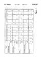
- FIG. 3is a table indicating states of various operating parameters and the presently preferred states of outputs of the control system depicted in FIG. 2 when rear wheel slip is within an acceptable range or when the vehicle is not equipped for control based on wheel slip;
- FIG. 4is a table indicating states of various operating parameters and the presently preferred states of outputs of the control system when the vehicle is equipped for slip-based control and rear wheel slip exceeds a predetermined threshold level.
- tractor and control circuit described hereinare adapted for control of both mechanical front wheel drive (MFD) and differential locking (DIFFLOCK) of the driven wheels, these two functions may be divided between separate controllers and, where desired, MFD or DIFFLOCK control may be provided alone.
- MFDmechanical front wheel drive
- DIFFLOCKdifferential locking
- the present systemfeatures a novel control scheme that significantly reduces the need for operator intervention in engaging, disengaging and re-engaging DIFFLOCK and MFD circuits and mechanisms.
- Such mechanismsare generally biased on or off, that is, engaged or disengaged, based upon the desired default state of the mechanism in the event of failure of a controller or other important elements in the control system.
- the control systemmust generally provide signals tending to move the corresponding devices to their non-biased state, removing these signals where the biased state is desired.
- Tractor 12represented in double-dashed lines, includes a rear axle 14 coupled to rear wheels 16, 18 and a front axle 20 coupled to front wheels 22.
- An engine 24provides power for driving rear wheels 16, 18 through a transmission 26 and differential 28 coupled to rear axle 14.
- engine 24may be selectively coupled to front wheels 22 to provide additional traction when necessary.
- Further power transmission elementsmay be coupled to engine 24 and transmission 26 for driving implements and performing auxiliary functions, such as via a power take off drive (not shown).
- Left and right service brakes 30 and 32are provided on axle 14 for independently braking rear wheels 16 and 18 respectively.
- Brakes 30 and 32are coupled to independent brake peddles through a power assist circuit of conventional design (not shown). Brakes 30 and 32 may be applied simultaneously to limit the rotation of both rear wheels 16, 18 for stopping, or either brake may be operated alone, such as for steering.
- Tractor 12may include an implement positioning device 34, such as a three-point hitch, for raising and lowering an implement 36, such as a ground-working implement.
- tractor 12may include a draw-bar arrangement capable of towing an implement 36, in which case implement positioning device 34 may be included on the towed implement. In the latter case, tractor 12 is considered to include the towed implement for the purposes of control system 10.
- Implement positioning device 34is generally responsive to operator-induced commands through a hitch or implement control system (not shown) of generally known design.
- differential 28permits relative velocity between rear wheels 16 and 18, that is, differential 28 allows rear wheels 16 and 18 to turn at different speeds. Such relative velocity may result incidentally during driving, such as during cornering due to the different turn radii of wheels 16 and 18.
- an operatormay expressly cause wheels 16 and 18 to rotate at different speeds, such as for steering, by application of a single service brake 30 or 32.
- the use of differential 28 and brakes 30 and 32 for steeringis common, for example, for tight cornering or routine steering corrections during field work, particularly in furrowed fields.
- Differential 28is coupled to a differential locking mechanism (DIFFLOCK mechanism) 38 for selectively limiting the relative velocity between rear wheels 16 and 18.
- DIFFLOCK mechanism 38is preferably of conventional design, such as the locking mechanism currently installed on the 7200 series tractors manufactured by Case Corporation of Racine, Wis.
- DIFFLOCK mechanism 38typically includes a control valve 40 coupled to the tractor's hydraulic system and actuated by a solenoid coil 42, and a multi-disc hydraulic clutch 44 in fluid communication with control valve 40.
- Control valve 40is spring-biased in a closed position whereby clutch 44 is not under fluid pressure and is thus disengaged when solenoid coil 42 is not energized. Thus, clutch 44 defaults to a disengaged state.
- valve 40In operation, when valve 40 receives electrical control signals from a control circuit 56, solenoid coil 42 is energized to shift valve 40 to an open position, routing pressurized fluid to clutch 44 for engagement, i.e. differential locking action.
- DIFFLOCK mechanism 38may include an electric clutch or other locking device capable of selectively preventing differential action between wheels 16 and 18 in response to electrical signals from control circuit 56.
- front wheels 22may be coupled to engine 24 through transmission 26 and a drive train including gearing 46 and an MFD engagement circuit 48.
- Engagement circuit 48is preferably of known construction, such as currently available on the 7200 series tractors manufactured by Case Corporation.
- engagement circuit 48typically includes a control valve 50 coupled to the tractor's hydraulic system and actuated by a solenoid coil 52, and a multi-disc hydraulic clutch 54 in fluid communication with valve 50.
- Control valve 50is spring-biased in an open position, whereby clutch 54 is engaged when solenoid coil 52 is not energized.
- clutch 54defaults to an engaged state whereby front wheels 22 are driven by engine 24 such that in the event of failure of solenoid coil 52 or any component communicating signals to coil 52, clutch 54 is engaged.
- Clutch 54may be selectively disengaged to uncouple engine 24 from axle 20 by applying control signals from control circuit 56 to valve 50 to energize solenoid coil 52 and shift valve 50 to its closed position.
- MFD engagement circuit 48may include an electric clutch arranged to complete or to interrupt the drive train between engine 24 and front wheels 22 in response to control signals from control circuit 56.
- front axle 20may include an MFD differential, similar to differential 28, permitting front wheels 22 to rotate at different speeds when clutch 54 is engaged.
- a differential locking arrangement similar to that coupled to differential 28may also be provided to selectively prevent differential action of the MFD drive.
- control system 10includes a control circuit 56 configured to generate control signals for engaging and disengaging DIFFLOCK mechanism 38 and MFD engagement circuit 48 based upon the state of certain operating parameters of tractor 12.
- Control system 10further includes a number of sensors and sensing circuits for detecting operating parameters of tractor 12 and generating signals representative thereof. These signals are communicated to control circuit 56 and are processed to determine the desired state of DIFFLOCK mechanism 38 and MFD engagement circuit 48, i.e. engaged or disengaged. Based upon these desired states, control circuit 56 applies appropriate engagement and disengagement control signals to mechanism 38 and circuit 48.
- control system 10includes the following parameter sensors and sensing circuits: brake detecting circuits 58 and 60, left and fight rear wheel velocity sensors 62 and 64, true ground speed sensor 66, front wheel velocity sensor 68 as an alternative to ground speed sensor 66 and an implement position detecting circuit 70.
- Brake detecting circuits 58 and 60are coupled to left and right service brakes 30 and 32 respectively and generate signals representative of the current state of the brakes.
- brake detecting circuits 58, 60may include electrical switches arranged to produce a signal when the associated brake is engaged and no signal when the brake is disengaged.
- Wheel velocity sensors 62 and 64are provided for detecting the rotational speed of rear wheels 16 and 18.
- Velocity sensors 62 and 64preferably include variable inductance type magnetic proximity sensors associated with timing or drive gears for producing pulsed signals, the frequencies of which are proportional to the rotational speed of wheels 16 and 18.
- True ground speed sensor 66such as a radar emitter and receiver unit, is mounted to tractor 12 and configured to generate signals representative of the tractor speed.
- true ground speed sensor 66may be of the type optionally available on the 7200 series tractors manufactured by Case Corporation.
- wheel velocity sensor 68which is essentially identical to velocity sensors 62 and 64 may be provided for sensing the rotational speed of front wheels 22 as an indication of ground speed.
- Implement position detecting circuit 70is coupled to implement positioning device 34 and generates signals representative of the actual position of implement 36.
- Implement position detecting circuit 70may include a potentiometer, linear variable differential transformer, or similar device for producing a signal proportional to the implement position. It should be noted that the present system preferably considers actual implement position for DIFFLOCK and MFD control, as opposed to an operator set position command or desired position value. Because implement positioning devices 34 generally respond to position command changes with some delay and may not reflect the actual implement position, it has been found that the use of actual implement position provides a more timely and reliable input for DIFFLOCK and MFD engagement and disengagement decisions. However, in particular applications where actual implement position cannot be sensed or no unacceptable time delay exists between position command changes and actual implement position changes, an operator set position command value could be considered by control circuit 56 for the present control purposes.
- sensors 58, 60, 62, 64, 66, 68 and 70are coupled to control circuit 56 via data links 72, 74, 76, 78, 80, 82 and 84 respectively and apply signals to control circuit 56 over these links.
- control circuit 56is coupled to DIFFLOCK mechanism 38 and to MFD engagement circuit 48 via conductors 86 and 88 respectively.
- An MFD switch 90 and a DIFFLOCK switch 92are also coupled to control circuit 56 via conductors 94 and 96 respectively.
- MFD switch 90is a three-position switch with positions corresponding to "MFD OFF", "MFD ON" and "AUTO" mode.
- DIFFLOCK switch 92is also preferably a three-position switch with positions corresponding to "OFF", "AUTO” and a momentary contact position “MOMENTARY ON”. Both MFD switch 90 and DIFFLOCK switch 92 are located in a control console in the tractor cab (not shown) and coupled to the tractor's electrical supply system for completing circuits to control circuit 56 when actuated by an operator. In operation, control circuit 56 continuously cycles through a control routine in which it monitors the status of switches 90 and 92. If either switch is in its "AUTO" position, control circuit 56 generates control signals corresponding to the desired states of DIFFLOCK mechanism 38 and MFD engagement circuit 48, i.e.
- control signalsare applied to mechanism 38 and circuit 48 via conductors 86 and 88 to complete the control function by engaging or disengaging mechanism 38 and circuit 48.
- DIFFLOCK and MFD switches 92 and 90permits automatic control of mechanism 38 and circuit 48 as well as more conventional manual selection or override of the state of these devices.
- DIFFLOCK switch 92is momentarily depressed to its "MOMENTARY ON” position, DIFFLOCK mechanism 38 is engaged without the intermediary of control circuit 56. Thereafter, mechanism 38 remains engaged until one or both service brakes 30, 32 are applied.
- DIFFLOCK switch 92is placed in its "OFF" position, mechanism 38 disengages and remains disengaged.
- MFD engagement circuit 48is engaged and remains engaged until switch 90 is moved out of the "ON” position.
- switch 90is placed in its "OFF” position, circuit 48 is disengaged.
- MFD engagement circuit 48is engaged temporarily during simultaneous application of both service brakes 30 and 32, to provide positive braking at all four wheels.
- switches 90 and 92thus offer an operator the option of disabling or overriding control circuit 56.
- switches 90 and 92allow an operator to command engagement and disengagement of DIFFLOCK mechanism 38 and MFD engagement circuit 48 as in existing equipment.
- switch configuration described aboveis preferred, similar disabling and override functions can be achieved with alternative switch arrangements, such as two separate switches for overriding (i.e. enabling and disabling) automatic control for manual engagement and disengagement and for selecting automatic control if enabled.
- FIG. 2illustrates the typical interrelation of the various components of control system 10 as well as the flow of signals between these components.
- Control circuit 56includes a control signal processing circuit 98, an operator interface circuit 100, a memory circuit 102, a slip signal transformation circuit 104 and a switch status monitoring circuit 106, all of which may be incorporated into an appropriately configured microprocessor.
- Operator interface circuit 104permits interruption of the normal operation of control circuit 56, such as for diagnostic functions and calibration of control system 10.
- Interface circuit 100is preferably coupled to a control console in the tractor cab through which an operator may input calibration data and check or monitor the status of various calibration values and operating parameters.
- Memory circuit 102typically includes read only memory circuits (ROM) configured to store the program executed by circuit 98, electronically erasable programmable read only memory circuits (EEPROM) configured to store calibration values used in executing the control functions and random access memory (RAM) configured to temporarily store values required for execution of the control routine.
- ROMread only memory circuits
- EEPROMelectronically erasable programmable read only memory circuits
- RAMrandom access memory
- Slip signal transformation circuit 104is configured to receive inputs related to vehicle and wheel speeds, to compare and process these values and to generate a slip signal representative of the slip of driven wheels 16 and 18 as will be described in greater detail below.
- switch status monitoring circuit 106monitors the operator-set status (i.e. position) of MFD and differential lock switches 90 and 92 and transmits this information to circuit 98 for modifying the control functions executed by control system 10 accordingly.
- Left and right brake detecting circuits 58 and 60are coupled to control circuit 56 via associated conditioning circuits 108 and 110 respectively, which may be integral to control circuit 56. Circuits 108 and 110 provides appropriate filtering to eliminate switch bounce. However, depending upon the control circuit 56 and the circuits 58 and 60 used to generate the braking signals, circuits 108 and 110 may be eliminated. The signals produced by circuits 58 and 60, conditioned by circuits 108 and 110, are applied to digital inputs of circuit 98. Similarly, implement position detecting circuit 70 is coupled to control circuit 56 through conditioning circuit 112 and the conditioned signal representative of the position of implement 36 is applied to a digital input of circuit 98.
- conditioning circuits 114, 116, 118 and 120are coupled to slip signal transformation circuit 104 through conditioning circuits 114, 116, 118 and 120 respectively. These conditioning circuits filter radio and other undesirable frequencies or interference from the signals produced to the associated sensors. Additionally, as required by the particular sensors used, conditioning circuits 114, 116, 118 and 120 place the signals produced by the sensors within a 5 volt range and provide these signals with a generally squarewave configuration which can be appropriately sampled by transformation circuit 104.
- Control circuit 56is configured to apply control signals to DIFFLOCK mechanism 38 through an appropriate amplification and signal conditioning circuit 122.
- control circuit 56applies an "on/off" signal to solenoid coil 42 of valve 40 through circuit 122 causing clutch 44 to receive pressurized fluid and thus to engage, limiting differential action of differential 28.
- control valve 40may be a proportional valve capable of throttling the supply of pressurized fluid to clutch 44 and control circuit may be configured to provide pulse-width-modulated (PWM) control signals to coil 42. Where control circuit 56 applies such PWM signals to coil 42, the duty cycle of the signals may be varied to obtain particular engagement and disengagement rates or characteristics (e.g. ramped).
- an indicator 124is provided in the tractor cab and coupled to control circuit 56.
- An energizing signalis supplied to illuminate indicator 124 whenever control circuit 56 supplies a signal tending to engage DIFFLOCK mechanism 38, thereby informing the vehicle operator that mechanism 38 is engaged.
- control circuit 56provides control signals to MFD engagement circuit 48 via an amplification and signal conditioning circuit 126. While these control signals are generally "on/off" signals for engaging or disengaging clutch 54 by energizing or de-energizing coil 52 to shift valve 50, valve 50 may be a proportional valve and control circuit 56 may provide PWM signals, the duty cycle of which may be varied for control of the engagement and disengagement rates of MFD engagement circuit 48.
- an MFD engagement indicator 128is provided in the tractor cab and coupled to control circuit 56. Indicator 128 receives an energizing signal from control circuit 56 whenever a control signal is output tending to engage MFD engagement circuit 48, thereby informing the operator that circuit 48 is engaged.
- Control system 10uses information related to wheel and vehicle velocity to calculate a degree of wheel slip in each cycle through its control routine.
- wheel velocity sensors 62 and 64provide signals representative of the rotational speed of rear wheels 16 and 18.
- a single sensormay be associated with the rear axle 14 and a signal from that sensor used to calculate wheel slip.
- Wheel velocity signals generated by sensors 62 and 64are related to apparent vehicle velocity in slip signal transformation circuit 104 by first converting the signals to a rotational velocity value (e.g. by dividing the signal pulse rate by the number of teeth on the timing gear associated with the sensor). This rotational velocity value is then converted into an apparent vehicle velocity value by multiplying the rotational velocity value by the circumference of rear wheels 16 and 18.
- the circumference value used in this stepis preferably generated from a wheel diameter value stored in memory circuit 102 during initial calibration of control system 10.
- the apparent vehicle velocity valueis then subtracted from a true vehicle velocity value generated directly from the signal received from ground speed sensor 66 to obtain a wheel slip value.
- the resulting slip valueis divided by the true vehicle velocity value to obtain a percentage slip value.
- front wheel velocity sensor 68may be used to provide an indication of vehicle ground speed. Where front wheel velocity sensor 68 is used, ground speed is computed in circuit 104 by first dividing the pulse rate of the signal generated by sensor 68 by the number of teeth in the timing gear associated with the sensor, and multiplying the resulting value by the circumference of the front wheels 22 (e.g. based on a front wheel diameter value stored in memory circuit 102 during calibration of control system 10).
- control circuit 56an important operating parameter considered by control circuit 56 for engagement, disengagement and re-engagement of DIFFLOCK mechanism 38 and MFD engagement circuit 48 is vehicle speed or true ground speed.
- control circuit 56utilizes the detected vehicle speed for generating a value of wheel slip, the vehicle speed value is also transmitted to signal processing circuit 98 for automatic control of mechanism 38 and circuit 48 as will be described below.
- Control logic particularly suited for implementation by control system 10will now be described with reference to FIGS. 3 and 4.
- Control system 10permits engagement, disengagement and re-engagement of DIFFLOCK mechanism 38 and MFD engagement circuit 48 in response to the state of a number of different operating parameters of tractor 12. While the specific parameters on which control system 10 bases control decisions regarding engagement of mechanism 38 and circuit 48 may vary, in the presently preferred embodiment these parameters include implement position, braking conditions, vehicle speed and wheel slip. Other parameters, such as steering angle and implement draft force, may be included in the control logic implemented by control system 10 with corresponding sensors and signal conditioning circuits being provided for supplying control circuit 56 with information related to the state of such parameters.
- control system 10may be configured for control based upon more or fewer parameter state inputs depending upon the type of vehicle being controlled and typical conditions anticipated.
- control system 10may be installed on vehicles without slip-based control, i.e. not equipped for sensing vehicle and wheel velocities or controlling based upon the degree of wheel slip.
- FIG. 3indicates the desired states of mechanism 38 and circuit 48 for various scenarios or combinations of parameter states when slip-based control is installed and wheel slip is within an acceptable range, i.e. below a predetermined threshold level.
- FIG. 4shows the desired states of mechanism 38 and circuit 48 when control system 10 is equipped for slip-based control and slip exceeds a predetermined threshold level.
- control system 10monitors implement position as sensed by detecting circuit 70 and classifies this position as either "high” or "low".
- An implementis generally considered to be in high position when it is above a predetermined threshold height, which may be expressed as a percentage of its total travel, such as 90%. Positions below that threshold are considered “low”.
- a "low" implement positionis considered indicative that work is currently being performed by the vehicle, such as plowing, grading or the like.
- Three possible braking conditionsare considered by control system 10, including "none”, “single” and “double”, depending upon the number of rear service brakes currently applied. Application of either left or right service brake 30, 32 alone is considered indicative of steering adjustments.
- Control system 10monitors vehicle speed as computed by transformation circuit 104 from signals from ground speed sensor 66, or from wheel velocity sensor 68 if present. Alternatively, the output of a speedometer could supply this parameter input. However, where the vehicle is equipped for slip-based control it is generally more convenient to use the vehicle velocity value generated by transformation circuit 104. A vehicle speed above a predetermined level, such as 7 miles per hour, is considered “high”, whereas speeds below that level are considered “low”. For vehicles equipped for slip-based control, control system 10 generally considers slip to be either "high” (i.e. above a predetermined threshold, such as 15%) or "low” (i.e. below the threshold).
- the various threshold levelsmay be stored permanently in memory circuit 102 or may be configured into memory circuit 102 during calibration of control system 10. Moreover, it is possible to re, configure or update the various threshold levels during a subsequent calibration of control system 10. Alternatively, all or some of the threshold levels may be operator-set, such as by command potentiometers on a control console in the vehicle cab.
- DIFFLOCK mechanism 38may be selectively disengaged by an operator by setting DIFFLOCK switch 92 to the "OFF" position.
- switch 92may be used to disable mechanism 38.
- an operatormay manually engage mechanism 38 by momentarily depressing switch 92 in the "MOMENTARY ON” position. Once manually engaged in this manner, DIFFLOCK mechanism 38 will remain engaged until one or both of service brakes 30, 32 are used, at which time mechanism 38 will be disengaged.
- an operatormay select automatic control of engagement, disengagement and re-engagement of DIFFLOCK mechanism 38 by placing switch 92 into the "AUTO" position.
- control circuit 56When control circuit 56 detects that DIFFLOCK switch 92 is in the "AUTO" position, control circuit 56 generates control signals for engaging, disengaging and re-engaging mechanism 38 based upon the state of one or more operating parameters as shown in FIGS. 3 and 4.
- FIG. 3illustrates the preferred states of DIFFLOCK mechanism 38 for various possible combinations of states for implement position, braking and vehicle speed when wheel slip is below a predetermined threshold level, such as 15%, or when the vehicle being controlled is not equipped for slip-based control.
- FIG. 4shows the preferred states of DIFFLOCK mechanism 38 for the same combinations of parameter states when the vehicle is equipped for slip-based control and wheel slip exceeds the threshold level.
- DIFFLOCK mechanism 38when wheel slip is below the threshold value, DIFFLOCK mechanism 38 is disengaged in all cases where the implement position is high (cases 1-6 in FIG. 3). In addition, mechanism 38 is disengaged when one or more service brakes is applied (cases 3-6 and 9-12). Finally, mechanism 38 is disengaged when the vehicle speed is found to be above the preset level discussed above, such as 7 miles per hour (cases 1, 3, 5, 7, 9 and 11). Consequently, in the presently preferred embodiment, when slip is below a predetermined slip threshold, or the vehicle is not equipped for slip-based control, mechanism 38 is engaged in a single combination of parameter conditions, designated case 8 in FIG. 3.
- differential locking mechanism 38is disengaged by control circuit 56. Such disengagement may occur, for example, during application of a single brake, such as for steering adjustments, during implement raising, such as at the headlands of a field during a half turn, or during higher speed movement of the tractor in a field. If, following such disengagement of mechanism 38, control circuit 56 detects that parameter conditions once again match those required for engagement (i.e. case 8 in FIG. 3), mechanism 38 is re-engaged.
- the present systemalleviates the need for an operator to reset DIFFLOCK mechanism 38 following routine manoeuver.
- control system 10may cause engagement and re-engagement of DIFFLOCK mechanism 38 in an additional situation as compared with the scenarios considered above.
- This additional situationdesignated case 2 in FIG. 4, occurs when the implement is raised, neither service brake is applied and the vehicle ground speed is below the threshold speed. Because this combination of parameter states typically occurs when tractor 12 is being turned, as at a headland, without the assistance of a service brake, it has been found desirable to engage DIFFLOCK mechanism 38 should wheel slip become excessive. Should control circuit 56 detect any change in parameter conditions resulting in a combination different from cases 2 and 8 it commands disengagement of mechanism 38.
- control circuit 56detects that conditions once again match either of cases 2 or 8 and wheel slip exceeds the predetermined threshold, control circuit 56 commands re-engagement of mechanism 38. Similarly, if conditions match case 2 in FIG. 4 and slip temporarily falls below the slip threshold, control circuit 56 disengages mechanism 38. Thereafter, control circuit 56 will re-engage mechanism 38 if slip again exceeds the threshold or if the implement is lowered, resulting in case 8 in FIG. 3.
- Control system 10engages and disengages MFD engagement circuit 48 as follows. As discussed above, when MFD switch 90 is in its "OFF” position, circuit 48 is disengaged, but is engaged temporarily during simultaneous application of both service brakes 30 and 32 to provide positive braking at all four wheels. Thus, switch 90 may at least partially disable circuit 48. When MFD switch 90 is in its "ON” position, circuit 48 is continuously engaged. These manually controlled “OFF” and “ON” states of circuit 48 do not require intervention of control circuit 56. However, when MFD switch 90 is in its "AUTO” position, circuit 48 is engaged, disengaged and re-engaged automatically by control circuit 56 without requiring further operator intervention as discussed below.
- control circuit 56When control circuit 56 detects that MFD switch 90 is in the "AUTO" position, control circuit 56 generates control signals for engaging, disengaging and re-engaging MFD engagement circuit 48 depending upon the current state of one or more operating parameters as illustrated in FIGS. 3 and 4. As illustrated in FIG. 3, control circuit 56 commands engagement of circuit 48 during application of both service brakes 30 and 32, regardless of the state of other operating parameters such as implement position and vehicle speed (cases 5, 6, 11 and 12 in FIG. 3).
- control circuit 56commands engagement of circuit 48 when implement 36 is in a lowered position, neither or a single service brake is applied and the vehicle is travelling at a speed below the predetermined speed threshold (cases 8 and 10). Because the latter two cases generally occur as work is being performed by the vehicle, without and with single brake-assisted steering adjustments respectively, it has been found beneficial to provide traction at all wheels by engagement of circuit 48. As shown in FIG. 4, when tractor 12 is equipped for slip-based control and slip exceeds a predetermined threshold, control circuit 56 commands engagement of circuit 48 in all parameter state combinations.
- control circuit 56When operating conditions cause any of the above conditions to change, resulting in a case other than 5, 6, 8, 10, 11 or 12 in FIG. 3, or reducing wheel slip to below the slip threshold, control circuit 56 commands circuit 48 to disengage. If, following such disengagement, control circuit 56 detects that conditions again correspond to one of the combinations for which MFD engagement is desirable, control circuit 56 commands re-engagement of circuit 48.
- hysteresisis preferably programmed into all differential lock and MFD engagement, disengagement and re-engagement decisions discussed above, to enhance stability of the system and reduce hunting.
- Such hysteresisgenerally requires that parameter changes that would cause control system 10 to alter the state of mechanism 38 or circuit 48 must subsist for a given time, such as 0.5 seconds, or number of control routine cycles, such as 5 successive cycles of 100 milliseconds, before being given effect.
- parameter valuesmay be required to fall below or to exceed the associated parameter threshold by a predetermined amount before being considered to change the state of the parameter.
- a signal representative of the current state of DIFFLOCK mechanism 38is applied as an input for automatic MFD control by control circuit 56.
- MFD engagement circuit 48is commanded to engage any time DIFFLOCK mechanism 38 is engaged.
- control circuit 56commands engagement of MFD engagement circuit 48 as well.
Landscapes
- Engineering & Computer Science (AREA)
- Transportation (AREA)
- Mechanical Engineering (AREA)
- Chemical & Material Sciences (AREA)
- Combustion & Propulsion (AREA)
- Regulating Braking Force (AREA)
- Arrangement And Driving Of Transmission Devices (AREA)
Abstract
Description
Claims (32)
Priority Applications (1)
| Application Number | Priority Date | Filing Date | Title |
|---|---|---|---|
| US08/338,409US5505267A (en) | 1994-11-14 | 1994-11-14 | Differential lock control system for agricultural vehicles |
Applications Claiming Priority (1)
| Application Number | Priority Date | Filing Date | Title |
|---|---|---|---|
| US08/338,409US5505267A (en) | 1994-11-14 | 1994-11-14 | Differential lock control system for agricultural vehicles |
Publications (1)
| Publication Number | Publication Date |
|---|---|
| US5505267Atrue US5505267A (en) | 1996-04-09 |
Family
ID=23324717
Family Applications (1)
| Application Number | Title | Priority Date | Filing Date |
|---|---|---|---|
| US08/338,409Expired - LifetimeUS5505267A (en) | 1994-11-14 | 1994-11-14 | Differential lock control system for agricultural vehicles |
Country Status (1)
| Country | Link |
|---|---|
| US (1) | US5505267A (en) |
Cited By (59)
| Publication number | Priority date | Publication date | Assignee | Title |
|---|---|---|---|---|
| US5676219A (en)* | 1994-07-29 | 1997-10-14 | Steyr-Daimler-Puck Aktiengesellschaft | System for controlling the axle differential locks of automotive vehicles |
| FR2750367A1 (en)* | 1996-07-01 | 1998-01-02 | Claas Ohg | DEVICE AND METHOD FOR AUTOMATICALLY CONTROLLING DIFFERENTIAL BLOCKING ON A MOTOR VEHICLE |
| US5802489A (en)* | 1994-11-14 | 1998-09-01 | Case Corporation | Front wheel drive engagement control system for agricultural vehicles |
| WO1999003035A1 (en)* | 1997-07-07 | 1999-01-21 | Case Corporation | Sequential command repeater system for off-road vehicles |
| US5865700A (en)* | 1997-05-01 | 1999-02-02 | Case Corporation | Hydro-mechanical transmission |
| WO1999021065A1 (en)* | 1997-10-23 | 1999-04-29 | Tooling Technology Centre (U.S.), Inc. | Control system for powered cargo bed |
| US5927422A (en)* | 1997-06-12 | 1999-07-27 | Meritor Heavy Vehicle Systems, L L C | Method and apparatus for correcting drive wheel slip |
| US5995895A (en)* | 1997-07-15 | 1999-11-30 | Case Corporation | Control of vehicular systems in response to anticipated conditions predicted using predetermined geo-referenced maps |
| US6041867A (en)* | 1996-08-09 | 2000-03-28 | Case Corporation | Hitch initialization control system |
| US6058342A (en)* | 1996-07-25 | 2000-05-02 | Case Corporation | Precision control of implement position/motion |
| US6059383A (en)* | 1997-03-07 | 2000-05-09 | Same Deutz-Fahr S.P.A. | Braking control system for agricultural tractors |
| US6085138A (en)* | 1998-11-12 | 2000-07-04 | Caterpillar Inc. | Differential lock control system |
| US6092013A (en)* | 1999-04-20 | 2000-07-18 | Case Corporation | Multiple setpoint power takeoff control system |
| US6099090A (en)* | 1997-03-07 | 2000-08-08 | Same Deutz-Fahr S.P.A. | Breaking control system for agricultural tractors |
| US6099088A (en)* | 1998-09-28 | 2000-08-08 | Caterpillar Inc. | Traction assembly for a work machine |
| US6142059A (en)* | 1996-11-27 | 2000-11-07 | Case Corporation | Method and apparatus for sensing the orientation of a mechanical actuator |
| US6174255B1 (en)* | 1999-10-05 | 2001-01-16 | Deere & Company | Differential lock control system for articulated work vehicle |
| US6354978B1 (en) | 1999-10-26 | 2002-03-12 | Simplicity Manufacturing, Inc. | Differential and method for variable traction control |
| US6434462B1 (en)* | 2001-06-28 | 2002-08-13 | Deere & Company | GPS control of a tractor-towed implement |
| US6565471B2 (en) | 2000-12-19 | 2003-05-20 | Case Corporation | Continuously variable hydro-mechanical transmission |
| US6722260B1 (en) | 2002-12-11 | 2004-04-20 | Rosemount Inc. | Hydraulic piston position sensor |
| US6722261B1 (en) | 2002-12-11 | 2004-04-20 | Rosemount Inc. | Hydraulic piston position sensor signal processing |
| US20040195018A1 (en)* | 2003-04-02 | 2004-10-07 | Akira Inui | Floor arrangement for off-road vehicle |
| US20040195028A1 (en)* | 2003-04-02 | 2004-10-07 | Kazuhiko Izumi | Drive system for off-road vehicle |
| US20040206567A1 (en)* | 2003-04-02 | 2004-10-21 | Eiji Kato | Frame arrangement for off-road vehicle |
| US20040216945A1 (en)* | 2003-04-02 | 2004-11-04 | Akira Inui | Steering system for off-road vehicle |
| US6820712B2 (en) | 2000-12-07 | 2004-11-23 | Yamaha Hatsudoki Kabushiki Kaisha | Differential locking control system |
| US20070205660A1 (en)* | 2006-01-20 | 2007-09-06 | J. C. Bamford Excavators Limited | Working Machine |
| US7287619B2 (en) | 2003-04-02 | 2007-10-30 | Yamaha Hatsudoki Kabushiki Kaisha | Air intake system for off-road vehicle |
| US20080004778A1 (en)* | 2006-06-30 | 2008-01-03 | Andrew Karl Wilhelm Rekow | System and method for calculating instantaneous placement corrections to achieve towed implement placement on curved paths |
| US20080015065A1 (en)* | 2003-04-02 | 2008-01-17 | Yamaha Hatsudoki Kabushiki Kaisha | Transmission for off-road vehicle |
| US20080015066A1 (en)* | 2003-04-02 | 2008-01-17 | Yamaha Hatsudoki Kabushiki Kaisha | Off-road vehicle with air intake system |
| US20080027610A1 (en)* | 2006-07-31 | 2008-01-31 | Caterpillar Inc. | System for controlling implement position |
| US20080135322A1 (en)* | 2006-12-08 | 2008-06-12 | Smith Brent A | Differential lock control system and associated method |
| US20080255735A1 (en)* | 2007-04-11 | 2008-10-16 | Marathe Sameer S | Traction control method in machine using lockable differential |
| US7510199B2 (en) | 2003-04-02 | 2009-03-31 | Yamaha Hatsudoki Kabushiki Kaisha | Off-road vehicle with wheel suspension |
| US20100094516A1 (en)* | 2008-10-10 | 2010-04-15 | Toyota Jidosha Kabushiki Kaisha | Vehicle control device and vehicle control method |
| US20100228457A1 (en)* | 2007-06-01 | 2010-09-09 | Reiter Dennis P | Momentary Activation Of Mechanical Front Wheel Drive |
| US20110202244A1 (en)* | 2008-10-23 | 2011-08-18 | Zf Friedrichshafen Ag | Method for operating the torque converter lock-up clutch in a power transmission of a mobile machine comprising at least one hydraulically actuated lifting device |
| US8098054B2 (en) | 2007-10-10 | 2012-01-17 | John Alexander Verschuur | Optimal load controller method and device |
| US20120221222A1 (en)* | 2011-02-28 | 2012-08-30 | Eric Anderson | Method of compensating for vehicle kinematics in controlling independent wheel motors |
| CN103158713A (en)* | 2013-03-11 | 2013-06-19 | 河南科技大学 | Tractor intelligent control method and intelligent control system |
| US8626410B2 (en) | 2012-01-23 | 2014-01-07 | Caterpillar Inc. | Powertrain system having lockable differential |
| US8663058B2 (en) | 2012-01-23 | 2014-03-04 | Caterpillar Inc. | Brake assembly having piloted park brake housing |
| US20140095043A1 (en)* | 2012-09-28 | 2014-04-03 | Claas Tractor S.A.S. | Method for operating a self-propelled agricultural machine |
| US20140128196A1 (en)* | 2011-06-14 | 2014-05-08 | Valtra Oy Ab | Continuously variable power-split vehicle transmission |
| US9169884B2 (en) | 2012-01-23 | 2015-10-27 | Caterpillar Inc. | Wet brake assembly |
| US20170013773A1 (en)* | 2015-07-14 | 2017-01-19 | Clemson University | Automated Control Systems and Methods for Underground Crop Harvesters |
| US9709969B2 (en) | 2013-03-15 | 2017-07-18 | Deere & Company | Methods and apparatus to control machine configurations |
| EP3202243A1 (en)* | 2016-02-02 | 2017-08-09 | AGCO International GmbH | Vehicle implement control |
| US9845008B2 (en) | 2015-09-03 | 2017-12-19 | Deere & Company | System and method of detecting load forces on a traction vehicle to predict wheel slip |
| US9994104B2 (en) | 2015-09-03 | 2018-06-12 | Deere & Company | System and method of reacting to wheel slip in a traction vehicle |
| US10071729B2 (en)* | 2016-05-16 | 2018-09-11 | Ford Global Technologies, Llc | Tow damping system |
| US10112615B2 (en) | 2015-09-03 | 2018-10-30 | Deere & Company | System and method of reacting to wheel slip in a traction vehicle |
| US10144409B2 (en)* | 2016-01-20 | 2018-12-04 | Komatsu Ltd. | Engine control device of work machine, work machine, and engine control method of work machine |
| US10407072B2 (en) | 2015-09-03 | 2019-09-10 | Deere & Company | System and method of regulating wheel slip in a traction vehicle |
| US10959365B2 (en) | 2018-08-14 | 2021-03-30 | Cnh Industrial America Llc | System and method for controlling the position of an agricultural implement by applying a braking force to a wheel of the implement |
| US11407308B1 (en)* | 2021-06-09 | 2022-08-09 | Ford Global Technologies, Llc | System and method for operating vehicle in selected vehicle mode |
| US20220252484A1 (en)* | 2019-02-26 | 2022-08-11 | Continental Automotive Gmbh | Method for authorising updating of a magnetic sensor for a combustion engine with immunity to magnetic disturbances |
Citations (13)
| Publication number | Priority date | Publication date | Assignee | Title |
|---|---|---|---|---|
| US2874790A (en)* | 1957-07-03 | 1959-02-24 | Int Harvester Co | Steering by driving with differential lock-out bull gear coupling |
| US3081836A (en)* | 1959-05-30 | 1963-03-19 | Ferguson Res Ltd Harry | Vehicle braking control |
| US4088208A (en)* | 1976-10-26 | 1978-05-09 | International Harvester Company | Transmission disconnect system |
| US4218938A (en)* | 1977-07-25 | 1980-08-26 | Kabushiki Kaisha Komatsu Seisakusho | Control system for a differential gear lock mechanism |
| US4344499A (en)* | 1978-12-08 | 1982-08-17 | C. Van Der Lely N.V. | Tractor with anti-slipping and overloading controls |
| US4347760A (en)* | 1980-01-25 | 1982-09-07 | Massey-Ferguson, Inc. | Locking differential control system |
| US4454919A (en)* | 1980-12-13 | 1984-06-19 | Robert Bosch Gmbh | Agricultural tractor-trailer slippage recognition system and method |
| US4589511A (en)* | 1983-06-14 | 1986-05-20 | Robert Bosch Gmbh | All-wheel drive automotive vehicle traction control system |
| US4715012A (en)* | 1980-10-15 | 1987-12-22 | Massey-Ferguson Services N.V. | Electronic tractor control |
| US4746173A (en)* | 1985-10-02 | 1988-05-24 | Alfred Teves Gmbh | Slip-controlled brake system for all-wheel driven automotive vehicle |
| US4895217A (en)* | 1986-12-20 | 1990-01-23 | Deere & Company | Drive system for two pairs of wheels |
| US5297649A (en)* | 1988-08-23 | 1994-03-29 | Shigeru Yamamoto | Apparatus for controlling output from engine on crawler type tractor |
| US5421416A (en)* | 1993-09-08 | 1995-06-06 | Case Corporation | Hitch assembly control system |
- 1994
- 1994-11-14USUS08/338,409patent/US5505267A/ennot_activeExpired - Lifetime
Patent Citations (13)
| Publication number | Priority date | Publication date | Assignee | Title |
|---|---|---|---|---|
| US2874790A (en)* | 1957-07-03 | 1959-02-24 | Int Harvester Co | Steering by driving with differential lock-out bull gear coupling |
| US3081836A (en)* | 1959-05-30 | 1963-03-19 | Ferguson Res Ltd Harry | Vehicle braking control |
| US4088208A (en)* | 1976-10-26 | 1978-05-09 | International Harvester Company | Transmission disconnect system |
| US4218938A (en)* | 1977-07-25 | 1980-08-26 | Kabushiki Kaisha Komatsu Seisakusho | Control system for a differential gear lock mechanism |
| US4344499A (en)* | 1978-12-08 | 1982-08-17 | C. Van Der Lely N.V. | Tractor with anti-slipping and overloading controls |
| US4347760A (en)* | 1980-01-25 | 1982-09-07 | Massey-Ferguson, Inc. | Locking differential control system |
| US4715012A (en)* | 1980-10-15 | 1987-12-22 | Massey-Ferguson Services N.V. | Electronic tractor control |
| US4454919A (en)* | 1980-12-13 | 1984-06-19 | Robert Bosch Gmbh | Agricultural tractor-trailer slippage recognition system and method |
| US4589511A (en)* | 1983-06-14 | 1986-05-20 | Robert Bosch Gmbh | All-wheel drive automotive vehicle traction control system |
| US4746173A (en)* | 1985-10-02 | 1988-05-24 | Alfred Teves Gmbh | Slip-controlled brake system for all-wheel driven automotive vehicle |
| US4895217A (en)* | 1986-12-20 | 1990-01-23 | Deere & Company | Drive system for two pairs of wheels |
| US5297649A (en)* | 1988-08-23 | 1994-03-29 | Shigeru Yamamoto | Apparatus for controlling output from engine on crawler type tractor |
| US5421416A (en)* | 1993-09-08 | 1995-06-06 | Case Corporation | Hitch assembly control system |
Non-Patent Citations (2)
| Title |
|---|
| Massey Ferguson 3600 MF 3000 Series Tractors.* |
| Massey-Ferguson 3600 MF 3000 Series Tractors. |
Cited By (93)
| Publication number | Priority date | Publication date | Assignee | Title |
|---|---|---|---|---|
| US5676219A (en)* | 1994-07-29 | 1997-10-14 | Steyr-Daimler-Puck Aktiengesellschaft | System for controlling the axle differential locks of automotive vehicles |
| US5802489A (en)* | 1994-11-14 | 1998-09-01 | Case Corporation | Front wheel drive engagement control system for agricultural vehicles |
| FR2750367A1 (en)* | 1996-07-01 | 1998-01-02 | Claas Ohg | DEVICE AND METHOD FOR AUTOMATICALLY CONTROLLING DIFFERENTIAL BLOCKING ON A MOTOR VEHICLE |
| US6058342A (en)* | 1996-07-25 | 2000-05-02 | Case Corporation | Precision control of implement position/motion |
| US6041867A (en)* | 1996-08-09 | 2000-03-28 | Case Corporation | Hitch initialization control system |
| US6142059A (en)* | 1996-11-27 | 2000-11-07 | Case Corporation | Method and apparatus for sensing the orientation of a mechanical actuator |
| US6099090A (en)* | 1997-03-07 | 2000-08-08 | Same Deutz-Fahr S.P.A. | Breaking control system for agricultural tractors |
| US6059383A (en)* | 1997-03-07 | 2000-05-09 | Same Deutz-Fahr S.P.A. | Braking control system for agricultural tractors |
| US5865700A (en)* | 1997-05-01 | 1999-02-02 | Case Corporation | Hydro-mechanical transmission |
| USRE37458E1 (en) | 1997-05-01 | 2001-11-27 | Case Corporation | Hydro-mechanical transmission |
| US5927422A (en)* | 1997-06-12 | 1999-07-27 | Meritor Heavy Vehicle Systems, L L C | Method and apparatus for correcting drive wheel slip |
| WO1999003035A1 (en)* | 1997-07-07 | 1999-01-21 | Case Corporation | Sequential command repeater system for off-road vehicles |
| US5899950A (en)* | 1997-07-07 | 1999-05-04 | Case Corporation | Sequential command repeater system for off-road vehicles |
| US5995895A (en)* | 1997-07-15 | 1999-11-30 | Case Corporation | Control of vehicular systems in response to anticipated conditions predicted using predetermined geo-referenced maps |
| WO1999021065A1 (en)* | 1997-10-23 | 1999-04-29 | Tooling Technology Centre (U.S.), Inc. | Control system for powered cargo bed |
| US6099088A (en)* | 1998-09-28 | 2000-08-08 | Caterpillar Inc. | Traction assembly for a work machine |
| US6085138A (en)* | 1998-11-12 | 2000-07-04 | Caterpillar Inc. | Differential lock control system |
| US6205385B1 (en) | 1999-04-20 | 2001-03-20 | Case Corporation | Power takeoff control switches |
| US6173225B1 (en) | 1999-04-20 | 2001-01-09 | Case Corporation | Power takeoff control system |
| US6092013A (en)* | 1999-04-20 | 2000-07-18 | Case Corporation | Multiple setpoint power takeoff control system |
| US6174255B1 (en)* | 1999-10-05 | 2001-01-16 | Deere & Company | Differential lock control system for articulated work vehicle |
| US6354978B1 (en) | 1999-10-26 | 2002-03-12 | Simplicity Manufacturing, Inc. | Differential and method for variable traction control |
| US6820712B2 (en) | 2000-12-07 | 2004-11-23 | Yamaha Hatsudoki Kabushiki Kaisha | Differential locking control system |
| US6565471B2 (en) | 2000-12-19 | 2003-05-20 | Case Corporation | Continuously variable hydro-mechanical transmission |
| US20030109347A1 (en)* | 2000-12-19 | 2003-06-12 | Case Corporation | Continuously variable hydro-mechanical transmission |
| US7063638B2 (en) | 2000-12-19 | 2006-06-20 | Cnh America Llc | Continuously variable hydro-mechanical transmission |
| US20060003861A1 (en)* | 2000-12-19 | 2006-01-05 | Weeramantry Cecil A | Continuously variable hydro-mechanical transmission |
| US20050043133A1 (en)* | 2000-12-19 | 2005-02-24 | Weeramantry Cecil A. | Continuously variable hydro-mechanical transmission |
| US6852056B2 (en) | 2000-12-19 | 2005-02-08 | Cnh America Llc | Continuously variable hydro-mechanical transmission |
| US6434462B1 (en)* | 2001-06-28 | 2002-08-13 | Deere & Company | GPS control of a tractor-towed implement |
| US6722261B1 (en) | 2002-12-11 | 2004-04-20 | Rosemount Inc. | Hydraulic piston position sensor signal processing |
| US6722260B1 (en) | 2002-12-11 | 2004-04-20 | Rosemount Inc. | Hydraulic piston position sensor |
| US7690462B2 (en) | 2003-04-02 | 2010-04-06 | Yamaha Hatsudoki Kabushiki Kaisha | Off-road vehicle with air intake system |
| US7717206B2 (en) | 2003-04-02 | 2010-05-18 | Yamaha Hatsudoki Kabushiki Kaisha | Air intake system for off-road vehicle |
| US20040195018A1 (en)* | 2003-04-02 | 2004-10-07 | Akira Inui | Floor arrangement for off-road vehicle |
| US7690472B2 (en) | 2003-04-02 | 2010-04-06 | Yamaha Hatsudoki Kabushiki Kaisha | Transmission for off-road vehicle |
| US7147076B2 (en) | 2003-04-02 | 2006-12-12 | Yamaha Hatsudoki Kabushiki Kaisha | Drive system for off-road vehicle |
| US20040216945A1 (en)* | 2003-04-02 | 2004-11-04 | Akira Inui | Steering system for off-road vehicle |
| US7287619B2 (en) | 2003-04-02 | 2007-10-30 | Yamaha Hatsudoki Kabushiki Kaisha | Air intake system for off-road vehicle |
| US7506712B2 (en) | 2003-04-02 | 2009-03-24 | Yamaha Hatsudoki Kabushiki Kaisha | Off road vehicle with air intake system |
| US20040195028A1 (en)* | 2003-04-02 | 2004-10-07 | Kazuhiko Izumi | Drive system for off-road vehicle |
| US20080015065A1 (en)* | 2003-04-02 | 2008-01-17 | Yamaha Hatsudoki Kabushiki Kaisha | Transmission for off-road vehicle |
| US20080015066A1 (en)* | 2003-04-02 | 2008-01-17 | Yamaha Hatsudoki Kabushiki Kaisha | Off-road vehicle with air intake system |
| US20080053727A1 (en)* | 2003-04-02 | 2008-03-06 | Yamaha Hatsudoki Kabushiki Kaisha | Air intake system for off-road vehicle |
| US7357211B2 (en) | 2003-04-02 | 2008-04-15 | Yamaha Hatsudoki Kabushiki Kaisha | Steering system for off-road vehicle |
| US7367417B2 (en) | 2003-04-02 | 2008-05-06 | Yamaha Hatsudoki Kabushiki Kaisha | Floor arrangement for off-road vehicle |
| US20040206567A1 (en)* | 2003-04-02 | 2004-10-21 | Eiji Kato | Frame arrangement for off-road vehicle |
| US7650959B2 (en) | 2003-04-02 | 2010-01-26 | Yamaha Hatsudoki Kabushiki Kaisha | Frame arrangement for off-road vehicle |
| US7438147B2 (en) | 2003-04-02 | 2008-10-21 | Yamaha Hatsudoki Kabushiki Kaisha | Transmission for off-road vehicle |
| US7510199B2 (en) | 2003-04-02 | 2009-03-31 | Yamaha Hatsudoki Kabushiki Kaisha | Off-road vehicle with wheel suspension |
| US20070205660A1 (en)* | 2006-01-20 | 2007-09-06 | J. C. Bamford Excavators Limited | Working Machine |
| US7509199B2 (en)* | 2006-06-30 | 2009-03-24 | Deere & Company | System and method for calculating instantaneous placement corrections to achieve towed implement placement on curved paths |
| US20080004778A1 (en)* | 2006-06-30 | 2008-01-03 | Andrew Karl Wilhelm Rekow | System and method for calculating instantaneous placement corrections to achieve towed implement placement on curved paths |
| US7725234B2 (en)* | 2006-07-31 | 2010-05-25 | Caterpillar Inc. | System for controlling implement position |
| US20080027610A1 (en)* | 2006-07-31 | 2008-01-31 | Caterpillar Inc. | System for controlling implement position |
| US20080135322A1 (en)* | 2006-12-08 | 2008-06-12 | Smith Brent A | Differential lock control system and associated method |
| US7650961B2 (en) | 2006-12-08 | 2010-01-26 | Deere & Company | Differential lock control system and associated method |
| US20080255735A1 (en)* | 2007-04-11 | 2008-10-16 | Marathe Sameer S | Traction control method in machine using lockable differential |
| US7770681B2 (en)* | 2007-04-11 | 2010-08-10 | Caterpillar Inc | Traction control method in machine using lockable differential |
| US8504250B2 (en) | 2007-06-01 | 2013-08-06 | Deere & Company | Momentary activation of mechanical front wheel drive |
| US20100228457A1 (en)* | 2007-06-01 | 2010-09-09 | Reiter Dennis P | Momentary Activation Of Mechanical Front Wheel Drive |
| US8098054B2 (en) | 2007-10-10 | 2012-01-17 | John Alexander Verschuur | Optimal load controller method and device |
| US8014926B2 (en)* | 2008-10-10 | 2011-09-06 | Toyota Jidosha Kabushiki Kaisha | Vehicle control device |
| US20100094516A1 (en)* | 2008-10-10 | 2010-04-15 | Toyota Jidosha Kabushiki Kaisha | Vehicle control device and vehicle control method |
| US20110202244A1 (en)* | 2008-10-23 | 2011-08-18 | Zf Friedrichshafen Ag | Method for operating the torque converter lock-up clutch in a power transmission of a mobile machine comprising at least one hydraulically actuated lifting device |
| CN102197244B (en)* | 2008-10-23 | 2014-06-25 | Zf腓德烈斯哈芬股份公司 | A method for operating a torque converter lock-up clutch |
| US8494735B2 (en)* | 2008-10-23 | 2013-07-23 | Zf Friedrichshafen Ag | Method for operating the torque converter lock-up clutch in a power transmission of a mobile machine comprising at least one hydraulically actuated lifting device |
| US20120221222A1 (en)* | 2011-02-28 | 2012-08-30 | Eric Anderson | Method of compensating for vehicle kinematics in controlling independent wheel motors |
| US20140128196A1 (en)* | 2011-06-14 | 2014-05-08 | Valtra Oy Ab | Continuously variable power-split vehicle transmission |
| US8626410B2 (en) | 2012-01-23 | 2014-01-07 | Caterpillar Inc. | Powertrain system having lockable differential |
| US8663058B2 (en) | 2012-01-23 | 2014-03-04 | Caterpillar Inc. | Brake assembly having piloted park brake housing |
| US9169884B2 (en) | 2012-01-23 | 2015-10-27 | Caterpillar Inc. | Wet brake assembly |
| US20140095043A1 (en)* | 2012-09-28 | 2014-04-03 | Claas Tractor S.A.S. | Method for operating a self-propelled agricultural machine |
| RU2635930C2 (en)* | 2012-09-28 | 2017-11-17 | КЛААС Трактор С.А.С. | Self-propelled agricultural machine, control method and system of such machine |
| US9221434B2 (en)* | 2012-09-28 | 2015-12-29 | Claas Tractor S.A.S. | Method for operating a self-propelled agricultural machine |
| CN103158713A (en)* | 2013-03-11 | 2013-06-19 | 河南科技大学 | Tractor intelligent control method and intelligent control system |
| CN103158713B (en)* | 2013-03-11 | 2016-02-10 | 河南科技大学 | A kind of trac. intelligent control method and intelligent control system |
| US9709969B2 (en) | 2013-03-15 | 2017-07-18 | Deere & Company | Methods and apparatus to control machine configurations |
| US11422519B2 (en) | 2013-03-15 | 2022-08-23 | Deere & Company | Methods and apparatus to control machine configurations |
| US10539935B2 (en) | 2013-03-15 | 2020-01-21 | Deere & Company | Methods and apparatus to control machine configurations |
| US20170013773A1 (en)* | 2015-07-14 | 2017-01-19 | Clemson University | Automated Control Systems and Methods for Underground Crop Harvesters |
| US9968027B2 (en)* | 2015-07-14 | 2018-05-15 | Clemson University | Automated control systems and methods for underground crop harvesters |
| US10112615B2 (en) | 2015-09-03 | 2018-10-30 | Deere & Company | System and method of reacting to wheel slip in a traction vehicle |
| US9994104B2 (en) | 2015-09-03 | 2018-06-12 | Deere & Company | System and method of reacting to wheel slip in a traction vehicle |
| US10407072B2 (en) | 2015-09-03 | 2019-09-10 | Deere & Company | System and method of regulating wheel slip in a traction vehicle |
| US9845008B2 (en) | 2015-09-03 | 2017-12-19 | Deere & Company | System and method of detecting load forces on a traction vehicle to predict wheel slip |
| US10144409B2 (en)* | 2016-01-20 | 2018-12-04 | Komatsu Ltd. | Engine control device of work machine, work machine, and engine control method of work machine |
| EP3202243A1 (en)* | 2016-02-02 | 2017-08-09 | AGCO International GmbH | Vehicle implement control |
| US10071729B2 (en)* | 2016-05-16 | 2018-09-11 | Ford Global Technologies, Llc | Tow damping system |
| US10959365B2 (en) | 2018-08-14 | 2021-03-30 | Cnh Industrial America Llc | System and method for controlling the position of an agricultural implement by applying a braking force to a wheel of the implement |
| US20220252484A1 (en)* | 2019-02-26 | 2022-08-11 | Continental Automotive Gmbh | Method for authorising updating of a magnetic sensor for a combustion engine with immunity to magnetic disturbances |
| US12140498B2 (en)* | 2019-02-26 | 2024-11-12 | Continental Automotive Gmbh | Method for authorising updating of a magnetic sensor for a combustion engine with immunity to magnetic disturbances |
| US11407308B1 (en)* | 2021-06-09 | 2022-08-09 | Ford Global Technologies, Llc | System and method for operating vehicle in selected vehicle mode |
Similar Documents
| Publication | Publication Date | Title |
|---|---|---|
| US5505267A (en) | Differential lock control system for agricultural vehicles | |
| US5802489A (en) | Front wheel drive engagement control system for agricultural vehicles | |
| US6085138A (en) | Differential lock control system | |
| US6058342A (en) | Precision control of implement position/motion | |
| US5810095A (en) | System for controlling the position of an implement attached to a work vehicle | |
| EP2475558B1 (en) | A vehicle with brake steering | |
| US5911769A (en) | Hitch assembly control system with slip control | |
| US6109384A (en) | Vehicle front wheel speed change apparatus | |
| US7729830B2 (en) | Vehicle control system | |
| US6058343A (en) | Threshold current control system for hydraulic valves | |
| US5684691A (en) | Method and apparatus for controlling draft of an agricultural implement | |
| US5558163A (en) | Control system for utility vehicle | |
| EP2384941B1 (en) | Method for braking and braking system of an externally braked device | |
| DE19982568B3 (en) | System for protecting powertrain components from excessive engine inertial forces | |
| US6016875A (en) | Gain adaptation control for hydraulic systems | |
| US9050890B2 (en) | Vehicle positioning system | |
| US7684918B2 (en) | PTO brake control system | |
| DE102013221948A1 (en) | Steering-based vehicle speed control system and corresponding method | |
| US5755291A (en) | Operator interface for vehicle control system with slip regulation | |
| DE102013106548A1 (en) | Agricultural vehicle | |
| EP0394390B1 (en) | Vehicle with multiple driven axles | |
| DE60033251T2 (en) | Steering for tracked vehicle steering with steering pump monitoring | |
| EP1358784B1 (en) | Agricultural vehicle | |
| EP1270306B1 (en) | Control of starting and stopping of a PTO shaft in an agricultural vehicle | |
| US6041867A (en) | Hitch initialization control system |
Legal Events
| Date | Code | Title | Description |
|---|---|---|---|
| AS | Assignment | Owner name:CASE CORPORATION, WISCONSIN Free format text:ASSIGNMENT OF ASSIGNORS INTEREST;ASSIGNORS:ORBACH, ABRAHAM;SCHUBERT, WILLIAM L.;REEL/FRAME:007227/0619 Effective date:19941103 | |
| STCF | Information on status: patent grant | Free format text:PATENTED CASE | |
| FPAY | Fee payment | Year of fee payment:4 | |
| REMI | Maintenance fee reminder mailed | ||
| FPAY | Fee payment | Year of fee payment:8 | |
| SULP | Surcharge for late payment | Year of fee payment:7 | |
| AS | Assignment | Owner name:CNH AMERICA LLC, PENNSYLVANIA Free format text:ASSIGNMENT OF ASSIGNORS INTEREST;ASSIGNOR:CASE CORPORATION;REEL/FRAME:014981/0944 Effective date:20040805 | |
| AS | Assignment | Owner name:CNH AMERICA LLC, PENNSYLVANIA Free format text:ASSIGNMENT OF ASSIGNORS INTEREST;ASSIGNOR:CNH AMERICA LLC;REEL/FRAME:017766/0484 Effective date:20060606 Owner name:BLUE LEAF I.P., INC., DELAWARE Free format text:ASSIGNMENT OF ASSIGNORS INTEREST;ASSIGNOR:CNH AMERICA LLC;REEL/FRAME:017766/0484 Effective date:20060606 | |
| FPAY | Fee payment | Year of fee payment:12 |