US5504378A - Direct cooled switching module for electric vehicle propulsion system - Google Patents
Direct cooled switching module for electric vehicle propulsion systemDownload PDFInfo
- Publication number
- US5504378A US5504378AUS08/258,027US25802794AUS5504378AUS 5504378 AUS5504378 AUS 5504378AUS 25802794 AUS25802794 AUS 25802794AUS 5504378 AUS5504378 AUS 5504378A
- Authority
- US
- United States
- Prior art keywords
- heat sink
- switching
- passage
- module
- conductive
- Prior art date
- Legal status (The legal status is an assumption and is not a legal conclusion. Google has not performed a legal analysis and makes no representation as to the accuracy of the status listed.)
- Expired - Lifetime
Links
Images


Classifications
- H—ELECTRICITY
- H05—ELECTRIC TECHNIQUES NOT OTHERWISE PROVIDED FOR
- H05K—PRINTED CIRCUITS; CASINGS OR CONSTRUCTIONAL DETAILS OF ELECTRIC APPARATUS; MANUFACTURE OF ASSEMBLAGES OF ELECTRICAL COMPONENTS
- H05K7/00—Constructional details common to different types of electric apparatus
- H05K7/20—Modifications to facilitate cooling, ventilating, or heating
- H05K7/2089—Modifications to facilitate cooling, ventilating, or heating for power electronics, e.g. for inverters for controlling motor
- H05K7/20927—Liquid coolant without phase change
- H—ELECTRICITY
- H02—GENERATION; CONVERSION OR DISTRIBUTION OF ELECTRIC POWER
- H02M—APPARATUS FOR CONVERSION BETWEEN AC AND AC, BETWEEN AC AND DC, OR BETWEEN DC AND DC, AND FOR USE WITH MAINS OR SIMILAR POWER SUPPLY SYSTEMS; CONVERSION OF DC OR AC INPUT POWER INTO SURGE OUTPUT POWER; CONTROL OR REGULATION THEREOF
- H02M7/00—Conversion of AC power input into DC power output; Conversion of DC power input into AC power output
- H02M7/003—Constructional details, e.g. physical layout, assembly, wiring or busbar connections
- H—ELECTRICITY
- H01—ELECTRIC ELEMENTS
- H01L—SEMICONDUCTOR DEVICES NOT COVERED BY CLASS H10
- H01L2224/00—Indexing scheme for arrangements for connecting or disconnecting semiconductor or solid-state bodies and methods related thereto as covered by H01L24/00
- H01L2224/01—Means for bonding being attached to, or being formed on, the surface to be connected, e.g. chip-to-package, die-attach, "first-level" interconnects; Manufacturing methods related thereto
- H01L2224/42—Wire connectors; Manufacturing methods related thereto
- H01L2224/47—Structure, shape, material or disposition of the wire connectors after the connecting process
- H01L2224/48—Structure, shape, material or disposition of the wire connectors after the connecting process of an individual wire connector
- H01L2224/4805—Shape
- H01L2224/4809—Loop shape
- H01L2224/48091—Arched
- H—ELECTRICITY
- H01—ELECTRIC ELEMENTS
- H01L—SEMICONDUCTOR DEVICES NOT COVERED BY CLASS H10
- H01L2224/00—Indexing scheme for arrangements for connecting or disconnecting semiconductor or solid-state bodies and methods related thereto as covered by H01L24/00
- H01L2224/01—Means for bonding being attached to, or being formed on, the surface to be connected, e.g. chip-to-package, die-attach, "first-level" interconnects; Manufacturing methods related thereto
- H01L2224/42—Wire connectors; Manufacturing methods related thereto
- H01L2224/47—Structure, shape, material or disposition of the wire connectors after the connecting process
- H01L2224/48—Structure, shape, material or disposition of the wire connectors after the connecting process of an individual wire connector
- H01L2224/481—Disposition
- H01L2224/48151—Connecting between a semiconductor or solid-state body and an item not being a semiconductor or solid-state body, e.g. chip-to-substrate, chip-to-passive
- H01L2224/48221—Connecting between a semiconductor or solid-state body and an item not being a semiconductor or solid-state body, e.g. chip-to-substrate, chip-to-passive the body and the item being stacked
- H01L2224/48225—Connecting between a semiconductor or solid-state body and an item not being a semiconductor or solid-state body, e.g. chip-to-substrate, chip-to-passive the body and the item being stacked the item being non-metallic, e.g. insulating substrate with or without metallisation
- H01L2224/48227—Connecting between a semiconductor or solid-state body and an item not being a semiconductor or solid-state body, e.g. chip-to-substrate, chip-to-passive the body and the item being stacked the item being non-metallic, e.g. insulating substrate with or without metallisation connecting the wire to a bond pad of the item
- H—ELECTRICITY
- H01—ELECTRIC ELEMENTS
- H01L—SEMICONDUCTOR DEVICES NOT COVERED BY CLASS H10
- H01L2224/00—Indexing scheme for arrangements for connecting or disconnecting semiconductor or solid-state bodies and methods related thereto as covered by H01L24/00
- H01L2224/01—Means for bonding being attached to, or being formed on, the surface to be connected, e.g. chip-to-package, die-attach, "first-level" interconnects; Manufacturing methods related thereto
- H01L2224/42—Wire connectors; Manufacturing methods related thereto
- H01L2224/47—Structure, shape, material or disposition of the wire connectors after the connecting process
- H01L2224/49—Structure, shape, material or disposition of the wire connectors after the connecting process of a plurality of wire connectors
- H01L2224/491—Disposition
- H01L2224/49105—Connecting at different heights
- H01L2224/49109—Connecting at different heights outside the semiconductor or solid-state body
- H—ELECTRICITY
- H01—ELECTRIC ELEMENTS
- H01L—SEMICONDUCTOR DEVICES NOT COVERED BY CLASS H10
- H01L2924/00—Indexing scheme for arrangements or methods for connecting or disconnecting semiconductor or solid-state bodies as covered by H01L24/00
- H01L2924/01—Chemical elements
- H01L2924/01004—Beryllium [Be]
- H—ELECTRICITY
- H01—ELECTRIC ELEMENTS
- H01L—SEMICONDUCTOR DEVICES NOT COVERED BY CLASS H10
- H01L2924/00—Indexing scheme for arrangements or methods for connecting or disconnecting semiconductor or solid-state bodies as covered by H01L24/00
- H01L2924/10—Details of semiconductor or other solid state devices to be connected
- H01L2924/11—Device type
- H01L2924/13—Discrete devices, e.g. 3 terminal devices
- H01L2924/1304—Transistor
- H01L2924/1305—Bipolar Junction Transistor [BJT]
- H01L2924/13055—Insulated gate bipolar transistor [IGBT]
- H—ELECTRICITY
- H01—ELECTRIC ELEMENTS
- H01L—SEMICONDUCTOR DEVICES NOT COVERED BY CLASS H10
- H01L2924/00—Indexing scheme for arrangements or methods for connecting or disconnecting semiconductor or solid-state bodies as covered by H01L24/00
- H01L2924/15—Details of package parts other than the semiconductor or other solid state devices to be connected
- H01L2924/161—Cap
- H01L2924/162—Disposition
- H01L2924/1627—Disposition stacked type assemblies, e.g. stacked multi-cavities
- H—ELECTRICITY
- H01—ELECTRIC ELEMENTS
- H01L—SEMICONDUCTOR DEVICES NOT COVERED BY CLASS H10
- H01L2924/00—Indexing scheme for arrangements or methods for connecting or disconnecting semiconductor or solid-state bodies as covered by H01L24/00
- H01L2924/19—Details of hybrid assemblies other than the semiconductor or other solid state devices to be connected
- H01L2924/1901—Structure
- H01L2924/1904—Component type
- H01L2924/19041—Component type being a capacitor
- H—ELECTRICITY
- H01—ELECTRIC ELEMENTS
- H01L—SEMICONDUCTOR DEVICES NOT COVERED BY CLASS H10
- H01L2924/00—Indexing scheme for arrangements or methods for connecting or disconnecting semiconductor or solid-state bodies as covered by H01L24/00
- H01L2924/30—Technical effects
- H01L2924/301—Electrical effects
- H01L2924/30107—Inductance
Definitions
- This inventiongenerally relates to switching circuits, and particularly relates to fluid-cooled switching circuits, e.g., insulated gate bipolar transistor (IGBT) circuits, for use in electric vehicles. While the invention is subject to a wide range of applications, it is especially suited for use in electric vehicles that utilize batteries or a combination of batteries and other sources, e.g., a heat engine coupled to an alternator, as a source of power, and will be particularly described in that connection.
- IGBTinsulated gate bipolar transistor
- Conventional electric vehiclesinclude a motor, a battery, and a group of electronic components for charging the battery and operating the motor.
- electric vehicles(not including the battery pack) have been designed to be generally lighter than gasoline-powered vehicles, the addition of a suitable battery pack increases the weight of a typical electric vehicle such that a substantial amount of power must be utilized in the motor to move the vehicle. Because of "iron” losses in the magnetic parts of the motor and resistance to the current flow in the electrical conductors of the motor, heat is generated in the motor during use. If this heat is not removed, the potential for failure of the motor components exists.
- the vehicle's propulsion systemmust incorporate switching circuits that switch large currents to drive the motor. These large currents cause an undesirable generation of heat within the electrical components of conventional electrical vehicles.
- the motor controller within a conventional electric vehicle system control unitmay include a switching circuit having a number of IGBT's, among other components.
- the IGBT'srapidly switch on and off to direct current flow to the motor, using a substantial amount of current and generating heat. Therefore, some method of removing thermal energy from the IGBT's is required to prevent their potential failure, as well as the potential failure of other electrical components located nearby.
- a directed flow of airhas been used to cool electrical components in conventional electric vehicles. However, such air flow provides insufficient cooling in some situations, particularly in high-performance applications.
- the present inventionis directed to a fluid-cooled switching module for an electric vehicle that substantially obviates one or more of the problems due to the limitations and disadvantages of the related art.
- the inventionprovides for apparatus comprising first and second heat sinks, each having two thermally-conductive planar members forming a passage therebetween for channeling cooling fluid, an inlet port in communication with the passage, and an outlet port in communication with the passage, means for mounting at least one switching element to each of the first and second heat sinks, means for connecting the switching element attached to the first heat sink in series with the switching element attached to the second heat sink, and means, coupled to the inlet and outlet ports of the first and second heat sinks, for circulating cooling fluid through the passages of the first and second heat sinks to cool the switching elements.
- the inventionprovides for a switching module comprising upper and lower mounting assemblies, each mounting assembly including a heat sink having a top surface, two thermally-conductive planar members forming a passage therebetween for channeling cooling fluid, an inlet port in communication with the passage, and an outlet port in communication with the passage, a first conductive member laminated to the top surface of the heat sink with a dielectric material, a second conductive member laminated to the first conductive member with a dielectric material, a plurality of thermally-conductive substrates attached to the top surface of the heat sink, a plurality of transistors attached to the heat sink via the plurality of substrates, each transistor having a collector connected to the first conductive member and an emitter connected to the second conductive member, means for connecting the second conductive member of the lower mounting assembly with the first conductive member of the upper mounting assembly, means for connecting the first conductive member of the lower mounting assembly to a positive voltage source, means for connecting the second conductive member of the upper mounting assembly to a common ground member, and means, communicating with
- the inventionprovides for a switching module assembly comprising a pair of switching modules, each switching module comprising upper and lower heat sinks, each heat sink having a passage for channeling cooling fluid, an inlet port in communication with the passage, and an outlet port in communication with the passage, at least one switching element attached to each of the upper and lower heat sinks, means for connecting the switching element attached to the upper heat sink in series with the switching element attached to the lower heat sink, and means for joining the upper heat sink with the lower heat sink in a spaced, parallel relationship; means, communicating with the inlet and outlet ports of the heat sinks of the pair of switching modules, for circulating cooling fluid through the heat sinks; and means for joining the pair of switching modules in an opposed, parallel relationship so that the lower heat sink of one of the modules faces the lower heat sink of the other module.
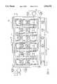
- FIG. 1is a block diagram of an electric vehicle propulsion system incorporating a switching module of the present invention
- FIG. 2is a functional diagram of the motor controller of the electric vehicle propulsion system of FIG. 1;
- FIG. 3is a schematic diagram of the power bridges of the motor controller of FIG. 2;
- FIG. 4is a plan view of a switching module for the motor controller of FIG. 2 in accordance with a preferred embodiment of the invention
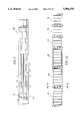
- FIG. 5is a cross-sectional view of the switching module of FIG. 4;
- FIGS. 6A and 6Bare partial sectional views of embodiments of the switching module of FIG. 4;
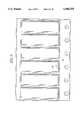
- FIG. 7is a bottom view of an upper planar member of the switching module of FIG. 4;
- FIGS. 8A and 8Bare plan views of embodiments of the substrates of the switching module of FIG. 4;
- FIG. 9is a plan view of collector and emitter plates of the switching module of FIG. 4.
- FIG. 10is a plan view of several switching modules, as shown in FIG. 4, nested together.
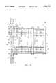
- FIG. 11is a cross-sectional view of a pair of switching modules taken along the lines 11--11 of FIG. 10;
- an electric vehicle propulsion system 10comprising a system control unit 12, a motor assembly 24, a cooling system 32, a battery 40, and a DC/DC converter 38.
- the system control unit 12includes a battery charger 16, a motor controller 18, a power distribution module 20, and a chassis controller 22.
- the motor assembly 24includes a resolver 26, a motor 28, and a filter 30.
- the cooling system 32includes an oil pump 34 and a radiator/fan 36.
- the motor controller 18uses switching circuits and other components to apply drive currents to windings of the motor 28.
- An exemplary embodiment of the motor controlleris shown in FIGS. 2 and 3.
- the motor controller 18includes a low voltage power supply 42, an input filter and DC relay control unit 44, a vector control board 46, and first and second power bridges 48 and 50, respectively.
- the first power bridge 48includes three IGBT switching circuits 52a, 52b, and 52c and the second power bridge 50 includes three IGBT switching circuits 53a, 53b, and 53c.
- the IGBT switching circuits 52a, 52b, and 52capply drive currents to windings A1, B1, and C1, respectively, of the motor 28.
- the IGBT switching circuits 53a, 53b, and 53capply drive currents to windings A2, B2, and C2, respectively, of the motor 28.
- Each of the IGBT switching circuits 52a, 52b, 52c, 53a, 53b, and 53cincludes IGBTs 54 and 56, respectively, diodes 58 and 60, respectively, and a capacitor 62 connected as shown in FIG. 3.
- the IGBT switching circuits 52a, 52b, 52c, 53a, 53b, and 53care all identical such that each of the first and second power bridges 48 and 50, respectively, provides half the total drive current to the windings of the motor 28.
- the IGBT switching circuits 52a, 52b, 52c, 53a, 53b, and 53ccan be replaced with other switching circuits known in the art.
- the first power bridge 48further includes three gate drive circuits 64a, 64b, and 64c and the second power bridge 50 further includes three gate drive circuits 65a, 65b, and 65c.
- the gate drive circuits 64a, 64b, and 64creceive pulse-width-modulated (PWM) voltage waveforms in the form of gate drive signals AU1 and AL1, gate drive signals BU1 and BL1, and gate drive signals CU1 and CL1, respectively, from the vector control board 46.
- the gate drive circuits 65a, 65b, and 65creceive PWM voltage waveforms in the form of gate drive signals AU2 and AL2, gate drive signals BU2 and BL2, and gate drive signals CU2 and CL2, respectively, from the vector control board 46.
- the gate drive circuits 64a, 64b, and 64c and the gate drive circuits 65a, 65b, and 65clevel-shift the received gate drive signals and apply the level-shifted gate drive signals to the IGBT switching circuits 52a, 52b, 52c, 53a, and 53c as shown in FIG. 3 to drive the IGBT switching circuits 52a, 52b, 52c, 53a, 53b, and 53c.
- each of the gate drive circuits 64a, 64b, 64c, 65a, 65b, and 65ccan comprise, for example, a Fuji EXB841 Gate Drive Hybrid or other similar device known in the art.
- FIG. 3illustrates switching circuits composed of one IGBT 54 and one IGBT 56
- a switching circuitmay include several IGBTs 54 connected in parallel and several IGBTs 56 connected in parallel for high power applications.
- the switching moduleincludes upper and lower mounting assemblies, each mounting assembly having a heat sink, a first conductive member laminated to the top surface of the heat sink with a dielectric material, a second conductive member laminated to the first conductive member with a dielectric material, a plurality of thermally-conductive substrates attached to the top surface of the heat sink, and a plurality of transistors attached to the heat sink via the plurality of substrates.
- upper mounting assembly 102includes a heat sink 104, a first conductive member or collector plate 106 laminated to the top surface of the heat sink 104 with a dielectric layer 108, a second conductive member or emitter plate 110 laminated to the collector plate with a second dielectric layer 112, and six thermally-conductive substrates 114 attached to the top surface of the heat sink.
- lower mounting assembly 120also includes a heat sink 122, a collector plate 124, a dielectric layer (not shown) similar to dielectric layer 108, an emitter plate 128, a second dielectric layer 130, and six thermally-conductive substrates 114.
- each heat sinkincludes an upper planar member 132 and a lower planar member 134 that are joined together by brazing. When the upper and lower planar members are joined, they define a passage therebetween for channeling cooling fluid, such as water or oil.
- the upper and lower planar membersare preferably composed of aluminum or other thermally-conductive metal, such as copper.
- the upper planar member 132preferably includes a plurality of grooves 136 and lands 140, while the planar member 134 is flat.
- the upper and lower planar membersform a plurality of parallel passages for allowing coolant to flow therebetween.
- FIG. 7illustrates six parallel passages, the number of passages is variable depending upon the number of substrates attached to the heat sink, as will be discussed below.
- Each passagehas an inlet 142 and an outlet 144.
- fins 146are secured to or made part of the upper planar member and extend into the parallel passages to increase heat transfer between the switching elements and the cooling fluid as it passes through the heat sink.
- the finscan be made of copper or other thermally-conductive material.
- the heat sinksalso include an inlet port 148 and an outlet port 150 that communicate with inlet and outlet manifolds 152 and 154 respectively to provide cooling fluid to the heat sinks, as shown in FIGS. 4, 5, 7, and 11. Cooling fluid is circulated through the heat sinks via the inlet and outlet manifolds by a pump, such as oil pump unit 34 shown in FIG. 1, or a separate circulation system that is well known in the art. As shown by paths A and B in FIG. 7, coolant enters the inlet port 148 and the inlet 142 of each parallel passage and exits via the outlet 144 of each passage and outlet port 150 so that the coolant temperature at each inlet of the parallel passages is substantially the same. The flow rate through each passage is the same because the pressure drop across each passage is the same.
- FIG. 10shows three small modules (with three transistor assemblies each) and three large modules (with six transistor assemblies each) nested together.
- the IGBTs 54, 56are incorporated into transistor dies 156a and 156b and diodes 58, 60 are incorporated into diode dies 158.
- an IGBTmay be incorporated into one transistor die 156a, or, as shown in FIG. 8B, may be incorporated into two transistor dies 156b. Dies containing IGBT's 54 are attached to the heat sink 122 of the lower mounting assembly and dies containing IGBT's 56 are attached to the heat sink 104 of the upper mounting assembly, as shown in FIG. 5.
- the substrates 114 supporting the transistor and diode diesare positioned on the heat sink above the parallel passages.
- a first metal layer 160such as copper
- a second metal layer 162such as copper
- the transistor die 156b and the diode die 158are attached to the second metal layer 162.
- the substrate 114which is preferably composed of beryllium oxide, the two metal layers, the transistor die, and the diode die are attached as an assembly to the heat sink 104.
- an additional metal layer 164preferably copper, is attached to the top surface of the heat sink before the substrate assembly is attached.
- collector plate 106is laminated to the top surface of the heat sink 104 with dielectric layer 108, which is preferably a dielectric preform adhesive. Since the emitter plate must be electrically insulated from the collector plate, the emitter plate 110 is laminated to the top of the collector plate with the second dielectric layer 112.
- the collector and emitter plates 124, 128 shown in FIG. 5are attached to heat sink 122 in a similar fashion so that the upper and lower mounting assemblies are identical in structure.
- the second metal layer 162is electrically and mechanically attached to the bottom surface of the transistor die 156b.
- the second metal layeris also wirebonded to the collector plate 106 so as to electrically connect the bottom surface of the transistor die 156b to the collector plate.
- the emitter connection to the transistor dieis on the top surface of the die in the form of a number of wirebonding pads, which are wirebonded to the emitter plate 110, as shown in FIGS. 4, 6A, and 6B.
- the collector and emitter platesare laminated together so that current in one is balanced by an equal current in the other flowing in the opposite direction, thus helping to reduce the mutual inductance in these conductive plates.
- current in the collector wirebondsis matched by current in the emitter wirebonds traveling in the opposite direction.
- the collector plate 106includes six rectangular cut-out portions for accommodating the mounting of the substrates onto the top surface of the heat sink 104.
- the second dielectric layer 112is constructed in a similar fashion, but has cut-out portions of a slightly larger area.
- the emitter plate 110has cut-out portions of a slightly larger area than the dielectric layer 112 to form a layered structure as shown in FIGS. 6A, 6B, and 9.
- the first dielectric layer 108which is not shown in FIG. 9, is similar in shape, but has cut-out portions slightly smaller than those of the collector plate.
- the upper and lower mounting assemblies 102 and 120 shown in FIG. 5are joined together as shown in FIG. 11.
- the collector and emitter plates of each mounting assemblyare sized so that they protrude from a side of the heat sink.
- the emitter plate 110is connected to a flange-shaped negative terminal 170 with screws 172 (only one shown).
- An L-shaped ac terminal 174is disposed between the two mounting assemblies and held in contact with the collector plate 106 of the upper mounting assembly 102 and the emitter plate 128 of the lower mounting assembly 120 also with screws 172. Screws 172 also connect collector plate 124 of the lower mounting assembly 120 to a U-shaped positive bus bar 176.
- the mounting assembliesare also separated by a pair of flanges 178 that are part of the inlet and outlet ports 148, 150.
- the flanges 178have o-ring grooves on each surface for sealing the coolant flow.
- the screws 172In order to make the respective connections, the screws 172 must be insulated from the ac terminal 174 and the negative terminal 170. This is done with cylindrical spacers 182 and flat washer type spacers 184. In order to keep the assembly tight, the screws 172 preferably use several conical spring washers 186 and screw into locking helical inserts (not shown) installed in the positive bus bar 176.
- the second dielectric layers 112, 130extend beyond the edges of the collector and emitter plates to provide a longer path for voltage margin.
- the two mounting assembliesneed not be permanently joined together, but rather they can be bolted together at the time of assembly to make the necessary connections to the bus bar, the negative terminal, and the ac terminal.
- a second switching module 200identical to the first switching module, can be added.
- the second switching moduleopposes the first (top) switching module 100 and is mounted on the opposite surfaces of the inlet and outlet manifolds 152, 154.
- Second switching moduleincludes upper and lower mounting assemblies 202, 220.
- the negative terminals 170, 270 and the positive bus bar 176are connected to a positive rail of a voltage source and a common ground plane.
- the ac terminals 174, 274are connected to an ac machine to supply the machine with electrical energy if it is acting as a motor or extract electrical energy from the machine if it is acting as a generator.
- a set of three switching modulesis required to connect to a three-phase ac machine.
- the three switching modulesare preferably on the same side of the manifolds 152, 154.
- the U-shaped bus bar 176is bolted to the positive rail 300 with electrically-conductive spacers 302 and screws 304.
- the negative terminals 170, 270are bolted to the common ground plane 310, which is attached to the positive rail 300 via an insulating layer (not shown), with screws 312. Finally, the ac terminals 174, 274 are connected to the ac rail 320, which is shown in FIG. 4.
- the completed assemblyrepresents a high-power switching device which can control high electric power by using liquid cooling placed close to the devices that generate heat.
Landscapes
- Engineering & Computer Science (AREA)
- Microelectronics & Electronic Packaging (AREA)
- Physics & Mathematics (AREA)
- Thermal Sciences (AREA)
- Power Engineering (AREA)
- Inverter Devices (AREA)
Abstract
Description
The following identified U.S. patent applications are filed on the same date as the instant application and are relied upon and incorporated by reference in this application.
U.S. patent application Ser. No. 08/258,295 entitled "Flat Topping Concept";
U.S. patent application Ser. No. 08/258,150 entitled "Electric Induction Motor And Related Method Of Cooling";
U.S. patent application Ser. No. 08/258,142 entitled "Automotive 12 Volt System For Electric Vehicles";
U.S. patent application Ser. No. 08/258,301 entitled "Electric Vehicle Propulsion System";
U.S. patent application Ser. No. 08/258,294 entitled "Speed Control and Bootstrap Technique For High Voltage Motor Control";
U.S. patent application Ser. No. 08/258,306 entitled "Vector Control Board For An Electric Vehicle Propulsion System Motor Controller";
U.S. patent application Ser. No. 08/258,305 entitled "Digital Pulse Width Modulator With Integrated Test And Control";
U.S. patent application Ser. No. 08/258,149 entitled "Control Mechanism For Electric Vehicle";
U.S. patent application Ser. No. 08/258,153 entitled "Improved EMI Filter Topology for Power Inverters";
U.S. patent application Ser. No. 08/258,179 entitled "Fault Detection Circuit For Sensing Leakage Currents Between Power Source And Chassis";
U.S. patent application Ser. No. 08/258,117 entitled "Electric Vehicle Relay Assembly";
U.S. patent application Ser. No. 08/258,033 entitled "Three Phase Power Bridge Assembly";
U.S. patent application Ser. No. 08/258,034 entitled "Electric Vehicle Propulsion System Power Bridge With Built-In-Test";
U.S. patent application Ser. No. 08/258,178 entitled "Method For Testing A Power Bridge For An Electric Vehicle Propulsion System";
U.S. patent application Ser. No. 08/258,157 entitled "Electric Vehicle Power Distribution Module";
U.S. patent application Ser. No. 08/258,628 entitled "Electric Vehicle Chassis Controller";
U.S. patent application Ser. No. 08/258,156 entitled "Electric Vehicle System Control Unit Housing";
U.S. patent application Ser. No. 08/258,299 entitled "Low Cost Fluid Cooled Housing For Electric Vehicle System Control Unit";
U.S. patent application Ser. No. 08/258,296 entitled "Electric Vehicle Coolant Pump Assembly";
U.S. patent application Ser. No. 08/258,141 entitled "Heat Dissipating Transformer Coil";
U.S. patent application Ser. No. 08/258,154 entitled "Electric Vehicle Battery Charger";
This invention generally relates to switching circuits, and particularly relates to fluid-cooled switching circuits, e.g., insulated gate bipolar transistor (IGBT) circuits, for use in electric vehicles. While the invention is subject to a wide range of applications, it is especially suited for use in electric vehicles that utilize batteries or a combination of batteries and other sources, e.g., a heat engine coupled to an alternator, as a source of power, and will be particularly described in that connection.
Due to the importance currently placed on conserving petroleum reserves, achieving energy efficiency, and reducing air pollution, development of electric vehicles has become a priority. Ultimately, to be successful, these vehicles must be safe, inexpensive, efficient, and acceptable to consumers who are used to driving gasoline-powered vehicles.
For an electric vehicle to be commercially viable, its cost and performance should be competitive with that of its gasoline-powered counterparts. Typically, the vehicle's propulsion system and battery are the main factors which contribute to the vehicle's cost and performance competitiveness.
Conventional electric vehicles include a motor, a battery, and a group of electronic components for charging the battery and operating the motor. Although electric vehicles (not including the battery pack) have been designed to be generally lighter than gasoline-powered vehicles, the addition of a suitable battery pack increases the weight of a typical electric vehicle such that a substantial amount of power must be utilized in the motor to move the vehicle. Because of "iron" losses in the magnetic parts of the motor and resistance to the current flow in the electrical conductors of the motor, heat is generated in the motor during use. If this heat is not removed, the potential for failure of the motor components exists.
In order to satisfy performance requirements, the vehicle's propulsion system must incorporate switching circuits that switch large currents to drive the motor. These large currents cause an undesirable generation of heat within the electrical components of conventional electrical vehicles. For example, the motor controller within a conventional electric vehicle system control unit may include a switching circuit having a number of IGBT's, among other components. The IGBT's rapidly switch on and off to direct current flow to the motor, using a substantial amount of current and generating heat. Therefore, some method of removing thermal energy from the IGBT's is required to prevent their potential failure, as well as the potential failure of other electrical components located nearby. A directed flow of air has been used to cool electrical components in conventional electric vehicles. However, such air flow provides insufficient cooling in some situations, particularly in high-performance applications.
Accordingly, the present invention is directed to a fluid-cooled switching module for an electric vehicle that substantially obviates one or more of the problems due to the limitations and disadvantages of the related art.
Features and advantages of the invention will be set forth in the description which follows, and in part will be apparent from the description, or may be learned by practice of the invention. The objectives and other advantages of the invention will be realized and attained by the apparatus particularly pointed out in the written description and claims thereof as well as the appended drawings.
To achieve these and other advantages and in accordance with the purpose of the invention, as embodied and broadly described, the invention provides for apparatus comprising first and second heat sinks, each having two thermally-conductive planar members forming a passage therebetween for channeling cooling fluid, an inlet port in communication with the passage, and an outlet port in communication with the passage, means for mounting at least one switching element to each of the first and second heat sinks, means for connecting the switching element attached to the first heat sink in series with the switching element attached to the second heat sink, and means, coupled to the inlet and outlet ports of the first and second heat sinks, for circulating cooling fluid through the passages of the first and second heat sinks to cool the switching elements.
In another aspect, the invention provides for a switching module comprising upper and lower mounting assemblies, each mounting assembly including a heat sink having a top surface, two thermally-conductive planar members forming a passage therebetween for channeling cooling fluid, an inlet port in communication with the passage, and an outlet port in communication with the passage, a first conductive member laminated to the top surface of the heat sink with a dielectric material, a second conductive member laminated to the first conductive member with a dielectric material, a plurality of thermally-conductive substrates attached to the top surface of the heat sink, a plurality of transistors attached to the heat sink via the plurality of substrates, each transistor having a collector connected to the first conductive member and an emitter connected to the second conductive member, means for connecting the second conductive member of the lower mounting assembly with the first conductive member of the upper mounting assembly, means for connecting the first conductive member of the lower mounting assembly to a positive voltage source, means for connecting the second conductive member of the upper mounting assembly to a common ground member, and means, communicating with the inlet and outlet ports of the heat sinks of the upper and lower mounting assemblies, for circulating cooling fluid through the heat sinks.
In a further aspect, the invention provides for a switching module assembly comprising a pair of switching modules, each switching module comprising upper and lower heat sinks, each heat sink having a passage for channeling cooling fluid, an inlet port in communication with the passage, and an outlet port in communication with the passage, at least one switching element attached to each of the upper and lower heat sinks, means for connecting the switching element attached to the upper heat sink in series with the switching element attached to the lower heat sink, and means for joining the upper heat sink with the lower heat sink in a spaced, parallel relationship; means, communicating with the inlet and outlet ports of the heat sinks of the pair of switching modules, for circulating cooling fluid through the heat sinks; and means for joining the pair of switching modules in an opposed, parallel relationship so that the lower heat sink of one of the modules faces the lower heat sink of the other module.
It is to be understood that both the foregoing general description and the following detailed description are exemplary and explanatory and are intended to provide further explanation of the invention as claimed.
The accompanying drawings, which are included to provide a further understanding of the invention and are incorporated in and constitute a part of this specification, illustrate a presently preferred embodiment of the invention and, together with the description, serve to explain the principles of the invention. In the drawings:
FIG. 1 is a block diagram of an electric vehicle propulsion system incorporating a switching module of the present invention;
FIG. 2 is a functional diagram of the motor controller of the electric vehicle propulsion system of FIG. 1;
FIG. 3 is a schematic diagram of the power bridges of the motor controller of FIG. 2;
FIG. 4 is a plan view of a switching module for the motor controller of FIG. 2 in accordance with a preferred embodiment of the invention;
FIG. 5 is a cross-sectional view of the switching module of FIG. 4;
FIGS. 6A and 6B are partial sectional views of embodiments of the switching module of FIG. 4;
FIG. 7 is a bottom view of an upper planar member of the switching module of FIG. 4;
FIGS. 8A and 8B are plan views of embodiments of the substrates of the switching module of FIG. 4;
FIG. 9 is a plan view of collector and emitter plates of the switching module of FIG. 4.
FIG. 10 is a plan view of several switching modules, as shown in FIG. 4, nested together; and
FIG. 11 is a cross-sectional view of a pair of switching modules taken along thelines 11--11 of FIG. 10;
Reference will now be made in detail to a present preferred embodiment of the invention, an example of which is illustrated in the accompanying drawings.
As shown in FIG. 1, there is provided an electricvehicle propulsion system 10 comprising asystem control unit 12, amotor assembly 24, acooling system 32, abattery 40, and a DC/DC converter 38. Thesystem control unit 12 includes abattery charger 16, amotor controller 18, apower distribution module 20, and achassis controller 22. Themotor assembly 24 includes aresolver 26, amotor 28, and afilter 30. Thecooling system 32 includes anoil pump 34 and a radiator/fan 36.
Themotor controller 18 uses switching circuits and other components to apply drive currents to windings of themotor 28. An exemplary embodiment of the motor controller is shown in FIGS. 2 and 3.
As shown in FIG. 2, themotor controller 18 includes a lowvoltage power supply 42, an input filter and DCrelay control unit 44, avector control board 46, and first and second power bridges 48 and 50, respectively. As shown in FIG. 3, thefirst power bridge 48 includes threeIGBT switching circuits second power bridge 50 includes threeIGBT switching circuits IGBT switching circuits motor 28. Similarly, theIGBT switching circuits motor 28.
Each of theIGBT switching circuits IGBTs diodes capacitor 62 connected as shown in FIG. 3. Preferably, theIGBT switching circuits motor 28. TheIGBT switching circuits
As also shown in FIG. 3, thefirst power bridge 48 further includes threegate drive circuits second power bridge 50 further includes threegate drive circuits gate drive circuits vector control board 46. Likewise, thegate drive circuits vector control board 46. Thegate drive circuits gate drive circuits IGBT switching circuits IGBT switching circuits gate drive circuits
Although FIG. 3 illustrates switching circuits composed of oneIGBT 54 and oneIGBT 56, a switching circuit may includeseveral IGBTs 54 connected in parallel andseveral IGBTs 56 connected in parallel for high power applications.
An exemplary embodiment of the switching module of the present invention is shown in FIGS. 4 and 5, and is designated generally byreference numeral 100. The switching module includes upper and lower mounting assemblies, each mounting assembly having a heat sink, a first conductive member laminated to the top surface of the heat sink with a dielectric material, a second conductive member laminated to the first conductive member with a dielectric material, a plurality of thermally-conductive substrates attached to the top surface of the heat sink, and a plurality of transistors attached to the heat sink via the plurality of substrates.
As shown in FIGS. 5 and 6A, upper mountingassembly 102 includes aheat sink 104, a first conductive member orcollector plate 106 laminated to the top surface of theheat sink 104 with adielectric layer 108, a second conductive member oremitter plate 110 laminated to the collector plate with asecond dielectric layer 112, and six thermally-conductive substrates 114 attached to the top surface of the heat sink. Similarly, as shown in FIGS. 5 and 11, lower mountingassembly 120 also includes aheat sink 122, acollector plate 124, a dielectric layer (not shown) similar todielectric layer 108, anemitter plate 128, asecond dielectric layer 130, and six thermally-conductive substrates 114.
As shown in FIG. 6A, each heat sink includes an upperplanar member 132 and a lowerplanar member 134 that are joined together by brazing. When the upper and lower planar members are joined, they define a passage therebetween for channeling cooling fluid, such as water or oil. The upper and lower planar members are preferably composed of aluminum or other thermally-conductive metal, such as copper.
As shown in FIG. 7, the upperplanar member 132 preferably includes a plurality ofgrooves 136 and lands 140, while theplanar member 134 is flat. When thelands 140 of the upper planar member are brazed to the flat surface of the lower planar member, the upper and lower planar members form a plurality of parallel passages for allowing coolant to flow therebetween. Although FIG. 7 illustrates six parallel passages, the number of passages is variable depending upon the number of substrates attached to the heat sink, as will be discussed below. Each passage has aninlet 142 and anoutlet 144.
As shown in FIG. 6A,fins 146 are secured to or made part of the upper planar member and extend into the parallel passages to increase heat transfer between the switching elements and the cooling fluid as it passes through the heat sink. The fins can be made of copper or other thermally-conductive material.
The heat sinks also include aninlet port 148 and anoutlet port 150 that communicate with inlet and outlet manifolds 152 and 154 respectively to provide cooling fluid to the heat sinks, as shown in FIGS. 4, 5, 7, and 11. Cooling fluid is circulated through the heat sinks via the inlet and outlet manifolds by a pump, such asoil pump unit 34 shown in FIG. 1, or a separate circulation system that is well known in the art. As shown by paths A and B in FIG. 7, coolant enters theinlet port 148 and theinlet 142 of each parallel passage and exits via theoutlet 144 of each passage andoutlet port 150 so that the coolant temperature at each inlet of the parallel passages is substantially the same. The flow rate through each passage is the same because the pressure drop across each passage is the same.
As shown in FIG. 4, the inlet andoutlet ports
As shown in FIGS. 8A and 8B, theIGBTs diodes transistor die 156a, or, as shown in FIG. 8B, may be incorporated into two transistor dies 156b. Dies containing IGBT's 54 are attached to theheat sink 122 of the lower mounting assembly and dies containing IGBT's 56 are attached to theheat sink 104 of the upper mounting assembly, as shown in FIG. 5.
As shown in FIG. 6A, thesubstrates 114 supporting the transistor and diode dies are positioned on the heat sink above the parallel passages. Afirst metal layer 160, such as copper, is attached to the bottom surface of thesubstrate 114 and asecond metal layer 162, such as copper, is attached to the top surface of thesubstrate 114. The transistor die 156b and the diode die 158 are attached to thesecond metal layer 162. Thesubstrate 114, which is preferably composed of beryllium oxide, the two metal layers, the transistor die, and the diode die are attached as an assembly to theheat sink 104. In an alternative embodiment, as shown in FIG. 6B, anadditional metal layer 164, preferably copper, is attached to the top surface of the heat sink before the substrate assembly is attached.
As shown in FIG. 6A,collector plate 106 is laminated to the top surface of theheat sink 104 withdielectric layer 108, which is preferably a dielectric preform adhesive. Since the emitter plate must be electrically insulated from the collector plate, theemitter plate 110 is laminated to the top of the collector plate with thesecond dielectric layer 112. The collector andemitter plates heat sink 122 in a similar fashion so that the upper and lower mounting assemblies are identical in structure.
Thesecond metal layer 162 is electrically and mechanically attached to the bottom surface of thetransistor die 156b. The second metal layer is also wirebonded to thecollector plate 106 so as to electrically connect the bottom surface of the transistor die 156b to the collector plate. The emitter connection to the transistor die is on the top surface of the die in the form of a number of wirebonding pads, which are wirebonded to theemitter plate 110, as shown in FIGS. 4, 6A, and 6B.
The collector and emitter plates are laminated together so that current in one is balanced by an equal current in the other flowing in the opposite direction, thus helping to reduce the mutual inductance in these conductive plates. In a similar fashion, current in the collector wirebonds is matched by current in the emitter wirebonds traveling in the opposite direction.
As shown in FIG. 9, thecollector plate 106 includes six rectangular cut-out portions for accommodating the mounting of the substrates onto the top surface of theheat sink 104. Thesecond dielectric layer 112 is constructed in a similar fashion, but has cut-out portions of a slightly larger area. Similarly, theemitter plate 110 has cut-out portions of a slightly larger area than thedielectric layer 112 to form a layered structure as shown in FIGS. 6A, 6B, and 9. Thefirst dielectric layer 108, which is not shown in FIG. 9, is similar in shape, but has cut-out portions slightly smaller than those of the collector plate.
The upper andlower mounting assemblies emitter plate 110 is connected to a flange-shapednegative terminal 170 with screws 172 (only one shown). An L-shapedac terminal 174 is disposed between the two mounting assemblies and held in contact with thecollector plate 106 of the upper mountingassembly 102 and theemitter plate 128 of thelower mounting assembly 120 also withscrews 172.Screws 172 also connectcollector plate 124 of thelower mounting assembly 120 to a U-shapedpositive bus bar 176.
The mounting assemblies are also separated by a pair offlanges 178 that are part of the inlet andoutlet ports flanges 178 have o-ring grooves on each surface for sealing the coolant flow. There is also a pair ofoutside flanges 180 which cap off the coolant flow channels.
In order to make the respective connections, thescrews 172 must be insulated from theac terminal 174 and thenegative terminal 170. This is done withcylindrical spacers 182 and flatwasher type spacers 184. In order to keep the assembly tight, thescrews 172 preferably use severalconical spring washers 186 and screw into locking helical inserts (not shown) installed in thepositive bus bar 176. The seconddielectric layers
It should be noted that the two mounting assemblies need not be permanently joined together, but rather they can be bolted together at the time of assembly to make the necessary connections to the bus bar, the negative terminal, and the ac terminal.
As also shown in FIG. 11, asecond switching module 200, identical to the first switching module, can be added. In this case, the second switching module opposes the first (top) switchingmodule 100 and is mounted on the opposite surfaces of the inlet and outlet manifolds 152, 154. Second switching module includes upper andlower mounting assemblies
Thenegative terminals positive bus bar 176 are connected to a positive rail of a voltage source and a common ground plane. Theac terminals manifolds U-shaped bus bar 176 is bolted to thepositive rail 300 with electrically-conductive spacers 302 and screws 304. Thenegative terminals common ground plane 310, which is attached to thepositive rail 300 via an insulating layer (not shown), withscrews 312. Finally, theac terminals ac rail 320, which is shown in FIG. 4.
The completed assembly represents a high-power switching device which can control high electric power by using liquid cooling placed close to the devices that generate heat.
It should be apparent to those skilled in the art that various modifications and variations can be made to the present invention without departing from the spirit or scope of the invention. Thus, it is intended that the present invention cover the modifications and variations of this invention provided they come within the scope of the appended claims and their equivalents.
Claims (23)
1. Apparatus for cooling a switching circuit for an electric vehicle, wherein the switching circuit has at least two switching elements connected in series, the apparatus comprising:
a first heat sink having two thermally-conductive planar members forming a passage therebetween for channeling cooling fluid, an inlet port in communication with the passage, and an outlet port in communication with the passage;
a second heat sink having two thermally-conductive planar members forming a passage therebetween for channeling cooling fluid, an inlet port in communication with the passage, and an outlet port in communication with the passage;
means for mounting at least one switching element to the first heat sink and means for mounting at least one switching element to the second heat sink;
means for connecting the switching element attached to the first heat sink in series with the switching element attached to the second heat sink; and
means, coupled to the inlet and outlet ports of the first and second heat sinks, for circulating cooling fluid through the passages of the first and second heat sinks to cool the switching elements.
2. The apparatus of claim 1, wherein the mounting means comprises an electrically insulating and thermally conductive substrate attached to each of the heat sinks.
3. The apparatus of claim 1, wherein one of the planar members of each of the first and second heat sinks comprises a plurality of grooves to form a plurality of parallel passages between the planar members of each of the heat sinks.
4. The apparatus of claim 3, wherein the mounting means comprises a plurality of substrates attached to each of the first and second heat sinks, wherein the plurality of substrates are positioned on the heat sinks above the plurality of parallel passages.
5. The apparatus of claim 3, wherein each of the plurality of parallel passages includes an inlet and an outlet, the inlets of the parallel passages communicating with the inlet port of the heat sink and the outlets of the parallel passages communicating with the outlet port of the heat sink so that an inlet temperature of the cooling fluid is substantially the same at each of the inlets of the parallel passages.
6. The apparatus of claim 1, further comprising thermally-conductive fins secured to at least one of the planar members and extending into the passage to facilitate heat transfer to the cooling fluid flowing through the passage.
7. The apparatus of claim 3, further comprising thermally-conductive fins secured to at least one of the planar members and extending into the passages to facilitate heat transfer to the cooling fluid flowing through the passages.
8. A fluid-cooled switching module for an electric vehicle, comprising:
upper and lower mounting assemblies, each mounting assembly including:
a heat sink having a top surface, two thermally-conductive planar members forming a passage therebetween for channeling cooling fluid, an inlet port in communication with the passage, and an outlet port in communication with the passage;
a first conductive member laminated to the top surface of the heat sink with a dielectric material;
a second conductive member laminated to the first conductive member with a dielectric material;
a plurality of thermally-conductive substrates attached to the top surface of the heat sink; and
a plurality of transistors attached to the heat sink via the plurality of substrates, each transistor having a collector connected to the first conductive member and an emitter connected to the second conductive member;
a drive current terminal connecting the second conductive member of the lower mounting assembly with the first conductive member of the upper mounting assembly;
a bus bar connecting the first conductive member of the lower mounting assembly to a positive voltage source;
a negative terminal connecting the second conductive member of the upper mounting assembly to a common ground member; and
means, communicating with the inlet and outlet ports of the heat sinks of the upper and lower mounting assemblies, for circulating cooling fluid through the heat sinks.
9. The module of claim 8, wherein the transistors are insulated gate bipolar transistors.
10. The module of claim 8, wherein a portion of each of the first and second conductive members protrudes from a side of the heat sink in each of the upper and lower mounting assemblies.
11. The module of claim 10, wherein the drive current terminal is disposed between the upper and lower mounting assemblies to contact the protruding portion of the second conductive member of the lower mounting assembly and contact the protruding portion of the first conductive member of the upper mounting assembly, the drive current terminal supplying a drive current to motor windings of the electric vehicle.
12. The module of claim 11, wherein the bus bar is secured to the protruding portion of the first conductive member of the lower mounting assembly.
13. The module of claim 12, wherein the negative terminal is secured to the protruding portion of the second conductive member of the upper mounting assembly.
14. The module of claim 13, wherein the drive current terminal, the bus bar, and the negative terminal are all disposed on a same side of the upper and lower mounting assemblies.
15. The module of claim 8, wherein the substrates are composed of beryllium oxide.
16. The module of claim 8, wherein each of the upper and lower mounting assemblies further comprises a first metallic layer disposed between the substrates and the top surface of the heat sink.
17. The module of claim 16, wherein each of the upper and lower mounting assemblies further comprises a second metallic layer disposed between the transistors and the substrates.
18. The module of claim 17, wherein each of the upper and lower mounting assemblies further comprises a third metallic layer disposed between the top surface of the heat sink and the first metallic layer, and between the top surface of the heat sink and the first conductive member.
19. A fluid-cooled switching module assembly for an electric vehicle, comprising:
a pair of switching modules, each switching module comprising:
upper and lower heat sinks, each heat sink having a passage for channeling cooling fluid, an inlet port in communication with the passage, and an outlet port in communication with the passage;
at least one switching element attached to the upper heat sink and at least one switching element attached to the lower heat sink;
a drive terminal connecting the switching element attached to the upper heat sink in series with the switching element attached to the lower heat sink; and
means for joining the upper heat sink with the lower heat sink in a spaced, parallel relationship;
means, communicating with the inlet and outlet ports of the heat sinks of the pair of switching modules, for circulating cooling fluid through the heat sinks; and
means for joining the pair of switching modules in an opposed, parallel relationship so that the lower heat sink of one of the modules faces the lower heat sink of the other module.
20. The assembly of claim 19, wherein the switching elements are insulated gate bipolar transistors, each having a collector and an emitter.
21. The assembly of claim 19, further comprising:
a bus bar for connecting the switching elements attached to the lower heat sinks of the pair of switching modules to a positive terminal of a voltage source; and
a negative terminal for connecting the switching elements attached to the upper heat sinks of the pair of switching modules to a common ground member.
22. The assembly of claim 20, wherein each of the pair of switching modules further comprises a collector plate laminated to each of the upper and lower heats sink with a thermally-conductive, dielectric material, the collector plate electrically connected to the collectors of the transistors, and an emitter plate laminated to the collector plate with a thermally-conductive, dielectric material, the emitter plate electrically connected to the emitters of the transistors, wherein a current in the collector plate is balanced by an opposite flowing current in the emitter plate.
23. The assembly of claim 21, wherein the drive terminal, the bus bar, and the negative terminal are all disposed on a same side of the pair of switching modules when the modules are joined.
Priority Applications (1)
| Application Number | Priority Date | Filing Date | Title |
|---|---|---|---|
| US08/258,027US5504378A (en) | 1994-06-10 | 1994-06-10 | Direct cooled switching module for electric vehicle propulsion system |
Applications Claiming Priority (1)
| Application Number | Priority Date | Filing Date | Title |
|---|---|---|---|
| US08/258,027US5504378A (en) | 1994-06-10 | 1994-06-10 | Direct cooled switching module for electric vehicle propulsion system |
Publications (1)
| Publication Number | Publication Date |
|---|---|
| US5504378Atrue US5504378A (en) | 1996-04-02 |
Family
ID=22978792
Family Applications (1)
| Application Number | Title | Priority Date | Filing Date |
|---|---|---|---|
| US08/258,027Expired - LifetimeUS5504378A (en) | 1994-06-10 | 1994-06-10 | Direct cooled switching module for electric vehicle propulsion system |
Country Status (1)
| Country | Link |
|---|---|
| US (1) | US5504378A (en) |
Cited By (80)
| Publication number | Priority date | Publication date | Assignee | Title |
|---|---|---|---|---|
| EP0841842A1 (en)* | 1996-11-06 | 1998-05-13 | TEMIC TELEFUNKEN microelectronic GmbH | Control apparatus for driving the electrical motor of vehicles |
| EP0841843A1 (en)* | 1996-11-06 | 1998-05-13 | TEMIC TELEFUNKEN microelectronic GmbH | Power module for electrical motor drive |
| US5757151A (en)* | 1996-05-02 | 1998-05-26 | Chrysler Corporation | DC pump drive module |
| US5828554A (en)* | 1996-05-02 | 1998-10-27 | Chrysler Corporation | Integrated chassis, enclosure and cage |
| US5852332A (en)* | 1996-09-09 | 1998-12-22 | Sheer Power Source, Inc. | Sheer power source |
| EP0892487A1 (en)* | 1997-07-10 | 1999-01-20 | SME Elettronica S.p.A. | Power module using semiconductors |
| US6154369A (en)* | 1998-03-23 | 2000-11-28 | Motorola, Inc. | Electronic assembly for removing heat from a semiconductor device |
| US6160696A (en)* | 1998-05-04 | 2000-12-12 | General Electric Company | Modular bus bar and switch assembly for traction inverter |
| US6219245B1 (en)* | 2000-04-18 | 2001-04-17 | General Motors Corporation | Electrically isolated power switching device mounting assembly for EMI reduction |
| US6233149B1 (en) | 1997-04-23 | 2001-05-15 | General Electric Company | High power inverter air cooling |
| US6304448B1 (en)* | 2000-03-03 | 2001-10-16 | Mitsubishi Denki Kabushiki Kaisha | Power module |
| US6344686B1 (en)* | 1998-11-27 | 2002-02-05 | Alstom Holdings | Power electronic component including cooling means |
| DE10041829A1 (en)* | 2000-08-25 | 2002-03-21 | Nft Nanofiltertechnik Gmbh | Cooling device used in microprocessors comprises a substrate having a thermal conducting surface that forms a thermal contact with the object to be cooled and a thermal dissipating surface |
| US6373705B1 (en)* | 1999-01-11 | 2002-04-16 | Robert Bosch Gmbh | Electronic semiconductor module |
| US6442023B2 (en)* | 2000-05-22 | 2002-08-27 | Alstom | Electronic power device |
| US6501172B1 (en)* | 2000-05-25 | 2002-12-31 | Mitsubishi Denki Kabushiki Kaisha | Power module |
| US20030133319A1 (en)* | 2002-01-16 | 2003-07-17 | Radosevich Lawrence D. | Compact fluid cooled power converter supporting multiple circuit boards |
| US20030133283A1 (en)* | 2002-01-16 | 2003-07-17 | Beihoff Bruce C. | Vehicle drive module having improved EMI shielding |
| US20030133318A1 (en)* | 2002-01-16 | 2003-07-17 | Radosevich Lawrence D. | Power converter having improved terminal structure |
| US20030133282A1 (en)* | 2002-01-16 | 2003-07-17 | Beihoff Bruce C. | Power converter having improved EMI shielding |
| US20030133267A1 (en)* | 2002-01-16 | 2003-07-17 | Beihoff Bruce C. | Cooled electrical terminal assembly and device incorporating same |
| US20030133257A1 (en)* | 2002-01-16 | 2003-07-17 | Beihoff Bruce C. | Modular power converter having fluid cooled support |
| US20030132042A1 (en)* | 2002-01-16 | 2003-07-17 | Beihoff Bruce C. | Vehicle drive module having improved terminal design |
| US20030133268A1 (en)* | 2002-01-16 | 2003-07-17 | Radosevich Lawrence D. | Thermally matched fluid cooled power converter |
| US20030133259A1 (en)* | 2002-01-16 | 2003-07-17 | Meyer Andreas A. | Compact vehicle drive module having improved thermal control |
| FR2835392A1 (en)* | 2002-01-31 | 2003-08-01 | Peugeot Citroen Automobiles Sa | Electric/hybrid vehicle static energy converter having silicon component connected cooling system with climatisation exchange circuit cooler. |
| US20030151893A1 (en)* | 2002-01-16 | 2003-08-14 | Meyer Andreas A. | Power converter having improved fluid cooling |
| US20030218057A1 (en)* | 2000-11-07 | 2003-11-27 | Craig Joseph | Electrical bus with associated porous metal heat sink and method of manufacturing same |
| US6661658B2 (en)* | 2001-04-27 | 2003-12-09 | Aavid Thermalloy, Llc | Fluid-cooled heat sink for electronic components |
| US6664751B1 (en) | 2002-06-17 | 2003-12-16 | Ford Motor Company | Method and arrangement for a controlling strategy for electronic components in a hybrid electric vehicle |
| US20040035245A1 (en)* | 2001-01-11 | 2004-02-26 | Roland Albert | Plastic control plate of a hydraulic gearbox control device in a motor vehicle |
| US20040207968A1 (en)* | 2003-04-09 | 2004-10-21 | Alstom | Power switching module and inverter equipped therewith |
| US20040239278A1 (en)* | 2003-05-28 | 2004-12-02 | Toyoda Koki Kabushiki Kaisha | Mounting structure of a switching element at a heat sink |
| US20050012192A1 (en)* | 2003-06-30 | 2005-01-20 | Nec Compound Semiconductor Devices, Ltd. | Hybrid integrated circuit |
| US20050128706A1 (en)* | 2003-12-16 | 2005-06-16 | Ballard Power Systems Corporation | Power module with heat exchange |
| US20050208750A1 (en)* | 2003-12-17 | 2005-09-22 | Hsu John S | Method of making cascaded die mountings with springs-loaded contact-bond options |
| US6965514B2 (en) | 2002-01-16 | 2005-11-15 | Rockwell Automation Technologies, Inc. | Fluid cooled vehicle drive module |
| EP1643625A1 (en)* | 2004-10-04 | 2006-04-05 | Hitachi, Ltd. | Inverter module |
| US7044212B1 (en) | 2000-08-25 | 2006-05-16 | Net Nanofiltertechnik Gmbh | Refrigeration device and a method for producing the same |
| US20060108956A1 (en)* | 2004-10-28 | 2006-05-25 | Textron Inc. | AC drive system for electrically operated vehicle |
| US20070016340A1 (en)* | 2005-06-30 | 2007-01-18 | Christophe Soudier | Controller method, apparatus and article suitable for electric drive |
| US7177153B2 (en) | 2002-01-16 | 2007-02-13 | Rockwell Automation Technologies, Inc. | Vehicle drive module having improved cooling configuration |
| US20070236883A1 (en)* | 2006-04-05 | 2007-10-11 | Javier Ruiz | Electronics assembly having heat sink substrate disposed in cooling vessel |
| US20070240867A1 (en)* | 2004-02-24 | 2007-10-18 | Honda Giken Kogyo Kabushiki Kaisha | Liquid-Cooling Type Cooling Plate |
| US20080164106A1 (en)* | 2007-01-04 | 2008-07-10 | Textron Inc. | Electric Brake for Utility Vehicles |
| US20080237847A1 (en)* | 2007-03-30 | 2008-10-02 | Nichicon Corporation | Power semiconductor module, and power semiconductor device having the module mounted therein |
| DE112006002840T5 (en) | 2005-10-28 | 2008-10-02 | Toyota Jidosha Kabushiki Kaisha, Toyota-shi | Cooling structure for an electrical device |
| WO2008113332A3 (en)* | 2007-03-20 | 2009-01-29 | Conti Temic Microelectronic | Control appliance for using in the engine compartment or in the transmission of a motor vehicle and cooling system for such a control appliance |
| US20090107740A1 (en)* | 2007-10-29 | 2009-04-30 | Textron Inc. | Hill Hold For An Electric Vehicle |
| US20090141451A1 (en)* | 2007-11-21 | 2009-06-04 | Shogo Mori | Heat dissipation apparatus |
| US20090147479A1 (en)* | 2007-11-21 | 2009-06-11 | Shogo Mori | Heat dissipation apparatus |
| WO2009016192A3 (en)* | 2007-08-01 | 2009-07-09 | Siemens Ag | Arrangement comprising at least one semiconductor component, in particular a power semiconductor component for the power control of high currents |
| US20090195066A1 (en)* | 2006-06-23 | 2009-08-06 | Mitsubishi Electric Corporation | Power converter |
| US20090284213A1 (en)* | 2008-05-15 | 2009-11-19 | Gm Global Technology Operations, Inc. | Power module layout for automotive power converters |
| US20100002397A1 (en)* | 2006-03-13 | 2010-01-07 | Kabushiki Kaisha Toyota Jidoshokki | Base for power module |
| US20100097765A1 (en)* | 2008-07-29 | 2010-04-22 | Hitachi, Ltd. | Power Conversion Apparatus and Power Module |
| US20100128437A1 (en)* | 2008-10-24 | 2010-05-27 | C.R.F. Societa Consortile Per Azioni | Automotive inverter assembly |
| US20100165575A1 (en)* | 2008-12-31 | 2010-07-01 | Caterpillar Inc. | Electronics component packaging for power converter |
| US20100328893A1 (en)* | 2009-06-29 | 2010-12-30 | Honda Motor Co., Ltd. | Cooling device for semiconductor element module and magnetic part |
| US20110032676A1 (en)* | 2006-04-27 | 2011-02-10 | Takeshi Matsuo | Power inverter |
| US20130058041A1 (en)* | 2010-04-21 | 2013-03-07 | Fuji Electric Co., Ltd. | Semiconductor module and cooler |
| CN103413794A (en)* | 2013-08-16 | 2013-11-27 | 中国科学院深圳先进技术研究院 | Radiating packaging structure of semiconductor power device |
| US9088226B2 (en) | 2010-10-19 | 2015-07-21 | Electronics Motion Systems Holding Limited | Power module for converting DC to AC |
| US9743563B2 (en) | 2007-03-20 | 2017-08-22 | Conti Temic Microelectronic Gmbh | Control appliance for using in the engine compartment or in the transmission of a motor vehicle and cooling system for such a control appliance |
| US9888611B2 (en)* | 2013-09-05 | 2018-02-06 | Fuji Electric Co., Ltd. | Power semiconductor module |
| CN107768324A (en)* | 2016-08-23 | 2018-03-06 | 福特全球技术公司 | Vehicle electrical power modular assembly with refrigerating function |
| CN108432118A (en)* | 2015-12-22 | 2018-08-21 | Ksr Ip控股有限责任公司 | Metal block for cooling on both sides of the power module |
| US10276386B2 (en)* | 2016-08-17 | 2019-04-30 | Fuji Electric Co., Ltd. | Signal relay board for power semiconductor modules |
| US10292316B2 (en)* | 2017-09-08 | 2019-05-14 | Hamilton Sundstrand Corporation | Power module with integrated liquid cooling |
| DE102008035234B4 (en) | 2007-07-30 | 2020-01-02 | GM Global Technology Operations LLC (n. d. Ges. d. Staates Delaware) | Improved power module layout for automotive power converter and automotive propulsion system including one |
| US20200170147A1 (en)* | 2018-11-22 | 2020-05-28 | Fuji Electric Co., Ltd. | Semiconductor module, vehicle and manufacturing method |
| US20200258813A1 (en)* | 2017-02-13 | 2020-08-13 | Shindengen Electric Manufacturing Co., Ltd. | Electronic device |
| US10971873B2 (en) | 2018-10-31 | 2021-04-06 | Lear Corporation | Electrical unit with cooling member |
| CN113644037A (en)* | 2020-05-11 | 2021-11-12 | 北京金风科创风电设备有限公司 | Heat dissipation element and electric power device module |
| US11558963B2 (en) | 2018-10-31 | 2023-01-17 | Lear Corporation | Electrical assembly |
| US20230086448A1 (en)* | 2020-05-12 | 2023-03-23 | Shenzhen Microbt Electronics Technology Co., Ltd. | Liquid cooling plate suitable for liquid cooling heat dissipation of electronic device, and heat dissipation unit |
| US11721956B2 (en) | 2018-10-31 | 2023-08-08 | Lear Corporation | Electrical assembly |
| US11735891B2 (en) | 2018-10-31 | 2023-08-22 | Lear Corporation | Electrical assembly |
| US11858437B2 (en) | 2018-10-31 | 2024-01-02 | Lear Corporation | Electrical assembly |
| US20240324149A1 (en)* | 2023-03-24 | 2024-09-26 | Livewire Ev, Llc | Power electronics module for electric vehicle |
Citations (5)
| Publication number | Priority date | Publication date | Assignee | Title |
|---|---|---|---|---|
| US4155402A (en)* | 1977-01-03 | 1979-05-22 | Sperry Rand Corporation | Compliant mat cooling |
| US4612978A (en)* | 1983-07-14 | 1986-09-23 | Cutchaw John M | Apparatus for cooling high-density integrated circuit packages |
| US5053920A (en)* | 1989-06-09 | 1991-10-01 | Digital Equipment Corporation | Integrated power conversion |
| US5227583A (en)* | 1991-08-20 | 1993-07-13 | Microelectronic Packaging America | Ceramic package and method for making same |
| US5402045A (en)* | 1992-03-06 | 1995-03-28 | Brother Kogyo Kabushiki Kaisha | Motor drive having invertor |
- 1994
- 1994-06-10USUS08/258,027patent/US5504378A/ennot_activeExpired - Lifetime
Patent Citations (5)
| Publication number | Priority date | Publication date | Assignee | Title |
|---|---|---|---|---|
| US4155402A (en)* | 1977-01-03 | 1979-05-22 | Sperry Rand Corporation | Compliant mat cooling |
| US4612978A (en)* | 1983-07-14 | 1986-09-23 | Cutchaw John M | Apparatus for cooling high-density integrated circuit packages |
| US5053920A (en)* | 1989-06-09 | 1991-10-01 | Digital Equipment Corporation | Integrated power conversion |
| US5227583A (en)* | 1991-08-20 | 1993-07-13 | Microelectronic Packaging America | Ceramic package and method for making same |
| US5402045A (en)* | 1992-03-06 | 1995-03-28 | Brother Kogyo Kabushiki Kaisha | Motor drive having invertor |
Cited By (142)
| Publication number | Priority date | Publication date | Assignee | Title |
|---|---|---|---|---|
| US5828554A (en)* | 1996-05-02 | 1998-10-27 | Chrysler Corporation | Integrated chassis, enclosure and cage |
| US5757151A (en)* | 1996-05-02 | 1998-05-26 | Chrysler Corporation | DC pump drive module |
| US5852332A (en)* | 1996-09-09 | 1998-12-22 | Sheer Power Source, Inc. | Sheer power source |
| EP0841842A1 (en)* | 1996-11-06 | 1998-05-13 | TEMIC TELEFUNKEN microelectronic GmbH | Control apparatus for driving the electrical motor of vehicles |
| EP0841843A1 (en)* | 1996-11-06 | 1998-05-13 | TEMIC TELEFUNKEN microelectronic GmbH | Power module for electrical motor drive |
| US5966291A (en)* | 1996-11-06 | 1999-10-12 | Temic Telefunken Microelectronic Gmbh | Power module for the control of electric motors |
| US6233149B1 (en) | 1997-04-23 | 2001-05-15 | General Electric Company | High power inverter air cooling |
| EP0892487A1 (en)* | 1997-07-10 | 1999-01-20 | SME Elettronica S.p.A. | Power module using semiconductors |
| US6137169A (en)* | 1997-07-10 | 2000-10-24 | Pace; Adolfo | Heat reduction system for transistor assemblies |
| US6154369A (en)* | 1998-03-23 | 2000-11-28 | Motorola, Inc. | Electronic assembly for removing heat from a semiconductor device |
| US6160696A (en)* | 1998-05-04 | 2000-12-12 | General Electric Company | Modular bus bar and switch assembly for traction inverter |
| US6344686B1 (en)* | 1998-11-27 | 2002-02-05 | Alstom Holdings | Power electronic component including cooling means |
| US6373705B1 (en)* | 1999-01-11 | 2002-04-16 | Robert Bosch Gmbh | Electronic semiconductor module |
| US6304448B1 (en)* | 2000-03-03 | 2001-10-16 | Mitsubishi Denki Kabushiki Kaisha | Power module |
| US6219245B1 (en)* | 2000-04-18 | 2001-04-17 | General Motors Corporation | Electrically isolated power switching device mounting assembly for EMI reduction |
| US6442023B2 (en)* | 2000-05-22 | 2002-08-27 | Alstom | Electronic power device |
| US6501172B1 (en)* | 2000-05-25 | 2002-12-31 | Mitsubishi Denki Kabushiki Kaisha | Power module |
| US7081671B2 (en)* | 2000-05-25 | 2006-07-25 | Mitsubishi Denki Kabushiki Kaisha | Power module |
| DE10100620B4 (en)* | 2000-05-25 | 2009-04-23 | Mitsubishi Denki K.K. | power module |
| DE10041829A1 (en)* | 2000-08-25 | 2002-03-21 | Nft Nanofiltertechnik Gmbh | Cooling device used in microprocessors comprises a substrate having a thermal conducting surface that forms a thermal contact with the object to be cooled and a thermal dissipating surface |
| US7044212B1 (en) | 2000-08-25 | 2006-05-16 | Net Nanofiltertechnik Gmbh | Refrigeration device and a method for producing the same |
| DE10041829B4 (en)* | 2000-08-25 | 2004-11-04 | N F T Nanofiltertechnik Gmbh | cooler |
| US20030218057A1 (en)* | 2000-11-07 | 2003-11-27 | Craig Joseph | Electrical bus with associated porous metal heat sink and method of manufacturing same |
| US20040035245A1 (en)* | 2001-01-11 | 2004-02-26 | Roland Albert | Plastic control plate of a hydraulic gearbox control device in a motor vehicle |
| US6661658B2 (en)* | 2001-04-27 | 2003-12-09 | Aavid Thermalloy, Llc | Fluid-cooled heat sink for electronic components |
| US20040061989A1 (en)* | 2002-01-16 | 2004-04-01 | Beihoff Bruce C. | Modular power converter having fluid cooled support |
| US20060092611A1 (en)* | 2002-01-16 | 2006-05-04 | Beihoff Bruce C | Electrical power converter method and system employing multiple output converters |
| US7187568B2 (en) | 2002-01-16 | 2007-03-06 | Rockwell Automation Technologies, Inc. | Power converter having improved terminal structure |
| US20030151893A1 (en)* | 2002-01-16 | 2003-08-14 | Meyer Andreas A. | Power converter having improved fluid cooling |
| US20030133268A1 (en)* | 2002-01-16 | 2003-07-17 | Radosevich Lawrence D. | Thermally matched fluid cooled power converter |
| US20030132042A1 (en)* | 2002-01-16 | 2003-07-17 | Beihoff Bruce C. | Vehicle drive module having improved terminal design |
| US7187548B2 (en) | 2002-01-16 | 2007-03-06 | Rockwell Automation Technologies, Inc. | Power converter having improved fluid cooling |
| US7177153B2 (en) | 2002-01-16 | 2007-02-13 | Rockwell Automation Technologies, Inc. | Vehicle drive module having improved cooling configuration |
| US20030133257A1 (en)* | 2002-01-16 | 2003-07-17 | Beihoff Bruce C. | Modular power converter having fluid cooled support |
| US20030133267A1 (en)* | 2002-01-16 | 2003-07-17 | Beihoff Bruce C. | Cooled electrical terminal assembly and device incorporating same |
| US20040066643A1 (en)* | 2002-01-16 | 2004-04-08 | Beihoff Bruce C. | Power converter having improved EMI shielding |
| US7142434B2 (en) | 2002-01-16 | 2006-11-28 | Rockwell Automation Technologies, Inc. | Vehicle drive module having improved EMI shielding |
| US20030133282A1 (en)* | 2002-01-16 | 2003-07-17 | Beihoff Bruce C. | Power converter having improved EMI shielding |
| US7095612B2 (en) | 2002-01-16 | 2006-08-22 | Rockwell Automation Technologies, Inc. | Cooled electrical terminal assembly and device incorporating same |
| US20050002162A1 (en)* | 2002-01-16 | 2005-01-06 | Beihoff Bruce C. | Modular power converter having fluid cooled support |
| US7212407B2 (en) | 2002-01-16 | 2007-05-01 | Rockwell Automation Technologies, Inc. | Electrical power converter method and system employing multiple output converters |
| US20050018386A1 (en)* | 2002-01-16 | 2005-01-27 | Beihoff Bruce C. | Cooled electrical terminal assembly and device incorporating same |
| US6865080B2 (en)* | 2002-01-16 | 2005-03-08 | Rockwell Automation Technologies, Inc. | Compact fluid cooled power converter supporting multiple circuit boards |
| US20050088835A9 (en)* | 2002-01-16 | 2005-04-28 | Beihoff Bruce C. | Vehicle drive module having improved EMI shielding |
| US6898072B2 (en) | 2002-01-16 | 2005-05-24 | Rockwell Automation Technologies, Inc. | Cooled electrical terminal assembly and device incorporating same |
| US7061775B2 (en) | 2002-01-16 | 2006-06-13 | Rockwell Automation Technologies, Inc. | Power converter having improved EMI shielding |
| US6909607B2 (en)* | 2002-01-16 | 2005-06-21 | Rockwell Automation Technologies, Inc. | Thermally matched fluid cooled power converter |
| US6940715B2 (en) | 2002-01-16 | 2005-09-06 | Rockwell Automation Technologies, Inc. | Modular power converter having fluid cooled support |
| US20030133319A1 (en)* | 2002-01-16 | 2003-07-17 | Radosevich Lawrence D. | Compact fluid cooled power converter supporting multiple circuit boards |
| US6965514B2 (en) | 2002-01-16 | 2005-11-15 | Rockwell Automation Technologies, Inc. | Fluid cooled vehicle drive module |
| US6972957B2 (en) | 2002-01-16 | 2005-12-06 | Rockwell Automation Technologies, Inc. | Modular power converter having fluid cooled support |
| US6982873B2 (en) | 2002-01-16 | 2006-01-03 | Rockwell Automation Technologies, Inc. | Compact vehicle drive module having improved thermal control |
| US7016192B2 (en) | 2002-01-16 | 2006-03-21 | Rockwell Automation Technologies, Inc. | Electrical power converter method and system employing multiple-output converters |
| US20030133318A1 (en)* | 2002-01-16 | 2003-07-17 | Radosevich Lawrence D. | Power converter having improved terminal structure |
| US7450388B2 (en) | 2002-01-16 | 2008-11-11 | Rockwell Automation Technologies, Inc. | Power converter connection configuration |
| US7032695B2 (en) | 2002-01-16 | 2006-04-25 | Rockwell Automation Technologies, Inc. | Vehicle drive module having improved terminal design |
| US20030133259A1 (en)* | 2002-01-16 | 2003-07-17 | Meyer Andreas A. | Compact vehicle drive module having improved thermal control |
| US20030133283A1 (en)* | 2002-01-16 | 2003-07-17 | Beihoff Bruce C. | Vehicle drive module having improved EMI shielding |
| FR2835392A1 (en)* | 2002-01-31 | 2003-08-01 | Peugeot Citroen Automobiles Sa | Electric/hybrid vehicle static energy converter having silicon component connected cooling system with climatisation exchange circuit cooler. |
| US20030230996A1 (en)* | 2002-06-17 | 2003-12-18 | Ford Motor Company | Method and arrangement for a controlling strategy for electronic components in a hybrid elecrtic vehicle |
| US6664751B1 (en) | 2002-06-17 | 2003-12-16 | Ford Motor Company | Method and arrangement for a controlling strategy for electronic components in a hybrid electric vehicle |
| US7042725B2 (en)* | 2003-04-09 | 2006-05-09 | Alstom | Power switching module and inverter equipped therewith |
| US20040207968A1 (en)* | 2003-04-09 | 2004-10-21 | Alstom | Power switching module and inverter equipped therewith |
| US20040239278A1 (en)* | 2003-05-28 | 2004-12-02 | Toyoda Koki Kabushiki Kaisha | Mounting structure of a switching element at a heat sink |
| US20050012192A1 (en)* | 2003-06-30 | 2005-01-20 | Nec Compound Semiconductor Devices, Ltd. | Hybrid integrated circuit |
| US20050128706A1 (en)* | 2003-12-16 | 2005-06-16 | Ballard Power Systems Corporation | Power module with heat exchange |
| US20050208750A1 (en)* | 2003-12-17 | 2005-09-22 | Hsu John S | Method of making cascaded die mountings with springs-loaded contact-bond options |
| US7232710B2 (en)* | 2003-12-17 | 2007-06-19 | Ut-Battelle, Llc | Method of making cascaded die mountings with springs-loaded contact-bond options |
| US20070240867A1 (en)* | 2004-02-24 | 2007-10-18 | Honda Giken Kogyo Kabushiki Kaisha | Liquid-Cooling Type Cooling Plate |
| US7589400B2 (en) | 2004-10-04 | 2009-09-15 | Hitachi, Ltd. | Inverter and vehicle drive unit using the same |
| US20060071860A1 (en)* | 2004-10-04 | 2006-04-06 | Hiroshi Hozoji | Inverter and vehicle drive unit using the same |
| EP1643625A1 (en)* | 2004-10-04 | 2006-04-05 | Hitachi, Ltd. | Inverter module |
| US7825616B2 (en) | 2004-10-28 | 2010-11-02 | Textron Innovations Inc. | AC drive system for electrically operated vehicle |
| US8120291B2 (en) | 2004-10-28 | 2012-02-21 | Textron Innovations Inc. | Drive system for electrically operated vehicle |
| US20060108956A1 (en)* | 2004-10-28 | 2006-05-25 | Textron Inc. | AC drive system for electrically operated vehicle |
| US7332881B2 (en) | 2004-10-28 | 2008-02-19 | Textron Inc. | AC drive system for electrically operated vehicle |
| US20080121443A1 (en)* | 2004-10-28 | 2008-05-29 | Textron Inc. | Ac drive system for electrically operated vehicle |
| US7560882B2 (en) | 2004-10-28 | 2009-07-14 | Textron Inc. | AC drive system for electrically operated vehicle |
| US20110106357A1 (en)* | 2004-10-28 | 2011-05-05 | Textron Inc. | Drive System For Electrically Operated Vehicle |
| US7426099B2 (en) | 2005-06-30 | 2008-09-16 | Continental Automotive Systems Us, Inc. | Controller method, apparatus and article suitable for electric drive |
| US20070016340A1 (en)* | 2005-06-30 | 2007-01-18 | Christophe Soudier | Controller method, apparatus and article suitable for electric drive |
| DE112006002840T5 (en) | 2005-10-28 | 2008-10-02 | Toyota Jidosha Kabushiki Kaisha, Toyota-shi | Cooling structure for an electrical device |
| US20090114371A1 (en)* | 2005-10-28 | 2009-05-07 | Toyota Jidosha Kabushiki Kaisha | Cooling structure for electric device |
| US8102652B2 (en)* | 2006-03-13 | 2012-01-24 | Kabushiki Kaisha Toyota Jidoshokki | Base for power module |
| EP2003691A4 (en)* | 2006-03-13 | 2015-04-22 | Toyota Jidoshokki Kk | Base for power module |
| US8824144B2 (en) | 2006-03-13 | 2014-09-02 | Kabushiki Kaisha Toyota Jidoshokki | Base for power module |
| US20100002397A1 (en)* | 2006-03-13 | 2010-01-07 | Kabushiki Kaisha Toyota Jidoshokki | Base for power module |
| US20070236883A1 (en)* | 2006-04-05 | 2007-10-11 | Javier Ruiz | Electronics assembly having heat sink substrate disposed in cooling vessel |
| US20110032676A1 (en)* | 2006-04-27 | 2011-02-10 | Takeshi Matsuo | Power inverter |
| US8072760B2 (en)* | 2006-04-27 | 2011-12-06 | Hitachi, Ltd. | Power inverter |
| US20090195066A1 (en)* | 2006-06-23 | 2009-08-06 | Mitsubishi Electric Corporation | Power converter |
| US20080164106A1 (en)* | 2007-01-04 | 2008-07-10 | Textron Inc. | Electric Brake for Utility Vehicles |
| US20100101512A1 (en)* | 2007-03-20 | 2010-04-29 | Conti Temic Microelectronic Gmbh | Control Appliance For Using In The Engine Compartment Or In The Transmission Of A Motor Vehicle And Cooling System For Such A Control Appliance |
| JP2010521617A (en)* | 2007-03-20 | 2010-06-24 | コンティ テミック マイクロエレクトロニック ゲゼルシャフト ミット ベシュレンクテル ハフツング | Control apparatus for use in an engine room or transmission of an automobile and a cooling device for such a control apparatus |
| US9743563B2 (en) | 2007-03-20 | 2017-08-22 | Conti Temic Microelectronic Gmbh | Control appliance for using in the engine compartment or in the transmission of a motor vehicle and cooling system for such a control appliance |
| WO2008113332A3 (en)* | 2007-03-20 | 2009-01-29 | Conti Temic Microelectronic | Control appliance for using in the engine compartment or in the transmission of a motor vehicle and cooling system for such a control appliance |
| US7564129B2 (en)* | 2007-03-30 | 2009-07-21 | Nichicon Corporation | Power semiconductor module, and power semiconductor device having the module mounted therein |
| US20080237847A1 (en)* | 2007-03-30 | 2008-10-02 | Nichicon Corporation | Power semiconductor module, and power semiconductor device having the module mounted therein |
| US8354816B2 (en) | 2007-07-30 | 2013-01-15 | Gm Global Technology Operations, Llc | Power module layout for automotive power converters |
| DE102008035234B4 (en) | 2007-07-30 | 2020-01-02 | GM Global Technology Operations LLC (n. d. Ges. d. Staates Delaware) | Improved power module layout for automotive power converter and automotive propulsion system including one |
| US20110012425A1 (en)* | 2007-07-30 | 2011-01-20 | Gm Global Technology Operations, Inc. | Power module layout for automotive power converters |
| CN101809741B (en)* | 2007-08-01 | 2013-05-22 | 西门子公司 | Arrangement with at least one semiconductor component, in particular a power semiconductor component, for power control of high currents |
| WO2009016192A3 (en)* | 2007-08-01 | 2009-07-09 | Siemens Ag | Arrangement comprising at least one semiconductor component, in particular a power semiconductor component for the power control of high currents |
| EP2290688A3 (en)* | 2007-08-01 | 2011-10-26 | Siemens Aktiengesellschaft | Arrangement comprising at least one semiconductor component, in particular a power semiconductor component for the power control of high currents |
| US20110172869A1 (en)* | 2007-10-29 | 2011-07-14 | Textron Inc. | Hill Hold For An Electric Vehicle |
| US7926889B2 (en) | 2007-10-29 | 2011-04-19 | Textron Innovations Inc. | Hill hold for an electric vehicle |
| US20090107740A1 (en)* | 2007-10-29 | 2009-04-30 | Textron Inc. | Hill Hold For An Electric Vehicle |
| US8201897B2 (en) | 2007-10-29 | 2012-06-19 | Textron Inc. | Hill hold for an electric vehicle |
| US20090141451A1 (en)* | 2007-11-21 | 2009-06-04 | Shogo Mori | Heat dissipation apparatus |
| US20090147479A1 (en)* | 2007-11-21 | 2009-06-11 | Shogo Mori | Heat dissipation apparatus |
| US20090284213A1 (en)* | 2008-05-15 | 2009-11-19 | Gm Global Technology Operations, Inc. | Power module layout for automotive power converters |
| US7965510B2 (en)* | 2008-07-29 | 2011-06-21 | Hitachi, Ltd. | Power conversion apparatus and power module |
| US20100097765A1 (en)* | 2008-07-29 | 2010-04-22 | Hitachi, Ltd. | Power Conversion Apparatus and Power Module |
| US8072758B2 (en)* | 2008-10-24 | 2011-12-06 | C.R.F. Societa Consortile Per Azioni | Automotive inverter assembly |
| US20100128437A1 (en)* | 2008-10-24 | 2010-05-27 | C.R.F. Societa Consortile Per Azioni | Automotive inverter assembly |
| US7869208B2 (en) | 2008-12-31 | 2011-01-11 | Caterpillar Inc | Electronics component packaging for power converter |
| US20100165575A1 (en)* | 2008-12-31 | 2010-07-01 | Caterpillar Inc. | Electronics component packaging for power converter |
| US20100328893A1 (en)* | 2009-06-29 | 2010-12-30 | Honda Motor Co., Ltd. | Cooling device for semiconductor element module and magnetic part |
| US8064198B2 (en)* | 2009-06-29 | 2011-11-22 | Honda Motor Co., Ltd. | Cooling device for semiconductor element module and magnetic part |
| US8902589B2 (en)* | 2010-04-21 | 2014-12-02 | Fuji Electric Co., Ltd. | Semiconductor module and cooler |
| US20130058041A1 (en)* | 2010-04-21 | 2013-03-07 | Fuji Electric Co., Ltd. | Semiconductor module and cooler |
| US9088226B2 (en) | 2010-10-19 | 2015-07-21 | Electronics Motion Systems Holding Limited | Power module for converting DC to AC |
| CN103413794A (en)* | 2013-08-16 | 2013-11-27 | 中国科学院深圳先进技术研究院 | Radiating packaging structure of semiconductor power device |
| US9888611B2 (en)* | 2013-09-05 | 2018-02-06 | Fuji Electric Co., Ltd. | Power semiconductor module |
| CN108432118A (en)* | 2015-12-22 | 2018-08-21 | Ksr Ip控股有限责任公司 | Metal block for cooling on both sides of the power module |
| US10276386B2 (en)* | 2016-08-17 | 2019-04-30 | Fuji Electric Co., Ltd. | Signal relay board for power semiconductor modules |
| CN107768324A (en)* | 2016-08-23 | 2018-03-06 | 福特全球技术公司 | Vehicle electrical power modular assembly with refrigerating function |
| CN107768324B (en)* | 2016-08-23 | 2023-08-15 | 福特全球技术公司 | Vehicle power module assembly with cooling function |
| US20200258813A1 (en)* | 2017-02-13 | 2020-08-13 | Shindengen Electric Manufacturing Co., Ltd. | Electronic device |
| US10950522B2 (en)* | 2017-02-13 | 2021-03-16 | Shindengen Electric Manufacturing Co., Ltd. | Electronic device |
| US10292316B2 (en)* | 2017-09-08 | 2019-05-14 | Hamilton Sundstrand Corporation | Power module with integrated liquid cooling |
| US11721956B2 (en) | 2018-10-31 | 2023-08-08 | Lear Corporation | Electrical assembly |
| US11558963B2 (en) | 2018-10-31 | 2023-01-17 | Lear Corporation | Electrical assembly |
| US10971873B2 (en) | 2018-10-31 | 2021-04-06 | Lear Corporation | Electrical unit with cooling member |
| US11735891B2 (en) | 2018-10-31 | 2023-08-22 | Lear Corporation | Electrical assembly |
| US11858437B2 (en) | 2018-10-31 | 2024-01-02 | Lear Corporation | Electrical assembly |
| US12074413B2 (en) | 2018-10-31 | 2024-08-27 | Lear Corporation | Electrical assembly |
| US11129310B2 (en)* | 2018-11-22 | 2021-09-21 | Fuji Electric Co., Ltd. | Semiconductor module, vehicle and manufacturing method |
| US20200170147A1 (en)* | 2018-11-22 | 2020-05-28 | Fuji Electric Co., Ltd. | Semiconductor module, vehicle and manufacturing method |
| CN113644037A (en)* | 2020-05-11 | 2021-11-12 | 北京金风科创风电设备有限公司 | Heat dissipation element and electric power device module |
| US20230086448A1 (en)* | 2020-05-12 | 2023-03-23 | Shenzhen Microbt Electronics Technology Co., Ltd. | Liquid cooling plate suitable for liquid cooling heat dissipation of electronic device, and heat dissipation unit |
| US20240324149A1 (en)* | 2023-03-24 | 2024-09-26 | Livewire Ev, Llc | Power electronics module for electric vehicle |
Similar Documents
| Publication | Publication Date | Title |
|---|---|---|
| US5504378A (en) | Direct cooled switching module for electric vehicle propulsion system | |
| US11276622B2 (en) | Inverter arrangement | |
| JP4452953B2 (en) | Power converter | |
| JP5244876B2 (en) | Power converter and electric vehicle | |
| EP1781076B1 (en) | Electronic assembly having multiple side cooling and method | |
| JP4699820B2 (en) | Power semiconductor module | |
| CN102246612A (en) | Power converter module with cooled busbar system | |
| US10906407B2 (en) | Compact inverter and motor vehicle comprising such an inverter | |
| US11864323B2 (en) | Driver board assemblies and methods of forming a driver board assembly | |
| CN111541380A (en) | Integrated mechanical and thermal design of power storage device of traction inverter | |
| KR940012775A (en) | Inverter device | |
| KR102801834B1 (en) | Pulse-controlled inverter with a cooling device and motor vehicle with a pulse-controlled inverter | |
| JP2010011671A (en) | Power convertor | |
| US8354816B2 (en) | Power module layout for automotive power converters | |
| US12101036B2 (en) | Electric power converter | |
| US20240266967A1 (en) | Electric power conversion device | |
| US11497112B2 (en) | Driver board assemblies and methods of forming a driver board assembly | |
| WO2023188551A1 (en) | Power semiconductor module and power conversion apparatus | |
| CN117643187A (en) | cooling device | |
| JP7710100B2 (en) | Power modules, especially for vehicle power electronics | |
| US20240373598A1 (en) | Electrified vehicle inverter power module cooling | |
| US20230395458A1 (en) | Semiconductor module and power module including the same | |
| WO1995035019A1 (en) | Low cost fluid-cooled housing for electric vehicle system control unit | |
| JP7545298B2 (en) | Power Conversion Equipment | |
| JP2024170924A (en) | Power Conversion Module |
Legal Events
| Date | Code | Title | Description |
|---|---|---|---|
| AS | Assignment | Owner name:WESTINGHOUSE ELECTRIC CORPORATION, MARYLAND Free format text:ASSIGNMENT OF ASSIGNORS INTEREST;ASSIGNORS:LINDBERG, FRANK A.;YOUNG, RICHARD M.;HALL, WILLIAM B.;AND OTHERS;REEL/FRAME:007073/0791;SIGNING DATES FROM 19940520 TO 19940527 | |
| STCF | Information on status: patent grant | Free format text:PATENTED CASE | |
| AS | Assignment | Owner name:NORTHROP GRUMMAN CORPORATION, CALIFORNIA Free format text:ASSIGNMENT OF ASSIGNORS INTEREST;ASSIGNOR:WESTINGHOUSE ELECTRIC CORPORATION;REEL/FRAME:008104/0190 Effective date:19960301 | |
| FPAY | Fee payment | Year of fee payment:4 | |
| REMI | Maintenance fee reminder mailed | ||
| FEPP | Fee payment procedure | Free format text:PAT HOLDER CLAIMS SMALL ENTITY STATUS, ENTITY STATUS SET TO SMALL (ORIGINAL EVENT CODE: LTOS); ENTITY STATUS OF PATENT OWNER: SMALL ENTITY | |
| FPAY | Fee payment | Year of fee payment:8 | |
| SULP | Surcharge for late payment | Year of fee payment:7 | |
| FPAY | Fee payment | Year of fee payment:12 |