US5502855A - Zoned cellular cushion - Google Patents
Zoned cellular cushionDownload PDFInfo
- Publication number
- US5502855A US5502855AUS08/374,836US37483695AUS5502855AUS 5502855 AUS5502855 AUS 5502855AUS 37483695 AUS37483695 AUS 37483695AUS 5502855 AUS5502855 AUS 5502855A
- Authority
- US
- United States
- Prior art keywords
- cushion
- cells
- flexible
- zone
- channels
- Prior art date
- Legal status (The legal status is an assumption and is not a legal conclusion. Google has not performed a legal analysis and makes no representation as to the accuracy of the status listed.)
- Expired - Lifetime
Links
- 230000001413cellular effectEffects0.000titleclaimsdescription15
- 239000012530fluidSubstances0.000claimsdescription8
- 238000004891communicationMethods0.000claimsdescription5
- 230000000740bleeding effectEffects0.000claims3
- 230000000903blocking effectEffects0.000claims3
- 210000001217buttockAnatomy0.000description7
- 206010011985Decubitus ulcerDiseases0.000description4
- 208000004210Pressure UlcerDiseases0.000description4
- 208000008765SciaticaDiseases0.000description4
- 238000012986modificationMethods0.000description3
- 230000004048modificationEffects0.000description3
- 210000001519tissueAnatomy0.000description3
- 230000007423decreaseEffects0.000description2
- 238000000034methodMethods0.000description2
- 238000012806monitoring deviceMethods0.000description2
- 210000003205muscleAnatomy0.000description2
- 208000019901Anxiety diseaseDiseases0.000description1
- 206010058907Spinal deformityDiseases0.000description1
- 230000036506anxietyEffects0.000description1
- 239000008280bloodSubstances0.000description1
- 210000004369bloodAnatomy0.000description1
- 230000015556catabolic processEffects0.000description1
- 239000012141concentrateSubstances0.000description1
- 238000010276constructionMethods0.000description1
- 230000000994depressogenic effectEffects0.000description1
- 238000011161developmentMethods0.000description1
- 238000007654immersionMethods0.000description1
- 210000004197pelvisAnatomy0.000description1
- 229920001084poly(chloroprene)Polymers0.000description1
- 230000000717retained effectEffects0.000description1
- 238000007789sealingMethods0.000description1
- 238000012360testing methodMethods0.000description1
- 238000009827uniform distributionMethods0.000description1
- 210000000689upper legAnatomy0.000description1
- 238000013316zoningMethods0.000description1
Images

Classifications
- A—HUMAN NECESSITIES
- A61—MEDICAL OR VETERINARY SCIENCE; HYGIENE
- A61G—TRANSPORT, PERSONAL CONVEYANCES, OR ACCOMMODATION SPECIALLY ADAPTED FOR PATIENTS OR DISABLED PERSONS; OPERATING TABLES OR CHAIRS; CHAIRS FOR DENTISTRY; FUNERAL DEVICES
- A61G7/00—Beds specially adapted for nursing; Devices for lifting patients or disabled persons
- A61G7/05—Parts, details or accessories of beds
- A61G7/057—Arrangements for preventing bed-sores or for supporting patients with burns, e.g. mattresses specially adapted therefor
- A61G7/05769—Arrangements for preventing bed-sores or for supporting patients with burns, e.g. mattresses specially adapted therefor with inflatable chambers
- A—HUMAN NECESSITIES
- A61—MEDICAL OR VETERINARY SCIENCE; HYGIENE
- A61G—TRANSPORT, PERSONAL CONVEYANCES, OR ACCOMMODATION SPECIALLY ADAPTED FOR PATIENTS OR DISABLED PERSONS; OPERATING TABLES OR CHAIRS; CHAIRS FOR DENTISTRY; FUNERAL DEVICES
- A61G5/00—Chairs or personal conveyances specially adapted for patients or disabled persons, e.g. wheelchairs
- A61G5/10—Parts, details or accessories
- A61G5/1043—Cushions specially adapted for wheelchairs
- A61G5/1045—Cushions specially adapted for wheelchairs for the seat portion
- A—HUMAN NECESSITIES
- A61—MEDICAL OR VETERINARY SCIENCE; HYGIENE
- A61G—TRANSPORT, PERSONAL CONVEYANCES, OR ACCOMMODATION SPECIALLY ADAPTED FOR PATIENTS OR DISABLED PERSONS; OPERATING TABLES OR CHAIRS; CHAIRS FOR DENTISTRY; FUNERAL DEVICES
- A61G7/00—Beds specially adapted for nursing; Devices for lifting patients or disabled persons
- A61G7/05—Parts, details or accessories of beds
- A61G7/057—Arrangements for preventing bed-sores or for supporting patients with burns, e.g. mattresses specially adapted therefor
- A61G7/05738—Arrangements for preventing bed-sores or for supporting patients with burns, e.g. mattresses specially adapted therefor with fluid-like particles, e.g. sand, mud, seeds, gel, beads
- A61G7/05746—Arrangements for preventing bed-sores or for supporting patients with burns, e.g. mattresses specially adapted therefor with fluid-like particles, e.g. sand, mud, seeds, gel, beads fluidised by air flow
- Y—GENERAL TAGGING OF NEW TECHNOLOGICAL DEVELOPMENTS; GENERAL TAGGING OF CROSS-SECTIONAL TECHNOLOGIES SPANNING OVER SEVERAL SECTIONS OF THE IPC; TECHNICAL SUBJECTS COVERED BY FORMER USPC CROSS-REFERENCE ART COLLECTIONS [XRACs] AND DIGESTS
- Y10—TECHNICAL SUBJECTS COVERED BY FORMER USPC
- Y10S—TECHNICAL SUBJECTS COVERED BY FORMER USPC CROSS-REFERENCE ART COLLECTIONS [XRACs] AND DIGESTS
- Y10S5/00—Beds
- Y10S5/944—Beds with upstanding firm massaging projections
Definitions
- This inventionrelates in general to inflatable mattresses and cushions, and more particularly to an inflatable mattress or cushion having normally isolated zones and a series of valves for placing its normally isolated zones selectively in communication with each other and with atmosphere.
- Cellular cushionsprovide the most uniform distribution of weight and thus provide the greatest protection from the occurrence of pressure sores. These cushions have an array of closely spaced air cells which project upwardly from a common base. Within the base the air cells communicate with each other, and thus all exist at the same internal pressure. Hence, each air cell exerts essentially the same restoring force against the buttocks, irrespective of the extent to which it is deflected.
- U.S. Pat. No. 4,541,136shows a cellular cushion currently manufactured and sold by ROHO, Inc., of Belleville, Ill., for use on wheelchairs.
- the typical cellular cushionprovides a highly displaceable surface which tends to float the user. While this reduces the incidence of pressure sores, it detracts from the stability one usually associates with a seating surface. Most of those confined to wheelchairs have little trouble adjusting to the decrease in stability, but for those who have skeletal deformities, particularly in the region of the pelvis and thighs, and for those who lack adequate strength in their muscles, lesser stability can be a source of anxiety.
- a variation of the ROHO cellular cushionaddresses this problem with totally isolated zones and also cells of varying height. By varying the pressure between zones, one can accommodate for skeletal deformities while still maintaining satisfactory protection against pressure sores.
- U.S. Pat. No. 4,698,864shows a zoned cellular cushion with cells of varying height.
- a zoned cellular cushionhas a separate filling stem and valve for each of its zones.
- the usersimply opens the valve of each stem and introduces air into the zone for that stem, usually with a hand pump, and then releases the air from the zones until the desired posture is achieved.
- a hose kitconnects a single pump to a manifold which in turn is connected to the several valves through separate hoses.
- These hosesare fitted with separate hose clamps so that the air from the pump may be directed to the cells of the individual zones independently, and likewise the air can be released from them independently, all by manipulating the clamps.
- the hoses of the hose kitlie externally of the cushion and may become entangled in components of a wheelchair. Furthermore, by reason of their remote location, the hose clamps are difficult to manipulate.
- the present inventionis an improvement on the prior cushions which utilize a series of hoses to inflate the cushion in that it positions the bodies of the hoses within the periphery of the cushion and gathers the ends of all of the hoses in close proximity adjacent to one edge so that they do not become entangled in the wheelchair and are readily accessible to the user. It also is an improvement on U.S. Pat. No. 5,163,196 in that the zones can be adjusted simultaneouly or selectively.
- the present inventionalso resides in providing access to the cushion zones from beneath the cushion.
- a further advantage of the present inventionis in providing access to the underside of the cushion and also to each cell of the cushion whereby pressure in each cell of the cushion can be monitored from a remote location.
- This inventionis equally appliable to inflatable mattresses, but will be described in connection with a wheelchair cushion.
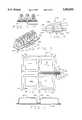
- FIG. 1is a top perspective view of a cushion embodying the invention
- FIG. 2is a bottom plan view of the cushion shown in FIG. 1;
- FIG. 3is a fragmentary sectional view taken along lines 3--3 of FIG. 2;
- FIG. 4is a fragmentary sectional view taken along lines 4--4 of FIG. 2.
- FIG. 5is a fragmentary perspective view of a method of interrupting fluid flow through the manifold and the channels.
- FIG. 6is a top plan view of a modification of the invention.
- FIG. 7is a sectional view taken along line 7--7 of FIG. 6.
- FIG. 1A designates a cellular cushion which is highly flexible and is designed for use on an underlying supporting surface, such as, the seat of a wheelchair or the seat of a conventional chair. Being cellular, the cushion A distributes the weight of its occupant generally uniformly over the entire area of the buttocks and thereby dissipates the pressures resulting from the supported weight at the ischia, that is, at the bony prominences of the buttocks. It further has the capacity to position and stabilize the user.
- the cushion Aincludes (FIG. 1) a base 2 and air cells 4 which project upwardly from the base 2. Both the base 2 and the air cells 4 are preferably molded or otherwise formed from highly flexible neoprene.
- the base 2is rectangular and the cells 4 are arranged on it in longitudinal rows and transverse rows, with each cell 4 occupying both a longitudinal row and a transverse row.
- the cells 4are further arranged in zones, typically, four zones r, s, t, and u. The zones r and s lie side by side at the front of the cushion A, whereas the zones t and u exist side by side at the rear of the cushion A.
- the right zones r and tare separated from the left zones s and u along a longitudinal axis x--x, whereas the front zones r and s are separated from the rear zones t and u along a transverse axis y--y. More or less zones and differing arrangements of those zones may be employed.
- the cells 4 of the zone rcommunicate with each other, so that all exist at the same internal pressure irrespective of how far they are depressed.
- the cells 4 of the zone s, the cells 4 of the zone t, and the cells 4 of the zone unormally do not communicate with the cells 4 of the zones s, t and u, or in other words the cells 4 of the zone r are normally isolated from the cells of the remaining zones s, t and u.
- the cells 4 of the zone sare normally isolated, as are the cells of the zones t and u.
- the cells 4 of each zone r, s, t and ucollectively enclose a separate compartment.
- fill tubes 20, 21, 22 and 23, respectivelyConnected to each of the zones r, s, t and u are fill tubes 20, 21, 22 and 23, respectively. These are flexible and tubular in cross-section. These terminate in close proximity to each other adjacent to, but outwardly of one edge of the cushion A. Preferably they come out from beneath the front edge of the cushion A so they are accessible to the wheelchair user.
- the outermost fill tubes 20 and 23are retained to the underside of the cushion A adjacent to the front edge by straps 20a and 23a which are secured to the cushion A, preferably by rivets 20b and 23b.
- the free ends of the tubes 20, 21, 22 and 23are connected to a manifold 24 to which is connected a fill nozzle 25 having a shut off valve 26 (FIG. 1).
- the fill tubes 20, 21, 22 and 23are all connected to the zones r, s, t and u through the underside of the cushion A. By passing beneath the cushion A, the fill tubes 20, 21, 22 and 23 provide access to the zones r, s, t and u for pressure monitoring devices. Also, there can be tubes or similar monitoring devices connected to each of the individual cells 4 through the underside of the cushion A so that a complete dynamic pressure profile of the patient can be taken at a remote location at any given point in time.
- the valves 30, as shown,comprise a base 31 having an upstanding lock post 32.
- a spring arm 33is connected to and overlies the base 31.
- the arm 32has a knife edge nose 34 which is designed to engage notches 35 on the post 32 to lock the arm 33 to the post 35 when in cut-off position.
- Cut-off members 36 and 37are on the base 31 and the arm 33 respectively. The cut-off members 36,37 are aligned, and when the nose 34 and lock notches 35 are engaged, move toward each other to force the tube sides together into linear sealing alignment to thereby block the tube and close off flow of air or other fluid through the fill tubes 20, 21, 22 and 23.
- the fill tubes 20, 21, 22 and 23pass through the arm 33 and the lock post 32 by means of ports 38, 38a, respectively. These manually operated valves can be replaced with electrically operated solenoid valves which would permit sequential operation. If no valves are desired, then the air flow can be sealed off by folding the tubes 20, 21, 22 and 23 back on themselves to cause them to buckle as shown in FIG. 5.
- the flexible tubular channels 20, 21, 22, 23 and manifold 24are bent back toward the cushion A to crimp the channels 20, 21, 22 and 23 and form linear seals therein.
- the manifold 24is held in its bent back position by the combination of the rigid nozzle 25 and a flexible retaining strap 27 which has one end fixed to the base 2 and the other end has a suitable fastening means 28, such as a snap fastener or a hook and loop fastener sold under the trademark VELCRO.
- a suitable fastening means 28such as a snap fastener or a hook and loop fastener sold under the trademark VELCRO.
- the valves 20, 21, 21 and 23are opened. This places the interiors of the cells 4 for the four zones r, s, t and u in communication through the mainfold 24. Air is pumped into the cushion through the valve 26. Since the cells 4 of the zones r, s, t and u are in communication through the manifold 24, all of the cells 4 are inflated. The cells 4 reach a state of equilibrium in a short time. Enough air is pumped into the cushion A to exceed the requirements for supporting the user. The valve 26 is then closed and the pump removed.
- the overinflated cushion Ais placed on the supporting surface upon which it is to rest when supporting the user, and that could be a wheelchair seat or the seat of a traditional chair.
- the userthen sits upon the cushion A in the location he expects to assume and slowly releases air from the filling valve 26 to immerse the user.
- the airis released, the user's buttocks sink deeper and deeper into the array of air cells 4, and they tend to envelope and assume the contour of the buttocks. Enough air is released to bring the region of the ischia to within about 1/2 inch of the base 2.
- all of the cells 4remain at essentially the same internal pressure, because they are all interconnected through the open manifold 24.
- the filling valve 26is closed.
- the userWhile immersed in the cells 4 of the cushion A, the user moves or is moved by others to the posture desired to be maintained for an extended period, and this causes a redistribution of air amongst the cells 4 of the several zones r, s, t and u.
- the cells 4 of the several zones r, s, t and ureach equilibrium, that is to say the flow between the zones r, s, t and u ceases.
- the individual valves 20, 21, 22 and 23are closed to prevent air from flowing between the zones r, s, t and u.
- the isolated zones r, s, t and uimpart stability to the cushion A, and this serves to maintain the user in the selected posture.
- the userattempts to assume a different posture, he will encounter greater resistance from cells 4 of one of more of the zones r, s, t and u, and they will urge the user back to the initial posture.
- the capacity to maintain a selected posture or to urge the user to such a postureis particularly useful with users who suffer from spinal deformities and for those whose muscles have atrophied.
- valve 26is opened and the individual cut-off valve 20, 21, 22 and 23 to the zone which is to be adjusted also is opened. Air can be added to or bled from the selected zone selectively without involving the other zones.
- An alternative constructionprovides for individual fill valves 40 on each of the zones r, s, t and u.
- the valves 40make it easier to test each quadrant or zone for leaks in the assembly process and also to separately fill or bleed each zone.
- the sectors r, s, t, and ucan be filled separately through the individual closure valves 40 or through selective opening and closing of the cut-off valves 20, 21, 22 and 23.
- FIGS. 6 and 7show a modification of the invention in which four independent cells 45 are positioned on the base 46 and have individual fill channels 47, 48, 49 and 50 which are connected to a manifold 51 having a fill nozzle 52.
- the channels 47, 48, 49 and 50may be on the top or the bottom of the base 46, but must be within the confines of the cushion and the ends should terminate in close proximity to each other outside one edge of the base 46.
- Each of the channels 47, 48, 49 and 50has a clamp or shut off valve 53 positioned between the edge of the cushion 46 and the manifold 51.
Landscapes
- Health & Medical Sciences (AREA)
- Life Sciences & Earth Sciences (AREA)
- Animal Behavior & Ethology (AREA)
- General Health & Medical Sciences (AREA)
- Public Health (AREA)
- Veterinary Medicine (AREA)
- Nursing (AREA)
- Mattresses And Other Support Structures For Chairs And Beds (AREA)
Abstract
Description
This is a continuation application of application Ser. No. 07/975,849, filed on Nov. 13, 1992 (now abandoned) which is a continuation-in-part of Ser. No. 07/778,450 filed Oct. 16, 1991, (now U.S. Pat. No. 5,163,196) which is a continuation-in-part of Ser. No. 07/607,902, filed Nov. 1, 1990 (now abandoned).
This invention relates in general to inflatable mattresses and cushions, and more particularly to an inflatable mattress or cushion having normally isolated zones and a series of valves for placing its normally isolated zones selectively in communication with each other and with atmosphere.
Those individuals who are confined to wheelchairs run the risk of tissue breakdown and the development of pressure sores, which are extremely dangerous and difficult to cure. Typically much of the individual's weight concentrates in the regions of the ischia, that is at the bony prominences of the buttocks, and unless frequent movement occurs, the flow of blood to the skin tissue in these regions decreases to the point that the tissue breaks down. Cushions which are especially designed for wheelchairs exist for reducing the concentration of weight in the region of the ischia, and these cushions generally seek to distribute the user's weight more uniformly over a larger area of the buttocks.
Cellular cushions provide the most uniform distribution of weight and thus provide the greatest protection from the occurrence of pressure sores. These cushions have an array of closely spaced air cells which project upwardly from a common base. Within the base the air cells communicate with each other, and thus all exist at the same internal pressure. Hence, each air cell exerts essentially the same restoring force against the buttocks, irrespective of the extent to which it is deflected. U.S. Pat. No. 4,541,136 shows a cellular cushion currently manufactured and sold by ROHO, Inc., of Belleville, Ill., for use on wheelchairs.
In a sense the typical cellular cushion provides a highly displaceable surface which tends to float the user. While this reduces the incidence of pressure sores, it detracts from the stability one usually associates with a seating surface. Most of those confined to wheelchairs have little trouble adjusting to the decrease in stability, but for those who have skeletal deformities, particularly in the region of the pelvis and thighs, and for those who lack adequate strength in their muscles, lesser stability can be a source of anxiety. A variation of the ROHO cellular cushion addresses this problem with totally isolated zones and also cells of varying height. By varying the pressure between zones, one can accommodate for skeletal deformities while still maintaining satisfactory protection against pressure sores. U.S. Pat. No. 4,698,864 shows a zoned cellular cushion with cells of varying height.
Typically, a zoned cellular cushion has a separate filling stem and valve for each of its zones. The user simply opens the valve of each stem and introduces air into the zone for that stem, usually with a hand pump, and then releases the air from the zones until the desired posture is achieved. In a more sophisticated arrangement, a hose kit connects a single pump to a manifold which in turn is connected to the several valves through separate hoses. These hoses are fitted with separate hose clamps so that the air from the pump may be directed to the cells of the individual zones independently, and likewise the air can be released from them independently, all by manipulating the clamps. The hoses of the hose kit lie externally of the cushion and may become entangled in components of a wheelchair. Furthermore, by reason of their remote location, the hose clamps are difficult to manipulate.
Even more traditional inflatable cushions derive advantages from zoning, that is from being divided into zones or compartments which can be isolated from each other to accommodate skeletal deformities.
Ser. No. 07/778,450 now U.S. Pat. No. 5,163,196, issued Nov. 17, 1992 describes a valve for a zoned inflatable cushion such that access to all of the zones is cut-off simultaneouly because the valve is in a flap which is part of the cushion base and all of the access channels run through the flap.
The present invention is an improvement on the prior cushions which utilize a series of hoses to inflate the cushion in that it positions the bodies of the hoses within the periphery of the cushion and gathers the ends of all of the hoses in close proximity adjacent to one edge so that they do not become entangled in the wheelchair and are readily accessible to the user. It also is an improvement on U.S. Pat. No. 5,163,196 in that the zones can be adjusted simultaneouly or selectively.
The present invention also resides in providing access to the cushion zones from beneath the cushion. A further advantage of the present invention is in providing access to the underside of the cushion and also to each cell of the cushion whereby pressure in each cell of the cushion can be monitored from a remote location.
This invention is equally appliable to inflatable mattresses, but will be described in connection with a wheelchair cushion.
These and other objects and advantages of the present invention will become apparent hereinafter.
In the accompanying drawings which form part of the specification and wherein like numerals and letters refer to like parts wherever they occur:
FIG. 1 is a top perspective view of a cushion embodying the invention;
FIG. 2 is a bottom plan view of the cushion shown in FIG. 1;
FIG. 3 is a fragmentary sectional view taken alonglines 3--3 of FIG. 2;
FIG. 4 is a fragmentary sectional view taken alonglines 4--4 of FIG. 2.
FIG. 5 is a fragmentary perspective view of a method of interrupting fluid flow through the manifold and the channels.
FIG. 6 is a top plan view of a modification of the invention; and
FIG. 7 is a sectional view taken alongline 7--7 of FIG. 6.
Referring now to the drawings (FIG. 1), A designates a cellular cushion which is highly flexible and is designed for use on an underlying supporting surface, such as, the seat of a wheelchair or the seat of a conventional chair. Being cellular, the cushion A distributes the weight of its occupant generally uniformly over the entire area of the buttocks and thereby dissipates the pressures resulting from the supported weight at the ischia, that is, at the bony prominences of the buttocks. It further has the capacity to position and stabilize the user.
The cushion A includes (FIG. 1) abase 2 andair cells 4 which project upwardly from thebase 2. Both thebase 2 and theair cells 4 are preferably molded or otherwise formed from highly flexible neoprene. Thebase 2 is rectangular and thecells 4 are arranged on it in longitudinal rows and transverse rows, with eachcell 4 occupying both a longitudinal row and a transverse row. Thecells 4 are further arranged in zones, typically, four zones r, s, t, and u. The zones r and s lie side by side at the front of the cushion A, whereas the zones t and u exist side by side at the rear of the cushion A. The right zones r and t are separated from the left zones s and u along a longitudinal axis x--x, whereas the front zones r and s are separated from the rear zones t and u along a transverse axis y--y. More or less zones and differing arrangements of those zones may be employed.
Within thebase 2, thecells 4 of the zone r communicate with each other, so that all exist at the same internal pressure irrespective of how far they are depressed. The same holds true with regard to thecells 4 of the zone s, thecells 4 of the zone t, and thecells 4 of the zone u. However, thecells 4 of the zone r normally do not communicate with thecells 4 of the zones s, t and u, or in other words thecells 4 of the zone r are normally isolated from the cells of the remaining zones s, t and u. Likewise thecells 4 of the zone s are normally isolated, as are the cells of the zones t and u. Thus, thecells 4 of each zone r, s, t and u collectively enclose a separate compartment.
Connected to each of the zones r, s, t and u arefill tubes outermost fill tubes tubes fill nozzle 25 having a shut off valve 26 (FIG. 1). Thefill tubes fill tubes individual cells 4 through the underside of the cushion A so that a complete dynamic pressure profile of the patient can be taken at a remote location at any given point in time.
Positioned on each of thetubes type hose valves 30. Thevalves 30, as shown, comprise a base 31 having anupstanding lock post 32. Aspring arm 33 is connected to and overlies thebase 31. Thearm 32 has aknife edge nose 34 which is designed to engagenotches 35 on thepost 32 to lock thearm 33 to thepost 35 when in cut-off position. Cut-off members base 31 and thearm 33 respectively. The cut-offmembers nose 34 and locknotches 35 are engaged, move toward each other to force the tube sides together into linear sealing alignment to thereby block the tube and close off flow of air or other fluid through thefill tubes fill tubes arm 33 and thelock post 32 by means ofports 38, 38a, respectively. These manually operated valves can be replaced with electrically operated solenoid valves which would permit sequential operation. If no valves are desired, then the air flow can be sealed off by folding thetubes
In the structure of FIG. 5, the flexibletubular channels manifold 24 are bent back toward the cushion A to crimp thechannels rigid nozzle 25 and aflexible retaining strap 27 which has one end fixed to thebase 2 and the other end has a suitable fastening means 28, such as a snap fastener or a hook and loop fastener sold under the trademark VELCRO. When using this type retainer, it is desirable to useindividual fill tubes 40 for each of the zones to provide for selective individual adjustment of the zones.
In order to prepare the cushion A for the user, thevalves cells 4 for the four zones r, s, t and u in communication through themainfold 24. Air is pumped into the cushion through thevalve 26. Since thecells 4 of the zones r, s, t and u are in communication through the manifold 24, all of thecells 4 are inflated. Thecells 4 reach a state of equilibrium in a short time. Enough air is pumped into the cushion A to exceed the requirements for supporting the user. Thevalve 26 is then closed and the pump removed.
Next the overinflated cushion A is placed on the supporting surface upon which it is to rest when supporting the user, and that could be a wheelchair seat or the seat of a traditional chair. The user then sits upon the cushion A in the location he expects to assume and slowly releases air from the fillingvalve 26 to immerse the user. As the air is released, the user's buttocks sink deeper and deeper into the array ofair cells 4, and they tend to envelope and assume the contour of the buttocks. Enough air is released to bring the region of the ischia to within about 1/2 inch of thebase 2. Of course, as the air flows out of the cushion A, all of thecells 4 remain at essentially the same internal pressure, because they are all interconnected through theopen manifold 24. When the user achieves the desired immersion, the fillingvalve 26 is closed.
While immersed in thecells 4 of the cushion A, the user moves or is moved by others to the posture desired to be maintained for an extended period, and this causes a redistribution of air amongst thecells 4 of the several zones r, s, t and u. In time, thecells 4 of the several zones r, s, t and u reach equilibrium, that is to say the flow between the zones r, s, t and u ceases. At this time, theindividual valves
The isolated zones r, s, t and u impart stability to the cushion A, and this serves to maintain the user in the selected posture. Thus, if the user attempts to assume a different posture, he will encounter greater resistance fromcells 4 of one of more of the zones r, s, t and u, and they will urge the user back to the initial posture. The capacity to maintain a selected posture or to urge the user to such a posture is particularly useful with users who suffer from spinal deformities and for those whose muscles have atrophied.
To further adjust the position of the user on the cushion, thevalve 26 is opened and the individual cut-offvalve
An alternative construction provides forindividual fill valves 40 on each of the zones r, s, t and u. Thevalves 40 make it easier to test each quadrant or zone for leaks in the assembly process and also to separately fill or bleed each zone.
Thus, the sectors r, s, t, and u can be filled separately through theindividual closure valves 40 or through selective opening and closing of the cut-offvalves
FIGS. 6 and 7 show a modification of the invention in which fourindependent cells 45 are positioned on thebase 46 and haveindividual fill channels fill nozzle 52. Thechannels base 46, but must be within the confines of the cushion and the ends should terminate in close proximity to each other outside one edge of thebase 46.
Each of thechannels valve 53 positioned between the edge of thecushion 46 and the manifold 51.
Ifclamps 53 are not used, the manifold 51 is bent back on itself and locked down to the base 46 to close off and seal thetubes independent fill tubes 54 may be positioned in each of thecells 45 of the cushion.
This invention is intended to cover all changes and modifications of the example of the invention herein chosen for purposes of the disclosure which do not constitute departures from the spirit and scope of the invention.
Claims (10)
1. A cellular cushion comprising a flexible non-rigid base throughout the cellular area of the cushion, said flexible base having front, rear and side edges, a plurality of flexible and hollow air containing cells attached to and projecting away from the flexible base, the cells being organized into zones, with the interiors of the cells for each zone within the region of the zone being in communication through the flexible base, but not with the air cells of the other zones, a manifold located at one edge of the flexible base and extending outwardly from the flexible base, first and second separate and independent air passages connected to each zone, said first air passage for each zone defining a fixed channel extending between at least one cell of its zone and the manifold, the channels being connected to the cushion cells through the flexible base of the cushion and the channels extending along the underside of the flexible base to the manifold, whereby the cells of the different zones communicate only through the manifold, and means for selectively blocking the channels independently of the manifold so that the cells of the different zones do not communicate and the air pressure of each zone can be adjusted independently, said second air passage for each zone being separate from and independent of the first air passage and the manifold to allow adding and bleeding air only from the zone to which it is connected.
2. The cushion of claim 1 wherein the channels are positioned within the periphery of the cushion until they come together to join the manifold.
3. The cushion of claim 1 wherein the channels are flexible and tubular in shape and the air blocking means are clamps which compress the flexible tubes together so that the interiors of the tube walls are flattened and form a linear seal across the tube.
4. A cellular cushion comprising a flexible non-rigid base throughout the cellular area of the cushion, said flexible base having front, rear and side edges, a plurality of flexible and hollow fluid containing cells attached to and projecting away from the flexible base, the cells being organized into zones, with the interiors of the cells for each zone within the region of the zone being in communication through the flexible base, but not with the air cells of the other zones, first and second separate and independent air passages connected to each zone, said first air passage for each zone defining a fixed channel extending from the bottom of at least one cell of its zone along the underside of the cushion and past an edge of the cushion, the channels having free ends which are connected to a manifold positioned past the cushion edge and the channels are flexible and tubular in shape, whereby the cells of the different zones do not communicate with each other and access to the individual cells is had to monitor the fluid pressure in the zones remotely from the cells, said second air passage for each zone being separate from and independent of the first air passage and the manifold to allow adding and bleeding air only from the zone to which it is connected.
5. The cushion of claim 4 including means for retaining the tubular members in juxtaposed position folded back upon themselves to shut off flow through all of the channels simultaneously.
6. The cushion of claim 4 wherein the channels include means for blocking the channels selectively and in unison.
7. The cushion of claim 4 wherein the portions of the channels which extend past the cushion edges are tubular and flexible and including means for squeezing the tube walls together into linear engagement to seal the tubes and stop fluid flow therethrough.
8. The cushion of claim 4 herein the channels which extend past the cushion edges are in close juxtaposition and are flexible and tubular and including means for squeezing the tube walls together into linear engagement to seal the tubes and stop fluid flow therethrough.
9. A cellular cushion comprising a flexible non-rigid base throughout the cellular area of the cushion, said flexible base having front, rear and side edges, a plurality of flexible and hollow fluid containing cells attached to and projecting away from the flexible base, first and second separate and independent air passages connected to each cell, said first air passage for each cell defining a fixed separate fill channel for each cell, with each channel extending from the underside of the cell along the flexible cushion base past an edge of the cushion, the channels having free ends which are connected to a manifold positioned past the cushion edge and the channels are flexible and tubular in shape, whereby the cells are independent and do not communicate with each other and access to the individual cells is had to change the fluid pressure in the cells remotely from the cells, said second air passage for each cell being separate from and independent of the first air passage and the manifold to allow adding and bleeding air only from the cell to which it is connected.
10. The cushion of claim 9 including means for retaining the tubular members in juxtaposed position folded back upon themselves to shut off flow through all of the channels simultaneouly.
Priority Applications (1)
| Application Number | Priority Date | Filing Date | Title |
|---|---|---|---|
| US08/374,836US5502855A (en) | 1990-11-01 | 1995-01-19 | Zoned cellular cushion |
Applications Claiming Priority (4)
| Application Number | Priority Date | Filing Date | Title |
|---|---|---|---|
| US60790290A | 1990-11-01 | 1990-11-01 | |
| US07/778,450US5163196A (en) | 1990-11-01 | 1991-10-16 | Zoned cellular cushion with flexible flaps containing inflating manifold |
| US97584992A | 1992-11-13 | 1992-11-13 | |
| US08/374,836US5502855A (en) | 1990-11-01 | 1995-01-19 | Zoned cellular cushion |
Related Parent Applications (1)
| Application Number | Title | Priority Date | Filing Date |
|---|---|---|---|
| US97584992AContinuation | 1990-11-01 | 1992-11-13 |
Publications (1)
| Publication Number | Publication Date |
|---|---|
| US5502855Atrue US5502855A (en) | 1996-04-02 |
Family
ID=27416983
Family Applications (1)
| Application Number | Title | Priority Date | Filing Date |
|---|---|---|---|
| US08/374,836Expired - LifetimeUS5502855A (en) | 1990-11-01 | 1995-01-19 | Zoned cellular cushion |
Country Status (1)
| Country | Link |
|---|---|
| US (1) | US5502855A (en) |
Cited By (70)
| Publication number | Priority date | Publication date | Assignee | Title |
|---|---|---|---|---|
| US5678265A (en)* | 1996-01-11 | 1997-10-21 | Meyer; Kenneth G. | Inflatable cushion |
| WO1998004170A1 (en) | 1996-07-31 | 1998-02-05 | Graebe Robert H | Wraparound orthotic base cushion |
| WO1998029010A1 (en) | 1997-01-02 | 1998-07-09 | Graebe Robert H | Motorcycle seat cushion |
| US6321404B1 (en) | 1998-07-15 | 2001-11-27 | Jen Hsiu Tsai | Built-up air cushion |
| WO2001091617A1 (en)* | 2000-06-01 | 2001-12-06 | Crown Therapeutics, Inc. | Moisture drying mattress with separate zone controls |
| US6425399B1 (en) | 1997-08-18 | 2002-07-30 | William Hoster, Jr. | Emergency inflatable spinal support device |
| WO2002065004A1 (en)* | 2001-01-18 | 2002-08-22 | Roho, Inc. | Valve for zoned cellular cushion |
| US6519797B1 (en)* | 1999-08-10 | 2003-02-18 | Dynamic Contours Llc | Self adjusting, contouring cushioning system |
| US6532613B2 (en)* | 2001-06-07 | 2003-03-18 | Berry, Iv Russell M. | Three dimensional star shaped pliable chair |
| US6550085B2 (en)* | 1997-06-23 | 2003-04-22 | Georges M. Roux | Support for expansible cells |
| US6560803B2 (en) | 2000-09-05 | 2003-05-13 | Levy Zur | Pressure relief pneumatic area support device and system |
| US20030208849A1 (en)* | 1999-04-20 | 2003-11-13 | Wilkinson John W. | Inflatable cushioning device with manifold system |
| US6687936B2 (en) | 2001-01-18 | 2004-02-10 | Roho, Inc. | Valve for zoned cellular cushion |
| US20040237201A1 (en)* | 2003-05-29 | 2004-12-02 | Fraser Kevin Gerard | Methods and apparatus for fabricating cellular cushions |
| US20050116526A1 (en)* | 2003-10-23 | 2005-06-02 | Herman Miller, Inc. | Pixelated support structures and elements |
| US20050120483A1 (en)* | 2003-12-05 | 2005-06-09 | Clapper Dennis L. | Heat diffusing cushion or mattress |
| US20050125905A1 (en)* | 1999-04-20 | 2005-06-16 | John Wilkinson | Inflatable cushioning device with manifold system |
| US6941602B2 (en) | 1999-08-10 | 2005-09-13 | Dynamic Contours, Llc | Self adjusting, contouring cushioning system |
| US20060117486A1 (en)* | 2004-12-03 | 2006-06-08 | Clark Ted D | Mattress repair apparatus |
| US20070056112A1 (en)* | 2005-09-09 | 2007-03-15 | Graebe Robert H | Zoned cellular cushion with fail safe inflation zones |
| US20070262634A1 (en)* | 2006-05-12 | 2007-11-15 | Brill Ryan S | Suspended pixelated seating structure |
| US7392557B1 (en)* | 2005-03-31 | 2008-07-01 | Aquila Corporation Of Wisconsin | Cushion with group of mutually inflatable and deflatable cells and system for selectively isolating one or more cells from the group for independent inflation and deflation |
| US7455355B1 (en) | 2007-01-19 | 2008-11-25 | Aquilla Corporation Of Wisconsin | User adjustable motorcycle seat cushion with independently inflatable and deflatable ischial support cell and gluteous support cell |
| USD587914S1 (en) | 2008-01-28 | 2009-03-10 | Herman Miller, Inc. | Chair |
| USD597771S1 (en) | 2008-01-28 | 2009-08-11 | Herman Miller, Inc. | Backrest |
| US7604292B1 (en) | 2005-11-03 | 2009-10-20 | Reading Randall C | Vehicle seat with dynamic cushion and lumbar support |
| US20090302662A1 (en)* | 2008-06-04 | 2009-12-10 | Groelsma John C | Suspension seating |
| US20100021685A1 (en)* | 2008-07-25 | 2010-01-28 | Brill Ryan S | Multi-layered support structure |
| US20100089458A1 (en)* | 2004-10-08 | 2010-04-15 | Chaffee Robert B | Methods and apparatus for controlling air in inflatable devices |
| USD617131S1 (en) | 2010-01-05 | 2010-06-08 | Roho, Inc. | Seat cushion |
| US20100139003A1 (en)* | 2006-12-09 | 2010-06-10 | Smart Surfaces Inc. | Device for supporting a user's body |
| US20100146709A1 (en)* | 2008-12-17 | 2010-06-17 | Stryker Corporation | Patient support |
| USD643665S1 (en) | 2010-01-20 | 2011-08-23 | Roho, Inc. | Inflatable seat cushion |
| USD645285S1 (en) | 2010-01-20 | 2011-09-20 | Roho, Inc. | Inflatable seat cushion |
| USD645284S1 (en) | 2010-01-20 | 2011-09-20 | Roho, Inc. | Inflatable seat cushion |
| USD646101S1 (en) | 2010-01-20 | 2011-10-04 | Roho, Inc. | Inflatable seat cushion |
| USD646100S1 (en) | 2010-02-10 | 2011-10-04 | Roho, Inc. | Inflatable cushion insert |
| USD647345S1 (en) | 2010-01-20 | 2011-10-25 | Roho, Inc. | Inflatable seat cushion |
| USD647343S1 (en) | 2010-01-20 | 2011-10-25 | Roho, Inc. | Inflatable seat cushion |
| USD647344S1 (en) | 2010-01-20 | 2011-10-25 | Roho, Inc. | Inflatable seat cushion |
| USD647346S1 (en) | 2010-02-10 | 2011-10-25 | Roho, Inc. | Inflatable cushion insert |
| USD647348S1 (en) | 2010-02-10 | 2011-10-25 | Roho, Inc. | Inflatable cushion insert |
| USD647349S1 (en) | 2010-02-10 | 2011-10-25 | Roho, Inc. | Inflatable cushion insert |
| USD647347S1 (en) | 2010-02-10 | 2011-10-25 | Roho, Inc. | Inflatable cushion insert |
| USD648169S1 (en) | 2010-12-13 | 2011-11-08 | Roho, Inc. | Composite seat cushion |
| USD648168S1 (en) | 2010-01-20 | 2011-11-08 | Roho, Inc. | Inflatable seat cushion |
| USD650214S1 (en) | 2010-02-10 | 2011-12-13 | Roho, Inc. | Inflatable cushion insert |
| US20130055504A1 (en)* | 2011-09-06 | 2013-03-07 | Douglas E. Peash | Pneumatic lifting cushion |
| US8397326B2 (en) | 2010-02-05 | 2013-03-19 | Stryker Corporation | Patient/invalid handling support |
| US8419133B2 (en) | 2007-01-29 | 2013-04-16 | Herman Miller, Inc. | Seating structure with independently adjustable back |
| US8555441B2 (en) | 2010-04-14 | 2013-10-15 | Star Cushion Products, Inc. | Therapeutic mattress system and methods of fabricating same |
| US8584286B2 (en) | 2010-04-27 | 2013-11-19 | Ec Service Inc. | Systems and methods for providing a self deflating cushion |
| US20140345058A1 (en)* | 2013-05-21 | 2014-11-27 | SEC Medical Development, Inc. | Pressure Monitoring and Management Cushion System And Method Of Use |
| US8910331B2 (en) | 2012-07-18 | 2014-12-16 | Shanghai Chuangshi Industry (Group) Co., Ltd. | Cushion for preventing pressure sore |
| US9066599B1 (en) | 2014-02-17 | 2015-06-30 | Justin James Waggoner | Mattress restoration assembly and method of use |
| US9468307B2 (en) | 2012-09-05 | 2016-10-18 | Stryker Corporation | Inflatable mattress and control methods |
| USD798634S1 (en) | 2016-08-26 | 2017-10-03 | Airhawk International, Llc | Air cushion |
| US9782312B2 (en) | 2013-09-05 | 2017-10-10 | Stryker Corporation | Patient support |
| US9820904B2 (en) | 2011-07-13 | 2017-11-21 | Stryker Corporation | Patient/invalid handling support |
| RU188899U1 (en)* | 2018-06-22 | 2019-04-29 | Евгений Владимирович Суров | Orthopedic adjustable pillow |
| US20200070702A1 (en)* | 2018-08-28 | 2020-03-05 | The Boeing Company | Shape adapting system and method for a cushion assembly |
| US10646049B2 (en) | 2017-10-31 | 2020-05-12 | Airhawk International, Llc | Seat cushion |
| USD898447S1 (en)* | 2020-01-31 | 2020-10-13 | Higher Auto Accessories Co., Ltd | Cushion |
| US20210205160A1 (en)* | 2019-09-06 | 2021-07-08 | Shanghai Chuangshi Industry Group Co., Ltd. | Airbag cushion assembly, intelligent pressure sore prevention cushion, and monitoring system |
| US20220361692A1 (en)* | 2021-05-13 | 2022-11-17 | Bussert Medical, Inc | Therapeutic cushions and systems for using the same |
| US11540959B1 (en) | 2019-07-11 | 2023-01-03 | Steven Paul Kohlman | Therapy seat cushion with interspersed selectively inflatable load bearing cells and off loading cushioning cells |
| USD982356S1 (en)* | 2020-11-20 | 2023-04-04 | Acutens, Inc. | Neck cushion |
| USD985969S1 (en)* | 2021-09-16 | 2023-05-16 | Sunrise Medical (Us) Llc | Inflatable seat cushion |
| USD986637S1 (en)* | 2020-11-20 | 2023-05-23 | Acutens, Inc. | Neck cushion |
| WO2023132944A1 (en)* | 2022-01-07 | 2023-07-13 | Permobil, Inc. | Multi-position airflow control assembly for an air cushion |
Citations (14)
| Publication number | Priority date | Publication date | Assignee | Title |
|---|---|---|---|---|
| US1970803A (en)* | 1932-10-03 | 1934-08-21 | Johnson John Herbert | Method of making an inflatable rubber structure |
| US2434641A (en)* | 1946-02-20 | 1948-01-20 | Henry L Burns | Resilient seat cushion |
| US2575764A (en)* | 1947-04-10 | 1951-11-20 | Hans G Morner | Air-filled upholstery and method of manufacture |
| US2731652A (en)* | 1951-06-01 | 1956-01-24 | Edward P Bishop | Air mattress |
| US3192540A (en)* | 1962-01-22 | 1965-07-06 | Richard E Swank | Adjustable pneumatic support |
| US3192541A (en)* | 1962-03-19 | 1965-07-06 | Boyd S Moore | Contourable pneumatic cushions |
| US3303518A (en)* | 1962-03-05 | 1967-02-14 | Ingram George | Inflatable mattresses, pillows and cushions |
| DE1951476A1 (en)* | 1969-10-13 | 1971-07-08 | Meyer Geb Urbank | Lying mat |
| US3984886A (en)* | 1975-08-20 | 1976-10-12 | Keeton J Herbert | Fluid-filled cushioning assemblies |
| US4267611A (en)* | 1979-03-08 | 1981-05-19 | Arnold Agulnick | Inflatable massaging and cooling mattress |
| US4541136A (en)* | 1983-09-01 | 1985-09-17 | Graebe Robert H | Multicell cushion |
| US4662012A (en)* | 1983-12-07 | 1987-05-05 | Torbet Philip A | Bed utilizing an air mattress |
| US4698864A (en)* | 1985-11-25 | 1987-10-13 | Graebe Robert H | Cellular cushion |
| US4864671A (en)* | 1988-03-28 | 1989-09-12 | Decubitus, Inc. | Controllably inflatable cushion |
- 1995
- 1995-01-19USUS08/374,836patent/US5502855A/ennot_activeExpired - Lifetime
Patent Citations (14)
| Publication number | Priority date | Publication date | Assignee | Title |
|---|---|---|---|---|
| US1970803A (en)* | 1932-10-03 | 1934-08-21 | Johnson John Herbert | Method of making an inflatable rubber structure |
| US2434641A (en)* | 1946-02-20 | 1948-01-20 | Henry L Burns | Resilient seat cushion |
| US2575764A (en)* | 1947-04-10 | 1951-11-20 | Hans G Morner | Air-filled upholstery and method of manufacture |
| US2731652A (en)* | 1951-06-01 | 1956-01-24 | Edward P Bishop | Air mattress |
| US3192540A (en)* | 1962-01-22 | 1965-07-06 | Richard E Swank | Adjustable pneumatic support |
| US3303518A (en)* | 1962-03-05 | 1967-02-14 | Ingram George | Inflatable mattresses, pillows and cushions |
| US3192541A (en)* | 1962-03-19 | 1965-07-06 | Boyd S Moore | Contourable pneumatic cushions |
| DE1951476A1 (en)* | 1969-10-13 | 1971-07-08 | Meyer Geb Urbank | Lying mat |
| US3984886A (en)* | 1975-08-20 | 1976-10-12 | Keeton J Herbert | Fluid-filled cushioning assemblies |
| US4267611A (en)* | 1979-03-08 | 1981-05-19 | Arnold Agulnick | Inflatable massaging and cooling mattress |
| US4541136A (en)* | 1983-09-01 | 1985-09-17 | Graebe Robert H | Multicell cushion |
| US4662012A (en)* | 1983-12-07 | 1987-05-05 | Torbet Philip A | Bed utilizing an air mattress |
| US4698864A (en)* | 1985-11-25 | 1987-10-13 | Graebe Robert H | Cellular cushion |
| US4864671A (en)* | 1988-03-28 | 1989-09-12 | Decubitus, Inc. | Controllably inflatable cushion |
Non-Patent Citations (2)
| Title |
|---|
| Roho Inc. brochure; The Challenge: Pelvic and Thigh Positioning, date unknown.* |
| Roho Inc. brochure; The Roho Quadtro Cushion, date unknown.* |
Cited By (107)
| Publication number | Priority date | Publication date | Assignee | Title |
|---|---|---|---|---|
| US5678265A (en)* | 1996-01-11 | 1997-10-21 | Meyer; Kenneth G. | Inflatable cushion |
| WO1998004170A1 (en) | 1996-07-31 | 1998-02-05 | Graebe Robert H | Wraparound orthotic base cushion |
| US6018832A (en)* | 1996-07-31 | 2000-02-01 | Graebe; Robert H. | Wraparound orthotic base composite adjustable cushion using same and method of measuring fit of the adjusted cushion to the user's shape |
| US6161238A (en)* | 1996-07-31 | 2000-12-19 | Graebe; Robert H. | Wraparound orthotic base, composite adjustable cushion using same and method of measuring fit of the adjusted cushion to the user's shape |
| WO1998029010A1 (en) | 1997-01-02 | 1998-07-09 | Graebe Robert H | Motorcycle seat cushion |
| US6550085B2 (en)* | 1997-06-23 | 2003-04-22 | Georges M. Roux | Support for expansible cells |
| US6684430B2 (en) | 1997-06-23 | 2004-02-03 | Georges M. Roux | Support for expansible cells |
| US6425399B1 (en) | 1997-08-18 | 2002-07-30 | William Hoster, Jr. | Emergency inflatable spinal support device |
| US6321404B1 (en) | 1998-07-15 | 2001-11-27 | Jen Hsiu Tsai | Built-up air cushion |
| US20030208849A1 (en)* | 1999-04-20 | 2003-11-13 | Wilkinson John W. | Inflatable cushioning device with manifold system |
| US8122545B2 (en) | 1999-04-20 | 2012-02-28 | M.P.L. Limited | Inflatable cushioning device with manifold system |
| USRE44584E1 (en) | 1999-04-20 | 2013-11-12 | M.P.L. Limited | Inflatable cushioning device with manifold system |
| US20050125905A1 (en)* | 1999-04-20 | 2005-06-16 | John Wilkinson | Inflatable cushioning device with manifold system |
| US10357114B2 (en) | 1999-04-20 | 2019-07-23 | Wcw, Inc. | Inflatable cushioning device with manifold system |
| US6519797B1 (en)* | 1999-08-10 | 2003-02-18 | Dynamic Contours Llc | Self adjusting, contouring cushioning system |
| US6941602B2 (en) | 1999-08-10 | 2005-09-13 | Dynamic Contours, Llc | Self adjusting, contouring cushioning system |
| US6487739B1 (en)* | 2000-06-01 | 2002-12-03 | Crown Therapeutics, Inc. | Moisture drying mattress with separate zone controls |
| WO2001091617A1 (en)* | 2000-06-01 | 2001-12-06 | Crown Therapeutics, Inc. | Moisture drying mattress with separate zone controls |
| US6687937B2 (en) | 2000-06-01 | 2004-02-10 | Crown Therapeutics, Inc. | Moisture drying mattress with separate zone controls |
| US6560803B2 (en) | 2000-09-05 | 2003-05-13 | Levy Zur | Pressure relief pneumatic area support device and system |
| WO2002065004A1 (en)* | 2001-01-18 | 2002-08-22 | Roho, Inc. | Valve for zoned cellular cushion |
| US6564410B2 (en) | 2001-01-18 | 2003-05-20 | Roho, Inc. | Valve for zoned cellular cushion |
| EP1352189A4 (en)* | 2001-01-18 | 2006-09-13 | Roho Inc | Valve for zoned cellular cushion |
| US6687936B2 (en) | 2001-01-18 | 2004-02-10 | Roho, Inc. | Valve for zoned cellular cushion |
| US6532613B2 (en)* | 2001-06-07 | 2003-03-18 | Berry, Iv Russell M. | Three dimensional star shaped pliable chair |
| US7434282B2 (en)* | 2003-05-29 | 2008-10-14 | Star Cushion Products, Inc. | Cellular cushions and methods of fabricating |
| US20040237201A1 (en)* | 2003-05-29 | 2004-12-02 | Fraser Kevin Gerard | Methods and apparatus for fabricating cellular cushions |
| US20070246873A1 (en)* | 2003-10-23 | 2007-10-25 | Vanderiet Douglas M | Multilayer load bearing structure |
| US20050116526A1 (en)* | 2003-10-23 | 2005-06-02 | Herman Miller, Inc. | Pixelated support structures and elements |
| US7931257B2 (en) | 2003-10-23 | 2011-04-26 | Herman Miller, Inc. | Multilayer load bearing structure |
| US20050120483A1 (en)* | 2003-12-05 | 2005-06-09 | Clapper Dennis L. | Heat diffusing cushion or mattress |
| US20100089458A1 (en)* | 2004-10-08 | 2010-04-15 | Chaffee Robert B | Methods and apparatus for controlling air in inflatable devices |
| EP2181625A3 (en)* | 2004-10-08 | 2010-12-22 | Robert B. Chaffee | cover for an inflatable device |
| US20060117486A1 (en)* | 2004-12-03 | 2006-06-08 | Clark Ted D | Mattress repair apparatus |
| US7392557B1 (en)* | 2005-03-31 | 2008-07-01 | Aquila Corporation Of Wisconsin | Cushion with group of mutually inflatable and deflatable cells and system for selectively isolating one or more cells from the group for independent inflation and deflation |
| US20070056112A1 (en)* | 2005-09-09 | 2007-03-15 | Graebe Robert H | Zoned cellular cushion with fail safe inflation zones |
| US7604292B1 (en) | 2005-11-03 | 2009-10-20 | Reading Randall C | Vehicle seat with dynamic cushion and lumbar support |
| US8186761B2 (en) | 2006-05-12 | 2012-05-29 | Herman Miller, Inc. | Suspended pixelated seating structure |
| US7740321B2 (en) | 2006-05-12 | 2010-06-22 | Herman Miller, Inc. | Suspended pixelated seating structure |
| US20100253128A1 (en)* | 2006-05-12 | 2010-10-07 | Herman Miller, Inc. | Suspended pixelated seating structure |
| US20070262634A1 (en)* | 2006-05-12 | 2007-11-15 | Brill Ryan S | Suspended pixelated seating structure |
| US20100139003A1 (en)* | 2006-12-09 | 2010-06-10 | Smart Surfaces Inc. | Device for supporting a user's body |
| US8572783B2 (en) | 2006-12-09 | 2013-11-05 | Theratorr Medical, Inc. | Device for supporting a user's body |
| US7455355B1 (en) | 2007-01-19 | 2008-11-25 | Aquilla Corporation Of Wisconsin | User adjustable motorcycle seat cushion with independently inflatable and deflatable ischial support cell and gluteous support cell |
| US8419133B2 (en) | 2007-01-29 | 2013-04-16 | Herman Miller, Inc. | Seating structure with independently adjustable back |
| US8469454B2 (en) | 2007-01-29 | 2013-06-25 | Herman Miller, Inc. | Back construction |
| USD587914S1 (en) | 2008-01-28 | 2009-03-10 | Herman Miller, Inc. | Chair |
| USD597771S1 (en) | 2008-01-28 | 2009-08-11 | Herman Miller, Inc. | Backrest |
| US20090302662A1 (en)* | 2008-06-04 | 2009-12-10 | Groelsma John C | Suspension seating |
| US8128175B2 (en) | 2008-06-04 | 2012-03-06 | Herman Miller, Inc. | Suspension seating |
| US9629467B2 (en) | 2008-07-25 | 2017-04-25 | Herman Miller, Inc. | Method for manufacturing a multi-layered support structure |
| US8691370B2 (en) | 2008-07-25 | 2014-04-08 | Herman Miller, Inc. | Multi-layered support structure |
| US20100021685A1 (en)* | 2008-07-25 | 2010-01-28 | Brill Ryan S | Multi-layered support structure |
| US8910334B2 (en) | 2008-12-17 | 2014-12-16 | Stryker Corporation | Patient support |
| US20100175196A1 (en)* | 2008-12-17 | 2010-07-15 | Patrick Lafleche | Patient support |
| US20100146709A1 (en)* | 2008-12-17 | 2010-06-17 | Stryker Corporation | Patient support |
| USD617131S1 (en) | 2010-01-05 | 2010-06-08 | Roho, Inc. | Seat cushion |
| USD647343S1 (en) | 2010-01-20 | 2011-10-25 | Roho, Inc. | Inflatable seat cushion |
| USD647344S1 (en) | 2010-01-20 | 2011-10-25 | Roho, Inc. | Inflatable seat cushion |
| USD648168S1 (en) | 2010-01-20 | 2011-11-08 | Roho, Inc. | Inflatable seat cushion |
| USD643665S1 (en) | 2010-01-20 | 2011-08-23 | Roho, Inc. | Inflatable seat cushion |
| USD645285S1 (en) | 2010-01-20 | 2011-09-20 | Roho, Inc. | Inflatable seat cushion |
| USD645284S1 (en) | 2010-01-20 | 2011-09-20 | Roho, Inc. | Inflatable seat cushion |
| USD646101S1 (en) | 2010-01-20 | 2011-10-04 | Roho, Inc. | Inflatable seat cushion |
| USD647345S1 (en) | 2010-01-20 | 2011-10-25 | Roho, Inc. | Inflatable seat cushion |
| US8397326B2 (en) | 2010-02-05 | 2013-03-19 | Stryker Corporation | Patient/invalid handling support |
| US8832885B2 (en) | 2010-02-05 | 2014-09-16 | Stryker Corporation | Patient/invalid handling support |
| US8856992B2 (en) | 2010-02-05 | 2014-10-14 | Stryker Corporation | Patient/invalid handling support |
| USD647349S1 (en) | 2010-02-10 | 2011-10-25 | Roho, Inc. | Inflatable cushion insert |
| USD650214S1 (en) | 2010-02-10 | 2011-12-13 | Roho, Inc. | Inflatable cushion insert |
| USD646100S1 (en) | 2010-02-10 | 2011-10-04 | Roho, Inc. | Inflatable cushion insert |
| USD647348S1 (en) | 2010-02-10 | 2011-10-25 | Roho, Inc. | Inflatable cushion insert |
| USD647346S1 (en) | 2010-02-10 | 2011-10-25 | Roho, Inc. | Inflatable cushion insert |
| USD647347S1 (en) | 2010-02-10 | 2011-10-25 | Roho, Inc. | Inflatable cushion insert |
| US8555441B2 (en) | 2010-04-14 | 2013-10-15 | Star Cushion Products, Inc. | Therapeutic mattress system and methods of fabricating same |
| US8584286B2 (en) | 2010-04-27 | 2013-11-19 | Ec Service Inc. | Systems and methods for providing a self deflating cushion |
| USD648169S1 (en) | 2010-12-13 | 2011-11-08 | Roho, Inc. | Composite seat cushion |
| US12213926B2 (en) | 2011-07-13 | 2025-02-04 | Stryker Corporation | Patient/invalid handling support |
| US12329700B2 (en) | 2011-07-13 | 2025-06-17 | Stryker Corporation | Patient/invalid handling support with immersion sensing |
| US9820904B2 (en) | 2011-07-13 | 2017-11-21 | Stryker Corporation | Patient/invalid handling support |
| US10987265B2 (en) | 2011-07-13 | 2021-04-27 | Stryker Corporation | Patient/invalid handling support |
| US20130055504A1 (en)* | 2011-09-06 | 2013-03-07 | Douglas E. Peash | Pneumatic lifting cushion |
| US8910331B2 (en) | 2012-07-18 | 2014-12-16 | Shanghai Chuangshi Industry (Group) Co., Ltd. | Cushion for preventing pressure sore |
| US9468307B2 (en) | 2012-09-05 | 2016-10-18 | Stryker Corporation | Inflatable mattress and control methods |
| US12023287B2 (en) | 2012-09-05 | 2024-07-02 | Stryker Corporation | Inflatable mattress and control methods |
| US10682273B2 (en) | 2012-09-05 | 2020-06-16 | Stryker Corporation | Inflatable mattress and control methods |
| US11413202B2 (en) | 2012-09-05 | 2022-08-16 | Stryker Corporation | Inflatable mattress and control methods |
| US20140345058A1 (en)* | 2013-05-21 | 2014-11-27 | SEC Medical Development, Inc. | Pressure Monitoring and Management Cushion System And Method Of Use |
| US9782312B2 (en) | 2013-09-05 | 2017-10-10 | Stryker Corporation | Patient support |
| US9066599B1 (en) | 2014-02-17 | 2015-06-30 | Justin James Waggoner | Mattress restoration assembly and method of use |
| USD798634S1 (en) | 2016-08-26 | 2017-10-03 | Airhawk International, Llc | Air cushion |
| US10646049B2 (en) | 2017-10-31 | 2020-05-12 | Airhawk International, Llc | Seat cushion |
| RU188899U1 (en)* | 2018-06-22 | 2019-04-29 | Евгений Владимирович Суров | Orthopedic adjustable pillow |
| US10850655B2 (en)* | 2018-08-28 | 2020-12-01 | The Boeing Company | Shape adapting system and method for a cushion assembly |
| US20200070702A1 (en)* | 2018-08-28 | 2020-03-05 | The Boeing Company | Shape adapting system and method for a cushion assembly |
| US11540959B1 (en) | 2019-07-11 | 2023-01-03 | Steven Paul Kohlman | Therapy seat cushion with interspersed selectively inflatable load bearing cells and off loading cushioning cells |
| US20210205160A1 (en)* | 2019-09-06 | 2021-07-08 | Shanghai Chuangshi Industry Group Co., Ltd. | Airbag cushion assembly, intelligent pressure sore prevention cushion, and monitoring system |
| US11793700B2 (en)* | 2019-09-06 | 2023-10-24 | Shanghai Chuangshi Industry Group Co., Ltd. | Airbag cushion assembly, intelligent pressure sore prevention cushion, and monitoring system |
| USD898447S1 (en)* | 2020-01-31 | 2020-10-13 | Higher Auto Accessories Co., Ltd | Cushion |
| USD986637S1 (en)* | 2020-11-20 | 2023-05-23 | Acutens, Inc. | Neck cushion |
| USD982356S1 (en)* | 2020-11-20 | 2023-04-04 | Acutens, Inc. | Neck cushion |
| US20220361692A1 (en)* | 2021-05-13 | 2022-11-17 | Bussert Medical, Inc | Therapeutic cushions and systems for using the same |
| US12178347B2 (en)* | 2021-05-13 | 2024-12-31 | Bussert Medical, Inc. | Therapeutic cushions and systems for using the same |
| USD985969S1 (en)* | 2021-09-16 | 2023-05-16 | Sunrise Medical (Us) Llc | Inflatable seat cushion |
| US12178767B2 (en) | 2022-01-07 | 2024-12-31 | Permobil, Inc. | Multi-position airflow control assembly for an air cushion |
| US11801175B2 (en) | 2022-01-07 | 2023-10-31 | Permobil, Inc. | Multi-position airflow control assembly for an air cushion |
| WO2023132944A1 (en)* | 2022-01-07 | 2023-07-13 | Permobil, Inc. | Multi-position airflow control assembly for an air cushion |
Similar Documents
| Publication | Publication Date | Title |
|---|---|---|
| US5502855A (en) | Zoned cellular cushion | |
| US5163196A (en) | Zoned cellular cushion with flexible flaps containing inflating manifold | |
| CA2468313C (en) | Valve for zoned cellular cushion | |
| US8739338B2 (en) | Inflatable cushion valve and attachment apparatus | |
| EP1352189B1 (en) | Valve for zoned cellular cushion | |
| US6519797B1 (en) | Self adjusting, contouring cushioning system | |
| US4698864A (en) | Cellular cushion | |
| US5787531A (en) | Inflatable pad or mattress | |
| US4829614A (en) | Adjustable pillow with neck support | |
| US5956787A (en) | Anti-decubitus pneumatic mattress | |
| WO2007032893A2 (en) | Zone cellular cushion with fail safe inflation zones | |
| CA2146543C (en) | Zoned cellular cushion | |
| US6941602B2 (en) | Self adjusting, contouring cushioning system | |
| HK1077174B (en) | Valve for zoned cellular cushion |
Legal Events
| Date | Code | Title | Description |
|---|---|---|---|
| STCF | Information on status: patent grant | Free format text:PATENTED CASE | |
| AS | Assignment | Owner name:ROBERT H. GRAEBE REVOCABLE TRUST, ILLINOIS Free format text:ASSIGNMENT OF ASSIGNORS INTEREST;ASSIGNOR:GRAEBE, ROBERT H.;REEL/FRAME:008920/0616 Effective date:19971215 | |
| FEPP | Fee payment procedure | Free format text:PAYOR NUMBER ASSIGNED (ORIGINAL EVENT CODE: ASPN); ENTITY STATUS OF PATENT OWNER: SMALL ENTITY | |
| FPAY | Fee payment | Year of fee payment:4 | |
| AS | Assignment | Owner name:ROBERT H. GRAEBE REVOCABLE TRUST, DATED 7/14/97, I Free format text:ASSIGNMENT OF ASSIGNORS INTEREST;ASSIGNOR:GRAEBE, ROBERT H.;REEL/FRAME:010984/0336 Effective date:19971215 | |
| FPAY | Fee payment | Year of fee payment:8 | |
| FPAY | Fee payment | Year of fee payment:12 | |
| AS | Assignment | Owner name:ROHO, INC., ILLINOIS Free format text:ASSIGNMENT OF ASSIGNORS INTEREST;ASSIGNOR:GRAEBE, ROBERT H.;REEL/FRAME:022071/0942 Effective date:20090107 |