US5502717A - Method and apparatus for estimating echo cancellation time - Google Patents
Method and apparatus for estimating echo cancellation timeDownload PDFInfo
- Publication number
- US5502717A US5502717AUS08/283,322US28332294AUS5502717AUS 5502717 AUS5502717 AUS 5502717AUS 28332294 AUS28332294 AUS 28332294AUS 5502717 AUS5502717 AUS 5502717A
- Authority
- US
- United States
- Prior art keywords
- predetermined threshold
- filtered signal
- series
- signal samples
- echo
- Prior art date
- Legal status (The legal status is an assumption and is not a legal conclusion. Google has not performed a legal analysis and makes no representation as to the accuracy of the status listed.)
- Expired - Lifetime
Links
Images


Classifications
- H—ELECTRICITY
- H04—ELECTRIC COMMUNICATION TECHNIQUE
- H04M—TELEPHONIC COMMUNICATION
- H04M9/00—Arrangements for interconnection not involving centralised switching
- H04M9/08—Two-way loud-speaking telephone systems with means for conditioning the signal, e.g. for suppressing echoes for one or both directions of traffic
- H04M9/082—Two-way loud-speaking telephone systems with means for conditioning the signal, e.g. for suppressing echoes for one or both directions of traffic using echo cancellers
Definitions
- This inventionrelates generally to teleconferencing systems and, in particular, to echo cancellation within such teleconferencing systems.
- FIG. 1illustrates a typical teleconferencing system 100 that includes a microphone 101, and a speaker 102 which are positioned within a room 103.
- the microphone and speaker 101-102are connected to a telephone 104 which, in turn, is connected to a public telephone system network via transmitter path 105 and receiver path 106.
- the transmitter and receiver paths 105-106are coupled to a telephone line interface 107 which is coupled to another telephone line interface 109, via a two wire line connection 108.
- these audible tones 110are reflected, or bounced, off of the walls, ceiling, and floor of room 103. Due to the speed of sound, these reflected audible tones do not reach the microphone at exactly the same time thus creating a received echo within the microphone 101. This type of echo is commonly referred to as an acoustic echo.
- Electrical echoesare also present within the system. Electrical echoes are created when audio signals are being carried on the transmit path 105 to the telephone line interface 107. Due to the imperfections of the telephone line interface 107, an attenuated representation of the audio signals are present on the receiver path 106. As with any signal on the receiver path, if it is not canceled, will be presented to the speaker and rendered audible in the room 103.
- the speakerbegins generation of the audible tones at t 0 . Due to the speed of sound, the microphone 101 does not receive the audible tones until t 1 .
- the bounced, or reflected, signalsdecay exponentially until time t 2 .
- the echohas decayed to a level that is undetectable by human ears.
- many teleconferencing systemsinclude echo cancellation circuits.
- One such echo cancellation circuitis described in patent application entitled APPARATUS AND METHOD FOR NOISE REDUCTION FOR A FULL-DUPLEX SPEAKERPHONE OR THE LIKE, having a Ser. No. of 07/975,348, a filing date of Nov. 12, 1992, and is assigned to the same assignee as the present invention.
- U.S. Pat. No. 5,410,595utilizes two echo processing blocks. The first echo processing block provides echo cancellation of electrical echoes, while the second echo processing block provides echo cancellation of acoustic echoes.
- the first echo processing blockestimates the amount of signal imposed on the receiver path via the phone line interface and subtracts it from the receiver path. This estimation is done by determining the transfer function of the transmit path 105, the phone line interface 107, and the receiver path 106 and utilizes the transfer function to calculate the electrical echo.
- the second echo processing blockwhich cancels acoustic echoes, estimates the acoustic echo and subtracts it from the transmit path. To achieve this, the second echo processing block determines the transfer function of the microphone 101 the speaker 102 and acoustic parameters of the room 103. Having determined the transfer function, the second echo processing block mathematically determines the acoustic echo.
- the echo cancellation techniqueworks well, it utilizes a fixed echo cancellation time, which, in some applications, is not optimally efficient.
- the techniqueis not optimized because, in many situations, the echo is not of a fixed duration. For example, when audible tones produced by the speaker 102 have a substantial amplitude, i.e., loud tones, the echo time may be longer than the fixed duration of the echo cancellation circuit. When this occurs, echo signals will be present on the transmit and receive paths. Conversely, if the fixed duration is set to accommodate for the loud audible tones, the fixed duration will be too long for most echo signals. When this occurs, the echo cancellation continues to perform the echo cancellation mathematical equations after the echo has decayed below an audible level, but because of the computations, the echo cancellation circuit is injecting noise into the system 100.
- FIG. 1illustrates a typical prior art teleconferencing system.
- FIG. 2illustrates a typical echo wave form
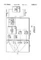
- FIG. 3illustrates a full duplex system in accordance with the present invention.
- FIG. 4illustrates a detailed block diagram of the echo time determiner in accordance with the present invention.
- FIG. 5illustrates a logic diagram that may be used to implement the present invention.
- the present inventionprovides a method and apparatus for determining echo cancellation time. This may be accomplished by providing an echo time determiner that samples signals on either the transmit path or the receive path. Once sampled, the signal samples are filtered via smoothing filter using a first smoothing parameter. Each filtered signal sample is then sequentially compared with a first predetermined threshold until one of the filtered signal samples is favorable with the first predetermined threshold. When this occurs, the beginning echo time is determined, the smoothing parameter is adjusted to a second smoothing parameter, and the threshold is adjusted to a second predetermined threshold. Upon making these adjustments, the remaining signal samples are filtered via the smoothing filter using the second smoothing parameter.
- filtered signalsare then sequentially compared to the second threshold until one of the second filtered signals is favorable with the second predetermined threshold. When this occurs, the trailing edge of the echo is determined. Having determined the beginning and the end of the echo, the duration of the echo can be utilized by the echo cancellation circuit 301 to provide an accurate duration for echo cancellation. By accurately determining the echo time, unnecessary mathematical computations may be avoided thus reducing total noise of the overall system.
- FIG. 3illustrates a full duplex system 300 which includes a plurality of microphones 101-1 to 101 -N and a plurality of speakers 102-1 to 101-N positioned throughout an acoustic room 103.
- the number of speakers 102 and microphones 101 and their positioningwill be dependent upon the size of the room 103. For example, if the room is relatively small, say 3 meters by 3 meters, only one microphone and one speaker may be used. If, however, the room 103 is a large conference room, such as a teleconferencing room that includes audio and/or visual communication equipment, multiple microphones and speakers are needed to provide adequate audio reception and detection.
- a telephone 104which includes a plurality of analog-to-digital converters 303-1 to 303-N, a plurality of digital-to-analog converts 304-1 to 304-N, an echo cancellation circuit 301 and an echo timed determiner 302.
- Each of the analog-to-digital converters 303are connected to a respective microphone 101, while each of the digital-to-analog converts 304 are connected to a respective speaker 102.
- the echo cancellation circuit 301which may be an echo cancellation circuit as described in the above mentioned U.S. Pat. No. 5,410,595, receives electrical echoes and acoustic echoes via the receive path 106 and the transmit path 105, respectively.
- the echo cancellation circuit 301also receives input from the echo time determiner 302, which is coupled to the receive path 106 and the transmit path 107.
- the echo time determiner 302samples the transmit path 105 for acoustic echoes and/or the receiving path 106 for electrical echoes.
- acoustic echoesare produced by audio signals, which were rendered audible by the speakers, bouncing or reflecting off the walls, ceiling, and floor of the acoustic room 103 and being received by microphones 101.
- Electrical echoesare generated as a result of the transmit path, the phone line interface 109 and the receive path transfer function. Based on the transfer function, signals present on the transmit path 105 are leaked via the phone line interface 109 on the receive path 106.
- the echo time determiner 302Based on which type echo is being sensed, the echo time determiner 302 provides an exact echo duration to the echo cancellation circuit 301 such that the echo cancellation circuit 301 may effectively cancel the echo. By having an exact echo duration, unnecessary processing steps and calculations are avoided. Thus, processing time and energy are saved as well as reducing overall noise.
- FIG. 4illustrates a detailed schematic block diagram of the echo time determiner 302.
- a sampler 400receives signals via the transmit path 105 and/or the receive path 106. While the echo time determined 302 is shown having both the transmit path and receive path 106 providing inputs, the determiner 302 may only receive one of the signals. For example, the determiner 302 may be used for electrical cancellations, thus it would only be coupled to the receive path 106. Conversely, if the determiner 302 is used for acoustic echoes only, the sampler 400 would receive inputs from the transmit path 105.
- the sampler 400produces a series of signal samples 401 by sampling signals on the respective path 105-106.
- the series of signal samples 401are provided to a smoothing filter 402 which produces a series of filtered signal samples 403.
- the series of filtered samples 403are then sequentially compared, via a comparator 404, with a predetermined threshold 405, wherein, the predetermined threshold is initially set at a first level 405.
- the sequential comparison of the filtered samples 403 to the first predetermined thresholdis as the term implies.
- Each time consecutive filtered sampleis compared with the first threshold 405, if this comparison is not favorable, the next time sequenced filtered sample is compared. This single sample comparison continues until one of the filtered samples is favorable to the first threshold.
- when one of the filtered samples is favorable to the first predetermined thresholdrefers to the condition when the filter sample is greater than the predetermined threshold.
- a favorable relationshipmay be obtained in a variety of ways. For example, the polarity of the comparator could be switched, the signals could be inverted, scaled, etc.
- an echo time estimator 406When a filtered signal sample exceed the first predetermined threshold, an echo time estimator 406 generates a first arrival time of an echo 407. In other words, the echo time estimator 406 time stamps the first detection of the echo. Upon time stamping the echo, the echo time estimator 406 generates a smoothing parameter adjustment signal and a predetermined threshold adjustment signal.
- the smoothing parameter adjustment signalcauses the smoothing filter 402 to adjust its smoothing parameter to a second smoothing parameter.
- the threshold adjustment signalcauses the threshold 405 to be switched to a second predetermined threshold.
- the echo time determiner 302continues to sample the echo, filter the samples, and compare the remaining filter samples using the second smoothing parameter and the second predetermined threshold 405.
- the echo time estimator 406indicates end time of echo 407.
- the echo time estimator 406indicates the end of echo by time stamping when the second filtered sample is favorable to the second predetermined threshold.
- the durationis readily calculable and provided to the echo cancellation circuit 301.
- when the second filtered sample is favorable to the second predetermined thresholdrefers to the condition when the second filtered signal sample is less than the second predetermined threshold.
- a favorable conditionmay be arrived at in a variety of ways, which have been mentioned above.
- the smoothing filter 402filters the signal samples using either the first smoothing parameter or the second smoothing parameter.
- the smoothing filterincludes an absolute value determiner 408, a first multiplier 409, a summer 410, a time delay 412, and a second multiplier 411.
- the first multiplier 409is shown to have a multiplication factor, of 1- ⁇ while the second multiplier 411 is shown to have a multiplication factor of ⁇ .
- the first smoothing parameteris approximately B equal to 0.9
- the second smoothing parameteris approximately B equal to 0.99. Utilizing these smoothing parameters, the invention accurately determines the duration of the echo.
- the echo time determiner 302comprises a plurality of discrete elements. While the echo time determiner 302 may be implemented using discrete hardware components, it may also be implemented in a digital signal processor (DSP), Due to the essentially mathematical operation of the echo time determiner 302, the preferred embodiment is to implement the echo time determiner 302 and the echo cancellation circuit 301 in a DSP.
- DSPdigital signal processor
- the discussionhas primarily focused on determining an echo duration for a single microphone.
- the system 300is shown having a plurality of microphones 101 and a plurality of speakers 102.
- an echo durationmust be calculated.
- one of the microphones and all of the speakersare enabled while the remaining microphones are disabled.
- an audible test impulse, or other audible signalis supplied to the plurality of speakers which render the signal audible.
- the one enabled microphonereceives the audible signal and the above described echo duration process is evoked. Having performed this for one microphone, this microphone is disabled and another is enabled until each microphone has been tested.
- FIG. 5illustrates a logic diagram that may be used to implement the present invention.
- an audible test signalis provided on one of the transmit or receive paths.
- This audible test signalmay be digitally generated to be a short duration tone such that echo durations can be determined.
- the audible test signalmay be voice patterns stored within the telephone, or voice patterns that are active during a full duplex, or teleconferencing, phone call.
- the signal's echois sampled to produce a series of signal samples 501.
- the series of signal samplesare sequentially filtered using a first smoothing parameter to produce filtered signal samples 502.
- the filtered signal samplesare then compared to a first predetermined threshold in a sequential order 503. If the comparison is unfavorable 504, the process continues at 502.
- the filtered signal samplesare sequentially compared to the first predetermined threshold until one of the filtered signal samples is favorable to the first predetermined threshold 504.
- an indication of first arrival time of an echois set 505.
- the smoothing parameteris adjusted to a second smoothing parameter 506 and the predetermined threshold is adjusted to a second predetermined threshold. Having made these adjustments, the remaining signal samples of the echo are filtered utilizing the second smoothing parameter 505.
- Each of the second filtered signal samplesare then compared with the second predetermined threshold 508, until a favorable indication is received 509. If a favorable indication is not received, the process repeats at 507. Once a favorable comparison is made 509, an end time of echo is indicated 510.
- the duration of the echocan be accurately determined. Note that, in practice, the first arrival time of an echo will be t 1 and the end time of an echo will be t 2 as shown in FIG. 2. Having determined the echo duration, the process repeats at step 500 for the next calculation.
- the present inventionprovides a method and apparatus for determining echo time duration.
- an echo cancellation circuitmay be adjusted to perform the mathematical operations to cancel the exact echo.
- unnecessary mathematical and processing stepsare eliminated thus saving processing power and reducing the total noise which results from performing unnecessary mathematical operations.
- variable echo time cancellationlarge echoes may be completely canceled whereas in prior art systems of fixed echo durations this was not the case.
Landscapes
- Engineering & Computer Science (AREA)
- Signal Processing (AREA)
- Telephone Function (AREA)
- Cable Transmission Systems, Equalization Of Radio And Reduction Of Echo (AREA)
Abstract
Description
Claims (13)
Priority Applications (2)
| Application Number | Priority Date | Filing Date | Title |
|---|---|---|---|
| US08/283,322US5502717A (en) | 1994-08-01 | 1994-08-01 | Method and apparatus for estimating echo cancellation time |
| EP95112022AEP0696126A1 (en) | 1994-08-01 | 1995-07-31 | Method and apparatus for estimating echo cancellation time |
Applications Claiming Priority (1)
| Application Number | Priority Date | Filing Date | Title |
|---|---|---|---|
| US08/283,322US5502717A (en) | 1994-08-01 | 1994-08-01 | Method and apparatus for estimating echo cancellation time |
Publications (1)
| Publication Number | Publication Date |
|---|---|
| US5502717Atrue US5502717A (en) | 1996-03-26 |
Family
ID=23085472
Family Applications (1)
| Application Number | Title | Priority Date | Filing Date |
|---|---|---|---|
| US08/283,322Expired - LifetimeUS5502717A (en) | 1994-08-01 | 1994-08-01 | Method and apparatus for estimating echo cancellation time |
Country Status (2)
| Country | Link |
|---|---|
| US (1) | US5502717A (en) |
| EP (1) | EP0696126A1 (en) |
Cited By (9)
| Publication number | Priority date | Publication date | Assignee | Title |
|---|---|---|---|---|
| US5887059A (en)* | 1996-01-30 | 1999-03-23 | Advanced Micro Devices, Inc. | System and method for performing echo cancellation in a communications network employing a mixed mode LMS adaptive balance filter |
| US6266408B1 (en)* | 1996-10-28 | 2001-07-24 | Samsung Electronics Co., Ltd. | Echo controlling apparatus of video conferencing system and control method using the same |
| US20010016783A1 (en)* | 1997-06-25 | 2001-08-23 | Graumann David L. | Method and apparatus for active latency characterization |
| US6381224B1 (en) | 1999-03-31 | 2002-04-30 | Motorola, Inc. | Method and apparatus for controlling a full-duplex communication system |
| US6580795B1 (en) | 1999-10-14 | 2003-06-17 | Motorola, Inc. | Echo canceller for a full-duplex communication system and method therefor |
| US7035396B1 (en)* | 1999-01-22 | 2006-04-25 | Agere Systems Inc. | Configurable echo canceller |
| US20130230152A1 (en)* | 2008-12-02 | 2013-09-05 | Cisco Technology, Inc. | Echo mitigation in a conference call |
| US8880058B2 (en)* | 2012-09-14 | 2014-11-04 | Toyota Motor Engineering & Manufacturing North America, Inc. | Automatic tuning system |
| CN113499538A (en)* | 2016-08-01 | 2021-10-15 | 心脏器械股份有限公司 | Heart rate determination based on VAD current waveform |
Families Citing this family (1)
| Publication number | Priority date | Publication date | Assignee | Title |
|---|---|---|---|---|
| FR2995122B1 (en) | 2012-09-06 | 2015-09-04 | Sagemcom Broadband Sas | DEVICE AND METHOD FOR PROVIDING A REFERENCE AUDIO SIGNAL TO AN ACOUSTIC PROCESSING UNIT |
Citations (8)
| Publication number | Priority date | Publication date | Assignee | Title |
|---|---|---|---|---|
| US4628529A (en)* | 1985-07-01 | 1986-12-09 | Motorola, Inc. | Noise suppression system |
| US4630305A (en)* | 1985-07-01 | 1986-12-16 | Motorola, Inc. | Automatic gain selector for a noise suppression system |
| US4805215A (en)* | 1986-10-01 | 1989-02-14 | Racal Data Communications Inc. | Adaptive echo canceller with sparse dynamically positioned taps |
| US4823382A (en)* | 1986-10-01 | 1989-04-18 | Racal Data Communications Inc. | Echo canceller with dynamically positioned adaptive filter taps |
| US4956838A (en)* | 1988-03-15 | 1990-09-11 | Etat Francais Represente Par Le Ministre Des Postes, Telecommunications Et De L'espace (Centre National D'etudes Des Telecommunications) | Echo cancelling device with frequency sub-band filtering |
| US5050160A (en)* | 1989-06-13 | 1991-09-17 | Nec Corporation | Training method for an echo canceller for use in a voice conference system |
| US5062102A (en)* | 1988-12-01 | 1991-10-29 | Nec Corporation | Echo canceller with means for determining filter coefficients from autocorrelation and cross-correlation coefficients |
| US5195138A (en)* | 1990-01-18 | 1993-03-16 | Matsushita Electric Industrial Co., Ltd. | Voice signal processing device |
Family Cites Families (3)
| Publication number | Priority date | Publication date | Assignee | Title |
|---|---|---|---|---|
| US4959857A (en)* | 1988-12-28 | 1990-09-25 | At&T Bell Laboratories | Acoustic calibration arrangement for a voice switched speakerphone |
| JP2503747B2 (en)* | 1990-09-12 | 1996-06-05 | 日本電気株式会社 | FIR type eco-canceller |
| CA2086522C (en)* | 1991-04-30 | 1996-12-24 | Yuji Umemoto | Speech communication apparatus equipped with echo canceller |
- 1994
- 1994-08-01USUS08/283,322patent/US5502717A/ennot_activeExpired - Lifetime
- 1995
- 1995-07-31EPEP95112022Apatent/EP0696126A1/ennot_activeCeased
Patent Citations (8)
| Publication number | Priority date | Publication date | Assignee | Title |
|---|---|---|---|---|
| US4628529A (en)* | 1985-07-01 | 1986-12-09 | Motorola, Inc. | Noise suppression system |
| US4630305A (en)* | 1985-07-01 | 1986-12-16 | Motorola, Inc. | Automatic gain selector for a noise suppression system |
| US4805215A (en)* | 1986-10-01 | 1989-02-14 | Racal Data Communications Inc. | Adaptive echo canceller with sparse dynamically positioned taps |
| US4823382A (en)* | 1986-10-01 | 1989-04-18 | Racal Data Communications Inc. | Echo canceller with dynamically positioned adaptive filter taps |
| US4956838A (en)* | 1988-03-15 | 1990-09-11 | Etat Francais Represente Par Le Ministre Des Postes, Telecommunications Et De L'espace (Centre National D'etudes Des Telecommunications) | Echo cancelling device with frequency sub-band filtering |
| US5062102A (en)* | 1988-12-01 | 1991-10-29 | Nec Corporation | Echo canceller with means for determining filter coefficients from autocorrelation and cross-correlation coefficients |
| US5050160A (en)* | 1989-06-13 | 1991-09-17 | Nec Corporation | Training method for an echo canceller for use in a voice conference system |
| US5195138A (en)* | 1990-01-18 | 1993-03-16 | Matsushita Electric Industrial Co., Ltd. | Voice signal processing device |
Non-Patent Citations (4)
| Title |
|---|
| Sangil Park, "Full Duplex Speakerphone with Acoustic and Electric Echo-Canceller utilizing the DSP56200 Cascadable Adaptive Fir Filter Chip", Proc. of Midcon/90 Technical Conference on Electronic and Electrical Technology, Dallas, TX, Sep. 11-13, 1990. |
| Sangil Park, Full Duplex Speakerphone with Acoustic and Electric Echo Canceller utilizing the DSP56200 Cascadable Adaptive Fir Filter Chip , Proc. of Midcon/90 Technical Conference on Electronic and Electrical Technology, Dallas, TX, Sep. 11 13, 1990.* |
| Widrow et al. `Adaptive Noise Cancelling: Principles and Applications' Proceedings of the IEEE 63, No. 12 Dec 1975 (1692-1716). |
| Widrow et al. Adaptive Noise Cancelling: Principles and Applications Proceedings of the IEEE 63, No. 12 Dec 1975 (1692 1716).* |
Cited By (11)
| Publication number | Priority date | Publication date | Assignee | Title |
|---|---|---|---|---|
| US5887059A (en)* | 1996-01-30 | 1999-03-23 | Advanced Micro Devices, Inc. | System and method for performing echo cancellation in a communications network employing a mixed mode LMS adaptive balance filter |
| US6266408B1 (en)* | 1996-10-28 | 2001-07-24 | Samsung Electronics Co., Ltd. | Echo controlling apparatus of video conferencing system and control method using the same |
| US20010016783A1 (en)* | 1997-06-25 | 2001-08-23 | Graumann David L. | Method and apparatus for active latency characterization |
| US7046795B2 (en)* | 1997-06-25 | 2006-05-16 | Intel Corporation | Method and apparatus for active latency characterization |
| US7035396B1 (en)* | 1999-01-22 | 2006-04-25 | Agere Systems Inc. | Configurable echo canceller |
| US6381224B1 (en) | 1999-03-31 | 2002-04-30 | Motorola, Inc. | Method and apparatus for controlling a full-duplex communication system |
| US6580795B1 (en) | 1999-10-14 | 2003-06-17 | Motorola, Inc. | Echo canceller for a full-duplex communication system and method therefor |
| US20130230152A1 (en)* | 2008-12-02 | 2013-09-05 | Cisco Technology, Inc. | Echo mitigation in a conference call |
| US9083776B2 (en)* | 2008-12-02 | 2015-07-14 | Cisco Technology, Inc. | Echo mitigation in a conference call |
| US8880058B2 (en)* | 2012-09-14 | 2014-11-04 | Toyota Motor Engineering & Manufacturing North America, Inc. | Automatic tuning system |
| CN113499538A (en)* | 2016-08-01 | 2021-10-15 | 心脏器械股份有限公司 | Heart rate determination based on VAD current waveform |
Also Published As
| Publication number | Publication date |
|---|---|
| EP0696126A1 (en) | 1996-02-07 |
Similar Documents
| Publication | Publication Date | Title |
|---|---|---|
| US5646990A (en) | Efficient speakerphone anti-howling system | |
| US6792107B2 (en) | Double-talk detector suitable for a telephone-enabled PC | |
| US6904146B2 (en) | Full duplex echo cancelling circuit | |
| EP1324583B1 (en) | Gain control method for acoustic echo cancellation | |
| EP0376582B1 (en) | Computer controlled adaptive speakerphone | |
| US6928160B2 (en) | Estimating bulk delay in a telephone system | |
| US6574336B1 (en) | Echo suppressor and non-linear processor of echo canceller | |
| US5390244A (en) | Method and apparatus for periodic signal detection | |
| US8391472B2 (en) | Acoustic echo cancellation solution for video conferencing | |
| EP0597201A1 (en) | Apparatus and method for noise reduction for a full-duplex speakerphone or the like | |
| US6611601B2 (en) | Echo sound signal suppressing apparatus | |
| EP0221221A1 (en) | A process for determining an echo path flat delay and echo canceler using said process | |
| US4571461A (en) | Conference telephone apparatus | |
| WO1993005597A1 (en) | Adaptive echo canceller for voice messaging system | |
| US6381224B1 (en) | Method and apparatus for controlling a full-duplex communication system | |
| US6385176B1 (en) | Communication system based on echo canceler tap profile | |
| US5502717A (en) | Method and apparatus for estimating echo cancellation time | |
| CN110995951A (en) | Echo cancellation method, device and system based on double-end sounding detection | |
| EP0778714A2 (en) | Software-based bridging system for full duplex audio telephone conferencing | |
| JPS634985B2 (en) | ||
| US20030235293A1 (en) | Adaptive system control | |
| JPS62116025A (en) | Echo canceler | |
| WO1997007624A1 (en) | Echo cancelling using signal preprocessing in an acoustic environment | |
| Yasukawa et al. | Echo return loss required for acoustic echo canceller based on subjective assessment | |
| US7450528B1 (en) | Method and apparatus for performing echo suppression |
Legal Events
| Date | Code | Title | Description |
|---|---|---|---|
| AS | Assignment | Owner name:MOTOROLA, INC., ILLINOIS Free format text:ASSIGNMENT OF ASSIGNORS INTEREST;ASSIGNOR:PARK, SANGIL;REEL/FRAME:007116/0398 Effective date:19940729 | |
| STCF | Information on status: patent grant | Free format text:PATENTED CASE | |
| FPAY | Fee payment | Year of fee payment:4 | |
| FPAY | Fee payment | Year of fee payment:8 | |
| AS | Assignment | Owner name:FREESCALE SEMICONDUCTOR, INC., TEXAS Free format text:ASSIGNMENT OF ASSIGNORS INTEREST;ASSIGNOR:MOTOROLA, INC.;REEL/FRAME:015698/0657 Effective date:20040404 Owner name:FREESCALE SEMICONDUCTOR, INC.,TEXAS Free format text:ASSIGNMENT OF ASSIGNORS INTEREST;ASSIGNOR:MOTOROLA, INC.;REEL/FRAME:015698/0657 Effective date:20040404 | |
| AS | Assignment | Owner name:CITIBANK, N.A. AS COLLATERAL AGENT, NEW YORK Free format text:SECURITY AGREEMENT;ASSIGNORS:FREESCALE SEMICONDUCTOR, INC.;FREESCALE ACQUISITION CORPORATION;FREESCALE ACQUISITION HOLDINGS CORP.;AND OTHERS;REEL/FRAME:018855/0129 Effective date:20061201 Owner name:CITIBANK, N.A. AS COLLATERAL AGENT,NEW YORK Free format text:SECURITY AGREEMENT;ASSIGNORS:FREESCALE SEMICONDUCTOR, INC.;FREESCALE ACQUISITION CORPORATION;FREESCALE ACQUISITION HOLDINGS CORP.;AND OTHERS;REEL/FRAME:018855/0129 Effective date:20061201 | |
| FPAY | Fee payment | Year of fee payment:12 | |
| AS | Assignment | Owner name:CITIBANK, N.A., AS COLLATERAL AGENT,NEW YORK Free format text:SECURITY AGREEMENT;ASSIGNOR:FREESCALE SEMICONDUCTOR, INC.;REEL/FRAME:024397/0001 Effective date:20100413 Owner name:CITIBANK, N.A., AS COLLATERAL AGENT, NEW YORK Free format text:SECURITY AGREEMENT;ASSIGNOR:FREESCALE SEMICONDUCTOR, INC.;REEL/FRAME:024397/0001 Effective date:20100413 | |
| AS | Assignment | Owner name:CITIBANK, N.A., AS NOTES COLLATERAL AGENT, NEW YORK Free format text:SECURITY AGREEMENT;ASSIGNOR:FREESCALE SEMICONDUCTOR, INC.;REEL/FRAME:030633/0424 Effective date:20130521 Owner name:CITIBANK, N.A., AS NOTES COLLATERAL AGENT, NEW YOR Free format text:SECURITY AGREEMENT;ASSIGNOR:FREESCALE SEMICONDUCTOR, INC.;REEL/FRAME:030633/0424 Effective date:20130521 | |
| AS | Assignment | Owner name:ZENITH INVESTMENTS, LLC, DELAWARE Free format text:ASSIGNMENT OF ASSIGNORS INTEREST;ASSIGNOR:FREESCALE SEMICONDUCTOR, INC.;REEL/FRAME:033677/0942 Effective date:20130610 | |
| AS | Assignment | Owner name:APPLE INC., CALIFORNIA Free format text:ASSIGNMENT OF ASSIGNORS INTEREST;ASSIGNOR:ZENITH INVESTMENTS, LLC;REEL/FRAME:034749/0791 Effective date:20141219 | |
| AS | Assignment | Owner name:FREESCALE SEMICONDUCTOR, INC., TEXAS Free format text:PATENT RELEASE;ASSIGNOR:CITIBANK, N.A., AS COLLATERAL AGENT;REEL/FRAME:037354/0225 Effective date:20151207 Owner name:FREESCALE SEMICONDUCTOR, INC., TEXAS Free format text:PATENT RELEASE;ASSIGNOR:CITIBANK, N.A., AS COLLATERAL AGENT;REEL/FRAME:037356/0553 Effective date:20151207 Owner name:FREESCALE SEMICONDUCTOR, INC., TEXAS Free format text:PATENT RELEASE;ASSIGNOR:CITIBANK, N.A., AS COLLATERAL AGENT;REEL/FRAME:037356/0143 Effective date:20151207 | |
| AS | Assignment | Owner name:MORGAN STANLEY SENIOR FUNDING, INC., MARYLAND Free format text:ASSIGNMENT AND ASSUMPTION OF SECURITY INTEREST IN PATENTS;ASSIGNOR:CITIBANK, N.A.;REEL/FRAME:037486/0517 Effective date:20151207 | |
| AS | Assignment | Owner name:NXP, B.V., F/K/A FREESCALE SEMICONDUCTOR, INC., NETHERLANDS Free format text:RELEASE BY SECURED PARTY;ASSIGNOR:MORGAN STANLEY SENIOR FUNDING, INC.;REEL/FRAME:040925/0001 Effective date:20160912 Owner name:NXP, B.V., F/K/A FREESCALE SEMICONDUCTOR, INC., NE Free format text:RELEASE BY SECURED PARTY;ASSIGNOR:MORGAN STANLEY SENIOR FUNDING, INC.;REEL/FRAME:040925/0001 Effective date:20160912 | |
| AS | Assignment | Owner name:NXP B.V., NETHERLANDS Free format text:RELEASE BY SECURED PARTY;ASSIGNOR:MORGAN STANLEY SENIOR FUNDING, INC.;REEL/FRAME:040928/0001 Effective date:20160622 | |
| AS | Assignment | Owner name:MORGAN STANLEY SENIOR FUNDING, INC., MARYLAND Free format text:CORRECTIVE ASSIGNMENT TO CORRECT THE REMOVE APPLICATION11759915 AND REPLACE IT WITH APPLICATION 11759935 PREVIOUSLY RECORDED ON REEL 037486 FRAME 0517. ASSIGNOR(S) HEREBY CONFIRMS THE ASSIGNMENT AND ASSUMPTION OF SECURITYINTEREST IN PATENTS;ASSIGNOR:CITIBANK, N.A.;REEL/FRAME:053547/0421 Effective date:20151207 | |
| AS | Assignment | Owner name:NXP B.V., NETHERLANDS Free format text:CORRECTIVE ASSIGNMENT TO CORRECT THE REMOVEAPPLICATION 11759915 AND REPLACE IT WITH APPLICATION11759935 PREVIOUSLY RECORDED ON REEL 040928 FRAME 0001. ASSIGNOR(S) HEREBY CONFIRMS THE RELEASE OF SECURITYINTEREST;ASSIGNOR:MORGAN STANLEY SENIOR FUNDING, INC.;REEL/FRAME:052915/0001 Effective date:20160622 | |
| AS | Assignment | Owner name:NXP, B.V. F/K/A FREESCALE SEMICONDUCTOR, INC., NETHERLANDS Free format text:CORRECTIVE ASSIGNMENT TO CORRECT THE REMOVEAPPLICATION 11759915 AND REPLACE IT WITH APPLICATION11759935 PREVIOUSLY RECORDED ON REEL 040925 FRAME 0001. ASSIGNOR(S) HEREBY CONFIRMS THE RELEASE OF SECURITYINTEREST;ASSIGNOR:MORGAN STANLEY SENIOR FUNDING, INC.;REEL/FRAME:052917/0001 Effective date:20160912 |