US5501872A - Method and apparatus for coating a six-sided fibrous batting - Google Patents
Method and apparatus for coating a six-sided fibrous battingDownload PDFInfo
- Publication number
- US5501872A US5501872AUS08/425,973US42597395AUS5501872AUS 5501872 AUS5501872 AUS 5501872AUS 42597395 AUS42597395 AUS 42597395AUS 5501872 AUS5501872 AUS 5501872A
- Authority
- US
- United States
- Prior art keywords
- batt
- coating
- dies
- meltblowing
- station
- Prior art date
- Legal status (The legal status is an assumption and is not a legal conclusion. Google has not performed a legal analysis and makes no representation as to the accuracy of the status listed.)
- Expired - Fee Related
Links
- 238000000576coating methodMethods0.000titleclaimsabstractdescription86
- 239000011248coating agentSubstances0.000titleclaimsabstractdescription70
- 238000000034methodMethods0.000titleclaimsdescription27
- 239000000463materialSubstances0.000claimsabstractdescription11
- 229920000642polymerPolymers0.000claimsdescription35
- 239000000835fiberSubstances0.000claimsdescription32
- 230000033001locomotionEffects0.000claimsdescription16
- 229920001169thermoplasticPolymers0.000claimsdescription15
- 239000004416thermosoftening plasticSubstances0.000claimsdescription15
- -1polypropylenePolymers0.000claimsdescription9
- 239000004743PolypropyleneSubstances0.000claimsdescription5
- 229920001155polypropylenePolymers0.000claimsdescription5
- VGGSQFUCUMXWEO-UHFFFAOYSA-NEtheneChemical compoundC=CVGGSQFUCUMXWEO-UHFFFAOYSA-N0.000claimsdescription3
- 239000005977EthyleneSubstances0.000claimsdescription3
- 230000003213activating effectEffects0.000claimsdescription2
- 229920001577copolymerPolymers0.000claimsdescription2
- 229920000098polyolefinPolymers0.000claimsdescription2
- QQONPFPTGQHPMA-UHFFFAOYSA-NpropyleneNatural productsCC=CQQONPFPTGQHPMA-UHFFFAOYSA-N0.000claimsdescription2
- 125000004805propylene groupChemical group[H]C([H])([H])C([H])([*:1])C([H])([H])[*:2]0.000claimsdescription2
- 238000010276constructionMethods0.000description7
- 230000008569processEffects0.000description6
- 238000009413insulationMethods0.000description5
- 239000002657fibrous materialSubstances0.000description4
- 238000004140cleaningMethods0.000description3
- 238000005538encapsulationMethods0.000description3
- 229920005989resinPolymers0.000description3
- 239000011347resinSubstances0.000description3
- 239000002893slagSubstances0.000description3
- 239000007921spraySubstances0.000description3
- 210000002268woolAnatomy0.000description3
- 230000009471actionEffects0.000description2
- 239000000853adhesiveSubstances0.000description2
- 230000001070adhesive effectEffects0.000description2
- 238000007599dischargingMethods0.000description2
- 239000003365glass fiberSubstances0.000description2
- 239000012212insulatorSubstances0.000description2
- 239000000155meltSubstances0.000description2
- 239000011435rockSubstances0.000description2
- 238000007789sealingMethods0.000description2
- 239000012815thermoplastic materialSubstances0.000description2
- 239000004677NylonSubstances0.000description1
- 239000004952PolyamideSubstances0.000description1
- 239000004793PolystyreneSubstances0.000description1
- UCKMPCXJQFINFW-UHFFFAOYSA-NSulphideChemical compound[S-2]UCKMPCXJQFINFW-UHFFFAOYSA-N0.000description1
- 239000002250absorbentSubstances0.000description1
- 230000002745absorbentEffects0.000description1
- 229920006243acrylic copolymerPolymers0.000description1
- 230000008901benefitEffects0.000description1
- 230000005540biological transmissionEffects0.000description1
- 229920001971elastomerPolymers0.000description1
- 229920006225ethylene-methyl acrylatePolymers0.000description1
- 239000012467final productSubstances0.000description1
- 239000012530fluidSubstances0.000description1
- 229920001519homopolymerPolymers0.000description1
- 230000000977initiatory effectEffects0.000description1
- 229910052500inorganic mineralInorganic materials0.000description1
- 238000009434installationMethods0.000description1
- 239000011810insulating materialSubstances0.000description1
- 239000011707mineralSubstances0.000description1
- 239000002557mineral fiberSubstances0.000description1
- 239000000203mixtureSubstances0.000description1
- 239000004745nonwoven fabricSubstances0.000description1
- 229920001778nylonPolymers0.000description1
- 230000003287optical effectEffects0.000description1
- 230000035699permeabilityEffects0.000description1
- 229920003229poly(methyl methacrylate)Polymers0.000description1
- 229920002647polyamidePolymers0.000description1
- 229920000728polyesterPolymers0.000description1
- 239000005020polyethylene terephthalateSubstances0.000description1
- 229920000139polyethylene terephthalatePolymers0.000description1
- 229920002959polymer blendPolymers0.000description1
- 229920005594polymer fiberPolymers0.000description1
- 239000004926polymethyl methacrylateSubstances0.000description1
- 229920001296polysiloxanePolymers0.000description1
- 229920002223polystyrenePolymers0.000description1
- 238000005507sprayingMethods0.000description1
- 229920005992thermoplastic resinPolymers0.000description1
- 230000032258transportEffects0.000description1
Images


Classifications
- E—FIXED CONSTRUCTIONS
- E04—BUILDING
- E04B—GENERAL BUILDING CONSTRUCTIONS; WALLS, e.g. PARTITIONS; ROOFS; FLOORS; CEILINGS; INSULATION OR OTHER PROTECTION OF BUILDINGS
- E04B1/00—Constructions in general; Structures which are not restricted either to walls, e.g. partitions, or floors or ceilings or roofs
- E04B1/62—Insulation or other protection; Elements or use of specified material therefor
- E04B1/74—Heat, sound or noise insulation, absorption, or reflection; Other building methods affording favourable thermal or acoustical conditions, e.g. accumulating of heat within walls
- E04B1/76—Heat, sound or noise insulation, absorption, or reflection; Other building methods affording favourable thermal or acoustical conditions, e.g. accumulating of heat within walls specifically with respect to heat only
- E04B1/7654—Heat, sound or noise insulation, absorption, or reflection; Other building methods affording favourable thermal or acoustical conditions, e.g. accumulating of heat within walls specifically with respect to heat only comprising an insulating layer, disposed between two longitudinal supporting elements, e.g. to insulate ceilings
- E04B1/7658—Heat, sound or noise insulation, absorption, or reflection; Other building methods affording favourable thermal or acoustical conditions, e.g. accumulating of heat within walls specifically with respect to heat only comprising an insulating layer, disposed between two longitudinal supporting elements, e.g. to insulate ceilings comprising fiber insulation, e.g. as panels or loose filled fibres
- E04B1/7662—Heat, sound or noise insulation, absorption, or reflection; Other building methods affording favourable thermal or acoustical conditions, e.g. accumulating of heat within walls specifically with respect to heat only comprising an insulating layer, disposed between two longitudinal supporting elements, e.g. to insulate ceilings comprising fiber insulation, e.g. as panels or loose filled fibres comprising fiber blankets or batts
- D—TEXTILES; PAPER
- D04—BRAIDING; LACE-MAKING; KNITTING; TRIMMINGS; NON-WOVEN FABRICS
- D04H—MAKING TEXTILE FABRICS, e.g. FROM FIBRES OR FILAMENTARY MATERIAL; FABRICS MADE BY SUCH PROCESSES OR APPARATUS, e.g. FELTS, NON-WOVEN FABRICS; COTTON-WOOL; WADDING ; NON-WOVEN FABRICS FROM STAPLE FIBRES, FILAMENTS OR YARNS, BONDED WITH AT LEAST ONE WEB-LIKE MATERIAL DURING THEIR CONSOLIDATION
- D04H1/00—Non-woven fabrics formed wholly or mainly of staple fibres or like relatively short fibres
- D04H1/40—Non-woven fabrics formed wholly or mainly of staple fibres or like relatively short fibres from fleeces or layers composed of fibres without existing or potential cohesive properties
- D04H1/54—Non-woven fabrics formed wholly or mainly of staple fibres or like relatively short fibres from fleeces or layers composed of fibres without existing or potential cohesive properties by welding together the fibres, e.g. by partially melting or dissolving
- D04H1/56—Non-woven fabrics formed wholly or mainly of staple fibres or like relatively short fibres from fleeces or layers composed of fibres without existing or potential cohesive properties by welding together the fibres, e.g. by partially melting or dissolving in association with fibre formation, e.g. immediately following extrusion of staple fibres
- E—FIXED CONSTRUCTIONS
- E04—BUILDING
- E04B—GENERAL BUILDING CONSTRUCTIONS; WALLS, e.g. PARTITIONS; ROOFS; FLOORS; CEILINGS; INSULATION OR OTHER PROTECTION OF BUILDINGS
- E04B1/00—Constructions in general; Structures which are not restricted either to walls, e.g. partitions, or floors or ceilings or roofs
- E04B1/62—Insulation or other protection; Elements or use of specified material therefor
- E04B1/74—Heat, sound or noise insulation, absorption, or reflection; Other building methods affording favourable thermal or acoustical conditions, e.g. accumulating of heat within walls
- E04B1/76—Heat, sound or noise insulation, absorption, or reflection; Other building methods affording favourable thermal or acoustical conditions, e.g. accumulating of heat within walls specifically with respect to heat only
- E04B1/78—Heat insulating elements
Definitions
- the present inventionrelates to a method and apparatus for coating and/or encapsulating a six-sided fibrous object or batting with thermoplastic material.
- Insulating materialsare frequently manufactured in the form of six-sided objects, referred to herein as batting, from fibrous materials such as rock fibers, glass fibers, slag fibers, wool fibers, and the like. These materials are used as thermal and acoustic insulators in a variety of applications.
- fibrous materialssuch as rock fibers, glass fibers, slag fibers, wool fibers, and the like. These materials are used as thermal and acoustic insulators in a variety of applications.
- One problem associated with the fibrous battingis that its fibrous nature causes surface fibers to break away from the batting, particularly on handling. This not only can reduce the effectiveness of the insulator, but can also contaminate the atmosphere with fibers. In order to prevent this, it has been a common practice to coat the batting with a thermoplastic material. Preformed nonwoven web material composed of polymer fibers has been adhered to the surface of fibrous batting.
- PCT Application No. PCT/DK93/00064discloses a method of applying a polymer coating onto a batting surface.
- the apparatus disclosed in the PCT applicationincludes (a) a meltblowing die wherein micro-sized thermoplastic fibers are applied to a fibrous surface by the meltblowing process, and (b) melt spray nozzles wherein a gas/polymer mixture is applied to the fibrous surface.
- a number of nozzles arranged in a line across the surface to be coateddischarge the gas/polymer stream onto the batting surface.
- a number of such nozzles, or pressure guns,can also be positioned circumferentially around the batting to coat four sides of the batting.
- the PCT applicationdiscloses coating four sides using the melt spray apparatus, it discloses only the coating of the upper and lower sides using the meltblowing apparatus.
- a suction device in accordance with the teachings of the PCT applicationis required to be positioned on the opposite side of the surface being coated. Because the batting generally is much wider than thick, the suction device could not be used in coating the sides of a thick batting.
- Meltblowingoffers the advantage over melt-spraying of producing a more uniform coating, but as demonstrated in the PCT Application, has not been successfully used to coat a six-sided batting by prior techniques.
- Meltblowingis a term used in the nonwovens industry to describe a process wherein a series of thermoplastic filaments (or fibers) are extruded from a die while converging sheets of hot air contact opposite sides of the filaments imparting drag forces thereto.
- the drag forcesdraw down or stretch the filaments to microsize diameters and deposit them on a surface as randomly entangled fibers forming a nonwoven web.
- Nonwoven webshave been used as fibers, absorbents, and coatings to name a few.
- the method of the present inventioninvolves the sequential coating of opposite sides of a six-sided fibrous object with a thermoplastic meltblown material, whereby the fibrous object is completely encapsulated within the meltblown material.
- a thermoplastic meltblown materialfor purposes of describing the coating process, it is convenient to view the six-sided object as having four side surfaces and two end surfaces. The method comprises the following steps:
- the methodis carried out in the following sequence: step (a), followed by step (b), and finally step (c). It will be appreciated that the sequence can be varied so that the end surfaces are coated first followed by coating the four side surfaces.
- the meltblowing diesare sized in relation to the surfaces of the object so that the coating on any surface will overlap slightly with the coatings on adjacent surfaces, whereby the object is completely encapsulated in the coating material.
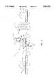
- FIG. 1is a top plan view, shown in schematic, of the apparatus and method of the present invention.
- FIG. 2is a side elevation of a portion of the system shown in FIG. 1 showing the apparatus for coating the four sides of the fibrous object.
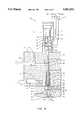
- FIG. 3is a front elevational view (with portions cut away) of a meltblowing die useable in the method and apparatus of the present invention.
- FIG. 4is a longitudinal sectional view of a meltblowing die shown in FIG. 3 with the cutting plane taken generally along the line 4--4 thereof.
- FIGS. 5 and 6are top plan views schematically illustrating the movement of a fibrous batt through the apparatus of FIGS. 1 and 2.
- FIG. 7is a cross-sectional view of a batting coated with a layer of thermoplastic fibers, with the cutting plane along line 7--7 of FIG. 5.
- the present inventionrelates to the complete coating (encapsulation) of a six-sided fibrous object, referred to herein as batting or batt.
- Battings used for insulationare generally formed as six-sided objects, the dimensions of which are such to permit easy installation.
- the fibrous batting Bcomprises four side surfaces 11, 12, 13, and 14 and two end surfaces 15 and 16.
- the dimensions of the batting Bmay vary within a wide range, but generally the length is greater than the width, and the width is greater than the height.
- the lengthbeing the dimension of surfaces 15 and 16 as viewed in FIG. 5, the width being the dimension of surfaces 13 and 14 also viewed in FIG. 5, and the height being the dimension of surfaces 15 and 16 as viewed in FIG. 2.
- the dimensions of batting Bare typically within the following ranges:
- ends 11 and 12are referred to as the top and bottom surfaces, and sides 13 and 14 are referred to as the flanking surfaces.
- End surface 15is the leading end surface and end surface 16 is the back end surface with respect to direction of movement of the batting B through the coating apparatus.
- batt Bis rotated 90° (when viewed from the vantage of FIG. 5) so that after rotation, surfaces 15 and 16 become flanking surfaces with respect to the direction of motion. This position is illustrated as batt B1 in FIG. 5.
- the fibrous batting B used for thermal and acoustic insulationmay be made of a variety of fibrous materials such as rock fibers, glass fibers, slag fibers, wool fibers, and the like.
- the generic name for these fibrous materialsis "mineral fibers”.
- the apparatus line 10 for coating the fibrous battingis illustrated in FIG. 1 and comprises three coating stations: station S-1, station S-2, and station S-3.
- Each coating stationincludes a pair of spaced apart parallel meltblowing dies.
- Station S-1comprises horizontal dies 18 and 19;
- station S-2comprises vertical dies 21 and 22;
- station S-3comprises vertical dies 23 and 24.
- each batting Bpasses sequentially through station S-1, station S-2, and station S-3.
- station S-1applies coating to surfaces 11 and 12
- station S-2coats flanking surfaces 13 and 14, and station S-3 coats end surfaces 15 and 16, whereby batting B is encapsulated.
- the coating line 10includes means for conveying the batting B through each of the stations.
- the meansmay include belt conveyors and/or driven rollers.
- the conveyor for delivering the batting to the line 10includes belt conveyor 26.
- the conveyor for stations S-1 and S-2may comprise a series of elongate closely spaced driven rollers 27.
- the conveying means for stations S-1 and S-2is designated as conveyor surface 29 in FIGS. 1, 2, 5, and 6.
- the conveyor 29extends for a sufficient length after station S-2 for the batting B to clear the dies of station S-2.
- a conveyor surface 32is provided for turning the batting approximately 90° so that the batting passes through station S-3 with the end surfaces 15 and 16 in flanking relationship to the direction of movement, whereby the surfaces pass in confronting relationship to the spaced apart dies 23 and 24, respectively.
- the conveyor surface 32may comprise a plurality of closely spaced rollers positioned at 45° with respect to batting movement.
- the angled rollersare illustrated as 33 in FIG. 1.
- Conveyor 32may also include a plurality of rollers extending perpendicular to the direction of batting movement to move the batting in a linear direction once it has been turned 90°.
- the rollersdefine conveyor surface 35.
- Conveyor 32is also provided with a vertical roller 34 for initiating the turning action on the batting.
- Guide rail 36terminates the turning of the batt and serves to properly align the batt in relation to dies 23 and 24.
- the rollersare each driven, thereby providing the means for moving the batting B through the line 10.
- Conveyor 37is provided to remove the batting B from the apparatus to a collection station (not shown).
- Conveyor 37may be a belt conveyor.
- rollers defining conveyors 29, 32, and 35preferably are of small diameter, in the range of two to three inches, and may be coated with a material such as rubber to promote batt movement.
- the meltblowing dies 18, 19, and 21-24may be of identical construction, except that the length may vary depending upon the dimension of the batting surface to be coated. Although a variety of meltblowing designs may be used, it is preferred that each die be of segmented construction with each segment having an internal valve for controlling polymer flow therethrough. Each die may, but need not, be of the construction described in detail in U.S. Pat. No. 5,145,689, the disclosure of which is incorporated herein by reference.
- the preferred meltblowing dies 18, 19, 21-24 useable in the present inventionthus are of modular construction and capable of intermittent operation. The intermittent operation feature is important because it is necessary to interrupt meltblowing at each coating station when no batting B is disposed therein (i.e. between dies).
- the dies used in the present inventionbe self-cleaning when shut down. Meltblowing dies that are not self-cleaning could become plugged by polymer setting up in the die orifices and passages during shut down periods.
- the die assembly disclosed in U.S. Pat. No. 5,145,689is particularly suited for use in the present invention because it is of modular construction, and features intermittent and self-cleaning operation. Since the die assembly is disclosed in detail in said U.S. Pat. No. 5,145,689, it will be described only generally herein.
- dies 18, 19, and 21-24may be of the same construction, except for the die length.
- the die 18comprises a body 41, meltblowing modules 40A-40D, and die tip assembly 43.
- a valve actuator 42A-42Dis provided for each module.
- the length of the die body 41 and die tip 43, and the number of units 40A-40D and associated valve actuators 42A-42Dmay be varied to provide the coating of the desired dimension.
- die body 41has formed therein intersecting polymer passages 44 and 45. Passage 44 connects to polymer feed line 46 through header manifold 47, and passage 45 is vertically aligned with valve actuator 42 and die tip assembly 43.
- Polymer feed line 46is preferably a flexible hose.
- passage 45The lower end of passage 45 is threaded for receiving insert 48 having port 49 formed therein.
- the inlet to port 49is shaped to provide a valve seat at surface 50.
- the polymer passage of each unitis fed by a balancing header 51 formed in manifold 47 in the form of a coat hanger spanning the inlets of passages 44 of each unit 40A-40D.
- the polymer flow through the body 41is from line 46, through balancing header 51, through flow passages 44 and 45 of each unit in parallel flow, discharging through port 49 of each unit.
- the bottom side of die body 41has a machined out section which defines elongate air chamber 52.
- the circular inserts 48 of each unit mounted on the die body 41separate the air chamber 52 from polymer flow passage 45.
- the air chamber 52is continuous throughout the die body 41 and surrounds the inserts 48 of all the units. Sealing means such as o-rings 55 are provided to seal air chamber 52 and polymer passage 45.
- the air passages 53are distributed along the length of the die body 41 to provide generally uniform flow of air into chamber 52 at spaced locations.
- Airis fed by header 54 which may be formed in manifold 47. Hot air is delivered to the air passage 54 by flexible hose 56. The air is heated using in-line electric or gas heaters (now shown). Air thus flows from air line 56, through air header 54, in parallel flow through air passages 53, and into air chamber 52.
- the die tip assembly 43is mounted to the underside of the die body 41 and covers air chamber 52.
- This assemblycomprises a stack up of three members: a transfer plate 57, a die tip 58, and air plates 59 and 60.
- Members 57, 58, 59, and 60each extend substantially the full length of the die body 41 and in assembled relation are secured thereto by bolts (not shown).
- Pairs of air passages 61 and 62extend through the transfer plate 57 and the die tip 58.
- air passages 60 and 61comprise a plurality of passages equispaced along the length of the die for conducting air in parallel flow from chamber 52 into the die assembly.
- the air passagesdischarge into elongate air slits 63 and 64 defined by the confronting surfaces of the die tip 58 and air plates 59 and 60.
- the slits 63 and 64converge as illustrated in FIG. 4 so that air passing therethrough forms a pair of air sheets which converge a short distance from the die discharge.
- a central polymer passage 66 extending through the transfer plate 57is aligned with port 49 and polymer passage 45 of the die body 41.
- the confronting surfaces of the transfer plate 57 and the die tip 58have channels formed therein defining elongate end-to-end chambers 67 (67A-67D in FIG. 3).
- Each chambere.g. 67A
- Each chamberextends substantially the width of its associated unit (e.g. 40A), but is separated from its adjacent chamber (e.g. 67B) or chambers.
- the chambers 67 of each unitare longitudinally aligned and in combination extend substantially the entire length of the transfer plate 57.
- Extending from chamber 67are a plurality of polymer flow passages 68 terminating in orifices 69 at the apex of the die tip 58.
- the orificesare referenced as 69A-69D in FIG. 3.
- the ends of each chamber 67are preferably closely spaced apart so that the orifice spacing along the die tip are equally spaced substantially along the entire die tip length.
- the air sheetsimpart a drag force on the filaments which draws the filaments down to microsize diameters.
- Each unit 40A-40D along themay have a length of 3/4" to 4".
- the orifice spacingmay range from 5 to 40 orifices per inch.
- the total number of units in a particular diewill depend on the surface to be coated. For short dimensions, from 2 to 10 units may be satisfactory; for long dimensions, from 10 to 50 units may be required.
- die tip assembly 43in relation to die body 41, and the configuration and number of air passages, polymer passages and chambers, may be as described in U.S. Pat. No. 5,145,689.
- the modular valve actuators 42A-42Dimpart intermittent flow of polymer through the die body 41 and the die tip assembly for each unit. The intermittent is important for shutting off the dies while the batt is positioned between coating stations.
- the valve actuators 42A-42Dmay also be independently programmed to interrupt or initiate polymer flow through the meltblowing modules to produce a coating of varying width. For example, interrupting the flow through end modules 40A and 40D, while units 40B and 40C continue to operate, will result in a coating having only about half the width of that produced when all four units 40A-40D are in operation. This feature may be useful for coating batts of various sizes with the same coating apparatus 10.
- the method for actuating each of the valvescomprises pneumatic piston 72 located within a cylinder defined by housing 70.
- the piston and the walls of the housingdefine lower air chamber 77 and upper air chamber 78.
- a fluid sealis established across piston 72 using o-ring 83.
- a valve stem 74 positioned in passage 45has its upper end secured to piston 72 and moves therewith. The stem 74 extends downwardly into body passage 45 terminating at lower tapered end 76.
- the valveis actuated by controls 71.
- the control 71may be a solenoid, 4-way, two-position valve fed by an air supply. Electrical controls activate and deactivate the solenoid of the control valve 71.
- the solenoidis energized causing air flow from control valve 71 through line 73 into piston assembly lower chamber 77, while air in the upper chamber 78 exhausts through line 75 and control valve 71. Air pressure in chamber 77 causes piston 72 and the stem 74 to move upwardly. Stationary rod 79 limits the upward stroke of the piston and stem.
- valve module 42In the normal deactivated position of the valve module 42, spring 81 forces piston 72 and stem 74 downwardly until stem tip 76 seats on the valve seat 50 of port 49, thereby shutting off the polymer flow therethrough.
- Energization of the control valve 71causes piston 72 and stem 74 to move upwardly opening port 49, permitting polymer to flow from passage 45 to die tip assembly 43.
- o-ringsare provided as at 82.
- each die 18, 19, and 21-24hot air is continuously delivered to each die, while polymer melt is selectively delivered to each unit of the die by selectively actuating the control valves 71A-71D (not shown) of each unit 40A-40D.
- the orifices of the activated unitse.g. orifices 69A, 69B, 69C, and 69D shown in FIG. 3
- converging sheets of air discharging from slits 63 and 64FIG. 4
- contact the filaments 65 and stretch the filaments to microsizee.g. 1 to 20 microns).
- the filaments 65are deposited on the surface of the batt B in a random manner forming an entangled web of filaments thereon (i.e. nonwoven web) shown as coating 85 in FIG. 3.
- the integrity of the coatingis provided mainly by mechanical entanglement of the fibers.
- the amount of web deposited on each batt surfacemay range from 5 to 20 gr./m 2 , preferably 8 to 12 gr./m 2 .
- the filamentsfrequently are referred to as fibers or strands. These terms are used interchangeably herein to describe meltblown materials.
- the coating 85has been found to have excellent adhesion to fibrous batt B.
- the adhesionis due to a number of factors including interfiber entanglement between the coating and fibers of the batt cohesive sticking since the coating is applied to the batt in the molten or semi-molten state, and frictional forces.
- die 18is positioned above conveyor surface 29 to coat the top side 11 of the batt B, and die 19 is positioned below the conveyor surface 29 to coat the bottom surface 12 of the batt B. Note that there are no rollers 27 immediately above die 19.
- the coatings produced by dies 18 and 19are illustrated as coatings 86 and 87, respectively, in FIGS. 2 and 7.
- dies 21 and 22similarly coat the uncoated sides 13 and 14 of the batt B with a nonwoven web.
- FIG. 5depicts these coatings as 88 and 89. Note that there is an overlap of the coatings at the four edges (see FIG. 7) to ensure complete coverage and good adhesion by the nonwoven webs.
- the batthas been turned 90° so that end surfaces 16 and 17 occupy the flanks of the batt B. Passage of the batt B in this position through the dies 23 and 24 of station S-3, places the side surfaces in confronting relationship to the filaments discharged from the dies, completely coating and encapsulating the batt B with a nonwoven web. As shown in FIGS. 5 and 7, coatings 90 and 91 are applied to surfaces 15 and 16, respectively. As best seen in FIG. 7, dies 23 and 24 are positioned to provide a slight overlap at the edges, as at 92, to ensure complete coating and good adhesion.
- the nonwoven coatings 86-91adhere to the batt and in the overlapped areas by mechanical entanglement without the need of adhesives which could alter the insulation and/or permeability properties of the batts.
- each die from the battwill typically be in the order of 6 to 9 inches.
- the structure for mounting the dies in the proper positioncan be by any frame or mechanical support means. For clarity, the mounting structure has not been shown. However, support members 93 are shown bolted to dies 21 and 22. Each member 93 extends transversely across the conveyor surface 29. The dies thus can be moved laterally to provide the desired spacing. Similar mounting members can be provided on dies 23 and 24 to permit lateral adjustment; likewise, vertical mounting members can be provided on dies 18 and 19 to permit vertical adjustment of dies 18 and 19.
- the polymer used to coat the battingmay include a wide range of polymers used in meltblowing to form nonwoven webs. These can be any one of the variety of thermoplastics used in meltblowing operations.
- the typical meltblowing web forming resinsinclude a wide range of polyolefins such as propylene and ethylene homopolymers and copolymers. Specific thermoplastics include ethylene acrylic copolymers, nylon polyamides, polyesters, EMA, polystyrene poly(methyl methacrylate), silicone sulfide, and poly(ethylene terephthalate), and blends of the above.
- the preferred resinis polypropylene. The above list is not intended to be limiting, as new and improved meltblowing thermoplastic resins continue to be developed.
- the polymer meltmay be delivered to each die by conventional extruders or a polymer melt delivery system described in U.S. Pat. No. 5,061,170, the disclosure of which is incorporated herein by reference.
- the hot airmay be provided by use of conventional furnaces or electric heaters. The temperature of the polymer melt and the air are exemplified in the Example below.
- FIGS. 2, 5, and 6illustrate the dispositions of the batt B along line 10, through coating stations S-1, S-2, and S-3.
- the coating processwill be carried out automatically and will process individual batts at frequent time intervals.
- batt B1is passing through station S-3
- batt B2has passed station S-2 and is in the process of being turned 90°
- batt B3is being conveyed into station S-1.
- Conveyor 26transports the batt B onto conveyor 29 defined by rollers 27 (see FIG. 2).
- the batt Bupon passing over die 19 actuates operation of that die wherein side surface 12 is coated with coating 87. Further movement of the batt brings it directly under die 18 which is automatically actuated to apply coating 86 to surface 11 of the batt B. As the batt B clears dies 19 and 18, each die automatically shuts off.
- die 22Upon entering station S-2, die 22 is actuated coating side 14 with coating 89 as shown in FIG. 6. Further movement of the batt in station S-2 activates die 21 which coats side surface 13 with layer 88. Dies 21 and 22 also are automatically shut off following the coating step. Further movement of the batt along roller conveyor 29 brings the leading surface 15 into contact with continuously rotating roller 34.
- FIG. 5illustrates batt B2 in the process of being turned.
- the battis moved on conveyor 32 until it contacts guide rail or wall 36 placing it in the position of batt B2 in FIG. 6.
- the rollers of conveyor 35move the batt B2 into confronting relationship with dies 23 and 24 where the dies automatically coat end surfaces 15 and 16 with coatings 90 and 91.
- the battis thus completely encapsulated in the nonwoven web, which overlaps at the edges of the batt as illustrated in FIG. 7.
- the battis moved onto conveyor 37 where it is removed from the line to a collection area.
- Actuating for automatically controlling the on/off operation of the dies in timed relation to the movement of the battscan be accomplished using optical sensors (not shown).
- a typical configurationwould comprise a light or light beam source placed on one side of the conveyor line and focused on a light detecting sensor on the opposite side of the conveyor.
- the sensormay be any number of sensors commercially available, such as photodiodes.
- the light source and sensorwill be positioned in front of the die to be actuated so that when a batt moves between the source and the sensor the light transmitted therebetween will be interrupted thereby activating the sensor.
- the sensorwill produce an electrical signal which may be wired to polymer valve actuators 42 for turning the die on.
- a six-sided battwas coated with polypropylene meltblown web using the line described above. Details of the batt and line were as follows:
- the battwas moved through station S-1 with the long dimension (1200 mm) extended transversely across the conveyors (major axis perpendicular to the direction of batt movement), wherein the top and bottom surfaces (1200 mm ⁇ 200 mm) were coated.
- the battwas moved through station S-2 wherein the side surfaces (200 mm ⁇ 90 mm) were coated.
- the battwas then turned 90° and moved through station S-3 with the remaining two uncoated surfaces positioned in flanking relationship with the direction of batt movement.
- the final two surfaces(1200 mm ⁇ 90 mm) were coated.
- Batt movement through each stationwas approximately 20 meters/min. The entire coating process required less than one minute.
- the coated battwas characterized by a complete coating (encapsulation) leaving no part of the fibrous batt exposed.
- the coatingwas generally uniform, except in the overlapped edges, and provided a durable coating.
- the battcould be handled easily without disintegration or disruption of the encapsulated fibrous material.
- the Exampledemonstrates the utility of the present invention in providing a durable coating which completely encapsulates the six-sided batt with thermoplastic meltblown fibers.
Landscapes
- Engineering & Computer Science (AREA)
- Physics & Mathematics (AREA)
- Architecture (AREA)
- Acoustics & Sound (AREA)
- Electromagnetism (AREA)
- Civil Engineering (AREA)
- Structural Engineering (AREA)
- Textile Engineering (AREA)
- Nonwoven Fabrics (AREA)
Abstract
Description
______________________________________ Range (mm)______________________________________length 800-2000width 100-400height 50-150______________________________________
______________________________________Batt: Material: Mineral, wool and slag Dimensions: length/width/height: 1200 mm/200 mm/90/mm Use: Building insulationDies: Station S-1 Station S-2 Station S-3Each die 122 23 3length (cm)Units (no.) 32 9 9Unit 3.5 3.5 3.5length (cm)Orifice 25 25 25(no./inc.)Orifice 0.020.sup.4 0.020.sup.4 0.020.sup.4diameter(in.)Operating ConditionsPolymer* Polypropylene 800 MFRDie Temperature 250° C.Air Temperature 260° C.Polymer Flow Rate 0.2 grams/orifice/min.Air Flow Rate 5 SCFM/inchCoating 10 grams/m.sup.2Average 5-10 micronsFiber Diameter______________________________________
Claims (12)
Priority Applications (2)
| Application Number | Priority Date | Filing Date | Title |
|---|---|---|---|
| US08/425,973US5501872A (en) | 1995-04-19 | 1995-04-19 | Method and apparatus for coating a six-sided fibrous batting |
| PCT/US1996/005437WO1996033305A1 (en) | 1995-04-19 | 1996-04-19 | Method and apparatus for coating a six-sided fibrous batting |
Applications Claiming Priority (1)
| Application Number | Priority Date | Filing Date | Title |
|---|---|---|---|
| US08/425,973US5501872A (en) | 1995-04-19 | 1995-04-19 | Method and apparatus for coating a six-sided fibrous batting |
Publications (1)
| Publication Number | Publication Date |
|---|---|
| US5501872Atrue US5501872A (en) | 1996-03-26 |
Family
ID=23688779
Family Applications (1)
| Application Number | Title | Priority Date | Filing Date |
|---|---|---|---|
| US08/425,973Expired - Fee RelatedUS5501872A (en) | 1995-04-19 | 1995-04-19 | Method and apparatus for coating a six-sided fibrous batting |
Country Status (2)
| Country | Link |
|---|---|
| US (1) | US5501872A (en) |
| WO (1) | WO1996033305A1 (en) |
Cited By (29)
| Publication number | Priority date | Publication date | Assignee | Title |
|---|---|---|---|---|
| US5876529A (en)* | 1997-11-24 | 1999-03-02 | Owens Corning Fiberglas Technology, Inc. | Method of forming a pack of organic and mineral fibers |
| US5900206A (en)* | 1997-11-24 | 1999-05-04 | Owens Corning Fiberglas Technology, Inc. | Method of making a fibrous pack |
| US5983586A (en)* | 1997-11-24 | 1999-11-16 | Owens Corning Fiberglas Technology, Inc. | Fibrous insulation having integrated mineral fibers and organic fibers, and building structures insulated with such fibrous insulation |
| US6113818A (en)* | 1997-11-24 | 2000-09-05 | Owens Corning Fiberglas Technology, Inc. | Method and apparatus for integrating organic fibers with mineral fibers |
| US6135747A (en)* | 1996-07-22 | 2000-10-24 | Guardian Fiberglass, Inc. | Apparatus for making mineral fiber insulation batt impregnated with extruded synthetic fibers |
| US6203646B1 (en)* | 1992-02-28 | 2001-03-20 | Rockwool International A/S | Process for preparing a mineral fibre element comprising a surface coating |
| US6391131B1 (en)* | 1997-05-29 | 2002-05-21 | Clark-Schwebel Tech-Fab Company | Method of making glass fiber facing sheet |
| US6436471B1 (en) | 1997-05-28 | 2002-08-20 | Rockwool International A/S | Plant and process for coating a multi-sided mineral fiber element |
| WO2002053819A3 (en)* | 2001-01-08 | 2002-10-03 | Rockwool Int | Insulating element |
| US20040023014A1 (en)* | 2002-08-05 | 2004-02-05 | Williamson Bruce Scott | Acoustical insulation material containing fine thermoplastic fibers |
| US20040037931A1 (en)* | 2001-08-21 | 2004-02-26 | United States Bakery, Inc. | Method and apparatus for applying dry toppings to baked goods |
| US20040118511A1 (en)* | 2002-12-24 | 2004-06-24 | Daojie Dong | Method and apparatus for soft skin encapsulation |
| US20040118506A1 (en)* | 2002-12-24 | 2004-06-24 | Daojie Dong | Method and apparatus for melt-blown fiber encapsulation |
| WO2004061184A1 (en)* | 2002-12-20 | 2004-07-22 | Kimberly-Clark Worldwide, Inc. | Encased insulation article |
| US20040172050A1 (en)* | 1995-02-24 | 2004-09-02 | Bolduc Lee R. | Surgical clips and methods for tissue approximation |
| US20040217507A1 (en)* | 2001-09-06 | 2004-11-04 | Alain Yang | Continuous process for duct liner production with air laid process and on-line coating |
| US20050026527A1 (en)* | 2002-08-05 | 2005-02-03 | Schmidt Richard John | Nonwoven containing acoustical insulation laminate |
| US20050090783A1 (en)* | 2003-10-27 | 2005-04-28 | Sibbitt Wilmer L.Jr. | Colorful shielded reciprocating butterfly needle |
| US20050098255A1 (en)* | 2003-11-06 | 2005-05-12 | Lembo Michael J. | Insulation product having nonwoven facing and process for making same |
| US20050126677A1 (en)* | 2003-12-10 | 2005-06-16 | Daojie Dong | Apparatus and method for fiber batt encapsulation |
| US20060078699A1 (en)* | 2004-10-12 | 2006-04-13 | Mankell Kurt O | Insulation board with weather and puncture resistant facing and method of manufacturing the same |
| US20070062887A1 (en)* | 2005-09-20 | 2007-03-22 | Schwandt Brian W | Space optimized coalescer |
| US20070062886A1 (en)* | 2005-09-20 | 2007-03-22 | Rego Eric J | Reduced pressure drop coalescer |
| US20070107399A1 (en)* | 2005-11-14 | 2007-05-17 | Schwandt Brian W | Variable coalescer |
| US20070131235A1 (en)* | 2005-11-14 | 2007-06-14 | Janikowski Eric A | Method and apparatus for making filter element, including multi-characteristic filter element |
| US20080145681A1 (en)* | 2003-11-06 | 2008-06-19 | Toas Murray S | Reinforced Humidity Adaptive Vapor Retarding Film and Method of Manufacture |
| US20090126324A1 (en)* | 2007-11-15 | 2009-05-21 | Smith Guillermo A | Authorized Filter Servicing and Replacement |
| US7828869B1 (en) | 2005-09-20 | 2010-11-09 | Cummins Filtration Ip, Inc. | Space-effective filter element |
| CN108126848A (en)* | 2018-02-05 | 2018-06-08 | 鲁忠华 | A kind of square steel antirust paint smoothens device |
Families Citing this family (1)
| Publication number | Priority date | Publication date | Assignee | Title |
|---|---|---|---|---|
| AU7520098A (en)* | 1997-05-28 | 1998-12-30 | Rockwool International A/S | Plant and process for producing a coated mineral fibre element |
Citations (3)
| Publication number | Priority date | Publication date | Assignee | Title |
|---|---|---|---|---|
| US4098629A (en)* | 1976-04-05 | 1978-07-04 | Allen Industries, Inc. | Process for making sound insulation components |
| US5061170A (en)* | 1989-12-08 | 1991-10-29 | Exxon Chemical Patents Inc. | Apparatus for delivering molten polymer to an extrusion |
| US5145689A (en)* | 1990-10-17 | 1992-09-08 | Exxon Chemical Patents Inc. | Meltblowing die |
Family Cites Families (2)
| Publication number | Priority date | Publication date | Assignee | Title |
|---|---|---|---|---|
| US2802561A (en)* | 1952-08-18 | 1957-08-13 | Ransburg Electro Coating Corp | Apparatus for indexing articles |
| DK26792D0 (en)* | 1992-02-28 | 1992-02-28 | Rockwool Int | METHOD FOR MANUFACTURING MINERAL FIBER PRODUCTS |
- 1995
- 1995-04-19USUS08/425,973patent/US5501872A/ennot_activeExpired - Fee Related
- 1996
- 1996-04-19WOPCT/US1996/005437patent/WO1996033305A1/enactiveApplication Filing
Patent Citations (5)
| Publication number | Priority date | Publication date | Assignee | Title |
|---|---|---|---|---|
| US4098629A (en)* | 1976-04-05 | 1978-07-04 | Allen Industries, Inc. | Process for making sound insulation components |
| US5061170A (en)* | 1989-12-08 | 1991-10-29 | Exxon Chemical Patents Inc. | Apparatus for delivering molten polymer to an extrusion |
| US5145689A (en)* | 1990-10-17 | 1992-09-08 | Exxon Chemical Patents Inc. | Meltblowing die |
| US5421941A (en)* | 1990-10-17 | 1995-06-06 | J & M Laboratories, Inc. | Method of applying an adhesive |
| US5445509A (en)* | 1990-10-17 | 1995-08-29 | J & M Laboratories, Inc. | Meltblowing die |
Cited By (44)
| Publication number | Priority date | Publication date | Assignee | Title |
|---|---|---|---|---|
| US6203646B1 (en)* | 1992-02-28 | 2001-03-20 | Rockwool International A/S | Process for preparing a mineral fibre element comprising a surface coating |
| US20040172050A1 (en)* | 1995-02-24 | 2004-09-02 | Bolduc Lee R. | Surgical clips and methods for tissue approximation |
| US6135747A (en)* | 1996-07-22 | 2000-10-24 | Guardian Fiberglass, Inc. | Apparatus for making mineral fiber insulation batt impregnated with extruded synthetic fibers |
| US6436471B1 (en) | 1997-05-28 | 2002-08-20 | Rockwool International A/S | Plant and process for coating a multi-sided mineral fiber element |
| US6391131B1 (en)* | 1997-05-29 | 2002-05-21 | Clark-Schwebel Tech-Fab Company | Method of making glass fiber facing sheet |
| US5876529A (en)* | 1997-11-24 | 1999-03-02 | Owens Corning Fiberglas Technology, Inc. | Method of forming a pack of organic and mineral fibers |
| US6113818A (en)* | 1997-11-24 | 2000-09-05 | Owens Corning Fiberglas Technology, Inc. | Method and apparatus for integrating organic fibers with mineral fibers |
| US5983586A (en)* | 1997-11-24 | 1999-11-16 | Owens Corning Fiberglas Technology, Inc. | Fibrous insulation having integrated mineral fibers and organic fibers, and building structures insulated with such fibrous insulation |
| US5900206A (en)* | 1997-11-24 | 1999-05-04 | Owens Corning Fiberglas Technology, Inc. | Method of making a fibrous pack |
| WO2002053819A3 (en)* | 2001-01-08 | 2002-10-03 | Rockwool Int | Insulating element |
| US20040037931A1 (en)* | 2001-08-21 | 2004-02-26 | United States Bakery, Inc. | Method and apparatus for applying dry toppings to baked goods |
| US7815967B2 (en)* | 2001-09-06 | 2010-10-19 | Alain Yang | Continuous process for duct liner production with air laid process and on-line coating |
| US20040217507A1 (en)* | 2001-09-06 | 2004-11-04 | Alain Yang | Continuous process for duct liner production with air laid process and on-line coating |
| US20040023014A1 (en)* | 2002-08-05 | 2004-02-05 | Williamson Bruce Scott | Acoustical insulation material containing fine thermoplastic fibers |
| US6893711B2 (en) | 2002-08-05 | 2005-05-17 | Kimberly-Clark Worldwide, Inc. | Acoustical insulation material containing fine thermoplastic fibers |
| US20050026527A1 (en)* | 2002-08-05 | 2005-02-03 | Schmidt Richard John | Nonwoven containing acoustical insulation laminate |
| WO2004061184A1 (en)* | 2002-12-20 | 2004-07-22 | Kimberly-Clark Worldwide, Inc. | Encased insulation article |
| US6878427B2 (en) | 2002-12-20 | 2005-04-12 | Kimberly Clark Worldwide, Inc. | Encased insulation article |
| US6905563B2 (en) | 2002-12-24 | 2005-06-14 | Owens Corning Fiberglas Technology, Inc. | Method and apparatus for melt-blown fiber encapsulation |
| US20040118506A1 (en)* | 2002-12-24 | 2004-06-24 | Daojie Dong | Method and apparatus for melt-blown fiber encapsulation |
| US7060155B2 (en) | 2002-12-24 | 2006-06-13 | Owens Corning Fiberglas Technology, Inc. | Method and apparatus for soft skin encapsulation |
| US20040118511A1 (en)* | 2002-12-24 | 2004-06-24 | Daojie Dong | Method and apparatus for soft skin encapsulation |
| US20050090783A1 (en)* | 2003-10-27 | 2005-04-28 | Sibbitt Wilmer L.Jr. | Colorful shielded reciprocating butterfly needle |
| US20080145681A1 (en)* | 2003-11-06 | 2008-06-19 | Toas Murray S | Reinforced Humidity Adaptive Vapor Retarding Film and Method of Manufacture |
| WO2005046985A1 (en)* | 2003-11-06 | 2005-05-26 | Certainteed Corporation | Insulation product having nonwoven facing and process for making same |
| US20050098255A1 (en)* | 2003-11-06 | 2005-05-12 | Lembo Michael J. | Insulation product having nonwoven facing and process for making same |
| US20050126677A1 (en)* | 2003-12-10 | 2005-06-16 | Daojie Dong | Apparatus and method for fiber batt encapsulation |
| WO2005061809A1 (en)* | 2003-12-10 | 2005-07-07 | Owens Corning | Apparatus and method for fiber batt encapsulation |
| US7052563B2 (en) | 2003-12-10 | 2006-05-30 | Owens Corning Fiberglas Technology, Inc. | Apparatus and method for fiber batt encapsulation |
| US20060078699A1 (en)* | 2004-10-12 | 2006-04-13 | Mankell Kurt O | Insulation board with weather and puncture resistant facing and method of manufacturing the same |
| US20110094382A1 (en)* | 2005-09-20 | 2011-04-28 | Cummins Filtration Ip, Inc. | Reduced pressure drop coalescer |
| US8114183B2 (en) | 2005-09-20 | 2012-02-14 | Cummins Filtration Ip Inc. | Space optimized coalescer |
| US8545707B2 (en) | 2005-09-20 | 2013-10-01 | Cummins Filtration Ip, Inc. | Reduced pressure drop coalescer |
| US20070062887A1 (en)* | 2005-09-20 | 2007-03-22 | Schwandt Brian W | Space optimized coalescer |
| US7828869B1 (en) | 2005-09-20 | 2010-11-09 | Cummins Filtration Ip, Inc. | Space-effective filter element |
| US20070062886A1 (en)* | 2005-09-20 | 2007-03-22 | Rego Eric J | Reduced pressure drop coalescer |
| US7674425B2 (en) | 2005-11-14 | 2010-03-09 | Fleetguard, Inc. | Variable coalescer |
| US20070131235A1 (en)* | 2005-11-14 | 2007-06-14 | Janikowski Eric A | Method and apparatus for making filter element, including multi-characteristic filter element |
| US8231752B2 (en) | 2005-11-14 | 2012-07-31 | Cummins Filtration Ip Inc. | Method and apparatus for making filter element, including multi-characteristic filter element |
| US20070107399A1 (en)* | 2005-11-14 | 2007-05-17 | Schwandt Brian W | Variable coalescer |
| US20090126324A1 (en)* | 2007-11-15 | 2009-05-21 | Smith Guillermo A | Authorized Filter Servicing and Replacement |
| US7959714B2 (en) | 2007-11-15 | 2011-06-14 | Cummins Filtration Ip, Inc. | Authorized filter servicing and replacement |
| US8114182B2 (en) | 2007-11-15 | 2012-02-14 | Cummins Filtration Ip, Inc. | Authorized filter servicing and replacement |
| CN108126848A (en)* | 2018-02-05 | 2018-06-08 | 鲁忠华 | A kind of square steel antirust paint smoothens device |
Also Published As
| Publication number | Publication date |
|---|---|
| WO1996033305A1 (en) | 1996-10-24 |
Similar Documents
| Publication | Publication Date | Title |
|---|---|---|
| US5501872A (en) | Method and apparatus for coating a six-sided fibrous batting | |
| WO1996033305A9 (en) | Method and apparatus for coating a six-sided fibrous batting | |
| EP0553237B1 (en) | Melt-blowing die | |
| CN1102079C (en) | Segmented die for applying hot melt adhesives or other polymer melts | |
| US6936125B2 (en) | Method of applying a continuous adhesive filament to an elastic strand with discrete bond points and articles manufactured by the method | |
| US5728219A (en) | Modular die for applying adhesives | |
| US6436471B1 (en) | Plant and process for coating a multi-sided mineral fiber element | |
| CN1973074B (en) | Machine for production of non-woven fabric, adjustment procedure for the same and non-woven fabric produced thus | |
| US5900206A (en) | Method of making a fibrous pack | |
| EP1270770A3 (en) | Apparatus for the manufacture of nonwoven webs and laminates | |
| EP0173333B1 (en) | Extrusion process and an extrusion die with a central air jet | |
| FI106368B (en) | Process for manufacturing a mineral fiber element and apparatus for carrying out the process | |
| EP0866152B1 (en) | Meltblowing apparatus and process | |
| US3970035A (en) | Powder deposition system | |
| US20070216059A1 (en) | Apparatus and methods for producing split spunbond filaments | |
| US5605556A (en) | Linear ramped air lapper for fibrous material | |
| CZ415699A3 (en) | Process and apparatus for application coating to multiple-side elements of mineral wool | |
| EP0987352A2 (en) | Modular meltblowing die | |
| WO1998054388A1 (en) | Plant and process for producing a coated mineral fibre element | |
| WO1996030577A1 (en) | High-frequency air lapper for fibrous material | |
| MXPA97004686A (en) | Method for the elaboration of fibers of mineral material with organic material | |
| CZ415499A3 (en) | Process and apparatus for producing coated elements of mineral wool | |
| MXPA00005072A (en) | Method of making a fibrous pack |
Legal Events
| Date | Code | Title | Description |
|---|---|---|---|
| AS | Assignment | Owner name:EXXON CHEMICAL PATENTS INC., DELAWARE Free format text:ASSIGNMENT OF ASSIGNORS INTEREST;ASSIGNORS:ALLEN, MARTIN A.;FETCKO, JOHN T.;REEL/FRAME:007862/0684 Effective date:19960319 | |
| AS | Assignment | Owner name:GEORGIA FIRST BANK, GEORGIA Free format text:ASSIGNMENT OF ASSIGNORS INTEREST;ASSIGNOR:J AND M LABORATORIES, INC.;REEL/FRAME:008773/0381 Effective date:19970905 | |
| AS | Assignment | Owner name:J&M LABORATORIES INC., GEORGIA Free format text:ASSIGNMENT OF ASSIGNORS INTEREST;ASSIGNOR:EXXON CHEMICAL PATENTS INC.;REEL/FRAME:009075/0379 Effective date:19980226 | |
| AS | Assignment | Owner name:PREMIER BANK, A GEORGIA BANKING CORPORATION, GEORG Free format text:ASSIGNMENT OF ASSIGNORS INTEREST;ASSIGNOR:J AND M LABORATORIES, INC., A CORP. OF GEORGIA;REEL/FRAME:009605/0466 Effective date:19980811 | |
| FEPP | Fee payment procedure | Free format text:PAYOR NUMBER ASSIGNED (ORIGINAL EVENT CODE: ASPN); ENTITY STATUS OF PATENT OWNER: LARGE ENTITY | |
| AS | Assignment | Owner name:NORDSON CORPORATION, OHIO Free format text:ASSIGNMENT OF ASSIGNORS INTEREST;ASSIGNOR:J & M LABORATORIES, INC.;REEL/FRAME:009798/0275 Effective date:19990301 | |
| FPAY | Fee payment | Year of fee payment:4 | |
| FPAY | Fee payment | Year of fee payment:8 | |
| REMI | Maintenance fee reminder mailed | ||
| LAPS | Lapse for failure to pay maintenance fees | ||
| STCH | Information on status: patent discontinuation | Free format text:PATENT EXPIRED DUE TO NONPAYMENT OF MAINTENANCE FEES UNDER 37 CFR 1.362 | |
| FP | Lapsed due to failure to pay maintenance fee | Effective date:20080326 |