US5501793A - Traveling water screen including improved basket - Google Patents
Traveling water screen including improved basketDownload PDFInfo
- Publication number
- US5501793A US5501793AUS08/221,368US22136894AUS5501793AUS 5501793 AUS5501793 AUS 5501793AUS 22136894 AUS22136894 AUS 22136894AUS 5501793 AUS5501793 AUS 5501793A
- Authority
- US
- United States
- Prior art keywords
- lip beam
- basket
- water screen
- water
- upstream
- Prior art date
- Legal status (The legal status is an assumption and is not a legal conclusion. Google has not performed a legal analysis and makes no representation as to the accuracy of the status listed.)
- Expired - Lifetime
Links
- XLYOFNOQVPJJNP-UHFFFAOYSA-NwaterSubstancesOXLYOFNOQVPJJNP-UHFFFAOYSA-N0.000titleclaimsabstractdescription203
- 238000011144upstream manufacturingMethods0.000claimsabstractdescription92
- 241000251468ActinopterygiiSpecies0.000claimsdescription23
- 238000007789sealingMethods0.000claimsdescription15
- 238000012216screeningMethods0.000claimsdescription11
- 239000000463materialSubstances0.000claimsdescription5
- 239000002131composite materialSubstances0.000claimsdescription4
- 238000011010flushing procedureMethods0.000claims4
- 239000011152fibreglassSubstances0.000description3
- 238000005452bendingMethods0.000description2
- 239000003638chemical reducing agentSubstances0.000description2
- 238000010276constructionMethods0.000description2
- 238000001816coolingMethods0.000description1
- 239000000498cooling waterSubstances0.000description1
- 230000007797corrosionEffects0.000description1
- 238000005260corrosionMethods0.000description1
- HQQADJVZYDDRJT-UHFFFAOYSA-Nethene;prop-1-eneChemical groupC=C.CC=CHQQADJVZYDDRJT-UHFFFAOYSA-N0.000description1
- 229920001084poly(chloroprene)Polymers0.000description1
- 239000002990reinforced plasticSubstances0.000description1
- 239000012858resilient materialSubstances0.000description1
Images
Classifications
- E—FIXED CONSTRUCTIONS
- E02—HYDRAULIC ENGINEERING; FOUNDATIONS; SOIL SHIFTING
- E02B—HYDRAULIC ENGINEERING
- E02B1/00—Equipment or apparatus for, or methods of, general hydraulic engineering, e.g. protection of constructions against ice-strains
- E02B1/006—Arresting, diverting or chasing away fish in water-courses or water intake ducts, seas or lakes, e.g. fish barrages, deterrent devices ; Devices for cleaning fish barriers
- B—PERFORMING OPERATIONS; TRANSPORTING
- B01—PHYSICAL OR CHEMICAL PROCESSES OR APPARATUS IN GENERAL
- B01D—SEPARATION
- B01D33/00—Filters with filtering elements which move during the filtering operation
- B01D33/333—Filters with filtering elements which move during the filtering operation with individual filtering elements moving along a closed path
- E—FIXED CONSTRUCTIONS
- E02—HYDRAULIC ENGINEERING; FOUNDATIONS; SOIL SHIFTING
- E02B—HYDRAULIC ENGINEERING
- E02B8/00—Details of barrages or weirs ; Energy dissipating devices carried by lock or dry-dock gates
- E02B8/02—Sediment base gates; Sand sluices; Structures for retaining arresting waterborne material
- E02B8/023—Arresting devices for waterborne materials
- E02B8/026—Cleaning devices
Definitions
- the inventionrelates to traveling water screens for screening debris and fish from water, and more particularly to an improved basket for a traveling water screen.
- Traveling water screenshave been used for many years in applications in which it is desired to screen debris and fish from large volumes of water.
- a typical applicationis in an industrial facility or power plant which requires a large volume of cooling water.
- water for this purposeis taken from a river or lake through an inlet water channel. Debris and fish enter the channel with the water flowing into channel and must be screened out of the water to prevent debris from clogging the condenser tubes and to prevent the fish from being killed by heat and impingement on the condenser tubes and other parts of the cooling system.
- U.S. Pat. Nos. 4,582,601, 4,360,426 and 3,868,324illustrate traveling water screens.
- a traveling water screentypically includes an upright frame having a pair of spaced vertical support members. The support members are mounted adjacent the opposed sides of the water inlet channel, such that water flowing through the channel cannot flow around the sides of the water screen.
- the frameincludes a boot portion adjacent the bottom of the channel and a head portion anchored in a horizontal shelf above the water in the channel.
- a foot shaftis supported for rotation at the boot portion.
- a head shaftis supported for rotation at the head portion of the frame, and a drive motor is connected to the head shaft.
- a pair of endless chainsare trained around sprockets mounted on the head and foot shafts.
- a plurality of screen basketsare mounted on the chains and arranged in a continuous train for movement with the chains about a circuitous vertical path defined around the head and foot shafts.
- Adjacent basketsare mounted in close edge-to-edge relationship, and small gaps are provided between the baskets to provide clearance for the baskets to travel around the head and foot shafts.
- the train of basketsmoves upwardly from the foot shaft toward the head shaft, thereby forming a substantially continuous upwardly moving screen on the upstream side of the frame. The gaps between adjacent baskets permit unscreened water to flow through the traveling water screen.
- Each basketincludes spaced apart upper and lower lip beams, a pair of spaced apart end plates at opposite ends of the lip beams, and a water screen extending between the end plates and the upper and lower lip beams.
- the lower lip beamcan include an elongated, upwardly opening channel upstream of the water screen for recovering fish trapped against the screen. The fish are captured in the channel as the basket moves upwardly on the upstream side of the frame. When the basket moves around the head portion of the frame, the fish and water are dumped out of the channel and into a trough in the shelf for return to the river or lake away from the water intake channel. A portion of the recovered fish are killed or injured before being deposited into the return trough.
- the inventionprovides a traveling water screen including baskets configured for recovering live and uninjured fish.
- the inventionalso provides a basket having a lower lip beam including an elongated upwardly opening channel for recovering fish, the lower lip beam having an upstream wall shaped to deflect water upwardly and over the channel and thereby generate substantially quiescent conditions in the lower region of the channel.
- the inventionalso provides a traveling water screen including means for sealing between adjacent baskets to prevent unscreened water from flowing through gaps between the baskets.
- the inventionprovides a basket for a traveling water screen.
- the basketincludes a frame and a water screen.
- the frameis constructed from corrosion resistant fiberglass composite material.
- the frameincludes upper and lower lip beams, and a pair of end plates at the opposite ends of the lip beams.
- the water screenextends between the lip beams and end plates.
- the lower lip beamincludes an elongated, upwardly opening channel upstream of the water screen.
- the basketalso includes means for generating substantially quiescent conditions in the lower region of the channel, this means including an upstream wall of the lower lip beam.
- the upstream wallincludes a convex lower forward surface facing in the upstream direction.
- the upstream wallalso includes an upper portion which extends upwardly and rearwardly from the lower forward surface, and which has a spoiler shape including a concave upper forward surface and an upper edge portion above the level of the lower edge portion of the water screen, for deflecting water upwardly and over the channel.
- the inventionalso provides a traveling water screen including means for sealing between adjacent baskets to prevent unscreened water from flowing through gaps between the baskets.
- the sealing meansis an elongated resilient blade.
- the resilient bladeis mounted on the upper lip beam of each basket and resiliently engages in sealing relation the lower lip beam of an adjacent basket to prevent water from flowing through the space between the baskets.
- FIG. 1is a perspective view of a traveling water screen embodying the invention.
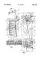
- FIG. 2is an enlarged cross section elevation of a basket and portions of first and second adjacent baskets on the upstream side of the traveling water screen shown in FIG. 1.
- FIG. 3is a partial sectional view taken generally along line 3--3 in FIG. 2, showing forward and rear struts and the water screen supported on the lower lip beam.
- FIG. 1Illustrated in FIG. 1 is a traveling water screen 10 for screening debris from water flowing in a downstream direction through a water inlet channel.
- the downstream directionis also referred to herein as “rearward”
- the opposite or upstream directionis also referred to as "forward”.
- the traveling water screen 10is similar to the traveling water screen disclosed in U.S. Pat. No. 4,582,601, which is assigned to the assignee hereof and is incorporated herein by reference.
- the traveling water screen 10includes an upright or vertical frame 12.
- the frame 12has a downstream side 14 facing in the downstream direction and an opposed upstream side 16 facing in the upstream direction.
- the frame 12includes a pair of spaced, parallel vertical support members 18 and 20.
- the frame 12also has a boot portion 22 adjacent the bottom of the channel and a head portion 24 above the level of the water (not shown) in the channel.
- the traveling water screen 10also includes a horizontally extending shelf 26 at the head portion 24 of the frame 12.
- the shelf 26includes a fish return trough 28 extending away from the traveling water screen 10 for returning fish to a body of water, such as a river or lake, away from the water inlet channel.
- the traveling water screen 10also includes a head shaft (not shown) supported at the head portion 24 of the frame 12 for rotation about a horizontal axis. A pair of head sprockets (not shown) are mounted in spaced relation on the head shaft.
- the traveling water screen 10also includes a foot shaft (not shown) supported at the boot portion 22 of the frame 12 for rotation about a horizontal axis. A pair of foot sprockets (not shown) are mounted in spaced relation on the foot shaft. A pair of continuous chains (not shown) are trained around the head and foot sprockets.
- the traveling water screen 10also includes a plurality of baskets 30 mounted on the chains and arranged in close edge-to-edge relation in a continuous train around the head and foot sprockets.
- the baskets 30are supported by the chains for movement about a circuitous path defined around the head and foot shafts.
- the traveling water screen 10also includes means for moving the train of baskets 30 about the path around the head and foot shafts.
- the means for moving the train of baskets 30includes a drive motor 32 operably connected to a gear reducer 34, the gear reducer 34 having a drive sprocket (not shown) mounted thereon.
- the drive sprocketis operably connected by a drive chain (not shown) to a driven sprocket (not shown) mounted on the head shaft.
- the drive motor 32thus connected rotates the head shaft and thereby moves the chains and the train of baskets 30 about the circuitous path defined around the head and foot shafts.
- the baskets 30move downwardly from the head shaft toward the foot shaft on the downstream side 14 of the frame 12. As seen in FIGS. 1 and 2, the baskets 30 move upwardly from the foot shaft toward the head shaft and thereby form a substantially continuous upwardly moving screen on the upstream side 16 of the frame 12.
- each basket 30is mounted on the chains in close edge-to-edge relationship to upper and lower adjacent baskets 130 and 230.
- Each basket 30includes a water screen mesh or water screen 36 mounted in a generally rectangular frame 38.
- the water screen 36is rectangularly shaped and includes opposed upper and lower edge portions 40 and 42 and opposed end edge portions 44 (one shown in FIG. 1).
- the upper and lower edge portions 40 and 42include respective elongated flanges 48 and 50.
- the end edge portions 44also include respective flanges (not shown).
- the flangesare clamped against the frame 38 by spaced clamps 56 (one partially shown in FIG. 3).
- Each clamp 56is fixed to the frame 38 by a bolt 58.
- the upper and lower edge portions 40 and 42 and end edge portions 44are supported by the frame 38.
- the water screen 36is inclined forwardly from the lower lip beam 108 to the upper lip beam 80.
- the frame 38can be constructed of other suitable materials, in the illustrated embodiment the frame 38 is constructed of composite fiberglass material.
- the frame 38includes opposed end members or plates 60 and 62.
- the end plates 60 and 62are mirror images of each other, and only the end plate 60 will be described in detail.
- the end plate 60includes a straight rear edge portion (not shown), an arcuate front edge portion 66 spaced from the rear edge portion, an arcuate upper end portion 68 connecting the rear and front edge portions, and an arcuate lower end portion (not shown) opposite the upper end portion 68.
- the end plate 60also includes opposed inner and outer surfaces 70 and 72. Four plugs or projections 74 extend inwardly from the inner surface 70.
- the end plate 60also includes four spaced apertures 76 for receiving bolts 78 connecting the end plate 60 to a respective one of the chains.
- the end plate 60also includes apertures extending between the inner and outer surfaces 70 and 74 for receiving bolts for securing clamps 56 to the end plate 60 to clamp the end edge portion flange against the end plate 60.
- the end edge portions 44are supported by the end plates 60 and 62.
- the frame 38includes an elongated upper lip beam 80 (see FIG. 2) extending between the end plates 60 and 62.
- the upper lip beam 80includes an outer surface 82 and an inner surface 84 opposite from the outer surface 82.
- Two hollow cores 86are defined between the outer and inner surfaces 82 and 84.
- An end plate projection 74is received in each end of each hollow core 86.
- the projections 74 received in the hollow cores 86join the end plates 60 and 62 to the upper lip beam 80.
- the outer surface 82includes an elongated forward surface 88.
- the forward surface 88faces in the upstream direction and includes upper and lower forward edge portions 90 and 92.
- the forward surface 88aligns or mates with the upstream wall of the lower lip beam 108 of the upper adjacent basket 130 to define a generally uniform, convex water deflection surface.
- the inner surface 84extends rearwardly from the lower forward edge portion 92.
- the outer surface 82includes an upper portion 96 extending rearwardly from the upper forward edge portion 90.
- the upper portion 96includes an elongated slot 98.
- a plurality of longitudinally spaced aperturesare drilled between the outer and inner surfaces 82 and 84 in the slot 98, for receiving bolts 58.
- Bolts 58retain the clamps 56 (not shown) against the water screen flange 48 to clamp the water screen upper edge portion 40 against the inner surface 84 of the upper lip beam 80.
- the upper lip beam 80supports the upper edge portion 40 of the water screen 36.
- Bolts 58extend through apertures in front struts 100 to connect the front struts 100 to the upper lip beam 80.
- the inner surface 84 and the upper portion 96 of the outer surface 82are joined at a rear edge portion 102.
- a plurality of longitudinally spaced apertures(not shown) are drilled between the outer surface 82 and the inner surface 84 in the rear edge portion 102, for receiving bolts 58.
- Bolts 58extend through apertures in rear struts 104 to connect the rear struts 104 to the upper lip beam 80.
- the basket 30includes a pair of spaced apart front struts 100 (one shown).
- the front struts 100extend vertically and rearwardly from the inner surface 84 of the upper lip beam 80 to the rear edge portion of a lower lip beam 108 (described below).
- Each front strut 100is an elongated, generally I-shaped member having a longitudinal axis.
- Each front strut 100includes upper and lower flanges 110 (see FIG. 2) and 112 (see FIG. 3) perpendicular to the longitudinal axis. The upper and lower flanges 110 and 112 respectively abut the upper and lower lip beams 80 and 108.
- Each flange 110 and 112has therein a pair of apertures (not shown) for receiving bolts 58 and thus connecting the front strut 100 to the upper and lower lip beams 80 and 108.
- the front struts 100support the upper and lower lip beams 80 and 108 intermediate the end plates 60 and 62 and thus prevent the frame 38 from excessively twisting or bending.
- Each front strut 100also includes an elongated front edge portion 114 and a rear edge portion 116 opposite the front edge portion 114. The front edge portion 114 abuts the water screen 36 between the upper and lower lip beams 80 and 108 and thus prevents excessive deflection of the water screen 36 in the downstream direction.
- the basket 30also includes a pair of rear struts 104 (one shown) spaced between the end plates 60 and 62.
- the rear struts 104extend vertically between the rear edge portion 102 of the upper lip beam 80 and the rear edge portion 106 of the lower lip beam 108.
- Each rear strut 104is an elongated, generally T-shaped member having a longitudinal axis.
- Each rear strut 104includes upper and lower flanges 120 and 122 perpendicular to the longitudinal axis. The upper and lower flanges 120 and 122 respectively abut the upper and lower lip beams 80 and 108.
- Each flange 120 and 122has therein a pair of apertures (not shown) for receiving bolts 58 and thus connecting the rear strut 104 to the respective upper or lower lip beam 80 or 108.
- the rear struts 104support the upper and lower lip beams 80 and 108 intermediate the end plates 60 and 62 and thus prevent the frame 38 from excessively twisting or bending.
- the elongated lower lip beam 108extends between the end plates 60 and 62 and includes an outer surface 124 and an inner surface 126 opposite from the outer surface 124.
- Two hollow cores 86are defined between the outer and inner surfaces 124 and 126.
- An end plate projection 74is received in each end of each hollow core 86.
- the projections 74 received in the hollow cores 86join the end plates 60 and 62 to the lower lip beam 108.
- the outer surface 124 and the inner surface 126are joined at an elongated rear edge portion 106.
- a plurality of longitudinally spaced aperturesare drilled between the outer surface 124 and the inner surface 126 in the rear edge portion 106, for receiving bolts 58. As best shown in FIG.
- various of the bolts 58retain clamps 56 against the water screen flange 50 to clamp the water screen lower edge portion 42 against the rear edge portion 106.
- the lower lip beam 108supports the lower edge portion 42 of the water screen 36.
- Various of the bolts 58extend through the apertures and aligned apertures in the front and rear struts 100 and 104 to connect the struts to the lower lip beam 108.
- the inner surface 126 of the lower lip beam 108is arcuately shaped and defines an elongated, upwardly opening channel 128 generally upstream of the lower edge portion 42 of the water screen 36.
- the inner surface 126includes a rear portion 130 extending forwardly and downwardly from the rear edge portion 106, such that a channel rear edge 132 is defined at the intersection of the rear portion 130 and the rear edge portion 106.
- the inner surface 126also includes a front portion 134 extending forwardly and upwardly from the rear portion 130 and terminating at an elongated front upper edge portion 136.
- the front upper edge portion 136is spaced upstream or forward of the lower edge portion 42 of the water screen 36, such that an elongated channel opening is defined between the front upper edge portion 136 and the water screen 36.
- the front upper edge portion 136is also spaced above the level of the channel rear edge 132 and the lower edge portion 42 of the water screen 36.
- the channel 128has an upper region adjacent the channel opening and a lower region 140 below the upper region.
- the basket 30also includes means for generating substantially quiescent conditions in the bottom region 140 of the water in the channel 128.
- this meansincludes an upstream wall 142 on the lower lip beam 108.
- the upstream wall 142is defined by the outer surface 124 and extends generally downwardly and forwardly from the front upper edge portion 136.
- the upstream wall 142includes a lower portion 144 and an upper portion 146.
- the upper portion 146includes a concave upper forward surface 148 facing in the upstream direction and terminating at the front upper edge portion 136.
- the upper forward surface 148is inclined upwardly and rearwardly with respect to the direction of flow of water through the water screen 36, i.e., upwardly in the downstream direction.
- the upper portion 146 of the upstream wall 142has a spoiler shape and is inclined upwardly and rearwardly for deflecting water upwardly and over the upwardly opening channel 128.
- the lower portion 144 of the upstream wall 142includes a convex generally vertical lower forward surface 149 facing in the upstream direction and joining the upper forward surface 148.
- the lower forward surface 149is aligned or mates with the forward surface 88 of the upper lip beam 80 of the lower adjacent basket 30 to define a generally uniform, convex water deflection surface 94. Water is deflected by the water deflection surface 94 upwardly toward the upper forward surface 148 and downwardly toward the water screen 36 of the lower adjacent basket 230.
- substantially quiescent conditionsare generated in the bottom region 140 of the water in the channel 128.
- the outer surface 124also includes a concave lower surface portion 152 below the lower forward surface 149 of the upstream wall 142.
- the lower surface portion 152is spaced slightly from and is adapted to house or nest with the outer surface 82 of the upper lip beam 80 of the lower adjacent basket 230.
- a narrow gap or space 254is defined between the lower surface portion 152 and the outer surface 82 of the upper lip beam 80 of the lower adjacent basket 230.
- Another space 154is defined between the outer surface 82 of the upper lip beam 80 of the basket 30 and the lower surface portion 152 of the upper adjacent basket 130. The spaces 154 and 254 provide clearance between the baskets 30, 103 and 230 for the baskets to pass around the head and foot shafts.
- upper and lower lip beamscould be constructed of other materials, in one preferred embodiment of the invention they are formed from pultruded fiberglass and are manufactured by Bedford Reinforced Plastics (Bedford, Pa.).
- the basket 30also includes means 156 for sealing between the basket 30 and adjacent baskets 130 and 230 to prevent unscreened water from flowing through the traveling water screen 10 between the baskets 30, 130 and 230.
- the sealing means 156is an elongated resilient blade.
- the resilient blade 156can be constructed of any suitable resilient material, such as 80 shore A durometer neoprene or ethylene propylene.
- the resilient blade 156includes an inner edge portion and an outer edge portion opposite from the inner edge portion.
- the inner edge portion of the blade 156is mounted in an elongated F-shaped bracket 162.
- the bracket 162is mounted in the slot 98 in the outer surface 82 of the upper lip beam 80 by bolts 58.
- the resilient blade 156is mounted on the upper lip beam 80 of the basket 30.
- the outer edge portion of the blade 156resiliently engages the lower lip beam 108 of the upper adjacent basket 130 to prevent water from flowing through the space 154 between the upper lip beam 80 of the basket 30 and the lower lip beam 108 of the upper adjacent basket 130.
- a resilient blade 156is mounted on the upper lip beam 80 of each of the baskets 30 and each resiliently engages the lower lip beam 108 of a respective adjacent basket to prevent water from flowing between the baskets.
- the resilient blade 156can be supported by one of the upper or lower lip beams 80 or 108 of each basket 30 to resiliently engage the other of the upper or lower lip beam 80 or 108 of a respective adjacent basket and thus prevent unscreened water from flowing through the traveling water screen 10 between the baskets.
- the train of baskets 30moves upwardly on the upstream side 16 of the frame 12. Water flows in the downstream direction through the water screens 36 of the upwardly moving baskets 30, such that debris and fish are screened out of the water by the water screens 36.
- the upper and lower lip beams 80 and 108 of the baskets 30are spaced slightly from the respective upper and lower lip beams 80 and 108 of the upper and lower adjacent baskets 130 and 230 to provide clearance for the baskets 30 to pass around the head and foot shafts.
- the resilient blade 156 mounted on the upper lip beam 80 of each basket 30resiliently engages the lower lip beam 108 of a respective upper adjacent basket 30 to prevent water from flowing through the traveling water screen 10 between the baskets 30.
- the upstream wall 142 of the lower lip beam 108generates substantially quiescent conditions in the bottom region 140 of the water in the channel 128, so that the fish in the channel 128 are not excessively tossed about and thus injured or killed.
- the upper portion 146 of the upstream wall 142has a spoiler shape and is inclined upwardly and rearwardly, and thus deflects water upwardly and over the upwardly opening channel 128.
- the lower portion 144 of the upstream wall 142includes a convex lower forward surface 149 which mates with the forward surface 88 of the upper lip beam 80 of the lower adjacent basket 30 to define a convex water deflection surface 94.
- Wateris deflected by the water deflection surface 94 upwardly toward the upper forward surface 148 and downwardly toward the water screen 36 of the lower adjacent basket 30.
- water flowing in the downstream directionis deflected away from the channel 128, and substantially quiescent conditions exist in the lower region 140 of the water in the channel 128.
- the fishslide out of the channel 128, across the water screen 36, across the upper lip beam 80, and are dumped out of the upturned basket 30 and into the fish return trough 28 in uninjured condition. The fish are thus returned to the body of water through the fish return trough 28 in live and uninjured condition.
Landscapes
- Engineering & Computer Science (AREA)
- General Engineering & Computer Science (AREA)
- Mechanical Engineering (AREA)
- Civil Engineering (AREA)
- Structural Engineering (AREA)
- Chemical & Material Sciences (AREA)
- Chemical Kinetics & Catalysis (AREA)
- Filtration Of Liquid (AREA)
Abstract
Description
Claims (35)
Priority Applications (1)
| Application Number | Priority Date | Filing Date | Title |
|---|---|---|---|
| US08/221,368US5501793A (en) | 1994-03-31 | 1994-03-31 | Traveling water screen including improved basket |
Applications Claiming Priority (1)
| Application Number | Priority Date | Filing Date | Title |
|---|---|---|---|
| US08/221,368US5501793A (en) | 1994-03-31 | 1994-03-31 | Traveling water screen including improved basket |
Publications (1)
| Publication Number | Publication Date |
|---|---|
| US5501793Atrue US5501793A (en) | 1996-03-26 |
Family
ID=22827526
Family Applications (1)
| Application Number | Title | Priority Date | Filing Date |
|---|---|---|---|
| US08/221,368Expired - LifetimeUS5501793A (en) | 1994-03-31 | 1994-03-31 | Traveling water screen including improved basket |
Country Status (1)
| Country | Link |
|---|---|
| US (1) | US5501793A (en) |
Cited By (16)
| Publication number | Priority date | Publication date | Assignee | Title |
|---|---|---|---|---|
| US6187184B1 (en) | 1999-07-30 | 2001-02-13 | Niagara Mohawk Power Corporation | Traveling water screen having improved basket |
| US20050016908A1 (en)* | 2003-06-02 | 2005-01-27 | Hans Huber Ag Maschinen-Und Anlagenbau | Apparatus for the separation and removal of liquid borne solid waste |
| US20060032798A1 (en)* | 2004-08-16 | 2006-02-16 | Laitram, L.L.C. | Water screen |
| US20060037897A1 (en)* | 2004-08-20 | 2006-02-23 | Philip Jackson | Water intake rotary screen |
| US20060185967A1 (en)* | 2005-02-24 | 2006-08-24 | Sedlacek Kyle J | Screen belt and modules |
| US20070017858A1 (en)* | 2005-07-22 | 2007-01-25 | Laitram, L.L.C. | Horizontally traveling water screen |
| US20070215532A1 (en)* | 2006-03-14 | 2007-09-20 | Wunsch Philip J | Water screen system with boot seal |
| US20070241039A1 (en)* | 2006-04-13 | 2007-10-18 | Wilcher Stephen B | Perforated plate element screen with sealed element design |
| US20080083665A1 (en)* | 2006-10-09 | 2008-04-10 | Wunsch Philip J | Water screen system with compressible boot seal |
| WO2010015317A1 (en)* | 2008-08-08 | 2010-02-11 | Passavant-Geiger Gmbh | Travelling band screen machine |
| WO2010087541A1 (en)* | 2009-01-30 | 2010-08-05 | Kc Samyang Water Systems Co., Ltd. | Combination traveling water screen apparatus |
| US20120175294A1 (en)* | 2011-01-11 | 2012-07-12 | Essa Co., Ltd. | Apparatus for filtering sewage and wastewater |
| GB2504198A (en)* | 2012-05-24 | 2014-01-22 | Beaudrey & Cie | System and method for filtering a flow of water |
| US20140299528A1 (en)* | 2013-04-03 | 2014-10-09 | Laitram, L.L.C. | Aquatic life and debris collection device for a water screen |
| USD828486S1 (en) | 2015-08-06 | 2018-09-11 | Evoqua Water Technologies Llc | Fine mesh traveling water screen assembly |
| US20220023779A1 (en)* | 2020-07-23 | 2022-01-27 | Parkson Corporation | Bar screen filter apparatus and method |
Citations (22)
| Publication number | Priority date | Publication date | Assignee | Title |
|---|---|---|---|---|
| GB319068A (en)* | 1928-06-19 | 1929-09-19 | Robert Arnold Blakeborough | Improvements in apparatus for straining liquids |
| US1781223A (en)* | 1928-11-12 | 1930-11-11 | Chain Belt Co | Endless sectional water screen |
| US1910860A (en)* | 1930-10-31 | 1933-05-23 | Link Belt Co | Tray for water screens |
| DE612987C (en)* | 1934-02-21 | 1935-05-09 | Fried Krupp Grusonwerk Akt Ges | Sieve covering for fine screening using vibrating sieves |
| US2428757A (en)* | 1944-06-29 | 1947-10-07 | Chain Belt Co | Attachment means for conveyer flights |
| US2765923A (en)* | 1953-04-03 | 1956-10-09 | Milan V Novak | Blood filter |
| US3684091A (en)* | 1969-12-11 | 1972-08-15 | Lehmann Hein & Co Ag | Tensionable elastic screen bottom |
| US3850804A (en)* | 1972-12-22 | 1974-11-26 | Rex Chainbelt Inc | Screens for water intake systems |
| US3868324A (en)* | 1972-12-22 | 1975-02-25 | Envirex | Water intake and fish return system |
| US3900628A (en)* | 1973-06-13 | 1975-08-19 | Linatex Corp Of America | Pretensioned screen panel |
| US4199456A (en)* | 1977-06-24 | 1980-04-22 | Royce Equipment Company | Apparatus for a screen assembly for removing solids from fluids |
| US4302331A (en)* | 1980-05-30 | 1981-11-24 | Condit Jr Paul A | Filter bucket for a flight conveyor |
| SU923570A1 (en)* | 1980-07-04 | 1982-04-30 | Всесоюзный Научно-Исследовательский И Проектно-Конструкторский Институт Нефтяного Машиностроения | Device for cleaning drilling mud |
| US4360426A (en)* | 1981-03-02 | 1982-11-23 | Fmc Corporation | Joint between traveling water screen trays |
| US4443126A (en)* | 1979-11-19 | 1984-04-17 | Envirex Inc. | Water screening clamp strip |
| US4541930A (en)* | 1983-04-06 | 1985-09-17 | Fmc Corporation | Interchangeable screen panels for a traveling water screen |
| US4582601A (en)* | 1984-03-29 | 1986-04-15 | Envirex Inc. | Polymeric basket frame for a traveling water screen |
| US4634535A (en)* | 1985-03-25 | 1987-01-06 | Lott W Gerald | Drilling mud cleaning method and apparatus |
| US4935131A (en)* | 1988-12-06 | 1990-06-19 | Greenbank Engineering Group, Ltd. | Dual-flow band screen conversion apparatus |
| US5015383A (en)* | 1989-06-15 | 1991-05-14 | Johnson Filtration Systems Inc. | Slotted screen scallops for high loading pressures and method of making same |
| US5242583A (en)* | 1992-08-03 | 1993-09-07 | Envirex Inc. | Wire screen clamp |
| US5326460A (en)* | 1993-02-10 | 1994-07-05 | Envirex Inc. | Pretensioned mesh insert and method for producing a pretensioned mesh insert |
- 1994
- 1994-03-31USUS08/221,368patent/US5501793A/ennot_activeExpired - Lifetime
Patent Citations (22)
| Publication number | Priority date | Publication date | Assignee | Title |
|---|---|---|---|---|
| GB319068A (en)* | 1928-06-19 | 1929-09-19 | Robert Arnold Blakeborough | Improvements in apparatus for straining liquids |
| US1781223A (en)* | 1928-11-12 | 1930-11-11 | Chain Belt Co | Endless sectional water screen |
| US1910860A (en)* | 1930-10-31 | 1933-05-23 | Link Belt Co | Tray for water screens |
| DE612987C (en)* | 1934-02-21 | 1935-05-09 | Fried Krupp Grusonwerk Akt Ges | Sieve covering for fine screening using vibrating sieves |
| US2428757A (en)* | 1944-06-29 | 1947-10-07 | Chain Belt Co | Attachment means for conveyer flights |
| US2765923A (en)* | 1953-04-03 | 1956-10-09 | Milan V Novak | Blood filter |
| US3684091A (en)* | 1969-12-11 | 1972-08-15 | Lehmann Hein & Co Ag | Tensionable elastic screen bottom |
| US3850804A (en)* | 1972-12-22 | 1974-11-26 | Rex Chainbelt Inc | Screens for water intake systems |
| US3868324A (en)* | 1972-12-22 | 1975-02-25 | Envirex | Water intake and fish return system |
| US3900628A (en)* | 1973-06-13 | 1975-08-19 | Linatex Corp Of America | Pretensioned screen panel |
| US4199456A (en)* | 1977-06-24 | 1980-04-22 | Royce Equipment Company | Apparatus for a screen assembly for removing solids from fluids |
| US4443126A (en)* | 1979-11-19 | 1984-04-17 | Envirex Inc. | Water screening clamp strip |
| US4302331A (en)* | 1980-05-30 | 1981-11-24 | Condit Jr Paul A | Filter bucket for a flight conveyor |
| SU923570A1 (en)* | 1980-07-04 | 1982-04-30 | Всесоюзный Научно-Исследовательский И Проектно-Конструкторский Институт Нефтяного Машиностроения | Device for cleaning drilling mud |
| US4360426A (en)* | 1981-03-02 | 1982-11-23 | Fmc Corporation | Joint between traveling water screen trays |
| US4541930A (en)* | 1983-04-06 | 1985-09-17 | Fmc Corporation | Interchangeable screen panels for a traveling water screen |
| US4582601A (en)* | 1984-03-29 | 1986-04-15 | Envirex Inc. | Polymeric basket frame for a traveling water screen |
| US4634535A (en)* | 1985-03-25 | 1987-01-06 | Lott W Gerald | Drilling mud cleaning method and apparatus |
| US4935131A (en)* | 1988-12-06 | 1990-06-19 | Greenbank Engineering Group, Ltd. | Dual-flow band screen conversion apparatus |
| US5015383A (en)* | 1989-06-15 | 1991-05-14 | Johnson Filtration Systems Inc. | Slotted screen scallops for high loading pressures and method of making same |
| US5242583A (en)* | 1992-08-03 | 1993-09-07 | Envirex Inc. | Wire screen clamp |
| US5326460A (en)* | 1993-02-10 | 1994-07-05 | Envirex Inc. | Pretensioned mesh insert and method for producing a pretensioned mesh insert |
Non-Patent Citations (2)
| Title |
|---|
| The Failure and Rehabilitation of a Fish Conserving Device ; Transactions of the American Fisheries Society 121:678 679 (1992).* |
| The Failure and Rehabilitation of a Fish-Conserving Device ; Transactions of the American Fisheries Society 121:678-679 (1992). |
Cited By (33)
| Publication number | Priority date | Publication date | Assignee | Title |
|---|---|---|---|---|
| US6187184B1 (en) | 1999-07-30 | 2001-02-13 | Niagara Mohawk Power Corporation | Traveling water screen having improved basket |
| US20050016908A1 (en)* | 2003-06-02 | 2005-01-27 | Hans Huber Ag Maschinen-Und Anlagenbau | Apparatus for the separation and removal of liquid borne solid waste |
| US7300572B2 (en)* | 2004-08-16 | 2007-11-27 | Laitram, L.L.C. | Water screen |
| US20060032798A1 (en)* | 2004-08-16 | 2006-02-16 | Laitram, L.L.C. | Water screen |
| US7048850B2 (en) | 2004-08-16 | 2006-05-23 | Laitram, L.L.C. | Water screen |
| US20060201859A1 (en)* | 2004-08-16 | 2006-09-14 | Laitram, L.L.C. | Water screen |
| US20060037897A1 (en)* | 2004-08-20 | 2006-02-23 | Philip Jackson | Water intake rotary screen |
| FR2874334A1 (en)* | 2004-08-20 | 2006-02-24 | Beaudrey Et Cie Societe Anonyme | ROTARY SIEVE FOR WATER TAKING |
| US7326336B2 (en) | 2004-08-20 | 2008-02-05 | E. Beaudrey Et Cie | Water intake rotary screen |
| US20060185967A1 (en)* | 2005-02-24 | 2006-08-24 | Sedlacek Kyle J | Screen belt and modules |
| US7575113B2 (en) | 2005-02-24 | 2009-08-18 | Laitram, L.L.C. | Screen belt and modules |
| US20070017858A1 (en)* | 2005-07-22 | 2007-01-25 | Laitram, L.L.C. | Horizontally traveling water screen |
| US7722762B2 (en) | 2005-07-22 | 2010-05-25 | Laitram, L.L.C. | Horizontally traveling water screen |
| US20070215532A1 (en)* | 2006-03-14 | 2007-09-20 | Wunsch Philip J | Water screen system with boot seal |
| US7776212B2 (en) | 2006-03-14 | 2010-08-17 | Laitram, L.L.C. | Water screen system with boot seal |
| US20070241039A1 (en)* | 2006-04-13 | 2007-10-18 | Wilcher Stephen B | Perforated plate element screen with sealed element design |
| US7510650B2 (en)* | 2006-04-13 | 2009-03-31 | Wsg & Solutions, Inc. | Perforated plate element screen with sealed element design |
| US20080083665A1 (en)* | 2006-10-09 | 2008-04-10 | Wunsch Philip J | Water screen system with compressible boot seal |
| US7393451B2 (en) | 2006-10-09 | 2008-07-01 | Laitram, L.L.C. | Water screen system with compressible boot seal |
| WO2010015317A1 (en)* | 2008-08-08 | 2010-02-11 | Passavant-Geiger Gmbh | Travelling band screen machine |
| US8092674B2 (en)* | 2008-08-08 | 2012-01-10 | Passavant-Geiger Gmbh | Traveling band screen machine |
| US20110139692A1 (en)* | 2008-08-08 | 2011-06-16 | Klaus Heil | Travelling band screen machine |
| US20110186502A1 (en)* | 2009-01-30 | 2011-08-04 | Kc Samyang Water Systems Co., Ltd. | Combination traveling water screen apparatus |
| WO2010087541A1 (en)* | 2009-01-30 | 2010-08-05 | Kc Samyang Water Systems Co., Ltd. | Combination traveling water screen apparatus |
| US20120175294A1 (en)* | 2011-01-11 | 2012-07-12 | Essa Co., Ltd. | Apparatus for filtering sewage and wastewater |
| US8753506B2 (en)* | 2011-01-11 | 2014-06-17 | Essa Co., Ltd. | Apparatus for filtering sewage and wastewater |
| GB2504198A (en)* | 2012-05-24 | 2014-01-22 | Beaudrey & Cie | System and method for filtering a flow of water |
| GB2504198B (en)* | 2012-05-24 | 2014-09-24 | Beaudrey & Cie | System and method for filtering a flow of water |
| US20140299528A1 (en)* | 2013-04-03 | 2014-10-09 | Laitram, L.L.C. | Aquatic life and debris collection device for a water screen |
| US9567719B2 (en)* | 2013-04-03 | 2017-02-14 | Laitram, L.L.C. | Aquatic life and debris collection device for a water screen |
| USD828486S1 (en) | 2015-08-06 | 2018-09-11 | Evoqua Water Technologies Llc | Fine mesh traveling water screen assembly |
| US20220023779A1 (en)* | 2020-07-23 | 2022-01-27 | Parkson Corporation | Bar screen filter apparatus and method |
| US11633680B2 (en)* | 2020-07-23 | 2023-04-25 | Parkson Corporation | Bar screen filter apparatus and method |
Similar Documents
| Publication | Publication Date | Title |
|---|---|---|
| US5501793A (en) | Traveling water screen including improved basket | |
| US4360426A (en) | Joint between traveling water screen trays | |
| US5415766A (en) | Traveling water screen including boot seal | |
| US5326460A (en) | Pretensioned mesh insert and method for producing a pretensioned mesh insert | |
| US6187184B1 (en) | Traveling water screen having improved basket | |
| US3850804A (en) | Screens for water intake systems | |
| US5242583A (en) | Wire screen clamp | |
| US3868324A (en) | Water intake and fish return system | |
| JP5403615B2 (en) | Water screen system with pressable hem seal | |
| US4321996A (en) | Cleated belt forage conveyor | |
| US7364652B2 (en) | Screening apparatus | |
| CN101400423B (en) | Water screen system with boot seal | |
| KR101162330B1 (en) | Rake on the bar screen with rotating rakes | |
| CA1328231C (en) | Curved diverter plate assembly for interchangeability of various models of traveling water screens | |
| US10669683B2 (en) | Fine mesh fish larvae protection system for traveling water screens | |
| US5419832A (en) | Guide lock for a traveling water screen | |
| KR100941028B1 (en) | Screen basket of rotating screen device | |
| JPH0378448B2 (en) | ||
| US6267880B1 (en) | Mechanical screen, in particular filter apron of a chain filter | |
| GB2407782A (en) | A band screen assembly | |
| JPS58168707A (en) | Joint between moving water filter plates | |
| KR102384955B1 (en) | Rotary type screener machine | |
| KR100719521B1 (en) | Moving screen device for separating floats in water treatment plant | |
| KR100628834B1 (en) | Screen plate for Moving screen apparatus | |
| CA2342469A1 (en) | Filter panels for filter screen units |
Legal Events
| Date | Code | Title | Description |
|---|---|---|---|
| AS | Assignment | Owner name:ENVIREX INC., WISCONSIN Free format text:ASSIGNMENT OF ASSIGNORS INTEREST;ASSIGNORS:CHEESMAN, ROBERT R.;EHLEITER, JAMES A.;GASS, DON N.;AND OTHERS;REEL/FRAME:007009/0445;SIGNING DATES FROM 19940519 TO 19940524 | |
| AS | Assignment | Owner name:ENVIREX, INC., WISCONSIN Free format text:ASSIGNMENT OF ASSIGNORS INTEREST;ASSIGNOR:FLETCHER, R. IAN;REEL/FRAME:007041/0038 Effective date:19940614 | |
| STCF | Information on status: patent grant | Free format text:PATENTED CASE | |
| FEPP | Fee payment procedure | Free format text:PAYOR NUMBER ASSIGNED (ORIGINAL EVENT CODE: ASPN); ENTITY STATUS OF PATENT OWNER: LARGE ENTITY | |
| FPAY | Fee payment | Year of fee payment:4 | |
| FEPP | Fee payment procedure | Free format text:PAYER NUMBER DE-ASSIGNED (ORIGINAL EVENT CODE: RMPN); ENTITY STATUS OF PATENT OWNER: LARGE ENTITY Free format text:PAYOR NUMBER ASSIGNED (ORIGINAL EVENT CODE: ASPN); ENTITY STATUS OF PATENT OWNER: LARGE ENTITY | |
| FEPP | Fee payment procedure | Free format text:PAYER NUMBER DE-ASSIGNED (ORIGINAL EVENT CODE: RMPN); ENTITY STATUS OF PATENT OWNER: LARGE ENTITY Free format text:PAYOR NUMBER ASSIGNED (ORIGINAL EVENT CODE: ASPN); ENTITY STATUS OF PATENT OWNER: LARGE ENTITY | |
| FPAY | Fee payment | Year of fee payment:8 | |
| AS | Assignment | Owner name:SIEMENS WATER TECHNOLOGIES CORP., MASSACHUSETTS Free format text:MERGER;ASSIGNOR:ENVIREX INC.;REEL/FRAME:018442/0420 Effective date:20060804 | |
| FPAY | Fee payment | Year of fee payment:12 | |
| AS | Assignment | Owner name:SIEMENS WATER TECHNOLOGIES HOLDING CORP., PENNSYLV Free format text:MERGER;ASSIGNOR:SIEMENS WATER TECHNOLOGIES CORP.;REEL/FRAME:026106/0467 Effective date:20110401 | |
| AS | Assignment | Owner name:SIEMENS INDUSTRY, INC., GEORGIA Free format text:MERGER;ASSIGNOR:SIEMENS WATER TECHNOLOGIES HOLDING CORP.;REEL/FRAME:026138/0593 Effective date:20110401 |