US5501545A - Retroreflective structure and road marker employing same - Google Patents
Retroreflective structure and road marker employing sameDownload PDFInfo
- Publication number
- US5501545A US5501545AUS08/336,467US33646794AUS5501545AUS 5501545 AUS5501545 AUS 5501545AUS 33646794 AUS33646794 AUS 33646794AUS 5501545 AUS5501545 AUS 5501545A
- Authority
- US
- United States
- Prior art keywords
- retroreflective
- retroreflective structure
- road marker
- angle
- base
- Prior art date
- Legal status (The legal status is an assumption and is not a legal conclusion. Google has not performed a legal analysis and makes no representation as to the accuracy of the status listed.)
- Expired - Lifetime
Links
- 239000003550markerSubstances0.000titleclaimsdescription42
- 239000000463materialSubstances0.000claimsdescription9
- 230000003287optical effectEffects0.000claimsdescription9
- 229910052751metalInorganic materials0.000claimsdescription6
- 239000002184metalSubstances0.000claimsdescription6
- 239000004593EpoxySubstances0.000claimsdescription3
- 239000000203mixtureSubstances0.000claimsdescription3
- 229920000515polycarbonatePolymers0.000claimsdescription3
- 239000004417polycarbonateSubstances0.000claimsdescription3
- 229920000728polyesterPolymers0.000claimsdescription3
- 239000005062PolybutadieneSubstances0.000claimsdescription2
- 229920002367PolyisobutenePolymers0.000claimsdescription2
- 229920001328Polyvinylidene chloridePolymers0.000claimsdescription2
- BQCADISMDOOEFD-UHFFFAOYSA-NSilverChemical compound[Ag]BQCADISMDOOEFD-UHFFFAOYSA-N0.000claimsdescription2
- 229910052782aluminiumInorganic materials0.000claimsdescription2
- XAGFODPZIPBFFR-UHFFFAOYSA-NaluminiumChemical compound[Al]XAGFODPZIPBFFR-UHFFFAOYSA-N0.000claimsdescription2
- PCHJSUWPFVWCPO-UHFFFAOYSA-NgoldChemical compound[Au]PCHJSUWPFVWCPO-UHFFFAOYSA-N0.000claimsdescription2
- 229910052737goldInorganic materials0.000claimsdescription2
- 239000010931goldSubstances0.000claimsdescription2
- 229920002857polybutadienePolymers0.000claimsdescription2
- 229920002635polyurethanePolymers0.000claimsdescription2
- 239000004814polyurethaneSubstances0.000claimsdescription2
- 239000004800polyvinyl chlorideSubstances0.000claimsdescription2
- 229920000915polyvinyl chloridePolymers0.000claimsdescription2
- 239000005033polyvinylidene chlorideSubstances0.000claimsdescription2
- 229910052709silverInorganic materials0.000claimsdescription2
- 239000004332silverSubstances0.000claimsdescription2
- 239000003989dielectric materialSubstances0.000claims1
- 150000002739metalsChemical class0.000claims1
- 229920000058polyacrylatePolymers0.000claims1
- 229920005554polynitrilePolymers0.000claims1
- 238000000034methodMethods0.000abstractdescription6
- 229920000642polymerPolymers0.000description15
- 239000000853adhesiveSubstances0.000description7
- 230000001070adhesive effectEffects0.000description7
- 238000003491arrayMethods0.000description7
- -1poly(ethylene-propylene)Polymers0.000description6
- 238000000576coating methodMethods0.000description5
- 238000001125extrusionMethods0.000description5
- 239000011248coating agentSubstances0.000description4
- 210000000887faceAnatomy0.000description4
- 239000004033plasticSubstances0.000description3
- 229920003023plasticPolymers0.000description3
- 230000006378damageEffects0.000description2
- 230000001419dependent effectEffects0.000description2
- 238000005323electroformingMethods0.000description2
- 230000003116impacting effectEffects0.000description2
- 238000004519manufacturing processMethods0.000description2
- JOYRKODLDBILNP-UHFFFAOYSA-NEthyl urethaneChemical compoundCCOC(N)=OJOYRKODLDBILNP-UHFFFAOYSA-N0.000description1
- 238000005299abrasionMethods0.000description1
- 150000001252acrylic acid derivativesChemical class0.000description1
- 125000005396acrylic acid ester groupChemical group0.000description1
- 230000002411adverseEffects0.000description1
- 239000011324beadSubstances0.000description1
- 230000015572biosynthetic processEffects0.000description1
- 125000000484butyl groupChemical group[H]C([*])([H])C([H])([H])C([H])([H])C([H])([H])[H]0.000description1
- 229920002678cellulosePolymers0.000description1
- 239000002131composite materialSubstances0.000description1
- 229920001577copolymerPolymers0.000description1
- 230000007423decreaseEffects0.000description1
- 230000003292diminished effectEffects0.000description1
- PRAKJMSDJKAYCZ-UHFFFAOYSA-NdodecahydrosqualeneNatural productsCC(C)CCCC(C)CCCC(C)CCCCC(C)CCCC(C)CCCC(C)CPRAKJMSDJKAYCZ-UHFFFAOYSA-N0.000description1
- 230000000694effectsEffects0.000description1
- 238000005516engineering processMethods0.000description1
- UHESRSKEBRADOO-UHFFFAOYSA-Nethyl carbamate;prop-2-enoic acidChemical classOC(=O)C=C.CCOC(N)=OUHESRSKEBRADOO-UHFFFAOYSA-N0.000description1
- 239000005038ethylene vinyl acetateSubstances0.000description1
- 238000005755formation reactionMethods0.000description1
- 239000011521glassSubstances0.000description1
- 239000012943hotmeltSubstances0.000description1
- 238000005286illuminationMethods0.000description1
- 239000004922lacquerSubstances0.000description1
- 238000001465metallisationMethods0.000description1
- 239000000178monomerSubstances0.000description1
- 238000000465mouldingMethods0.000description1
- 150000002825nitrilesChemical class0.000description1
- 239000003973paintSubstances0.000description1
- 229920001200poly(ethylene-vinyl acetate)Polymers0.000description1
- 238000006116polymerization reactionMethods0.000description1
- 230000000379polymerizing effectEffects0.000description1
- 229920000098polyolefinPolymers0.000description1
- 230000005855radiationEffects0.000description1
- 150000004756silanesChemical class0.000description1
- 238000004544sputter depositionMethods0.000description1
- 229920001897terpolymerPolymers0.000description1
- 238000003466weldingMethods0.000description1
Images


Classifications
- G—PHYSICS
- G02—OPTICS
- G02B—OPTICAL ELEMENTS, SYSTEMS OR APPARATUS
- G02B5/00—Optical elements other than lenses
- G02B5/12—Reflex reflectors
- G02B5/122—Reflex reflectors cube corner, trihedral or triple reflector type
- G02B5/124—Reflex reflectors cube corner, trihedral or triple reflector type plural reflecting elements forming part of a unitary plate or sheet
- E—FIXED CONSTRUCTIONS
- E01—CONSTRUCTION OF ROADS, RAILWAYS, OR BRIDGES
- E01F—ADDITIONAL WORK, SUCH AS EQUIPPING ROADS OR THE CONSTRUCTION OF PLATFORMS, HELICOPTER LANDING STAGES, SIGNS, SNOW FENCES, OR THE LIKE
- E01F9/00—Arrangement of road signs or traffic signals; Arrangements for enforcing caution
- E01F9/50—Road surface markings; Kerbs or road edgings, specially adapted for alerting road users
- E01F9/553—Low discrete bodies, e.g. marking blocks, studs or flexible vehicle-striking members
- Y—GENERAL TAGGING OF NEW TECHNOLOGICAL DEVELOPMENTS; GENERAL TAGGING OF CROSS-SECTIONAL TECHNOLOGIES SPANNING OVER SEVERAL SECTIONS OF THE IPC; TECHNICAL SUBJECTS COVERED BY FORMER USPC CROSS-REFERENCE ART COLLECTIONS [XRACs] AND DIGESTS
- Y10—TECHNICAL SUBJECTS COVERED BY FORMER USPC
- Y10S—TECHNICAL SUBJECTS COVERED BY FORMER USPC CROSS-REFERENCE ART COLLECTIONS [XRACs] AND DIGESTS
- Y10S425/00—Plastic article or earthenware shaping or treating: apparatus
- Y10S425/808—Lens mold
- Y—GENERAL TAGGING OF NEW TECHNOLOGICAL DEVELOPMENTS; GENERAL TAGGING OF CROSS-SECTIONAL TECHNOLOGIES SPANNING OVER SEVERAL SECTIONS OF THE IPC; TECHNICAL SUBJECTS COVERED BY FORMER USPC CROSS-REFERENCE ART COLLECTIONS [XRACs] AND DIGESTS
- Y10—TECHNICAL SUBJECTS COVERED BY FORMER USPC
- Y10T—TECHNICAL SUBJECTS COVERED BY FORMER US CLASSIFICATION
- Y10T29/00—Metal working
- Y10T29/49—Method of mechanical manufacture
- Y10T29/49616—Structural member making
Definitions
- Road markers with retroreflective materialmake road markings visible for oncoming vehicles under nighttime conditions as a result of their ability to retroreflect light from the headlights of the vehicles.
- Road markersare mounted on the surface of a pavement, such as the center line, to define lanes for traffic. Markers are typically mounted on the road in a spaced relationship for guiding traffic. Retroreflective road markers are useful because such markers show up brighter and last longer than conventional glass bead-filled highway paint strips.
- An example of a retroreflective road markeris disclosed in U.S. patent application Ser. No. 08/092,708, filed Jul. 15, 1993 by Peter A. Spear et al, (now U.S. Pat. No. 5,392,728 issued Feb. 28, 1995.
- retroreflective materialis an array of cube-corner or prismatic retroreflectors that are described in U.S. Pat. No. 3,712,706, issued to Stamm (Jan. 23, 1973).
- the prismsare made by forming a master negative die on a flat surface of a metal plate or other suitable material.
- To form the cube-cornersthree series of parallel, normally equidistance intersecting V-shaped grooves sixty degrees apart are inscribed in the flat plate. The geometry so generated is of a positive configuration.
- a die of a negative configurationis then produced, usually by electroforming, which is then used to process the desired cube-corner array into a flat plastic surface.
- the groove angleis 70 degrees, 31 minutes, 43.6 seconds
- the angle formed by the intersection of two cube facesis 90 degrees and the incident light is reflected back to the source.
- the dihedral angleis often changed so that the incidental light coming from an automobile headlight is retroreflected into a cone of light which encompasses the driver's eyes.
- the efficiency of a retroreflective structureis a measure of the amount of incidental light returned within a cone diverging from the axis of retroreflection. Distortion of the prismatic structure adversely effects the efficiency.
- cube-corner retroreflective elementshave low angularity, i.e., the element will only brightly retroreflect light that impinges on it within a narrow angular range centering approximately on its optical axis. Low angularity arises by the inherent nature of these elements, which are trihedral structures having three mutually perpendicular lateral faces.
- the elementsare arranged so that light to be retroreflected impinges into the internal space defined by the faces, and retroreflection of the impinging light occurs by internal reflection of the light from face to face of the element.
- Impinging light that is inclined substantially away from the optical axis of the element(which is the trisector of the internal space defined by the faces of the element) strikes a face at an angle less than its critical angle, thereby passing through the face rather than being reflected. This is often a problem with road markers because a high profile is necessary for retroreflection of light while a low profile is necessary to avoid damage to automobile tires.
- FIG. 1is a perspective view of a retroreflective structure of the present invention.
- FIG. 2is a cross-sectional view of the first embodiment of the retroreflective structure of the present invention.
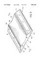
- FIG. 3is a perspective view of a road marker having the retroreflective structure of the present invention.
- FIG. 4is a cross-sectional view of the road marker and retroreflective structure shown in FIG. 5.
- FIG. 5is a cross-sectional view of another embodiment of the road marker and retroreflective marker.
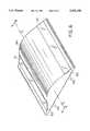
- FIG. 6is a perspective view of another embodiment of a road marker and retroreflective structure.
- the present inventionrelates to a retroreflective structure that has a window side and a facet side.
- the facet sideincludes a stepped structure having arrays of retroreflective elements on the risers of the structure.
- the arraysare cube-corner prisms that have a metalized surface.
- the present inventionalso relates to a method for forming the retroreflective structure.
- the structureis formed by polymerizing or molding a composition in a mold that has a facet side that is tiered with steps and risers.
- the risershave arrays of retroreflective elements, which, preferably, are cube-corner prisms.
- the arrayscan be coated with a metalized coating.
- the present inventionalso includes a road marker with a retroreflective structure that is attached.
- the road markerhas a raised rumple portion of which the portion projects upwardly from the base of the structure.
- the rumple portionhas at least one concave surface for attaching the structure.
- the structurehas a window side and facet side.
- the facet sideis tiered with steps and risers.
- the risershave an array of retroreflective elements, which can be cube-corner prisms.
- the present inventionhas many advantages that include allowing a substantial amount of incidental light striking a low angle to the surface of a structure to be retroreflected.
- the structurecan be applied to a surface of a road marker having a surface with a low profile to allow automobiles to drive over the road marker while allowing incidental light from a distant automobile to be retroreflected.
- Retroreflective structure 10has window side 12 and facet side 14.
- Window side 12can be a flat surface.
- Facet side 14has a tiered structure 16 formed of a tread portion 18 and a riser portion 20 extending at an angle to the tread portion 18.
- the face of the riser portion 20is formed into an array 22 of retroreflective elements 24.
- Array 22can be comprised of cube-corner prism elements, bar prisms elements, frensel lens elements, etc.
- each riser portion 20has four rows of cube-corner prisms elements 24 with a cube-side length 26 in the range of between about 0.004 and 0.02 inches.
- Retroreflected light intensity off a surfaceis typically greatest at the optical axis which is where the angle of incidence of the light source to the surface is ninety degrees. Therefore, light received by an array of elements has the greatest retroreflectivity where the elements are positioned in a manner to allow the light to be retroreflected at ninety degrees to the array.
- Tread portion 18has a depth (d) which is the distance from the back of an array of elements on one level to the back of an array of elements on the next level.
- the riser height (h)is the distance from the level of one tread portion 18 to the next tread portion 18.
- the ratio of riser height (h) to tread depth (d)is dependent on the index of refraction of the material selected for array 22 and the angle ⁇ at which light that is to be retroreflected is incident to the surface of window side 12.
- the retroreflective structurecan be attached to a road marker at angle ⁇ between the road pavement and window side surface 12 for retroreflecting the light received from headlights.
- angle ⁇is about 30° in relation to the road pavement.
- light ray 28 from a sourcesuch as from a distance automobile, is bent as it passes through the air/surface interface to an angle ⁇ from the normal 30 to the surface of window side 12.
- the arrays 22 of retroreflective elementsare positioned perpendicularly to the optical axis 32 of light passing through retroreflective structure 10.
- retroreflective structure 10is comprised of a polymer having an index of refraction of about 1.49
- the light ray 28would be bent to an angle of about 35.4° from the normal 30 if angle ⁇ is 30°.
- the depth of tread portion 18can be calculated by the Equation 1, which has the formula:
- the depth of tread portioncan be calculated using Equation 1.
- riser portions 20can be parallel with each other.
- retroreflective structure 10can be arced slightly, thereby having riser portions 20 not parallel to allow for changes in angle ⁇ of light ray 24, such as with an approaching automobile, so that the refracted light rays are parallel to the optical axis of a substantial number of the retroreflective elements.
- the depth of tread portion 18is in the range of between about 0.002 and 0.03 inches, and the height of riser portion 20 is in the same range of between about 0.002 and 0.03 inches.
- retroreflective structure 10is formed of a polymer that can recover substantially its original shape after a deforming force has been removed.
- a polymercan be elastomeric or rigid.
- the polymeris sufficiently resilient to recover to its original configuration after having been compressed.
- the polymeris transparent to visible light and is composed of a polymer, such as polyurethane, polyisobutylene, polybutadiene, polyvinyl chloride or polyvinylidene chloride.
- the polymercan be a copolymer or terpolymer, such as poly(ethylene-propylene), poly(styrene-butadiene), poly(vinyl acetate-vinyl chloride) and poly(ethylenevinyl acetate).
- the polymercan be selected from a wide variety of polymers that are considered rigid. These polymers include the polymers of urethane, acrylic acid esters, cellulose esters, ethylenically unsaturated nitriles, hard epoxy acrylates, etc. Other polymers include polycarbonates, polyesters and polyolefins, acrylated silanes, hard polyester urethane acrylates.
- the polymercan be cast in a prismatic mold with a monomer or oligomer polymerization initiated by ultraviolet radiation.
- retroreflective structure 10can be formed of a composition having an index of refraction in the range of between about 1.49 and 1.56.
- Retroreflective structure 10can have a thickness (t), shown in FIG. 2, in the range of between about 0.5 and 30 mils (0.0005 and 0.03 inches). In a preferred embodiment, the thickness is in the range of between about 1 and 10 mils (0.001 and 0.01 inches). The selected thickness is dependent upon the method of fabrication, the polymer and the characteristics desired for the retroreflective structure.
- a mold for forming the retroreflective structure 10can be formed from a master negative die on a flat surface of a metal plate or other suitable material.
- the moldis formed of a polycarbonate polymer.
- To form the cube-cornersthree series of parallel equidistance intersecting V-shaped grooves sixty degrees apart are inscribed in a flat plate, creating a positive configuration.
- Another flat plate of negative configuration, usually made by electroformingis then cut in parallel slits, thereby forming a series of parallel plates that can be offset to form a plurality of tiers which are stepped, wherein the face of each riser has the array of retroreflective elements.
- the retroreflective structurecan be cast from the die.
- individual sheets of metalcan be formed having a thickness of about the height of the face.
- a structure for forming retroreflective elementsis inscribed on one side edge of each sheet. The sheets are then placed in parallel and the arrays are offset by the desired depth of the tread portions 20.
- the retroreflective structure 10can be attached to a surface by an adhesive or only at certain points on the surface, such as in a grid pattern, thereby allowing an air interface to remain.
- the retroreflective structure 10can be attached by high frequency welding.
- the lines of the gridare spaced about a one half inch or one inch apart and have a width in the range of between about a sixteenth to an eighth of one inch.
- the adhesivecan cause the surface of the prisms elements to wet, thereby destroying the air interface and eliminating the ability of the prism to retroreflect.
- reflective coating 34is preferably deposited on the surface of the retroreflective elements.
- the reflective coating 34is formed by sputtering aluminum, silver or gold or by vacuum metallization.
- metal lacquers, dielectric coatings and other specular coating materialscan be employed.
- FIGS. 3 and 4illustrate the general shape of a preferred embodiment of a road marker 40 for use with the present invention.
- the body of the road markeris disclosed in U.S. patent application Ser. No. 08/092,708, filed Jul. 15, 1993, applicants Peter A. Spear et al. (now U.S. Pat. No. 5,392,728 issued Feb. 28, 1995), the teachings of which are herein incorporated by reference.
- the road marker 40has a constant cross section from one end to the other along a longitudinal center line A--A. The constant cross section allows the illustrated road marker 40 to be extruded using conventional nonmetallic, i.e., plastic, extrusion technology, and sheared to any desired length.
- Road marker 40which is illustrated in FIG.
- the base 42includes a base 42 and raised rumple portion 46.
- the bottom of the base 42is substantially planar and of rectangular shape. A large bottom allows a road marker to be strongly attached to a road surface by any suitable adhesive, such as epoxy, butyl, or hot melt bituminous adhesive.
- the bottom of the base 42can include a series of parallel grooves 44.
- Grooves 44are disposed adjacent and parallel to one another. Grooves 44 also lie parallel to the longitudinal center line A--A. Grooves 44 extend the entire length of the marker 40 and have an arcuate cross section. When compared to a base with a flat bottom, the arcuate cross section increases the size of the adhesion surface of the bottom, thereby allowing the base to be better attached to a roadway. Arcuate grooves have even a larger surface area than do the V-shaped grooves, thereby providing better road attachment.
- the raised rumple portion 46is comprised of two regions, a center scalloped recess 48 and concave curved edges 50,52. Because the concave curved edges can be identical, the road marker 40 can be positioned such that either edge can form the traffic facing edge when the marker is used on a road with traffic moving in a single direction, or both edges can form traffic facing edges when the marker is used on a road with traffic coming from opposite directions.
- the center scalloped recess and the concave curved edgescause the raised rumple portion 46 to have the cross-sectional shape of a pair of humps 54,56.
- the humpsare located between the centered scalloped recess 48 and the curved edges 50,52.
- the cross-sectional shapeis constant throughout the length of the road marker 40 along centerline A--A. Because the primary function of the scalloped recess 48 is to reduce the weight of the road marker 40, the exact shape of this recess is not critical. While shown as curved, the scalloped recess 48 could have some other form.
- One important aspect of the scalloped recess 48is its average radius of curvature.
- the average radius of curvature of the scalloped recess 48should be substantially less than the radius of curvature of smaller-sized automobile tires. Since smaller-sized automobile tires have a radius of curvature of about thirteen inches, this means that the average radius of curvature of the scalloped recess 48 should be substantially less than thirteen inches.
- An average radius of curvature substantially less than the radius of curvature of smaller-sized automobile tiresprevents automobile and other vehicle tires from seating in the recess 48 when a tire passes over the road marker 40.
- Reflective structure 10is added to the surfaces of the concave curved edges 50,52 of a road marker. More specifically, the embodiments of the invention shown in FIGS. 3 and 4 include a retroreflective structure 10 applied to and held in place with the surfaces of the concave curved edges 50,52.
- the facet side 14 of retroreflective structure 10is attached atop the surface of the concave curved edges 50,52 by a suitable adhesive, the angle ⁇ of the window side 12 of retroreflective structure 10 to the pavement is sufficient to allow the light rays from a distance automobile to bend enough so that it can be parallel to the optical axis of the array of retroreflective elements.
- FIG. 5illustrates that the concave curved edges 50,52 can include an undercut region 60 for receiving the retroreflective structure 10. Placing the retroreflective structure 10 in undercut region 58 provides additional protection against tire abrasion.
- the radius of curvature of the concave curved edge 50 of the road marker 40is such that when a tire impacts the hump 54 that occurs where the end of the concave curved edge 50 meets the scalloped recess 48, the tire does not impact the surface of the concave curved edge 50. As a result, the tire does not ride on the surface of the concave curved edge 50 and, thus, does not impinge on retroreflective structure 10 located on the surface of the concave curved edge 50. In essence, the retroreflective structure 10 lies in a gap between the surface of the concave curved edge 50 and the surface of tires impacting road marker 40.
- retroreflective structure 10either located directly on the surface of concave curved edge 50, as shown in FIGS. 3 and 4, or located in undercut region 58 of the concave curved edge, as shown in FIG. 5.
- FIG. 6illustrates yet another embodiment of a road marker with retroreflective structure 10.
- a convex protrusion 64is located therebetween.
- the road markeris constant along its longitudinal axis B--B and the concave curved edges 60,62 have a constant or variable radius of curvature sized such that tires hitting the concave curved edges do not apply friction to strips of retroreflective structure 10 applied to the concave curved edges.
- the convex protrusion 64rises upwardly between the concave curved edges 60,62.
- the radius of curvature of the convex protrusionlies in the range of between about two and ten inches, with about 3.5 inches being preferred.
- the base of the marker illustrated in FIG. 6is similar to the base of the previously described markers.
- the baseincludes a plurality of parallel grooves 66.
- the illustrated road markersare formed with a constant cross section.
- the illustrated embodimentscan be formed by extruding a suitable plastic through a die having a shape corresponding to the desired cross-sectional configuration. The extrudate is then cured and hardened.
- the manufacture of road markers using an extrusion methodgreatly decreases the cost of such markers.
- extrusionallows road markers performed in accordance with the present invention to be easily manufactured in varying length. This allows the embodiments of the invention to be used as "rumple" strips, as well as spaced-apart road markers.
- the continuous nature of the baseallows less adhesive to be used to create a strong bond between the base of the roadway marker and a road surface.
- embodiments of the inventionare made by extrusion, embodiments of the invention can be molded, if desired. Damaged and/or eroded retroreflective structure can be replaced, provided the bodies of markers formed in accordance with the invention remain intact, making embodiments of the invention reusable and, thus, more economical.
Landscapes
- Physics & Mathematics (AREA)
- Engineering & Computer Science (AREA)
- Architecture (AREA)
- Civil Engineering (AREA)
- Structural Engineering (AREA)
- General Physics & Mathematics (AREA)
- Optics & Photonics (AREA)
- Road Signs Or Road Markings (AREA)
- Optical Elements Other Than Lenses (AREA)
- Illuminated Signs And Luminous Advertising (AREA)
Abstract
Description
tan θ=depth of tread portion/height of riser portion (1)
Claims (19)
Priority Applications (7)
| Application Number | Priority Date | Filing Date | Title |
|---|---|---|---|
| US08/336,467US5501545A (en) | 1994-11-09 | 1994-11-09 | Retroreflective structure and road marker employing same |
| US08/459,334US5660768A (en) | 1994-11-09 | 1995-06-02 | Method for forming a retroreflective structure |
| EP95939742AEP0791181A1 (en) | 1994-11-09 | 1995-11-02 | A retroreflective structure and method for forming the structure |
| CN95196160ACN1109255C (en) | 1994-11-09 | 1995-11-02 | A retroreflective structure and method for forming the structure |
| JP8516138AJPH10508957A (en) | 1994-11-09 | 1995-11-02 | Retroreflective structure and method of manufacturing the same |
| PCT/US1995/014298WO1996015465A1 (en) | 1994-11-09 | 1995-11-02 | A retroreflective structure and method for forming the structure |
| TW086215420UTW345212U (en) | 1994-11-09 | 1995-11-09 | Retroreflective structure |
Applications Claiming Priority (1)
| Application Number | Priority Date | Filing Date | Title |
|---|---|---|---|
| US08/336,467US5501545A (en) | 1994-11-09 | 1994-11-09 | Retroreflective structure and road marker employing same |
Related Child Applications (1)
| Application Number | Title | Priority Date | Filing Date |
|---|---|---|---|
| US08/459,334DivisionUS5660768A (en) | 1994-11-09 | 1995-06-02 | Method for forming a retroreflective structure |
Publications (1)
| Publication Number | Publication Date |
|---|---|
| US5501545Atrue US5501545A (en) | 1996-03-26 |
Family
ID=23316218
Family Applications (2)
| Application Number | Title | Priority Date | Filing Date |
|---|---|---|---|
| US08/336,467Expired - LifetimeUS5501545A (en) | 1994-11-09 | 1994-11-09 | Retroreflective structure and road marker employing same |
| US08/459,334Expired - LifetimeUS5660768A (en) | 1994-11-09 | 1995-06-02 | Method for forming a retroreflective structure |
Family Applications After (1)
| Application Number | Title | Priority Date | Filing Date |
|---|---|---|---|
| US08/459,334Expired - LifetimeUS5660768A (en) | 1994-11-09 | 1995-06-02 | Method for forming a retroreflective structure |
Country Status (6)
| Country | Link |
|---|---|
| US (2) | US5501545A (en) |
| EP (1) | EP0791181A1 (en) |
| JP (1) | JPH10508957A (en) |
| CN (1) | CN1109255C (en) |
| TW (1) | TW345212U (en) |
| WO (1) | WO1996015465A1 (en) |
Cited By (20)
| Publication number | Priority date | Publication date | Assignee | Title |
|---|---|---|---|---|
| US5751226A (en)* | 1996-12-02 | 1998-05-12 | Hretsina; Gary | Taxiway marker |
| US5927897A (en)* | 1995-07-14 | 1999-07-27 | Attar; Adil | Housingless abrasion resistant pavement marker |
| US6143224A (en)* | 1995-05-18 | 2000-11-07 | Reflexite Corporation | Method for forming a retroreflective sheeting |
| RU2164997C2 (en)* | 1998-09-09 | 2001-04-10 | Мияма Когио Кабусики Кайся | Stairs provided with reflectors |
| US6398287B1 (en) | 1998-02-20 | 2002-06-04 | Reflexite Corporation | Retroreflective reinforcement webbing applied to an outer side of a tarpaulin |
| US6835023B1 (en) | 2000-12-01 | 2004-12-28 | John D. Paterson | Reflective traffic panel |
| US20050270175A1 (en)* | 2003-09-18 | 2005-12-08 | Spot Devices, Inc. | Methods, systems and devices related to road mounted indicators for providing visual indications to approaching traffic |
| US20100003079A1 (en)* | 2008-07-02 | 2010-01-07 | Roadvision Technologies, Inc. | Method of Installing Depressible Pavement Marker |
| US20100104362A1 (en)* | 2005-02-14 | 2010-04-29 | Ron Hicks | Surface Stripe |
| US20120325585A1 (en)* | 2011-06-24 | 2012-12-27 | Trans-Tech LLC | Reflective Friction-Enhancement For Surfaces |
| US9010945B2 (en) | 2010-10-22 | 2015-04-21 | Svv Technology Innovations, Inc. | Retroreflective lenticular arrays |
| US20150303581A1 (en)* | 2014-04-18 | 2015-10-22 | Martin Joseph Bodo | Course guidance for a self-driving vehicle |
| US20160275791A1 (en)* | 2015-03-16 | 2016-09-22 | International Business Machines Corporation | Syncronized traffic warning signal system |
| US10416304B2 (en)* | 2017-03-06 | 2019-09-17 | The Aerospace Corporation | Automobile accident mitigation technique |
| US10444343B2 (en)* | 2016-07-26 | 2019-10-15 | Alpha Networks Inc. | Mobile navigation method and system |
| US10794021B1 (en)* | 2020-06-03 | 2020-10-06 | Mark Joseph O'Neill | Retroreflective traffic stripe |
| US10901082B2 (en)* | 2017-11-09 | 2021-01-26 | Fractal Antenna Systems, Inc. | Road identification system using enhanced cross-section targets |
| US11011082B2 (en)* | 2017-05-16 | 2021-05-18 | Promedica Health System, Inc. | Stairway safety device |
| US11124932B1 (en)* | 2021-04-30 | 2021-09-21 | Mark Joseph O'Neill | Retroreflective traffic stripe for both dry and wet weather conditions |
| US20220219766A1 (en)* | 2021-01-12 | 2022-07-14 | Honda Motor Co., Ltd. | Surface pattern for a vehicle |
Families Citing this family (6)
| Publication number | Priority date | Publication date | Assignee | Title |
|---|---|---|---|---|
| US6861134B1 (en) | 2001-04-02 | 2005-03-01 | Omnova Solutions Inc. | Retroreflective articles of nanoporous construction and method for the manufacture thereof |
| US20070177269A1 (en)* | 2006-02-02 | 2007-08-02 | Depaoli Gerald | Safety Light or Reflector for Front and Side Edge of Snow Plow |
| US7374297B2 (en)* | 2006-03-31 | 2008-05-20 | Reflexite Corporation | Conformable retroreflective film structure |
| KR101060431B1 (en) | 2006-10-03 | 2011-08-29 | 김봉주 | Retroreflective element and retroreflective body having same |
| KR20090067654A (en)* | 2007-12-21 | 2009-06-25 | 김봉주 | Retroreflective element and retroreflective body having same |
| CN103837916B (en)* | 2014-03-19 | 2017-01-18 | 张家港康得新光电材料有限公司 | Retro-reflective film |
Citations (43)
| Publication number | Priority date | Publication date | Assignee | Title |
|---|---|---|---|---|
| US1707432A (en)* | 1926-09-27 | 1929-04-02 | Knute E Erickson | Traffic safety warning signal |
| US2664065A (en)* | 1952-11-28 | 1953-12-29 | Mernard A Thompson | Highway signaling device |
| US2948191A (en)* | 1956-06-06 | 1960-08-09 | Cataphote Corp | Retroreflecting surface |
| US2991698A (en)* | 1955-08-22 | 1961-07-11 | Leubaz Ernest | Safety marker |
| US3277800A (en)* | 1961-09-01 | 1966-10-11 | Botts Line Inc | Traffic marker |
| US3319542A (en)* | 1962-12-26 | 1967-05-16 | Chandler Ide | Controlled divergency reflector |
| US3392639A (en)* | 1966-10-12 | 1968-07-16 | Elastic Stop Nut Corp | Pavement marker for day and night visibility |
| US3417959A (en)* | 1966-11-14 | 1968-12-24 | Minnesota Mining & Mfg | Die for forming retro-reflective article |
| US3541216A (en)* | 1968-08-26 | 1970-11-17 | Chris Craft Ind Inc | Process for making an embossed product |
| US3588222A (en)* | 1967-11-09 | 1971-06-28 | Harold A Julius | Road reflectors |
| US3684348A (en)* | 1970-09-29 | 1972-08-15 | Rowland Dev Corp | Retroreflective material |
| US3689346A (en)* | 1970-09-29 | 1972-09-05 | Rowland Dev Corp | Method for producing retroreflective material |
| US3790293A (en)* | 1972-10-04 | 1974-02-05 | Amerace Esna Corp | Pavement marker reflector member and assembly |
| US3810804A (en)* | 1970-09-29 | 1974-05-14 | Rowland Dev Corp | Method of making retroreflective material |
| US3811983A (en)* | 1972-06-23 | 1974-05-21 | Rowland Dev Corp | Method for producing retroreflective sheeting |
| US3830682A (en)* | 1972-11-06 | 1974-08-20 | Rowland Dev Corp | Retroreflecting signs and the like with novel day-night coloration |
| US3924958A (en)* | 1972-12-21 | 1975-12-09 | Rowland Dev Corp | Highway retroreflecting marker |
| US3935359A (en)* | 1972-06-23 | 1976-01-27 | Rowland Development Corporation | Retroreflective sheeting and method and apparatus for producing same |
| US3936208A (en)* | 1973-04-03 | 1976-02-03 | Dunlop Limited | Reflector stud |
| US3938903A (en)* | 1975-01-03 | 1976-02-17 | Ferro Corporation | Highway roadmarker with studded bottom |
| US3975083A (en)* | 1974-07-24 | 1976-08-17 | Reflexite Corporation | Wide angle retroreflector assembly and method of making same |
| US3992080A (en)* | 1975-06-13 | 1976-11-16 | Reflexite Corporation | Retroreflective sheet material with controlled stretch and method of making same |
| US4040760A (en)* | 1974-06-12 | 1977-08-09 | Wyckoff Charles W | Direction-indicating surface marking apparatus for roadways and the like |
| US4076383A (en)* | 1975-11-26 | 1978-02-28 | Ferro Corporation | Multi-sided retroreflector |
| US4145112A (en)* | 1977-07-14 | 1979-03-20 | Minnesota Mining And Manufacturing Company | Low-profile raised retroreflective sheeting |
| US4182548A (en)* | 1977-07-05 | 1980-01-08 | Ferro Corporation | Retroreflective marking tape |
| US4202600A (en)* | 1978-04-24 | 1980-05-13 | Avery International Corporation | Diced retroreflective sheeting |
| US4234265A (en)* | 1977-02-28 | 1980-11-18 | Otis George A | Light transmitting roadway marker |
| US4243618A (en)* | 1978-10-23 | 1981-01-06 | Avery International Corporation | Method for forming retroreflective sheeting |
| US4244683A (en)* | 1979-09-20 | 1981-01-13 | Reflexite Corporation | Apparatus for compression molding of retroreflective sheeting |
| US4279471A (en)* | 1979-12-31 | 1981-07-21 | Reflexite Corporation | Retroreflector for road surfaces |
| US4332847A (en)* | 1979-09-20 | 1982-06-01 | Relfexite Corporation | Method for compression molding of retroreflective sheeting and sheeting produced thereby |
| US4362425A (en)* | 1980-12-16 | 1982-12-07 | Dixon Byron P | Road marker |
| US4521129A (en)* | 1983-06-17 | 1985-06-04 | Minnesota Mining And Manufacturing Company | Elastomeric pavement marker having improved configuration |
| US4555161A (en)* | 1984-02-16 | 1985-11-26 | Reflexite Corporation | Encapsulated retroreflective material and method of making same |
| US4557624A (en)* | 1983-09-09 | 1985-12-10 | Walker Floyd E | Snow plowable pavement marker |
| US4801193A (en)* | 1988-03-04 | 1989-01-31 | Reflexite Corporation | Retroreflective sheet material and method of making same |
| US5132841A (en)* | 1990-12-14 | 1992-07-21 | Bennett Reginald B | Ribbed reflector |
| US5171624A (en)* | 1990-06-01 | 1992-12-15 | Reflexite Corporation | Retroreflective microprismatic material and method of making same |
| US5229882A (en)* | 1990-05-16 | 1993-07-20 | Reflexite Corporation | Colored retroreflective sheeting and method of making same |
| US5264063A (en)* | 1990-05-16 | 1993-11-23 | Reflexite Corporation | Method for making flexible retroreflective sheet material |
| US5340231A (en)* | 1991-12-10 | 1994-08-23 | Stimsonite Corporation | Pavement marker |
| US5392728A (en)* | 1991-05-02 | 1995-02-28 | Davidson Plastic Company | Roadway markers with concave curved edges |
Family Cites Families (7)
| Publication number | Priority date | Publication date | Assignee | Title |
|---|---|---|---|---|
| US3409344A (en)* | 1967-03-03 | 1968-11-05 | Reflex Corp Canada Ltd | Roadway reflectors |
| US3836226A (en)* | 1973-07-23 | 1974-09-17 | J Cechetini | Reflective pavement marker |
| FR2450906A1 (en)* | 1979-03-05 | 1980-10-03 | Couturier Jean | Reflecting rod stud for marking carriageways - has shallow lead in angle and anti-skid surfaces for safety of motorcycles |
| DK112284A (en)* | 1983-03-22 | 1984-09-23 | Semperit Ag | COURSE RAILWAY ELEMENT |
| US4842784A (en)* | 1986-07-30 | 1989-06-27 | Miyama Kogyo Kabushiki Kaisha | Method of manufacturing a climbing step with embedded reflection plate |
| US4797024A (en)* | 1986-09-29 | 1989-01-10 | Pac-Tec, Inc. | Abrasive resistant pavement marker |
| US5327850A (en)* | 1991-05-02 | 1994-07-12 | Davidson Plastics Company | Roadway marker |
- 1994
- 1994-11-09USUS08/336,467patent/US5501545A/ennot_activeExpired - Lifetime
- 1995
- 1995-06-02USUS08/459,334patent/US5660768A/ennot_activeExpired - Lifetime
- 1995-11-02CNCN95196160Apatent/CN1109255C/ennot_activeExpired - Fee Related
- 1995-11-02EPEP95939742Apatent/EP0791181A1/ennot_activeWithdrawn
- 1995-11-02WOPCT/US1995/014298patent/WO1996015465A1/ennot_activeApplication Discontinuation
- 1995-11-02JPJP8516138Apatent/JPH10508957A/enactivePending
- 1995-11-09TWTW086215420Upatent/TW345212U/enunknown
Patent Citations (43)
| Publication number | Priority date | Publication date | Assignee | Title |
|---|---|---|---|---|
| US1707432A (en)* | 1926-09-27 | 1929-04-02 | Knute E Erickson | Traffic safety warning signal |
| US2664065A (en)* | 1952-11-28 | 1953-12-29 | Mernard A Thompson | Highway signaling device |
| US2991698A (en)* | 1955-08-22 | 1961-07-11 | Leubaz Ernest | Safety marker |
| US2948191A (en)* | 1956-06-06 | 1960-08-09 | Cataphote Corp | Retroreflecting surface |
| US3277800A (en)* | 1961-09-01 | 1966-10-11 | Botts Line Inc | Traffic marker |
| US3319542A (en)* | 1962-12-26 | 1967-05-16 | Chandler Ide | Controlled divergency reflector |
| US3392639A (en)* | 1966-10-12 | 1968-07-16 | Elastic Stop Nut Corp | Pavement marker for day and night visibility |
| US3417959A (en)* | 1966-11-14 | 1968-12-24 | Minnesota Mining & Mfg | Die for forming retro-reflective article |
| US3588222A (en)* | 1967-11-09 | 1971-06-28 | Harold A Julius | Road reflectors |
| US3541216A (en)* | 1968-08-26 | 1970-11-17 | Chris Craft Ind Inc | Process for making an embossed product |
| US3684348A (en)* | 1970-09-29 | 1972-08-15 | Rowland Dev Corp | Retroreflective material |
| US3689346A (en)* | 1970-09-29 | 1972-09-05 | Rowland Dev Corp | Method for producing retroreflective material |
| US3810804A (en)* | 1970-09-29 | 1974-05-14 | Rowland Dev Corp | Method of making retroreflective material |
| US3811983A (en)* | 1972-06-23 | 1974-05-21 | Rowland Dev Corp | Method for producing retroreflective sheeting |
| US3935359A (en)* | 1972-06-23 | 1976-01-27 | Rowland Development Corporation | Retroreflective sheeting and method and apparatus for producing same |
| US3790293A (en)* | 1972-10-04 | 1974-02-05 | Amerace Esna Corp | Pavement marker reflector member and assembly |
| US3830682A (en)* | 1972-11-06 | 1974-08-20 | Rowland Dev Corp | Retroreflecting signs and the like with novel day-night coloration |
| US3924958A (en)* | 1972-12-21 | 1975-12-09 | Rowland Dev Corp | Highway retroreflecting marker |
| US3936208A (en)* | 1973-04-03 | 1976-02-03 | Dunlop Limited | Reflector stud |
| US4040760A (en)* | 1974-06-12 | 1977-08-09 | Wyckoff Charles W | Direction-indicating surface marking apparatus for roadways and the like |
| US3975083A (en)* | 1974-07-24 | 1976-08-17 | Reflexite Corporation | Wide angle retroreflector assembly and method of making same |
| US3938903A (en)* | 1975-01-03 | 1976-02-17 | Ferro Corporation | Highway roadmarker with studded bottom |
| US3992080A (en)* | 1975-06-13 | 1976-11-16 | Reflexite Corporation | Retroreflective sheet material with controlled stretch and method of making same |
| US4076383A (en)* | 1975-11-26 | 1978-02-28 | Ferro Corporation | Multi-sided retroreflector |
| US4234265A (en)* | 1977-02-28 | 1980-11-18 | Otis George A | Light transmitting roadway marker |
| US4182548A (en)* | 1977-07-05 | 1980-01-08 | Ferro Corporation | Retroreflective marking tape |
| US4145112A (en)* | 1977-07-14 | 1979-03-20 | Minnesota Mining And Manufacturing Company | Low-profile raised retroreflective sheeting |
| US4202600A (en)* | 1978-04-24 | 1980-05-13 | Avery International Corporation | Diced retroreflective sheeting |
| US4243618A (en)* | 1978-10-23 | 1981-01-06 | Avery International Corporation | Method for forming retroreflective sheeting |
| US4332847A (en)* | 1979-09-20 | 1982-06-01 | Relfexite Corporation | Method for compression molding of retroreflective sheeting and sheeting produced thereby |
| US4244683A (en)* | 1979-09-20 | 1981-01-13 | Reflexite Corporation | Apparatus for compression molding of retroreflective sheeting |
| US4279471A (en)* | 1979-12-31 | 1981-07-21 | Reflexite Corporation | Retroreflector for road surfaces |
| US4362425A (en)* | 1980-12-16 | 1982-12-07 | Dixon Byron P | Road marker |
| US4521129A (en)* | 1983-06-17 | 1985-06-04 | Minnesota Mining And Manufacturing Company | Elastomeric pavement marker having improved configuration |
| US4557624A (en)* | 1983-09-09 | 1985-12-10 | Walker Floyd E | Snow plowable pavement marker |
| US4555161A (en)* | 1984-02-16 | 1985-11-26 | Reflexite Corporation | Encapsulated retroreflective material and method of making same |
| US4801193A (en)* | 1988-03-04 | 1989-01-31 | Reflexite Corporation | Retroreflective sheet material and method of making same |
| US5229882A (en)* | 1990-05-16 | 1993-07-20 | Reflexite Corporation | Colored retroreflective sheeting and method of making same |
| US5264063A (en)* | 1990-05-16 | 1993-11-23 | Reflexite Corporation | Method for making flexible retroreflective sheet material |
| US5171624A (en)* | 1990-06-01 | 1992-12-15 | Reflexite Corporation | Retroreflective microprismatic material and method of making same |
| US5132841A (en)* | 1990-12-14 | 1992-07-21 | Bennett Reginald B | Ribbed reflector |
| US5392728A (en)* | 1991-05-02 | 1995-02-28 | Davidson Plastic Company | Roadway markers with concave curved edges |
| US5340231A (en)* | 1991-12-10 | 1994-08-23 | Stimsonite Corporation | Pavement marker |
Non-Patent Citations (4)
| Title |
|---|
| "Retroreflective Raised Pavement Markers: A Two-Year Field Evaluation in Texas," Research Report 1946-3F, Texas Transportation Institute, The Texas A&M University System, College Station, Texas. |
| Retroreflective Raised Pavement Markers: A Two Year Field Evaluation in Texas, Research Report 1946 3F, Texas Transportation Institute, The Texas A&M University System, College Station, Texas.* |
| U.S. Application Serial Number 08/092,708, "Roadway Markers with Concave Curved Edges" by Spear et al. |
| U.S. Application Serial Number 08/092,708, Roadway Markers with Concave Curved Edges by Spear et al.* |
Cited By (32)
| Publication number | Priority date | Publication date | Assignee | Title |
|---|---|---|---|---|
| US6143224A (en)* | 1995-05-18 | 2000-11-07 | Reflexite Corporation | Method for forming a retroreflective sheeting |
| US6231797B1 (en) | 1995-05-18 | 2001-05-15 | Reflexite Corporation | Method for forming a retroreflective sheeting |
| US5927897A (en)* | 1995-07-14 | 1999-07-27 | Attar; Adil | Housingless abrasion resistant pavement marker |
| US5751226A (en)* | 1996-12-02 | 1998-05-12 | Hretsina; Gary | Taxiway marker |
| US6398287B1 (en) | 1998-02-20 | 2002-06-04 | Reflexite Corporation | Retroreflective reinforcement webbing applied to an outer side of a tarpaulin |
| RU2164997C2 (en)* | 1998-09-09 | 2001-04-10 | Мияма Когио Кабусики Кайся | Stairs provided with reflectors |
| US6835023B1 (en) | 2000-12-01 | 2004-12-28 | John D. Paterson | Reflective traffic panel |
| US7859431B2 (en) | 2003-09-18 | 2010-12-28 | Spot Devices, Inc. | Methods, systems and devices related to road mounted indicators for providing visual indications to approaching traffic |
| US20050270175A1 (en)* | 2003-09-18 | 2005-12-08 | Spot Devices, Inc. | Methods, systems and devices related to road mounted indicators for providing visual indications to approaching traffic |
| US7688222B2 (en) | 2003-09-18 | 2010-03-30 | Spot Devices, Inc. | Methods, systems and devices related to road mounted indicators for providing visual indications to approaching traffic |
| US20100104362A1 (en)* | 2005-02-14 | 2010-04-29 | Ron Hicks | Surface Stripe |
| US9534351B2 (en)* | 2008-07-02 | 2017-01-03 | Roadvision Technologies, Inc. | Method of installing depressible pavement marker |
| US20100003079A1 (en)* | 2008-07-02 | 2010-01-07 | Roadvision Technologies, Inc. | Method of Installing Depressible Pavement Marker |
| US10443198B2 (en) | 2008-07-02 | 2019-10-15 | Roadvision Technologies, Inc. | Depressible pavement device |
| US9010945B2 (en) | 2010-10-22 | 2015-04-21 | Svv Technology Innovations, Inc. | Retroreflective lenticular arrays |
| US20120325585A1 (en)* | 2011-06-24 | 2012-12-27 | Trans-Tech LLC | Reflective Friction-Enhancement For Surfaces |
| US20150303581A1 (en)* | 2014-04-18 | 2015-10-22 | Martin Joseph Bodo | Course guidance for a self-driving vehicle |
| US20160275791A1 (en)* | 2015-03-16 | 2016-09-22 | International Business Machines Corporation | Syncronized traffic warning signal system |
| US9666068B2 (en)* | 2015-03-16 | 2017-05-30 | International Business Machines Corporation | Synchronized traffic warning signal system |
| US10444343B2 (en)* | 2016-07-26 | 2019-10-15 | Alpha Networks Inc. | Mobile navigation method and system |
| US10416304B2 (en)* | 2017-03-06 | 2019-09-17 | The Aerospace Corporation | Automobile accident mitigation technique |
| US11011082B2 (en)* | 2017-05-16 | 2021-05-18 | Promedica Health System, Inc. | Stairway safety device |
| US10901082B2 (en)* | 2017-11-09 | 2021-01-26 | Fractal Antenna Systems, Inc. | Road identification system using enhanced cross-section targets |
| US11175400B2 (en)* | 2017-11-09 | 2021-11-16 | Fractal Antenna Systems, Inc. | Road identification system using enhanced cross-section targets |
| US11467279B2 (en)* | 2017-11-09 | 2022-10-11 | Fractal Antenna Systems, Inc. | Road identification system using enhanced cross-section targets |
| US20230058690A1 (en)* | 2017-11-09 | 2023-02-23 | Fractal Antenna Systems, Inc. | Road Identification System Using Enhanced Cross-Section Targets |
| US11808847B2 (en)* | 2017-11-09 | 2023-11-07 | Fractal Antenna Systems, Inc. | Road identification system using enhanced cross-section targets |
| US10794021B1 (en)* | 2020-06-03 | 2020-10-06 | Mark Joseph O'Neill | Retroreflective traffic stripe |
| US11486103B2 (en)* | 2020-06-03 | 2022-11-01 | Mark Joseph O'Neill | Retroreflective traffic stripe 1,000X brighter than the current state of the art |
| US20220219766A1 (en)* | 2021-01-12 | 2022-07-14 | Honda Motor Co., Ltd. | Surface pattern for a vehicle |
| US11618511B2 (en)* | 2021-01-12 | 2023-04-04 | Honda Motor Co., Ltd. | Surface pattern for a vehicle |
| US11124932B1 (en)* | 2021-04-30 | 2021-09-21 | Mark Joseph O'Neill | Retroreflective traffic stripe for both dry and wet weather conditions |
Also Published As
| Publication number | Publication date |
|---|---|
| CN1162998A (en) | 1997-10-22 |
| US5660768A (en) | 1997-08-26 |
| WO1996015465A1 (en) | 1996-05-23 |
| TW345212U (en) | 1998-11-11 |
| EP0791181A1 (en) | 1997-08-27 |
| CN1109255C (en) | 2003-05-21 |
| JPH10508957A (en) | 1998-09-02 |
Similar Documents
| Publication | Publication Date | Title |
|---|---|---|
| US5501545A (en) | Retroreflective structure and road marker employing same | |
| US5491586A (en) | Elastomeric retroreflective structure | |
| US4145112A (en) | Low-profile raised retroreflective sheeting | |
| JP2695924B2 (en) | Retro-reflective pavement marker | |
| JP4078449B2 (en) | Tile retroreflective sheet | |
| US5512219A (en) | Method of casting a microstructure sheet having an array of prism elements using a reusable polycarbonate mold | |
| US4073568A (en) | Retroreflector units with three mutually perpendicular surfaces defining a trihedral angle of a rectangular parallelepiped | |
| US6127020A (en) | Method of making wet retroreflective marking material | |
| EP0835351B1 (en) | High entrance angle retroreflective article and method of making | |
| US6451408B1 (en) | Retroreflective article | |
| JP4225897B2 (en) | Retroreflective device | |
| US6626544B2 (en) | Prismatic retroreflector having a multi-plane facet | |
| US6206525B1 (en) | Miniature micro prism retroreflector | |
| US6703108B1 (en) | Wet retroreflective marking material | |
| US12152354B2 (en) | Anisotropic retroreflective mesh for longitudinal pavement marking articles and methods | |
| JPWO2005059605A1 (en) | Retroreflective sheet and film used for the retroreflective sheet | |
| WO2022216772A1 (en) | Road marking system, method and product | |
| KR830000658B1 (en) | Low embossed retroreflective seating | |
| MXPA03008103A (en) | Vialeta (reflective element) having a low reflective angle. | |
| MXPA97009540A (en) | Retrorreflector article of cubic corners that holds scalene triangles b |
Legal Events
| Date | Code | Title | Description |
|---|---|---|---|
| AS | Assignment | Owner name:REFLEXITE CORPORATION, CONNECTICUT Free format text:ASSIGNMENT OF ASSIGNORS INTEREST;ASSIGNOR:WALTER, HELMUT;REEL/FRAME:007254/0417 Effective date:19941105 | |
| STCF | Information on status: patent grant | Free format text:PATENTED CASE | |
| CC | Certificate of correction | ||
| FPAY | Fee payment | Year of fee payment:4 | |
| FEPP | Fee payment procedure | Free format text:PAYOR NUMBER ASSIGNED (ORIGINAL EVENT CODE: ASPN); ENTITY STATUS OF PATENT OWNER: LARGE ENTITY | |
| FPAY | Fee payment | Year of fee payment:8 | |
| AS | Assignment | Owner name:FLEET NATIONAL BANK, CONNECTICUT Free format text:SECURITY AGREEMENT;ASSIGNOR:REFLEXITE CORPORATION;REEL/FRAME:015242/0221 Effective date:20040923 | |
| FEPP | Fee payment procedure | Free format text:PAT HOLDER NO LONGER CLAIMS SMALL ENTITY STATUS, ENTITY STATUS SET TO UNDISCOUNTED (ORIGINAL EVENT CODE: STOL); ENTITY STATUS OF PATENT OWNER: LARGE ENTITY | |
| REFU | Refund | Free format text:REFUND - PAYMENT OF MAINTENANCE FEE, 12TH YR, SMALL ENTITY (ORIGINAL EVENT CODE: R2553); ENTITY STATUS OF PATENT OWNER: LARGE ENTITY | |
| FPAY | Fee payment | Year of fee payment:12 | |
| FEPP | Fee payment procedure | Free format text:PAYER NUMBER DE-ASSIGNED (ORIGINAL EVENT CODE: RMPN); ENTITY STATUS OF PATENT OWNER: LARGE ENTITY Free format text:PAYOR NUMBER ASSIGNED (ORIGINAL EVENT CODE: ASPN); ENTITY STATUS OF PATENT OWNER: LARGE ENTITY | |
| AS | Assignment | Owner name:ARES CAPITAL CORP., NEW YORK Free format text:SECURITY AGREEMENT;ASSIGNOR:REFLEXITE CORPORATION;REEL/FRAME:022086/0665 Effective date:20090109 | |
| AS | Assignment | Owner name:REFLEXITE CORPORATION, CONNECTICUT Free format text:RELEASE BY SECURED PARTY;ASSIGNOR:ARES CAPITAL CORPORATION;REEL/FRAME:027256/0708 Effective date:20110826 | |
| AS | Assignment | Owner name:REFLEXITE CORPORATION, CONNECTICUT Free format text:RELEASE BY SECURED PARTY;ASSIGNOR:BANK OF AMERICA, N.A., AS SUCCESSOR IN INTEREST TO FLEET NATIONAL BANK;REEL/FRAME:027256/0950 Effective date:20110826 | |
| AS | Assignment | Owner name:BANK OF AMERICA, N.A., CONNECTICUT Free format text:PATENT COLLATERAL ASSIGNMENT AND SECURITY AGREEMENT;ASSIGNOR:REFLEXITE CORPORATION;REEL/FRAME:027354/0839 Effective date:20111207 | |
| AS | Assignment | Owner name:ORAFOL AMERICAS INC., CONNECTICUT Free format text:CHANGE OF NAME;ASSIGNOR:REFLEXITE CORPORATION;REEL/FRAME:029462/0932 Effective date:20121015 |