US5500965A - Cushion - Google Patents
CushionDownload PDFInfo
- Publication number
- US5500965A US5500965AUS08/403,775US40377595AUS5500965AUS 5500965 AUS5500965 AUS 5500965AUS 40377595 AUS40377595 AUS 40377595AUS 5500965 AUS5500965 AUS 5500965A
- Authority
- US
- United States
- Prior art keywords
- tubes
- group
- cushion
- inflated
- inflatable
- Prior art date
- Legal status (The legal status is an assumption and is not a legal conclusion. Google has not performed a legal analysis and makes no representation as to the accuracy of the status listed.)
- Expired - Fee Related
Links
Images

Classifications
- A—HUMAN NECESSITIES
- A61—MEDICAL OR VETERINARY SCIENCE; HYGIENE
- A61G—TRANSPORT, PERSONAL CONVEYANCES, OR ACCOMMODATION SPECIALLY ADAPTED FOR PATIENTS OR DISABLED PERSONS; OPERATING TABLES OR CHAIRS; CHAIRS FOR DENTISTRY; FUNERAL DEVICES
- A61G7/00—Beds specially adapted for nursing; Devices for lifting patients or disabled persons
- A61G7/05—Parts, details or accessories of beds
- A61G7/057—Arrangements for preventing bed-sores or for supporting patients with burns, e.g. mattresses specially adapted therefor
- A61G7/05769—Arrangements for preventing bed-sores or for supporting patients with burns, e.g. mattresses specially adapted therefor with inflatable chambers
- A61G7/05776—Arrangements for preventing bed-sores or for supporting patients with burns, e.g. mattresses specially adapted therefor with inflatable chambers with at least two groups of alternately inflated chambers
- A—HUMAN NECESSITIES
- A61—MEDICAL OR VETERINARY SCIENCE; HYGIENE
- A61G—TRANSPORT, PERSONAL CONVEYANCES, OR ACCOMMODATION SPECIALLY ADAPTED FOR PATIENTS OR DISABLED PERSONS; OPERATING TABLES OR CHAIRS; CHAIRS FOR DENTISTRY; FUNERAL DEVICES
- A61G5/00—Chairs or personal conveyances specially adapted for patients or disabled persons, e.g. wheelchairs
- A61G5/10—Parts, details or accessories
- A61G5/1043—Cushions specially adapted for wheelchairs
- A61G5/1045—Cushions specially adapted for wheelchairs for the seat portion
- A—HUMAN NECESSITIES
- A61—MEDICAL OR VETERINARY SCIENCE; HYGIENE
- A61G—TRANSPORT, PERSONAL CONVEYANCES, OR ACCOMMODATION SPECIALLY ADAPTED FOR PATIENTS OR DISABLED PERSONS; OPERATING TABLES OR CHAIRS; CHAIRS FOR DENTISTRY; FUNERAL DEVICES
- A61G5/00—Chairs or personal conveyances specially adapted for patients or disabled persons, e.g. wheelchairs
- A61G5/10—Parts, details or accessories
- A61G5/1054—Large wheels, e.g. higher than the seat portion
Definitions
- This inventionrelates to controlledly inflatable cushions, particularly inflatable cushions for chairs such as wheelchairs, and to seats for chairs having such cushions and to chairs especially wheelchairs having such seats.
- the tubes of a first groupare a single tube or two or more adjacent tubes and the tubes of the each or other group are two or more spaced apart tubes arranged on opposite sides of the first group of tubes.
- the tubes of each groupare inflatable together by a control unit, so that the group of tubes which support the body weight of a person sitting in the chair alternate with time.
- Reactive hyperaemiaThe change in the region of the user's body supported by the cushion when a group of tubes are deflated encourages "reactive hyperaemia". This is the beneficial increase in blood supply to the region of the user's body no longer supported by the cushion. Reactive hyperaemia is maximised by deflating the tubes quickly to a condition where the pressure at the interface between the deflated tubes and the user's body is low, for example between 5 and 20 mmHg.
- this type of cushionsuffers from the disadvantage that the control unit often needs to switch on to inflate the tubes due to small pressure fluctuations in them. This can cause discomfort to the person sitting on the cushion. It is a particular problem when the cushion is provided with a portable power supply, typically a battery in a wheelchair, as it leads to excessive drainage of the supply.
- a cushion for the seat of a chairhaving at least two groups of cyclically inflatable tubes, each group comprising at least one tube, and control means for inflating and deflating said groups sequentially, said cushion further having a buffer chamber which is maintained by said control means in communication with the inflated group or groups of said cyclically inflated tubes, the buffer chamber comprising at least one inflatable buffer tube providing a part of the sitting surface of the cushion. While this inflatable buffer tube or tubes may be at any suitable location, e.g. the front or back of the cushion, it is most preferable that the buffer chamber is a pair of inflatable buffer tubes at opposite lateral sides of the sitting surface with the sequentially inflated groups of tubes between them.
- the cushioncomprises at least two groups of inflatable tubes arranged for sequential inflation of the respective groups by the control means and arranged in a side-by-side relationship and oriented in a direction corresponding to the front to back direction of the chair seat, the tubes of the first group being a single tube or two or more adjacent tubes and the tubes of the each or other group being two or more spaced apart tubes arranged on opposite sides of the said first group of tubes.
- tubeis used herein for convenience to describe the inflatable flexible material chambers which provide sitting surfaces of the cushion. While such tubes are preferably elongate, they may be square or round as seen in plan view.
- the cushionmay include non-inflatable sitting surfaces.
- the control unitmay be a detachable control unit suitable for governing the inflation and deflation of the inflatable tubes, e.g. a modified form of the control unit disclosed in EP-A-475593. Alternative arrangements will be appreciated by persons skilled in the art.
- the buffer chamberpreferably comprises two or more inflatable buffer tubes parallel to the four tubes arranged on opposite sides of the first and second group of tubes.
- the groups of tubesare connectible to the buffer chamber so that when each group of tubes is inflated, it will be in fluid communication with the buffer chamber. This serves to damp the pressure fluctuations in the cushion and ensures that the control means does not activate a pump unnecessarily.
- the inflated tubesare connected to the buffer chamber and so this increase in pressure is distributed between the buffer chamber and the inflated tubes.
- Thishas the effect of reducing the amount of distortion the inflated tubes suffer and minimising any increase in the pressure at the interface between the user and the deflated tubes.
- Thishas the advantage of maximising the flow of blood to the interface between the user's body and the deflated tubes, encouraging reactive hyperaemia.
- the buffer chambersmooths out minor pressure fluctuations, e.g. those due to the shifting of the sitting person, so that the invention minimises the time during which the control means need to be operated, reducing the power consumption of the cushion. This is particularly important where a portable power supply is used to power the control means, for example in a wheelchair.
- FIG. 1is a plan view of a seat of a wheelchair embodying the invention:
- FIG. 2is an elevation view of the rear of the seat in the direction of arrow A of FIG. 1;
- FIG. 3is a side elevation view of the seat in the direction of arrow B of FIG. 1;
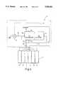
- FIG. 4shows diagrammatically the control means and how they are connected to the cushion
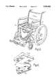
- Fig.5is a perspective view of a wheelchair including the seat.
- FIG. 6is a perspective view of the seat including its control means, showing the connection of the control means to the seat.
- FIGS. 1 to 3show a seat of a wheelchair having a cushion 2 providing the sitting surface i.e. the upper surface contacted by a user.
- the cushionhas six inflatable elongate parallel tubes 4,6,8,10,12,14 arranged side-by-side on a base 22 in an abutting relationship and oriented in a direction corresponding to the front to back direction of the chair seat.
- the size of the cushion 2 and the dimensions of the tubes 4,6,8,10,12,14are chosen to suit the particular use for which the cushion is used.
- the tubesare of vacuum-formed plastics material so as to have a generally rectangular cross-section in their inflated state and adjacent tubes may be bonded together by any suitable means, e.g. adhesive.
- Each of the tubes 4,6,8,10,12,14is formed of fluid impermeable, flexible material, for example a polyurethane.
- the outer tubes 12,14are smaller in cross-section than the inner four tubes 4,6,8,10. The size is limited by the normal requirements of the human body and the requirement to fit into a conventional wheelchair. Typically both the overall side-to-side dimension and the front-to-back dimension of the sitting surface are in the range 35 to 50 cm.
- the cushionis also provided with a non-inflatable resilient support 20 also forming part of the sitting surface and arranged along the front of the cushion 2 in the abutment with the ends of the tubes 4,6,8,10,12,14.
- the supportis made of high density foam plastics with a long memory and has a transverse shape as shown in FIG. 3 including lips 20a,20boverlapping the tubes.
- the six inflatable tubes 4,6,8,10,12,14are supported by a rigid base 22 which is a wooden board having a central recess receiving the inner four tubes 4,6,8,10 bounded by lateral raised rim parts 22a, supporting the outer tubes 12,14 and a front raised rim part 22c supporting the foam support 20.
- the tubes 4,6,8,10,12,14are secured, e.g. by adhesive, to the base 22.
- FIG. 5shows the seat 4, including cushion 2, base 22 and control unit 18, supported on the frame of a conventional wheelchair, which need not be further described.
- the base 22has four keyhole shape slots 23 (see FIG. 6) which receive matching projecting flat-head pins 24 on the integral detachable control unit 18 which contains its own power supply in the form of a battery, an electric motor and an air compressing pump P driven by the motor , an air distributor 30, and actuator 40 and electric controlling circuits for these parts. These parts need not be shown in detail here.
- the base 22therefore carries the whole of the control unit 18.
- this control unit 18is similar to that shown and described in detail in EP-A-475593 to which reference should be made, except that the distributor 30 has additional passages leading to outlet 37c for connecting the buffer tubes 12,14 always to those ones of the sequentially inflated tubes 4,6,8,10 which are at any given time in the inflated state (i.e. the buffer tubes 12,14 are during operation not vented to the atmosphere but always maintained in inflated condition by the control unit).
- the control unit 18 diagrammatically shown in FIG. 4both senses the pressure in the tubes and inflates and deflates them in a pre-determined manner.
- Tubes 4 and 6form a first group of tubes and tubes 8 and 10 form a second group of tubes.
- the two tubes in each groupare inflatable together.
- FIG. 4shows diagrammatically how the control unit 18 is connected to the first and second groups of tubes 4,6,8,10, via respective supply lines 76 from respective outlets 37b of the distributor 30.
- the third outlet 37cis connected to the buffer tubes 12,14 by line 78.
- the pump Psupplies pressurized air to an inlet 37a of the distributor 30 via a line 70.
- a connection 72joins an adaptor 52 of the actuator 40 to the line 70, near the inlet of the distributor 30, so that the actuator senses the pressure at the outlet of the pump P and the inlet 37a of the distributor.
- the line 72includes a flow restricting orifice, of 11/1000 inch diameter, to avoid transfer of pressure surges to the actuator 40.
- a broken line 74indicates an electrical connection from the actuator 40 to the pump P by which the on-off control of the pump P is effected.
- the actuator 40switches the pump P on to raise the pressure in the inflated tubes.
- the buffer tubes 12,14are always connected via the distributor 30 to those ones of the tubes 4,6,8,10 which are inflated, the buffer tubes provides a hysteresis between the pressure in any groups of tubes falling below the minimum value and the pump P switching on. Therefore, the pump P does not activate in response to small fluctuations in pressure in the tubes, which avoids rapid switching on and off of the pump P and minimises the power drain on the supply.
- the increase in pressure in the inflated tubesis distributed between the buffer tubes 12,14 and the inflated group of tubes. This reduces any distortion of the inflated tubes caused by the increase in weight which they support and reduces the pressure at the interface between the deflated tubes and the user's body in contact with them. This distribution of pressure means that the pressure in the inflated tubes and the buffer tubes 12,14 is less likely to exceed the maximum desired pressure.
- the cycleis taken to start at a condition when all of the tubes 4,6,8,10,12,14 are in the fully inflated condition. Then, a first one of the two groups of tubes 4,6,8,10 are deflated by venting to atmosphere, so that the weight of the user is supported on the second group of tubes.
- this increaseis minimised as air from the inflated tubes passes via the distributor 30 into the buffer tubes 12,14, which act as a reservoir or buffer.
- the inflated tubesdo not substantially distort and the pressure at the interface between the user's body is reduced and the deflated group of tubes is minimised.
- the second group of tubesare only allowed to deflate when all four tubes 4,6,8,10 have been in a fully inflated condition for a predetermined amount of time, which is preferably at least four minutes.
- the cycleis completed by re-inflation of the second group of tubes after about a further four minutes, and then maintenance of all tubes in the inflated state for a period (again preferably at least four minutes).
- the deflation step of each group of tubesis rapid, to encourage reactive hyperaemia.
- the operating cycleis repeated so that when a person is seated on the cushion for a long period of time, the areas of the body in contact with the sequentially inflated tubes 4,6,8,10 of the cushion do not support the body weight continuously.
Landscapes
- Health & Medical Sciences (AREA)
- Life Sciences & Earth Sciences (AREA)
- Animal Behavior & Ethology (AREA)
- General Health & Medical Sciences (AREA)
- Public Health (AREA)
- Veterinary Medicine (AREA)
- Nursing (AREA)
- Mattresses And Other Support Structures For Chairs And Beds (AREA)
- Bedding Items (AREA)
- Perforating, Stamping-Out Or Severing By Means Other Than Cutting (AREA)
Abstract
Description
Claims (13)
Applications Claiming Priority (3)
| Application Number | Priority Date | Filing Date | Title |
|---|---|---|---|
| GB9220498 | 1992-09-29 | ||
| GB929220498AGB9220498D0 (en) | 1992-09-29 | 1992-09-29 | Cushion |
| PCT/GB1993/002024WO1994007396A1 (en) | 1992-09-29 | 1993-09-28 | Cushion |
Publications (1)
| Publication Number | Publication Date |
|---|---|
| US5500965Atrue US5500965A (en) | 1996-03-26 |
Family
ID=10722668
Family Applications (1)
| Application Number | Title | Priority Date | Filing Date |
|---|---|---|---|
| US08/403,775Expired - Fee RelatedUS5500965A (en) | 1992-09-29 | 1993-09-28 | Cushion |
Country Status (9)
| Country | Link |
|---|---|
| US (1) | US5500965A (en) |
| EP (1) | EP0666722B1 (en) |
| JP (1) | JPH08501961A (en) |
| AT (1) | ATE151969T1 (en) |
| AU (1) | AU669208B2 (en) |
| CA (1) | CA2145097C (en) |
| DE (1) | DE69310197T2 (en) |
| GB (1) | GB9220498D0 (en) |
| WO (1) | WO1994007396A1 (en) |
Cited By (33)
| Publication number | Priority date | Publication date | Assignee | Title |
|---|---|---|---|---|
| US5657499A (en)* | 1996-01-11 | 1997-08-19 | Sandia Corporation | Reduced energy and volume air pump for a seat cushion |
| EP0872197A2 (en) | 1997-03-24 | 1998-10-21 | Mark Hagopian | A low air loss patient support system providing active feedback pressure sensing and correction capabilities for use as a bed mattress and a wheelchair seating system |
| US5947562A (en)* | 1997-09-19 | 1999-09-07 | Sunrise Medical Hhg Inc. | Quick release seat |
| US6092249A (en)* | 1996-05-28 | 2000-07-25 | Deka Products Limited Partnership | Constant pressure seating system |
| US6216299B1 (en)* | 1999-08-09 | 2001-04-17 | Steven Kohlman | Wheelchair cushion system |
| US20030032507A1 (en)* | 1999-10-14 | 2003-02-13 | Spalding Sports Worldwide, Inc. | Inflatable articles with self-contained inflation mechanism |
| US20030074723A1 (en)* | 2000-06-20 | 2003-04-24 | Buecken Uwe | Inflatable cushion |
| US6560803B2 (en) | 2000-09-05 | 2003-05-13 | Levy Zur | Pressure relief pneumatic area support device and system |
| US6591437B1 (en)* | 1996-04-15 | 2003-07-15 | Kci Licensing, Inc. | Therapeutic mattress and built-in controls |
| US6668405B1 (en) | 2001-01-09 | 2003-12-30 | Aquila Corporation Of Wisconsin | Variable pressure relief inflated cushion |
| US20040048705A1 (en)* | 1999-10-14 | 2004-03-11 | Sgg Patents, Llc | Sport ball with pump having pressure relief and/or pressure indication capability |
| US20040110582A1 (en)* | 2002-08-21 | 2004-06-10 | Kennedy Thomas J. | Sport ball with self-contained inflation mechanism having pressure indication |
| US20040123391A1 (en)* | 2002-10-25 | 2004-07-01 | Call Evan W. | Cushion for a wheelchair |
| US6782573B2 (en)* | 2001-02-13 | 2004-08-31 | Ib R. Odderson | Body supporting, serial inflating seat |
| US20040183276A1 (en)* | 2003-03-20 | 2004-09-23 | Armando Silva | Low-high chair |
| US20040222611A1 (en)* | 2003-05-06 | 2004-11-11 | Richard Fenwick | Programmable multifunctional air support reclining and tilting wheelchair |
| US6848135B1 (en) | 2003-01-29 | 2005-02-01 | Aquila Corporation Of Wisconsin | Inflation level monitoring system for inflatable cushions |
| US6916262B2 (en) | 1999-10-14 | 2005-07-12 | Russell Asset Management, Inc. | Sport ball with energy absorbing foam at varying locations |
| US20070252420A1 (en)* | 2006-05-01 | 2007-11-01 | Fasco Industries, Inc. | Automotive power seat motor arrangement including a monolithic frame |
| US20070271704A1 (en)* | 2006-05-15 | 2007-11-29 | Patsy Breeland | Seating Pads Having a High Coefficient of Friction |
| US7392557B1 (en) | 2005-03-31 | 2008-07-01 | Aquila Corporation Of Wisconsin | Cushion with group of mutually inflatable and deflatable cells and system for selectively isolating one or more cells from the group for independent inflation and deflation |
| US20080172797A1 (en)* | 2007-01-22 | 2008-07-24 | L&P Property Management Company | Bedding or seating product having inflatable concentric air bladders |
| US7409735B2 (en) | 2004-08-16 | 2008-08-12 | Hill-Rom Services, Inc. | Dynamic cellular person support surface |
| US7455355B1 (en) | 2007-01-19 | 2008-11-25 | Aquilla Corporation Of Wisconsin | User adjustable motorcycle seat cushion with independently inflatable and deflatable ischial support cell and gluteous support cell |
| US20090250991A1 (en)* | 2008-04-04 | 2009-10-08 | L & P Property Management Company | Seating support system |
| US7698765B2 (en) | 2004-04-30 | 2010-04-20 | Hill-Rom Services, Inc. | Patient support |
| US20110185508A1 (en)* | 2010-02-02 | 2011-08-04 | Charles Hsu | Prevention and Treatment of Pressure Sores Using a Sheet with an Integrated Inflatable Component |
| US8584286B2 (en) | 2010-04-27 | 2013-11-19 | Ec Service Inc. | Systems and methods for providing a self deflating cushion |
| US20140345058A1 (en)* | 2013-05-21 | 2014-11-27 | SEC Medical Development, Inc. | Pressure Monitoring and Management Cushion System And Method Of Use |
| US9056037B1 (en)* | 1997-10-10 | 2015-06-16 | Paul B. Thomas | Air support apparatus |
| US20160324701A1 (en)* | 2014-01-13 | 2016-11-10 | Ferno-Washington, Inc. | Accessory clamp for emergency cots |
| US10555848B2 (en)* | 2017-04-29 | 2020-02-11 | Harikrishan S. Sachdev | Portable cushion and method of use |
| US11540959B1 (en)* | 2019-07-11 | 2023-01-03 | Steven Paul Kohlman | Therapy seat cushion with interspersed selectively inflatable load bearing cells and off loading cushioning cells |
Families Citing this family (13)
| Publication number | Priority date | Publication date | Assignee | Title |
|---|---|---|---|---|
| GB9425664D0 (en) | 1994-12-20 | 1995-02-22 | Pegasus Airwave Ltd | Chair and attachment therefor |
| FI109177B (en)* | 1995-11-09 | 2002-06-14 | Conqueror Group Co Ltd | Chair |
| GB2312835B (en)* | 1996-12-18 | 1998-08-12 | Pegasus Airwave Ltd | Patient supports and methods of operating them |
| GB9822335D0 (en) | 1998-10-13 | 1998-12-09 | Pegasus Airwave Ltd | Inflatable patient supports |
| DE10351461B3 (en)* | 2003-11-04 | 2005-01-20 | Riessner Wohnen Gmbh & Co. Kg | Armchair with cyclically adjustable air cushions and clock variation generator within central control for altering cycle duration of cyclic adjustment |
| EP1753321A1 (en) | 2004-06-04 | 2007-02-21 | Prospective Concepts AG | Pneumatic cushion |
| ATE389341T1 (en) | 2004-06-04 | 2008-04-15 | Prospective Concepts Ag | PNEUMATIC STRUCTURE |
| JP4743477B2 (en)* | 2004-10-18 | 2011-08-10 | 真也 松山 | Furniture with lighting function |
| JP2007151997A (en)* | 2005-12-08 | 2007-06-21 | Inax Corp | Water closet seat |
| JP5175132B2 (en)* | 2007-10-11 | 2013-04-03 | 日立マクセル株式会社 | Anti-floor cushion for chair |
| JP5035616B2 (en)* | 2007-11-05 | 2012-09-26 | 横浜ゴム株式会社 | cushion |
| IES20100272A2 (en)* | 2010-04-30 | 2011-12-07 | Vita Cortex Technologies Ltd | An air cushioned support system |
| IL301641B2 (en)* | 2023-03-26 | 2025-03-01 | Berman Michael | Diapering and dressing device |
Citations (11)
| Publication number | Priority date | Publication date | Assignee | Title |
|---|---|---|---|---|
| US1576211A (en)* | 1925-05-15 | 1926-03-09 | Walter C O'kane | Mattress |
| US3192540A (en)* | 1962-01-22 | 1965-07-06 | Richard E Swank | Adjustable pneumatic support |
| US3983587A (en)* | 1975-09-23 | 1976-10-05 | Gorran Jody A | Wheel or geriatrics chair cushion |
| EP0116470A1 (en)* | 1983-02-10 | 1984-08-22 | Rodney Lyall | Body support system |
| US4864671A (en)* | 1988-03-28 | 1989-09-12 | Decubitus, Inc. | Controllably inflatable cushion |
| US5029939A (en)* | 1989-10-05 | 1991-07-09 | General Motors Corporation | Alternating pressure pad car seat |
| EP0475593A1 (en)* | 1990-08-14 | 1992-03-18 | Medimatch Limited | Cushion |
| US5193237A (en)* | 1991-01-28 | 1993-03-16 | Holdredge Terry K | Pneumatic wheel chair cushion for reducing ischemic injury |
| US5228156A (en)* | 1992-05-08 | 1993-07-20 | John Wang | Fluid operated device |
| US5379471A (en)* | 1991-01-28 | 1995-01-10 | Holdredge; Terry K. | Pneumatic wheel chair cushion for reducing ischemic injury |
| US5423094A (en)* | 1992-12-07 | 1995-06-13 | Michael J. Arsenault | Pneumatic furniture |
- 1992
- 1992-09-29GBGB929220498Apatent/GB9220498D0/enactivePending
- 1993
- 1993-09-28JPJP6508836Apatent/JPH08501961A/ennot_activeCeased
- 1993-09-28ATAT93921020Tpatent/ATE151969T1/ennot_activeIP Right Cessation
- 1993-09-28DEDE69310197Tpatent/DE69310197T2/ennot_activeExpired - Fee Related
- 1993-09-28CACA002145097Apatent/CA2145097C/ennot_activeExpired - Fee Related
- 1993-09-28EPEP93921020Apatent/EP0666722B1/ennot_activeExpired - Lifetime
- 1993-09-28USUS08/403,775patent/US5500965A/ennot_activeExpired - Fee Related
- 1993-09-28AUAU48303/93Apatent/AU669208B2/ennot_activeCeased
- 1993-09-28WOPCT/GB1993/002024patent/WO1994007396A1/enactiveIP Right Grant
Patent Citations (11)
| Publication number | Priority date | Publication date | Assignee | Title |
|---|---|---|---|---|
| US1576211A (en)* | 1925-05-15 | 1926-03-09 | Walter C O'kane | Mattress |
| US3192540A (en)* | 1962-01-22 | 1965-07-06 | Richard E Swank | Adjustable pneumatic support |
| US3983587A (en)* | 1975-09-23 | 1976-10-05 | Gorran Jody A | Wheel or geriatrics chair cushion |
| EP0116470A1 (en)* | 1983-02-10 | 1984-08-22 | Rodney Lyall | Body support system |
| US4864671A (en)* | 1988-03-28 | 1989-09-12 | Decubitus, Inc. | Controllably inflatable cushion |
| US5029939A (en)* | 1989-10-05 | 1991-07-09 | General Motors Corporation | Alternating pressure pad car seat |
| EP0475593A1 (en)* | 1990-08-14 | 1992-03-18 | Medimatch Limited | Cushion |
| US5193237A (en)* | 1991-01-28 | 1993-03-16 | Holdredge Terry K | Pneumatic wheel chair cushion for reducing ischemic injury |
| US5379471A (en)* | 1991-01-28 | 1995-01-10 | Holdredge; Terry K. | Pneumatic wheel chair cushion for reducing ischemic injury |
| US5228156A (en)* | 1992-05-08 | 1993-07-20 | John Wang | Fluid operated device |
| US5423094A (en)* | 1992-12-07 | 1995-06-13 | Michael J. Arsenault | Pneumatic furniture |
Cited By (42)
| Publication number | Priority date | Publication date | Assignee | Title |
|---|---|---|---|---|
| US5657499A (en)* | 1996-01-11 | 1997-08-19 | Sandia Corporation | Reduced energy and volume air pump for a seat cushion |
| US6591437B1 (en)* | 1996-04-15 | 2003-07-15 | Kci Licensing, Inc. | Therapeutic mattress and built-in controls |
| US6092249A (en)* | 1996-05-28 | 2000-07-25 | Deka Products Limited Partnership | Constant pressure seating system |
| US5963997A (en)* | 1997-03-24 | 1999-10-12 | Hagopian; Mark | Low air loss patient support system providing active feedback pressure sensing and correction capabilities for use as a bed mattress and a wheelchair seating system |
| EP0872197A2 (en) | 1997-03-24 | 1998-10-21 | Mark Hagopian | A low air loss patient support system providing active feedback pressure sensing and correction capabilities for use as a bed mattress and a wheelchair seating system |
| US5947562A (en)* | 1997-09-19 | 1999-09-07 | Sunrise Medical Hhg Inc. | Quick release seat |
| US9056037B1 (en)* | 1997-10-10 | 2015-06-16 | Paul B. Thomas | Air support apparatus |
| US6216299B1 (en)* | 1999-08-09 | 2001-04-17 | Steven Kohlman | Wheelchair cushion system |
| US6887173B2 (en) | 1999-10-14 | 2005-05-03 | Russell Asset Management, Inc. | Inflatable articles with self-contained inflation mechanism |
| US20030032507A1 (en)* | 1999-10-14 | 2003-02-13 | Spalding Sports Worldwide, Inc. | Inflatable articles with self-contained inflation mechanism |
| US20040048705A1 (en)* | 1999-10-14 | 2004-03-11 | Sgg Patents, Llc | Sport ball with pump having pressure relief and/or pressure indication capability |
| US6935977B2 (en) | 1999-10-14 | 2005-08-30 | Russell Asset Management, Inc. | Sport ball with pump having pressure relief and/or pressure indication capability |
| US6916262B2 (en) | 1999-10-14 | 2005-07-12 | Russell Asset Management, Inc. | Sport ball with energy absorbing foam at varying locations |
| US20030074723A1 (en)* | 2000-06-20 | 2003-04-24 | Buecken Uwe | Inflatable cushion |
| US6560803B2 (en) | 2000-09-05 | 2003-05-13 | Levy Zur | Pressure relief pneumatic area support device and system |
| US6668405B1 (en) | 2001-01-09 | 2003-12-30 | Aquila Corporation Of Wisconsin | Variable pressure relief inflated cushion |
| US6782573B2 (en)* | 2001-02-13 | 2004-08-31 | Ib R. Odderson | Body supporting, serial inflating seat |
| US7033292B2 (en) | 2002-08-21 | 2006-04-25 | Russell Asset Management, Inc. | Sport ball with self-contained inflation mechanism having pressure indication |
| US20040110582A1 (en)* | 2002-08-21 | 2004-06-10 | Kennedy Thomas J. | Sport ball with self-contained inflation mechanism having pressure indication |
| US20040123391A1 (en)* | 2002-10-25 | 2004-07-01 | Call Evan W. | Cushion for a wheelchair |
| US6996864B2 (en)* | 2002-10-25 | 2006-02-14 | Otto Bock Healthcare, Lp | Cushion for a wheelchair |
| US6848135B1 (en) | 2003-01-29 | 2005-02-01 | Aquila Corporation Of Wisconsin | Inflation level monitoring system for inflatable cushions |
| US20040183276A1 (en)* | 2003-03-20 | 2004-09-23 | Armando Silva | Low-high chair |
| US7090241B2 (en)* | 2003-03-20 | 2006-08-15 | Armando Silva | Low-high chair |
| US20040222611A1 (en)* | 2003-05-06 | 2004-11-11 | Richard Fenwick | Programmable multifunctional air support reclining and tilting wheelchair |
| US8146191B2 (en) | 2004-04-30 | 2012-04-03 | Hill-Rom Services, Inc. | Patient support |
| US7698765B2 (en) | 2004-04-30 | 2010-04-20 | Hill-Rom Services, Inc. | Patient support |
| US7409735B2 (en) | 2004-08-16 | 2008-08-12 | Hill-Rom Services, Inc. | Dynamic cellular person support surface |
| US7392557B1 (en) | 2005-03-31 | 2008-07-01 | Aquila Corporation Of Wisconsin | Cushion with group of mutually inflatable and deflatable cells and system for selectively isolating one or more cells from the group for independent inflation and deflation |
| US20070252420A1 (en)* | 2006-05-01 | 2007-11-01 | Fasco Industries, Inc. | Automotive power seat motor arrangement including a monolithic frame |
| US20070271704A1 (en)* | 2006-05-15 | 2007-11-29 | Patsy Breeland | Seating Pads Having a High Coefficient of Friction |
| US7455355B1 (en) | 2007-01-19 | 2008-11-25 | Aquilla Corporation Of Wisconsin | User adjustable motorcycle seat cushion with independently inflatable and deflatable ischial support cell and gluteous support cell |
| US7441294B2 (en) | 2007-01-22 | 2008-10-28 | L&P Property Management Company | Bedding or seating product having inflatable concentric air bladders |
| US20080172797A1 (en)* | 2007-01-22 | 2008-07-24 | L&P Property Management Company | Bedding or seating product having inflatable concentric air bladders |
| US20090250991A1 (en)* | 2008-04-04 | 2009-10-08 | L & P Property Management Company | Seating support system |
| US7841667B2 (en) | 2008-04-04 | 2010-11-30 | L&P Property Management Company | Seating support system |
| US20110185508A1 (en)* | 2010-02-02 | 2011-08-04 | Charles Hsu | Prevention and Treatment of Pressure Sores Using a Sheet with an Integrated Inflatable Component |
| US8584286B2 (en) | 2010-04-27 | 2013-11-19 | Ec Service Inc. | Systems and methods for providing a self deflating cushion |
| US20140345058A1 (en)* | 2013-05-21 | 2014-11-27 | SEC Medical Development, Inc. | Pressure Monitoring and Management Cushion System And Method Of Use |
| US20160324701A1 (en)* | 2014-01-13 | 2016-11-10 | Ferno-Washington, Inc. | Accessory clamp for emergency cots |
| US10555848B2 (en)* | 2017-04-29 | 2020-02-11 | Harikrishan S. Sachdev | Portable cushion and method of use |
| US11540959B1 (en)* | 2019-07-11 | 2023-01-03 | Steven Paul Kohlman | Therapy seat cushion with interspersed selectively inflatable load bearing cells and off loading cushioning cells |
Also Published As
| Publication number | Publication date |
|---|---|
| CA2145097A1 (en) | 1994-04-14 |
| EP0666722B1 (en) | 1997-04-23 |
| AU4830393A (en) | 1994-04-26 |
| JPH08501961A (en) | 1996-03-05 |
| EP0666722A1 (en) | 1995-08-16 |
| DE69310197D1 (en) | 1997-05-28 |
| WO1994007396A1 (en) | 1994-04-14 |
| CA2145097C (en) | 2001-12-18 |
| GB9220498D0 (en) | 1992-11-11 |
| DE69310197T2 (en) | 1997-08-28 |
| AU669208B2 (en) | 1996-05-30 |
| ATE151969T1 (en) | 1997-05-15 |
Similar Documents
| Publication | Publication Date | Title |
|---|---|---|
| US5500965A (en) | Cushion | |
| US6367106B1 (en) | Therapeutic support for the reduction of decubitus ulcers | |
| US6560803B2 (en) | Pressure relief pneumatic area support device and system | |
| US4840425A (en) | Varying support cushioned seating assembly and method | |
| CA1304838C (en) | Fluid pressurized cushion | |
| US6782573B2 (en) | Body supporting, serial inflating seat | |
| EP1503645B1 (en) | Self-adjusting cushioning device | |
| US6671911B1 (en) | Continuous wave cushioned support | |
| US4796948A (en) | Patient support system for wheelchairs and the like | |
| US5277474A (en) | Cushion | |
| US8893338B2 (en) | Inflatable cellular mattress with alternating zones of inflated cells | |
| US5129115A (en) | Method of prefilling and supporting person on fluid filled body support system | |
| JP2004519295A (en) | Inflatable support | |
| EP0799009B1 (en) | Chair with calf support and calf support | |
| US6546579B1 (en) | Conforming air and foam support device | |
| JPH08224137A (en) | Air mat for seat | |
| WO2001089348A2 (en) | Continuous wave cushioned support |
Legal Events
| Date | Code | Title | Description |
|---|---|---|---|
| AS | Assignment | Owner name:PEGASUS AIRWAVE LIMITED, ENGLAND Free format text:ASSIGNMENT OF ASSIGNORS INTEREST;ASSIGNORS:HANNAGAN, ANGUS PATRICK DOUGLAS;MCGRATH, MICHAEL;REEL/FRAME:007550/0176 Effective date:19950316 | |
| CC | Certificate of correction | ||
| FEPP | Fee payment procedure | Free format text:PAT HLDR NO LONGER CLAIMS SMALL ENT STAT AS SMALL BUSINESS (ORIGINAL EVENT CODE: LSM2); ENTITY STATUS OF PATENT OWNER: LARGE ENTITY Free format text:PAYOR NUMBER ASSIGNED (ORIGINAL EVENT CODE: ASPN); ENTITY STATUS OF PATENT OWNER: LARGE ENTITY | |
| FPAY | Fee payment | Year of fee payment:4 | |
| FEPP | Fee payment procedure | Free format text:PAYOR NUMBER ASSIGNED (ORIGINAL EVENT CODE: ASPN); ENTITY STATUS OF PATENT OWNER: LARGE ENTITY Free format text:PAYER NUMBER DE-ASSIGNED (ORIGINAL EVENT CODE: RMPN); ENTITY STATUS OF PATENT OWNER: LARGE ENTITY | |
| FPAY | Fee payment | Year of fee payment:8 | |
| REMI | Maintenance fee reminder mailed | ||
| LAPS | Lapse for failure to pay maintenance fees | ||
| LAPS | Lapse for failure to pay maintenance fees | Free format text:PATENT EXPIRED FOR FAILURE TO PAY MAINTENANCE FEES (ORIGINAL EVENT CODE: EXP.); ENTITY STATUS OF PATENT OWNER: LARGE ENTITY | |
| STCH | Information on status: patent discontinuation | Free format text:PATENT EXPIRED DUE TO NONPAYMENT OF MAINTENANCE FEES UNDER 37 CFR 1.362 | |
| FP | Lapsed due to failure to pay maintenance fee | Effective date:20080326 |