US5500272A - High efficiency load transfer in composite structure - Google Patents
High efficiency load transfer in composite structureDownload PDFInfo
- Publication number
- US5500272A US5500272AUS08/371,432US37143295AUS5500272AUS 5500272 AUS5500272 AUS 5500272AUS 37143295 AUS37143295 AUS 37143295AUS 5500272 AUS5500272 AUS 5500272A
- Authority
- US
- United States
- Prior art keywords
- plies
- epoxy
- graphite
- sheet
- titanium
- Prior art date
- Legal status (The legal status is an assumption and is not a legal conclusion. Google has not performed a legal analysis and makes no representation as to the accuracy of the status listed.)
- Expired - Lifetime
Links
Images


Classifications
- B—PERFORMING OPERATIONS; TRANSPORTING
- B32—LAYERED PRODUCTS
- B32B—LAYERED PRODUCTS, i.e. PRODUCTS BUILT-UP OF STRATA OF FLAT OR NON-FLAT, e.g. CELLULAR OR HONEYCOMB, FORM
- B32B15/00—Layered products comprising a layer of metal
- B32B15/14—Layered products comprising a layer of metal next to a fibrous or filamentary layer
- B—PERFORMING OPERATIONS; TRANSPORTING
- B32—LAYERED PRODUCTS
- B32B—LAYERED PRODUCTS, i.e. PRODUCTS BUILT-UP OF STRATA OF FLAT OR NON-FLAT, e.g. CELLULAR OR HONEYCOMB, FORM
- B32B3/00—Layered products comprising a layer with external or internal discontinuities or unevennesses, or a layer of non-planar shape; Layered products comprising a layer having particular features of form
- B32B3/02—Layered products comprising a layer with external or internal discontinuities or unevennesses, or a layer of non-planar shape; Layered products comprising a layer having particular features of form characterised by features of form at particular places, e.g. in edge regions
- B32B3/04—Layered products comprising a layer with external or internal discontinuities or unevennesses, or a layer of non-planar shape; Layered products comprising a layer having particular features of form characterised by features of form at particular places, e.g. in edge regions characterised by at least one layer folded at the edge, e.g. over another layer ; characterised by at least one layer enveloping or enclosing a material
- B—PERFORMING OPERATIONS; TRANSPORTING
- B32—LAYERED PRODUCTS
- B32B—LAYERED PRODUCTS, i.e. PRODUCTS BUILT-UP OF STRATA OF FLAT OR NON-FLAT, e.g. CELLULAR OR HONEYCOMB, FORM
- B32B3/00—Layered products comprising a layer with external or internal discontinuities or unevennesses, or a layer of non-planar shape; Layered products comprising a layer having particular features of form
- B32B3/26—Layered products comprising a layer with external or internal discontinuities or unevennesses, or a layer of non-planar shape; Layered products comprising a layer having particular features of form characterised by a particular shape of the outline of the cross-section of a continuous layer; characterised by a layer with cavities or internal voids ; characterised by an apertured layer
- B32B3/266—Layered products comprising a layer with external or internal discontinuities or unevennesses, or a layer of non-planar shape; Layered products comprising a layer having particular features of form characterised by a particular shape of the outline of the cross-section of a continuous layer; characterised by a layer with cavities or internal voids ; characterised by an apertured layer characterised by an apertured layer, the apertures going through the whole thickness of the layer, e.g. expanded metal, perforated layer, slit layer regular cells B32B3/12
- B—PERFORMING OPERATIONS; TRANSPORTING
- B32—LAYERED PRODUCTS
- B32B—LAYERED PRODUCTS, i.e. PRODUCTS BUILT-UP OF STRATA OF FLAT OR NON-FLAT, e.g. CELLULAR OR HONEYCOMB, FORM
- B32B2260/00—Layered product comprising an impregnated, embedded, or bonded layer wherein the layer comprises an impregnation, embedding, or binder material
- B32B2260/02—Composition of the impregnated, bonded or embedded layer
- B32B2260/021—Fibrous or filamentary layer
- B—PERFORMING OPERATIONS; TRANSPORTING
- B32—LAYERED PRODUCTS
- B32B—LAYERED PRODUCTS, i.e. PRODUCTS BUILT-UP OF STRATA OF FLAT OR NON-FLAT, e.g. CELLULAR OR HONEYCOMB, FORM
- B32B2260/00—Layered product comprising an impregnated, embedded, or bonded layer wherein the layer comprises an impregnation, embedding, or binder material
- B32B2260/04—Impregnation, embedding, or binder material
- B32B2260/046—Synthetic resin
- B—PERFORMING OPERATIONS; TRANSPORTING
- B32—LAYERED PRODUCTS
- B32B—LAYERED PRODUCTS, i.e. PRODUCTS BUILT-UP OF STRATA OF FLAT OR NON-FLAT, e.g. CELLULAR OR HONEYCOMB, FORM
- B32B2607/00—Walls, panels
- Y—GENERAL TAGGING OF NEW TECHNOLOGICAL DEVELOPMENTS; GENERAL TAGGING OF CROSS-SECTIONAL TECHNOLOGIES SPANNING OVER SEVERAL SECTIONS OF THE IPC; TECHNICAL SUBJECTS COVERED BY FORMER USPC CROSS-REFERENCE ART COLLECTIONS [XRACs] AND DIGESTS
- Y10—TECHNICAL SUBJECTS COVERED BY FORMER USPC
- Y10T—TECHNICAL SUBJECTS COVERED BY FORMER US CLASSIFICATION
- Y10T428/00—Stock material or miscellaneous articles
- Y10T428/24—Structurally defined web or sheet [e.g., overall dimension, etc.]
- Y10T428/24273—Structurally defined web or sheet [e.g., overall dimension, etc.] including aperture
- Y10T428/24322—Composite web or sheet
- Y10T428/24331—Composite web or sheet including nonapertured component
- Y10T428/24339—Keyed
- Y10T428/24347—From both sides
Definitions
- the present inventionrelates to the construction of advanced composite structures, such as graphite/epoxy, and more particularly to a laminated composite structure for facilitating load transfer from installed fittings.
- Advanced composite structuresare becoming more widely used in the aircraft industry. Utilization of composites can result in substantial weight savings. However, it is often necessary to install metal fittings, such as hinges, into such structures to facilitate the introduction of loads. In areas where such fittings are installed, it is necessary to add additional material thickness in the composite structure in order to provide sufficient bearing area for the fasteners attaching the fitting to the laminates.
- the number of plies in the area of a hinge fittingmay be 27 for an inner skin and 24 plies for an outer skin while the greater area of the panel away from the fitting consists of three inner skin plies and three outer skin plies.
- the creation of a lay up having this number of pliesis quite time consuming which translates to increased costs. Further, the increased number of plies in the area of a metal fitting detracts from the purpose of utilizing composites--namely weight savings while adding cost.
- the present inventionis intended to reduce the number of plies which must be present in the vicinity of an installed metal fitting yet provide sufficient bearing area for a fastener attaching the fitting to the inner and outer laminates of a bonded panel.
- the holesallow the footprint of a thin titanium sheet to be present over an area sufficient in size to allow for efficient transfer of the load in the titanium to the composite fiber material.
- the resin plugs formed in the holesprovide a "fail safe" gripping mechanism between the titanium sheet and adjacent composite plies in order to allow for load transfer between the titanium sheet and the composite matrix plies in the unlikely event that the shear bond between the faces of the titanium sheet and the adjacent composite matrix plies becomes completely disbonded.
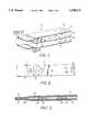
- FIG. 1is a disassembled view of a simplified structure in accordance with the present invention.
- FIG. 2is a top plan view of the structure shown in FIG. 1.
- FIG. 3is a cross sectional view of the structure shown in FIG. 1, taken along section line 3--3 of FIG. 2.
- FIG. 4A and FIG. 4Bare views of a method of attaching a hinge fitting to a graphite/epoxy laminated structure.
- FIG. 5A and FIG. 5Bare views of attaching a hinge fitting to a bonded panel with interleaved titanium sheets.
- FIG. 1illustrates the basic concept of the present invention utilizing a laminated structure which will accommodate a metal fitting (not shown). However, it is to be understood that the laminate would be repeated, in an actual utilization of the invention, so as to provide sufficient bearing strength for an installed fitting.
- Spaced graphite/epoxy plies 12 and 14are of a conventional prepreg nature wherein the graphite fiber is impregnated with epoxy material. Interleaved between the plies 12 and 14 is a thin titanium sheet, typically having a thickness of 0.016 inches.
- the graphite/epoxy plies 12 and 14have aligned holes 16, 18 for accommodating a typical fixture thereon. In order to allow fitting fasteners through all plies, holes 22 are formed in the titanium sheet 20 and are aligned with the holes 16, 18 in the adjacent graphite/epoxy plies.
- a series of perforations or holes 24must be made on an opposite end of the titanium sheet 20. These holes allow the flow of epoxy material therethrough so as to contact confronting surfaces of the graphite/epoxy plies 12 and 14--clearly illustrated in the cross sectional view of FIG. 3.
- the epoxy/plugs 26fill the holes 24 and contact the confronting surfaces of the graphite/epoxy plies 12 and 14.
- the epoxy materialflows between the remaining confronting graphite/epoxy surface areas, as indicated by reference numeral 28, so as to bond these graphite/epoxy plies together in areas away from the interleaved titanium sheet. This will occur in areas outside the immediate installation of a fitting.
- the holes in the titanium sheetallow the footprint of the thin titanium sheet to be over an area sufficient in size to allow for the efficient transfer of load in the titanium to the composite fiber material of the graphite/epoxy plies without causing a weight penalty, i.e., the holes in the titanium reduce the size necessary (effective density) of the titanium sheet.
- the perforation size and quantity of the holesare selected to provide a "fail safe" gripping mechanism between the titanium sheet and the adjacent composite plies in order to allow for the load transfer between the titanium sheet and the composite matrix graphite/epoxy plies in the unlikely event that shear bond between the confronting faces of the titanium sheet and the composite matrix plies is completely disbonded.
- the number of plies in the area of the fittingmay be 27 for an inner skin and 24 for an outer skin.
- this numbermay be drastically reduced.
- the same bearing area for the fastener attaching a fitting to the inner and outer laminates of a bonded panelwill be achieved by including 3 interleaved titanium sheets between 6 plies of graphite--in an inner skin; and a single titanium sheet interleaved between 11 graphite/epoxy plies--in an outer skin.
Landscapes
- Laminated Bodies (AREA)
- Carbon And Carbon Compounds (AREA)
Abstract
Description
Claims (1)
Priority Applications (6)
| Application Number | Priority Date | Filing Date | Title |
|---|---|---|---|
| US08/371,432US5500272A (en) | 1995-01-11 | 1995-01-11 | High efficiency load transfer in composite structure |
| DE0807020TDE807020T1 (en) | 1995-01-11 | 1996-01-11 | HIGHLY EFFICIENT LOAD TRANSFER IN A COMPOSITE |
| JP8521887AJPH11501583A (en) | 1995-01-11 | 1996-01-11 | Highly efficient load transfer in composite structures |
| EP96905390AEP0807020A1 (en) | 1995-01-11 | 1996-01-11 | High efficiency load transfer in composite structure |
| PCT/US1996/001618WO1996021561A1 (en) | 1995-01-11 | 1996-01-11 | High efficiency load transfer in composite structure |
| ES96905390TES2112817T1 (en) | 1995-01-11 | 1996-01-11 | HIGH PERFORMANCE EFFORTS TRANSMITTER IN COMPOSITE STRUCTURES. |
Applications Claiming Priority (1)
| Application Number | Priority Date | Filing Date | Title |
|---|---|---|---|
| US08/371,432US5500272A (en) | 1995-01-11 | 1995-01-11 | High efficiency load transfer in composite structure |
Publications (1)
| Publication Number | Publication Date |
|---|---|
| US5500272Atrue US5500272A (en) | 1996-03-19 |
Family
ID=23463978
Family Applications (1)
| Application Number | Title | Priority Date | Filing Date |
|---|---|---|---|
| US08/371,432Expired - LifetimeUS5500272A (en) | 1995-01-11 | 1995-01-11 | High efficiency load transfer in composite structure |
Country Status (6)
| Country | Link |
|---|---|
| US (1) | US5500272A (en) |
| EP (1) | EP0807020A1 (en) |
| JP (1) | JPH11501583A (en) |
| DE (1) | DE807020T1 (en) |
| ES (1) | ES2112817T1 (en) |
| WO (1) | WO1996021561A1 (en) |
Cited By (16)
| Publication number | Priority date | Publication date | Assignee | Title |
|---|---|---|---|---|
| US6030483A (en)* | 1996-09-10 | 2000-02-29 | Wilson; Graeme Paul | Method of forming laminates using a tessellated core |
| EP1010495A3 (en)* | 1998-12-15 | 2002-01-09 | Diamond Machining Technology Inc. | Support structure for two-sided abrasive tool and the like and method of assembling same |
| US6402603B1 (en) | 1998-12-15 | 2002-06-11 | Diamond Machining Technology, Inc. | Two-sided abrasive tool |
| US20040118531A1 (en)* | 2002-12-19 | 2004-06-24 | Kimberly-Clark Worldwide, Inc. | Tissue products having uniformly deposited hydrophobic additives and controlled wettability |
| US20050053765A1 (en)* | 2003-09-04 | 2005-03-10 | Albers Robert G. | Resin infused transparent skin panel and method of making same |
| US20050051255A1 (en)* | 2003-09-04 | 2005-03-10 | Nordman Paul S. | Window skin panel and method of making same |
| US20060159887A1 (en)* | 2003-07-03 | 2006-07-20 | Rajabali Abdoel F | Laminate with local reinforcement |
| US20080286073A1 (en)* | 2007-05-17 | 2008-11-20 | The Boeing Company | Hybrid contoured load-spreading washer |
| US20090003965A1 (en)* | 2007-05-17 | 2009-01-01 | The Boeing Company | Hybrid Contoured Load-Spreading Washer |
| US20090112540A1 (en)* | 2007-10-25 | 2009-04-30 | Kessel Jamie A | Method and apparatus for composite part data extraction |
| US20110087463A1 (en)* | 2009-10-13 | 2011-04-14 | The Boeing Company | Composite Information Display for a Part |
| US8652606B2 (en) | 2010-08-17 | 2014-02-18 | The Boeing Company | Composite structures having composite-to-metal joints and method for making the same |
| US20140054418A1 (en)* | 2011-02-28 | 2014-02-27 | Airbus Operations Gmbh | Door frame construction, fuselage portion and aircraft or spacecraft |
| US8993084B2 (en) | 2010-08-17 | 2015-03-31 | The Boeing Company | Multi-layer metallic structure and composite-to-metal joint methods |
| US9522512B2 (en) | 2010-08-17 | 2016-12-20 | The Boeing Company | Methods for making composite structures having composite-to-metal joints |
| US10074459B2 (en)* | 2016-09-23 | 2018-09-11 | Yazaki Corporation | Conductive resin body, vehicle earth structure, and method of manufacturing conductive resin body |
Families Citing this family (1)
| Publication number | Priority date | Publication date | Assignee | Title |
|---|---|---|---|---|
| US8333345B2 (en)* | 2010-08-26 | 2012-12-18 | The Boeing Company | Composite aircraft joint |
Citations (2)
| Publication number | Priority date | Publication date | Assignee | Title |
|---|---|---|---|---|
| US3711934A (en)* | 1970-09-17 | 1973-01-23 | Monsanto Co | Method of preparing metal foil/graphite fiber/epoxy resin laminates |
| US4229473A (en)* | 1978-03-24 | 1980-10-21 | The United States Of America As Represented By The Administrator Of The National Aeronautics And Space Administration | Partial interlaminar separation system for composites |
- 1995
- 1995-01-11USUS08/371,432patent/US5500272A/ennot_activeExpired - Lifetime
- 1996
- 1996-01-11JPJP8521887Apatent/JPH11501583A/enactivePending
- 1996-01-11ESES96905390Tpatent/ES2112817T1/enactivePending
- 1996-01-11DEDE0807020Tpatent/DE807020T1/enactivePending
- 1996-01-11WOPCT/US1996/001618patent/WO1996021561A1/ennot_activeApplication Discontinuation
- 1996-01-11EPEP96905390Apatent/EP0807020A1/ennot_activeWithdrawn
Patent Citations (2)
| Publication number | Priority date | Publication date | Assignee | Title |
|---|---|---|---|---|
| US3711934A (en)* | 1970-09-17 | 1973-01-23 | Monsanto Co | Method of preparing metal foil/graphite fiber/epoxy resin laminates |
| US4229473A (en)* | 1978-03-24 | 1980-10-21 | The United States Of America As Represented By The Administrator Of The National Aeronautics And Space Administration | Partial interlaminar separation system for composites |
Cited By (35)
| Publication number | Priority date | Publication date | Assignee | Title |
|---|---|---|---|---|
| US6030483A (en)* | 1996-09-10 | 2000-02-29 | Wilson; Graeme Paul | Method of forming laminates using a tessellated core |
| EP1010495A3 (en)* | 1998-12-15 | 2002-01-09 | Diamond Machining Technology Inc. | Support structure for two-sided abrasive tool and the like and method of assembling same |
| US6402603B1 (en) | 1998-12-15 | 2002-06-11 | Diamond Machining Technology, Inc. | Two-sided abrasive tool |
| US6528141B1 (en) | 1998-12-15 | 2003-03-04 | Diamond Machining Technology, Inc. | Support structure and method of assembling same |
| US20040118531A1 (en)* | 2002-12-19 | 2004-06-24 | Kimberly-Clark Worldwide, Inc. | Tissue products having uniformly deposited hydrophobic additives and controlled wettability |
| US20060159887A1 (en)* | 2003-07-03 | 2006-07-20 | Rajabali Abdoel F | Laminate with local reinforcement |
| US8426007B2 (en)* | 2003-07-03 | 2013-04-23 | Fokker Aerostructures B.V. | Laminate with local reinforcement |
| US7651756B2 (en) | 2003-09-04 | 2010-01-26 | The Boeing Company | Resin infused transparent skin panel and method of making same |
| US20070034743A1 (en)* | 2003-09-04 | 2007-02-15 | The Boeing Company | Composite single pane window for an aircraft and method of making same |
| US7300693B2 (en)* | 2003-09-04 | 2007-11-27 | The Boeing Company | Resin infused transparent skin panel and method of making same |
| US20080078494A1 (en)* | 2003-09-04 | 2008-04-03 | Nordman Paul S | Window skin panel and method of making same |
| US20080131661A1 (en)* | 2003-09-04 | 2008-06-05 | Albers Robert G | Resin infused transparent skin panel and method of making same |
| US20050053765A1 (en)* | 2003-09-04 | 2005-03-10 | Albers Robert G. | Resin infused transparent skin panel and method of making same |
| US8262823B2 (en)* | 2003-09-04 | 2012-09-11 | The Boeing Company | Window skin panel and method of making same |
| US7968170B2 (en) | 2003-09-04 | 2011-06-28 | The Boeing Company | Composite single pane window for an aircraft and method of making same |
| US20050051255A1 (en)* | 2003-09-04 | 2005-03-10 | Nordman Paul S. | Window skin panel and method of making same |
| WO2008144321A3 (en)* | 2007-05-17 | 2009-05-07 | Boeing Co | Hybrid contoured load-spreading washer |
| US8528874B2 (en) | 2007-05-17 | 2013-09-10 | The Boeing Company | Hybrid contoured load-spreading washer |
| US8511034B2 (en) | 2007-05-17 | 2013-08-20 | The Boeing Company | Hybrid contoured load-spreading washer |
| CN101675257B (en)* | 2007-05-17 | 2012-07-04 | 波音公司 | Hybrid Contoured Load Spreading Washers |
| US20090003965A1 (en)* | 2007-05-17 | 2009-01-01 | The Boeing Company | Hybrid Contoured Load-Spreading Washer |
| US20080286073A1 (en)* | 2007-05-17 | 2008-11-20 | The Boeing Company | Hybrid contoured load-spreading washer |
| US20090112540A1 (en)* | 2007-10-25 | 2009-04-30 | Kessel Jamie A | Method and apparatus for composite part data extraction |
| US8442804B2 (en) | 2007-10-25 | 2013-05-14 | The Boeing Company | Method and apparatus for composite part data extraction |
| US20110087463A1 (en)* | 2009-10-13 | 2011-04-14 | The Boeing Company | Composite Information Display for a Part |
| US8620627B2 (en) | 2009-10-13 | 2013-12-31 | The Boeing Company | Composite information display for a part |
| US8652606B2 (en) | 2010-08-17 | 2014-02-18 | The Boeing Company | Composite structures having composite-to-metal joints and method for making the same |
| US8894801B2 (en) | 2010-08-17 | 2014-11-25 | The Boeing Company | Composite structures having composite-to-metal joints and method for making the same |
| US8993084B2 (en) | 2010-08-17 | 2015-03-31 | The Boeing Company | Multi-layer metallic structure and composite-to-metal joint methods |
| US9522512B2 (en) | 2010-08-17 | 2016-12-20 | The Boeing Company | Methods for making composite structures having composite-to-metal joints |
| US9919507B2 (en) | 2010-08-17 | 2018-03-20 | The Boeing Company | Process for inhibiting galvanic corrosion of an aluminum structure connected, without using a splice plate, to a composite structure having a fiber including graphite |
| US10112373B2 (en) | 2010-08-17 | 2018-10-30 | The Boeing Company | Multi-layer metallic structure and composite-to-metal joint methods |
| US11084269B2 (en) | 2010-08-17 | 2021-08-10 | The Boeing Company | Multi-layer metallic structure and composite-to-metal joint methods |
| US20140054418A1 (en)* | 2011-02-28 | 2014-02-27 | Airbus Operations Gmbh | Door frame construction, fuselage portion and aircraft or spacecraft |
| US10074459B2 (en)* | 2016-09-23 | 2018-09-11 | Yazaki Corporation | Conductive resin body, vehicle earth structure, and method of manufacturing conductive resin body |
Also Published As
| Publication number | Publication date |
|---|---|
| WO1996021561A1 (en) | 1996-07-18 |
| JPH11501583A (en) | 1999-02-09 |
| ES2112817T1 (en) | 1998-04-16 |
| DE807020T1 (en) | 1998-05-28 |
| EP0807020A1 (en) | 1997-11-19 |
Similar Documents
| Publication | Publication Date | Title |
|---|---|---|
| US5500272A (en) | High efficiency load transfer in composite structure | |
| US5160771A (en) | Joining metal-polymer-metal laminate sections | |
| US5951800A (en) | Fiber/metal laminate splice | |
| US7197852B2 (en) | Internally stiffened composite panels and methods for their manufacture | |
| US4113910A (en) | Composite load coupler for reinforcing composite structural joints | |
| US4433021A (en) | Sound attenuation sandwich panel including barrier material for corrosion control | |
| US7575194B2 (en) | Apparatuses and methods for joining composite members and other structural members in aircraft wing boxes and other structures | |
| CA1071376A (en) | Reinforced composite structure and method of fabrication thereof | |
| US5848765A (en) | Reduced amplitude corrugated web spar | |
| US9346223B2 (en) | Apparatus for and method of inhibiting delamination | |
| US20070000596A1 (en) | Methods of Forming Metal Foil Ply Replacement in Composite Structures | |
| JPH0335105B2 (en) | ||
| EP2621802B1 (en) | Stiffener run-out | |
| US5567535A (en) | Fiber/metal laminate splice | |
| JPS63317322A (en) | Two-stage composite material joint | |
| WO2022057115A1 (en) | Airplane wing fuel tank access cover and structure of peripheral area of access cover | |
| DE102008047333B4 (en) | Compounds between a monolithic metal component and an endless fiber-reinforced laminate component and method for producing the same | |
| EP1573141B1 (en) | Large composite structures and a process for fabricating large composite structures | |
| CN212313890U (en) | Structure of fuel tank opening cover and peripheral area of opening cover of airplane wing | |
| WO2005049933A1 (en) | Sandwich panel and a method of producing a sandwich panel | |
| EP1641611B1 (en) | Laminate with fill layer | |
| US20200370578A1 (en) | Shear pin for panel structural support | |
| GB1342898A (en) | Composite panels | |
| CA2405410A1 (en) | Multi-dimensional tailored laminate | |
| JPH0455859B2 (en) |
Legal Events
| Date | Code | Title | Description |
|---|---|---|---|
| AS | Assignment | Owner name:GRUMMAN AEROSPACE CORPORATION, NEW YORK Free format text:ASSIGNMENT OF ASSIGNORS INTEREST;ASSIGNOR:PADDEN, VINCENT T.;REEL/FRAME:007311/0569 Effective date:19941202 | |
| STCF | Information on status: patent grant | Free format text:PATENTED CASE | |
| FPAY | Fee payment | Year of fee payment:4 | |
| AS | Assignment | Owner name:LEHMAN COMMERICIAL PAPER INC., NEW YORK Free format text:PLEDGE & SECURITY AGMT;ASSIGNORS:VOUGHT AIRCRAFT INDUSTRIES, INC.;VAC HOLDINGS II, INC.;NORTHROP GRUMMAN COMMERCIAL AIRCRAFT COMPANY;AND OTHERS;REEL/FRAME:011084/0383 Effective date:20000724 | |
| AS | Assignment | Owner name:VOUGHT AIRCRAFT INDUSTRIES, INC., TEXAS Free format text:ASSIGNMENT OF ASSIGNORS INTEREST;ASSIGNOR:NORTHROP GRUMMAN CORPORATION;REEL/FRAME:011333/0912 Effective date:20000717 | |
| FPAY | Fee payment | Year of fee payment:8 | |
| AS | Assignment | Owner name:LEHMAN COMMERCIAL PAPER INC., NEW YORK Free format text:SECURITY AGREEMENT;ASSIGNOR:VOUGHT AIRCRAFT INDUSTRIES, INC.;REEL/FRAME:015509/0322 Effective date:20041222 | |
| FPAY | Fee payment | Year of fee payment:12 | |
| AS | Assignment | Owner name:BARCLAYS BANK PLC, NEW YORK Free format text:TRANSFER OF SECURITY INTEREST;ASSIGNOR:LEHMAN COMMERCIAL PAPER, INC.;REEL/FRAME:023129/0496 Effective date:20090730 | |
| AS | Assignment | Owner name:VOUGHT AIRCRAFT INDUSTRIES, INC.,TEXAS Free format text:RELEASE BY SECURED PARTY;ASSIGNOR:BARCLAYS BANK PLC;REEL/FRAME:024547/0204 Effective date:20100616 | |
| AS | Assignment | Owner name:PNC BANK, NATIONAL ASSOCIATION, PENNSYLVANIA Free format text:SECURITY AGREEMENT;ASSIGNOR:TRIUMPH AEROSTRUCTURES, LLC;REEL/FRAME:024630/0444 Effective date:20100616 | |
| AS | Assignment | Owner name:ROYAL BANK OF CANADA, AS ADMINISTRATIVE AGENT, CAN Free format text:SECURITY AGREEMENT;ASSIGNOR:TRIUMPH AEROSTRUCTURES, LLC;REEL/FRAME:024733/0151 Effective date:20100616 | |
| AS | Assignment | Owner name:TRIUMPH AEROSTRUCTURES, LLC, TEXAS Free format text:RELEASE BY SECURED PARTY;ASSIGNOR:ROYAL BANK OF CANADA;REEL/FRAME:050462/0287 Effective date:20110404 | |
| AS | Assignment | Owner name:TRIUMPH AEROSTRUCTURES, LLC, TEXAS Free format text:RELEASE BY SECURED PARTY;ASSIGNOR:PNC BANK, NATIONAL ASSOCIATION;REEL/FRAME:053516/0200 Effective date:20200817 Owner name:TRIUMPH ACTUATION SYSTEMS - CONNECTICUT, LLC, PENNSYLVANIA Free format text:RELEASE BY SECURED PARTY;ASSIGNOR:PNC BANK, NATIONAL ASSOCIATION;REEL/FRAME:053516/0200 Effective date:20200817 Owner name:TRIUMPH ACTUATION SYSTEMS, LLC, PENNSYLVANIA Free format text:RELEASE BY SECURED PARTY;ASSIGNOR:PNC BANK, NATIONAL ASSOCIATION;REEL/FRAME:053516/0200 Effective date:20200817 Owner name:TRIUMPH ACTUATION SYSTEMS - YAKIMA, LLC, WASHINGTON Free format text:RELEASE BY SECURED PARTY;ASSIGNOR:PNC BANK, NATIONAL ASSOCIATION;REEL/FRAME:053516/0200 Effective date:20200817 Owner name:TRIUMPH ENGINEERED SOLUTIONS, INC., ARIZONA Free format text:RELEASE BY SECURED PARTY;ASSIGNOR:PNC BANK, NATIONAL ASSOCIATION;REEL/FRAME:053516/0200 Effective date:20200817 Owner name:TRIUMPH BRANDS, INC., PENNSYLVANIA Free format text:RELEASE BY SECURED PARTY;ASSIGNOR:PNC BANK, NATIONAL ASSOCIATION;REEL/FRAME:053516/0200 Effective date:20200817 Owner name:TRIUMPH GROUP, INC., PENNSYLVANIA Free format text:RELEASE BY SECURED PARTY;ASSIGNOR:PNC BANK, NATIONAL ASSOCIATION;REEL/FRAME:053516/0200 Effective date:20200817 Owner name:TRIUMPH ENGINE CONTROL SYSTEMS, LLC, PENNSYLVANIA Free format text:RELEASE BY SECURED PARTY;ASSIGNOR:PNC BANK, NATIONAL ASSOCIATION;REEL/FRAME:053516/0200 Effective date:20200817 Owner name:TRIUMPH THERMAL SYSTEMS - MARYLAND, INC., PENNSYLVANIA Free format text:RELEASE BY SECURED PARTY;ASSIGNOR:PNC BANK, NATIONAL ASSOCIATION;REEL/FRAME:053516/0200 Effective date:20200817 Owner name:TRIUMPH GEAR SYSTEMS, INC., UTAH Free format text:RELEASE BY SECURED PARTY;ASSIGNOR:PNC BANK, NATIONAL ASSOCIATION;REEL/FRAME:053516/0200 Effective date:20200817 Owner name:TRIUMPH INSULATION SYSTEMS, LLC, CALIFORNIA Free format text:RELEASE BY SECURED PARTY;ASSIGNOR:PNC BANK, NATIONAL ASSOCIATION;REEL/FRAME:053516/0200 Effective date:20200817 Owner name:TRIUMPH CONTROLS, LLC, PENNSYLVANIA Free format text:RELEASE BY SECURED PARTY;ASSIGNOR:PNC BANK, NATIONAL ASSOCIATION;REEL/FRAME:053516/0200 Effective date:20200817 Owner name:TRIUMPH INTEGRATED AIRCRAFT INTERIORS, INC., PENNSYLVANIA Free format text:RELEASE BY SECURED PARTY;ASSIGNOR:PNC BANK, NATIONAL ASSOCIATION;REEL/FRAME:053516/0200 Effective date:20200817 |