US5499984A - Universal modular reamer system - Google Patents
Universal modular reamer systemDownload PDFInfo
- Publication number
- US5499984A US5499984AUS08/224,046US22404694AUS5499984AUS 5499984 AUS5499984 AUS 5499984AUS 22404694 AUS22404694 AUS 22404694AUS 5499984 AUS5499984 AUS 5499984A
- Authority
- US
- United States
- Prior art keywords
- head
- shaft
- support
- latch
- cutting head
- Prior art date
- Legal status (The legal status is an assumption and is not a legal conclusion. Google has not performed a legal analysis and makes no representation as to the accuracy of the status listed.)
- Expired - Fee Related
Links
Images
Classifications
- A—HUMAN NECESSITIES
- A61—MEDICAL OR VETERINARY SCIENCE; HYGIENE
- A61B—DIAGNOSIS; SURGERY; IDENTIFICATION
- A61B17/00—Surgical instruments, devices or methods
- A61B17/16—Instruments for performing osteoclasis; Drills or chisels for bones; Trepans
- A61B17/164—Instruments for performing osteoclasis; Drills or chisels for bones; Trepans intramedullary
- A—HUMAN NECESSITIES
- A61—MEDICAL OR VETERINARY SCIENCE; HYGIENE
- A61B—DIAGNOSIS; SURGERY; IDENTIFICATION
- A61B17/00—Surgical instruments, devices or methods
- A61B17/16—Instruments for performing osteoclasis; Drills or chisels for bones; Trepans
- A61B17/1613—Component parts
- A61B17/1615—Drill bits, i.e. rotating tools extending from a handpiece to contact the worked material
- A61B17/1617—Drill bits, i.e. rotating tools extending from a handpiece to contact the worked material with mobile or detachable parts
- A—HUMAN NECESSITIES
- A61—MEDICAL OR VETERINARY SCIENCE; HYGIENE
- A61B—DIAGNOSIS; SURGERY; IDENTIFICATION
- A61B17/00—Surgical instruments, devices or methods
- A61B2017/00477—Coupling
- Y—GENERAL TAGGING OF NEW TECHNOLOGICAL DEVELOPMENTS; GENERAL TAGGING OF CROSS-SECTIONAL TECHNOLOGIES SPANNING OVER SEVERAL SECTIONS OF THE IPC; TECHNICAL SUBJECTS COVERED BY FORMER USPC CROSS-REFERENCE ART COLLECTIONS [XRACs] AND DIGESTS
- Y10—TECHNICAL SUBJECTS COVERED BY FORMER USPC
- Y10S—TECHNICAL SUBJECTS COVERED BY FORMER USPC CROSS-REFERENCE ART COLLECTIONS [XRACs] AND DIGESTS
- Y10S408/00—Cutting by use of rotating axially moving tool
- Y10S408/713—Tool having detachable cutting edge
Definitions
- the inventionrelates to medullary reaming systems and to flexible drive shafts therefor.
- Medullary reamersare used to enlarge the medullary canals of bone for various reasons.
- the medullary canals of bonetypically have some degree of curvature and, for this reason, are almost always prepared with reamers having a flexible shaft.
- One type of prior flexible medullary reamer shaftconsists of a spiral or helically wound metal wire or strip which comprises the shaft of the reamer.
- a disadvantage of this type of shaftis that the reamer can be operated only in the forward mode of rotation. If the reamer is reversed, which is occasionally necessary in order to free a lodged reamer, for example, the shaft unwinds, damaging the shaft.
- Another disadvantage of this spiral shaft designis that the voids between the shaft coils can trap blood and tissue, making it extremely difficult to thoroughly and properly clean and sterilize the shaft after use.
- Another disadvantageis that if the cutting head experiences unusually high resistance, the driving torque will accumulate in the shaft as its coils close and then, when it overcomes the resistance to the head, will be released in a sudden burst, causing the cutting head to jump or spin ahead rapidly in an uncontrolled fashion. Such irregular movement of the cutting head may damage the bone.
- medullary reamer shaftcomprises a plurality of parallel, flexible elements joined together at their opposite ends by means of a welded or soldered connection.
- Such a shaft constructionsuffers from most of the same disadvantages as the helically coiled shaft described above.
- Another disadvantageoccurs in attempting to utilize the central bore of the reamer, to receive a long, small diameter guide wire, which had previously been inserted into the medullary canal to act as a track for the advancing reamer. Except at its respective ends, this parallel-element reamer shaft lacks a well-defined and bordered central bore, making it difficult to prevent the guide wire from exiting the reamer in the area of the free standing shaft wires during the initial positioning of the guide wire within the reamer.
- a hollow tubular shaftformed of synthetic plastic material or a fiber-reinforced composite material.
- plastic shaftsmay lack the necessary torsional strength.
- the reameris autoclaved often and plastic will ultimately fail.
- a disadvantage of fiber-reinforced composite shaftsis that, on failure, there is a danger that fibers will enter the blood stream.
- the cutting headhas been fixed to the flexible shaft, permanently by suitable bonding or the like.
- the head and the shaftform an integral unit and, when it is desired to use a different size cutting head, an entire reaming unit must be substituted.
- suitable fastenerssuch as a set screw, but this requires handling and the use of suitable tools.
- An important feature of the inventionis the provision of a medullary reamer with a flexible drive shaft which provides uniform transmission of energy to a cutting head in forward and reverse directions and which is easy to clean.
- a further feature of the inventionis the provision of a reamer shaft of the type set forth which minimizes the risk of body contamination.
- Another feature of the inventionis the provision of a reaming system which permits quick and easy mounting of any of a plurality of different cutting heads on a shaft without the use of tools and without manual handling of the cutting head
- a further feature of the inventionis the provision of a reaming system of the type set forth which affords automatic releasable latching of a cutting head to the shaft.
- a medullary rotational reamerhaving a flexible shaft with a cutting head at one end and an adaptor piece at its opposite end for connecting the shaft to a rotational drive element thereby causing rotation of the shaft, the improvement comprising: the flexible shaft being comprised of a metal alloy including titanium.
- a modular medullary rotational reaming systemcomprising: a flexible shaft having a drive coupling portion at one end thereof for connecting the shaft to a rotational drive element to cause rotation of the shaft and, a first head coupling portion at the other end thereof, first latch structure on the first head coupling portion movable between latching and unlatching conditions, a cutting head having a second head coupling portion thereon including second latch structure, and a support for storing the cutting head in a supported position readily accessible to a user, the first and second head coupling portions being mateably engageable with each other in a coupled condition for interconnecting the head and the shaft, the support being engageable with the first latch structure for holding it in its unlatching condition when the first and second head coupling portions are engaged in their coupled condition while the cutting head is held on the support, the first latch structure being responsive to removal of the cutting head from the support while the first and second head coupling portions are engaged in their coupled condition for moving to the latching condition,
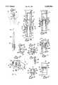
- FIG. 1is a fragmentary, side elevational view of the reamer of a medullary reaming system in accordance with the present invention, with portions broken away and showing different positions in phantom to illustrate the flexibility of the shaft;
- FIG. 2is a fragmentary, perspective view of the support of the reaming system holding a plurality of cutting heads and illustrating insertion of the reamer shaft;
- FIG. 3is an enlarged, fragmentary view in partial vertical section showing the female connector of a cutting head held on the support with the male connector on the shaft about to be inserted;
- FIG. 4is an end view of the female connector taken along the line 4--4 in FIG. 3;
- FIG. 5is an end view of the male connector taken along the line 5--5 in FIG. 3;
- FIG. 6is a view similar to FIG. 3, illustrating the male and female connectors in their coupled condition
- FIG. 7is a view similar to FIG. 6, illustrating the latching engagement of the male and female connectors after removal from the support;
- FIG. 8is a fragmentary, side elevational view taken along the line 8--8 in FIG. 7;
- FIG. 9is a sectional view taken along the line 9--9 in FIG. 7;
- FIG. 10is a fragmentary perspective view of a reamer with a fixed cutting head.
- the system 10includes a reamer 11, comprising a cutting head 20 fixed to the end of a flexible shaft 30, and a support 12 adapted for holding a plurality of heads 20 in a support position for ready access by a user.
- the support 12includes a bracket 13 which may be in the form of a flat plate having a plurality of support notches 15 formed therein.
- Each of the notches 15has a part-circular inner end and a pair of parallel notch edges 16 and 17 which have outwardly tapered portions 18 at their outer ends.
- Each of the cutting heads 20has a head body 21, which is a toothed or fluted cutting element having an axial bore 21a therethrough. Integral with the head body 21 at its tail end is a coupling portion in the nature of a female connector 22, which is preferably in the form of a cylindrical tubular coupling shank 23. Referring also to FIGS. 3, 4 and 7, the coupling shank 23 has an axial bore 24 therethrough with an enlarged-diameter counterbore 24a at its distal end, the counterbore 24a being provided with parallel flats 24b along diametrically opposite sides thereof.
- lateral slots or grooves 25 and 26are formed as chords of the coupling shank 23 and are sufficiently deep to communicate with the counterbore 24a adjacent to its inner end for respectively defining radial apertures 27 and 28 (FIG. 7).
- the flexible shaft 30is in the nature of a cylindrical tubular member having a cylindrical outer surface 31 and an axial bore 32 therethrough.
- the shaft 30may have any desired length, depending upon the particular application, but may typically be in the range of from 12 to 20 inches. It is a significant aspect of the invention that the shaft 30 is formed of a titanium alloy and, more specifically, of a nickel-titanium alloy of a type which has considerable flexibility.
- the nickel-titanium alloyis "super elastic" alloy having a maximum recoverable strain of approximately 8%, i.e., the material can be strained up to 8% and will still elastically return to its original configuration.
- the flexible shaft 30which has great torsional strength and yet provides the flexibility necessary for medullary reaming operations.
- the monolithic metal structureprecludes any release of fibrous material or the like in the event of failure of the shaft.
- the flexible shaft 30is formed of a nickel-titanium alloy of the type sold by Raychem under the designation TINEL® Alloy BB.
- the flexible shaft 30is coupled at one end thereof by a drive coupler or adaptor 33 to an associated source of rotational drive power (not shown) for rotating the shaft about its axis, all in a known manner.
- a coupling structureIntegral with the shaft 30 at its other end and projecting axially therefrom is a coupling structure in the nature of a male connector 35 of reduced cross-sectional area, so that the connector 35 cooperates with the adjacent end of the shaft 30 to define therebetween an annular shoulder 35a.
- the male connector 35is basically cylindrical in shape and has a pair of parallel slots 34 extending thereacross at the distal end thereof as chords thereof, thereby to form two diametrically flexible arms 36 and 37, respectively having flattened outer surfaces 36a and 37a along most of their length.
- the flattened surfaces 36a and 37aterminate short of the distal ends of the arms 36 and 37 so as to define laterally outwardly projecting latch fingers or tabs 38 or 39, respectively, on the arms 36 and 37.
- a plurality of the cutting heads 20are preferably supported on the support 12, as illustrated in FIG. 2.
- the cutting heads 20all have identical coupling shanks 23, but may have different size head bodies 21.
- the coupling shanks 23are respectively received in the support notches 15.
- the notch edges 16 and 17are spaced apart a distance less than the outer diameter of the coupling shank 23 and are respectively received in the lateral slots or grooves 25 and 26 of the coupling shank 23, as is best illustrated in FIGS. 2, 3 and 6.
- the distance between the notch edges 16 and 17is such that, in this supported position, they will respectively extend radially inwardly of the coupling shank 23 at least as far as the flats 24b.
- the male connector 35When a user wishes to attach a particular cutting head 20 to the flexible shaft 30, the male connector 35 is aligned beneath the selected cutting head 20, as illustrated in FIGS. 2 and 3, and is rotationally oriented so that the flexible arms 36 and 37 are, respectively, aligned beneath the flats 24b of the coupling shank 23. The male connector 35 is then inserted into the female connector 22 in the direction of the arrow in FIG. 2 to the coupled condition illustrated in FIG. 6, wherein the distal end of the coupling shank 23 bottoms against the shoulder 35a on the shaft 30.
- the arms 36 and 37will flex to permit their insertion into the counterbore 24a of the coupling shank 23 and, as was indicated above, the support bracket 13 will firmly hold the cutting head 20 against axial movement in response to this insertion.
- the latch fingers or tabs 38 and 39will be respectively disposed opposite the lateral slots or grooves 25 and 26 in the coupling shank 23, but will be deflected out of those slots or grooves to an unlatching condition shown in FIG. 6, wherein they are prevented from engagement in the slots 25 and 26 by the notch edges 16 and 17 of the support bracket 13.
- the axial bore 32 through the flexible shaft 30continues through the male connector 35, and the axial bore 24 through the coupling shank 23 is continuous with the axial bore 21a through the cutting head body 21.
- the cutting head 20is mounted on the flexible shaft 30, as is illustrated in FIG. 1, there is a continuous axial bore through the entire assembly, in standard fashion, for accommodating a guide wire 40.
- the guide wire 40having an enlarged knob 41 at its distal end sized so as not to pass through the axial bore in the reamer 11, for purposes of retrieving the reamer, all in a known manner.
- FIG. 10there is shown a flexible shaft 50, which may be the same as the shaft 30 except that it lacks the male connector 35, to which a cutting head 60 is fixedly Secured by any suitable means.
- an improved reaming systemwhich has a reamer with a flexible shaft of great torsional strength while minimizing the chance of contamination and, at the same time, is modular so as to provide a simple and effective means for removably connecting the reamer shaft to a selected one of a plurality of different cutting heads without the use of tools.
Landscapes
- Health & Medical Sciences (AREA)
- Surgery (AREA)
- Life Sciences & Earth Sciences (AREA)
- Biomedical Technology (AREA)
- Medical Informatics (AREA)
- Orthopedic Medicine & Surgery (AREA)
- Oral & Maxillofacial Surgery (AREA)
- Engineering & Computer Science (AREA)
- Dentistry (AREA)
- Heart & Thoracic Surgery (AREA)
- Nuclear Medicine, Radiotherapy & Molecular Imaging (AREA)
- Molecular Biology (AREA)
- Animal Behavior & Ethology (AREA)
- General Health & Medical Sciences (AREA)
- Public Health (AREA)
- Veterinary Medicine (AREA)
- Prostheses (AREA)
Abstract
Description
Claims (7)
Priority Applications (2)
| Application Number | Priority Date | Filing Date | Title |
|---|---|---|---|
| US08/224,046US5499984A (en) | 1994-04-07 | 1994-04-07 | Universal modular reamer system |
| CA002143709ACA2143709A1 (en) | 1994-04-07 | 1995-03-01 | Universal modular reamer system |
Applications Claiming Priority (1)
| Application Number | Priority Date | Filing Date | Title |
|---|---|---|---|
| US08/224,046US5499984A (en) | 1994-04-07 | 1994-04-07 | Universal modular reamer system |
Publications (1)
| Publication Number | Publication Date |
|---|---|
| US5499984Atrue US5499984A (en) | 1996-03-19 |
Family
ID=22839082
Family Applications (1)
| Application Number | Title | Priority Date | Filing Date |
|---|---|---|---|
| US08/224,046Expired - Fee RelatedUS5499984A (en) | 1994-04-07 | 1994-04-07 | Universal modular reamer system |
Country Status (2)
| Country | Link |
|---|---|
| US (1) | US5499984A (en) |
| CA (1) | CA2143709A1 (en) |
Cited By (71)
| Publication number | Priority date | Publication date | Assignee | Title |
|---|---|---|---|---|
| US5690636A (en)* | 1995-12-21 | 1997-11-25 | Johnson & Johnson Professional, Inc. | Punch system for tibial prosthesis |
| US5693047A (en)* | 1996-02-08 | 1997-12-02 | Zimmer, Inc. | Press fit intramedullary reamer head |
| US5733290A (en)* | 1995-12-21 | 1998-03-31 | Johnson & Johnson Professional, Inc. | Quick-release tibial alignment handle |
| US5788701A (en)* | 1995-12-21 | 1998-08-04 | Johnson & Johnson Professional, Inc. | Instrument system for knee prothesis implantation with universal handle or slap hammer |
| US5976143A (en)* | 1997-12-23 | 1999-11-02 | Johnson & Johnson Professional, Inc. | Orthopedic reaming instrument |
| US6149654A (en)* | 1998-05-21 | 2000-11-21 | Johnson; Lanny L. | Intra-articular drill |
| US6174311B1 (en) | 1998-10-28 | 2001-01-16 | Sdgi Holdings, Inc. | Interbody fusion grafts and instrumentation |
| US6273892B1 (en) | 1998-09-10 | 2001-08-14 | Hand Innovations, Inc. | Fracture fixation system |
| US20020045944A1 (en)* | 2000-09-08 | 2002-04-18 | Muhanna Nabil L. | System and methods for inserting a vertebral spacer |
| US6435059B1 (en) | 1999-08-13 | 2002-08-20 | Mark R. Martinez | Light-weight striking tool |
| US20020128658A1 (en)* | 1999-05-14 | 2002-09-12 | White Patrick M. | Tool bit drive shaft connection and method |
| US20030023306A1 (en)* | 2000-03-14 | 2003-01-30 | Mingyan Liu | Vertebral implant for promoting arthrodesis of the spine |
| US20030040798A1 (en)* | 1995-06-07 | 2003-02-27 | Michelson Gary Karlin | Lordotic interbody spinal fusion implants |
| US6536308B1 (en)* | 1999-12-30 | 2003-03-25 | Sturm, Ruger & Company, In. | Tool having an attached working surface |
| WO2003039378A1 (en)* | 2001-11-05 | 2003-05-15 | Precimed S.A. | Drive shaft coupling and flexible surgical reamer |
| WO2003039380A1 (en)* | 2001-11-05 | 2003-05-15 | Precimed S.A. | Torque-transmitting coupling and surgical device |
| US6610089B1 (en) | 1997-08-26 | 2003-08-26 | Sdgi Holdings, Inc. | Spinal implant and cutting tool preparation accessory for mounting the implant |
| US20030176868A1 (en)* | 2002-02-22 | 2003-09-18 | Pepper John R. | Long bone reaming apparatus and method |
| US20040024404A1 (en)* | 2000-09-27 | 2004-02-05 | Peter Steiger | Device for connecting surgical clearing or drilling tool components |
| US6702822B1 (en)* | 1996-01-04 | 2004-03-09 | Joint Medical Products Corporation | Method and apparatus for fitting a prosthesis to a bone |
| US20040073309A1 (en)* | 1997-06-03 | 2004-04-15 | Bianchi John R. | Open intervertebral spacer |
| US20040122432A1 (en)* | 2002-12-02 | 2004-06-24 | Chappuis James L. | Flexible tap apparatus and method of use |
| US6783533B2 (en) | 2001-11-21 | 2004-08-31 | Sythes Ag Chur | Attachable/detachable reaming head for surgical reamer |
| US6805697B1 (en)* | 1999-05-07 | 2004-10-19 | University Of Virginia Patent Foundation | Method and system for fusing a spinal region |
| US20060015110A1 (en)* | 2004-07-15 | 2006-01-19 | Pepper John R | Cutting device |
| US20060095043A1 (en)* | 2004-10-19 | 2006-05-04 | Martz Erik O | Adjustable instrumentation for spinal implant insertion |
| US7150680B2 (en) | 1999-05-14 | 2006-12-19 | Precimed S.A. | Drive shaft coupling |
| US20070050028A1 (en)* | 2005-08-26 | 2007-03-01 | Conner E S | Spinal implants and methods of providing dynamic stability to the spine |
| US20070053754A1 (en)* | 2005-09-08 | 2007-03-08 | Clinton Hartranft | Universal quick flex and method of use |
| US20070244562A1 (en)* | 2005-08-26 | 2007-10-18 | Magellan Spine Technologies, Inc. | Spinal implants and methods of providing dynamic stability to the spine |
| US20070293949A1 (en)* | 2004-10-08 | 2007-12-20 | Salerni Anthony A | Interior connecting interbody cage insertional tools, methods and devices |
| US20080161813A1 (en)* | 2006-12-30 | 2008-07-03 | Precimed S.A. | Cut-off acetabular reamer |
| US20080223225A1 (en)* | 2007-03-13 | 2008-09-18 | Vita-Mix Corporation | Spoon food mixer |
| US20080234664A1 (en)* | 2007-03-19 | 2008-09-25 | Zimmer Technology, Inc. | Handpiece calibration device |
| US20090138015A1 (en)* | 2007-11-19 | 2009-05-28 | Magellan Spine Technologies, Inc. | Spinal implants and methods |
| USD595850S1 (en)* | 2007-02-09 | 2009-07-07 | Gebr. Brasseler Gmbh & Co. Kg | Dental instrument |
| US20090198239A1 (en)* | 2008-02-01 | 2009-08-06 | White William L | Apparatus and procedure for anterior cervical microdiskectomy |
| US20090208902A1 (en)* | 2008-02-20 | 2009-08-20 | Gebr. Brasseler Gmbh & Co. Kg | Dental drill made of plastics |
| US20110051429A1 (en)* | 2009-08-27 | 2011-03-03 | Hong Fu Jin Precision Industry (Shenzhen) Co., Ltd. | Table lamp and rotary joint thereof |
| USD641472S1 (en)* | 2009-02-04 | 2011-07-12 | Shofu Inc. | Dental rotary instrument |
| USD644737S1 (en)* | 2008-09-05 | 2011-09-06 | Shofu Inc. | Dental instrument |
| US20120109229A1 (en)* | 2009-07-10 | 2012-05-03 | Milux Holdind Sa | Hip joint instrument and method |
| USD685090S1 (en) | 2011-10-19 | 2013-06-25 | Grace Manufacturing, Inc. | Surgical reamer |
| USD685473S1 (en) | 2011-10-12 | 2013-07-02 | Grace Manufacturing, Inc. | Surgical reamer |
| US8628575B2 (en) | 2000-08-29 | 2014-01-14 | Nabil L. Muhanna | Vertebral body replacement and method of use |
| US8641717B2 (en) | 2010-07-01 | 2014-02-04 | DePuy Synthes Products, LLC | Guidewire insertion methods and devices |
| US20140081271A1 (en)* | 2012-09-20 | 2014-03-20 | Depuy Mitek, Llc | Low profile reamers and methods of use |
| US20140236156A1 (en)* | 2011-09-16 | 2014-08-21 | CHIRMAT Sàrl | Surgical tool for reaming the diaphyseal canal of long bones |
| US20140257300A1 (en)* | 2013-03-05 | 2014-09-11 | Charles D. Christie | Polymer 4-in-2 femoral cutting instrument having separable a/p and chamfer cutting blocks |
| US20150196306A1 (en)* | 2009-05-08 | 2015-07-16 | DePuy Synthes Products, LLC | Surgical drill with curved burr attachment and method |
| WO2015121869A1 (en)* | 2014-02-17 | 2015-08-20 | T.A.G. Medical Devices - Agriculture Cooperative Ltd. | Flexible bone tool |
| EP2959851A1 (en) | 2014-06-27 | 2015-12-30 | Technosprings Italia S.r.l. | Flexible intramedullary reamer |
| US20160199145A1 (en)* | 2015-01-09 | 2016-07-14 | Biomet Manufacturing, Llc | Method and apparatus for measurement of intramedullary length with radiopaque markings |
| US9588478B1 (en) | 2016-09-30 | 2017-03-07 | Roy Fan | Drive coupling and transmitting assembly for photosensitive drum and toner cartridges |
| US20170265874A1 (en)* | 2016-03-21 | 2017-09-21 | Jug Hee Hwang | Detachable medical cutting tool |
| US9907559B2 (en) | 2009-05-08 | 2018-03-06 | DePuy Synthes Products, Inc. | Disposable burr attachment |
| EP2869789B1 (en)* | 2013-03-14 | 2018-07-25 | Wright Medical Technology, Inc. | Intramedullary ankle system |
| US20180354040A1 (en)* | 2017-06-13 | 2018-12-13 | NN, Inc. | Adaptor with quick release mechanism |
| US10159495B1 (en) | 2017-08-21 | 2018-12-25 | Stryker Corporation | Drill bit for a handheld surgical instrument |
| US20190099257A1 (en)* | 2006-08-16 | 2019-04-04 | Smith & Nephew, Inc. | Helicoil interference fixation system for attaching a graft ligament to a bone |
| US10524805B2 (en) | 2016-01-17 | 2020-01-07 | T.A.G. Medical Devices—Agriculture Cooperative Ltd. | Flexible bone tool |
| US10588642B2 (en)* | 2014-05-15 | 2020-03-17 | Gauthier Biomedical, Inc. | Molding process and products formed thereby |
| US10918427B2 (en) | 2015-01-09 | 2021-02-16 | Biomet Manufacturing, Llc | Anatomic distal fibula plate with anterolateral directed syndesmosis screw holes |
| US11317927B2 (en) | 2017-08-17 | 2022-05-03 | Stryker Corporation | Measurement module for measuring depth of bore holes and related accessories |
| USD954950S1 (en) | 2020-11-18 | 2022-06-14 | Stryker Corporation | Measurement head for a surgical tool |
| US11517328B2 (en) | 2019-03-19 | 2022-12-06 | Arthrex, Inc. | Force absorption system for disposable shavers and burrs |
| USD981561S1 (en) | 2018-12-21 | 2023-03-21 | Stryker Corporation | Self-aligning surgical drill bit |
| US11896239B2 (en) | 2017-08-17 | 2024-02-13 | Stryker Corporation | Surgical handpiece system for depth measurement and related accessories |
| US12076025B2 (en) | 2022-05-11 | 2024-09-03 | DePuy Synthes Products, Inc. | Polymer cutting block |
| US12133654B2 (en) | 2019-05-15 | 2024-11-05 | Stryker Corporation | Powered surgical drill having rotating field bit identification |
| US12232744B2 (en) | 2019-07-15 | 2025-02-25 | Stryker Corporation | Robotic hand-held surgical instrument systems and methods |
Citations (18)
| Publication number | Priority date | Publication date | Assignee | Title |
|---|---|---|---|---|
| US2747384A (en)* | 1954-05-06 | 1956-05-29 | Arthur P Beam | Flexible extension attachment for electric drills |
| US2929510A (en)* | 1955-03-02 | 1960-03-22 | Wil Pen Company | Hypodermic needle holder |
| US3367326A (en)* | 1965-06-15 | 1968-02-06 | Calvin H. Frazier | Intra spinal fixation rod |
| US3554192A (en)* | 1967-07-24 | 1971-01-12 | Orthopedic Equipment Co | Medullary space drill |
| DE2542056A1 (en)* | 1975-09-20 | 1977-03-31 | Hans Dr Reimer | Tool for roughening bone channel for stem of endoprosthesis - is tapping twist drill with wide chip flutes |
| FR2366826A1 (en)* | 1976-05-20 | 1978-05-05 | Howmedica | Surgical brush for use in spinal column - comprises plastics tube and bristles with opening for flushing liquid at handle end |
| US4131116A (en)* | 1977-05-02 | 1978-12-26 | Pevrick Engineering Company, Inc. | Rotary bone cutter for shaping sockets |
| US4304523A (en)* | 1980-06-23 | 1981-12-08 | General Electric Company | Means and method for securing a member to a structure |
| US4541423A (en)* | 1983-01-17 | 1985-09-17 | Barber Forest C | Drilling a curved hole |
| US4706659A (en)* | 1984-12-05 | 1987-11-17 | Regents Of The University Of Michigan | Flexible connecting shaft for intramedullary reamer |
| US4751922A (en)* | 1986-06-27 | 1988-06-21 | Dipietropolo Al | Flexible medullary reamer |
| US4781181A (en)* | 1985-08-27 | 1988-11-01 | Zimmer, S.A. | Boring sensor for intramedullary nail and corresponding intramedullary nail |
| US4813808A (en)* | 1983-08-19 | 1989-03-21 | Gkn Automotive Components Inc. | Axial retaining member and method for interconnecting male and female splined members |
| US4880122A (en)* | 1988-09-23 | 1989-11-14 | Martindell J Richard | Storage and display apparatus for power bits |
| US5108405A (en)* | 1990-08-10 | 1992-04-28 | Mikhail Michael W E | System for performing hip prosethesis revision surgery |
| US5230348A (en)* | 1990-10-12 | 1993-07-27 | Nippon Seisen Co., Ltd. | Guide wire for a catheter |
| US5269785A (en)* | 1990-06-28 | 1993-12-14 | Bonutti Peter M | Apparatus and method for tissue removal |
| US5330480A (en)* | 1993-03-03 | 1994-07-19 | Codman & Shurtleff, Inc. | Surgical drill |
- 1994
- 1994-04-07USUS08/224,046patent/US5499984A/ennot_activeExpired - Fee Related
- 1995
- 1995-03-01CACA002143709Apatent/CA2143709A1/ennot_activeAbandoned
Patent Citations (18)
| Publication number | Priority date | Publication date | Assignee | Title |
|---|---|---|---|---|
| US2747384A (en)* | 1954-05-06 | 1956-05-29 | Arthur P Beam | Flexible extension attachment for electric drills |
| US2929510A (en)* | 1955-03-02 | 1960-03-22 | Wil Pen Company | Hypodermic needle holder |
| US3367326A (en)* | 1965-06-15 | 1968-02-06 | Calvin H. Frazier | Intra spinal fixation rod |
| US3554192A (en)* | 1967-07-24 | 1971-01-12 | Orthopedic Equipment Co | Medullary space drill |
| DE2542056A1 (en)* | 1975-09-20 | 1977-03-31 | Hans Dr Reimer | Tool for roughening bone channel for stem of endoprosthesis - is tapping twist drill with wide chip flutes |
| FR2366826A1 (en)* | 1976-05-20 | 1978-05-05 | Howmedica | Surgical brush for use in spinal column - comprises plastics tube and bristles with opening for flushing liquid at handle end |
| US4131116A (en)* | 1977-05-02 | 1978-12-26 | Pevrick Engineering Company, Inc. | Rotary bone cutter for shaping sockets |
| US4304523A (en)* | 1980-06-23 | 1981-12-08 | General Electric Company | Means and method for securing a member to a structure |
| US4541423A (en)* | 1983-01-17 | 1985-09-17 | Barber Forest C | Drilling a curved hole |
| US4813808A (en)* | 1983-08-19 | 1989-03-21 | Gkn Automotive Components Inc. | Axial retaining member and method for interconnecting male and female splined members |
| US4706659A (en)* | 1984-12-05 | 1987-11-17 | Regents Of The University Of Michigan | Flexible connecting shaft for intramedullary reamer |
| US4781181A (en)* | 1985-08-27 | 1988-11-01 | Zimmer, S.A. | Boring sensor for intramedullary nail and corresponding intramedullary nail |
| US4751922A (en)* | 1986-06-27 | 1988-06-21 | Dipietropolo Al | Flexible medullary reamer |
| US4880122A (en)* | 1988-09-23 | 1989-11-14 | Martindell J Richard | Storage and display apparatus for power bits |
| US5269785A (en)* | 1990-06-28 | 1993-12-14 | Bonutti Peter M | Apparatus and method for tissue removal |
| US5108405A (en)* | 1990-08-10 | 1992-04-28 | Mikhail Michael W E | System for performing hip prosethesis revision surgery |
| US5230348A (en)* | 1990-10-12 | 1993-07-27 | Nippon Seisen Co., Ltd. | Guide wire for a catheter |
| US5330480A (en)* | 1993-03-03 | 1994-07-19 | Codman & Shurtleff, Inc. | Surgical drill |
Cited By (149)
| Publication number | Priority date | Publication date | Assignee | Title |
|---|---|---|---|---|
| US8021430B2 (en) | 1995-06-07 | 2011-09-20 | Warsaw Orthopedic, Inc. | Anatomic spinal implant having anatomic bearing surfaces |
| US7789914B2 (en) | 1995-06-07 | 2010-09-07 | Warsaw Orthopedic, Inc. | Implant having arcuate upper and lower bearing surfaces along a longitudinal axis |
| US20030040798A1 (en)* | 1995-06-07 | 2003-02-27 | Michelson Gary Karlin | Lordotic interbody spinal fusion implants |
| US8444696B2 (en) | 1995-06-07 | 2013-05-21 | Warsaw Orthopedic, Inc. | Anatomic spinal implant having anatomic bearing surfaces |
| US8858638B2 (en) | 1995-06-07 | 2014-10-14 | Warsaw Orthopedic, Inc. | Spinal implant |
| US20050038512A1 (en)* | 1995-06-07 | 2005-02-17 | Michelson Gary Karlin | Implant having arcuate upper and lower bearing surfaces along a longitudinal axis |
| US7503933B2 (en) | 1995-06-07 | 2009-03-17 | Warsaw Orthopedic, Inc. | Lordotic interbody spinal fusion implants |
| US5733290A (en)* | 1995-12-21 | 1998-03-31 | Johnson & Johnson Professional, Inc. | Quick-release tibial alignment handle |
| US5788701A (en)* | 1995-12-21 | 1998-08-04 | Johnson & Johnson Professional, Inc. | Instrument system for knee prothesis implantation with universal handle or slap hammer |
| US5690636A (en)* | 1995-12-21 | 1997-11-25 | Johnson & Johnson Professional, Inc. | Punch system for tibial prosthesis |
| US6702822B1 (en)* | 1996-01-04 | 2004-03-09 | Joint Medical Products Corporation | Method and apparatus for fitting a prosthesis to a bone |
| US5693047A (en)* | 1996-02-08 | 1997-12-02 | Zimmer, Inc. | Press fit intramedullary reamer head |
| US7678149B2 (en) | 1997-06-03 | 2010-03-16 | Warsaw Orthopedic, Inc. | Open intervertebral spacer |
| US7993406B2 (en) | 1997-06-03 | 2011-08-09 | Warsaw Orthopedic, Inc. | Open intervertebral spacer |
| US20040073309A1 (en)* | 1997-06-03 | 2004-04-15 | Bianchi John R. | Open intervertebral spacer |
| US20100217396A1 (en)* | 1997-06-03 | 2010-08-26 | Bianchi John R | Open intervertebral spacer |
| US20040148029A1 (en)* | 1997-06-03 | 2004-07-29 | Bianchi John R. | Open intervertebral spacer |
| US7329283B2 (en) | 1997-06-03 | 2008-02-12 | Warsaw Orthopedic, Inc. | Open intervertebral spacer |
| US7273498B2 (en) | 1997-06-03 | 2007-09-25 | Warsaw Orthopedic, Inc. | Open intervertebral spacer |
| US20090164015A1 (en)* | 1997-08-16 | 2009-06-25 | Mingyan Liu | Spinal implant and cutting tool preparation accessory for mounting the implant |
| US20040204714A1 (en)* | 1997-08-16 | 2004-10-14 | Mingyan Liu | Spinal implant and cutting tool preparation accessory for mounting the implant |
| US7465305B2 (en) | 1997-08-26 | 2008-12-16 | Warsaw Orthopedic, Inc. | Spinal implant and cutting tool preparation accessory for mounting the implant |
| US8480745B2 (en) | 1997-08-26 | 2013-07-09 | Warsaw Orthopedic, Inc. | Spinal implant and cutting tool preparation accessory for mounting the implant |
| US6610089B1 (en) | 1997-08-26 | 2003-08-26 | Sdgi Holdings, Inc. | Spinal implant and cutting tool preparation accessory for mounting the implant |
| US20040106996A1 (en)* | 1997-08-26 | 2004-06-03 | Mingyan Liu | Spinal implant and cutting tool preparation accessory for mounting the implant |
| US6746484B1 (en) | 1997-08-26 | 2004-06-08 | Society De Fabrication De Materiel De Orthopedique, S.A. | Spinal implant |
| US20070010885A1 (en)* | 1997-08-26 | 2007-01-11 | Mingyan Liu | Spinal implant and cutting tool preparation accessory for mounting the implant |
| US7112224B2 (en) | 1997-08-26 | 2006-09-26 | Sdgi Holdings, Inc. | Spinal implant and cutting tool preparation accessory for mounting the implant |
| US5976143A (en)* | 1997-12-23 | 1999-11-02 | Johnson & Johnson Professional, Inc. | Orthopedic reaming instrument |
| US6149654A (en)* | 1998-05-21 | 2000-11-21 | Johnson; Lanny L. | Intra-articular drill |
| US6273892B1 (en) | 1998-09-10 | 2001-08-14 | Hand Innovations, Inc. | Fracture fixation system |
| US7998209B2 (en) | 1998-10-28 | 2011-08-16 | Warsaw Orthopedic, Inc | Interbody fusion grafts and instrumentation |
| US7625374B2 (en) | 1998-10-28 | 2009-12-01 | Warsaw Orthopedic, Inc. | Interbody fusion grafts and instrumentation |
| US6610065B1 (en) | 1998-10-28 | 2003-08-26 | Sdgi Holdings, Inc. | Interbody fusion implants and instrumentation |
| US7479160B2 (en) | 1998-10-28 | 2009-01-20 | Warsaw Orthopedic, Inc. | Interbody fusion grafts and instrumentation |
| US20040093083A1 (en)* | 1998-10-28 | 2004-05-13 | Branch Charles L. | Interbody fusion grafts and instrumentation |
| US6174311B1 (en) | 1998-10-28 | 2001-01-16 | Sdgi Holdings, Inc. | Interbody fusion grafts and instrumentation |
| US20040097929A1 (en)* | 1998-10-28 | 2004-05-20 | Branch Charles L. | Interbody fusion grafts and instrumentation |
| US7637953B2 (en) | 1998-10-28 | 2009-12-29 | Warsaw Orthopedic, Inc. | Interbody fusion grafts and instrumentation |
| US20100063554A1 (en)* | 1998-10-28 | 2010-03-11 | Branch Charles L | Interbody fusion grafts and instrumentation |
| US20110196497A1 (en)* | 1999-05-07 | 2011-08-11 | University Of Virginia Patent Foundation | Method and System For Fusing a Spinal Region |
| US6805697B1 (en)* | 1999-05-07 | 2004-10-19 | University Of Virginia Patent Foundation | Method and system for fusing a spinal region |
| US8460382B2 (en) | 1999-05-07 | 2013-06-11 | University Of Virginia Patent Foundation | Method and system for fusing a spinal region |
| US7150680B2 (en) | 1999-05-14 | 2006-12-19 | Precimed S.A. | Drive shaft coupling |
| US20020128658A1 (en)* | 1999-05-14 | 2002-09-12 | White Patrick M. | Tool bit drive shaft connection and method |
| US6918913B2 (en)* | 1999-05-14 | 2005-07-19 | Precimed S.A. | Tool bit drive shaft connection and method |
| US6435059B1 (en) | 1999-08-13 | 2002-08-20 | Mark R. Martinez | Light-weight striking tool |
| US6536308B1 (en)* | 1999-12-30 | 2003-03-25 | Sturm, Ruger & Company, In. | Tool having an attached working surface |
| US20070118220A1 (en)* | 2000-03-14 | 2007-05-24 | Mingyan Liu | Vertebral implant for promoting arthrodesis of the spine |
| US20030023306A1 (en)* | 2000-03-14 | 2003-01-30 | Mingyan Liu | Vertebral implant for promoting arthrodesis of the spine |
| US7169183B2 (en) | 2000-03-14 | 2007-01-30 | Warsaw Orthopedic, Inc. | Vertebral implant for promoting arthrodesis of the spine |
| US8628575B2 (en) | 2000-08-29 | 2014-01-14 | Nabil L. Muhanna | Vertebral body replacement and method of use |
| US9468539B2 (en) | 2000-08-29 | 2016-10-18 | Nabil L. Muhanna, M.D. | Vertebral body replacement and method of use |
| US6824565B2 (en)* | 2000-09-08 | 2004-11-30 | Nabil L. Muhanna | System and methods for inserting a vertebral spacer |
| US20020045944A1 (en)* | 2000-09-08 | 2002-04-18 | Muhanna Nabil L. | System and methods for inserting a vertebral spacer |
| US20050071009A1 (en)* | 2000-09-08 | 2005-03-31 | Nabil L. Muhanna, M.D. | System and methods for inserting a vertebral spacer |
| US20110071637A1 (en)* | 2000-09-08 | 2011-03-24 | Muhanna Nabil L | System and methods for inserting a vertebral spacer |
| US20040024404A1 (en)* | 2000-09-27 | 2004-02-05 | Peter Steiger | Device for connecting surgical clearing or drilling tool components |
| US6863478B2 (en)* | 2000-09-27 | 2005-03-08 | Peter Steiger | Device for connecting surgical clearing or drilling tool components |
| CN100398073C (en)* | 2001-11-05 | 2008-07-02 | 普雷西梅德公司 | Drive shaft adapter and flexible surgical reamer |
| KR100883177B1 (en)* | 2001-11-05 | 2009-02-13 | 프리사이메드 에스.에이. | Torque transmission coupling assembly |
| WO2003039378A1 (en)* | 2001-11-05 | 2003-05-15 | Precimed S.A. | Drive shaft coupling and flexible surgical reamer |
| KR100872160B1 (en) | 2001-11-05 | 2008-12-08 | 프리사이메드 에스.에이. | Torque Transfer Assemblies and Surgical Devices |
| WO2003039380A1 (en)* | 2001-11-05 | 2003-05-15 | Precimed S.A. | Torque-transmitting coupling and surgical device |
| US6783533B2 (en) | 2001-11-21 | 2004-08-31 | Sythes Ag Chur | Attachable/detachable reaming head for surgical reamer |
| US20030176868A1 (en)* | 2002-02-22 | 2003-09-18 | Pepper John R. | Long bone reaming apparatus and method |
| US7534245B2 (en)* | 2002-12-02 | 2009-05-19 | Chappuis James L | Flexible tap apparatus and method of use |
| US20040122432A1 (en)* | 2002-12-02 | 2004-06-24 | Chappuis James L. | Flexible tap apparatus and method of use |
| US20060015110A1 (en)* | 2004-07-15 | 2006-01-19 | Pepper John R | Cutting device |
| US20070293949A1 (en)* | 2004-10-08 | 2007-12-20 | Salerni Anthony A | Interior connecting interbody cage insertional tools, methods and devices |
| US20060095043A1 (en)* | 2004-10-19 | 2006-05-04 | Martz Erik O | Adjustable instrumentation for spinal implant insertion |
| US7988699B2 (en)* | 2004-10-19 | 2011-08-02 | Warsaw Orthopedic, Inc. | Adjustable instrumentation for spinal implant insertion |
| US20070244562A1 (en)* | 2005-08-26 | 2007-10-18 | Magellan Spine Technologies, Inc. | Spinal implants and methods of providing dynamic stability to the spine |
| US20090171461A1 (en)* | 2005-08-26 | 2009-07-02 | Magellan Spine Technologies, Inc. | Spinal implants and methods |
| US20070050028A1 (en)* | 2005-08-26 | 2007-03-01 | Conner E S | Spinal implants and methods of providing dynamic stability to the spine |
| US7963991B2 (en) | 2005-08-26 | 2011-06-21 | Magellan Spine Technologies, Inc. | Spinal implants and methods of providing dynamic stability to the spine |
| US20080071377A1 (en)* | 2005-08-26 | 2008-03-20 | Magellan Spine Technologies, Inc. | Spinal implants and methods of providing dynamic stability to the spine |
| US20070053754A1 (en)* | 2005-09-08 | 2007-03-08 | Clinton Hartranft | Universal quick flex and method of use |
| US11628058B2 (en)* | 2006-08-16 | 2023-04-18 | Healicoil, Inc. | Helicoil interference fixation system for attaching a graft ligament to a bone |
| US20190099257A1 (en)* | 2006-08-16 | 2019-04-04 | Smith & Nephew, Inc. | Helicoil interference fixation system for attaching a graft ligament to a bone |
| US20080161813A1 (en)* | 2006-12-30 | 2008-07-03 | Precimed S.A. | Cut-off acetabular reamer |
| US8052689B2 (en)* | 2006-12-30 | 2011-11-08 | Greatbatch Medical S.A. | Cut-off acetabular reamer |
| USD595850S1 (en)* | 2007-02-09 | 2009-07-07 | Gebr. Brasseler Gmbh & Co. Kg | Dental instrument |
| US8430557B2 (en)* | 2007-03-13 | 2013-04-30 | Vita-Mix Corporation | Spoon food mixer |
| US20080223225A1 (en)* | 2007-03-13 | 2008-09-18 | Vita-Mix Corporation | Spoon food mixer |
| US20080234664A1 (en)* | 2007-03-19 | 2008-09-25 | Zimmer Technology, Inc. | Handpiece calibration device |
| US7794462B2 (en)* | 2007-03-19 | 2010-09-14 | Zimmer Technology, Inc. | Handpiece calibration device |
| US20090138015A1 (en)* | 2007-11-19 | 2009-05-28 | Magellan Spine Technologies, Inc. | Spinal implants and methods |
| US20090149959A1 (en)* | 2007-11-19 | 2009-06-11 | Magellan Spine Technologies, Inc. | Spinal implants and methods |
| US20090138084A1 (en)* | 2007-11-19 | 2009-05-28 | Magellan Spine Technologies, Inc. | Spinal implants and methods |
| US20090270989A1 (en)* | 2007-11-19 | 2009-10-29 | Magellan Spine Technologies, Inc. | Spinal implants and methods |
| US8118845B2 (en)* | 2008-02-01 | 2012-02-21 | William M White | Apparatus and procedure for anterior cervical microdiskectomy |
| US20090198239A1 (en)* | 2008-02-01 | 2009-08-06 | White William L | Apparatus and procedure for anterior cervical microdiskectomy |
| US20090208902A1 (en)* | 2008-02-20 | 2009-08-20 | Gebr. Brasseler Gmbh & Co. Kg | Dental drill made of plastics |
| USD644737S1 (en)* | 2008-09-05 | 2011-09-06 | Shofu Inc. | Dental instrument |
| USD662590S1 (en)* | 2009-02-04 | 2012-06-26 | Shofu Inc. | Dental rotary instruments |
| USD663031S1 (en)* | 2009-02-04 | 2012-07-03 | Shofu Inc. | Dental rotary instruments |
| USD641472S1 (en)* | 2009-02-04 | 2011-07-12 | Shofu Inc. | Dental rotary instrument |
| US12108958B2 (en) | 2009-05-08 | 2024-10-08 | DePuy Synthes Products, Inc. | Disposable burr attachment |
| US20150196306A1 (en)* | 2009-05-08 | 2015-07-16 | DePuy Synthes Products, LLC | Surgical drill with curved burr attachment and method |
| US11083469B2 (en)* | 2009-05-08 | 2021-08-10 | DePuy Synthes Products, Inc. | Surgical drill with curved burr attachment and method |
| US12213683B2 (en)* | 2009-05-08 | 2025-02-04 | DePuy Synthes Products, Inc. | Surgical drill with curved burr attachment and method |
| US10842508B2 (en) | 2009-05-08 | 2020-11-24 | DePuy Synthes Products, Inc. | Disposable burr attachment |
| US10092300B2 (en)* | 2009-05-08 | 2018-10-09 | DePuy Synthes Products, Inc. | Surgical drill with curved burr attachment and method |
| US20220022891A1 (en)* | 2009-05-08 | 2022-01-27 | DePuy Synthes Products, Inc. | Surgical drill with curved burr attachment and method |
| US9907559B2 (en) | 2009-05-08 | 2018-03-06 | DePuy Synthes Products, Inc. | Disposable burr attachment |
| US20120109229A1 (en)* | 2009-07-10 | 2012-05-03 | Milux Holdind Sa | Hip joint instrument and method |
| US9241720B2 (en)* | 2009-07-10 | 2016-01-26 | Peter Forsell | Hip joint instrument and method |
| US20110051429A1 (en)* | 2009-08-27 | 2011-03-03 | Hong Fu Jin Precision Industry (Shenzhen) Co., Ltd. | Table lamp and rotary joint thereof |
| US8511861B2 (en)* | 2009-08-27 | 2013-08-20 | Hong Fu Jin Precision Industry (Shenzhen) Co., Ltd. | Table lamp and rotary joint thereof |
| US8641717B2 (en) | 2010-07-01 | 2014-02-04 | DePuy Synthes Products, LLC | Guidewire insertion methods and devices |
| US9186484B2 (en) | 2010-07-01 | 2015-11-17 | DePuy Synthes Products, Inc. | Guidewire insertion methods and devices |
| US20140236156A1 (en)* | 2011-09-16 | 2014-08-21 | CHIRMAT Sàrl | Surgical tool for reaming the diaphyseal canal of long bones |
| USD685473S1 (en) | 2011-10-12 | 2013-07-02 | Grace Manufacturing, Inc. | Surgical reamer |
| USD685090S1 (en) | 2011-10-19 | 2013-06-25 | Grace Manufacturing, Inc. | Surgical reamer |
| US9011443B2 (en)* | 2012-09-20 | 2015-04-21 | Depuy Mitek, Llc | Low profile reamers and methods of use |
| US9226759B2 (en)* | 2012-09-20 | 2016-01-05 | Depuy Mitek, Llc | Low profile reamers and methods of use |
| US20150173778A1 (en)* | 2012-09-20 | 2015-06-25 | Depuy Mitek, Llc | Low Profile Reamers and Methods of Use |
| US20140081271A1 (en)* | 2012-09-20 | 2014-03-20 | Depuy Mitek, Llc | Low profile reamers and methods of use |
| US11234711B2 (en) | 2013-03-05 | 2022-02-01 | Depuy Ireland Unlimited Company | Polymer 4-in-2 femoral cutting instrument having separable A/P and chamfer cutting blocks |
| US10335163B2 (en)* | 2013-03-05 | 2019-07-02 | Depuy Ireland Unlimited Company | Polymer 4-in-2 femoral cutting instrument having separable A/P and chamfer cutting blocks |
| JP2014171877A (en)* | 2013-03-05 | 2014-09-22 | Depuy (Ireland) | Polymer 4-in-2 femoral cutting instrument possessing separable a/p cutting block and chamfer cutting block |
| US20140257300A1 (en)* | 2013-03-05 | 2014-09-11 | Charles D. Christie | Polymer 4-in-2 femoral cutting instrument having separable a/p and chamfer cutting blocks |
| EP2869789B1 (en)* | 2013-03-14 | 2018-07-25 | Wright Medical Technology, Inc. | Intramedullary ankle system |
| US10456179B2 (en) | 2013-03-14 | 2019-10-29 | Wright Medical Technology, Inc. | Intramedullary ankle technique and system |
| WO2015121869A1 (en)* | 2014-02-17 | 2015-08-20 | T.A.G. Medical Devices - Agriculture Cooperative Ltd. | Flexible bone tool |
| EP3107468A4 (en)* | 2014-02-17 | 2017-12-27 | T.A.G. Medical Devices - Agriculture Cooperative Ltd. | Flexible bone tool |
| US9826985B2 (en) | 2014-02-17 | 2017-11-28 | T.A.G. Medical Devices—Agriculture Cooperative Ltd. | Flexible bone tool |
| US12369928B2 (en) | 2014-05-15 | 2025-07-29 | Gauthier Biomedical, Inc | Method of forming a reusable surgical implement |
| US10588642B2 (en)* | 2014-05-15 | 2020-03-17 | Gauthier Biomedical, Inc. | Molding process and products formed thereby |
| EP2959851A1 (en) | 2014-06-27 | 2015-12-30 | Technosprings Italia S.r.l. | Flexible intramedullary reamer |
| US10918427B2 (en) | 2015-01-09 | 2021-02-16 | Biomet Manufacturing, Llc | Anatomic distal fibula plate with anterolateral directed syndesmosis screw holes |
| US20160199145A1 (en)* | 2015-01-09 | 2016-07-14 | Biomet Manufacturing, Llc | Method and apparatus for measurement of intramedullary length with radiopaque markings |
| US10524805B2 (en) | 2016-01-17 | 2020-01-07 | T.A.G. Medical Devices—Agriculture Cooperative Ltd. | Flexible bone tool |
| US20170265874A1 (en)* | 2016-03-21 | 2017-09-21 | Jug Hee Hwang | Detachable medical cutting tool |
| US10383639B2 (en)* | 2016-03-21 | 2019-08-20 | Jug Hee Hwang | Detachable medical cutting tool |
| US9588478B1 (en) | 2016-09-30 | 2017-03-07 | Roy Fan | Drive coupling and transmitting assembly for photosensitive drum and toner cartridges |
| US20180354040A1 (en)* | 2017-06-13 | 2018-12-13 | NN, Inc. | Adaptor with quick release mechanism |
| US11317927B2 (en) | 2017-08-17 | 2022-05-03 | Stryker Corporation | Measurement module for measuring depth of bore holes and related accessories |
| US11896239B2 (en) | 2017-08-17 | 2024-02-13 | Stryker Corporation | Surgical handpiece system for depth measurement and related accessories |
| US12357322B2 (en) | 2017-08-17 | 2025-07-15 | Stryker Corporation | Surgical handpiece assembly and related accessories |
| US10159495B1 (en) | 2017-08-21 | 2018-12-25 | Stryker Corporation | Drill bit for a handheld surgical instrument |
| USD981561S1 (en) | 2018-12-21 | 2023-03-21 | Stryker Corporation | Self-aligning surgical drill bit |
| USD1059592S1 (en) | 2018-12-21 | 2025-01-28 | Stryker Corporation | Self-aligning surgical drill bit |
| US11517328B2 (en) | 2019-03-19 | 2022-12-06 | Arthrex, Inc. | Force absorption system for disposable shavers and burrs |
| US12133654B2 (en) | 2019-05-15 | 2024-11-05 | Stryker Corporation | Powered surgical drill having rotating field bit identification |
| US12232744B2 (en) | 2019-07-15 | 2025-02-25 | Stryker Corporation | Robotic hand-held surgical instrument systems and methods |
| USD954950S1 (en) | 2020-11-18 | 2022-06-14 | Stryker Corporation | Measurement head for a surgical tool |
| US12076025B2 (en) | 2022-05-11 | 2024-09-03 | DePuy Synthes Products, Inc. | Polymer cutting block |
Also Published As
| Publication number | Publication date |
|---|---|
| CA2143709A1 (en) | 1995-10-08 |
Similar Documents
| Publication | Publication Date | Title |
|---|---|---|
| US5499984A (en) | Universal modular reamer system | |
| US5720749A (en) | Integral reamer apparatus with guide counterbores in female press-fitted parts | |
| US11083462B2 (en) | Adapter, extension, and connector assemblies for surgical devices | |
| US7784166B2 (en) | Coupling device | |
| US4706659A (en) | Flexible connecting shaft for intramedullary reamer | |
| US20170340351A1 (en) | Flexible trocar assembly for surgical circular stapling devices | |
| EP1325709B1 (en) | Flexible microsurgical instrument with rotatable clevis | |
| US7566331B2 (en) | Reconfigurable surgical apparatus | |
| US5478350A (en) | Rack and pinion actuator handle for endoscopic instruments | |
| CA2065240C (en) | Radial jaw biopsy forceps | |
| DE3784572T2 (en) | FLEXIBLE REAMER FOR BONE MARK. | |
| CA2206408C (en) | Fastener driving tool insert | |
| EP1386587B1 (en) | Surgical instrument with rotary cutting member | |
| US5851208A (en) | Rotatable surgical burr | |
| US8430905B2 (en) | Medical instrument | |
| JPH03289954A (en) | Dental profiling angle | |
| CA2114330A1 (en) | Rotatable curved instrument | |
| JP2001510381A (en) | Surgical instruments | |
| WO1995003000A1 (en) | Surgical instrument capable of disassembly | |
| JPH06507791A (en) | Ultrasonic blade coupler and acoustic mount for it | |
| JPS60191777A (en) | Adapter for power tool inserting tongue-less spiral coil inserting body | |
| US5490861A (en) | Track guided end effector assembly for use with endoscopic instruments | |
| CA2194365A1 (en) | Breakable bolt assembly | |
| WO2008066471A1 (en) | Instrument | |
| KR20190046915A (en) | Multiple connection drive shaft |
Legal Events
| Date | Code | Title | Description |
|---|---|---|---|
| AS | Assignment | Owner name:SNAP-ON INCORPORATED, WISCONSIN Free format text:ASSIGNMENT OF ASSIGNORS INTEREST;ASSIGNOR:WINQUIST, ROBERT A.;REEL/FRAME:007048/0102 Effective date:19940615 | |
| AS | Assignment | Owner name:SNAP-ON INCORPORATED, WISCONSIN Free format text:ASSIGNMENT OF ASSIGNORS INTEREST;ASSIGNORS:STEINER, ANTON J.;LANDSPURG, DAVID A.;REEL/FRAME:007109/0013 Effective date:19940531 | |
| AS | Assignment | Owner name:SNAP-ON TOOLS WORLDWIDE, INC., ILLINOIS Free format text:ASSIGNMENT OF ASSIGNORS INTEREST;ASSIGNOR:SNAP-ON INCORPORATED;REEL/FRAME:007881/0532 Effective date:19951229 Owner name:SNAP-ON TECHNOLOGIES, INC., ILLINOIS Free format text:ASSIGNMENT OF ASSIGNORS INTEREST;ASSIGNOR:SNAP-ON TOOLS WORLDWIDE, INC.;REEL/FRAME:007881/0588 Effective date:19951229 | |
| AS | Assignment | Owner name:MELLON BANK, N.A., NEW JERSEY Free format text:SECURITY INTEREST;ASSIGNOR:S.S. WHITE MEDICAL PRODUCTS INC., AS LICENSEE;REEL/FRAME:010070/0510 Effective date:19990630 | |
| FPAY | Fee payment | Year of fee payment:4 | |
| FEPP | Fee payment procedure | Free format text:PAYOR NUMBER ASSIGNED (ORIGINAL EVENT CODE: ASPN); ENTITY STATUS OF PATENT OWNER: LARGE ENTITY | |
| AS | Assignment | Owner name:ZIMMER TECHNOLOGY, INC., ILLINOIS Free format text:ASSIGNMENT OF ASSIGNORS INTEREST;ASSIGNOR:ZIMMER, INC.;REEL/FRAME:013862/0766 Effective date:20020628 | |
| FPAY | Fee payment | Year of fee payment:8 | |
| REMI | Maintenance fee reminder mailed | ||
| LAPS | Lapse for failure to pay maintenance fees | ||
| STCH | Information on status: patent discontinuation | Free format text:PATENT EXPIRED DUE TO NONPAYMENT OF MAINTENANCE FEES UNDER 37 CFR 1.362 | |
| FP | Lapsed due to failure to pay maintenance fee | Effective date:20080319 |