US5499983A - Variable angle spinal screw - Google Patents
Variable angle spinal screwDownload PDFInfo
- Publication number
- US5499983A US5499983AUS08/200,635US20063594AUS5499983AUS 5499983 AUS5499983 AUS 5499983AUS 20063594 AUS20063594 AUS 20063594AUS 5499983 AUS5499983 AUS 5499983A
- Authority
- US
- United States
- Prior art keywords
- collar
- eyelet
- shaped
- bone screw
- pin
- Prior art date
- Legal status (The legal status is an assumption and is not a legal conclusion. Google has not performed a legal analysis and makes no representation as to the accuracy of the status listed.)
- Expired - Lifetime
Links
- 210000000988bone and boneAnatomy0.000claimsabstractdescription66
- 230000037431insertionEffects0.000claims1
- 238000003780insertionMethods0.000claims1
- 210000000954sacrococcygeal regionAnatomy0.000description4
- 230000008878couplingEffects0.000description2
- 238000010168coupling processMethods0.000description2
- 238000005859coupling reactionMethods0.000description2
- 230000004927fusionEffects0.000description2
- 206010058907Spinal deformityDiseases0.000description1
- 230000005856abnormalityEffects0.000description1
- 239000000560biocompatible materialSubstances0.000description1
- 238000002513implantationMethods0.000description1
- 238000001727in vivoMethods0.000description1
- 230000001045lordotic effectEffects0.000description1
- 210000004705lumbosacral regionAnatomy0.000description1
- 230000004048modificationEffects0.000description1
- 238000012986modificationMethods0.000description1
- 230000000284resting effectEffects0.000description1
- 239000007787solidSubstances0.000description1
- 230000006641stabilisationEffects0.000description1
- 238000011105stabilizationMethods0.000description1
- 230000000087stabilizing effectEffects0.000description1
- 229910001220stainless steelInorganic materials0.000description1
- 239000010935stainless steelSubstances0.000description1
Images


Classifications
- A—HUMAN NECESSITIES
- A61—MEDICAL OR VETERINARY SCIENCE; HYGIENE
- A61B—DIAGNOSIS; SURGERY; IDENTIFICATION
- A61B17/00—Surgical instruments, devices or methods
- A61B17/56—Surgical instruments or methods for treatment of bones or joints; Devices specially adapted therefor
- A61B17/58—Surgical instruments or methods for treatment of bones or joints; Devices specially adapted therefor for osteosynthesis, e.g. bone plates, screws or setting implements
- A61B17/68—Internal fixation devices, including fasteners and spinal fixators, even if a part thereof projects from the skin
- A61B17/70—Spinal positioners or stabilisers, e.g. stabilisers comprising fluid filler in an implant
- A61B17/7001—Screws or hooks combined with longitudinal elements which do not contact vertebrae
- A61B17/7043—Screws or hooks combined with longitudinal elements which do not contact vertebrae with a longitudinal element fixed to one or more transverse elements which connect multiple screws or hooks
- A—HUMAN NECESSITIES
- A61—MEDICAL OR VETERINARY SCIENCE; HYGIENE
- A61B—DIAGNOSIS; SURGERY; IDENTIFICATION
- A61B17/00—Surgical instruments, devices or methods
- A61B17/56—Surgical instruments or methods for treatment of bones or joints; Devices specially adapted therefor
- A61B17/58—Surgical instruments or methods for treatment of bones or joints; Devices specially adapted therefor for osteosynthesis, e.g. bone plates, screws or setting implements
- A61B17/68—Internal fixation devices, including fasteners and spinal fixators, even if a part thereof projects from the skin
- A61B17/70—Spinal positioners or stabilisers, e.g. stabilisers comprising fluid filler in an implant
- A61B17/7001—Screws or hooks combined with longitudinal elements which do not contact vertebrae
- A61B17/7002—Longitudinal elements, e.g. rods
- A61B17/701—Longitudinal elements with a non-circular, e.g. rectangular, cross-section
- A—HUMAN NECESSITIES
- A61—MEDICAL OR VETERINARY SCIENCE; HYGIENE
- A61B—DIAGNOSIS; SURGERY; IDENTIFICATION
- A61B17/00—Surgical instruments, devices or methods
- A61B17/56—Surgical instruments or methods for treatment of bones or joints; Devices specially adapted therefor
- A61B17/58—Surgical instruments or methods for treatment of bones or joints; Devices specially adapted therefor for osteosynthesis, e.g. bone plates, screws or setting implements
- A61B17/68—Internal fixation devices, including fasteners and spinal fixators, even if a part thereof projects from the skin
- A61B17/70—Spinal positioners or stabilisers, e.g. stabilisers comprising fluid filler in an implant
- A61B17/7001—Screws or hooks combined with longitudinal elements which do not contact vertebrae
- A61B17/7035—Screws or hooks, wherein a rod-clamping part and a bone-anchoring part can pivot relative to each other
- A61B17/7038—Screws or hooks, wherein a rod-clamping part and a bone-anchoring part can pivot relative to each other to a different extent in different directions, e.g. within one plane only
- A—HUMAN NECESSITIES
- A61—MEDICAL OR VETERINARY SCIENCE; HYGIENE
- A61B—DIAGNOSIS; SURGERY; IDENTIFICATION
- A61B17/00—Surgical instruments, devices or methods
- A61B17/56—Surgical instruments or methods for treatment of bones or joints; Devices specially adapted therefor
- A61B17/58—Surgical instruments or methods for treatment of bones or joints; Devices specially adapted therefor for osteosynthesis, e.g. bone plates, screws or setting implements
- A61B17/68—Internal fixation devices, including fasteners and spinal fixators, even if a part thereof projects from the skin
- A61B17/70—Spinal positioners or stabilisers, e.g. stabilisers comprising fluid filler in an implant
- A61B17/7055—Spinal positioners or stabilisers, e.g. stabilisers comprising fluid filler in an implant connected to sacrum, pelvis or skull
- A—HUMAN NECESSITIES
- A61—MEDICAL OR VETERINARY SCIENCE; HYGIENE
- A61B—DIAGNOSIS; SURGERY; IDENTIFICATION
- A61B17/00—Surgical instruments, devices or methods
- A61B2017/0042—Surgical instruments, devices or methods with special provisions for gripping
- Y—GENERAL TAGGING OF NEW TECHNOLOGICAL DEVELOPMENTS; GENERAL TAGGING OF CROSS-SECTIONAL TECHNOLOGIES SPANNING OVER SEVERAL SECTIONS OF THE IPC; TECHNICAL SUBJECTS COVERED BY FORMER USPC CROSS-REFERENCE ART COLLECTIONS [XRACs] AND DIGESTS
- Y10—TECHNICAL SUBJECTS COVERED BY FORMER USPC
- Y10T—TECHNICAL SUBJECTS COVERED BY FORMER US CLASSIFICATION
- Y10T403/00—Joints and connections
- Y10T403/55—Member ends joined by inserted section
- Y10T403/559—Fluted or splined section
Definitions
- the present inventionrelates to spinal fixation systems for use in the treatment of spinal deformities and more particularly to an apparatus for fixing a stabilizing appliance to spinal vertebrae.
- a spinal rod systemis one of the stabilization systems currently in use.
- spinal rod systemselongated rods are used to bridge across various portions of the spine. Bone screws and coupling devices are used to attach the rods to various portions of the spinal vertebrae. In some situations one end of the elongated rod is anchored in the sacral region of the spine with the other end being anchored in a selected lumbar vertebrae.
- a spinal rod system currently in useis shown in U.S. Pat. No. 5,102,412 to Rogozinski.
- the Rogozinski Spinal Systemtwo elongated rods are used with cross-bars extending laterally between the rods to form a quadrilateral construct. Hooks, bone screws or a combination of hooks and screws are attached to the vertebrae, and U-shaped couplers are used to secure the hooks or screws to the spinal rods.
- the bone screwseach have a T-shaped head which is pivotally received in a coupler.
- the couplerhas a U-shaped open back with a recess for receiving either the T-head of the screw or the spinal rod.
- the bottom of the couplerhas an opening for receiving the threaded shank of the T-screw with the screw head fitting between the side walls of the coupler.
- the side wallsalso include aligned openings for receiving an elongate bar that extends through the aligned openings in a direction transverse to the recess.
- the barhas set screws for holding the T-screw and spinal rod in place in the coupler. Couplers are connected to each other through the elongate bar.
- the fastening apparatus of the present inventionincludes a bone screw, a collar and a locking pin.
- the bone screwhas a threaded shaft portion configured to be surgically implanted into a patient's bone tissue and a head portion with an eyelet having a central bore.
- the generally U-shaped collarhas a transverse axis and a slot that is placed over the eyelet portion of the screw.
- the elongated locking pinhas longitudinal grooves on at least a portion of the outer surface and is sized and shaped to be slidably inserted through the eyelet bore.
- Surface portions of the collar and the eyeletinclude regularly spaced teeth, sized and shaped to engage with the grooves on the pin when the pin is inserted through the eyelet bore and the eyelet occupies the slot of the collar.
- the collarWhen the fastening apparatus is assembled the collar is capable of pivoting in relation to the eyelet to adjust for angulation between the longitudinal axis of the threaded shaft and the transverse axis of the collar.
- the pin grooves and teeth on the surfaces of the eyelet bore and collarengage with each other for locking the collar into a selected angled position.
- the collarallows for angulation of the fixation apparatus in a range of 140° in the medial/lateral plane and a range of 64° in the cephalad/caudal plane.
- the fastening apparatus of the present inventionis used in the sacrum of a patient in order to maintain the coronal plane angulation in spinal rod systems that have an attachment from the sacrum to the lumbar vertebrae.
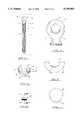
- FIG. 1is a perspective exploded view of the preferred embodiment of the apparatus of the present invention
- FIG. 1Ais a top plan view of the assembled apparatus of FIG. 1;
- FIG. 1Bis a fragmentary side plan view of the assembled apparatus of FIG. 1;
- FIG. 2is a side plan view of the bone screw of the apparatus of the present invention.
- FIG. 3is an enlarged view of a portion of the bone screw of FIG. 2;
- FIG. 4is a side plan view of the collar of the apparatus of the present invention.
- FIG. 5is an enlarged fragmentary view of the collar of FIG. 4;
- FIG. 6is a side plan view of the locking pin of the apparatus of the present invention.
- FIG. 7is an enlarged cross-sectional view looking along the site line 7--7 of FIG. 6;
- FIG. 8is a schematic side view of a partial spinal column with an implanted fixation apparatus of the present invention attached to a portion of spinal rod system;
- FIG. 9is a perspective exploded view of the present invention is use with a portion of a spinal rod system.
- FIG. 10is a side plan view of the fixation apparatus of the present invention secured in a coupler of a spinal rod system.
- FIG. 1illustrates the preferred embodiment of the fixation apparatus of the present invention designated generally by the numeral 10.
- the fixation apparatus 10includes a bone screw 11, a collar 20 and an elongated locking pin 40.
- Bone screw 11has a longitudinal axis 17 and a shank portion 12 with a bone engaging course thread 13 thereon which allows it to be surgically implanted into a patient's bone tissue, and in the preferred embodiment either lumbar or sacral vertebrae (FIGS. 1 and 2).
- a head portion 14has an eyelet 15 with a central bore 16 (FIGS. 1 and 2).
- Bore 16has a surface 16a with a portion of bore surface 16a being textured, preferably at least 30%. In the preferred embodiment the textured surface is formed from regularly spaced teeth 18 as shown in FIGS. 1 and 3.
- Collar 20is generally U-shaped with a transverse axis 21 and a centrally located slot 22 sized and shaped for placing over the eyelet 15 of the screw 11 (FIGS. 1, 1a, 1b and 4).
- Collar 20includes a middle U-shaped portion 24 and extending end portions 26 with the slot 22 positioned in the middle U-shaped portion 24.
- the middle portion 24includes inner walls 28 with flat surfaces on either side of the slot 22.
- a portion of the flat surface of each of the inner walls 28is textured, preferably at least 30% of the surface 28.
- the textured surfaceis comprised of regularly spaced teeth 30 which match and intermesh the regularly spaced teeth 18 on the bore surface 16a of eyelet 15.
- the elongated locking pin 40is generally cylindrical in shape and is sized and shaped to be inserted through the eyelet bore 16 (FIG. 1b).
- Locking pin 40has an outer surface 41 with a portion of the outer surface 41 being textured to provide a gripping surface.
- the textured surfaceincludes regularly spaced longitudinal grooves 42, preferably over at least 30% of the outer surface 41.
- the longitudinal grooves 42 of the locking pin 40are sized and shaped to engage or intermesh with the teeth 18 on the bore surface 16a and the teeth 30 on the inner wall surfaces 28 of the collar 20 (FIG. 1b).
- the teeth 30are aligned on the wall surfaces 28 and the grooves 42 are aligned on the pin surface 41 so as to allow for locking the collar 20 in spaced increments of between about 10° to 20°.
- the fixation apparatus 10 of the present inventionis used in combination with a spinal rod system and is an improvement on the bone screws presently in use.
- the apparatusis used with a Rogozinski Spinal System in which couplers are utilized to make the connection between the vertebrae and the spinal rods.
- the Rogozinski Spinal Systemis described in U.S. Pat. No. 5,102,412 and sold by Smith & Nephew Spine.
- the fixation apparatus 10 of the present inventionaccommodates the difference in angulation found between the sacral vertebrae S and lumbar vertebrae L, as illustrated in FIG. 8, where a difference of angulation defined as X--X, can be approximately 30°.
- FIGS. 9 and 10A spinal system such as the Rogozinski Spinal System is illustrated in FIGS. 9 and 10, where a coupler 44 has a U-shaped open back with aligned side walls 46 and a recess 45 between them for receiving a T-screw.
- An opening 50is in the bottom of the coupler 44 for receiving the threaded shank of a T-screw with the screw head fitting between the side walls of the coupler 44.
- the fixation apparatus 10is pre-assembled such that the collar 20 is placed over the eyelet 15 of the bone screw 11 with the eyelet 15 extending through the slot 22 of the collar 20.
- the pin 40is inserted through the eyelet bore 16 with the pin grooves 42 engaging with the teeth 18 on the bore surface 16a and the pin 40 extending out from both sides of the eyelet bore 16 (FIG. 1b).
- the collar 20is capable of pivoting up and down in a cephalad/caudal plane of the human body or pivoting from side to side in relation to the longitudinal axis 17 of the bone screw 11 (FIG. 1b).
- the preassembled fixation apparatus 10is inserted into the coupler 44 with the collar 20 resting in the recess 45 between the side walls 46 and the threaded shank 12 extending through the opening 50.
- the threaded shank portion 12 of the bone screw 11is then implanted into a patient's vertebrae.
- the extending end portions 26 of the collar 20allow the bone screw 11 to pivot side to side in the coupler 44, in a plane which passes through the longitudinal axis 17 of the bone screw or the medial/lateral plane of the body in relation to the longitudinal axis of the bone screw 11, within a range of generally 140°.
- the collar 20is also capable of pivoting from side to side in relation to the eyelet 15 to adjust for angulation between the longitudinal axis 17 of the implanted bone screw 11 and the transverse axis 21 of the collar 20.
- the adjustability of this angulationis a range of generally 64° in the a plane which intersects the transverse axis 21 of the collar 20 or the cephalad/caudal plane of the body.
- An elongated bar 52is inserted through the aligned openings 48 in the side walls 46 of the coupler 44 holding the apparatus 10 to connect it with a second coupler 44 holding a spinal rod 56 (FIG. 9).
- set screws 54are inserted into openings 58 in the elongated bar 52 in order to tighten the assembly.
- the tightening of the set screw 54pushes down on the screw head 14 and causes the collar 20 to pull up via the coupler's 44 upward force enabling the teeth 30 on the collar 20 to engage with the pin grooves 42 on the pin 40 extending through the eyelet bore 16 to provide a locking means for the apparatus 10.
- the collar teeth 30 and pin grooves 42engage with each other and lock the collar 20 into a selected angled position within a range of 64° (FIG. 10).
- the apparatus 10is formed from stainless steel or other biocompatible material.
- the apparatus 10 of the present inventionallows for angulation in two planes--the medial/lateral and cephalad/caudal plane.
- the intermeshing teeth 18 of the eyelet 14, the teeth 30 of the collar 20 and the grooves 42 of the pin 40provide a locking mechanism or locking means that resists the rotational movement imposed during in vivo loading conditions in the cephalad/caudal plane with an implanted spinal system.
Landscapes
- Health & Medical Sciences (AREA)
- Orthopedic Medicine & Surgery (AREA)
- Life Sciences & Earth Sciences (AREA)
- Neurology (AREA)
- Surgery (AREA)
- Heart & Thoracic Surgery (AREA)
- Engineering & Computer Science (AREA)
- Biomedical Technology (AREA)
- Nuclear Medicine, Radiotherapy & Molecular Imaging (AREA)
- Medical Informatics (AREA)
- Molecular Biology (AREA)
- Animal Behavior & Ethology (AREA)
- General Health & Medical Sciences (AREA)
- Public Health (AREA)
- Veterinary Medicine (AREA)
- Surgical Instruments (AREA)
- Prostheses (AREA)
Abstract
Description
Claims (21)
Priority Applications (5)
| Application Number | Priority Date | Filing Date | Title |
|---|---|---|---|
| US08/200,635US5499983A (en) | 1994-02-23 | 1994-02-23 | Variable angle spinal screw |
| CA002143062ACA2143062A1 (en) | 1994-02-23 | 1995-02-21 | Variable angle spinal screw |
| EP95301167AEP0669108A3 (en) | 1994-02-23 | 1995-02-22 | Variable angle spinal screw. |
| JP7035704AJPH07255739A (en) | 1994-02-23 | 1995-02-23 | Screw for spine of which angle can be changed |
| AU13437/95AAU1343795A (en) | 1994-02-23 | 1995-02-23 | Variable angle spinal screw |
Applications Claiming Priority (1)
| Application Number | Priority Date | Filing Date | Title |
|---|---|---|---|
| US08/200,635US5499983A (en) | 1994-02-23 | 1994-02-23 | Variable angle spinal screw |
Publications (1)
| Publication Number | Publication Date |
|---|---|
| US5499983Atrue US5499983A (en) | 1996-03-19 |
Family
ID=22742541
Family Applications (1)
| Application Number | Title | Priority Date | Filing Date |
|---|---|---|---|
| US08/200,635Expired - LifetimeUS5499983A (en) | 1994-02-23 | 1994-02-23 | Variable angle spinal screw |
Country Status (5)
| Country | Link |
|---|---|
| US (1) | US5499983A (en) |
| EP (1) | EP0669108A3 (en) |
| JP (1) | JPH07255739A (en) |
| AU (1) | AU1343795A (en) |
| CA (1) | CA2143062A1 (en) |
Cited By (79)
| Publication number | Priority date | Publication date | Assignee | Title |
|---|---|---|---|---|
| US5697934A (en)* | 1996-12-02 | 1997-12-16 | Huebner; Randall J. | Tension band wiring pin and method |
| US5738685A (en)* | 1993-05-18 | 1998-04-14 | Schafer Micomed Gmbh | Osteosynthesis device |
| US5741255A (en)* | 1996-06-05 | 1998-04-21 | Acromed Corporation | Spinal column retaining apparatus |
| US5876403A (en)* | 1996-09-06 | 1999-03-02 | Robert Reid Inc. | Bone-fixing devices |
| US5976135A (en)* | 1997-12-18 | 1999-11-02 | Sdgi Holdings, Inc. | Lateral connector assembly |
| US6063090A (en)* | 1996-12-12 | 2000-05-16 | Synthes (U.S.A.) | Device for connecting a longitudinal support to a pedicle screw |
| US6187005B1 (en) | 1998-09-11 | 2001-02-13 | Synthes (Usa) | Variable angle spinal fixation system |
| US6248105B1 (en) | 1997-05-17 | 2001-06-19 | Synthes (U.S.A.) | Device for connecting a longitudinal support with a pedicle screw |
| US6358392B1 (en) | 1998-11-18 | 2002-03-19 | The Johns Hopkins University | Bismuth thin films structure and method of construction |
| US6371957B1 (en) | 1997-01-22 | 2002-04-16 | Synthes (Usa) | Device for connecting a longitudinal bar to a pedicle screw |
| US6398787B1 (en) | 1998-02-18 | 2002-06-04 | Ai Medic Co., Ltd. | Cable sleeve system for bone fixation |
| US20020107573A1 (en)* | 1999-03-07 | 2002-08-08 | Discure Ltd. | Method and apparatus for computerized surgery |
| US20030105460A1 (en)* | 2000-03-15 | 2003-06-05 | Dennis Crandall | Multidirectional pivoting bone screw and fixation system |
| US20030171751A1 (en)* | 2002-02-20 | 2003-09-11 | Stephen Ritland | Pedicle screw connector apparatus and method |
| US20040002708A1 (en)* | 2002-05-08 | 2004-01-01 | Stephen Ritland | Dynamic fixation device and method of use |
| US20040172023A1 (en)* | 2000-06-30 | 2004-09-02 | Stephen Ritland | Polyaxial connection device and method |
| US20040254428A1 (en)* | 2003-05-22 | 2004-12-16 | Stephen Ritland | Intermuscular guide for retractor insertion and method of use |
| US20050065529A1 (en)* | 2003-09-11 | 2005-03-24 | Mingyan Liu | Impulsive percussion instruments for endplate preparation |
| US20050149023A1 (en)* | 2001-09-28 | 2005-07-07 | Stephen Ritland | Adjustable rod and connector device and method of use |
| US6945972B2 (en) | 2000-08-24 | 2005-09-20 | Synthes | Apparatus for connecting a bone fastener to a longitudinal rod |
| US20050234452A1 (en)* | 2004-04-16 | 2005-10-20 | Malandain Hugues F | Subcutaneous support |
| US20050234456A1 (en)* | 2004-04-16 | 2005-10-20 | Malandain Hugues F | Plate system for minimally invasive support of the spine |
| US20050240180A1 (en)* | 2001-09-03 | 2005-10-27 | Cecile Vienney | Spinal osteosynthesis system comprising a support pad |
| US20060009768A1 (en)* | 2002-04-05 | 2006-01-12 | Stephen Ritland | Dynamic fixation device and method of use |
| US20060036242A1 (en)* | 2004-08-10 | 2006-02-16 | Nilsson C M | Screw and rod fixation system |
| US20060064092A1 (en)* | 2001-05-17 | 2006-03-23 | Howland Robert S | Selective axis serrated rod low profile spinal fixation system |
| US20060063978A1 (en)* | 2004-09-20 | 2006-03-23 | Stephen Ritland | Opposing parallel bladed retractor and method of use |
| US20060074419A1 (en)* | 2004-10-05 | 2006-04-06 | Taylor Harold S | Spinal implants with multi-axial anchor assembly and methods |
| US20060079899A1 (en)* | 2001-09-28 | 2006-04-13 | Stephen Ritland | Connection rod for screw or hook polyaxial system and method of use |
| US20060084980A1 (en)* | 2004-10-05 | 2006-04-20 | Melkent Anthony J | Spinal implants and methods with extended multi-axial anchor assemblies |
| US20060095037A1 (en)* | 2004-10-29 | 2006-05-04 | Jones Bryan S | Connector assemblies for connecting a bone anchor to a fixation element |
| US20060149252A1 (en)* | 2004-12-30 | 2006-07-06 | Markworth Aaron D | Bone anchorage screw with built-in hinged plate |
| US20060149237A1 (en)* | 2004-12-30 | 2006-07-06 | Markworth Aaron D | Screw with deployable interlaced dual rods |
| US20060200131A1 (en)* | 2005-03-04 | 2006-09-07 | Depuy Spine Sarl | Constrained motion bone screw assembly |
| US20060200136A1 (en)* | 2005-02-22 | 2006-09-07 | Jackson Roger P | Bone attachment structure with engagement projections |
| US20060200132A1 (en)* | 2005-03-04 | 2006-09-07 | Chao Nam T | Instruments and methods for manipulating a vertebra |
| US20060235389A1 (en)* | 2005-03-03 | 2006-10-19 | Accin Corporation | Spinal stabilization using bone anchor and anchor seat with tangential locking feature |
| US20070043365A1 (en)* | 2005-07-19 | 2007-02-22 | Stephen Ritland | Rod extension for extending fusion construct |
| US20070088357A1 (en)* | 2005-10-18 | 2007-04-19 | Sdgi Holdings, Inc. | Adjustable bone anchor assembly |
| US20070161995A1 (en)* | 2005-10-06 | 2007-07-12 | Trautwein Frank T | Polyaxial Screw |
| US20070173833A1 (en)* | 2006-01-10 | 2007-07-26 | Life Spine, Llc | Pedicle screw constructs and spinal rod attachment assemblies |
| US20070191831A1 (en)* | 2006-01-26 | 2007-08-16 | Depuy Spine, Inc. | System and method for cooling a spinal correction device comprising a shape memory material for corrective spinal surgery |
| US20080051789A1 (en)* | 2006-07-13 | 2008-02-28 | Snyder Brian D | Modular spinal fixation system |
| US20080234759A1 (en)* | 2005-04-27 | 2008-09-25 | Trinity Orthopedics, Llc | Mono-Planar Pedicle Screw Method, System and Kit |
| US20080243194A1 (en)* | 2005-09-26 | 2008-10-02 | The Regents Of The University Of California | Articulating instrumentation for dynamic spinal stabilization |
| US20090228053A1 (en)* | 2008-03-10 | 2009-09-10 | Eric Kolb | Derotation instrument with reduction functionality |
| US20090264933A1 (en)* | 2008-04-22 | 2009-10-22 | Warsaw Orthopedic, Inc. | Anchors for securing a rod to a vertebral member |
| US20090312804A1 (en)* | 2008-06-17 | 2009-12-17 | Thomas Gamache | Adjustable implant assembly |
| US7648520B2 (en) | 2004-04-16 | 2010-01-19 | Kyphon Sarl | Pedicle screw assembly |
| US20100057139A1 (en)* | 2007-06-05 | 2010-03-04 | Spartek Medical, Inc. | Bone anchor for receiving a rod for stabilization and motion preservation spinal implantation system and method |
| US7722651B2 (en) | 2005-10-21 | 2010-05-25 | Depuy Spine, Inc. | Adjustable bone screw assembly |
| US20100137875A1 (en)* | 2008-10-14 | 2010-06-03 | Marino James F | Insertion and reduction tool for pedicle screw assembly |
| US20110077689A1 (en)* | 2009-09-23 | 2011-03-31 | Depuy Spine, Inc. | Methods and Devices for Manipulating a Vertebra |
| US20110112585A1 (en)* | 2006-11-17 | 2011-05-12 | Biedermann Motech Gmbh | Bone anchoring device |
| US20110112578A1 (en)* | 2009-11-09 | 2011-05-12 | Ebi, Llc | Multiplanar bone anchor system |
| US7959564B2 (en) | 2006-07-08 | 2011-06-14 | Stephen Ritland | Pedicle seeker and retractor, and methods of use |
| US20110178558A1 (en)* | 2010-01-15 | 2011-07-21 | Ebi, Llc | Uniplanar bone anchor system |
| US20110178559A1 (en)* | 2010-01-15 | 2011-07-21 | Ebi, Llc | Uniplanar bone anchor system |
| USD642268S1 (en)* | 2009-08-26 | 2011-07-26 | Theken Spine, Llc | Hex rod for spinal surgery |
| FR2958531A1 (en)* | 2010-04-07 | 2011-10-14 | Michel Timoteo | Device for angular indexing of fixation connector of spinal osteosynthesis equipment with respect to spherical head of pedicular screw in bone body of vertebra, has blind housing to completely limit angular displacements of connector |
| US20120029572A1 (en)* | 2010-07-30 | 2012-02-02 | Warsaw Orthopedic, Inc. | Achoring mechanism |
| CN101868187B (en)* | 2007-09-21 | 2013-03-27 | 保罗·塔代乌·马娅·卡瓦利 | Flexible, sliding, dynamic implant system for selective stabilization and correction of spinal deformity and instability |
| US8414614B2 (en) | 2005-10-22 | 2013-04-09 | Depuy International Ltd | Implant kit for supporting a spinal column |
| US8425563B2 (en) | 2006-01-13 | 2013-04-23 | Depuy International Ltd. | Spinal rod support kit |
| US8430914B2 (en) | 2007-10-24 | 2013-04-30 | Depuy Spine, Inc. | Assembly for orthopaedic surgery |
| US20130184760A1 (en)* | 2012-01-12 | 2013-07-18 | Warsaw Orthopedic, Inc | Side loading coronal spinning lateral connector and method |
| US8709015B2 (en) | 2008-03-10 | 2014-04-29 | DePuy Synthes Products, LLC | Bilateral vertebral body derotation system |
| US8998961B1 (en) | 2009-02-26 | 2015-04-07 | Lanx, Inc. | Spinal rod connector and methods |
| US9044272B2 (en) | 2009-11-09 | 2015-06-02 | Ebi, Llc | Multiplanar bone anchor system |
| US9101416B2 (en) | 2003-01-24 | 2015-08-11 | DePuy Synthes Products, Inc. | Spinal rod approximator |
| USRE46115E1 (en) | 2005-09-19 | 2016-08-23 | Ebi, Llc | Bone screw apparatus, system and method |
| US9572599B1 (en)* | 2009-11-11 | 2017-02-21 | Nuvasive, Inc. | Systems and methods for correcting spinal deformities |
| US20170258311A1 (en)* | 2016-02-05 | 2017-09-14 | Karl Storz Gmbh & Co. Kg | Laryngoscope |
| US9907578B2 (en)* | 2008-09-05 | 2018-03-06 | Biedermann Technologies Gmbh & Co. Kg | Bone anchoring element and stabilization device for bones, in particular for the spinal column |
| US9987047B2 (en) | 2013-10-07 | 2018-06-05 | Spine Wave, Inc. | Translating polyaxial screw |
| US10130395B2 (en)* | 2015-08-17 | 2018-11-20 | Globus Medical, Inc. | Modular uniplanar pedicle screw assembly for use with a polyaxial bone fastener |
| CN111278373A (en)* | 2017-10-24 | 2020-06-12 | 马亚·卡瓦利·塔杜·保罗 | Guide device for fixation and penetration of slide knife for dynamic implants |
| US20220047306A1 (en)* | 2005-09-30 | 2022-02-17 | Roger P. Jackson | Dynamic spinal stabilization assemblies, tool set and method |
| US12114899B2 (en) | 2022-06-23 | 2024-10-15 | Warsaw Orthopedic, Inc. | Spinal implant and method |
Families Citing this family (2)
| Publication number | Priority date | Publication date | Assignee | Title |
|---|---|---|---|---|
| SE504379C2 (en)* | 1995-04-10 | 1997-01-27 | Sven Olerud | Locking device for fixing two intersecting rod-shaped implants for position adjustment of vertebrae |
| US9283001B2 (en)* | 2012-01-18 | 2016-03-15 | Globus Medical, Inc. | Systems for spinal stabilization |
Citations (8)
| Publication number | Priority date | Publication date | Assignee | Title |
|---|---|---|---|---|
| US3343612A (en)* | 1965-03-19 | 1967-09-26 | Ira P Flowers | Adapter for posthole digger |
| US4569338A (en)* | 1984-02-09 | 1986-02-11 | Edwards Charles C | Sacral fixation device |
| US4987892A (en)* | 1989-04-04 | 1991-01-29 | Krag Martin H | Spinal fixation device |
| US5053034A (en)* | 1990-08-03 | 1991-10-01 | Sven Olerud | Spinal joint |
| US5176678A (en)* | 1991-03-14 | 1993-01-05 | Tsou Paul M | Orthopaedic device with angularly adjustable anchor attachments to the vertebrae |
| US5209752A (en)* | 1991-12-04 | 1993-05-11 | Danek Medical, Inc. | Lateral offset connector for spinal implant system |
| US5254118A (en)* | 1991-12-04 | 1993-10-19 | Srdjian Mirkovic | Three dimensional spine fixation system |
| US5282801A (en)* | 1993-02-17 | 1994-02-01 | Danek Medical, Inc. | Top tightening clamp assembly for a spinal fixation system |
Family Cites Families (1)
| Publication number | Priority date | Publication date | Assignee | Title |
|---|---|---|---|---|
| FR2681776A1 (en)* | 1991-09-30 | 1993-04-02 | Fixano Sa | VERTEBRAL OSTEOSYNTHESIS DEVICE. |
- 1994
- 1994-02-23USUS08/200,635patent/US5499983A/ennot_activeExpired - Lifetime
- 1995
- 1995-02-21CACA002143062Apatent/CA2143062A1/ennot_activeAbandoned
- 1995-02-22EPEP95301167Apatent/EP0669108A3/ennot_activeWithdrawn
- 1995-02-23AUAU13437/95Apatent/AU1343795A/ennot_activeAbandoned
- 1995-02-23JPJP7035704Apatent/JPH07255739A/enactivePending
Patent Citations (8)
| Publication number | Priority date | Publication date | Assignee | Title |
|---|---|---|---|---|
| US3343612A (en)* | 1965-03-19 | 1967-09-26 | Ira P Flowers | Adapter for posthole digger |
| US4569338A (en)* | 1984-02-09 | 1986-02-11 | Edwards Charles C | Sacral fixation device |
| US4987892A (en)* | 1989-04-04 | 1991-01-29 | Krag Martin H | Spinal fixation device |
| US5053034A (en)* | 1990-08-03 | 1991-10-01 | Sven Olerud | Spinal joint |
| US5176678A (en)* | 1991-03-14 | 1993-01-05 | Tsou Paul M | Orthopaedic device with angularly adjustable anchor attachments to the vertebrae |
| US5209752A (en)* | 1991-12-04 | 1993-05-11 | Danek Medical, Inc. | Lateral offset connector for spinal implant system |
| US5254118A (en)* | 1991-12-04 | 1993-10-19 | Srdjian Mirkovic | Three dimensional spine fixation system |
| US5282801A (en)* | 1993-02-17 | 1994-02-01 | Danek Medical, Inc. | Top tightening clamp assembly for a spinal fixation system |
Cited By (189)
| Publication number | Priority date | Publication date | Assignee | Title |
|---|---|---|---|---|
| US5738685A (en)* | 1993-05-18 | 1998-04-14 | Schafer Micomed Gmbh | Osteosynthesis device |
| US20050197701A1 (en)* | 1995-09-04 | 2005-09-08 | Amiram Steinberg | Method and apparatus for computerized surgery |
| US7497868B2 (en) | 1995-09-04 | 2009-03-03 | Active Implants Corporation | Method and apparatus for computerized surgery |
| US7491219B2 (en) | 1995-09-04 | 2009-02-17 | Active Implants Corporation | Method and apparatus for computerized surgery |
| US20080071374A1 (en)* | 1995-09-04 | 2008-03-20 | Active Implants Corporation | Method and apparatus for computerized surgery |
| US20050177239A1 (en)* | 1995-09-04 | 2005-08-11 | Amiram Steinberg | Method and apparatus for computerized surgery |
| US20070093689A1 (en)* | 1995-09-04 | 2007-04-26 | Active Implants Corporation | Method and apparatus for computerized surgery |
| US5741255A (en)* | 1996-06-05 | 1998-04-21 | Acromed Corporation | Spinal column retaining apparatus |
| US5876403A (en)* | 1996-09-06 | 1999-03-02 | Robert Reid Inc. | Bone-fixing devices |
| US5697934A (en)* | 1996-12-02 | 1997-12-16 | Huebner; Randall J. | Tension band wiring pin and method |
| US6063090A (en)* | 1996-12-12 | 2000-05-16 | Synthes (U.S.A.) | Device for connecting a longitudinal support to a pedicle screw |
| US7022122B2 (en) | 1997-01-22 | 2006-04-04 | Synthes (U.S.A.) | Device for connecting a longitudinal bar to a pedicle screw |
| US20030023240A1 (en)* | 1997-01-22 | 2003-01-30 | Synthes (Usa) | Device for connecting a longitudinal bar to a pedicle screw |
| US6371957B1 (en) | 1997-01-22 | 2002-04-16 | Synthes (Usa) | Device for connecting a longitudinal bar to a pedicle screw |
| US20060149244A1 (en)* | 1997-01-22 | 2006-07-06 | Synthes (Usa) | Device for connecting a longitudinal bar to a pedicle screw |
| US6248105B1 (en) | 1997-05-17 | 2001-06-19 | Synthes (U.S.A.) | Device for connecting a longitudinal support with a pedicle screw |
| US5976135A (en)* | 1997-12-18 | 1999-11-02 | Sdgi Holdings, Inc. | Lateral connector assembly |
| US6398787B1 (en) | 1998-02-18 | 2002-06-04 | Ai Medic Co., Ltd. | Cable sleeve system for bone fixation |
| US6187005B1 (en) | 1998-09-11 | 2001-02-13 | Synthes (Usa) | Variable angle spinal fixation system |
| US6358392B1 (en) | 1998-11-18 | 2002-03-19 | The Johns Hopkins University | Bismuth thin films structure and method of construction |
| US9668875B2 (en) | 1999-03-07 | 2017-06-06 | Nuvasive, Inc. | Method and apparatus for computerized surgery |
| US20020107573A1 (en)* | 1999-03-07 | 2002-08-08 | Discure Ltd. | Method and apparatus for computerized surgery |
| US7338526B2 (en) | 1999-03-07 | 2008-03-04 | Active Implants Corporation | Method and apparatus for computerized surgery |
| US9017313B2 (en) | 1999-03-07 | 2015-04-28 | Nuvasive, Inc. | Method and apparatus for computerized surgery |
| US9827109B2 (en) | 1999-03-07 | 2017-11-28 | Nuvasive, Inc. | Methods and apparatus for performing spine surgery |
| US20030105460A1 (en)* | 2000-03-15 | 2003-06-05 | Dennis Crandall | Multidirectional pivoting bone screw and fixation system |
| US7322979B2 (en)* | 2000-03-15 | 2008-01-29 | Warsaw Orthopedic, Inc. | Multidirectional pivoting bone screw and fixation system |
| US7753939B2 (en) | 2000-06-30 | 2010-07-13 | Stephen Ritland | Polyaxial connection device and method |
| US20040172023A1 (en)* | 2000-06-30 | 2004-09-02 | Stephen Ritland | Polyaxial connection device and method |
| US6945972B2 (en) | 2000-08-24 | 2005-09-20 | Synthes | Apparatus for connecting a bone fastener to a longitudinal rod |
| US20050251141A1 (en)* | 2000-08-24 | 2005-11-10 | Synthes Usa | Apparatus for connecting a bone fastener to a longitudinal rod |
| US20060064092A1 (en)* | 2001-05-17 | 2006-03-23 | Howland Robert S | Selective axis serrated rod low profile spinal fixation system |
| US20050240180A1 (en)* | 2001-09-03 | 2005-10-27 | Cecile Vienney | Spinal osteosynthesis system comprising a support pad |
| US9622790B2 (en) | 2001-09-19 | 2017-04-18 | Warsaw Orthopedic, Inc. | Rod extension for extending fusion construct |
| US7695498B2 (en) | 2001-09-28 | 2010-04-13 | Stephen Ritland | Connection rod for screw or hook polyaxial system and method of use |
| US7207992B2 (en) | 2001-09-28 | 2007-04-24 | Stephen Ritland | Connection rod for screw or hook polyaxial system and method of use |
| US7985245B2 (en) | 2001-09-28 | 2011-07-26 | Stephen Ritland | Connection rod for screw or hook polyaxial system and method of use |
| US20060079899A1 (en)* | 2001-09-28 | 2006-04-13 | Stephen Ritland | Connection rod for screw or hook polyaxial system and method of use |
| US20050149023A1 (en)* | 2001-09-28 | 2005-07-07 | Stephen Ritland | Adjustable rod and connector device and method of use |
| US7655025B2 (en) | 2001-09-28 | 2010-02-02 | Stephen Ritland | Adjustable rod and connector device and method of use |
| US20100137914A1 (en)* | 2001-09-28 | 2010-06-03 | Stephen Ritland | Adjustable rod and connector device |
| US8221459B2 (en) | 2002-02-20 | 2012-07-17 | Stephen Ritland | Pedicle screw connector apparatus and method |
| US20030171751A1 (en)* | 2002-02-20 | 2003-09-11 | Stephen Ritland | Pedicle screw connector apparatus and method |
| US7763047B2 (en)* | 2002-02-20 | 2010-07-27 | Stephen Ritland | Pedicle screw connector apparatus and method |
| US20110022094A1 (en)* | 2002-02-20 | 2011-01-27 | Stephen Ritland | Pedicle Screw Connector Apparatus and Method |
| US8932334B2 (en) | 2002-04-05 | 2015-01-13 | Stephen Ritland | Dynamic fixation device and method of use |
| US20060009768A1 (en)* | 2002-04-05 | 2006-01-12 | Stephen Ritland | Dynamic fixation device and method of use |
| US8690922B2 (en) | 2002-05-08 | 2014-04-08 | Stephen Ritland | Dynamic fixation device and method of use |
| US7682375B2 (en) | 2002-05-08 | 2010-03-23 | Stephen Ritland | Dynamic fixation device and method of use |
| US20070016193A1 (en)* | 2002-05-08 | 2007-01-18 | Stephen Ritland | Dynamic fixation device and method of use |
| US20100174318A1 (en)* | 2002-05-08 | 2010-07-08 | Stephen Ritland | Dynamic Fixation Device and Method of Use |
| US20040002708A1 (en)* | 2002-05-08 | 2004-01-01 | Stephen Ritland | Dynamic fixation device and method of use |
| US8486111B2 (en) | 2002-05-08 | 2013-07-16 | Stephen Ritland | Dynamic fixation device and method of use |
| US9918744B2 (en) | 2002-05-08 | 2018-03-20 | Stephen Ritland | Dynamic fixation device and method of use |
| US9232967B2 (en) | 2002-05-08 | 2016-01-12 | Stephen Ritland | Dynamic fixation device and method of use |
| US8585739B2 (en) | 2002-05-08 | 2013-11-19 | Stephen Ritland | Dynamic fixation device and method of use |
| US8685062B2 (en) | 2002-05-08 | 2014-04-01 | Stephen Ritland | Dynamic fixation device and method of use |
| US20100179596A1 (en)* | 2002-05-08 | 2010-07-15 | Stephen Ritland | Dynamic Fixation Device and Method of Use |
| US9101416B2 (en) | 2003-01-24 | 2015-08-11 | DePuy Synthes Products, Inc. | Spinal rod approximator |
| US20040254428A1 (en)* | 2003-05-22 | 2004-12-16 | Stephen Ritland | Intermuscular guide for retractor insertion and method of use |
| US8262571B2 (en) | 2003-05-22 | 2012-09-11 | Stephen Ritland | Intermuscular guide for retractor insertion and method of use |
| US20050065529A1 (en)* | 2003-09-11 | 2005-03-24 | Mingyan Liu | Impulsive percussion instruments for endplate preparation |
| US20100076494A1 (en)* | 2004-04-16 | 2010-03-25 | Kyphon Sarl | Pedicle screw assembly |
| US7524323B2 (en) | 2004-04-16 | 2009-04-28 | Kyphon Sarl | Subcutaneous support |
| US20050234452A1 (en)* | 2004-04-16 | 2005-10-20 | Malandain Hugues F | Subcutaneous support |
| US7618418B2 (en) | 2004-04-16 | 2009-11-17 | Kyphon Sarl | Plate system for minimally invasive support of the spine |
| US20050234456A1 (en)* | 2004-04-16 | 2005-10-20 | Malandain Hugues F | Plate system for minimally invasive support of the spine |
| US7648520B2 (en) | 2004-04-16 | 2010-01-19 | Kyphon Sarl | Pedicle screw assembly |
| US20060036242A1 (en)* | 2004-08-10 | 2006-02-16 | Nilsson C M | Screw and rod fixation system |
| US7766945B2 (en) | 2004-08-10 | 2010-08-03 | Lanx, Inc. | Screw and rod fixation system |
| US20060063978A1 (en)* | 2004-09-20 | 2006-03-23 | Stephen Ritland | Opposing parallel bladed retractor and method of use |
| US7455639B2 (en) | 2004-09-20 | 2008-11-25 | Stephen Ritland | Opposing parallel bladed retractor and method of use |
| US20060074419A1 (en)* | 2004-10-05 | 2006-04-06 | Taylor Harold S | Spinal implants with multi-axial anchor assembly and methods |
| AU2005294535B2 (en)* | 2004-10-05 | 2012-01-19 | Warsaw Orthopedic, Inc. | Multi-axial anchor assemblies for spinal implants and methods |
| US20060084980A1 (en)* | 2004-10-05 | 2006-04-20 | Melkent Anthony J | Spinal implants and methods with extended multi-axial anchor assemblies |
| US7722654B2 (en)* | 2004-10-05 | 2010-05-25 | Warsaw Orthopedic, Inc. | Spinal implants with multi-axial anchor assembly and methods |
| US7794477B2 (en) | 2004-10-05 | 2010-09-14 | Warsaw Orthopedic, Inc. | Spinal implants and methods with extended multi-axial anchor assemblies |
| US20100318132A1 (en)* | 2004-10-05 | 2010-12-16 | Warsaw Orthopedic, Inc. | Spinal Implants and Methods With Extended Multi-Axial Anchor Assemblies |
| US8012188B2 (en)* | 2004-10-05 | 2011-09-06 | Warsaw Orthopedic, Inc. | Spinal implants and methods with extended multi-axial anchor assemblies |
| US20060095037A1 (en)* | 2004-10-29 | 2006-05-04 | Jones Bryan S | Connector assemblies for connecting a bone anchor to a fixation element |
| US20060149237A1 (en)* | 2004-12-30 | 2006-07-06 | Markworth Aaron D | Screw with deployable interlaced dual rods |
| US20060149252A1 (en)* | 2004-12-30 | 2006-07-06 | Markworth Aaron D | Bone anchorage screw with built-in hinged plate |
| US7811311B2 (en)* | 2004-12-30 | 2010-10-12 | Warsaw Orthopedic, Inc. | Screw with deployable interlaced dual rods |
| US7789899B2 (en) | 2004-12-30 | 2010-09-07 | Warsaw Orthopedic, Inc. | Bone anchorage screw with built-in hinged plate |
| US20060200136A1 (en)* | 2005-02-22 | 2006-09-07 | Jackson Roger P | Bone attachment structure with engagement projections |
| US20060235389A1 (en)* | 2005-03-03 | 2006-10-19 | Accin Corporation | Spinal stabilization using bone anchor and anchor seat with tangential locking feature |
| US8167913B2 (en)* | 2005-03-03 | 2012-05-01 | Altus Partners, Llc | Spinal stabilization using bone anchor and anchor seat with tangential locking feature |
| US20060200132A1 (en)* | 2005-03-04 | 2006-09-07 | Chao Nam T | Instruments and methods for manipulating a vertebra |
| US9095379B2 (en) | 2005-03-04 | 2015-08-04 | Medos International Sarl | Constrained motion bone screw assembly |
| US10172648B2 (en) | 2005-03-04 | 2019-01-08 | Medos International Sarl | Constrained motion bone screw assembly |
| US8709044B2 (en) | 2005-03-04 | 2014-04-29 | DePuy Synthes Products, LLC | Instruments and methods for manipulating vertebra |
| US11000315B2 (en) | 2005-03-04 | 2021-05-11 | Medos International Sarl | Constrained motion bone screw assembly |
| US20060200131A1 (en)* | 2005-03-04 | 2006-09-07 | Depuy Spine Sarl | Constrained motion bone screw assembly |
| US11446066B2 (en) | 2005-03-04 | 2022-09-20 | DePuy Synthes Products, Inc. | Instruments and methods for manipulating vertebra |
| US10314624B2 (en) | 2005-03-04 | 2019-06-11 | DePuy Synthes Products, Inc. | Instruments and methods for manipulating vertebra |
| US11849978B2 (en) | 2005-03-04 | 2023-12-26 | Medos International Sarl | Constrained motion bone screw assembly |
| US7951168B2 (en) | 2005-03-04 | 2011-05-31 | Depuy Spine, Inc. | Instruments and methods for manipulating vertebra |
| US8007516B2 (en) | 2005-03-04 | 2011-08-30 | Depuy Spine, Inc. | Instruments and methods for manipulating vertebra |
| US7951175B2 (en) | 2005-03-04 | 2011-05-31 | Depuy Spine, Inc. | Instruments and methods for manipulating a vertebra |
| US7951172B2 (en) | 2005-03-04 | 2011-05-31 | Depuy Spine Sarl | Constrained motion bone screw assembly |
| US20110196431A1 (en)* | 2005-03-04 | 2011-08-11 | Depuy Spine Sarl | Constrained motion bone screw assembly |
| US9795416B2 (en) | 2005-03-04 | 2017-10-24 | Medos International Sárl | Constrained motion bone screw assembly |
| US20070162009A1 (en)* | 2005-03-04 | 2007-07-12 | Chao Nam T | Instruments and methods for manipulating vertebra |
| WO2006116606A3 (en)* | 2005-04-27 | 2009-04-16 | James Marino | Mono-planar pedilcle screw method, system, and kit |
| US20100298890A1 (en)* | 2005-04-27 | 2010-11-25 | James Marino | Mono-planar pedicle screw method, system and kit |
| US7780706B2 (en)* | 2005-04-27 | 2010-08-24 | Trinity Orthopedics, Llc | Mono-planar pedicle screw method, system and kit |
| US20080234759A1 (en)* | 2005-04-27 | 2008-09-25 | Trinity Orthopedics, Llc | Mono-Planar Pedicle Screw Method, System and Kit |
| US8298268B2 (en) | 2005-04-27 | 2012-10-30 | Trinty Orthopedics, LLC. | Mono-planar pedicle screw method, system and kit |
| US8845694B2 (en) | 2005-07-19 | 2014-09-30 | Warsaw Orthopedic, Inc. | Rod extension for extending fusion construct |
| US8021399B2 (en) | 2005-07-19 | 2011-09-20 | Stephen Ritland | Rod extension for extending fusion construct |
| US20070043365A1 (en)* | 2005-07-19 | 2007-02-22 | Stephen Ritland | Rod extension for extending fusion construct |
| USRE46115E1 (en) | 2005-09-19 | 2016-08-23 | Ebi, Llc | Bone screw apparatus, system and method |
| US20080243194A1 (en)* | 2005-09-26 | 2008-10-02 | The Regents Of The University Of California | Articulating instrumentation for dynamic spinal stabilization |
| US20220047306A1 (en)* | 2005-09-30 | 2022-02-17 | Roger P. Jackson | Dynamic spinal stabilization assemblies, tool set and method |
| US7927359B2 (en) | 2005-10-06 | 2011-04-19 | Paradigm Spine, Llc | Polyaxial screw |
| US8470001B2 (en) | 2005-10-06 | 2013-06-25 | Paradigm Spine, Llc | Polyaxial screw |
| US20070161995A1 (en)* | 2005-10-06 | 2007-07-12 | Trautwein Frank T | Polyaxial Screw |
| US20070088357A1 (en)* | 2005-10-18 | 2007-04-19 | Sdgi Holdings, Inc. | Adjustable bone anchor assembly |
| US9155566B2 (en) | 2005-10-18 | 2015-10-13 | Warsaw Orthopedic, Inc. | Adjustable bone anchor assembly |
| US8075599B2 (en) | 2005-10-18 | 2011-12-13 | Warsaw Orthopedic, Inc. | Adjustable bone anchor assembly |
| US8603144B2 (en) | 2005-10-21 | 2013-12-10 | DePuy Synthes Products, LLC | Adjustable bone screw assembly |
| US7722651B2 (en) | 2005-10-21 | 2010-05-25 | Depuy Spine, Inc. | Adjustable bone screw assembly |
| US20100198273A1 (en)* | 2005-10-21 | 2010-08-05 | Kwak Seungkyu Daniel | Adjustable bone screw assembly |
| US8845700B2 (en) | 2005-10-21 | 2014-09-30 | DePuy Synthes Products, LLC. | Adjustable bone screw assembly |
| US7951174B2 (en) | 2005-10-21 | 2011-05-31 | Depuy Spine, Inc. | Adjustable bone screw assembly |
| US20110208250A1 (en)* | 2005-10-21 | 2011-08-25 | Depuy Spine, Inc. | Adjustable bone screw assembly |
| US8414614B2 (en) | 2005-10-22 | 2013-04-09 | Depuy International Ltd | Implant kit for supporting a spinal column |
| US20070173833A1 (en)* | 2006-01-10 | 2007-07-26 | Life Spine, Llc | Pedicle screw constructs and spinal rod attachment assemblies |
| US8663287B2 (en)* | 2006-01-10 | 2014-03-04 | Life Spine, Inc. | Pedicle screw constructs and spinal rod attachment assemblies |
| US8425563B2 (en) | 2006-01-13 | 2013-04-23 | Depuy International Ltd. | Spinal rod support kit |
| US8348952B2 (en) | 2006-01-26 | 2013-01-08 | Depuy International Ltd. | System and method for cooling a spinal correction device comprising a shape memory material for corrective spinal surgery |
| US20070191831A1 (en)* | 2006-01-26 | 2007-08-16 | Depuy Spine, Inc. | System and method for cooling a spinal correction device comprising a shape memory material for corrective spinal surgery |
| US7959564B2 (en) | 2006-07-08 | 2011-06-14 | Stephen Ritland | Pedicle seeker and retractor, and methods of use |
| US20080051789A1 (en)* | 2006-07-13 | 2008-02-28 | Snyder Brian D | Modular spinal fixation system |
| US7785352B2 (en)* | 2006-07-13 | 2010-08-31 | Mass Modular Spine Group, Inc. | Modular spinal fixation system |
| US20110112585A1 (en)* | 2006-11-17 | 2011-05-12 | Biedermann Motech Gmbh | Bone anchoring device |
| TWI418329B (en)* | 2006-11-17 | 2013-12-11 | Biedermann Technologies Gmbh | Bone anchoring device |
| US8998965B2 (en)* | 2006-11-17 | 2015-04-07 | Biedermann Technologies Gmbh & Co. Kg | Bone anchoring device |
| US20100057139A1 (en)* | 2007-06-05 | 2010-03-04 | Spartek Medical, Inc. | Bone anchor for receiving a rod for stabilization and motion preservation spinal implantation system and method |
| US8568451B2 (en)* | 2007-06-05 | 2013-10-29 | Spartek Medical, Inc. | Bone anchor for receiving a rod for stabilization and motion preservation spinal implantation system and method |
| US8317836B2 (en)* | 2007-06-05 | 2012-11-27 | Spartek Medical, Inc. | Bone anchor for receiving a rod for stabilization and motion preservation spinal implantation system and method |
| US20100057140A1 (en)* | 2007-06-05 | 2010-03-04 | Spartek Medical, Inc. | Bone anchor for receiving a rod for stabilization and motion preservation spinal implantation system and method |
| CN101868187B (en)* | 2007-09-21 | 2013-03-27 | 保罗·塔代乌·马娅·卡瓦利 | Flexible, sliding, dynamic implant system for selective stabilization and correction of spinal deformity and instability |
| US8430914B2 (en) | 2007-10-24 | 2013-04-30 | Depuy Spine, Inc. | Assembly for orthopaedic surgery |
| US8709015B2 (en) | 2008-03-10 | 2014-04-29 | DePuy Synthes Products, LLC | Bilateral vertebral body derotation system |
| US20090228053A1 (en)* | 2008-03-10 | 2009-09-10 | Eric Kolb | Derotation instrument with reduction functionality |
| US8608746B2 (en) | 2008-03-10 | 2013-12-17 | DePuy Synthes Products, LLC | Derotation instrument with reduction functionality |
| US9326798B2 (en) | 2008-03-10 | 2016-05-03 | DePuy Synthes Products, Inc. | Derotation instrument with reduction functionality |
| US20090264933A1 (en)* | 2008-04-22 | 2009-10-22 | Warsaw Orthopedic, Inc. | Anchors for securing a rod to a vertebral member |
| US11992245B2 (en) | 2008-06-17 | 2024-05-28 | DePuy Synthes Products, Inc. | Adjustable implant assembly |
| US20090312804A1 (en)* | 2008-06-17 | 2009-12-17 | Thomas Gamache | Adjustable implant assembly |
| US10973556B2 (en) | 2008-06-17 | 2021-04-13 | DePuy Synthes Products, Inc. | Adjustable implant assembly |
| US9907578B2 (en)* | 2008-09-05 | 2018-03-06 | Biedermann Technologies Gmbh & Co. Kg | Bone anchoring element and stabilization device for bones, in particular for the spinal column |
| US20100137875A1 (en)* | 2008-10-14 | 2010-06-03 | Marino James F | Insertion and reduction tool for pedicle screw assembly |
| US8460308B2 (en) | 2008-10-14 | 2013-06-11 | Trinity Orthopedics, Llc. | Insertion and reduction tool for pedicle screw assembly |
| US8998961B1 (en) | 2009-02-26 | 2015-04-07 | Lanx, Inc. | Spinal rod connector and methods |
| USD642268S1 (en)* | 2009-08-26 | 2011-07-26 | Theken Spine, Llc | Hex rod for spinal surgery |
| US9339308B2 (en)* | 2009-09-23 | 2016-05-17 | DePuy Synthes Products, Inc. | Methods and devices for manipulating a vertebra |
| US9949767B2 (en) | 2009-09-23 | 2018-04-24 | DePuy Synthes Products, Inc. | Methods and devices for manipulating a vertebra |
| US20110077689A1 (en)* | 2009-09-23 | 2011-03-31 | Depuy Spine, Inc. | Methods and Devices for Manipulating a Vertebra |
| US10729471B2 (en) | 2009-11-09 | 2020-08-04 | Ebi, Llc | Multiplanar bone anchor system |
| US20110112578A1 (en)* | 2009-11-09 | 2011-05-12 | Ebi, Llc | Multiplanar bone anchor system |
| US9044272B2 (en) | 2009-11-09 | 2015-06-02 | Ebi, Llc | Multiplanar bone anchor system |
| US11806051B2 (en) | 2009-11-09 | 2023-11-07 | Ebi, Llc | Multiplanar bone anchor system |
| US9763701B2 (en) | 2009-11-09 | 2017-09-19 | Ebi, Llc | Multiplanar bone anchor system |
| US8449578B2 (en)* | 2009-11-09 | 2013-05-28 | Ebi, Llc | Multiplanar bone anchor system |
| US10456173B1 (en) | 2009-11-11 | 2019-10-29 | Nuvasive, Inc. | Systems and methods for correcting spinal deformities |
| US9572599B1 (en)* | 2009-11-11 | 2017-02-21 | Nuvasive, Inc. | Systems and methods for correcting spinal deformities |
| US11490931B2 (en) | 2009-11-11 | 2022-11-08 | Nuvasive, Inc. | Systems and methods for correcting spinal deformities |
| US8419778B2 (en)* | 2010-01-15 | 2013-04-16 | Ebi, Llc | Uniplanar bone anchor system |
| US9211143B2 (en)* | 2010-01-15 | 2015-12-15 | Ebi, Llc | Uniplanar bone anchor system |
| US20140148862A1 (en)* | 2010-01-15 | 2014-05-29 | Ebi, Llc | Uniplanar bone anchor system |
| US20110178559A1 (en)* | 2010-01-15 | 2011-07-21 | Ebi, Llc | Uniplanar bone anchor system |
| US8986356B2 (en) | 2010-01-15 | 2015-03-24 | Ebi, Llc | Uniplanar bone anchor system |
| US20110178558A1 (en)* | 2010-01-15 | 2011-07-21 | Ebi, Llc | Uniplanar bone anchor system |
| US9820781B2 (en) | 2010-01-15 | 2017-11-21 | Ebi, Llc | Uniplanar bone anchor system |
| US8647370B2 (en) | 2010-01-15 | 2014-02-11 | Ebi, Llc | Uniplanar bone anchor system |
| FR2958531A1 (en)* | 2010-04-07 | 2011-10-14 | Michel Timoteo | Device for angular indexing of fixation connector of spinal osteosynthesis equipment with respect to spherical head of pedicular screw in bone body of vertebra, has blind housing to completely limit angular displacements of connector |
| US20120029572A1 (en)* | 2010-07-30 | 2012-02-02 | Warsaw Orthopedic, Inc. | Achoring mechanism |
| US8231659B2 (en)* | 2010-07-30 | 2012-07-31 | Warsaw Orthopedic | Anchoring mechanism |
| US20130184760A1 (en)* | 2012-01-12 | 2013-07-18 | Warsaw Orthopedic, Inc | Side loading coronal spinning lateral connector and method |
| US9987047B2 (en) | 2013-10-07 | 2018-06-05 | Spine Wave, Inc. | Translating polyaxial screw |
| US10278741B2 (en) | 2013-10-07 | 2019-05-07 | Spine Wave, Inc. | Translating polyaxial screw |
| US10130395B2 (en)* | 2015-08-17 | 2018-11-20 | Globus Medical, Inc. | Modular uniplanar pedicle screw assembly for use with a polyaxial bone fastener |
| US10368730B2 (en)* | 2016-02-05 | 2019-08-06 | Karl Storz Se & Co. Kg | Laryngoscope |
| US20170258311A1 (en)* | 2016-02-05 | 2017-09-14 | Karl Storz Gmbh & Co. Kg | Laryngoscope |
| CN111278373A (en)* | 2017-10-24 | 2020-06-12 | 马亚·卡瓦利·塔杜·保罗 | Guide device for fixation and penetration of slide knife for dynamic implants |
| CN111278373B (en)* | 2017-10-24 | 2023-10-03 | 马亚·卡瓦利·塔杜·保罗 | Guiding device for fixation and penetration of a sliding blade of a dynamic implant |
| US12114899B2 (en) | 2022-06-23 | 2024-10-15 | Warsaw Orthopedic, Inc. | Spinal implant and method |
Also Published As
| Publication number | Publication date |
|---|---|
| EP0669108A3 (en) | 1996-01-03 |
| AU1343795A (en) | 1995-08-31 |
| CA2143062A1 (en) | 1995-08-24 |
| EP0669108A2 (en) | 1995-08-30 |
| JPH07255739A (en) | 1995-10-09 |
Similar Documents
| Publication | Publication Date | Title |
|---|---|---|
| US5499983A (en) | Variable angle spinal screw | |
| US7699872B2 (en) | Posterior fixation system | |
| US5527314A (en) | Spinal fixation system | |
| USRE39035E1 (en) | Universal coupler for spinal fixation | |
| US8728080B2 (en) | Spinal fixation plates and plate extensions | |
| US6413257B1 (en) | Clamping connector for spinal fixation systems | |
| EP1635722B1 (en) | Variable offset spinal fixation system | |
| EP1152705B1 (en) | Spinal fixation system | |
| US5947966A (en) | Device for linking adjacent rods in spinal instrumentation | |
| US8512380B2 (en) | Posterior fixation system | |
| JP3776456B2 (en) | Bone fixation device to fix the upper part | |
| US6402751B1 (en) | Device for linking adjacent rods in spinal instrumentation | |
| US6287308B1 (en) | Methods and apparatus for fusionless treatment of spinal deformities | |
| US5628740A (en) | Articulating toggle bolt bone screw | |
| EP1263338B1 (en) | Spinal implant connection assembly | |
| US7901433B2 (en) | Occipito-cervical stabilization system and method | |
| US8226689B2 (en) | Apparatus and methods for spinal implant with variable link mechanism | |
| EP1346708A1 (en) | Three-hooked device for fixing spinal column | |
| AU2001289108A1 (en) | Posterior fixation system | |
| CA2583093C (en) | Posterior fixation system |
Legal Events
| Date | Code | Title | Description |
|---|---|---|---|
| AS | Assignment | Owner name:SMITH & NEPHEW RICHARDS, INC., TENNESSEE Free format text:ASSIGNMENT OF ASSIGNORS INTEREST;ASSIGNOR:HUGHES, DEAN;REEL/FRAME:006966/0705 | |
| STCF | Information on status: patent grant | Free format text:PATENTED CASE | |
| AS | Assignment | Owner name:UNITED STATES SURGICAL CORPORATION, CONNECTICUT Free format text:ASSIGNMENT OF ASSIGNORS INTEREST;ASSIGNOR:SMITH & NEPHEW, INC.;REEL/FRAME:008989/0392 Effective date:19970917 Owner name:SURGICAL DYNAMICS, INC., CONNECTICUT Free format text:ASSIGNMENT OF ASSIGNORS INTEREST;ASSIGNOR:UNITED STATES SURGICAL CORPORATION;REEL/FRAME:008989/0398 Effective date:19980213 | |
| FPAY | Fee payment | Year of fee payment:4 | |
| AS | Assignment | Owner name:SMITH & NEPHEW, INC., TENNESSEE Free format text:MERGER;ASSIGNOR:SMITH & NEPHEW RICHARDS INC.;REEL/FRAME:013169/0305 Effective date:19961126 | |
| AS | Assignment | Owner name:HOWMEDICA OSTEONICS CORP., NEW JERSEY Free format text:MERGER;ASSIGNOR:SURGICAL DYNAMICS INC.;REEL/FRAME:013193/0337 Effective date:20020701 | |
| FPAY | Fee payment | Year of fee payment:8 | |
| FPAY | Fee payment | Year of fee payment:12 |