US5499784A - Flight refuelling system - Google Patents
Flight refuelling systemDownload PDFInfo
- Publication number
- US5499784A US5499784AUS08/241,018US24101894AUS5499784AUS 5499784 AUS5499784 AUS 5499784AUS 24101894 AUS24101894 AUS 24101894AUS 5499784 AUS5499784 AUS 5499784A
- Authority
- US
- United States
- Prior art keywords
- aircraft
- fuel
- refuelling
- refueling
- telescopic tube
- Prior art date
- Legal status (The legal status is an assumption and is not a legal conclusion. Google has not performed a legal analysis and makes no representation as to the accuracy of the status listed.)
- Expired - Lifetime
Links
Images


Classifications
- B—PERFORMING OPERATIONS; TRANSPORTING
- B64—AIRCRAFT; AVIATION; COSMONAUTICS
- B64D—EQUIPMENT FOR FITTING IN OR TO AIRCRAFT; FLIGHT SUITS; PARACHUTES; ARRANGEMENT OR MOUNTING OF POWER PLANTS OR PROPULSION TRANSMISSIONS IN AIRCRAFT
- B64D39/00—Refuelling during flight
- B—PERFORMING OPERATIONS; TRANSPORTING
- B64—AIRCRAFT; AVIATION; COSMONAUTICS
- B64D—EQUIPMENT FOR FITTING IN OR TO AIRCRAFT; FLIGHT SUITS; PARACHUTES; ARRANGEMENT OR MOUNTING OF POWER PLANTS OR PROPULSION TRANSMISSIONS IN AIRCRAFT
- B64D43/00—Arrangements or adaptations of instruments
Definitions
- the inventionrelates to a flight refuelling system. Such a system permits the transfer of fuel from the tanks of a refuelling aircraft to the tanks of a refuelled aircraft.
- a refuelling aircraftperforms its missions by day and night with the aid of devices which can be installed, separately or jointly, as a function of the needs of the user.
- said devicescomprise:
- refuelling podsgenerally positioned below the wing and permitting the unwinding of a hose provided with a basket member and the refuelling of aircraft equipped with a probe;
- telescopic tubebeneath the fuselage and controllable in azimuth, elevation and distance, so as to permit the refuelling of aircraft equipped with a receptacle.
- a British Aerospace VC10 aircraftcan have two underslung pods, a winch beneath the fuselage and a probe. This aircraft has wing fuel tanks and supplementary tanks in the fuselage. Its working station is in the cockpit (extension of the mechanic's station of the non-refuelling VC10).
- the operator checking meansare on two panels and among other instruments.
- a telescopic tube beneath the fuselageis associated with a working station.
- the operator lying flat on his stomachlooks through a fuselage opening provided with a window.
- the tubecan be engaged beneath the fuselage in the non-refuelling phase.
- a handlemakes it possible to control this tube manually by a mechanical connection using mobile hydraulic control surfaces.
- Various circular dialsmake it possible to monitor the operation (azimuth indicator, etc.).
- a Douglas KC10 aircrafthas a winch beneath the fuselage, a telescopic tube and a working station to the rear of the fuselage.
- the tubeis manually controlled by electric control means.
- the installation of the telescopic tube developed by the Israel Aircraft Industryis associated with the putting into place of three cameras, two beneath the fuselage to give vision of the receptacle of the refuelled aircraft in relief and one below the tube in order to obtain better accuracy in the final control phase (docking of the end of the telescopic tube and the receptacle); a working station equipped with two cathode screens, each connected to one of the two cameras installed beneath the fuselage and associated with a combining means which superimposes the two images by polarizing them in two perpendicular directions.
- the operatorsees with each of his eyes the image given by the camera located on the same side, so that he has a three-dimensional vision of the outside world and in particular the refuelled aircraft.
- the control of the tubeis similar to that of the Boeing KC135.
- either the intermediate fuel intake meansis a probe installed at the front of the first aircraft and the intermediate fuel supply means is a refuelling pod installed below the wing or a winch installed beneath the fuselage of the second aircraft;
- the intermediate fuel intake meansis a receptacle located on the upper portion of the first aircraft and the intermediate fuel supply means is a telescopic tube positioned below the fuselage of the second aircraft and in this case a camera is advantageously located on the telescopic tube.
- said interfaceis located in the cockpit or in the fuselage, so that there are two possible working stations.
- the locationis at the front, but the human-machine interface overlaps with the checking means of other systems.
- the operatorIn the case where the operator is at the rear, he only has a limited number of informations, mainly those associated with the control of the telescopic tube or the unwinding of the winch, e.g. having only few informations concerning the fuel.
- the IAI solutionpermits the recording and reading of the stored refuelling phases by means of cameras in the way in which they were seen by the operator.
- a single working statione.g. in the cockpit area, is required, so that the operator and crew are then in visual contact;
- the checking meansare located in front of the operator and the operations can be organized by phase and subphase (e.g. the tube control subphase is not presented, monitored and controlled except before telescopic tube-receptacle contact);
- supplementary informationscan be made available to the operator to enable him to better follow the refuelling operation. He can e.g. have a complete display of the fuel system of any aircraft, messages indicating the procedure to be followed or informing him of a breakdown in another aircraft system such as the hydraulic system, so that the fuel pumps can be turned;
- the systemmakes it possible to give the operator an e.g. navigator function, so as to complete the activities of the flight crew;
- the system according to the inventionfavours a greater automation of the flight refuelling operation, e.g. for the control of the telescopic tube, so that the operator's workload can be reduced.
- the inventionrelates to a system for the flight refuelling of at least one first aircraft, equipped with an intermediate fuel intake means connected to at least one tank, by a second aircraft, equipped with an intermediate fuel supply means connected to at least one tank and which can be connected to the intermediate intake means so as to permit, with the aid of at least one fuel pump, the transfer of the fuel contained in the tank or tanks of the second aircraft to the tank or tanks of the first aircraft, characterized in that it comprises at least one camera positioned below the fuselage of the second aircraft, at least one multimode display making it possible to display at the same time at least one image from a camera and/or at least one symbology, which is a diagrammatic representation of the operation of certain devices of the second aircraft used during the refuelling operation, at least one multifunction equipment incorporating a screen and a keyboard making it possible to perform several operations, so as to render possible the installation in a single working station, within the second aircraft, of all the instruments necessary for the operator to check the flight refuelling of the first aircraft.
- the symbologycan be associated with the fuel of the second aircraft supplicable to the first aircraft, with the control of the telescopic tube or the basket member equipped with mobile surfaces in manual or automatic mode or the navigation or other functions.
- each multifunction equipmentgives access to successive menus.
- the architecture of the working stationis duplicated so as to enable the operator to prepare the following sequence or satisfactorily perform his mission in the case of a failure of one of the equipments of the second aircraft.
- a loader(magnetic or optical reader) permits the updating of the navigation data contained in the bulk memory of the multifunction equipment or introduce with respect to the processing of the informations specificities of the refuelling or refuelled aircraft.
- the inventionis a modular flight refuelling system architecture concept.
- the system according to the inventionpermits the adaptation to different refuelling procedures: pod, winch, telescopic tube, probe and receptacle. It is evolutive and supplementary functions can be added. It is also independent of the aircraft type.
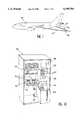
- FIGS. 1 and 2illustrate the flight refuelling operation of one or more aircraft.
- FIGS. 3 to 10illustrate different characteristics of the system according to the invention.
- the flight refuelling procedureas illustrated in FIGS. 1 and 2, is almost as old as military aircraft themselves.
- the means usedhave advanced in proportion to general technological advances.
- the present inventionmust be looked upon as the final improvement stage provided by military aeronautics.
- the refuelling aircraft 10is provided with a boom 12, which is a telescopic, rigid tubular mechanism carrying mobile surfaces 13 permitting the "control" thereof.
- the refuelled aircraft 9In its upper, front part the refuelled aircraft 9 then has a receptacle 14 which can be likened to a funnel and into which can be fitted the telescopic tube of said mechanism 12 integral with the refuelling aircraft.
- the refuelling aircraftIn the second procedure, the refuelling aircraft, with the aid of a pod or winch, unwinds and allows to trail behind a flexible tube 15 at the end 16 (provided with a basket member) of which is connected the refuelled aircraft, which then carries for this purpose a refuelling "probe" 17 located at the front of the aircraft.
- This probecan also be associated with a telescopic tube.
- the tubeis provided with an adaptor, so as to permit the fixing thereto of a basket member, depending on the fuel flow rate.
- the system according to the inventionenables the two procedures to cohabit on the same refuelling aircraft.
- the interconnection of the flight refuelling system and aircraft systemsenables the operator responsible for the refuelling to participate in the crew activities outside the period of said refuelling operations.
- FIG. 2illustrates the possibility of the flight refuelling of aircraft 11,9 by the same refuelling aircraft 10.
- the refuelling aircraft 10e.g. comprises a flexible tube 15 at the end of each wing and a telescopic tube 12 beneath the fuselage.
- the system according to the inventionhas at least one camera positioned below the aircraft fuselage.
- a refuelling aircraft 10 of the Airbus A310-300 or A300-600 type four camerasthree at the landing gear in order to cover the rear area of the aircraft and one (or two for technical and redundancy reasons) beneath the telescopic tube so as to display the relative positions of the end of the telescopic tube and the receptacle of the refuelling aircraft.
- the system according to the inventionuses at least one multimode display, as well as at least one multifunction equipment located in a working station available to the operator responsible for the checking and control of the flight refuelling.
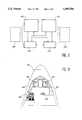
- FIG. 3shows a multimode display 20 able to display on the same screen an image from a camera and/or a symbology.
- the image of the refuelled aircraft 9 by a telescopic tube-type device 12is associated with fuel data 21.
- the different indications XXrepresent the available fuel quantities either in total or for each of the tanks shown diagrammatically at the bottom of the screen. Two other symbology examples are given in FIGS. 4 and 5.
- the image supplied by a camera connected to said screencan be superimposed on said symbologies.
- FIG. 4illustrates the symbology associated with the fuel of the aircraft, i.e.:
- the fuelflows to aircraft refuelled by pods, the winch 30 or the telescopic tube 31 of the refuelling aircraft,
- the fuelflows to the refuelling aircraft by the probe or receptacle,
- the letters XXrepresent the fuel quantities (or flow rates when placed in brackets). This image is evolutive and a function of the device or devices installed on the aircraft.
- the second example shown in FIG. 5illustrates an image associated with the control of the telescopic tube, i.e. relative position of the tube 36 and receptacle 37, azimuth 38, elevation 39 and tube-receptacle distance information 40, tendencies with respect to the control objectives, control state information and messages.
- the symbols in the drawinghave the following meaning:
- This principlecan be applied to a device of the winch type, if the latter is equipped with mobile surfaces located on the basket member.
- FIG. 7shows a second equipment of the system according to the invention in the form of a multifunction equipment 45 having a screen 46 and a control keyboard 47.
- FIG. 6show a possible illumination at night of the refuelling aircraft 10.
- FIG. 7then indicates on the multifunction display, a possibility of operating the corresponding lamps either one by one, or simultaneously.
- the monitoring type for the multimode displaymainly of the refuelled aircraft (camera image), the fuel system (symbology) of the refuelling aircraft, etc.
- the multifunction equipmenti.e. winding up or unwinding of the nacelle hose
- the tasks of a monitoring typeare also supplemented by messages supplied on the screens.
- the aforementioned meansare duplicated so as to enable the operator to prepare the following sequence or perform his mission in the case of a failure of one of the preceding equipments, so that the duplicated architecture of FIG. 8 is chosen.
- the possibility of adding e.g. in the development phase a third multimode displaydoes not interfere with the above principles.
- This architecturebased on two multimode displays 50,51 and two multifunction equipments 52,53 permits:
- a loadermagnetic or optical reader
- checklistlist of actions to be performed without malfuntion
- miscellaneousinformation returned to flight crew.
- the associated computers and the corresponding processing operationscan be integrated into multifunction equipment blocks 52,53, display 50,51 or external means (not shown in FIG. 8 in this case).
- FIGS. 9 and 10use in exemplified manner Airbus A310-300 or A300-600-type aircraft with a possible location of the working station in the cockpit and the installation associated with the equipment in question including supplementary equipment which, although not part of the architecture in question, still constitutes a complement for rapid access and/or safety reasons (e.g. disconnection of the telescopic tube, cutting the nacelle hoses, etc.) or which are indispensable to the environment of the operator (e.g. oxygen in the case of depressurization, radio link with the flight crew, etc.).
- supplementary equipmente.g. disconnection of the telescopic tube, cutting the nacelle hoses, etc.
- oxygene.g. oxygen in the case of depressurization, radio link with the flight crew, etc.
- FIG. 9shows:
- FIG. 10shows the working station 65 for the fuel operator and which inter alia incorporates:
Landscapes
- Engineering & Computer Science (AREA)
- Aviation & Aerospace Engineering (AREA)
- Loading And Unloading Of Fuel Tanks Or Ships (AREA)
- Monitoring And Testing Of Nuclear Reactors (AREA)
Abstract
Description
Claims (8)
Applications Claiming Priority (2)
| Application Number | Priority Date | Filing Date | Title |
|---|---|---|---|
| FR9305718AFR2705082B1 (en) | 1993-05-12 | 1993-05-12 | In-flight refueling system. |
| FR9305718 | 1993-05-12 |
Publications (1)
| Publication Number | Publication Date |
|---|---|
| US5499784Atrue US5499784A (en) | 1996-03-19 |
Family
ID=9447054
Family Applications (1)
| Application Number | Title | Priority Date | Filing Date |
|---|---|---|---|
| US08/241,018Expired - LifetimeUS5499784A (en) | 1993-05-12 | 1994-05-11 | Flight refuelling system |
Country Status (2)
| Country | Link |
|---|---|
| US (1) | US5499784A (en) |
| FR (1) | FR2705082B1 (en) |
Cited By (63)
| Publication number | Priority date | Publication date | Assignee | Title |
|---|---|---|---|---|
| US6324295B1 (en)* | 1996-05-10 | 2001-11-27 | Sextant Avionique | Guiding method and device for in-flight-refuelling line |
| US6604711B1 (en)* | 2000-11-20 | 2003-08-12 | Sargent Fletcher, Inc. | Autonomous system for the aerial refueling or decontamination of unmanned airborne vehicles |
| WO2003084232A1 (en)* | 2002-03-28 | 2003-10-09 | Bendix Commercial Vehicle Systems Llc | An integrated video/data information system and method for application to commercial vehicles to enhance driver awareness |
| US6644594B1 (en)* | 2002-11-12 | 2003-11-11 | The United States Of America As Represented By The Secretary Of The Air Force | Flight refueling guide |
| US20030209633A1 (en)* | 2002-05-10 | 2003-11-13 | Thal German Von | Distance measuring using passive visual means |
| US20030210807A1 (en)* | 2002-05-09 | 2003-11-13 | Satoshi Sato | Monitoring device, monitoring method and program for monitoring |
| US6651933B1 (en) | 2002-05-01 | 2003-11-25 | The Boeing Company | Boom load alleviation using visual means |
| US20040101167A1 (en)* | 2002-11-22 | 2004-05-27 | Thal German Von | Method and apparatus for covertly determining the rate of relative motion between two objects |
| US20040182966A1 (en)* | 2001-06-08 | 2004-09-23 | Catherine Schneider | Method for managing in-flight refuelling of a fleet of aircraft |
| FR2861198A1 (en)* | 2003-10-20 | 2005-04-22 | Airbus France | Fuel quantity transfer optimization process for aircraft, involves determining fuel quantity to be transferred at flight point from quantities that remain aboard aircraft at point and that allow aircraft to fly to another point |
| US6966525B1 (en)* | 2004-06-28 | 2005-11-22 | The Boeing Company | In-flight refueling system, alignment system, and method for automatic alignment and engagement of an in-flight refueling boom |
| US20060192053A1 (en)* | 2005-02-25 | 2006-08-31 | Crangle Gage B | Systems and methods for controlling flexible communication links used for aircraft refueling |
| EP1700784A1 (en)* | 2005-03-11 | 2006-09-13 | The Boeing Company | Refueling booms with multiple couplings and associated methods and systems |
| US20060208132A1 (en)* | 2004-07-12 | 2006-09-21 | Jones Philip E | Autonomous in-flight refueling system |
| US20060226293A1 (en)* | 2005-02-25 | 2006-10-12 | Smiths Aerospace Llc | Optical tracking system for refueling |
| US20070023575A1 (en)* | 2005-07-29 | 2007-02-01 | Von Thal German | Vision system and method incorporating graphics symbology for use in a tanker refueling system |
| US20070023574A1 (en)* | 2005-07-29 | 2007-02-01 | Von Thal German | Graphical symbology apparatus for use in an airborne refueling system |
| US20070040065A1 (en)* | 2005-08-19 | 2007-02-22 | Von Thal German | Flexible refueling boom extendable tube |
| US20070069071A1 (en)* | 2005-06-08 | 2007-03-29 | The Boeing Company | Systems and methods for providing back-up hydraulic power for aircraft, including tanker aircraft |
| US20070102583A1 (en)* | 2005-10-26 | 2007-05-10 | Cutler Theron L | Systems and methods for reducing surge loads in hose assemblies, including aircraft refueling hose assemblies |
| US20070257154A1 (en)* | 2006-05-05 | 2007-11-08 | The Boeing Company | In-flight refueling lightning protection system |
| US20080054124A1 (en)* | 2005-06-20 | 2008-03-06 | The Boeing Company | Controllable refueling drogues and associated systems and methods |
| KR100843171B1 (en)* | 2002-09-12 | 2008-07-02 | 한국항공우주산업 주식회사 | Air refueling tank for aircraft |
| US20080234884A1 (en)* | 2007-03-21 | 2008-09-25 | Von Thal German | System and method for facilitating aerial refueling |
| US20080251643A1 (en)* | 2007-04-11 | 2008-10-16 | Johnston Joel J | Methods and apparatus for resisting torsional loads in aerial refueling booms |
| US20080302916A1 (en)* | 2005-03-24 | 2008-12-11 | Speer Thomas E | Systems and methods for automatically and semiautomatically controlling aircraft refueling |
| US7533850B2 (en) | 2005-06-09 | 2009-05-19 | The Boeing Company | Fittings with redundant seals for aircraft fuel lines, fuel tanks, and other systems |
| US20090292406A1 (en)* | 2008-05-22 | 2009-11-26 | Eads Construcciones Aeronauticas, S.A., | Methods and systems for reducing the phenomenon of structural coupling in the control system of an in-flight refuelling boom |
| US20100024189A1 (en)* | 2005-06-09 | 2010-02-04 | The Boeing Company | Systems and Methods for Distributing Loads from Fluid Conduits, Including Aircraft Fuel Conduits |
| US7665479B2 (en) | 2005-06-10 | 2010-02-23 | The Boeing Company | Aerial refueling system |
| US20100213318A1 (en)* | 2006-11-13 | 2010-08-26 | Steven Martin Hudson | Conductive bodies |
| US20100256838A1 (en)* | 2009-04-03 | 2010-10-07 | The Boeing Company | Multi-mission remote aerial refueling operator system |
| US20110049288A1 (en)* | 2008-08-21 | 2011-03-03 | Satoshi Suzuki | Unmanned aircraft system and operation method thereof |
| US20110147528A1 (en)* | 2009-12-18 | 2011-06-23 | Eads Construcciones Aeronauticas, S.A. | Method and system for enhanced vision in aerial refueling operations |
| US7980512B1 (en)* | 2008-06-13 | 2011-07-19 | The Boeing Company | System and method for displaying aerial refueling symbology |
| US20110253894A1 (en)* | 2010-04-20 | 2011-10-20 | Eads Construcciones Aeronauticas, S.A. | System for night vision from distant observation places |
| WO2013102903A2 (en) | 2012-01-04 | 2013-07-11 | Israel Aerospace Industries Ltd. | Devices, systems and methods for refueling air vehicles |
| US8596580B1 (en)* | 2010-09-27 | 2013-12-03 | The Boeing Company | Advanced performance refueling boom |
| US20140175221A1 (en)* | 2012-12-21 | 2014-06-26 | Airbus Sas | Aircraft comprising a cockpit delocalized outside an upper part of the nose |
| US20140319279A1 (en)* | 2013-01-14 | 2014-10-30 | The Boeing Company | Aircraft refueling system and method of refueling an aircraft |
| GB2514430A (en)* | 2013-05-21 | 2014-11-26 | Singapore Tech Aerospace Ltd | A system and method for transferring fuel in flight from a tanker aircraft to multiple receiver aircraft |
| CN104802992A (en)* | 2015-03-17 | 2015-07-29 | 张峰 | Suspension drag mount type flying aircraft carrier |
| US20150217857A1 (en)* | 2014-02-03 | 2015-08-06 | Airbus Operations (S.A.S.) | Methods, systems and computer readable media for managing aircraft systems |
| US9150310B1 (en)* | 2010-09-10 | 2015-10-06 | The Boeing Company | Methods and systems for directing remote aerial refueling operations |
| US20160001891A1 (en)* | 2006-03-02 | 2016-01-07 | The Boeing Company | System and Method for Identifying a Receiving Aircraft During Airborne Fueling |
| US9399525B2 (en) | 2014-02-03 | 2016-07-26 | Airbus Operations (S.A.S.) | Method, systems, and computer readable media for troubleshooting an aircraft system during system failure |
| USD765688S1 (en) | 2014-02-03 | 2016-09-06 | Airbus Operations (S.A.S.) | Display screen or portion thereof with graphical user interface |
| USD766280S1 (en) | 2014-02-03 | 2016-09-13 | Airbus Operations (S.A.S.) | Display screen or portion thereof with graphical user interface |
| USD766281S1 (en) | 2014-02-03 | 2016-09-13 | Airbus Operations (S.A.S.) | Display screen or portion thereof with graphical user interface |
| USD766918S1 (en) | 2014-02-03 | 2016-09-20 | Airbus Operations (S.A.S.) | Display screen of portion thereof with changeable graphical user interface |
| US9457892B2 (en) | 2014-02-03 | 2016-10-04 | Airbus Operations (S.A.S.) | Management interfaces for aircraft systems |
| CN108369423A (en)* | 2015-10-09 | 2018-08-03 | 狄芬萨工程国际有限公司 | System for positioning the position of winged yardarm portion, oiling vessel port and fuel charger |
| WO2018235071A1 (en) | 2017-06-18 | 2018-12-27 | Israel Aerospace Industries Ltd. | SYSTEM AND METHOD FOR FUEL REFUELING OF AERIAL VEHICLES |
| US10435288B2 (en)* | 2016-04-18 | 2019-10-08 | Guangzhou Xaircraft Technology Co., Ltd. | Liquid volume transfer system, liquid infusion device, unmanned aerial vehicle and liquid container |
| US20210163148A1 (en)* | 2016-08-20 | 2021-06-03 | Modern Technology Solutions, Inc. | Tanker boom control |
| US20220212811A1 (en)* | 2021-01-05 | 2022-07-07 | The Boeing Company | Fuel receptacle and boom tip position and pose estimation for aerial refueling |
| US11465768B2 (en) | 2017-07-10 | 2022-10-11 | Israel Aerospace Industries Ltd. | Refueling device |
| US11599323B2 (en) | 2020-09-28 | 2023-03-07 | Rockwell Collins, Inc. | Touchscreen boom pod |
| US11628737B2 (en)* | 2020-02-03 | 2023-04-18 | Textron Innovations Inc. | In-flight recharging of aerial electric vehicles |
| US20230202670A1 (en)* | 2016-08-20 | 2023-06-29 | Modern Technology Solutions, Inc. | Vehicle refueling and recharging |
| USD1006822S1 (en) | 2020-10-30 | 2023-12-05 | Rockwell Collins, Inc. | Touchscreen display boom graphical user interface |
| US12106516B2 (en) | 2022-01-05 | 2024-10-01 | The Boeing Company | Pose estimation refinement for aerial refueling |
| US12148184B2 (en) | 2022-01-05 | 2024-11-19 | The Boeing Company | Temporally consistent position estimation refinement for aerial refueling |
Families Citing this family (3)
| Publication number | Priority date | Publication date | Assignee | Title |
|---|---|---|---|---|
| US7147186B2 (en)* | 2004-11-18 | 2006-12-12 | The Boeing Company | Interoperable aerial refueling apparatus and methods |
| FR2985069B1 (en)* | 2011-12-23 | 2013-12-20 | Thales Sa | SYSTEM FOR MANAGING THE SYSTEMS OF AN AIRCRAFT |
| US10882635B2 (en) | 2018-05-09 | 2021-01-05 | The Boeing Company | Aiding maneuvering of obscured objects |
Citations (15)
| Publication number | Priority date | Publication date | Assignee | Title |
|---|---|---|---|---|
| US3917196A (en)* | 1974-02-11 | 1975-11-04 | Boeing Co | Apparatus suitable for use in orienting aircraft flight for refueling or other purposes |
| US4025193A (en)* | 1974-02-11 | 1977-05-24 | The Boeing Company | Apparatus suitable for use in orienting aircraft in-flight for refueling or other purposes |
| US4158885A (en)* | 1977-11-09 | 1979-06-19 | The Boeing Company | Guidance-light display apparatus and method for in-flight link-up of two aircraft |
| US4160534A (en)* | 1977-12-30 | 1979-07-10 | The Boeing Company | Operating station for aircraft refueling boom |
| US4247843A (en)* | 1978-08-23 | 1981-01-27 | Sperry Corporation | Aircraft flight instrument display system |
| US4298176A (en)* | 1979-03-01 | 1981-11-03 | Mcdonnell Douglas Corporation | Remote refueling station |
| US4398685A (en)* | 1981-03-11 | 1983-08-16 | The United States Of America As Represented By The Secretary Of The Air Force | Aerial day/night refueling stations |
| FR2569652A1 (en)* | 1984-09-04 | 1986-03-07 | Messerschmitt Boelkow Blohm | Tanker aircraft in-flight fuelling gear |
| FR2572706A1 (en)* | 1984-11-08 | 1986-05-09 | Messerschmitt Boelkow Blohm | Airborne fighter-tanker re-fuelling system |
| USH297H (en)* | 1985-08-12 | 1987-07-07 | The United States Of America As Represented By The Secretary Of The Air Force | Robotic refueling system for tactical and strategic aircraft |
| WO1991006471A1 (en)* | 1989-10-27 | 1991-05-16 | Gec-Marconi Limited | Refueling apparatus |
| US5036315A (en)* | 1988-09-06 | 1991-07-30 | Spectragraphics, Inc. | Simultaneous display of interleaved windowed video information from multiple asynchronous computers on a single video monitor |
| US5157451A (en)* | 1991-04-01 | 1992-10-20 | John Taboada | Laser imaging and ranging system using two cameras |
| WO1993007055A1 (en)* | 1991-10-02 | 1993-04-15 | Enig Associates, Inc. | Controllable hose-and-drogue in-flight refueling system |
| US5351129A (en)* | 1992-03-24 | 1994-09-27 | Rgb Technology D/B/A Rgb Spectrum | Video multiplexor-encoder and decoder-converter |
- 1993
- 1993-05-12FRFR9305718Apatent/FR2705082B1/ennot_activeExpired - Lifetime
- 1994
- 1994-05-11USUS08/241,018patent/US5499784A/ennot_activeExpired - Lifetime
Patent Citations (15)
| Publication number | Priority date | Publication date | Assignee | Title |
|---|---|---|---|---|
| US3917196A (en)* | 1974-02-11 | 1975-11-04 | Boeing Co | Apparatus suitable for use in orienting aircraft flight for refueling or other purposes |
| US4025193A (en)* | 1974-02-11 | 1977-05-24 | The Boeing Company | Apparatus suitable for use in orienting aircraft in-flight for refueling or other purposes |
| US4158885A (en)* | 1977-11-09 | 1979-06-19 | The Boeing Company | Guidance-light display apparatus and method for in-flight link-up of two aircraft |
| US4160534A (en)* | 1977-12-30 | 1979-07-10 | The Boeing Company | Operating station for aircraft refueling boom |
| US4247843A (en)* | 1978-08-23 | 1981-01-27 | Sperry Corporation | Aircraft flight instrument display system |
| US4298176A (en)* | 1979-03-01 | 1981-11-03 | Mcdonnell Douglas Corporation | Remote refueling station |
| US4398685A (en)* | 1981-03-11 | 1983-08-16 | The United States Of America As Represented By The Secretary Of The Air Force | Aerial day/night refueling stations |
| FR2569652A1 (en)* | 1984-09-04 | 1986-03-07 | Messerschmitt Boelkow Blohm | Tanker aircraft in-flight fuelling gear |
| FR2572706A1 (en)* | 1984-11-08 | 1986-05-09 | Messerschmitt Boelkow Blohm | Airborne fighter-tanker re-fuelling system |
| USH297H (en)* | 1985-08-12 | 1987-07-07 | The United States Of America As Represented By The Secretary Of The Air Force | Robotic refueling system for tactical and strategic aircraft |
| US5036315A (en)* | 1988-09-06 | 1991-07-30 | Spectragraphics, Inc. | Simultaneous display of interleaved windowed video information from multiple asynchronous computers on a single video monitor |
| WO1991006471A1 (en)* | 1989-10-27 | 1991-05-16 | Gec-Marconi Limited | Refueling apparatus |
| US5157451A (en)* | 1991-04-01 | 1992-10-20 | John Taboada | Laser imaging and ranging system using two cameras |
| WO1993007055A1 (en)* | 1991-10-02 | 1993-04-15 | Enig Associates, Inc. | Controllable hose-and-drogue in-flight refueling system |
| US5351129A (en)* | 1992-03-24 | 1994-09-27 | Rgb Technology D/B/A Rgb Spectrum | Video multiplexor-encoder and decoder-converter |
Cited By (120)
| Publication number | Priority date | Publication date | Assignee | Title |
|---|---|---|---|---|
| US6324295B1 (en)* | 1996-05-10 | 2001-11-27 | Sextant Avionique | Guiding method and device for in-flight-refuelling line |
| US6604711B1 (en)* | 2000-11-20 | 2003-08-12 | Sargent Fletcher, Inc. | Autonomous system for the aerial refueling or decontamination of unmanned airborne vehicles |
| US20040182966A1 (en)* | 2001-06-08 | 2004-09-23 | Catherine Schneider | Method for managing in-flight refuelling of a fleet of aircraft |
| US6832743B2 (en)* | 2001-06-08 | 2004-12-21 | Thales | Method for managing in-flight refuelling of a fleet of aircraft |
| WO2003084232A1 (en)* | 2002-03-28 | 2003-10-09 | Bendix Commercial Vehicle Systems Llc | An integrated video/data information system and method for application to commercial vehicles to enhance driver awareness |
| US20030222982A1 (en)* | 2002-03-28 | 2003-12-04 | Hamdan Majil M. | Integrated video/data information system and method for application to commercial vehicles to enhance driver awareness |
| US6651933B1 (en) | 2002-05-01 | 2003-11-25 | The Boeing Company | Boom load alleviation using visual means |
| US7266220B2 (en)* | 2002-05-09 | 2007-09-04 | Matsushita Electric Industrial Co., Ltd. | Monitoring device, monitoring method and program for monitoring |
| US20030210807A1 (en)* | 2002-05-09 | 2003-11-13 | Satoshi Sato | Monitoring device, monitoring method and program for monitoring |
| US6752357B2 (en)* | 2002-05-10 | 2004-06-22 | The Boeing Company | Distance measuring using passive visual means |
| US20030209633A1 (en)* | 2002-05-10 | 2003-11-13 | Thal German Von | Distance measuring using passive visual means |
| KR100843171B1 (en)* | 2002-09-12 | 2008-07-02 | 한국항공우주산업 주식회사 | Air refueling tank for aircraft |
| US6644594B1 (en)* | 2002-11-12 | 2003-11-11 | The United States Of America As Represented By The Secretary Of The Air Force | Flight refueling guide |
| US7171028B2 (en)* | 2002-11-22 | 2007-01-30 | The Boeing Company | Method and apparatus for covertly determining the rate of relative motion between two objects |
| US20040101167A1 (en)* | 2002-11-22 | 2004-05-27 | Thal German Von | Method and apparatus for covertly determining the rate of relative motion between two objects |
| FR2861198A1 (en)* | 2003-10-20 | 2005-04-22 | Airbus France | Fuel quantity transfer optimization process for aircraft, involves determining fuel quantity to be transferred at flight point from quantities that remain aboard aircraft at point and that allow aircraft to fly to another point |
| EP1527998A1 (en)* | 2003-10-20 | 2005-05-04 | Airbus France | Method and device to optimise the fuel quantity to be transferred to an aircraft during in-flight refuelling |
| US20050116109A1 (en)* | 2003-10-20 | 2005-06-02 | Airbus France | Procedure and device for optimizing the quantity of fuel transferred on an aircraft during at least one in-fligh fuel transfer |
| US8596579B2 (en)* | 2003-10-20 | 2013-12-03 | Airbus Operations Sas | Procedure and device for optimizing the quantity of fuel transferred on an aircraft during at least one in-fligh fuel transfer |
| US6966525B1 (en)* | 2004-06-28 | 2005-11-22 | The Boeing Company | In-flight refueling system, alignment system, and method for automatic alignment and engagement of an in-flight refueling boom |
| WO2006091217A1 (en)* | 2004-06-28 | 2006-08-31 | The Boeing Company | In-flight refueling system, alignment system, and method for automatic alignment and engagement of an in-flight refueling boom |
| US7562847B2 (en)* | 2004-07-12 | 2009-07-21 | Parker-Hannifin Corporation | Autonomous in-flight refueling system |
| US20060208132A1 (en)* | 2004-07-12 | 2006-09-21 | Jones Philip E | Autonomous in-flight refueling system |
| US8104716B2 (en) | 2005-02-25 | 2012-01-31 | Ge Aviation Systems Llc | Optical tracking system for airborne objects |
| US20060226293A1 (en)* | 2005-02-25 | 2006-10-12 | Smiths Aerospace Llc | Optical tracking system for refueling |
| US20080075467A1 (en)* | 2005-02-25 | 2008-03-27 | Smiths Aerospace Llc | Optical tracking system for airborne objects |
| US20100163679A1 (en)* | 2005-02-25 | 2010-07-01 | Mickley Joseph G | Optical tracking system for airborne objects |
| US7686252B2 (en)* | 2005-02-25 | 2010-03-30 | Smiths Aerospace, Llc | Optical tracking system for airborne objects |
| US7681839B2 (en)* | 2005-02-25 | 2010-03-23 | Smiths Aerospace Llc | Optical tracking system for refueling |
| US20080067290A1 (en)* | 2005-02-25 | 2008-03-20 | Mickley Joseph G | Optical tracking system for airborne objects |
| US7309047B2 (en)* | 2005-02-25 | 2007-12-18 | The Boeing Company | Systems and methods for controlling flexible communication links used for aircraft refueling |
| US20060192053A1 (en)* | 2005-02-25 | 2006-08-31 | Crangle Gage B | Systems and methods for controlling flexible communication links used for aircraft refueling |
| EP1700784A1 (en)* | 2005-03-11 | 2006-09-13 | The Boeing Company | Refueling booms with multiple couplings and associated methods and systems |
| US7469863B1 (en)* | 2005-03-24 | 2008-12-30 | The Boeing Company | Systems and methods for automatically and semiautomatically controlling aircraft refueling |
| US20080302916A1 (en)* | 2005-03-24 | 2008-12-11 | Speer Thomas E | Systems and methods for automatically and semiautomatically controlling aircraft refueling |
| US7637458B2 (en) | 2005-06-08 | 2009-12-29 | The Boeing Company | Systems and methods for providing back-up hydraulic power for aircraft, including tanker aircraft |
| US20070069071A1 (en)* | 2005-06-08 | 2007-03-29 | The Boeing Company | Systems and methods for providing back-up hydraulic power for aircraft, including tanker aircraft |
| US20100024189A1 (en)* | 2005-06-09 | 2010-02-04 | The Boeing Company | Systems and Methods for Distributing Loads from Fluid Conduits, Including Aircraft Fuel Conduits |
| US7922122B2 (en) | 2005-06-09 | 2011-04-12 | The Boeing Company | Systems and methods for distributing loads from fluid conduits, including aircraft fuel conduits |
| US8356842B2 (en) | 2005-06-09 | 2013-01-22 | Carns James A | Fittings with redundant seals for aircraft fuel lines, fuel tanks, and other systems |
| US7533850B2 (en) | 2005-06-09 | 2009-05-19 | The Boeing Company | Fittings with redundant seals for aircraft fuel lines, fuel tanks, and other systems |
| US7665479B2 (en) | 2005-06-10 | 2010-02-23 | The Boeing Company | Aerial refueling system |
| US20080054124A1 (en)* | 2005-06-20 | 2008-03-06 | The Boeing Company | Controllable refueling drogues and associated systems and methods |
| US7887010B2 (en) | 2005-06-20 | 2011-02-15 | The Boeing Company | Controllable refueling drogues and associated systems and methods |
| US20070023575A1 (en)* | 2005-07-29 | 2007-02-01 | Von Thal German | Vision system and method incorporating graphics symbology for use in a tanker refueling system |
| US20070023574A1 (en)* | 2005-07-29 | 2007-02-01 | Von Thal German | Graphical symbology apparatus for use in an airborne refueling system |
| EP1747991A3 (en)* | 2005-07-29 | 2007-12-05 | The Boeing Company | Graphical symbology apparatus for use in an airborne refueling system |
| EP1747992A3 (en)* | 2005-07-29 | 2007-12-19 | The Boeing Company | Vision system and method incorporating graphics symbology for use in a tanker refueling system |
| US7298291B2 (en)* | 2005-07-29 | 2007-11-20 | The Boeing Company | Graphical symbology apparatus for use in an airborne refueling system |
| US7309048B2 (en)* | 2005-07-29 | 2007-12-18 | The Boeing Company | Vision system and method incorporating graphics symbology for use in a tanker refueling system |
| US20070040065A1 (en)* | 2005-08-19 | 2007-02-22 | Von Thal German | Flexible refueling boom extendable tube |
| US20070102583A1 (en)* | 2005-10-26 | 2007-05-10 | Cutler Theron L | Systems and methods for reducing surge loads in hose assemblies, including aircraft refueling hose assemblies |
| US20160001891A1 (en)* | 2006-03-02 | 2016-01-07 | The Boeing Company | System and Method for Identifying a Receiving Aircraft During Airborne Fueling |
| US10035606B2 (en)* | 2006-03-02 | 2018-07-31 | The Boeing Company | System and method for identifying a receiving aircraft during airborne fueling |
| US7597288B2 (en)* | 2006-05-05 | 2009-10-06 | The Boeing Company | In-flight refueling lightning protection system |
| US20070257154A1 (en)* | 2006-05-05 | 2007-11-08 | The Boeing Company | In-flight refueling lightning protection system |
| US20100213318A1 (en)* | 2006-11-13 | 2010-08-26 | Steven Martin Hudson | Conductive bodies |
| US8639395B2 (en)* | 2006-11-13 | 2014-01-28 | Steven Martin Hudson | Conductive bodies |
| US20080234884A1 (en)* | 2007-03-21 | 2008-09-25 | Von Thal German | System and method for facilitating aerial refueling |
| US8132759B2 (en) | 2007-03-21 | 2012-03-13 | The Boeing Company | System and method for facilitating aerial refueling |
| US7959110B2 (en) | 2007-04-11 | 2011-06-14 | The Boeing Company | Methods and apparatus for resisting torsional loads in aerial refueling booms |
| US20080251643A1 (en)* | 2007-04-11 | 2008-10-16 | Johnston Joel J | Methods and apparatus for resisting torsional loads in aerial refueling booms |
| US8332081B2 (en)* | 2008-05-22 | 2012-12-11 | Eads Construcciones Aeronauticas, S.A. | Methods and systems for reducing the phenomenon of structural coupling in the control system of an in-flight refuelling boom |
| US20090292406A1 (en)* | 2008-05-22 | 2009-11-26 | Eads Construcciones Aeronauticas, S.A., | Methods and systems for reducing the phenomenon of structural coupling in the control system of an in-flight refuelling boom |
| US20110180666A1 (en)* | 2008-06-13 | 2011-07-28 | The Boeing Company | System and method for displaying aerial refueling symbology |
| US7980512B1 (en)* | 2008-06-13 | 2011-07-19 | The Boeing Company | System and method for displaying aerial refueling symbology |
| US20110049288A1 (en)* | 2008-08-21 | 2011-03-03 | Satoshi Suzuki | Unmanned aircraft system and operation method thereof |
| US8740134B2 (en)* | 2008-08-21 | 2014-06-03 | Mitsubishi Heavy Industries, Ltd. | Unmanned aircraft system and operation method thereof |
| US8370002B2 (en)* | 2009-04-03 | 2013-02-05 | The Boeing Company | Multi-mission remote aerial refueling operator system |
| EP2236421A3 (en)* | 2009-04-03 | 2013-07-03 | The Boeing Company | Multi-mission remote aerial refueling operator system |
| US20100256838A1 (en)* | 2009-04-03 | 2010-10-07 | The Boeing Company | Multi-mission remote aerial refueling operator system |
| US20110147528A1 (en)* | 2009-12-18 | 2011-06-23 | Eads Construcciones Aeronauticas, S.A. | Method and system for enhanced vision in aerial refueling operations |
| US20110253894A1 (en)* | 2010-04-20 | 2011-10-20 | Eads Construcciones Aeronauticas, S.A. | System for night vision from distant observation places |
| US9150310B1 (en)* | 2010-09-10 | 2015-10-06 | The Boeing Company | Methods and systems for directing remote aerial refueling operations |
| US8596580B1 (en)* | 2010-09-27 | 2013-12-03 | The Boeing Company | Advanced performance refueling boom |
| US9457912B2 (en) | 2012-01-04 | 2016-10-04 | Israel Aerospace Industries Ltd. | Systems and methods for air vehicles |
| US9150311B2 (en) | 2012-01-04 | 2015-10-06 | Israel Aerospace Industries Ltd. | Systems and methods for air vehicles |
| US9573696B2 (en) | 2012-01-04 | 2017-02-21 | Israel Aerospace Industries Ltd. | Systems and methods for air vehicles |
| WO2013102903A2 (en) | 2012-01-04 | 2013-07-11 | Israel Aerospace Industries Ltd. | Devices, systems and methods for refueling air vehicles |
| US11180262B2 (en) | 2012-01-04 | 2021-11-23 | Israel Aerospace Industries Ltd. | Devices, systems and methods for refueling air vehicles |
| US11167860B2 (en) | 2012-01-04 | 2021-11-09 | Israel Aerospace Industries Ltd. | Devices, systems and methods for refueling air vehicles |
| US10421556B2 (en) | 2012-01-04 | 2019-09-24 | Israel Aerospace Industries Ltd. | Devices, systems and methods for refueling air vehicles |
| US11834192B2 (en) | 2012-01-04 | 2023-12-05 | Israel Aerospace Industries Ltd. | Devices, systems and methods for refueling air vehicles |
| WO2013102906A2 (en) | 2012-01-04 | 2013-07-11 | Israel Aerospace Industries Ltd. | Devices, systems and methods for refueling air vehicles |
| US10543929B2 (en) | 2012-01-04 | 2020-01-28 | Israel Aerospace Industries Ltd. | Systems and method for air vehicles |
| US10479523B2 (en) | 2012-01-04 | 2019-11-19 | Israel Aerospace Industries Ltd. | Systems and methods for air vehicles |
| US10427801B2 (en) | 2012-01-04 | 2019-10-01 | Israel Aerospace Industries Ltd. | Devices, systems and methods for refueling air vehicles |
| US20140175221A1 (en)* | 2012-12-21 | 2014-06-26 | Airbus Sas | Aircraft comprising a cockpit delocalized outside an upper part of the nose |
| US9789961B2 (en)* | 2012-12-21 | 2017-10-17 | Airbus Sas | Aircraft comprising a cockpit delocalized outside an upper part of the nose |
| US9067689B2 (en)* | 2013-01-14 | 2015-06-30 | The Boeing Company | Aircraft refueling system and method of refueling an aircraft |
| US20140319279A1 (en)* | 2013-01-14 | 2014-10-30 | The Boeing Company | Aircraft refueling system and method of refueling an aircraft |
| GB2514430B (en)* | 2013-05-21 | 2015-04-15 | Singapore Tech Aerospace Ltd | A system and method for transferring fuel in flight from a tanker aircraft to multiple receiver aircraft |
| GB2514430A (en)* | 2013-05-21 | 2014-11-26 | Singapore Tech Aerospace Ltd | A system and method for transferring fuel in flight from a tanker aircraft to multiple receiver aircraft |
| US9315277B2 (en) | 2013-05-21 | 2016-04-19 | Singapore Technologies Aerospace Ltd. | System and method for transferring fuel in flight from a tanker aircraft to multiple receiver aircraft |
| USD766280S1 (en) | 2014-02-03 | 2016-09-13 | Airbus Operations (S.A.S.) | Display screen or portion thereof with graphical user interface |
| USD766281S1 (en) | 2014-02-03 | 2016-09-13 | Airbus Operations (S.A.S.) | Display screen or portion thereof with graphical user interface |
| USD766918S1 (en) | 2014-02-03 | 2016-09-20 | Airbus Operations (S.A.S.) | Display screen of portion thereof with changeable graphical user interface |
| USD765688S1 (en) | 2014-02-03 | 2016-09-06 | Airbus Operations (S.A.S.) | Display screen or portion thereof with graphical user interface |
| US9399525B2 (en) | 2014-02-03 | 2016-07-26 | Airbus Operations (S.A.S.) | Method, systems, and computer readable media for troubleshooting an aircraft system during system failure |
| US9457892B2 (en) | 2014-02-03 | 2016-10-04 | Airbus Operations (S.A.S.) | Management interfaces for aircraft systems |
| US9457893B2 (en)* | 2014-02-03 | 2016-10-04 | Airbus Operations (S.A.S.) | Methods, systems and computer readable media for managing aircraft systems |
| US20150217857A1 (en)* | 2014-02-03 | 2015-08-06 | Airbus Operations (S.A.S.) | Methods, systems and computer readable media for managing aircraft systems |
| CN104802992A (en)* | 2015-03-17 | 2015-07-29 | 张峰 | Suspension drag mount type flying aircraft carrier |
| CN108369423A (en)* | 2015-10-09 | 2018-08-03 | 狄芬萨工程国际有限公司 | System for positioning the position of winged yardarm portion, oiling vessel port and fuel charger |
| US11414207B2 (en)* | 2015-10-09 | 2022-08-16 | Defensya Ingeniería Internacional, S.L. | System for locating the position of the end of the boom, the mouth of the refuelling vessel and the tanker |
| US10435288B2 (en)* | 2016-04-18 | 2019-10-08 | Guangzhou Xaircraft Technology Co., Ltd. | Liquid volume transfer system, liquid infusion device, unmanned aerial vehicle and liquid container |
| US11745894B2 (en)* | 2016-08-20 | 2023-09-05 | Modern Technology Solutions, Inc. | Vehicle refueling and recharging |
| US20230202670A1 (en)* | 2016-08-20 | 2023-06-29 | Modern Technology Solutions, Inc. | Vehicle refueling and recharging |
| US20210163148A1 (en)* | 2016-08-20 | 2021-06-03 | Modern Technology Solutions, Inc. | Tanker boom control |
| US11702220B2 (en)* | 2016-08-20 | 2023-07-18 | Modern Technology Solutions, Inc. | Tanker boom control |
| US11919655B2 (en) | 2017-06-18 | 2024-03-05 | Israel Aerospace Industries Ltd. | System and method for refueling air vehicles |
| WO2018235071A1 (en) | 2017-06-18 | 2018-12-27 | Israel Aerospace Industries Ltd. | SYSTEM AND METHOD FOR FUEL REFUELING OF AERIAL VEHICLES |
| US11465768B2 (en) | 2017-07-10 | 2022-10-11 | Israel Aerospace Industries Ltd. | Refueling device |
| US11628737B2 (en)* | 2020-02-03 | 2023-04-18 | Textron Innovations Inc. | In-flight recharging of aerial electric vehicles |
| US11599323B2 (en) | 2020-09-28 | 2023-03-07 | Rockwell Collins, Inc. | Touchscreen boom pod |
| USD1006822S1 (en) | 2020-10-30 | 2023-12-05 | Rockwell Collins, Inc. | Touchscreen display boom graphical user interface |
| US20220212811A1 (en)* | 2021-01-05 | 2022-07-07 | The Boeing Company | Fuel receptacle and boom tip position and pose estimation for aerial refueling |
| US12139271B2 (en)* | 2021-01-05 | 2024-11-12 | The Boeing Company | Fuel receptacle and boom tip position and pose estimation for aerial refueling |
| US12106516B2 (en) | 2022-01-05 | 2024-10-01 | The Boeing Company | Pose estimation refinement for aerial refueling |
| US12148184B2 (en) | 2022-01-05 | 2024-11-19 | The Boeing Company | Temporally consistent position estimation refinement for aerial refueling |
Also Published As
| Publication number | Publication date |
|---|---|
| FR2705082A1 (en) | 1994-11-18 |
| FR2705082B1 (en) | 1995-08-04 |
Similar Documents
| Publication | Publication Date | Title |
|---|---|---|
| US5499784A (en) | Flight refuelling system | |
| US5739769A (en) | Method of intelligence support of aircraft crew | |
| US20120256768A1 (en) | System and method of using a multi-view display | |
| US10689102B2 (en) | Vertical take-off and landing aircraft | |
| EP2229673B1 (en) | Electro-optical emergency vision apparatus | |
| AU2005338779B8 (en) | Interactive device for legacy cockpit environments | |
| EP2231476A1 (en) | Aircraft command and control system | |
| JP2009500235A (en) | Aircraft management system that also functions as a standby display | |
| US20090198392A1 (en) | Apparatus, program product, and methods for updating data on embedded control systems | |
| WO2015138327A1 (en) | Touch screen instrument panel | |
| US20100019939A1 (en) | Display system for aircraft | |
| WO2015138318A1 (en) | Standby instrument panel for aircraft | |
| US8132759B2 (en) | System and method for facilitating aerial refueling | |
| EP0098090B1 (en) | Console assemblies | |
| JPH06255594A (en) | Pilotless aircraft displaying airframe state | |
| CN112035517A (en) | Portable operation assistance device, system and method for assisting aircraft maneuvering | |
| Burghduff et al. | Man-machine interface and control of the shuttle digital flight system | |
| CN118968852B (en) | Test flight platform suitable for robot pilot | |
| Kim et al. | Analysis of ground control system for a Smart UAV | |
| Hayashi et al. | Effects of the space shuttle cockpit avionics upgrade on crewmember performance and situation awareness | |
| Ryken | Study of modification of a lunar landing research vehicle to a lunar landing training vehicle | |
| US20190112078A1 (en) | Multifaceted instrument console | |
| Stoll | Boeing flight deck design philosophy | |
| CN119597021A (en) | Front and rear cabin cooperative work authority management system and method for aircraft | |
| Roebuck | Space Shuttle Crew Station Requirements Past and Future |
Legal Events
| Date | Code | Title | Description |
|---|---|---|---|
| AS | Assignment | Owner name:AEROSPATIALE SOCIETE NATIONALE INDUSTRIELLE, FRANC Free format text:ASSIGNMENT OF ASSIGNORS INTEREST;ASSIGNORS:CRABERE, HENRI;MITONNEAU, GILBERT;MAURY,JULIEN;REEL/FRAME:007001/0440 Effective date:19940428 | |
| STCF | Information on status: patent grant | Free format text:PATENTED CASE | |
| FEPP | Fee payment procedure | Free format text:PAYOR NUMBER ASSIGNED (ORIGINAL EVENT CODE: ASPN); ENTITY STATUS OF PATENT OWNER: LARGE ENTITY | |
| FPAY | Fee payment | Year of fee payment:4 | |
| FPAY | Fee payment | Year of fee payment:8 | |
| FEPP | Fee payment procedure | Free format text:PAYER NUMBER DE-ASSIGNED (ORIGINAL EVENT CODE: RMPN); ENTITY STATUS OF PATENT OWNER: LARGE ENTITY Free format text:PAYOR NUMBER ASSIGNED (ORIGINAL EVENT CODE: ASPN); ENTITY STATUS OF PATENT OWNER: LARGE ENTITY | |
| FPAY | Fee payment | Year of fee payment:12 | |
| AS | Assignment | Owner name:AIRBUS OPERATIONS SAS, FRANCE Free format text:MERGER;ASSIGNOR:AIRBUS FRANCE;REEL/FRAME:026298/0269 Effective date:20090630 |