US5499542A - Diametral force sensor - Google Patents
Diametral force sensorDownload PDFInfo
- Publication number
- US5499542A US5499542AUS08/231,087US23108794AUS5499542AUS 5499542 AUS5499542 AUS 5499542AUS 23108794 AUS23108794 AUS 23108794AUS 5499542 AUS5499542 AUS 5499542A
- Authority
- US
- United States
- Prior art keywords
- valve stem
- cylindrical member
- load cell
- jaw member
- diametral
- Prior art date
- Legal status (The legal status is an assumption and is not a legal conclusion. Google has not performed a legal analysis and makes no representation as to the accuracy of the status listed.)
- Expired - Lifetime
Links
Images

Classifications
- G—PHYSICS
- G01—MEASURING; TESTING
- G01L—MEASURING FORCE, STRESS, TORQUE, WORK, MECHANICAL POWER, MECHANICAL EFFICIENCY, OR FLUID PRESSURE
- G01L5/00—Apparatus for, or methods of, measuring force, work, mechanical power, or torque, specially adapted for specific purposes
- G01L5/0061—Force sensors associated with industrial machines or actuators
- F—MECHANICAL ENGINEERING; LIGHTING; HEATING; WEAPONS; BLASTING
- F16—ENGINEERING ELEMENTS AND UNITS; GENERAL MEASURES FOR PRODUCING AND MAINTAINING EFFECTIVE FUNCTIONING OF MACHINES OR INSTALLATIONS; THERMAL INSULATION IN GENERAL
- F16K—VALVES; TAPS; COCKS; ACTUATING-FLOATS; DEVICES FOR VENTING OR AERATING
- F16K37/00—Special means in or on valves or other cut-off apparatus for indicating or recording operation thereof, or for enabling an alarm to be given
- F16K37/0075—For recording or indicating the functioning of a valve in combination with test equipment
- F16K37/0083—For recording or indicating the functioning of a valve in combination with test equipment by measuring valve parameters
Definitions
- This inventionrelates to an improved device for measuring diametral changes in a substantially cylindrical member. It relates particularly to a device for measuring slight diametral changes in a substantially cylindrical member, such as a valve stem, that can be used for determining the axial loading on the substantially cylindrical member.
- Motor operated valvesare comprised generally of an electric motor driven valve actuator that is connected to a valve stem and a valve yoke that partially surrounds the valve stem. Rotation of a nut attached to the valve stem by the valve actuator will move a valve plug into a closed, open or intermediate position with respect to a valve seat in the body of the valve.
- a device for determining the diametral changes in a cylindrical member produced by axial loads imposed on the cylindrical membercomprising a clamp assembly having a first jaw member and a second jaw member which are rigidly connected to each other on opposite sides of the cylindrical member.
- the first jaw memberhas a substantially V-shaped recess adapted to engage two peripheral portions of the cylindrical member.
- the second jaw memberhas a flexure with a contact surface contacting a peripheral portion of the cylindrical member and a projection extending away from the contact surface to provide the transmittal of compressive forces representative of diametral changes in the cylindrical member against a compression load cell contained within the second jaw member.
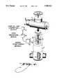
- FIG. 1is an isometric view of a typical motor operated valve assembly, partly in section, to illustrate the installation of the diametral force sensor of this invention on the cylindrical valve stem of the valve assembly.
- FIG. 2is a top view, partly in section, illustrating the preferred embodiment of the diametral force sensor of this invention mounted on a cylindrical valve stem.
- FIG. 3is an elevational view illustrating the preferred embodiment of the diametral force sensor of this invention mounted on a cylindrical valve stem.
- FIG. 1is an isometric view of a typical motor operated valve assembly 1, partly in section, to illustrate the installation of the diametral force sensor 2 of this invention on the cylindrical valve stem 3 of the valve assembly 1.
- the valve assembly 1generally is comprised of a valve body 4 which contains a valve plug or gate 5, operated to a closed, open or intermediate position with respect to a valve seat by the valve stem 3.
- the valve stem 3is partially enclosed by a valve yoke 6 which supports a valve actuator 7 operated by an electric motor 8.
- the diametral force sensor 2 of this inventionis clamped around the valve stem 3.
- the diametral force sensor 2has an electrical cable 9 leading from the diametral force sensor 2 to an electrical signal conditioning module 10, a data recording device 11, such as a computer disk, and a computing and display device 12, such as a personal computer.
- the preferred embodiment of the diametral force sensor 2 of this inventionis a clamp assembly comprised of a first jaw member 13 and a second jaw member 14 rigidly connected to each other and to the valve stem 3 on opposite sides of the valve stem 3.
- the jaw members 13 and 14are preferably made of steel and joined together by a pair of steel studs 22.
- the first jaw member 13has a substantially V-shaped recess 15 adapted to engage two peripheral portions of the valve stem 2.
- the second jaw member 14has a relatively thin flexure 16, having a contact face or surface 17 that contacts another peripheral portion of the valve stem 3 and a projection 18 that extends away from the planar face or surface 17.
- the rear face of the flexure 16is provided with several spaced shallow grooves 23 designed to control the flexing of the flexure 16 resulting from the diametral changes in the valve stem 3.
- the projection 18is designed to transmit compressive forces from the back of the flexure 16 to a compression load cell 19 contained in a recess 20 formed in the second jaw member 14.
- a removable cover plate 21,covers the recess 20 to retain and protect the load cell 19.
- the second jaw member 14is also provided with a wiring port 24 to permit the electrical cable 9 connecting the load cell 19 and the signal conditioning module 10 to exit the rear of the second jaw member 14.
- a suitable load cell as used in the preferred embodiment of this inventionis a Model No. 53 compression load cell manufactured by Sensotec Corporation.
- the diametral force sensor 2 of this inventionis clamped around the valve stem 3 and connected electrically by the electrical cable 9 to the signal conditioning module and the data recording device 11 and the computing and display device 12.
- the diametral force sensor of the present inventionuses a rigid rather than a flexible clamp and an internal compression load cell that measures directly any increase in the clamping forces due to a "swelling" or enlargement of the diameter of the valve stem due to both axial and torsional loads.
- the very rigid nature of the present diametral force sensor of this inventionminimizes any distortion caused by torsional forces and therefore minimizes any torque induced errors.
- the output level of the signals from the sensor of the present inventionincreases as the clamp gets stiffer.
- the preferred embodiment of this inventionuses the flexure 16 positioned between the load cell 19 and the valve stem 3 to prevent errors due to "off center” loads applied by the valve stem 3 to the load cell 19. Without the flexure 16, off center loads could be imparted to the load cell 19 if it was connected directly to the valve stem 3. The flexure prevents errors caused by any such off center loads.
- the electrical change in voltage signals produced by the load cell 19are transmitted by the electrical cable 9 to the signal conditioning module 10 that converts these electrical signals to a digital form for output, computations and display at the computing and display device 12 and recording in the data recording device 11, which will provide a record of the loads on the valve stem 3 under a variety of test or operating conditions for further study and analysis.
- the computing and display device 12such as a personal computer, is easily able to compute the actual axial forces in the valve stem 3 using Hooke's Law and Poisson's ratio.
- a columnsuch as the valve stem 3, subjected to an axial force the axial strain or change in length can be related to the applied force using Hooke's Law.
- the axial strain discussed aboveis accompanied by a lateral strain reflected in a change in cross section dimensions of the valve stem which can be related to the axial force or load applied using Poisson's ratio and Hooke's Law
Landscapes
- Engineering & Computer Science (AREA)
- General Engineering & Computer Science (AREA)
- Chemical & Material Sciences (AREA)
- Analytical Chemistry (AREA)
- Physics & Mathematics (AREA)
- General Physics & Mathematics (AREA)
- Mechanical Engineering (AREA)
- Indication Of The Valve Opening Or Closing Status (AREA)
Abstract
Description
Claims (13)
Priority Applications (1)
| Application Number | Priority Date | Filing Date | Title |
|---|---|---|---|
| US08/231,087US5499542A (en) | 1994-04-22 | 1994-04-22 | Diametral force sensor |
Applications Claiming Priority (1)
| Application Number | Priority Date | Filing Date | Title |
|---|---|---|---|
| US08/231,087US5499542A (en) | 1994-04-22 | 1994-04-22 | Diametral force sensor |
Publications (1)
| Publication Number | Publication Date |
|---|---|
| US5499542Atrue US5499542A (en) | 1996-03-19 |
Family
ID=22867694
Family Applications (1)
| Application Number | Title | Priority Date | Filing Date |
|---|---|---|---|
| US08/231,087Expired - LifetimeUS5499542A (en) | 1994-04-22 | 1994-04-22 | Diametral force sensor |
Country Status (1)
| Country | Link |
|---|---|
| US (1) | US5499542A (en) |
Cited By (27)
| Publication number | Priority date | Publication date | Assignee | Title |
|---|---|---|---|---|
| US5747697A (en)* | 1996-10-16 | 1998-05-05 | Niagara Mohawk Power Corporation | Valve stem thrust measuring device |
| US20080309507A1 (en)* | 2007-06-12 | 2008-12-18 | Paul Gene Anderson | Self-configuring data acquisition system for diagnostic testing |
| US20090093806A1 (en)* | 2007-10-08 | 2009-04-09 | Assaf Govari | Catheter with pressure sensing |
| US20090138007A1 (en)* | 2007-10-08 | 2009-05-28 | Assaf Govari | High-sensitivity pressure-sensing probe |
| US20090249884A1 (en)* | 2005-03-24 | 2009-10-08 | Baumer Holding Ag | Electrically measuring expansions on cylindrical bodies |
| US20090306650A1 (en)* | 2008-06-06 | 2009-12-10 | Assaf Govari | Catheter with bendable tip |
| US20100063478A1 (en)* | 2008-09-09 | 2010-03-11 | Thomas Vaino Selkee | Force-sensing catheter with bonded center strut |
| US20100168548A1 (en)* | 2008-12-30 | 2010-07-01 | Assaf Govari | Dual-Purpose Lasso Catheter with Irrigation |
| US20110130648A1 (en)* | 2009-11-30 | 2011-06-02 | Christopher Thomas Beeckler | Catheter with pressure measuring tip |
| US20110144639A1 (en)* | 2009-12-16 | 2011-06-16 | Assaf Govari | Catheter with helical electrode |
| US20110160719A1 (en)* | 2009-12-30 | 2011-06-30 | Assaf Govari | Catheter with arcuate end section |
| US20110184406A1 (en)* | 2010-01-22 | 2011-07-28 | Selkee Thomas V | Catheter having a force sensing distal tip |
| US8380276B2 (en) | 2010-08-16 | 2013-02-19 | Biosense Webster, Inc. | Catheter with thin film pressure sensing distal tip |
| US8600472B2 (en) | 2008-12-30 | 2013-12-03 | Biosense Webster (Israel), Ltd. | Dual-purpose lasso catheter with irrigation using circumferentially arranged ring bump electrodes |
| US8731859B2 (en) | 2010-10-07 | 2014-05-20 | Biosense Webster (Israel) Ltd. | Calibration system for a force-sensing catheter |
| WO2014096682A1 (en)* | 2012-12-20 | 2014-06-26 | Doerler Mesures | Instrument for measuring stress in a valve rod |
| US8798952B2 (en) | 2010-06-10 | 2014-08-05 | Biosense Webster (Israel) Ltd. | Weight-based calibration system for a pressure sensitive catheter |
| US8852130B2 (en) | 2009-12-28 | 2014-10-07 | Biosense Webster (Israel), Ltd. | Catheter with strain gauge sensor |
| US8979772B2 (en) | 2010-11-03 | 2015-03-17 | Biosense Webster (Israel), Ltd. | Zero-drift detection and correction in contact force measurements |
| US8990039B2 (en) | 2009-12-23 | 2015-03-24 | Biosense Webster (Israel) Ltd. | Calibration system for a pressure-sensitive catheter |
| WO2015042257A1 (en)* | 2013-09-18 | 2015-03-26 | Group Four Transducers Inc | Improved load cell for measuring load on a rod |
| US9101396B2 (en) | 2010-06-30 | 2015-08-11 | Biosense Webster (Israel) Ltd. | Pressure sensing for a multi-arm catheter |
| US20150226352A1 (en)* | 2012-08-24 | 2015-08-13 | Depro As | Pipe Clamp Provided with a Tension Gauge and Use of a Tension Gauge on a Pipe Clamp |
| US9220433B2 (en) | 2011-06-30 | 2015-12-29 | Biosense Webster (Israel), Ltd. | Catheter with variable arcuate distal section |
| US9326700B2 (en) | 2008-12-23 | 2016-05-03 | Biosense Webster (Israel) Ltd. | Catheter display showing tip angle and pressure |
| US9662169B2 (en) | 2011-07-30 | 2017-05-30 | Biosense Webster (Israel) Ltd. | Catheter with flow balancing valve |
| US9687289B2 (en) | 2012-01-04 | 2017-06-27 | Biosense Webster (Israel) Ltd. | Contact assessment based on phase measurement |
Citations (10)
| Publication number | Priority date | Publication date | Assignee | Title |
|---|---|---|---|---|
| US3210993A (en)* | 1961-10-27 | 1965-10-12 | Endevco Corp | Electromechanical transducer utilizing poisson ratio effects |
| SU372348A2 (en)* | 1969-09-13 | 1973-03-01 | ||
| US4527335A (en)* | 1983-07-29 | 1985-07-09 | Mts Systems Corporation | Averaging axial-diametral strain measuring extensometer |
| US4542649A (en)* | 1983-07-19 | 1985-09-24 | Charbonneau And Godfrey Associates | Motor operated valve analysis and testing system |
| US4911004A (en)* | 1988-08-15 | 1990-03-27 | Liberty Technology Center, Inc. | Devices and methods for determining axial loads |
| US4930228A (en)* | 1987-04-21 | 1990-06-05 | Movats Incorporated | Stem load determining system |
| US4936150A (en)* | 1987-04-21 | 1990-06-26 | Movats Incorporated | Strain follower |
| WO1991005266A1 (en)* | 1989-10-06 | 1991-04-18 | Takata Corporation | Impact sensor |
| US5103681A (en)* | 1990-07-09 | 1992-04-14 | Westinghouse Electric Corp. | Diametral clamp element for cylindrical members |
| US5123283A (en)* | 1990-07-09 | 1992-06-23 | Westinghouse Electric Corp. | Diametral change sensor for a cylindrical member |
- 1994
- 1994-04-22USUS08/231,087patent/US5499542A/ennot_activeExpired - Lifetime
Patent Citations (10)
| Publication number | Priority date | Publication date | Assignee | Title |
|---|---|---|---|---|
| US3210993A (en)* | 1961-10-27 | 1965-10-12 | Endevco Corp | Electromechanical transducer utilizing poisson ratio effects |
| SU372348A2 (en)* | 1969-09-13 | 1973-03-01 | ||
| US4542649A (en)* | 1983-07-19 | 1985-09-24 | Charbonneau And Godfrey Associates | Motor operated valve analysis and testing system |
| US4527335A (en)* | 1983-07-29 | 1985-07-09 | Mts Systems Corporation | Averaging axial-diametral strain measuring extensometer |
| US4930228A (en)* | 1987-04-21 | 1990-06-05 | Movats Incorporated | Stem load determining system |
| US4936150A (en)* | 1987-04-21 | 1990-06-26 | Movats Incorporated | Strain follower |
| US4911004A (en)* | 1988-08-15 | 1990-03-27 | Liberty Technology Center, Inc. | Devices and methods for determining axial loads |
| WO1991005266A1 (en)* | 1989-10-06 | 1991-04-18 | Takata Corporation | Impact sensor |
| US5103681A (en)* | 1990-07-09 | 1992-04-14 | Westinghouse Electric Corp. | Diametral clamp element for cylindrical members |
| US5123283A (en)* | 1990-07-09 | 1992-06-23 | Westinghouse Electric Corp. | Diametral change sensor for a cylindrical member |
Cited By (49)
| Publication number | Priority date | Publication date | Assignee | Title |
|---|---|---|---|---|
| US5747697A (en)* | 1996-10-16 | 1998-05-05 | Niagara Mohawk Power Corporation | Valve stem thrust measuring device |
| US20090249884A1 (en)* | 2005-03-24 | 2009-10-08 | Baumer Holding Ag | Electrically measuring expansions on cylindrical bodies |
| US20080309507A1 (en)* | 2007-06-12 | 2008-12-18 | Paul Gene Anderson | Self-configuring data acquisition system for diagnostic testing |
| US8900229B2 (en) | 2007-10-08 | 2014-12-02 | Biosense Webster (Israel) Ltd. | High-sensitivity pressure-sensing probe |
| US20090093806A1 (en)* | 2007-10-08 | 2009-04-09 | Assaf Govari | Catheter with pressure sensing |
| US20090138007A1 (en)* | 2007-10-08 | 2009-05-28 | Assaf Govari | High-sensitivity pressure-sensing probe |
| US8357152B2 (en) | 2007-10-08 | 2013-01-22 | Biosense Webster (Israel), Ltd. | Catheter with pressure sensing |
| US8784413B2 (en) | 2007-10-08 | 2014-07-22 | Biosense Webster (Israel) Ltd. | Catheter with pressure sensing |
| US8535308B2 (en) | 2007-10-08 | 2013-09-17 | Biosense Webster (Israel), Ltd. | High-sensitivity pressure-sensing probe |
| US9345533B2 (en) | 2008-06-06 | 2016-05-24 | Biosense Webster, Inc. | Catheter with bendable tip |
| US8818485B2 (en) | 2008-06-06 | 2014-08-26 | Biosense Webster, Inc. | Catheter with bendable tip |
| US20090306650A1 (en)* | 2008-06-06 | 2009-12-10 | Assaf Govari | Catheter with bendable tip |
| US10357310B2 (en) | 2008-06-06 | 2019-07-23 | Biosense Webster (Israel) Ltd. | Catheter with bendable tip |
| US8437832B2 (en) | 2008-06-06 | 2013-05-07 | Biosense Webster, Inc. | Catheter with bendable tip |
| US20100063478A1 (en)* | 2008-09-09 | 2010-03-11 | Thomas Vaino Selkee | Force-sensing catheter with bonded center strut |
| US9101734B2 (en) | 2008-09-09 | 2015-08-11 | Biosense Webster, Inc. | Force-sensing catheter with bonded center strut |
| US9326700B2 (en) | 2008-12-23 | 2016-05-03 | Biosense Webster (Israel) Ltd. | Catheter display showing tip angle and pressure |
| US8475450B2 (en) | 2008-12-30 | 2013-07-02 | Biosense Webster, Inc. | Dual-purpose lasso catheter with irrigation |
| US8600472B2 (en) | 2008-12-30 | 2013-12-03 | Biosense Webster (Israel), Ltd. | Dual-purpose lasso catheter with irrigation using circumferentially arranged ring bump electrodes |
| US20100168548A1 (en)* | 2008-12-30 | 2010-07-01 | Assaf Govari | Dual-Purpose Lasso Catheter with Irrigation |
| US20110130648A1 (en)* | 2009-11-30 | 2011-06-02 | Christopher Thomas Beeckler | Catheter with pressure measuring tip |
| US11383063B2 (en) | 2009-11-30 | 2022-07-12 | Biosense Webster (Israel) Ltd. | Catheter with pressure measuring tip |
| US10688278B2 (en) | 2009-11-30 | 2020-06-23 | Biosense Webster (Israel), Ltd. | Catheter with pressure measuring tip |
| US20110144639A1 (en)* | 2009-12-16 | 2011-06-16 | Assaf Govari | Catheter with helical electrode |
| US8920415B2 (en) | 2009-12-16 | 2014-12-30 | Biosense Webster (Israel) Ltd. | Catheter with helical electrode |
| US9131981B2 (en) | 2009-12-16 | 2015-09-15 | Biosense Webster (Israel) Ltd. | Catheter with helical electrode |
| US8990039B2 (en) | 2009-12-23 | 2015-03-24 | Biosense Webster (Israel) Ltd. | Calibration system for a pressure-sensitive catheter |
| US8852130B2 (en) | 2009-12-28 | 2014-10-07 | Biosense Webster (Israel), Ltd. | Catheter with strain gauge sensor |
| US20110160719A1 (en)* | 2009-12-30 | 2011-06-30 | Assaf Govari | Catheter with arcuate end section |
| US8608735B2 (en) | 2009-12-30 | 2013-12-17 | Biosense Webster (Israel) Ltd. | Catheter with arcuate end section |
| US8374670B2 (en) | 2010-01-22 | 2013-02-12 | Biosense Webster, Inc. | Catheter having a force sensing distal tip |
| US20110184406A1 (en)* | 2010-01-22 | 2011-07-28 | Selkee Thomas V | Catheter having a force sensing distal tip |
| US8798952B2 (en) | 2010-06-10 | 2014-08-05 | Biosense Webster (Israel) Ltd. | Weight-based calibration system for a pressure sensitive catheter |
| US9603669B2 (en) | 2010-06-30 | 2017-03-28 | Biosense Webster (Israel) Ltd. | Pressure sensing for a multi-arm catheter |
| US9101396B2 (en) | 2010-06-30 | 2015-08-11 | Biosense Webster (Israel) Ltd. | Pressure sensing for a multi-arm catheter |
| US8380276B2 (en) | 2010-08-16 | 2013-02-19 | Biosense Webster, Inc. | Catheter with thin film pressure sensing distal tip |
| US8731859B2 (en) | 2010-10-07 | 2014-05-20 | Biosense Webster (Israel) Ltd. | Calibration system for a force-sensing catheter |
| US8979772B2 (en) | 2010-11-03 | 2015-03-17 | Biosense Webster (Israel), Ltd. | Zero-drift detection and correction in contact force measurements |
| US9717559B2 (en) | 2011-06-30 | 2017-08-01 | Biosense Webster (Israel) Ltd. | Catheter with adjustable arcuate distal section |
| US9220433B2 (en) | 2011-06-30 | 2015-12-29 | Biosense Webster (Israel), Ltd. | Catheter with variable arcuate distal section |
| US10751120B2 (en) | 2011-07-30 | 2020-08-25 | Biosense Webster (Israel) Ltd. | Catheter with flow balancing valve |
| US9662169B2 (en) | 2011-07-30 | 2017-05-30 | Biosense Webster (Israel) Ltd. | Catheter with flow balancing valve |
| US9687289B2 (en) | 2012-01-04 | 2017-06-27 | Biosense Webster (Israel) Ltd. | Contact assessment based on phase measurement |
| US9939085B2 (en)* | 2012-08-24 | 2018-04-10 | Depro As | Pipe clamp provided with a tension gauge and use of a tension gauge on a pipe clamp |
| US20150226352A1 (en)* | 2012-08-24 | 2015-08-13 | Depro As | Pipe Clamp Provided with a Tension Gauge and Use of a Tension Gauge on a Pipe Clamp |
| WO2014096682A1 (en)* | 2012-12-20 | 2014-06-26 | Doerler Mesures | Instrument for measuring stress in a valve rod |
| FR3000202A1 (en)* | 2012-12-20 | 2014-06-27 | Doerler Mesures | INSTRUMENT FOR MEASURING THE STRESS IN A VALVE ROD |
| US10295417B2 (en) | 2013-09-18 | 2019-05-21 | Group Four Transducers, Inc. | Load cell for measuring load on a rod |
| WO2015042257A1 (en)* | 2013-09-18 | 2015-03-26 | Group Four Transducers Inc | Improved load cell for measuring load on a rod |
Similar Documents
| Publication | Publication Date | Title |
|---|---|---|
| US5499542A (en) | Diametral force sensor | |
| EP0491035B1 (en) | Apparatus for measuring valve stem loads in a motor operated valve assembly | |
| US6204771B1 (en) | Load indicating fastener systems method and apparatus | |
| JP2716809B2 (en) | Apparatus and method for measuring axial load | |
| US5777239A (en) | Piezoelectric pressure/force transducer | |
| EP1003978B1 (en) | Load indicating fastener systems method and apparatus | |
| KR102641681B1 (en) | Measuring system and method for determining force and/or torque applied to a torque transmission shaft | |
| US4420980A (en) | Arrangement for measuring the pressure in cylindrical cavities | |
| US5546817A (en) | Stem torque sensor | |
| US7971490B2 (en) | Load measurement method and device | |
| US5743133A (en) | Load detectable valve | |
| US20090266138A1 (en) | Method and Apparatus for Shear Strain Testing of Strain Sensors | |
| KR950019329A (en) | Motor power measuring cell for electric valve | |
| US5563349A (en) | Diametral extensometer | |
| US4936150A (en) | Strain follower | |
| US4706507A (en) | Torque measuring device having dual range load cells | |
| KR970000030B1 (en) | Stem load measurement system | |
| US5123283A (en) | Diametral change sensor for a cylindrical member | |
| US5747697A (en) | Valve stem thrust measuring device | |
| US4491027A (en) | Wide-range load cell | |
| JP7260095B2 (en) | load transducer | |
| US6805011B2 (en) | Sensor for recording extension and stress in solid material | |
| US5056374A (en) | Quickly installed load measuring apparatus and associated system | |
| JPS6359089B2 (en) | ||
| US7156595B2 (en) | Load indicating fastener insert |
Legal Events
| Date | Code | Title | Description |
|---|---|---|---|
| AS | Assignment | Owner name:WESTINGHOUSE ELECTRIC CORPORATION, PENNSYLVANIA Free format text:ASSIGNMENT OF ASSIGNORS INTEREST;ASSIGNOR:MORLAN, DAVID E.;REEL/FRAME:006977/0522 Effective date:19940228 | |
| STCF | Information on status: patent grant | Free format text:PATENTED CASE | |
| AS | Assignment | Owner name:CRANE COMPANY, CONNECTICUT Free format text:ASSIGNMENT OF ASSIGNORS INTEREST;ASSIGNOR:WESTINGHOUSE ELECTRIC CORPORATION;REEL/FRAME:008568/0930 Effective date:19970404 | |
| FEPP | Fee payment procedure | Free format text:PAYOR NUMBER ASSIGNED (ORIGINAL EVENT CODE: ASPN); ENTITY STATUS OF PATENT OWNER: LARGE ENTITY | |
| FPAY | Fee payment | Year of fee payment:4 | |
| AS | Assignment | Owner name:CRANE NUCLEAR, INC., GEORGIA Free format text:CORRECTIVE ASSIGNMENT TO CORRECT THE NAME OF THE ASSIGNEE, FILED ON 6-30-97, RECORDED ON REEL 8568 FRAME 0930;ASSIGNOR:WESTINGHOUSE ELECTRIC CORPORATION;REEL/FRAME:011277/0001 Effective date:19970404 | |
| FPAY | Fee payment | Year of fee payment:8 | |
| FPAY | Fee payment | Year of fee payment:12 |