US5499017A - Multi-memory electronic identification tag - Google Patents
Multi-memory electronic identification tagDownload PDFInfo
- Publication number
- US5499017A US5499017AUS08/244,583US24458394AUS5499017AUS 5499017 AUS5499017 AUS 5499017AUS 24458394 AUS24458394 AUS 24458394AUS 5499017 AUS5499017 AUS 5499017A
- Authority
- US
- United States
- Prior art keywords
- data
- alterable
- unalterable
- signal
- tag
- Prior art date
- Legal status (The legal status is an assumption and is not a legal conclusion. Google has not performed a legal analysis and makes no representation as to the accuracy of the status listed.)
- Expired - Lifetime
Links
Images


Classifications
- G—PHYSICS
- G06—COMPUTING OR CALCULATING; COUNTING
- G06K—GRAPHICAL DATA READING; PRESENTATION OF DATA; RECORD CARRIERS; HANDLING RECORD CARRIERS
- G06K19/00—Record carriers for use with machines and with at least a part designed to carry digital markings
- G06K19/06—Record carriers for use with machines and with at least a part designed to carry digital markings characterised by the kind of the digital marking, e.g. shape, nature, code
- G06K19/067—Record carriers with conductive marks, printed circuits or semiconductor circuit elements, e.g. credit or identity cards also with resonating or responding marks without active components
- G06K19/07—Record carriers with conductive marks, printed circuits or semiconductor circuit elements, e.g. credit or identity cards also with resonating or responding marks without active components with integrated circuit chips
- G06K19/0723—Record carriers with conductive marks, printed circuits or semiconductor circuit elements, e.g. credit or identity cards also with resonating or responding marks without active components with integrated circuit chips the record carrier comprising an arrangement for non-contact communication, e.g. wireless communication circuits on transponder cards, non-contact smart cards or RFIDs
Definitions
- This inventionrelates to cooperative identification systems in which the identifying agency and the object to be identified cooperate in the identification process according to a prearranged scheme. More specifically, the invention relates to systems consisting generically of an interrogator-responsor (or "reader”) inductively coupled to a transponder (or "tag”) where the reader is associated with the identifying agency and the tag is associated with the object to be identified.
- an interrogator-responsoror "reader”
- transponderor "tag”
- Such systemsare being used or have the potential of being used for identifying fish, birds, animals, or inanimate objects such as credit cards.
- Some of the more interesting applicationsinvolve objects of small size which means that the transponder must be minute.
- it is desirable to permanently attach the tag to the objectwhich means implantation of the device in the tissues of living things and somewhere beneath the surfaces of inanimate objects.
- Tagstypically use programmable read-only memories (PROMs) for the storage of identification data to be communicated to readers.
- PROMsare programmed either by the manufacturer of the tags at the time of manufacture or by the user prior to implantation in the objects to be identified. Once the PROMs are programmed and the tags are implanted, the PROMs usually cannot be reprogrammed. Thus, tampering with the information stored in a tag is essentially impossible.
- tagswhich carry two kinds of information: (1) a manufacturer's serial number and perhaps other data which is permanently associated with a tag and cannot be altered and (2) object-identifying nonvolatile data that is alterable by the user.
- the multi-memory electronic identification tagcomprises a means for receiving data, a means for transmitting data, and up to three types of memory where the data to be transmitted is stored.
- a portion of the data to be transmittedis stored permanently in a non-reprogrammable type of memory wherein the stored-data cannot be altered.
- this type of memoryare the fusible-link diode-array read-only memory, the anti-fuse memory, and the laser-programmable read-only memory.
- the multi-memory tagfurther comprises the means for receiving data from a remote reprogramming unit and the means for programming such reprogrammable memory with the newly-received data.
- a third portion of the data to be transmittedis stored temporarily in a type of memory which can be written to and read from with alacrity and which typically utilizes an array of capacitors as the storage media.
- the type of data appropriately stored in this type of memoryis data that has their origins in sensors contained in or attached externally to the tag.
- An object of the inventionis to provide a permanent and unalterable means for storing data that uniquely identifies a tag and can thereby be used by the tag manufacturer in providing diagnostic and warranty services.
- Another object of the inventionis to provide permanent but alterable means for storing data that a user may wish to associate with the object being tagged.
- the usermay require that this data, particularly the association of the data with the tagged object, be kept private.
- the usermay utilize the reprogrammable memory option to recode the data assigned to particular objects.
- Still another object of the inventionis to provide a temporary storage facility in which the outputs of sensors embedded in or associated with the tag may be stored until they are transmitted to the user.
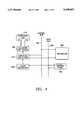
- FIG. 1is the functional block diagram of the preferred embodiment of an electronic identification system that comprises a conventional reader and the multi-memory tag.
- FIG. 2is the flow diagram associated with the main program that governs the operations of the controller in the multi-memory electronic identification tag.
- FIG. 3is the flow diagram associated with the routine performed by the controller in the multi-memory electronic identification tag when the bit rate interrupt occurs.
- FIG. 4is the functional block diagram of the preferred embodiment of the programing unit that is used to program the multi-memory electronic identification tag.
- the electronic identification system that utilizes multi-memory tagsis comprised of a reader that is capable of interrogating and receiving information from a multi-memory tag, a programming unit that is capable of reprogramming the reprogrammable portion of the memory of the multi-memory tag, and a multi-memory tag that is capable of transmitting data to the reader and receiving data and commands from the programming unit.
- the functional block diagrams of the preferred embodiments of the reader and the multi-memory tagare shown in FIG. 1.
- the reader 100interrogates the tag 200 by generating a reversing magnetic field 10 by means of the wound wire coil 110 that is inductively coupled to a similar coil 220 in the tag 200.
- the coil 110 in series with capacitor pair 120is driven by the double-ended balanced coil driver 135 with a periodic signal of appropriate frequency supplied by the clock generator 140.
- the driving frequencyis in the range from 100 kHz to 400 kHz.
- a typical design for balanced drivers suitable for driving the coil 110 and capacitors 120is the commercially-available integrated circuit SI995ODY which comprises a complementary pair of power metal oxide silicon field effect transistors (power MOSFETS), the output ports of the two transistors being connected to opposite ends of the coil 110 through the two capacitors 120.
- the two transistorsare driven by complementary waveforms, the second waveform being an inverted version of the first.
- the two capacitors 120have equal capacitances, the capacitance being chosen so that the combination of the coil and capacitor pair constitutes a series resonant circuit at a desired driving frequency.
- the clock generator 140is comprised of a crystal-controlled oscillator and divider chains of conventional design.
- the oscillator frequencyis chosen such that all required driving frequencies can be obtained by integer divisions.
- the clock generator 140includes a duty cycle timer which generates a square-wave timing signal that causes the reader coil 110 to be energized when the signal is high.
- the signalremains high for a time long enough to receive the information to be communicated by a tag on the particular driving frequency being used.
- the signalremains low for a time long enough for the reader 100 to be moved to a new reading position.
- the purpose of operating the reader coil 110 with a duty cycleis to conserve battery power and achieve longer operating periods between battery rechargings or replacements.
- the duty cycle timeris set to low by the microprocessor 170 whenever the microprocessor recognizes a condition that indicates failure of the read process.
- the duty cycle timerturns on only when the reader power switch is on and the user-activated "read” trigger switch 142 is closed. Releasing the "read” trigger does not disable the duty cycle timer until the normal transition from high to low occurs.
- Time Tis maintained in the clock generator 140 by a counter that counts cycles of the driving frequency when the duty cycle timer signal is high.
- the counteris reset each time the duty cycle timer signal goes from high to low.
- the T countercan be accessed by the microprocessor 170 by means of the control bus 187 and data bus 190.
- the T countersupplies an interrupt signal to the microprocessor 170 when T equals T 1 where T 1 is the time required for the reader coil voltage to approach within say 0.1% of its steady-state voltage. When the T 1 interrupt occurs, signal processing in the reader begins.
- the tag 200In response to an interrogation by the reader 100, the tag 200 causes the variable load 230 that is inductively coupled to the reader coil 110 by means of coil 210 to vary in accordance with one or the other of two patterns, one pattern being associated with the transmission of a 0 and the other being associated with the transmission of a 1.
- the loading patternis manifested at the reader by a variation in the voltage across the reader coil 110.
- the demodulator 150performs those operations necessary to determine whether the voltage pattern during a bit period corresponds to a 0 or a 1 and periodically communicates this determination to the microprocessor 170 by means of the data bus 190.
- the tag data that derives from this information together with operational informationis caused by the microprocessor 170 to be visually displayed on alphanumeric display 175. This same information is made available audibly to the user in the form of audio signals and/or artificial speech by means of the audio interface 180 and the speaker 185.
- the microprocessor 170exercises control over the clock generator 140, the demodulator 150, the alpha-numeric display 175, and the audio interface 180 by means of the control bus 187. Data is exchanged between the microprocessor 170 and the clock generator 140, the demodulator 150, the alpha-numeric display 175, and the audio interface 180 by means of the data bus 190.
- An external digital computer 195can exercise control over and exchange data with the microprocessor 170 by means of the standard RS-232 data link 197.
- the tag 200when in the proximity of and inductively-coupled to the reader 100, extracts power from the alternating magnetic field 10 established by the reader coil 110 by means of the multi-turn coiled conductor 210 in parallel with the capacitor 220, the combination constituting a resonant circuit at one of the reader's driving frequencies.
- variable load 230is connected across the coil-capacitor combination thereby providing a means for varying the load on the balanced coil driver 135 in the reader 100 resulting from the inductive coupling of the reader and tag coils.
- the variable load 230is resistive in the preferred embodiment thereby achieving the greatest possible effectiveness in absorbing power from the reversing magnetic field and in communicating with the reader.
- Other less desirable embodimentscould use loads that are inductive, capacitive, or some combination of inductive, capacitive, and resistive.
- the communication capability of the reader 100 and the tag 200are critically dependent on the characteristics of the reader coil 110 and the tag coil 210.
- the number of turns for the reader coilshould be as large as possible so that the magnetic field created by the reader coil is as large as possible.
- the resistance of the reader coil 110(proportional to the number of turns) must not become so large as to be a substantial mismatch to the driving impedance and thereby impede the transfer of power to the tag.
- the preferred embodiment of the reader coilis wound on an oval plastic core approximately 45/8 inches long by 33/4 inches wide.
- the coilis wound with 90 to 100 turns of 28-gauge wire yielding a coil with approximate inductance of 2.3 mH and approximate resistance of 7.6 ohms.
- the number of turns on the tag coil 210also should be as large as possible in order to maximize the inductively-generated voltage across the coil. Again caution must be exercised in choosing the number of turns so that the power transfer between reader and tag is not adversely affected.
- the alternating voltage appearing across the coil 210 as a result of being inductively coupled to the reader coil 110is converted to direct current by means of the AC/DC converter and voltage regulator 235 which supplies all of the power required by the tag circuitry.
- the alternating voltage appearing across the coil 210provides a reference frequency for the clock generator 240 which supplies all of the clocking signals required by the tag circuitry.
- Another embodimentutilizes the alternating coil voltage to stabilize a voltage-controlled oscillator which would then act as the source for all clocking signals.
- the controller 245controls all of the operations performed by the tag circuitry by means of control bus 246 and data bus 248.
- a clock signal for the controller 245is supplied by the clock generator 240.
- the threshold detector 250produces a signal when the voltage from the AC/DC converter and voltage regulator 235 reaches the level required for reliable operation of the tag circuitry.
- the threshold detector 250is a simple comparison circuit that uses a Zener diode as a reference voltage.
- the signal from the threshold detector 250serves to reset the controller 245 which waits for a first predetermined period of time (measured by a clock cycle counter in the controller) for the purpose of allowing the voltage transient associated with the inductive coupling of an externally-generated magnetic field to the tag coil 210 to die down to the point where either power absorption by the tag can be detected by the reader or amplitude modulation by the programming unit can be detected by the tag.
- the controller 245waits for a second predetermined period of time (also measured by a clock cycle counter in the controller) for the purpose of allowing the demodulator 244 time enough to discover whether the interrogation is by the programming unit rather than the reader.
- the demodulator 244is enabled by the controller 245 at the expiration of the first predetermined time period.
- the demodulator 244first extracts the modulating signal (if such exists) in the same manner as the reader demodulator 150 by taking the difference between two smoothed versions of the rectified coil signal, one of the smoothed versions being obtained by smoothing the rectified coil signal over a time period that is long compared to the period of the coil signal and short compared to the period of the bits that are transmitted by the programming unit, the other of the smoothed versions being obtained by smoothing the rectified coil signal over a time period that is long compared to the bit period.
- the coil signalhas a frequency of a few hundred kHz and the bit rate is a few kHz. These numbers suggest a smoothing time somewhere in the range of 10 to 20 coil signal periods for the first smoothed version.
- the smoothed versionshould be smoothed for at least 10 bit periods.
- the programming unitinitially transmits an alternating series of "0's" and '1's" for the purpose of allowing the demodulator 244 to recognize the presence of a modulating signal.
- the demodulatorrecognizes the modulating signal presence by smoothing the rectified difference signal for at least ten bit periods and comparing the smoothed rectified difference signal with a predetermined threshold voltage which is three to five times the standard deviation of the noise appearing across the coil 210 and the capacitor 220. If the smoothed rectified difference signal is greater than the threshold voltage, the demodulator concludes that a modulating signal is present and sets the "modulation present" flag which can be read by the controller 245.
- the threshold voltageis preferably established at such a level that the probability of falsely recognizing the presence of a modulating signal is less than 0.01 and the probability of recognizing the presence of a modulating signal that is truly present is greater than 0.99.
- the demodulation processcontinues with the demodulator 244 identifying the peaks and valleys of the difference signal and thereby generating a bit rate clock signal which is a square wave having a frequency equal to the bit rate and having low-to-high transitions that coincide with the peaks and valleys of the difference signal.
- the demodulatoridentifies a bit by observing the sign of the difference signal when a positive transition of the bit rate clock signal occurs. If the difference signal is negative, the received bit is a "0". If the difference signal is positive, the received bit is a "1".
- the demodulator 244can be implemented in a number of ways.
- An example of a suitable implementationis given in the aforereferenced Beigel patent in connection with the description of the preferred embodiment of the reader amplitude demodulator.
- the bit rate clock signalalerts the controller 245 each time a bit decision is made whereupon the controller retrieves the bit and saves it in memory.
- the programming unittransmits a "start message” code following the alternating series of "0's" and "1's". If a "start" message code is not received by the end of the second predetermined time period, the controller 245 concludes that the interrogation is by a reader rather than a programming unit and proceeds to transmit the data stored in memory to the reader.
- a messageis transmitted by the controller 245 by applying a square wave signal of appropriate frequency to the variable load 230 for each bit of the message.
- the controller 245retrieves for transmission all but the sensor data portion of the message from the nonvolatile memories 252 and 258.
- the electrically-erasable programmable read-only memory (EEPROM) 252contains data that the user of the tag may wish to change sometime in the future. The user changes the data by transmitting an appropriate message via the programming unit to the tag whereupon the controller 245 causes the EEPROM programmer 254 to reprogram the EEPROM 252 with data included in-the message.
- the EEPROM 252can also be reprogrammed by using standard reprogramming circuitry that connects directly to contacts on the device, when such contacts are accessible.
- the reprogramming of the EEPROMcan be permanently inhibited during initial programming, prior to implantation in or attachment to the object to be identified, by breaking a fused connection (i.e., "blowing" a fuse) in the EEPROM by the application of a voltage of sufficient magnitude to the input port 256 of the EEPROM.
- the laser-programmable read-only memory (laser PROM) 258contains data which uniquely identifies the tag and is unalterable because of the nature of the laser PROM. The manufacturer utilizes this data in providing warranty and diagnostic services to the user.
- the laser PROMis permanently programmed at the time of manufacture by utilizing a laser beam to make or break connections in the device.
- the controller 245obtains the sensor data from a first-in/first-out (FIFO) memory device 259 where the data was stored as a result of the sensor selector 260 connecting the A/D converter 265 sequentially first to temperature sensor 270 and then to PH sensor 275.
- FIFOfirst-in/first-out
- variable load 230In the absence of a message transmission from the controller 245, the variable load 230 is dormant and does not appreciably load the resonant circuit 210, 220.
- the controllertransmits a message over line 238 to the variable load 230, the variable load applies a load to the resonant circuit 210, 220 in accordance with a frequency-shift-keying (FSK) technique.
- FSKfrequency-shift-keying
- the "space” frequency signalcauses the load to be turned on or off depending on the high and low states of the "space” frequency signal.
- the "mark" and “space” square-wave signalsare derived from the reader driving frequency and supplied by the clock generator 240 to the variable load 230 over lines 242.
- the readermay advantageously extract the information from the power absorption signal by means of a coherent demodulation technique thereby realizing the increased communication efficiency of coherent frequency-shift keying (CFSK) as compared to non-coherent frequency shift keying (NCFSK).
- CFSKcoherent frequency-shift keying
- NCFSKnon-coherent frequency shift keying
- the "mark” and “space” frequenciesare chosen small enough that the sidebands resulting from the amplitude modulation of the driving-frequency signal are not attenuated by more than say 3 dB with respect to the driving frequency by the reader resonant circuit 110, 120.
- the spacing of the "mark” and “space” frequenciesshould ideally be an integer times the bit rate where the integer is preferably equal to or greater than two. For a driving frequency of 400 kHz and a bit rate of 5 kHz and 40 kHz respectively. Note that the difference 10 kHz is equal to the integer 2 times the bit rate.
- the tagcould utilize on-off-keying (OOK) whereby the variable load 230 turns the load off when a "0" is transmitted and turns the load on and off when a "1" is transmitted (or vice versa) in accordance with whether a square wave of predetermined frequency supplied by the clock 240 is high or low.
- OOKon-off-keying
- Phase-shift-keyingin either the fully-coherent (CPSK) or differentially-coherent (DCPSK) versions could also be used. Coherent phase-shift-keying would result if the variable load 230 turned the load on or off in accordance with whether the square wave described above was high or low respectively when a "0" was transmitted and turned the load on or off when the square wave was low or high respectively when a "1" was transmitted (or vice versa).
- variable load 230turned the load on and off in the same way as it was during the previous bit period when a "0" is transmitted and in the opposite way when a "1" is transmitted.
- the operations performed by the controller 245 in the tag 200are detailed in the flow diagram shown in FIG. 2.
- the reset of the controller 245 (FIG. 1) by the threshold detector 250 (FIG. 1)causes the controller registers to be cleared and directs the controller to perform the sequence of operations beginning at the main program address 300.
- the controllerfirst performs operations 305. It waits for a predetermined time long enough for the voltage transient that results from the coupling of a magnetic field to the coil 210 (FIG. 1) to die down to a level low enough to permit the demodulation of coil signals by either the reader 100 or the tag 200 (FIG. 1). It then enables the demodulator 244 (FIG. 1) and waits for a predetermined time that is long enough for the demodulator to determine whether the coil signal is modulated.
- the controllerreads the "modulation present" flag in the demodulator to determine whether the coil signal is modulated 310. If modulation is not present, the controller transmits 315 a message consisting of the data stored in the laser PROM, the EEPROM, and the FIFO memory.
- the controllerIf modulation is present, the controller enables 320 the bit rate interrupt, the bit rate signal being supplied by the demodulator. The controller then waits 325 for the bit rate interrupt to be disabled in the bit rate interrupt routine.
- the controllerdetermines 325 that the bit rate interrupt has been disabled, it performs test 330. If the "EEPROM data” flag was set, the controller reprograms the EEPROM in accordance with the data received from the programming unit. If the "EEPROM data” flag was not set 330, the controller closes down until the next interrogation.
- bit rate interruptWhen the bit rate interrupt is enabled, a positive transition of the bit rate clock signal supplied by the demodulator 244 (FIG. 1) causes the main program shown in FIG. 2 to be interrupted and the controller is directed to the address in memory of the bit rate interrupt routine shown in FIG. 3.
- the registers identified in this routinewere cleared and the flags reset when the controller 245 was reset by the threshold device 250 when an interrogation first occurred (see discussion in connection with FIG. 1).
- the controllerbegins the routine by reading 340 the bit just demodulated by the demodulator. The controller then determines whether the "reprogram" flag is set 345.
Landscapes
- Engineering & Computer Science (AREA)
- Computer Networks & Wireless Communication (AREA)
- Computer Hardware Design (AREA)
- Microelectronics & Electronic Packaging (AREA)
- Physics & Mathematics (AREA)
- General Physics & Mathematics (AREA)
- Theoretical Computer Science (AREA)
- Near-Field Transmission Systems (AREA)
Abstract
Description
Claims (20)
Priority Applications (1)
| Application Number | Priority Date | Filing Date | Title |
|---|---|---|---|
| US08/244,583US5499017A (en) | 1992-12-02 | 1992-12-02 | Multi-memory electronic identification tag |
Applications Claiming Priority (2)
| Application Number | Priority Date | Filing Date | Title |
|---|---|---|---|
| PCT/US1992/010398WO1993011517A1 (en) | 1991-12-03 | 1992-12-02 | Multi-memory electronic identification tag |
| US08/244,583US5499017A (en) | 1992-12-02 | 1992-12-02 | Multi-memory electronic identification tag |
Publications (1)
| Publication Number | Publication Date |
|---|---|
| US5499017Atrue US5499017A (en) | 1996-03-12 |
Family
ID=22923345
Family Applications (1)
| Application Number | Title | Priority Date | Filing Date |
|---|---|---|---|
| US08/244,583Expired - LifetimeUS5499017A (en) | 1992-12-02 | 1992-12-02 | Multi-memory electronic identification tag |
Country Status (1)
| Country | Link |
|---|---|
| US (1) | US5499017A (en) |
Cited By (74)
| Publication number | Priority date | Publication date | Assignee | Title |
|---|---|---|---|---|
| US5699046A (en)* | 1995-11-02 | 1997-12-16 | Sensormatic Electronics Corporation | EAS system employing central and local stations with shared functions |
| US5721535A (en)* | 1904-05-27 | 1998-02-24 | Rohm Co., Ltd. | Tag responsive to high frequency for varying capacitance of capacitor in power source |
| US5745036A (en)* | 1996-09-12 | 1998-04-28 | Checkpoint Systems, Inc. | Electronic article security system for store which uses intelligent security tags and transaction data |
| US5774062A (en)* | 1994-05-27 | 1998-06-30 | Rohm Co., Ltd. | Tag responsive to high-frequecy for varying capacitance of tuning capacitor |
| US5874896A (en)* | 1996-08-26 | 1999-02-23 | Palomar Technologies Corporation | Electronic anti-shoplifting system employing an RFID tag |
| EP0849734A3 (en)* | 1996-12-20 | 1999-03-24 | Texas Instruments Incorporated | Improvements in or relating to security systems |
| EP0809245A3 (en)* | 1996-05-02 | 1999-03-24 | Texas Instruments Incorporated | Improvements in or relating to security systems |
| US5963134A (en)* | 1997-07-24 | 1999-10-05 | Checkpoint Systems, Inc. | Inventory system using articles with RFID tags |
| US6002344A (en)* | 1997-11-21 | 1999-12-14 | Bandy; William R. | System and method for electronic inventory |
| US6025780A (en)* | 1997-07-25 | 2000-02-15 | Checkpoint Systems, Inc. | RFID tags which are virtually activated and/or deactivated and apparatus and methods of using same in an electronic security system |
| WO2000062263A1 (en) | 1999-04-13 | 2000-10-19 | Electronic Data Identification Limited | Terminal for an active labelling system |
| US6154137A (en)* | 1998-06-08 | 2000-11-28 | 3M Innovative Properties Company | Identification tag with enhanced security |
| US6169474B1 (en)* | 1998-04-23 | 2001-01-02 | Micron Technology, Inc. | Method of communications in a backscatter system, interrogator, and backscatter communications system |
| US6232870B1 (en) | 1998-08-14 | 2001-05-15 | 3M Innovative Properties Company | Applications for radio frequency identification systems |
| US6249212B1 (en)* | 1994-10-05 | 2001-06-19 | Avid Marketing, Inc. | Universal electronic identification tag |
| WO2001051369A1 (en)* | 2000-01-10 | 2001-07-19 | Moore North America, Inc. | Radio frequency labels on reusable containers |
| US6320169B1 (en) | 1999-09-07 | 2001-11-20 | Thermal Solutions, Inc. | Method and apparatus for magnetic induction heating using radio frequency identification of object to be heated |
| US6335686B1 (en) | 1998-08-14 | 2002-01-01 | 3M Innovative Properties Company | Application for a radio frequency identification system |
| US6366206B1 (en)* | 1999-06-02 | 2002-04-02 | Ball Semiconductor, Inc. | Method and apparatus for attaching tags to medical and non-medical devices |
| US6424262B2 (en) | 1998-08-14 | 2002-07-23 | 3M Innovative Properties Company | Applications for radio frequency identification systems |
| US20020149480A1 (en)* | 2001-02-12 | 2002-10-17 | Matrics, Inc. | Method, system, and apparatus for remote data calibration of a RFID tag population |
| US20020154029A1 (en)* | 1999-02-26 | 2002-10-24 | Sri International | Sensor devices for structural health monitoring |
| WO2002084615A1 (en)* | 2001-04-12 | 2002-10-24 | Elliot Klein | Lost and found system and method with optional product warranty registration |
| US6472975B1 (en)* | 1994-06-20 | 2002-10-29 | Avid Marketing, Inc. | Electronic identification system with improved sensitivity |
| US20020185532A1 (en)* | 2001-06-07 | 2002-12-12 | Berquist David T. | RFID data collection and use |
| US6510986B1 (en)* | 1999-05-06 | 2003-01-28 | Fujitsu Limited | Transaction record storing device and transaction machine including same |
| WO2003008037A3 (en)* | 2001-07-17 | 2003-05-22 | Medtronic Inc | Automatic implantable medical lead recognition and configuration |
| US20030128124A1 (en)* | 2001-12-17 | 2003-07-10 | Franz Amtmann | Communication station for inventorizing transponders by means of selectable memory areas of the transponders |
| US6617963B1 (en) | 1999-02-26 | 2003-09-09 | Sri International | Event-recording devices with identification codes |
| US20030214389A1 (en)* | 2002-04-01 | 2003-11-20 | Matrics, Inc. | Method and system for optimizing an interrogation of a tag population |
| WO2004006248A1 (en)* | 2002-07-08 | 2004-01-15 | Koninklijke Philips Electronics N.V. | Data retention of integrated circuit on record carrier |
| US20040017295A1 (en)* | 1999-12-20 | 2004-01-29 | Dishongh Terrance J. | Electrically modifiable product labeling |
| US6712276B1 (en)* | 1999-01-29 | 2004-03-30 | International Business Machines Corporation | Method and apparatus for automated measurement of properties of perishable consumer products |
| US20040069851A1 (en)* | 2001-03-13 | 2004-04-15 | Grunes Mitchell B. | Radio frequency identification reader with removable media |
| US6735310B1 (en) | 1999-09-17 | 2004-05-11 | International Business Machines Corporation | Technique of password encryption and decryption for user authentication in a federated content management system |
| US20040111338A1 (en)* | 1997-11-21 | 2004-06-10 | Matrics, Inc. | System and method for electronic inventory |
| US20040134984A1 (en)* | 2002-10-25 | 2004-07-15 | Powell Kevin J. | Optimization of a binary tree traversal with secure communications |
| US20040149736A1 (en)* | 2003-01-30 | 2004-08-05 | Thermal Solutions, Inc. | RFID-controlled smart induction range and method of cooking and heating |
| US20040155106A1 (en)* | 2002-11-15 | 2004-08-12 | Schmidtberg Rupert A. | Methods and apparatus for communicating condition information associated with an item |
| US6806808B1 (en) | 1999-02-26 | 2004-10-19 | Sri International | Wireless event-recording device with identification codes |
| US20040217171A1 (en)* | 2003-04-29 | 2004-11-04 | Devos John A. | Electronic identification label and interrogator for use therewith |
| US20050032151A1 (en)* | 2001-06-05 | 2005-02-10 | Eisenberg Peter M. | Methods of managing the transfer and use of data |
| US20050070811A1 (en)* | 2003-09-30 | 2005-03-31 | Crowley Christopher T. | Non-contact patient temperature measurement |
| US20050116826A1 (en)* | 2003-12-02 | 2005-06-02 | Shalom Wertsebrger | Method for Partial Disablement of Radio Frequency Identification Tags and Tags for Use Therewith |
| US20050182598A1 (en)* | 1999-09-03 | 2005-08-18 | Reel Greg T. | Method and system for procuring, storing and distributing remotely accessed data gathered by logging devices |
| US20050234587A1 (en)* | 2004-03-31 | 2005-10-20 | Toshiba Tec Kabushiki Kaisha | Tag unit and reading/writing apparatus therefor |
| US20050246233A1 (en)* | 2004-03-30 | 2005-11-03 | Nathan Daniel Estruth | Method of selling and activating consumer products and services |
| US20050247696A1 (en)* | 2004-04-22 | 2005-11-10 | Clothier Brian L | Boil detection method and computer program |
| US7000834B2 (en)* | 2001-02-21 | 2006-02-21 | International Business Machines Corporation | Method to address security and privacy issue of the use of RFID systems to track consumer products |
| US7044373B1 (en) | 1998-08-14 | 2006-05-16 | 3M Innovative Properties Company | Radio frequency identification systems applications |
| US20060261950A1 (en)* | 2005-03-29 | 2006-11-23 | Symbol Technologies, Inc. | Smart radio frequency identification (RFID) items |
| US20060261947A1 (en)* | 2005-05-20 | 2006-11-23 | Xerox Corporation | Coupler board for wireless communication with multiple memory devices |
| US20070034686A1 (en)* | 2005-08-15 | 2007-02-15 | Davis Michael L | Protection of non-promiscuous data in an rfid transponder |
| US20070034691A1 (en)* | 2005-08-15 | 2007-02-15 | Davis Michael L | Using promiscuous and non-promiscuous data to verify card and reader identity |
| US20070060311A1 (en)* | 2005-09-12 | 2007-03-15 | Igt | Enhanced gaming chips and table game security |
| US20070112397A1 (en)* | 2005-11-16 | 2007-05-17 | Codman Neuro Sciences Sarl | Continuous phase frequency shift keying modulation during wireless transmissions in a closed system while minimizing power consumption |
| US20070198121A1 (en)* | 2005-10-21 | 2007-08-23 | Yu Zheng | Interactive clothing system |
| US20080117021A1 (en)* | 2006-11-20 | 2008-05-22 | Kevin Michael Brunski | Method of placing and using an electronic identification transponder |
| US7398379B1 (en)* | 2005-05-02 | 2008-07-08 | Altera Corporation | Programmable logic device integrated circuits with wireless programming |
| US20080307197A1 (en)* | 2007-06-05 | 2008-12-11 | Calvin Duane A | System and Method for Persistent Hardware System Serial Numbers |
| US20090284310A1 (en)* | 2004-02-06 | 2009-11-19 | Semiconductor Energy Laboratory Co., Ltd. | Semiconductor device |
| US20090303019A1 (en)* | 2008-06-04 | 2009-12-10 | Alcatel-Lucent | Method for providing a service based on tag information, and corresponding tag and tag reading device |
| US7844505B1 (en) | 1997-11-21 | 2010-11-30 | Symbol Technologies, Inc. | Automated real-time distributed tag reader network |
| US20100327634A1 (en)* | 2007-11-12 | 2010-12-30 | Be Aerospace, Inc. | Convertible passenger seat assembly |
| US20110026499A1 (en)* | 1994-06-24 | 2011-02-03 | Gpne Corp. | Communication system with a mapping system allowing nodes to register with a controller |
| US7978078B2 (en)* | 2001-12-21 | 2011-07-12 | Sensormatic Electronics, LLC | Magnetic core transceiver for electronic article surveillance marker detection |
| US8002182B2 (en) | 1998-04-10 | 2011-08-23 | 3M Innovative Properties Company | System for processing financial transactions in a self-service library terminal |
| US20120126948A1 (en)* | 2006-11-20 | 2012-05-24 | Kevin Michael Brunski | Identification system and method |
| WO2013084242A2 (en) | 2011-12-07 | 2013-06-13 | Rao Css | System and method for providing a secure electronic identification and management system for livestock with ownership interface, e-governance and global supply chain traceability for products of animal origin |
| US20160080391A1 (en)* | 2014-09-12 | 2016-03-17 | International Business Machines Corporation | System for monitoring access to network within secured site |
| US9618421B2 (en)* | 2013-07-31 | 2017-04-11 | Opticallock, Inc. | Method and optical shield for detecting tampering |
| US9990866B2 (en) | 2013-07-31 | 2018-06-05 | Opticallock, Inc. | Container tamper-proof protection by use of printed fiber optics manufacturing and integrated sensors |
| US10107014B2 (en) | 2015-08-30 | 2018-10-23 | Opticallock, Inc. | Security system with anti-tampering sensors and cybersecurity |
| US20210342660A1 (en)* | 2019-01-17 | 2021-11-04 | Excelio Technology (Shenzhen) Co., Ltd. | Circuit And Method of Improving Energy Harvesting for Radio Frequency Identification (RFID) Tag with Temperature Sensor |
Citations (5)
| Publication number | Priority date | Publication date | Assignee | Title |
|---|---|---|---|---|
| US4656463A (en)* | 1983-04-21 | 1987-04-07 | Intelli-Tech Corporation | LIMIS systems, devices and methods |
| US4724427A (en)* | 1986-07-18 | 1988-02-09 | B. I. Incorporated | Transponder device |
| US5103222A (en)* | 1987-07-03 | 1992-04-07 | N.V. Nederlandsche Apparatenfabriek Nedap | Electronic identification system |
| US5214409A (en)* | 1991-12-03 | 1993-05-25 | Avid Corporation | Multi-memory electronic identification tag |
| US5257011A (en)* | 1991-12-03 | 1993-10-26 | Avid Corporation | Data altering means for multi-memory electronic identification tag |
- 1992
- 1992-12-02USUS08/244,583patent/US5499017A/ennot_activeExpired - Lifetime
Patent Citations (5)
| Publication number | Priority date | Publication date | Assignee | Title |
|---|---|---|---|---|
| US4656463A (en)* | 1983-04-21 | 1987-04-07 | Intelli-Tech Corporation | LIMIS systems, devices and methods |
| US4724427A (en)* | 1986-07-18 | 1988-02-09 | B. I. Incorporated | Transponder device |
| US5103222A (en)* | 1987-07-03 | 1992-04-07 | N.V. Nederlandsche Apparatenfabriek Nedap | Electronic identification system |
| US5214409A (en)* | 1991-12-03 | 1993-05-25 | Avid Corporation | Multi-memory electronic identification tag |
| US5257011A (en)* | 1991-12-03 | 1993-10-26 | Avid Corporation | Data altering means for multi-memory electronic identification tag |
Cited By (161)
| Publication number | Priority date | Publication date | Assignee | Title |
|---|---|---|---|---|
| US5721535A (en)* | 1904-05-27 | 1998-02-24 | Rohm Co., Ltd. | Tag responsive to high frequency for varying capacitance of capacitor in power source |
| US5774062A (en)* | 1994-05-27 | 1998-06-30 | Rohm Co., Ltd. | Tag responsive to high-frequecy for varying capacitance of tuning capacitor |
| US6472975B1 (en)* | 1994-06-20 | 2002-10-29 | Avid Marketing, Inc. | Electronic identification system with improved sensitivity |
| US20110026499A1 (en)* | 1994-06-24 | 2011-02-03 | Gpne Corp. | Communication system with a mapping system allowing nodes to register with a controller |
| US8559404B2 (en) | 1994-06-24 | 2013-10-15 | Gpne Corp. | Communication system with connections made using randomly generated information and variable frame boundaries |
| US8335195B2 (en) | 1994-06-24 | 2012-12-18 | GPNE Corporation | Communication system allowing node identification |
| US6249212B1 (en)* | 1994-10-05 | 2001-06-19 | Avid Marketing, Inc. | Universal electronic identification tag |
| US5699046A (en)* | 1995-11-02 | 1997-12-16 | Sensormatic Electronics Corporation | EAS system employing central and local stations with shared functions |
| EP0809245A3 (en)* | 1996-05-02 | 1999-03-24 | Texas Instruments Incorporated | Improvements in or relating to security systems |
| AU712986B2 (en)* | 1996-08-26 | 1999-11-18 | Hid Corporation | Electronic anti-shoplifting system employing an RFID tag |
| US5874896A (en)* | 1996-08-26 | 1999-02-23 | Palomar Technologies Corporation | Electronic anti-shoplifting system employing an RFID tag |
| US5745036A (en)* | 1996-09-12 | 1998-04-28 | Checkpoint Systems, Inc. | Electronic article security system for store which uses intelligent security tags and transaction data |
| EP0849734A3 (en)* | 1996-12-20 | 1999-03-24 | Texas Instruments Incorporated | Improvements in or relating to security systems |
| US6693539B2 (en) | 1997-07-24 | 2004-02-17 | Checkpoint Systems, Inc. | Inventory system using articles with RFID tags |
| US6195006B1 (en) | 1997-07-24 | 2001-02-27 | Checkpoint Systems Inc. | Inventory system using articles with RFID tags |
| US5963134A (en)* | 1997-07-24 | 1999-10-05 | Checkpoint Systems, Inc. | Inventory system using articles with RFID tags |
| US6025780A (en)* | 1997-07-25 | 2000-02-15 | Checkpoint Systems, Inc. | RFID tags which are virtually activated and/or deactivated and apparatus and methods of using same in an electronic security system |
| US7844505B1 (en) | 1997-11-21 | 2010-11-30 | Symbol Technologies, Inc. | Automated real-time distributed tag reader network |
| US6002344A (en)* | 1997-11-21 | 1999-12-14 | Bandy; William R. | System and method for electronic inventory |
| US20040111338A1 (en)* | 1997-11-21 | 2004-06-10 | Matrics, Inc. | System and method for electronic inventory |
| US7035818B1 (en) | 1997-11-21 | 2006-04-25 | Symbol Technologies, Inc. | System and method for electronic inventory |
| US8322614B2 (en) | 1998-04-10 | 2012-12-04 | 3M Innovative Properties Company | System for processing financial transactions in a self-service library terminal |
| US8002182B2 (en) | 1998-04-10 | 2011-08-23 | 3M Innovative Properties Company | System for processing financial transactions in a self-service library terminal |
| US6169474B1 (en)* | 1998-04-23 | 2001-01-02 | Micron Technology, Inc. | Method of communications in a backscatter system, interrogator, and backscatter communications system |
| US6154137A (en)* | 1998-06-08 | 2000-11-28 | 3M Innovative Properties Company | Identification tag with enhanced security |
| US6646554B1 (en) | 1998-06-08 | 2003-11-11 | 3M Innovative Properties Company | Identification tag with enhanced security |
| US7619529B2 (en) | 1998-08-14 | 2009-11-17 | 3M Innovative Properties Company | Application for a radio frequency identification system |
| US6448886B2 (en) | 1998-08-14 | 2002-09-10 | 3M Innovative Properties Company | Application for radio frequency identification systems |
| US7471205B2 (en) | 1998-08-14 | 2008-12-30 | 3M Innovative Properties Company | Applications for radio frequency identification systems |
| US6486780B1 (en) | 1998-08-14 | 2002-11-26 | 3M Innovative Properties Company | Applications for radio frequency identification systems |
| US8006902B2 (en) | 1998-08-14 | 2011-08-30 | 3M Innovative Properties Company | Radio frequency identification systems applications |
| US20040201479A1 (en)* | 1998-08-14 | 2004-10-14 | 3M Innovative Properties Company | Applications for radio frequency identification systems |
| US6232870B1 (en) | 1998-08-14 | 2001-05-15 | 3M Innovative Properties Company | Applications for radio frequency identification systems |
| US20060145854A1 (en)* | 1998-08-14 | 2006-07-06 | 3M Innovative Properties Company | Applications for radio frequency identification systems |
| US7044373B1 (en) | 1998-08-14 | 2006-05-16 | 3M Innovative Properties Company | Radio frequency identification systems applications |
| US6600420B2 (en) | 1998-08-14 | 2003-07-29 | 3M Innovative Properties Company | Application for a radio frequency identification system |
| US6768419B2 (en) | 1998-08-14 | 2004-07-27 | 3M Innovative Properties Company | Applications for radio frequency identification systems |
| US20030206107A1 (en)* | 1998-08-14 | 2003-11-06 | 3M Innovative Properties Company | Application for a radio frequency identification system |
| US8502673B2 (en) | 1998-08-14 | 2013-08-06 | 3M Innovative Properties Company | Applications for radio frequency identification systems |
| US7123151B2 (en) | 1998-08-14 | 2006-10-17 | 3M Innovative Properties Company | Applications for radio frequency identification systems |
| US6335686B1 (en) | 1998-08-14 | 2002-01-01 | 3M Innovative Properties Company | Application for a radio frequency identification system |
| US7270268B2 (en) | 1998-08-14 | 2007-09-18 | 3M Innovative Properties Company | Radio frequency identification systems applications |
| US7728732B2 (en) | 1998-08-14 | 2010-06-01 | 3M Innovative Properties Company | Applications for radio frequency identification systems |
| US7113094B2 (en) | 1998-08-14 | 2006-09-26 | 3M Innovative Properties Company | Applications for radio frequency identification systems |
| US6424262B2 (en) | 1998-08-14 | 2002-07-23 | 3M Innovative Properties Company | Applications for radio frequency identification systems |
| US6712276B1 (en)* | 1999-01-29 | 2004-03-30 | International Business Machines Corporation | Method and apparatus for automated measurement of properties of perishable consumer products |
| US7986218B2 (en) | 1999-02-26 | 2011-07-26 | Yasumi Capital, Llc | Sensor devices for structural health monitoring |
| US20060170535A1 (en)* | 1999-02-26 | 2006-08-03 | Sri International | Sensor devices for structural health monitoring |
| US7034660B2 (en) | 1999-02-26 | 2006-04-25 | Sri International | Sensor devices for structural health monitoring |
| US20020154029A1 (en)* | 1999-02-26 | 2002-10-24 | Sri International | Sensor devices for structural health monitoring |
| US6617963B1 (en) | 1999-02-26 | 2003-09-09 | Sri International | Event-recording devices with identification codes |
| US6806808B1 (en) | 1999-02-26 | 2004-10-19 | Sri International | Wireless event-recording device with identification codes |
| WO2000062263A1 (en) | 1999-04-13 | 2000-10-19 | Electronic Data Identification Limited | Terminal for an active labelling system |
| US6510986B1 (en)* | 1999-05-06 | 2003-01-28 | Fujitsu Limited | Transaction record storing device and transaction machine including same |
| US6366206B1 (en)* | 1999-06-02 | 2002-04-02 | Ball Semiconductor, Inc. | Method and apparatus for attaching tags to medical and non-medical devices |
| US20050182598A1 (en)* | 1999-09-03 | 2005-08-18 | Reel Greg T. | Method and system for procuring, storing and distributing remotely accessed data gathered by logging devices |
| US6320169B1 (en) | 1999-09-07 | 2001-11-20 | Thermal Solutions, Inc. | Method and apparatus for magnetic induction heating using radio frequency identification of object to be heated |
| US6735310B1 (en) | 1999-09-17 | 2004-05-11 | International Business Machines Corporation | Technique of password encryption and decryption for user authentication in a federated content management system |
| US6731221B1 (en)* | 1999-12-20 | 2004-05-04 | Intel Corporation | Electrically modifiable product labeling |
| US20040017295A1 (en)* | 1999-12-20 | 2004-01-29 | Dishongh Terrance J. | Electrically modifiable product labeling |
| US6520544B1 (en) | 2000-01-10 | 2003-02-18 | Moore North America, Inc. | Radio frequency labels on reusable containers |
| WO2001051369A1 (en)* | 2000-01-10 | 2001-07-19 | Moore North America, Inc. | Radio frequency labels on reusable containers |
| US20020149480A1 (en)* | 2001-02-12 | 2002-10-17 | Matrics, Inc. | Method, system, and apparatus for remote data calibration of a RFID tag population |
| US20020167405A1 (en)* | 2001-02-12 | 2002-11-14 | Matrics, Inc. | Radio frequency identification architecture |
| US20050174239A1 (en)* | 2001-02-12 | 2005-08-11 | Symbol Technologies, Inc. | Radio frequency identification tag antenna configurations |
| US7212125B2 (en) | 2001-02-12 | 2007-05-01 | Symbol Technologies, Inc. | Radio frequency identification architecture |
| US7145482B2 (en) | 2001-02-12 | 2006-12-05 | Symbol Technologies, Inc. | Method, system, and apparatus for remote data calibration of a RFID tag population |
| US7965189B2 (en) | 2001-02-12 | 2011-06-21 | Symbol Technologies, Inc. | Radio frequency identification architecture |
| US6956509B2 (en) | 2001-02-12 | 2005-10-18 | Symbol Technologies, Inc. | Method, system, and apparatus for remote data calibration of a RFID tag population |
| US7928843B2 (en) | 2001-02-12 | 2011-04-19 | Symbol Technologies, Inc. | Method, system, and apparatus for communications in a RFID system |
| US20070194933A1 (en)* | 2001-02-12 | 2007-08-23 | Symbol Technologies, Inc. | Radio frequency identification architecture |
| US6784813B2 (en) | 2001-02-12 | 2004-08-31 | Matrics, Inc. | Method, system, and apparatus for remote data calibration of a RFID tag population |
| US7199716B2 (en) | 2001-02-12 | 2007-04-03 | Symbol Technologies, Inc. | Method, system, and apparatus for communicating with a RFID tag population |
| US6989750B2 (en) | 2001-02-12 | 2006-01-24 | Symbol Technologies, Inc. | Radio frequency identification architecture |
| US20020149481A1 (en)* | 2001-02-12 | 2002-10-17 | Matrics, Inc. | Method, system, and apparatus for binary traversal of a tag population |
| US7102523B2 (en) | 2001-02-12 | 2006-09-05 | Symbol Technologies, Inc. | Radio frequency identification tag antenna configurations |
| US20050040974A1 (en)* | 2001-02-12 | 2005-02-24 | Shanks Wayne E. | Method, system, and apparatus for remote data calibration of a RFID tag population |
| US7075436B2 (en) | 2001-02-12 | 2006-07-11 | Symbol Technologies, Inc. | Method, system, and apparatus for binary traversal of a tag population |
| US20060061473A1 (en)* | 2001-02-12 | 2006-03-23 | Symbol Technologies, Inc. | Method, system, and apparatus for communicating with a RFID tag population |
| US20060061474A1 (en)* | 2001-02-12 | 2006-03-23 | Symbol Technologies, Inc. | Method, system, and apparatus for communications in a RFID system |
| US7057511B2 (en) | 2001-02-12 | 2006-06-06 | Symbol Technologies, Inc. | Method, system, and apparatus for communicating with a RFID tag population |
| US20060077082A1 (en)* | 2001-02-12 | 2006-04-13 | Symbol Technologies, Inc. | Method, system, and apparatus for remote data calibration of a RFID tag population |
| US7000834B2 (en)* | 2001-02-21 | 2006-02-21 | International Business Machines Corporation | Method to address security and privacy issue of the use of RFID systems to track consumer products |
| US20040069851A1 (en)* | 2001-03-13 | 2004-04-15 | Grunes Mitchell B. | Radio frequency identification reader with removable media |
| WO2002084615A1 (en)* | 2001-04-12 | 2002-10-24 | Elliot Klein | Lost and found system and method with optional product warranty registration |
| GB2391372A (en)* | 2001-04-12 | 2004-02-04 | Elliot Klein | Lost and found system and method with optional product warranty registration |
| US20050032151A1 (en)* | 2001-06-05 | 2005-02-10 | Eisenberg Peter M. | Methods of managing the transfer and use of data |
| US20020185532A1 (en)* | 2001-06-07 | 2002-12-12 | Berquist David T. | RFID data collection and use |
| US7588185B2 (en) | 2001-06-07 | 2009-09-15 | 3M Innovative Properties Company | RFID data collection and use |
| US20040078067A1 (en)* | 2001-07-17 | 2004-04-22 | Medtronic, Inc. | Method and apparatus for automatic implantable medical lead recognition and configuration |
| WO2003008037A3 (en)* | 2001-07-17 | 2003-05-22 | Medtronic Inc | Automatic implantable medical lead recognition and configuration |
| US20040176822A1 (en)* | 2001-07-17 | 2004-09-09 | Medtronic, Inc. | Method and apparatus for automatic implantable medical lead recognition and configuration |
| US7239916B2 (en) | 2001-07-17 | 2007-07-03 | Medtronic, Inc. | Method and apparatus for automatic implantable medical lead recognition and configuration |
| US6675049B2 (en) | 2001-07-17 | 2004-01-06 | Medtronic, Inc. | Method and apparatus for automatic implantable medical lead recognition and configuration |
| US20030128124A1 (en)* | 2001-12-17 | 2003-07-10 | Franz Amtmann | Communication station for inventorizing transponders by means of selectable memory areas of the transponders |
| US20060097851A1 (en)* | 2001-12-17 | 2006-05-11 | Franz Amtmann | Communication station for inventorizing transponders by means of selectable memory areas of the transponders |
| US6995651B2 (en)* | 2001-12-17 | 2006-02-07 | Koninklijke Phillips Electronics N.V. | Communication station for inventorizing transponders by means of selectable memory areas of the transponders |
| US7786846B2 (en)* | 2001-12-17 | 2010-08-31 | Nxp B.V. | Communication station for inventorizing transponders by means of selectable memory areas of the transponders |
| US7978078B2 (en)* | 2001-12-21 | 2011-07-12 | Sensormatic Electronics, LLC | Magnetic core transceiver for electronic article surveillance marker detection |
| US20030214389A1 (en)* | 2002-04-01 | 2003-11-20 | Matrics, Inc. | Method and system for optimizing an interrogation of a tag population |
| US7009496B2 (en) | 2002-04-01 | 2006-03-07 | Symbol Technologies, Inc. | Method and system for optimizing an interrogation of a tag population |
| US20060170534A1 (en)* | 2002-04-01 | 2006-08-03 | Symbol Technologies, Inc. | Optimizing an interrogation of a tag population |
| WO2004006248A1 (en)* | 2002-07-08 | 2004-01-15 | Koninklijke Philips Electronics N.V. | Data retention of integrated circuit on record carrier |
| US7497384B2 (en) | 2002-10-25 | 2009-03-03 | Symbol Technologies, Inc. | Methods and systems for the negotiation of a population of RFID tags with improved security |
| US7195173B2 (en) | 2002-10-25 | 2007-03-27 | Symbol Technologies, Inc. | Optimization of a binary tree traversal with secure communications |
| US20040134984A1 (en)* | 2002-10-25 | 2004-07-15 | Powell Kevin J. | Optimization of a binary tree traversal with secure communications |
| US20060065731A1 (en)* | 2002-10-25 | 2006-03-30 | Symbol Technologies, Inc. | Methods and systems for the negotiation of a population of RFID tags with improved security |
| US7278571B2 (en) | 2002-11-15 | 2007-10-09 | Sensitech Inc. | Methods and apparatus for communicating condition information associated with an item |
| WO2004046999A3 (en)* | 2002-11-15 | 2005-09-15 | Sensitech Inc | Rf identification reader for communicating condition information associated with the reader |
| US20040155106A1 (en)* | 2002-11-15 | 2004-08-12 | Schmidtberg Rupert A. | Methods and apparatus for communicating condition information associated with an item |
| US20040149736A1 (en)* | 2003-01-30 | 2004-08-05 | Thermal Solutions, Inc. | RFID-controlled smart induction range and method of cooking and heating |
| USRE42513E1 (en) | 2003-01-30 | 2011-07-05 | Hr Technology, Inc. | RFID—controlled smart range and method of cooking and heating |
| US6953919B2 (en) | 2003-01-30 | 2005-10-11 | Thermal Solutions, Inc. | RFID-controlled smart range and method of cooking and heating |
| US20040217171A1 (en)* | 2003-04-29 | 2004-11-04 | Devos John A. | Electronic identification label and interrogator for use therewith |
| US7014112B2 (en) | 2003-04-29 | 2006-03-21 | Hewlett-Packard Development Company, L.P. | Electronic identification label and interrogator for use therewith |
| US20050070811A1 (en)* | 2003-09-30 | 2005-03-31 | Crowley Christopher T. | Non-contact patient temperature measurement |
| US7142114B2 (en)* | 2003-09-30 | 2006-11-28 | General Electric Company | Non-contact patient temperature measurement |
| US20050116826A1 (en)* | 2003-12-02 | 2005-06-02 | Shalom Wertsebrger | Method for Partial Disablement of Radio Frequency Identification Tags and Tags for Use Therewith |
| US7946503B2 (en) | 2004-02-06 | 2011-05-24 | Semiconductor Energy Laboratory Co., Ltd. | Semiconductor device |
| US20110220725A1 (en)* | 2004-02-06 | 2011-09-15 | Semiconductor Energy Laboratory Co., Ltd. | Semiconductor device |
| US20090284310A1 (en)* | 2004-02-06 | 2009-11-19 | Semiconductor Energy Laboratory Co., Ltd. | Semiconductor device |
| US7699232B2 (en) | 2004-02-06 | 2010-04-20 | Semiconductor Energy Laboratory Co., Ltd. | Semiconductor device |
| US8430326B2 (en) | 2004-02-06 | 2013-04-30 | Semiconductor Energy Laboratory Co., Ltd. | Semiconductor device |
| US20080215463A1 (en)* | 2004-03-30 | 2008-09-04 | Nathan Daniel Estruth | Method of Selling and Activating Consumer Products and Services |
| US20050246233A1 (en)* | 2004-03-30 | 2005-11-03 | Nathan Daniel Estruth | Method of selling and activating consumer products and services |
| US7374083B2 (en) | 2004-03-30 | 2008-05-20 | The Procter & Gamble Company | Method of selling and activating consumer products and services |
| US7725368B2 (en) | 2004-03-30 | 2010-05-25 | The Procter & Gamble Company | Method of selling and activating consumer products and services |
| US7250864B2 (en) | 2004-03-31 | 2007-07-31 | Toshiba Tec Kabushiki Kaisha | Reading/writing apparatus of tag unit |
| US20050234587A1 (en)* | 2004-03-31 | 2005-10-20 | Toshiba Tec Kabushiki Kaisha | Tag unit and reading/writing apparatus therefor |
| EP1589470A1 (en)* | 2004-03-31 | 2005-10-26 | Toshiba TEC Kabushiki Kaisha | Tag unit and reading / writing apparatus therefor |
| US20050247696A1 (en)* | 2004-04-22 | 2005-11-10 | Clothier Brian L | Boil detection method and computer program |
| US7573005B2 (en) | 2004-04-22 | 2009-08-11 | Thermal Solutions, Inc. | Boil detection method and computer program |
| US20060261950A1 (en)* | 2005-03-29 | 2006-11-23 | Symbol Technologies, Inc. | Smart radio frequency identification (RFID) items |
| US7398379B1 (en)* | 2005-05-02 | 2008-07-08 | Altera Corporation | Programmable logic device integrated circuits with wireless programming |
| US7307531B2 (en)* | 2005-05-20 | 2007-12-11 | Xerox Corporation | Coupler board for wireless communication with multiple memory devices |
| US20060261947A1 (en)* | 2005-05-20 | 2006-11-23 | Xerox Corporation | Coupler board for wireless communication with multiple memory devices |
| US20070034686A1 (en)* | 2005-08-15 | 2007-02-15 | Davis Michael L | Protection of non-promiscuous data in an rfid transponder |
| US7407110B2 (en)* | 2005-08-15 | 2008-08-05 | Assa Abloy Ab | Protection of non-promiscuous data in an RFID transponder |
| US8322608B2 (en) | 2005-08-15 | 2012-12-04 | Assa Abloy Ab | Using promiscuous and non-promiscuous data to verify card and reader identity |
| US20070034691A1 (en)* | 2005-08-15 | 2007-02-15 | Davis Michael L | Using promiscuous and non-promiscuous data to verify card and reader identity |
| US7938722B2 (en)* | 2005-09-12 | 2011-05-10 | Igt | Enhanced gaming chips and table game security |
| US20070060311A1 (en)* | 2005-09-12 | 2007-03-15 | Igt | Enhanced gaming chips and table game security |
| US20070198121A1 (en)* | 2005-10-21 | 2007-08-23 | Yu Zheng | Interactive clothing system |
| US7808385B2 (en)* | 2005-10-21 | 2010-10-05 | Patent Category Corp. | Interactive clothing system |
| US7450902B2 (en) | 2005-11-16 | 2008-11-11 | Codman Neuro Sciences Sárl | Continuous phase frequency shift keying modulation during wireless transmissions in a closed system while minimizing power consumption |
| US20070112397A1 (en)* | 2005-11-16 | 2007-05-17 | Codman Neuro Sciences Sarl | Continuous phase frequency shift keying modulation during wireless transmissions in a closed system while minimizing power consumption |
| US20080117021A1 (en)* | 2006-11-20 | 2008-05-22 | Kevin Michael Brunski | Method of placing and using an electronic identification transponder |
| US20120126948A1 (en)* | 2006-11-20 | 2012-05-24 | Kevin Michael Brunski | Identification system and method |
| US20080307197A1 (en)* | 2007-06-05 | 2008-12-11 | Calvin Duane A | System and Method for Persistent Hardware System Serial Numbers |
| US8002350B2 (en)* | 2007-11-12 | 2011-08-23 | Be Aerospace, Inc. | Convertible passenger seat assembly |
| US20100327634A1 (en)* | 2007-11-12 | 2010-12-30 | Be Aerospace, Inc. | Convertible passenger seat assembly |
| US20090303019A1 (en)* | 2008-06-04 | 2009-12-10 | Alcatel-Lucent | Method for providing a service based on tag information, and corresponding tag and tag reading device |
| US9571474B2 (en)* | 2008-06-04 | 2017-02-14 | Alcatel Lucent | Method for providing a service based on tag information, and corresponding tag and tag reading device |
| WO2013084242A2 (en) | 2011-12-07 | 2013-06-13 | Rao Css | System and method for providing a secure electronic identification and management system for livestock with ownership interface, e-governance and global supply chain traceability for products of animal origin |
| US9990866B2 (en) | 2013-07-31 | 2018-06-05 | Opticallock, Inc. | Container tamper-proof protection by use of printed fiber optics manufacturing and integrated sensors |
| US9618421B2 (en)* | 2013-07-31 | 2017-04-11 | Opticallock, Inc. | Method and optical shield for detecting tampering |
| US20160080391A1 (en)* | 2014-09-12 | 2016-03-17 | International Business Machines Corporation | System for monitoring access to network within secured site |
| US10178099B2 (en)* | 2014-09-12 | 2019-01-08 | International Business Machines Corporation | System for monitoring access to network within secured site |
| US10107014B2 (en) | 2015-08-30 | 2018-10-23 | Opticallock, Inc. | Security system with anti-tampering sensors and cybersecurity |
| US20210342660A1 (en)* | 2019-01-17 | 2021-11-04 | Excelio Technology (Shenzhen) Co., Ltd. | Circuit And Method of Improving Energy Harvesting for Radio Frequency Identification (RFID) Tag with Temperature Sensor |
| US11893434B2 (en)* | 2019-01-17 | 2024-02-06 | Excelio Technology (Shenzhen) Co., Ltd. | Circuit and method of improving energy harvesting for radio frequency identification (RFID) tag with temperature sensor |
Similar Documents
| Publication | Publication Date | Title |
|---|---|---|
| US5499017A (en) | Multi-memory electronic identification tag | |
| EP1251452B1 (en) | Multi-memory electronic identification tag | |
| US5257011A (en) | Data altering means for multi-memory electronic identification tag | |
| EP2327230B1 (en) | Combination full-duplex and half-duplex electronic identification tag | |
| EP0688454B1 (en) | Multi-mode identification system | |
| JP2968351B2 (en) | Portable, field-programmable detection plate | |
| US5241160A (en) | System and method for the non-contact transmission of data | |
| EP0297688B1 (en) | Electronic identification system | |
| KR20060131773A (en) | Method and apparatus for identifying devices | |
| JPH0761032B2 (en) | Electromagnetic identification device | |
| CN101313341A (en) | A means to deactivate a contactless device | |
| EP0492569B1 (en) | A system and method for the non-contact transmission of data | |
| EP0748491B1 (en) | Electronic identification system | |
| CA2343365A1 (en) | Electrostatic radio frequency identification system having contactless programmability | |
| AU783044B2 (en) | Multi-mode identification system | |
| JP2006081105A (en) | Individual object recognition wireless device and system | |
| HK1000377B (en) | A system and method for the non-contact transmission of data |
Legal Events
| Date | Code | Title | Description |
|---|---|---|---|
| STCF | Information on status: patent grant | Free format text:PATENTED CASE | |
| CC | Certificate of correction | ||
| FEPP | Fee payment procedure | Free format text:PAYOR NUMBER ASSIGNED (ORIGINAL EVENT CODE: ASPN); ENTITY STATUS OF PATENT OWNER: SMALL ENTITY | |
| FPAY | Fee payment | Year of fee payment:4 | |
| AS | Assignment | Owner name:AVID IDENTIFICATION SYSTEMS, INC., CALIFORNIA Free format text:ASSIGNMENT OF ASSIGNORS INTEREST;ASSIGNOR:AVID;REEL/FRAME:010506/0558 Effective date:19990819 | |
| FPAY | Fee payment | Year of fee payment:8 | |
| FPAY | Fee payment | Year of fee payment:12 | |
| RR | Request for reexamination filed | Effective date:20070604 | |
| FEPP | Fee payment procedure | Free format text:PAYOR NUMBER ASSIGNED (ORIGINAL EVENT CODE: ASPN); ENTITY STATUS OF PATENT OWNER: SMALL ENTITY Free format text:PAYER NUMBER DE-ASSIGNED (ORIGINAL EVENT CODE: RMPN); ENTITY STATUS OF PATENT OWNER: SMALL ENTITY | |
| B1 | Reexamination certificate first reexamination | Free format text:THE PATENTABILITY OF CLAIMS 13 AND 15 IS CONFIRMED.CLAIMS 1, 3-10, 12 AND 16-20 ARE CANCELLED.CLAIMS 2, 11 AND 14 WERE NOT REEXAMINED. |