US5497786A - Apparatus and method for formable guide wire tip - Google Patents
Apparatus and method for formable guide wire tipDownload PDFInfo
- Publication number
- US5497786A US5497786AUS08/292,533US29253394AUS5497786AUS 5497786 AUS5497786 AUS 5497786AUS 29253394 AUS29253394 AUS 29253394AUS 5497786 AUS5497786 AUS 5497786A
- Authority
- US
- United States
- Prior art keywords
- guide wire
- heat
- distal end
- treated
- wire
- Prior art date
- Legal status (The legal status is an assumption and is not a legal conclusion. Google has not performed a legal analysis and makes no representation as to the accuracy of the status listed.)
- Expired - Lifetime
Links
Images


Classifications
- A—HUMAN NECESSITIES
- A61—MEDICAL OR VETERINARY SCIENCE; HYGIENE
- A61M—DEVICES FOR INTRODUCING MEDIA INTO, OR ONTO, THE BODY; DEVICES FOR TRANSDUCING BODY MEDIA OR FOR TAKING MEDIA FROM THE BODY; DEVICES FOR PRODUCING OR ENDING SLEEP OR STUPOR
- A61M25/00—Catheters; Hollow probes
- A61M25/01—Introducing, guiding, advancing, emplacing or holding catheters
- A61M25/09—Guide wires
- A61M2025/09175—Guide wires having specific characteristics at the distal tip
Definitions
- the present inventionrelates in general to medical instrumentation, and more particularly to intraluminal devices, and still more particularly to guide wires for intraluminal catheters.
- intraluminal cathetersfor treatment of various medical problems within the body. It is also well known that a variety of problems are encountered as the catheter is steered through the selected lumen to a desired point in the body. The path may be tortuous and the point of interest may be difficult to locate precisely.
- a continuing series of technical improvements and additionshave been made in the catheter field to provide devices and methods which can overcome certain of the difficulties.
- One such series of improvementshas resulted in the now well known use of a thin flexible guide wire which can be more easily steered through the lumen to the desired site.
- a selected cathetersuch as a balloon catheter, can then be slid over the guide wire to reach the desired situs in the body.
- J-tipa bend or "J-tip” to the distal end of the guide wire increases maneuverability of the guide wire through the lumen.
- J-tipsare often set by the manufacturer of the guide wire, but it is also sometimes advantageous to have the physician or other operator create or modify the bend during an angioplasty procedure.
- the material most commonly used for guide wiresis stainless steel, for example, 304V stainless steel.
- the formation of a bend or J-tip at the distal end of such a metal wirerequires a force which may be inconsistent or irregular thus significantly effecting the strength of the guide wire tip.
- One way to attempt to increase formability of the guide wire distal endmay be to heat the tip.
- the tipis often heated prior to cold working, in the case of stainless steel 304V to a temperature within the range of 700° to 1000° F. This procedure of increasing temperature followed by cold working of the stainless steel results in a less than optimum performance. It is also likely that heating the entire distal portion of the guide wire to the annealing temperature, approximately 1400° F. in the case of stainless steel 304V, may add too much formability to the wire tip, thus negatively effecting its tip strength and steering properties as it is guided through a body lumen.
- the present inventionovercomes the described disadvantages of the prior art by providing an apparatus and method for a catheter guide wire having one or more distinct regions at its distal end, which regions are heat treated to provide the desired properties of a formable material, and which regions are sufficiently limited so as not to substantially reduce the flexibility and resilience of the rest of the guide wire distal end.
- the J-tip formationmay be easily and consistently achieved without compromising the guide wire tip performance.
- FIG. 1is a plan view showing a prior art catheter guide wire
- FIG. 2is a plan view showing the distal end of the prior art guide wire of FIG. 1 covered by a helical coil and a polymer sleeve;
- FIG. 3is a view of a distal end or tip of a guide wire incorporating the invention and depicting a single region that has been heat treated for bending;
- FIG. 4is a view of a helical coil positioned as if attached to the distal end of the guide wire in FIG. 3 after bending;
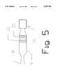
- FIG. 5is a view of a distal end or tip of a guide wire incorporating the invention and depicting a plurality of regions that have been heat treated for bending;
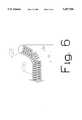
- FIG. 6is a view of a helical coil positioned as if attached to the distal end of the guide wire in FIG. 5 after multiple bending.
- FIG. 1discloses a partial plan view of a catheter guide wire 10.
- Guide wire 10is known in the prior art and is shown here as a preferred embodiment for the addition of the present invention.
- guide wire 10includes a distal end comprising a plurality of alternating steps of continuous and tapering diameters shown here as tapering steps 12, 14, 16 and 18 alternating with continuous steps 13, 15 and 17.
- the distal endsinclude a distal tip section 19 connected between step 18 and a tip connection member shown generally as 20.
- distal tip section 19is shown as a flattened ribbon and will be referred to hereafter as ribbon 19.
- Guide wire 10 of FIG. 1is preferably constructed of a metal that contains a high degree of resiliency. Though there are several such materials with a higher degree of resiliency than stainless steel, in this particular embodiment stainless steel 304V has been selected as the preferred metal. Stainless steel 304V is known to have an annealing point at approximately 1400° F.
- FIG. 2is a drawing of guide wire 10 with a helical coil 26 and a ball tip 28 shown attached to guide wire 10 in a manner well known in the prior art. Any portion of step 18, ribbon 19 and connection member 20 which may show through the coils of coil 26 have been omitted from FIG. 2 for purposes of clarity, though it is understood that some or all of these elements are covered by coil 26; the same deliberate omission will be made in all of the Figs. of the drawings for the same purpose.
- FIG. 2also shows a polymer sleeve 24 used in the preferred embodiment of this invention in a manner well known in the prior art to cover a portion of the distal segment of guide wire 10 and aid in the steerage of wire 10 through a body lumen.
- FIG. 3depicts distal tip section or ribbon 19 after a single sector, region or band 30 has been heat treated in accordance with the teachings of this invention.
- Region 30may not be visible to the eye and is therefore shown here as a hatched band so that the reader may best understand the invention.
- prior art catheter guide wiresoften had a metal ribbon at the distal end of the guide wires and typically used the ribbon to introduce or form a J-tip configuration. It is generally known that the force used to form or bend a non heat-treated ribbon could result in undesirable inconsistencies and irregularities. Heat treating the entire ribbon, e.g. to about 1400° F. for the stainless steel 304V used in the preferred embodiment of this invention, can result in adding too much formability to the distal tip section of the prior art guide wire thus decreasing its steerability through a lumen by reducing resiliency and tip strength. Similarly, the presently known practice of heating the distal section to a temperature of about 950° F. and then cold stamping the ribbon has been found to result in a guide wire tip with less than optimum performance.
- the improved guide wire 10 of this inventionas shown in FIG. 3, only a comparatively narrow region or band 30 on previously formed ribbon 19 is heat treated.
- the area of band 30 in ribbon 19is significantly less than the total area of ribbon 19.
- the resulting improved distal sectioncan be easily bent or formed into the desired J-tip, by the manufacturer or by the physician at the time of use, by bending the ribbon 19 at the area of band 30.
- the formingdoes not significantly affect the resiliency or flexibility of the remainder of ribbon 19 and improved guide wire steerability is achieved.
- the region 30is created by heat treating only the region 30 to a temperature above about 850° F. but less than 1400° F., and more preferably to a temperature of 950° F.
- This heat treatmentcould be accomplished by subjecting the region 30 to a laser for only a few seconds or to a fiber optic light system for approximately 30 seconds.
- conventional inductive or convective methods applied over several minutescould be used, however, these methods would be less accurate than the previously-mentioned methods.
- FIG. 4depicts the general shape of coil 26 after a bend has been made in ribbon 19 of FIG. 3 at region 30.
- Angle 35may be altered by the physician to suit the needs of the particular case at hand, and similarly the manufacturer may selectively use more than one set of angles 35.
- length 34is also a variable that is set by the location of heat treated band 30 in ribbon 19. Therefore, by varying the location of band 30, multiple lengths 34 and angles 35 can be obtained.
- FIG. 5depicts another preferred embodiment of this invention in which ribbon 19 carries a plurality of heat treated regions or bands here shown as 30 and 31.
- Reference to FIG. 6depicts, by way of example, a resulting J-tip formation that can be achieved with the embodiment of FIG. 5 utilizing more than a single heat treated sector on ribbon 19.
- Lengths 34 and 36are again dependent on the location of bands 30 and 31 in ribbon 19 and may be selected as desired for a particular guide wire 10.
- the physiciancould choose to form a single band similar to FIG. 4 by bending the wire at band 30 or band 31.
- the physicianis provided with a guide wire having a formable tip with multiple lengths 34.
Landscapes
- Health & Medical Sciences (AREA)
- Life Sciences & Earth Sciences (AREA)
- Biophysics (AREA)
- Pulmonology (AREA)
- Engineering & Computer Science (AREA)
- Anesthesiology (AREA)
- Biomedical Technology (AREA)
- Heart & Thoracic Surgery (AREA)
- Hematology (AREA)
- Animal Behavior & Ethology (AREA)
- General Health & Medical Sciences (AREA)
- Public Health (AREA)
- Veterinary Medicine (AREA)
- Media Introduction/Drainage Providing Device (AREA)
Abstract
Description
1. Field of the Invention
The present invention relates in general to medical instrumentation, and more particularly to intraluminal devices, and still more particularly to guide wires for intraluminal catheters.
2. Description of the Prior Art
The use of intraluminal catheters for treatment of various medical problems within the body is well known. It is also well known that a variety of problems are encountered as the catheter is steered through the selected lumen to a desired point in the body. The path may be tortuous and the point of interest may be difficult to locate precisely. A continuing series of technical improvements and additions have been made in the catheter field to provide devices and methods which can overcome certain of the difficulties. One such series of improvements has resulted in the now well known use of a thin flexible guide wire which can be more easily steered through the lumen to the desired site. A selected catheter, such as a balloon catheter, can then be slid over the guide wire to reach the desired situs in the body.
It is now well known that providing a bend or "J-tip" to the distal end of the guide wire increases maneuverability of the guide wire through the lumen. Such J-tips are often set by the manufacturer of the guide wire, but it is also sometimes advantageous to have the physician or other operator create or modify the bend during an angioplasty procedure.
Certain disadvantages exist in this known prior art. For example, the material most commonly used for guide wires is stainless steel, for example, 304V stainless steel. The formation of a bend or J-tip at the distal end of such a metal wire requires a force which may be inconsistent or irregular thus significantly effecting the strength of the guide wire tip. One way to attempt to increase formability of the guide wire distal end may be to heat the tip. In the present art, the tip is often heated prior to cold working, in the case of stainless steel 304V to a temperature within the range of 700° to 1000° F. This procedure of increasing temperature followed by cold working of the stainless steel results in a less than optimum performance. It is also likely that heating the entire distal portion of the guide wire to the annealing temperature, approximately 1400° F. in the case of stainless steel 304V, may add too much formability to the wire tip, thus negatively effecting its tip strength and steering properties as it is guided through a body lumen.
As a general example of formable tip references in the prior art, see by way of example, U.S. Pat. No. 4,846,186, issued Jul. 11, 1989 to Box, et al; and U.S. Pat. No. 4,838,879, issued Jun. 13, 1989 to Tanabe, et al.
The present invention overcomes the described disadvantages of the prior art by providing an apparatus and method for a catheter guide wire having one or more distinct regions at its distal end, which regions are heat treated to provide the desired properties of a formable material, and which regions are sufficiently limited so as not to substantially reduce the flexibility and resilience of the rest of the guide wire distal end. Thus the J-tip formation may be easily and consistently achieved without compromising the guide wire tip performance.
The objects and many of the attendant advantages of the present invention will be readily appreciated as it becomes better understood by reference to the following detailed description when considered in connection with the accompanying drawings, in which like reference numerals designate like parts throughout the figures thereof and wherein:
FIG. 1 is a plan view showing a prior art catheter guide wire;
FIG. 2 is a plan view showing the distal end of the prior art guide wire of FIG. 1 covered by a helical coil and a polymer sleeve;
FIG. 3 is a view of a distal end or tip of a guide wire incorporating the invention and depicting a single region that has been heat treated for bending;
FIG. 4 is a view of a helical coil positioned as if attached to the distal end of the guide wire in FIG. 3 after bending;
FIG. 5 is a view of a distal end or tip of a guide wire incorporating the invention and depicting a plurality of regions that have been heat treated for bending; and
FIG. 6 is a view of a helical coil positioned as if attached to the distal end of the guide wire in FIG. 5 after multiple bending.
FIG. 1 discloses a partial plan view of acatheter guide wire 10.Guide wire 10 is known in the prior art and is shown here as a preferred embodiment for the addition of the present invention. In addition to a proximal end 11, shown here in part,guide wire 10 includes a distal end comprising a plurality of alternating steps of continuous and tapering diameters shown here astapering steps 12, 14, 16 and 18 alternating withcontinuous steps 13, 15 and 17. The distal ends include adistal tip section 19 connected between step 18 and a tip connection member shown generally as 20. In this preferred embodimentdistal tip section 19 is shown as a flattened ribbon and will be referred to hereafter asribbon 19.
FIG. 2 is a drawing ofguide wire 10 with ahelical coil 26 and aball tip 28 shown attached to guidewire 10 in a manner well known in the prior art. Any portion of step 18,ribbon 19 andconnection member 20 which may show through the coils ofcoil 26 have been omitted from FIG. 2 for purposes of clarity, though it is understood that some or all of these elements are covered bycoil 26; the same deliberate omission will be made in all of the Figs. of the drawings for the same purpose. FIG. 2 also shows apolymer sleeve 24 used in the preferred embodiment of this invention in a manner well known in the prior art to cover a portion of the distal segment ofguide wire 10 and aid in the steerage ofwire 10 through a body lumen.
FIG. 3 depicts distal tip section orribbon 19 after a single sector, region orband 30 has been heat treated in accordance with the teachings of this invention.Region 30 may not be visible to the eye and is therefore shown here as a hatched band so that the reader may best understand the invention.
As described above, prior art catheter guide wires often had a metal ribbon at the distal end of the guide wires and typically used the ribbon to introduce or form a J-tip configuration. It is generally known that the force used to form or bend a non heat-treated ribbon could result in undesirable inconsistencies and irregularities. Heat treating the entire ribbon, e.g. to about 1400° F. for the stainless steel 304V used in the preferred embodiment of this invention, can result in adding too much formability to the distal tip section of the prior art guide wire thus decreasing its steerability through a lumen by reducing resiliency and tip strength. Similarly, the presently known practice of heating the distal section to a temperature of about 950° F. and then cold stamping the ribbon has been found to result in a guide wire tip with less than optimum performance.
In the improvedguide wire 10 of this invention as shown in FIG. 3, only a comparatively narrow region orband 30 on previously formedribbon 19 is heat treated. The area ofband 30 inribbon 19 is significantly less than the total area ofribbon 19. The resulting improved distal section can be easily bent or formed into the desired J-tip, by the manufacturer or by the physician at the time of use, by bending theribbon 19 at the area ofband 30. Yet, unlike the prior art, the forming does not significantly affect the resiliency or flexibility of the remainder ofribbon 19 and improved guide wire steerability is achieved.
In the preferred embodiment, theregion 30 is created by heat treating only theregion 30 to a temperature above about 850° F. but less than 1400° F., and more preferably to a temperature of 950° F. This heat treatment could be accomplished by subjecting theregion 30 to a laser for only a few seconds or to a fiber optic light system for approximately 30 seconds. Those skilled in the art would recognize that conventional inductive or convective methods applied over several minutes could be used, however, these methods would be less accurate than the previously-mentioned methods.
FIG. 4 depicts the general shape ofcoil 26 after a bend has been made inribbon 19 of FIG. 3 atregion 30.Angle 35 may be altered by the physician to suit the needs of the particular case at hand, and similarly the manufacturer may selectively use more than one set ofangles 35. Further,length 34 is also a variable that is set by the location of heat treatedband 30 inribbon 19. Therefore, by varying the location ofband 30,multiple lengths 34 andangles 35 can be obtained.
FIG. 5 depicts another preferred embodiment of this invention in whichribbon 19 carries a plurality of heat treated regions or bands here shown as 30 and 31. Reference to FIG. 6 depicts, by way of example, a resulting J-tip formation that can be achieved with the embodiment of FIG. 5 utilizing more than a single heat treated sector onribbon 19. Here there are shown dual bends incoil 26 the angles of each being separately selectable by the physician or manufacturer as described in the discussion of FIG. 4 above.Lengths bands 30 and 31 inribbon 19 and may be selected as desired for aparticular guide wire 10. In the alternative, the physician could choose to form a single band similar to FIG. 4 by bending the wire atband 30 or band 31. In this embodiment, the physician is provided with a guide wire having a formable tip withmultiple lengths 34.
Referring again to FIG. 5, it will be recognized that additional regions of heat treatment, such as 30 and 31, may be added as desired should a more complex J-tip configuration be desired. It is preferred that the total lengths, and thus the total area, of heat treated bands such as 30 and 31 be selected such that the total area of treated portions ofribbon 19 be less than the total area ofribbon 19. This will prevent the heat treatment from interfering with the resilience and flexibility of the distal tip section, shown asribbon 19, ofguide wire 10.
Having thus described the preferred embodiments of the present invention, those of skill in the art will readily appreciate the other useful embodiments within the scope of the attached claims.
Claims (9)
1. A guide wire apparatus comprising:
a. a length of flexible metal wire with proximal and distal ends;
b. a distal tip section at the distal end of the flexible metal wire; and
c. a heat-treated region on the distal tip section which has been heat treated to a temperature above about 850° but less than 1400° F., for providing an easily formable portion of the distal tip section, said heat treated region having an area substantially less than the area of the distal tip section.
2. A guide wire apparatus according to claim 1 further comprising a plurality of distinct heat-treated regions on the distal tip section for providing a plurality of easily formable portions of the distal tip section.
3. A guide wire apparatus according to claim 2 wherein the total area of the plurality of heat-treated regions is less than the area of the distal tip section.
4. A method of making a metal catheter guide wire with a formable tip comprising the steps of:
a. providing a flexible wire having proximal and distal ends and a metal portion at the distal end;
b. heat-treating a discrete region of the metal portion to a temperature above about 850° but less than 1400° F. to increase the ease of formability of the discrete region; and
c. attaching a coil to the distal end of the metal wire.
5. A method of making a metal catheter guide wire according to claim 4 wherein the heat treating step comprises heating a plurality of discrete regions of the metal portion.
6. A formable catheter guide wire apparatus comprising:
a. a length of flexible metal wire having proximal and distal ends;
b. a flexible coil attached to the wire such that at least a portion of the distal end is covered by the coil; and
c. a heat-treated region in the distal end of the wire, which has been heat treated to a temperature above about 850° but less than 1400° F., that is covered by the coil.
7. A guide wire apparatus according to claim 6 further comprising a plurality of separate heat-treated regions in the distal end of the wire that are covered by the coil.
8. A guide wire apparatus according to claim 6 wherein the heat-treated region has a length less than the length of the distal end.
9. A guide wire apparatus according to claim 7 wherein the plurality of heat-treated regions have a total length less than the length of the distal end.
Priority Applications (1)
| Application Number | Priority Date | Filing Date | Title |
|---|---|---|---|
| US08/292,533US5497786A (en) | 1994-08-18 | 1994-08-18 | Apparatus and method for formable guide wire tip |
Applications Claiming Priority (1)
| Application Number | Priority Date | Filing Date | Title |
|---|---|---|---|
| US08/292,533US5497786A (en) | 1994-08-18 | 1994-08-18 | Apparatus and method for formable guide wire tip |
Publications (1)
| Publication Number | Publication Date |
|---|---|
| US5497786Atrue US5497786A (en) | 1996-03-12 |
Family
ID=23125070
Family Applications (1)
| Application Number | Title | Priority Date | Filing Date |
|---|---|---|---|
| US08/292,533Expired - LifetimeUS5497786A (en) | 1994-08-18 | 1994-08-18 | Apparatus and method for formable guide wire tip |
Country Status (1)
| Country | Link |
|---|---|
| US (1) | US5497786A (en) |
Cited By (38)
| Publication number | Priority date | Publication date | Assignee | Title |
|---|---|---|---|---|
| EP0815894A1 (en) | 1996-06-28 | 1998-01-07 | Target Therapeutics | Fiber tip guidewire |
| US5788654A (en)* | 1995-07-18 | 1998-08-04 | Schneider (Europe) A.G. | Wedge-tipped catheter guidewire |
| US5895378A (en)* | 1997-05-29 | 1999-04-20 | Target Therapeutics, Inc. | Flow-directed catheter having multiple tapers and radio-opaque markers |
| US5957865A (en)* | 1997-09-25 | 1999-09-28 | Merit Medical Systems, Inc. | Flexible catheter guidewire |
| US20030114776A1 (en)* | 2001-12-18 | 2003-06-19 | Scimed Life Systems, Inc. | Guide wire with adjustable flexibility |
| US6673025B1 (en) | 1993-12-01 | 2004-01-06 | Advanced Cardiovascular Systems, Inc. | Polymer coated guidewire |
| US20040059259A1 (en)* | 1997-06-04 | 2004-03-25 | Advanced Cardiovascular Systems, Inc. | Guidewire having linear change in stiffness |
| US20040220499A1 (en)* | 2003-05-01 | 2004-11-04 | Scimed Life Systems, Inc. | Medical instrument with controlled torque transmission |
| US6832715B2 (en) | 2001-12-03 | 2004-12-21 | Scimed Life Systems, Inc. | Guidewire distal tip soldering method |
| US20080119762A1 (en)* | 2006-11-16 | 2008-05-22 | Tateishi Tadasu | Guide wire |
| US20080146967A1 (en)* | 1997-06-04 | 2008-06-19 | Richardson Mark T | Polymer coated guidewire |
| US20080154152A1 (en)* | 2006-12-26 | 2008-06-26 | Hideo Satou | Guide wire |
| US20080161726A1 (en)* | 2006-12-28 | 2008-07-03 | Yutaka Itou | Guide wire |
| US20080161727A1 (en)* | 2006-12-28 | 2008-07-03 | Youki Aimi | Guide wire |
| US20080171952A1 (en)* | 2007-01-12 | 2008-07-17 | Katsuro Mishima | Intermediate member, and a medical device and guide wire including such an intermediate member |
| US20080171217A1 (en)* | 2007-01-12 | 2008-07-17 | Katsuro Mishima | Brazing Material, Interventional Medical Device, and Joined Assembly |
| US20080173391A1 (en)* | 2000-12-28 | 2008-07-24 | Boston Scientific Scimed, Inc. | Method of manufacturing a guidewire with an extrusion jacket |
| US20080183182A1 (en)* | 2006-12-28 | 2008-07-31 | Hideo Satou | Guide wire |
| US20080234606A1 (en)* | 2007-03-23 | 2008-09-25 | Terumo Kabushiki Kaisha | Guide Wire |
| US20080255446A1 (en)* | 2007-04-16 | 2008-10-16 | General Electric Company | System and method of integrating electromagnetic microsensors in guidewires |
| US20080281396A1 (en)* | 2007-05-09 | 2008-11-13 | Japan Science And Technology Agency | Guide wire and stent |
| US20080281230A1 (en)* | 2007-05-11 | 2008-11-13 | Terumo Kabushiki Kaisha | Guide Wire |
| US7455646B2 (en) | 1997-06-04 | 2008-11-25 | Advanced Cardiovascular Systems, Inc. | Polymer coated guide wire |
| US20090157050A1 (en)* | 2007-03-29 | 2009-06-18 | Terumo Kabushiki Kaisha | Guide wire |
| US20090162530A1 (en)* | 2007-12-21 | 2009-06-25 | Orion Industries, Ltd. | Marked precoated medical device and method of manufacturing same |
| US20090181156A1 (en)* | 2007-12-21 | 2009-07-16 | Bruce Nesbitt | Marked precoated medical device and method of manufacturing same |
| US20090211909A1 (en)* | 2007-12-21 | 2009-08-27 | Bruce Nesbitt | Marked precoated medical device and method of manufacturing same |
| US20090326368A1 (en)* | 2008-06-30 | 2009-12-31 | General Electric Company | System and Method For Integrating Electromagnetic Microsensors in Guidewires |
| US7641622B2 (en) | 2007-02-09 | 2010-01-05 | Terumo Kabushiki Kaisha | Guide wire |
| US20100030112A1 (en)* | 2006-05-08 | 2010-02-04 | Cathrx Ltd | Shape imparting mechanism insertion |
| US7714217B2 (en) | 2007-12-21 | 2010-05-11 | Innovatech, Llc | Marked precoated strings and method of manufacturing same |
| US7828790B2 (en) | 2004-12-03 | 2010-11-09 | Boston Scientific Scimed, Inc. | Selectively flexible catheter and method of use |
| EP2417999A1 (en)* | 2010-08-10 | 2012-02-15 | Asahi Intecc Co., Ltd. | Guidewire with bent portion fixed with a fixing member |
| US8231926B2 (en) | 2007-12-21 | 2012-07-31 | Innovatech, Llc | Marked precoated medical device and method of manufacturing same |
| US20120227457A1 (en)* | 2008-03-10 | 2012-09-13 | Acclarent, Inc. | Corewire Design and Construction for Medical Devices |
| US8900652B1 (en) | 2011-03-14 | 2014-12-02 | Innovatech, Llc | Marked fluoropolymer surfaces and method of manufacturing same |
| US11452533B2 (en) | 2019-01-10 | 2022-09-27 | Abbott Cardiovascular Systems Inc. | Guide wire tip having roughened surface |
| US11951265B2 (en) | 2022-08-08 | 2024-04-09 | Embrace Medical Ltd | Vascular access wire tip comprising a crank |
Citations (10)
| Publication number | Priority date | Publication date | Assignee | Title |
|---|---|---|---|---|
| US4554929A (en)* | 1983-07-13 | 1985-11-26 | Advanced Cardiovascular Systems, Inc. | Catheter guide wire with short spring tip and method of using the same |
| US4682607A (en)* | 1985-12-02 | 1987-07-28 | Vlv Associates | Wire guide |
| US4832097A (en)* | 1988-06-27 | 1989-05-23 | Thomas Janice S | Basket weaving form |
| US4846186A (en)* | 1988-01-12 | 1989-07-11 | Cordis Corporation | Flexible guidewire |
| US4854330A (en)* | 1986-07-10 | 1989-08-08 | Medrad, Inc. | Formed core catheter guide wire assembly |
| US4951686A (en)* | 1985-02-26 | 1990-08-28 | B. Braun-Ssc Ag | Color marks on catheter guide wire |
| US4971490A (en)* | 1988-03-01 | 1990-11-20 | National Standard Company | Flexible guide wire with improved mounting arrangement for coil spring tip |
| US5069226A (en)* | 1989-04-28 | 1991-12-03 | Tokin Corporation | Catheter guidewire with pseudo elastic shape memory alloy |
| US5084022A (en)* | 1989-10-04 | 1992-01-28 | Lake Region Manufacturing Company, Inc. | Graduated guidewire |
| US5112136A (en)* | 1990-09-24 | 1992-05-12 | Kiyoshi Sakuma | Method of and apparatus for measuring thermal conductivity |
- 1994
- 1994-08-18USUS08/292,533patent/US5497786A/ennot_activeExpired - Lifetime
Patent Citations (10)
| Publication number | Priority date | Publication date | Assignee | Title |
|---|---|---|---|---|
| US4554929A (en)* | 1983-07-13 | 1985-11-26 | Advanced Cardiovascular Systems, Inc. | Catheter guide wire with short spring tip and method of using the same |
| US4951686A (en)* | 1985-02-26 | 1990-08-28 | B. Braun-Ssc Ag | Color marks on catheter guide wire |
| US4682607A (en)* | 1985-12-02 | 1987-07-28 | Vlv Associates | Wire guide |
| US4854330A (en)* | 1986-07-10 | 1989-08-08 | Medrad, Inc. | Formed core catheter guide wire assembly |
| US4846186A (en)* | 1988-01-12 | 1989-07-11 | Cordis Corporation | Flexible guidewire |
| US4971490A (en)* | 1988-03-01 | 1990-11-20 | National Standard Company | Flexible guide wire with improved mounting arrangement for coil spring tip |
| US4832097A (en)* | 1988-06-27 | 1989-05-23 | Thomas Janice S | Basket weaving form |
| US5069226A (en)* | 1989-04-28 | 1991-12-03 | Tokin Corporation | Catheter guidewire with pseudo elastic shape memory alloy |
| US5084022A (en)* | 1989-10-04 | 1992-01-28 | Lake Region Manufacturing Company, Inc. | Graduated guidewire |
| US5112136A (en)* | 1990-09-24 | 1992-05-12 | Kiyoshi Sakuma | Method of and apparatus for measuring thermal conductivity |
Cited By (89)
| Publication number | Priority date | Publication date | Assignee | Title |
|---|---|---|---|---|
| US6673025B1 (en) | 1993-12-01 | 2004-01-06 | Advanced Cardiovascular Systems, Inc. | Polymer coated guidewire |
| US5788654A (en)* | 1995-07-18 | 1998-08-04 | Schneider (Europe) A.G. | Wedge-tipped catheter guidewire |
| US5833631A (en)* | 1996-06-28 | 1998-11-10 | Target Therapeutics, Inc. | Fiber tip guidewire |
| EP0815894A1 (en) | 1996-06-28 | 1998-01-07 | Target Therapeutics | Fiber tip guidewire |
| US5895378A (en)* | 1997-05-29 | 1999-04-20 | Target Therapeutics, Inc. | Flow-directed catheter having multiple tapers and radio-opaque markers |
| US8308660B2 (en) | 1997-06-04 | 2012-11-13 | Advanced Cardiovascular Systems, Inc. | Guidewire having linear change in stiffness |
| US20040059259A1 (en)* | 1997-06-04 | 2004-03-25 | Advanced Cardiovascular Systems, Inc. | Guidewire having linear change in stiffness |
| US7494474B2 (en) | 1997-06-04 | 2009-02-24 | Advanced Cardiovascular Systems, Inc. | Polymer coated guidewire |
| US7455646B2 (en) | 1997-06-04 | 2008-11-25 | Advanced Cardiovascular Systems, Inc. | Polymer coated guide wire |
| US7878985B2 (en)* | 1997-06-04 | 2011-02-01 | Advanced Cardiovascular Systems, Inc. | Guidewire having linear change in stiffness |
| US7972283B2 (en) | 1997-06-04 | 2011-07-05 | Abbott Cardiovascular Systems Inc. | Guidewire having linear change in stiffness |
| US20090062773A1 (en)* | 1997-06-04 | 2009-03-05 | Advanced Cardiovascular Systems, Inc. | Guidewire having linear change in stiffness |
| US20080146967A1 (en)* | 1997-06-04 | 2008-06-19 | Richardson Mark T | Polymer coated guidewire |
| US5957865A (en)* | 1997-09-25 | 1999-09-28 | Merit Medical Systems, Inc. | Flexible catheter guidewire |
| US8535242B2 (en)* | 2000-12-28 | 2013-09-17 | Boston Scientific Scimed, Inc. | Method of manufacturing a guidewire with an extrusion jacket |
| US20130344230A1 (en)* | 2000-12-28 | 2013-12-26 | Boston Scientific Scimed, Inc. | Method of manufacturing a guidewire with an extrusion jacket |
| US8668657B2 (en)* | 2000-12-28 | 2014-03-11 | Boston Scientific Scimed, Inc. | Method of manufacturing a guidewire with an extrusion jacket |
| US20080173391A1 (en)* | 2000-12-28 | 2008-07-24 | Boston Scientific Scimed, Inc. | Method of manufacturing a guidewire with an extrusion jacket |
| US6832715B2 (en) | 2001-12-03 | 2004-12-21 | Scimed Life Systems, Inc. | Guidewire distal tip soldering method |
| US20030114776A1 (en)* | 2001-12-18 | 2003-06-19 | Scimed Life Systems, Inc. | Guide wire with adjustable flexibility |
| US20060127561A1 (en)* | 2001-12-18 | 2006-06-15 | Stephen Griffin | Guide wire with adjustable flexibility |
| US7918806B2 (en) | 2001-12-18 | 2011-04-05 | Boston Scientific Scimed, Inc. | Guide wire with adjustable flexibility |
| US7018346B2 (en) | 2001-12-18 | 2006-03-28 | Scimed Life Systems, Inc. | Guide wire with adjustable flexibility |
| US8845552B2 (en) | 2003-05-01 | 2014-09-30 | Boston Scientific Scimed, Inc. | Medical instrument with controlled torque transmission |
| US8292829B2 (en) | 2003-05-01 | 2012-10-23 | Boston Scientific Scimed, Inc. | Medical instrument with controlled torque transmission |
| US7780611B2 (en)* | 2003-05-01 | 2010-08-24 | Boston Scientific Scimed, Inc. | Medical instrument with controlled torque transmission |
| US20040220499A1 (en)* | 2003-05-01 | 2004-11-04 | Scimed Life Systems, Inc. | Medical instrument with controlled torque transmission |
| US8328791B2 (en) | 2004-12-03 | 2012-12-11 | Stryker Corporation | Selectively flexible catheter and method of use |
| US7828790B2 (en) | 2004-12-03 | 2010-11-09 | Boston Scientific Scimed, Inc. | Selectively flexible catheter and method of use |
| US20100030112A1 (en)* | 2006-05-08 | 2010-02-04 | Cathrx Ltd | Shape imparting mechanism insertion |
| US8977333B2 (en) | 2006-05-08 | 2015-03-10 | Cathrx Ltd | Shape-imparting mechanisms for catheter assemblies |
| AU2007247768B2 (en)* | 2006-05-08 | 2012-09-20 | Cathrx Ltd | Shape imparting mechanism insertion |
| EP2015825A4 (en)* | 2006-05-08 | 2010-08-04 | Cathrx Ltd | Shape imparting mechanism insertion |
| US20080119762A1 (en)* | 2006-11-16 | 2008-05-22 | Tateishi Tadasu | Guide wire |
| US7896820B2 (en) | 2006-12-26 | 2011-03-01 | Terumo Kabushiki Kaisha | Guide wire |
| US20080154152A1 (en)* | 2006-12-26 | 2008-06-26 | Hideo Satou | Guide wire |
| US20080161726A1 (en)* | 2006-12-28 | 2008-07-03 | Yutaka Itou | Guide wire |
| US20080161727A1 (en)* | 2006-12-28 | 2008-07-03 | Youki Aimi | Guide wire |
| US20080183182A1 (en)* | 2006-12-28 | 2008-07-31 | Hideo Satou | Guide wire |
| US7744545B2 (en) | 2006-12-28 | 2010-06-29 | Terumo Kabushiki Kaisha | Guide wire |
| US7637875B2 (en) | 2006-12-28 | 2009-12-29 | Terumo Kabushiki Kaisha | Guide wire |
| US7762962B2 (en) | 2007-01-12 | 2010-07-27 | Terumo Kabushiki Kaisha | Intermediate member, and a medical device and guide wire including such an intermediate member |
| US8206837B2 (en) | 2007-01-12 | 2012-06-26 | Terumo Kabushiki Kaisha | Interventional medical device |
| US20080171952A1 (en)* | 2007-01-12 | 2008-07-17 | Katsuro Mishima | Intermediate member, and a medical device and guide wire including such an intermediate member |
| US20080171217A1 (en)* | 2007-01-12 | 2008-07-17 | Katsuro Mishima | Brazing Material, Interventional Medical Device, and Joined Assembly |
| US7641622B2 (en) | 2007-02-09 | 2010-01-05 | Terumo Kabushiki Kaisha | Guide wire |
| US8172774B2 (en) | 2007-03-23 | 2012-05-08 | Terumo Kabushiki Kaisha | Guide wire |
| US20080234606A1 (en)* | 2007-03-23 | 2008-09-25 | Terumo Kabushiki Kaisha | Guide Wire |
| US20090157050A1 (en)* | 2007-03-29 | 2009-06-18 | Terumo Kabushiki Kaisha | Guide wire |
| US8128580B2 (en) | 2007-03-29 | 2012-03-06 | Terumo Kabushiki Kaisha | Guide wire |
| US20080255446A1 (en)* | 2007-04-16 | 2008-10-16 | General Electric Company | System and method of integrating electromagnetic microsensors in guidewires |
| US8239003B2 (en) | 2007-04-16 | 2012-08-07 | General Electric Company | System and method of integrating electromagnetic microsensors in guidewires |
| US8568470B2 (en) | 2007-05-09 | 2013-10-29 | Japan Science And Technology Agency | Guide wire and stent |
| US8052620B2 (en) | 2007-05-09 | 2011-11-08 | Japan Science And Technology Agency | Guide wire and stent |
| US20080281396A1 (en)* | 2007-05-09 | 2008-11-13 | Japan Science And Technology Agency | Guide wire and stent |
| US20080281230A1 (en)* | 2007-05-11 | 2008-11-13 | Terumo Kabushiki Kaisha | Guide Wire |
| US7753859B2 (en) | 2007-05-11 | 2010-07-13 | Terumo Kabushiki Kaisha | Guide wire |
| US20090211909A1 (en)* | 2007-12-21 | 2009-08-27 | Bruce Nesbitt | Marked precoated medical device and method of manufacturing same |
| US20090181156A1 (en)* | 2007-12-21 | 2009-07-16 | Bruce Nesbitt | Marked precoated medical device and method of manufacturing same |
| US8231926B2 (en) | 2007-12-21 | 2012-07-31 | Innovatech, Llc | Marked precoated medical device and method of manufacturing same |
| US10573280B2 (en) | 2007-12-21 | 2020-02-25 | Innovatech, Llc | Marked precoated strings and method of manufacturing same |
| US9782569B2 (en) | 2007-12-21 | 2017-10-10 | Innovatech, Llc | Marked precoated medical device and method of manufacturing same |
| US8048471B2 (en) | 2007-12-21 | 2011-11-01 | Innovatech, Llc | Marked precoated medical device and method of manufacturing same |
| US7923617B2 (en) | 2007-12-21 | 2011-04-12 | Innovatech Llc | Marked precoated strings and method of manufacturing same |
| US7811623B2 (en) | 2007-12-21 | 2010-10-12 | Innovatech, Llc | Marked precoated medical device and method of manufacturing same |
| US8772614B2 (en) | 2007-12-21 | 2014-07-08 | Innovatech, Llc | Marked precoated strings and method of manufacturing same |
| US8362344B2 (en) | 2007-12-21 | 2013-01-29 | Innovatech, Llc | Marked precoated strings and method of manufacturing same |
| US9355621B2 (en) | 2007-12-21 | 2016-05-31 | Innovatech, Llc | Marked precoated strings and method of manufacturing same |
| US7714217B2 (en) | 2007-12-21 | 2010-05-11 | Innovatech, Llc | Marked precoated strings and method of manufacturing same |
| US8574171B2 (en) | 2007-12-21 | 2013-11-05 | Innovatech, Llc | Marked precoated medical device and method of manufacturing same |
| US20090162530A1 (en)* | 2007-12-21 | 2009-06-25 | Orion Industries, Ltd. | Marked precoated medical device and method of manufacturing same |
| US8231927B2 (en) | 2007-12-21 | 2012-07-31 | Innovatech, Llc | Marked precoated medical device and method of manufacturing same |
| US8940357B2 (en) | 2007-12-21 | 2015-01-27 | Innovatech Llc | Marked precoated medical device and method of manufacturing same |
| US20100199830A1 (en)* | 2007-12-21 | 2010-08-12 | Innovatech, Llc | Marked precoated strings and method of manufacturing same |
| US20120227457A1 (en)* | 2008-03-10 | 2012-09-13 | Acclarent, Inc. | Corewire Design and Construction for Medical Devices |
| US9861793B2 (en)* | 2008-03-10 | 2018-01-09 | Acclarent, Inc. | Corewire design and construction for medical devices |
| US9002435B2 (en) | 2008-06-30 | 2015-04-07 | General Electric Company | System and method for integrating electromagnetic microsensors in guidewires |
| US20090326368A1 (en)* | 2008-06-30 | 2009-12-31 | General Electric Company | System and Method For Integrating Electromagnetic Microsensors in Guidewires |
| US8585613B2 (en)* | 2010-08-10 | 2013-11-19 | Asahi Intecc Co., Ltd. | Guidewire |
| CN102371024A (en)* | 2010-08-10 | 2012-03-14 | 朝日英达科株式会社 | Guidewire |
| US20120041420A1 (en)* | 2010-08-10 | 2012-02-16 | Asahi Intecc Co., Ltd. | Guidewire |
| EP2417999A1 (en)* | 2010-08-10 | 2012-02-15 | Asahi Intecc Co., Ltd. | Guidewire with bent portion fixed with a fixing member |
| US8900652B1 (en) | 2011-03-14 | 2014-12-02 | Innovatech, Llc | Marked fluoropolymer surfaces and method of manufacturing same |
| US9744271B2 (en) | 2011-03-14 | 2017-08-29 | Innovatech, Llc | Marked fluoropolymer surfaces and method of manufacturing same |
| US9962470B2 (en) | 2011-03-14 | 2018-05-08 | Innovatech, Llc | Marked fluoropolymer surfaces and method of manufacturing same |
| US10111987B2 (en) | 2011-03-14 | 2018-10-30 | Innovatech, Llc | Marked fluoropolymer surfaces and method of manufacturing same |
| US11452533B2 (en) | 2019-01-10 | 2022-09-27 | Abbott Cardiovascular Systems Inc. | Guide wire tip having roughened surface |
| US12137923B2 (en) | 2019-01-10 | 2024-11-12 | Abbott Cardiovascular Systems Inc. | Guide wire tip having roughened surface |
| US11951265B2 (en) | 2022-08-08 | 2024-04-09 | Embrace Medical Ltd | Vascular access wire tip comprising a crank |
Similar Documents
| Publication | Publication Date | Title |
|---|---|---|
| US5497786A (en) | Apparatus and method for formable guide wire tip | |
| EP0759793B1 (en) | Catheter guide wire with multiple radiopacity | |
| US6383146B1 (en) | Guidewire | |
| US6139557A (en) | Apparatus for making wire with radial expansible guide section and methods of manufacturing the same | |
| US4682607A (en) | Wire guide | |
| US5001825A (en) | Catheter guidewire fabrication method | |
| US6502606B2 (en) | Guidewire | |
| US4721117A (en) | Torsionally stabilized guide wire with outer jacket | |
| US8641697B2 (en) | Steerable catheter | |
| JP3616665B2 (en) | CATHETER HAVING SUPPRESSION MEMBER AND MANUFACTURING METHOD THEREOF | |
| US4934380A (en) | Medical guidewire | |
| US5497783A (en) | Guidewire having radioscopic tip | |
| US5368049A (en) | Superelastic formable guidewire with malleable cladding | |
| USRE34695E (en) | Torsionally stabilized guide wire with outer jacket | |
| EP0318046B1 (en) | Medical guidewire | |
| US5238004A (en) | High elongation linear elastic guidewire | |
| EP0340304B1 (en) | Guide wire for catheters and method of manufacturing same | |
| US20090018528A1 (en) | Method and apparatus for curving a catheter | |
| JP2004533271A (en) | Steerable guidewire and method of use | |
| JPH09127U (en) | Wire guide | |
| HK1002626B (en) | Formable guidewire | |
| JP4751553B2 (en) | Guiding aid | |
| CA2102250A1 (en) | Flexible catheter guidewire | |
| EP1469901A1 (en) | Guide wire | |
| EP0739641A1 (en) | Formable tip guidewire |
Legal Events
| Date | Code | Title | Description |
|---|---|---|---|
| AS | Assignment | Owner name:SCIMED LIFE SYSTEMS, INC., MINNESOTA Free format text:ASSIGNMENT OF ASSIGNORS INTEREST;ASSIGNOR:URICK, MICHAEL J.;REEL/FRAME:007128/0134 Effective date:19940818 | |
| STCF | Information on status: patent grant | Free format text:PATENTED CASE | |
| FPAY | Fee payment | Year of fee payment:4 | |
| FPAY | Fee payment | Year of fee payment:8 | |
| AS | Assignment | Owner name:BOSTON SCIENTIFIC SCIMED, INC., MINNESOTA Free format text:CHANGE OF NAME;ASSIGNOR:SCIMED LIFE SYSTEMS, INC.;REEL/FRAME:018505/0868 Effective date:20050101 Owner name:BOSTON SCIENTIFIC SCIMED, INC.,MINNESOTA Free format text:CHANGE OF NAME;ASSIGNOR:SCIMED LIFE SYSTEMS, INC.;REEL/FRAME:018505/0868 Effective date:20050101 | |
| FPAY | Fee payment | Year of fee payment:12 |