US5497339A - Portable apparatus for providing multiple integrated communication media - Google Patents
Portable apparatus for providing multiple integrated communication mediaDownload PDFInfo
- Publication number
- US5497339A US5497339AUS08/284,396US28439694AUS5497339AUS 5497339 AUS5497339 AUS 5497339AUS 28439694 AUS28439694 AUS 28439694AUS 5497339 AUS5497339 AUS 5497339A
- Authority
- US
- United States
- Prior art keywords
- communication
- data
- microcontroller
- interface
- pda
- Prior art date
- Legal status (The legal status is an assumption and is not a legal conclusion. Google has not performed a legal analysis and makes no representation as to the accuracy of the status listed.)
- Expired - Lifetime
Links
Images


Classifications
- G—PHYSICS
- G06—COMPUTING OR CALCULATING; COUNTING
- G06F—ELECTRIC DIGITAL DATA PROCESSING
- G06F15/00—Digital computers in general; Data processing equipment in general
- G06F15/02—Digital computers in general; Data processing equipment in general manually operated with input through keyboard and computation using a built-in program, e.g. pocket calculators
- G06F15/0225—User interface arrangements, e.g. keyboard, display; Interfaces to other computer systems
- G—PHYSICS
- G06—COMPUTING OR CALCULATING; COUNTING
- G06F—ELECTRIC DIGITAL DATA PROCESSING
- G06F1/00—Details not covered by groups G06F3/00 - G06F13/00 and G06F21/00
- G06F1/16—Constructional details or arrangements
- G06F1/1613—Constructional details or arrangements for portable computers
- G06F1/1626—Constructional details or arrangements for portable computers with a single-body enclosure integrating a flat display, e.g. Personal Digital Assistants [PDAs]
- G—PHYSICS
- G06—COMPUTING OR CALCULATING; COUNTING
- G06F—ELECTRIC DIGITAL DATA PROCESSING
- G06F1/00—Details not covered by groups G06F3/00 - G06F13/00 and G06F21/00
- G06F1/16—Constructional details or arrangements
- G06F1/1613—Constructional details or arrangements for portable computers
- G06F1/1632—External expansion units, e.g. docking stations
- H—ELECTRICITY
- H04—ELECTRIC COMMUNICATION TECHNIQUE
- H04M—TELEPHONIC COMMUNICATION
- H04M1/00—Substation equipment, e.g. for use by subscribers
- H04M1/72—Mobile telephones; Cordless telephones, i.e. devices for establishing wireless links to base stations without route selection
- H04M1/724—User interfaces specially adapted for cordless or mobile telephones
- H04M1/72403—User interfaces specially adapted for cordless or mobile telephones with means for local support of applications that increase the functionality
- H04M1/72409—User interfaces specially adapted for cordless or mobile telephones with means for local support of applications that increase the functionality by interfacing with external accessories
- G—PHYSICS
- G06—COMPUTING OR CALCULATING; COUNTING
- G06F—ELECTRIC DIGITAL DATA PROCESSING
- G06F2200/00—Indexing scheme relating to G06F1/04 - G06F1/32
- G06F2200/16—Indexing scheme relating to G06F1/16 - G06F1/18
- G06F2200/163—Indexing scheme relating to constructional details of the computer
- G06F2200/1632—Pen holder integrated in the computer
- H—ELECTRICITY
- H04—ELECTRIC COMMUNICATION TECHNIQUE
- H04M—TELEPHONIC COMMUNICATION
- H04M1/00—Substation equipment, e.g. for use by subscribers
- H04M1/72—Mobile telephones; Cordless telephones, i.e. devices for establishing wireless links to base stations without route selection
- H04M1/724—User interfaces specially adapted for cordless or mobile telephones
- H04M1/72403—User interfaces specially adapted for cordless or mobile telephones with means for local support of applications that increase the functionality
- H04M1/72406—User interfaces specially adapted for cordless or mobile telephones with means for local support of applications that increase the functionality by software upgrading or downloading
- H—ELECTRICITY
- H04—ELECTRIC COMMUNICATION TECHNIQUE
- H04M—TELEPHONIC COMMUNICATION
- H04M2250/00—Details of telephonic subscriber devices
- H04M2250/10—Details of telephonic subscriber devices including a GPS signal receiver
- H—ELECTRICITY
- H04—ELECTRIC COMMUNICATION TECHNIQUE
- H04M—TELEPHONIC COMMUNICATION
- H04M2250/00—Details of telephonic subscriber devices
- H04M2250/22—Details of telephonic subscriber devices including a touch pad, a touch sensor or a touch detector
- H—ELECTRICITY
- H04—ELECTRIC COMMUNICATION TECHNIQUE
- H04W—WIRELESS COMMUNICATION NETWORKS
- H04W64/00—Locating users or terminals or network equipment for network management purposes, e.g. mobility management
- H—ELECTRICITY
- H04—ELECTRIC COMMUNICATION TECHNIQUE
- H04W—WIRELESS COMMUNICATION NETWORKS
- H04W84/00—Network topologies
- H04W84/02—Hierarchically pre-organised networks, e.g. paging networks, cellular networks, WLAN [Wireless Local Area Network] or WLL [Wireless Local Loop]
- H04W84/04—Large scale networks; Deep hierarchical networks
- H04W84/042—Public Land Mobile systems, e.g. cellular systems
- H—ELECTRICITY
- H04—ELECTRIC COMMUNICATION TECHNIQUE
- H04W—WIRELESS COMMUNICATION NETWORKS
- H04W88/00—Devices specially adapted for wireless communication networks, e.g. terminals, base stations or access point devices
- H04W88/02—Terminal devices
Definitions
- the present inventionis in the field of portable communication devices for providing a computer with multiple integrated communication media, such as a phone modem, a cellular telephone, a packet radio and a Global Positioning System engine.
- the present inventionrelates to a portable multiple integrated communication device for a palm computer.
- the present inventionconnects to and interfaces with a PDA to dramatically increase the functional capabilities of the PDA.
- the present inventionadds multiple integrated communication media to the resources currently available to the PDA, while maintaining a compact, portable size.
- the combination of the present invention with a PDAcan be used to place or receive a cellular telephone call or a land line telephone call, to transmit or receive packet radio data, to obtain three-dimensional location data from the Global Positioning System (GPS) and to send or receive data over a telephone cellular link or over a land line using a built in phone modem.
- GPSGlobal Positioning System
- These added communication featuresgreatly enhance the utility of the PDAs.
- the combined PDA and multiple integrated communication deviceprovides a powerful processing device with convenient access to vast stores of information over a variety of possible media.
- the communication devicecomprises first and second communication circuits providing first and second differing modes of communication, a first generic emulator coupled to the first communication circuit and a second generic emulator coupled to the second communication circuit, a first interface unit coupled to the first generic emulator and a second interface unit coupled to the second generic emulator, and an application program.
- the application programaccesses the first interface unit to generate a first command to control the operation of the first communication circuit.
- the application programaccesses the second interface unit to generate a second command to control the operation of the second communication circuit.
- the first interface unitcommunicates the first command to the first generic emulator.
- the second interface unitcommunicates the second command to the second generic emulator.
- the first generic emulatorreformats the first command and communicates the first command to the first communication circuit.
- the second generic emulatorreformats the second command and communicates the second command to the second communication circuit.
- the first communication circuitexecutes the first command and the second communication circuit executes the second command.
- FIG. 1is a perspective view of a palm computer for use with the portable multiple integrated communication device of the present invention.
- FIG. 2is a perspective view of the communication device of the present invention.
- FIG. 3is a perspective view of a palm computer mounted inside the communication device of the present invention.
- FIG. 4is a general functional block diagram of a first embodiment of the communication device of the present invention, connected to a palm computer.
- FIG. 5is a more detailed functional block diagram of the serial interface between the microcontroller and the pair of serial ports of FIG. 4.
- FIG. 6is a more detailed functional block diagram of the phone modem interface of FIG. 4.
- FIG. 7is a more detailed functional block diagram of the GPS engine interface of FIG. 4.
- FIG. 8is a more detailed functional block diagram of the packet radio interface and the cellular telephone interface of FIG. 4.
- FIGS. 9A, 9B and 9Cillustrate a flow chart of a computer program executed by the microcontroller of FIG. 4.
- FIG. 10is a functional block diagram of a second embodiment of the communication device of the present invention connected to a palm computer that has been programmed to implement an improved interface with the communication device.
- FIG. 11is a functional block diagram of the application server of FIG. 10.
- FIG. 12is a functional block diagram of the software of the communication server of FIG. 10.
- FIG. 13is a functional block diagram of the hardware of the communication server of FIG. 10.
- FIG. 14is a functional block diagram of the interconnections between the cellular telephone, the phone modem, the microphone and earphone jack and the phone jack of the second embodiment.
- FIGS. 15A, 15B, and 15Cillustrate a flow chart of the method implemented by the arbitrator of FIG. 11.
- FIG. 1illustrates a palm computer or personal digital assistant (PDA) 102 for use with the present invention.
- the PDA 102comprises an LCD display 78, a light pen 76, a DC power connector 50 and a serial interface connector 52.
- the PDA 102provides an operator with a variety of data processing and data storage functions in a lightweight, portable device.
- FIGS. 2 to 9Cillustrate a first embodiment 100 of the portable multiple integrated communication device of the present invention.
- FIG. 2illustrates a perspective view of the communication device 100.
- the communication device 100comprises a fixed securing surface 56, a supporting surface 57, a movable securing surface 58, a GPS antenna 123 (FIG. 7), either a cellular telephone antenna 121 (FIG. 8) or a packet radio antenna 122, a microphone and earphone jack 132, a serial/power interface connector 60, a serial/power interface cable 62, a phone jack 118, a pass-thru serial interface connector 68, a DC power connector 70 and a set of three LEDs 71, 72 and 73.
- the LEDs 71, 72 and 73indicate a low battery, power-on and packet radio transmit condition.
- FIG. 3illustrates the PDA 102 of FIG. 1 inserted into the communication device 100 of FIG. 2.
- the PDA 102is inserted into the communication device 100 by pressing the bottom end of the PDA 102 against the securing surface 58 to rotate the securing surface 58 toward its open position (shown by the phantom lines in FIG. 2) until the top end of the PDA 102 clears the fixed securing surface 56, lowering the PDA 102 against the supporting surface 57, with the orientation of FIG. 3.
- the PDA 102is then released, and a spring (not shown) rotates the securing surface 58 to its closed position, as shown by the solid lines in FIGS. 2 and 3, pressing the top end of the PDA 102 against the securing surface 56.
- the remote serial/power interface connector 60 of the communication device 100is inserted into both the DC power connector 50 and the serial interface connector 52 of the PDA 102.
- the combination of the PDA 102 and the communication device 100forms a small, lightweight unit that is convenient to carry around and to use.
- the structure of the communication device 100is preferably designed to allow access to connectors and controls of the PDA 102.
- the securing surface 56 of the communication device 100preferably has an opening corresponding to a slot in the top end of the SharpTM Expert PadTM, for insertion of an IC card into the slot of the Expert PadTM.
- the packet radio antenna 122 and the cellular telephone antenna 121 (shown in FIG. 8) of the communication device 100are preferably mounted so that they can be rotated between an active position and an inactive position. In the active position, the antenna 122 or 123 is generally perpendicular to the main structure of the communication device 100, as shown in FIG. 3, to achieve optimal reception.
- the antenna 122 or 123is adjacent to a side of the communication device 100 that is directly opposite the side with the phone jack 118.
- the GPS antenna 123may be mounted on the frame of the communication device 100, or it may be a separate device.
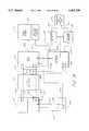
- FIG. 4illustrates a general functional block diagram of the first embodiment of the portable multiple integrated communication device 100 of the present invention, connected to a PDA 102.
- the communication device 100comprises a primary serial port 106, a buffer 108, a pass-thru serial port 110, a DC power connector 148, a power supply 146, a power connector 144, a microcontroller 104, a read-only memory (ROM) 134, a lamp 135, a decoder/multiplexer 112, a phone modem 114, a Data Access Arrangement (DAA) 116, the phone jack 118, a Global Positioning System (GPS) engine 120, the GPS antenna 123, either a packet radio 124 or a cellular telephone 126, a microphone amplifier 128, an earphone amplifier 130, the microphone and earphone jack 132, and either the packet radio antenna 122 or the cellular telephone antenna 121.
- GPSGlobal Positioning System
- the decoder/multiplexer 112comprises a dual 1:4 decoder or demultiplexer 136 and a dual 4:1 multiplexer or selector 138.
- the communication device 100comprises either the packet radio 124 or the cellular telephone 126, but not both.
- the circuit card implementing the packet radio 124occupies the same physical space inside the communication device 100 as the circuit card implementing the cellular telephone 126, thus conserving space and reducing the size of the communication device 100.
- the microcontroller 104preferably comprises an Intel® 80C320 microcontroller, although numerous other processors could be used.
- the microcontroller 104communicates with the PDA 102 through the primary serial port 106.
- the serial/power interface cable 62 of FIGS. 2 and 3is connected to the primary serial port 106 and the power connector 144 of FIG. 4.
- the primary serial port 160is used for the communication of commands and data between the microcontroller 104 and the PDA 102, as well as for the downloading of program code from the ROM 134 to the PDA 102.
- the power connector 144provides DC power from the power supply 146 to the PDA 102.
- the power supply 146also provides DC power to circuitry in the communication device 100.
- the power supply 146preferably comprises batteries.
- DC powercan also be provided by an external source through the DC power connector 148 to the power supply 146.
- the microcontroller 104can cause the power supply 146 to power down, either as a result of a command from the PDA 102 or after a period of inactivity, to conserve battery power.
- the communication device 100also has the separate pass-thru serial port 110 to allow other external devices to communicate with the PDA 102. Such devices may include printers, phone modems or an AppletalkTM network.
- the pass-thru serial port 110is connected to the pass-thru serial interface connector 68 of FIGS. 2 and 3.
- the buffer 108is used to enable or disable the serial port 110.
- the buffer 108comprises an LTC1032 component. If the microcontroller 104 needs to transmit data to the PDA 102 or receive data from the PDA 102, the microcontroller 102 disables the buffer 108. Otherwise, the buffer 108 is enabled to allow an external device to communicate with the PDA 102 through the serial port 110 and the primary serial port 106.
- the serial interfaces between the microcontroller 104, the PDA 102 and external devicesare described in greater detail below with reference to FIG. 5.
- the ROM 134comprises a 27C1001 128Kx8 ultraviolet erasable EPROM from NEC, or the like, in the first embodiment.
- the ROM 134contains code for both the microcontroller 104 and the PDA 102.
- the ROM 134may also contain code for standard external devices.
- the microcontroller 104executes code in the ROM 134 to implement the described functions of the communication device 100.
- the microcontroller 104also uploads code from the ROM 134 through the primary serial port 106 into the PDA 102.
- the PDA 102executes this code to provide an interface with the microcontroller 104 and to support and control the functions of the communication device 100.
- an operator of the combined PDA 102 and the communication device 100can utilize the functions provided by both the PDA 102 and the communication device 100 by providing appropriate input commands to the PDA 102.
- the PDA 102sends appropriate commands and data to the microcontroller 104 to control the functions of the communication device 100, as provided by the code in the ROM 134.
- the program executed by the microcontroller 104is described in greater detail below with reference to FIG. 9.
- the microcontroller 104can also download code to attached external devices.
- the first embodiment of the communication device 100provides the PDA 102 with access to three different communication media through the microcontroller 104 and the decoder/multiplexer 112.
- the communication mediainclude the phone modem 114, the GPS engine 120, and either the packet radio 124 or the cellular telephone 126.
- Each of the communication mediais implemented in a separate communication circuit.
- the decoder/multiplexer 112comprises a dual 1-to-4 decoder 136 and a dual 4-to-1 multiplexer 138.
- the decodercomprises a 74HC139 from Texas Instruments, or the like, while the multiplexer 138 comprises a 74HC153, also from Texas Instruments, or the like.
- the communication device 100has a separate serial interface from the microcontroller 104, through the decoder/multiplexer 112 to each of the communication circuits 114,120, 124 and 126.
- the microcontroller 104generates a single handshake signal and a single data signal to the decoder 136.
- the decoder 136has four pairs of handshake and data outputs (output pair A, output pair B, output pair C and output pair D), to which the signals from the microcontroller 104 may be connected.
- the microcontroller 104generates a pair of select signals on a pair of select lines 140 and 142 to the decoder 136.
- the two select signalshave logical values of 00, 01, 10, or 11 to control the selection of one of the four output pairs of the decoder 136 to which the input pair is connected.
- the output pair Ais connected to both the packet radio 124 and the cellular telephone 126; however, as discussed above, only one of the two devices is installed at any particular time in the present embodiment.
- the output pair Bhas only one line which is connected to the GPS engine 120.
- the output pair Cis connected to the phone modem 114.
- the output pair Dis unconnected in the present embodiment.
- the microcontroller 104can send serial data to any of the installed communication circuits 114, 120 and either 124 or 126 by selecting the appropriate select signals.
- the phone modem 114also generates a handshake signal and a data signal for a serial interface which is connected to an input pair C on the multiplexer 138.
- the GPS engine 120also generates a handshake signal and a data signal for a serial interface that is connected to an input pair B on the multiplexer 138.
- the packet radio 124also generates a handshake signal and a data signal for a serial interface that is connected to an input pair A on the multiplexer 138.
- the cellular telephone 126also generates a handshake signal and a data signal for a serial interface that is also connected to the input pair A on the multiplexer 138.
- the multiplexer 138also has an output pair to which one of four input pairs is internally connected.
- This output pair of the multiplexer 138is connected to the microcontroller 104.
- the microcontroller 104controls the selection of the multiplexer 138 using the same select signals as described above with reference to the decoder 136.
- the microcontroller 104can select an input pair to receive the serial interface signals from a selected one of the installed communication circuits 114, 120 and either 124 or 126.
- the select lines from the microcontroller 104are preferably connected to the decoder 136 and the multiplexer 138 so that the communication circuit 114, 120, 124 or 126 selected by the decoder 136 is also selected by the multiplexer at all times.
- the microcontroller 104by controlling the select lines to select input pair C and output pair C, the microcontroller 104 generates a handshake and a data signal for a serial interface that is received by the phone modem 114.
- the microcontroller 104can also receive a handshake and a data signal for a serial interface that are generated by the phone modem 114.
- the decoder/multiplexer 112allows the microcontroller 104 to select between three different serial interfaces.
- a first serial interfaceallows the microcontroller 104 to communicate with the phone modem 114 and is described in greater detail below with reference to FIG. 6.
- a second serial interfaceallows the microcontroller 104 to communicate with the GPS engine 120 and is described in greater detail below with reference to FIG. 7.
- a third serial interfaceallows the microcontroller 104 to communicate with either the packet radio 124 or the cellular telephone 126 and is described in greater detail below with reference to FIG. 8.
- FIG. 5is a more detailed functional block diagram of the serial interface between the microcontroller 104, the primary serial port 106 and the pass-thru serial port 110, shown in FIG. 4.
- the microcontroller 104is connected to the primary serial port 106 and to the buffer 108 by a transmit data line 202, a handshake-in line 204, a handshake-out line 208 and a receive data line 210.
- the microcontroller 104is connected to an output port 200 by a set of three address lines 228, a data line 230 and a write enable line 232.
- the output port 200is connected to the primary serial port 106 and the serial port 110 by a GPI line 206.
- the output port 200is connected to the buffer 108 by a receive enable line 224 and a transmit enable line 226.
- the buffer 108is connected to the serial port 110 by a differential pair of transmit data lines 212 and 214, a handshake-out line 216, a handshake-in line 218, and a differential pair of receive data lines 220 and 222.
- the microcontroller 104receives an active low signal from the primary serial port 106 on the transmit data line 202 and another signal from the primary serial port 106 on the handshake-out line 208.
- the microcontroller 104also generates an active low signal to the primary serial port 106 on the transmit data line 210 and another signal to the primary serial port 106 on the handshake-in line 204.
- a person of skill in the artwill understand the use of these handshake and data signals to form a serial interface between the microcontroller 104 and the primary serial port 106.
- a serial port of a PDA 102is connected to the primary serial port 106, so that the microcontroller 104 can communicate with the PDA 102 over the serial interface.
- the output port 200constitutes an eight-bit addressable latch, such as a 74HC259 from Texas Instruments, or the like.
- the output port 200generates eight output data signals, three of which are applied to the receive enable line 224, the transmit enable line 226 and the GPI line 206, respectively. Other output signals of the output port 200 are described below with reference to FIGS. 6, 7 and 8.
- the output port 200also receives signals on the set of three address lines 228 for selecting among the eight output signals. It also receives signals on the data line 230 and on the write enable line 232.
- the microcontroller 104writes data to the output port 200 one bit at a time by controlling the address lines 228, the input data line 230 and the write enable line 232.
- the output port 200decodes the signals on the address lines 228 to determine which output signal is written. When the signal on the write enable line 232 is activated, the output port 200 transfers the logic level at the input data line 230 to the corresponding output data signal.
- the GPI line 206is connected to both the primary serial port 106 and the serial port 110.
- the PDA 102can receive a pulse on the GPI line 206 from either the microcontroller 104 through the output port 200 or from an external device through the serial port 110.
- the PDA 102Upon receiving a pulse on the GPI line 206, if the PDA 102 has gone into a sleep mode to conserve battery power, the PDA 102 "wakes up" and becomes fully operational. Either the microcontroller 104 or an external device can wake up the PDA 102 at any time. If the PDA 102 is not in a sleep mode when a pulse is received on the GPI line 206, the pulse will operate as an interrupt to the PDA 102.
- the GPI line 206can be used to allow the microcontroller 104 to wake up an external device. Thus, if an external device is in a sleep mode, the external device can be activated by receiving a pulse on the GPI line 206 from the microcontroller 104.
- the transmit data line 202carries an active low TTL signal from the primary serial port 106 to the buffer 108.
- the buffer 108transforms the TTL signal on the transmit data line 202 to a differential signal on the transmit data lines 212 and 214.
- the transmit data lines 212 and 214are connected between the buffer 108 and the serial port 110.
- the handshake-out line 208carries the handshake-out signal from the primary serial port 106 to the buffer 108.
- the buffer 108generates a signal on the handshake-out line 216 in response to the signal on the handshake-out line 208.
- the handshake-out line 216is connected between the buffer 108 and the serial port 110.
- the output port 200generates a signal on the transmit enable line 226, which is connected to the buffer 108.
- This signalenables or disables the gates in the buffer 108 that generate the signals on the transmit data lines 212 and 214 and on the handshake-out line 216.
- the serial port 110receives the active low transmit data signal and the handshake-out signal from the primary serial port 106 only if the signal on the transmit enable line 228 is active.
- the external deviceapplies a signal through the serial port 110 to the handshake-in line 218.
- the handshake-in line 218is connected between the serial port 110 and the buffer 108.
- the buffer 108generates a signal on the handshake-in line 204 in response to the signal on the handshake-in line 218.
- the handshake-in line 204is connected between the buffer 108 and the primary serial port 106. If an external device is connected to the serial port 110, the external device generates a differential signal through the serial port 110 to the receive data lines 220 and 222.
- the receive data lines 220 and 222are connected between the serial port 110 and the buffer 108.
- the buffer 108generates a TTL signal on the receive data line 210 in response to the differential signal on the receive data lines 220 and 222.
- the output port 200generates a signal on the receive enable line 224, which is connected to the buffer 108. This signal enables or disables the gates in the buffer 108 that generate the signals on the handshake-in line 204 and on the receive data line 210.
- the microcontroller 104can determine whether the handshake-in signals and the receive data signals from an external device are communicated through to the primary serial port 106.
- a person of skill in the artwill understand the operation of the handshake and data signals between the serial port 110 and the primary serial port 106 for providing a serial interface between an external device and the PDA 102.
- the microcontroller 104If the microcontroller 104 needs to use the serial interface between the microcontroller 104 and the PDA 102, the microcontroller 104 causes the signals on the transmit enable line 226 and on the receive enable line 224 to become inactive. This disables the serial interface between the external device at the serial port 110 and the PDA 102 at the primary serial port 106. Whenever the microcontroller 104 does not need to use the serial interface with the PDA 102, the microcontroller 104 sets the signals on the transmit enable line 226 and on the receive enable line 224 to active levels. This enables the buffer 108 and the serial interface between the external device at the serial port 110 and the PDA 102 at the primary serial port 106.
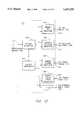
- FIG. 6is a more detailed functional block diagram of the interface between the microcontroller 104 and the phone modem 114.
- This interfacecomprises the microcontroller 104, the decoder/multiplexer 112, the phone modem 114, the DAA 116, the phone jack 118, the output port 200, a sound transducer 330, a lightning suppressor 300, the set of three address lines 228, the data line 230, the write enable line 232, a set of two handshake-out lines 302 and 310, a set of two transmit data lines 304 and 312, a set of two handshake-in lines 306 and 314, a set of two receive data lines 308 and 316, a transmit line 318, a receive line 320, an off-hook line 322, a set of two ring indicator lines 324 and 332, a tip line 326, a ring line 328, an audio line 336 and an enable modem line 334.
- the microcontroller 104generates signals on the handshake-out line 302 and on the transmit data line 304.
- the microcontroller 104also receives signals on the handshake-in line 306 and on the receive data line 308.
- the handshake-out line 302, the transmit data line 304, the handshake-in line 306 and the receive data line 308are connected between the microcontroller 104 and the decoder/multiplexer 112. As described above with reference to FIG.
- the decoder/multiplexer 112transfers the signal on the handshake-out line 302 to the handshake-out line 310; it transfers the signal on the transmit data line 304 to the transmit data line 312; it transfers a signal on the handshake-in line 314 to the handshake-in line 306; and it transfers a signal on the receive data line 316 to the receive data line 308.
- the handshake-out line 310is connected between the decoder/multiplexer 112 and a ready-to-send input of the phone modem 114.
- the transmit data line 312is connected between the decoder/multiplexer 112 and a transmit data input of the phone modem 114.
- the handshake-in line 314is connected between a clear-to-send output of the phone modem 114 and the decoder/multiplexer 112.
- the receive data line 316is connected between a receive data output of the phone modem 114 and the decoder/multiplexer 112.
- the handshake-out lines 302, 310, the transmit data lines 304, 312, the handshake-in lines 306, 314 and the receive data lines 308, 316form a serial interface between the microcontroller 104 and the phone modem 114.
- the phone modem 114comprises a Rockwell SM224ATF single-chip modem. This phone modem 114 can perform standard facsimile and modem functions and is controlled using a standard Hayes® compatible protocol. In an alternative embodiment, the phone modem 114 also generates and receives a pair of analog audio signals. These audio signals can be applied to lines connected between the phone modem 114 and the cellular telephone 126. In this alternative embodiment, information can be transferred between the cellular telephone 126 and the microcontroller 104 and between the cellular telephone 126 and the phone modem 114.
- the transmit line 318, the receive line 320, the off-hook line 322 and the ring indicator line 324,are connected between the phone modem 114 and the DAA 116.
- the phone modem 114applies data to the transmit line 318, while the DAA 116 applies received data to the receive line 320.
- the DAA 116activates a signal on the ring indicator line 324 to alert the phone modem 114 to an incoming phone call.
- the phone modem 114activates the signal on the off-hook line 322 to cause the DAA 116 to activate the telephone connection.
- a person of skill in the artwill understand the operation of the interface between the phone modem 114 and the DAA 116, as well as the operation of the DAA 116.
- the ring indicator line 332is connected between the phone modem 114 and the microcontroller 104.
- the phone modem 114activates a signal on the ring indicator line 332 in response to an active signal on the ring indicator line 324 from the DAA 116.
- the microcontroller 104receives the signal on the ring indicator line 332 at a modem ring indicator input of the microcontroller 104.
- the modem enable line 334is connected between a DTR input of the phone modem 114 and one of the eight output signals generated by the output port 200. As described above, the microcontroller 104 controls the output signals of the output port 200 by controlling the set of three address lines 228, the data line 230 and the write enable line 232.
- the microcontroller 104activates the signal on the modem enable line 334 to enable the phone modem 114 to send or receive data.
- the audio line 336is connected between the phone modem 114 and the sound transducer 330.
- the phone modem 114generates a signal on the audio line 336 to activate the sound transducer 330 to provide audio indicators to the user of the PDA 102.
- the tip line 326 and the ring line 328are each connected between the DAA 116, the phone jack 118 and the surge suppressor 300.
- the lightning suppressor 300protects the DAA 116 from voltage spikes on the telephone lines caused by lightning.
- the phone jack 118is mounted at an outside surface of the communication device 100, as illustrated in FIGS. 2 and 3.
- FIG. 7is a more detailed functional block diagram of the interface between the microcontroller 104 and the GPS engine 120.
- This interfacecomprises the microcontroller 104, the decoder/multiplexer 112, the GPS engine 120, the GPS antenna 123, the output port 200, the set of three address lines 228, the data line 230, the write enable line 232, the transmit data line 304, a transmit data line 400, the handshake-in line 306, a handshake-in line 402, the receive data line 308, a receive data line 404, a GPS antenna line 406 and an enable GPS line 408.
- the microcontroller 104generates a signal on the transmit data line 304, which is connected between the microcontroller 104 and the decoder/multiplexer 112.
- the microcontroller 104also receives signals on the handshake-in line 306 and on the receive data line 308, which are also connected between the microcontroller 104 and the decoder/multiplexer 112.
- the decoder/multiplexer 112transfers the signal on the transmit data line 304 to the transmit data line 400; it transfers a signal on the handshake line 402 to the handshake-in line 306; and it transfers a signal on the receive data line 404 to the receive data line 308.
- the transmit data line 400is connected between the decoder/multiplexer 112 and a transmit data input of the GPS engine 120.
- the handshake-in line 402is connected between a time mark output of the GPS engine 120 and the decoder/multiplexer 112.
- the receive data line 404is connected between a receive data output of the GPS engine 120 and the decoder/multiplexer 112.
- the GPS engine 120comprises a Rockwell NavCore® VI MicroTrackerTM Global Positioning System circuit card.
- the GPS engine 120receives commands from the microcontroller 104 over the transmit data lines 304 and 400.
- the microcontroller 104can use these commands to control a number of aspects of the operation of the GPS engine 120, such as a selection of the satellites utilized for computing the location of the communication device 100 and the frequency at which the GPS engine 120 makes this computation.
- the GPS antenna 123receives electromagnetic signals transmitted from GPS satellites.
- the GPS antenna 123applies these signals to the GPS antenna line 406 connected between the GPS antenna 123 and the GPS engine 120.
- the GPS engine 120utilizes the signals received from the satellites to calculate the location of the communication device 100 in terms of longitude, latitude and altitude.
- the GPS enable line 408is connected between the output port 200 and the GPS engine 120.
- the output port 200applies one of its eight output signals to the GPS enable line 408.
- the microcontroller 104controls the GPS enable line 408 by controlling the set of three address lines 228, the data line 230 and the write enable line 232.
- the microcontroller 104enables the GPS engine 120 to send commands to the GPS engine 120 or receive data back from the GPS engine 120.
- FIG. 8is a more detailed functional block diagram of the interface between the microcontroller 104 and either the packet radio 124 or the cellular telephone 126, whichever communication circuit is inserted.
- This interfacecomprises the microcontroller 104, the decoder/multiplexer 112, the packet radio 124, the cellular telephone 126, the packet radio antenna 122, the cellular telephone antenna 121, the microphone amplifier 128, the earphone amplifier 130, the microphone and earphone jack 132, the output port 200, the set of three address lines 228, the data line 230, the write enable line 232, the handshake-out line 302, a handshake-out line 500, the transmit data line 304, a transmit data line 502, the handshake-in line 306, a handshake-in line 504, the receive data line 308, a receive data line 506, a packet radio antenna line 508, a ring indicator line 510, a cellular telephone antenna line 514, a cellular telephone/packet radio enable line 512, a set of two microphone audio lines
- the microcontroller 104generates signals on the handshake-out line 302 and on the transmit data line 304, which are connected between the microcontroller 104 and the decoder/multiplexer 112.
- the microcontroller 104also receives signals on the handshake-in line 306 and on the receive data line 308, which are also connected between the microcontroller 104 and the decoder/multiplexer 112. As described above with reference to FIG.
- the decoder/multiplexer 112transfers the signal on the handshake-out line 302 to the handshake-out line 500; it transfers the signal on the transmit data line 304 to the transmit data line 502; it transfers a signal on the handshake-in line 504 to the handshake-in line 306; and it transfers a signal on the receive data line 506 to the receive data line 308.
- the handshake-out line 500is connected between the decoder/multiplexer 112 and a ready-to-send input of the packet radio 124.
- the transmit data line 502is connected between the decoder/multiplexer 112 and a transmit data input of the packet radio 124 or a DTMS input of the cellular telephone 126.
- the handshake-in line 504is connected between a clear-to-send output of the packet radio 124 or an SWDC5 output of the cellular telephone 126 and the decoder/multiplexer 112.
- the receive data line 506is connected between a receive data output of the packet radio 124 or a DFMS output of the cellular telephone 126 and the decoder/multiplexer 112.
- the handshake-out lines 302, 500, the transmit data lines 304,502, the handshake-in lines 306,504 and the receive data lines 308, 506form a serial interface between the microcontroller 104 and either the packet radio 124 or the cellular telephone 126.
- the packet radio 124comprises a GE/Ericson Moby Pack.
- the packet radio 124is connected to the antenna 122 by the packet radio line 508.
- the microcontroller 104sends control commands and packets of data to the packet radio 124 over the above-described serial interface.
- the packet radio 124generates a signal on the antenna line 508 to the antenna 122 to transmit the data to a base unit, as is well-known in the art.
- the antenna 122also receives data from base units and applies the data to the antenna line 508.
- the packet radio 124receives this data and relays the data to the microcontroller 104 over the above-described serial interface.
- the packet radio 124When the packet radio 124 initially receives data from a remote source, the packet radio 124 activates a ring indicator output signal.
- the ring indicator output signalis applied to the ring indicator line 510 connected between the packet radio 124 and the microcontroller 104. This signal alerts the microcontroller 104 to receive the incoming data.
- the cellular telephone/packet radio enable line 512is connected between the output port 200 and a DTR input of the packet radio 124 or an ON SRQ input of the cellular telephone 126.
- the DTR input of the packet radio 124is active low, while the ON SRQ input of the cellular telephone 126 is active high.
- the signal on the cellular telephone/packet radio enable line 512is low, the packet radio 124 is enabled and the cellular telephone 126 is disabled.
- the signalis high, the packet radio 124 is disabled and the cellular telephone 126 is enabled.
- the microcontroller 104it is necessary for the microcontroller 104 to send the correct enable signal to whichever communication circuit (either the packet radio 124 or the cellular telephone 126) is installed in order to activate the installed circuit.
- This signalis one of the eight output signals of the output port 200. As described above, the microcontroller 104 can control this signal by controlling the set of address lines 228, the data line 230 and the write enable line 232. Thus, the microcontroller 104 can enable the desired communication circuit 124 or 126.
- the cellular telephone 126comprises a GE/Ericson Mary Beth circuit card.
- the microphone and earphone jack 132is mounted at an outside surface of the communication device 100, as illustrated in FIGS. 2 and 3.
- An external microphone and earphone setcan be plugged into the microphone and earphone jack 132 to allow a telephone conversation between the user of the PDA 102 and a remote party, using the cellular telephone 126.
- the external microphoneapplies an audio signal to the audio line 522, through the microphone and earphone jack 132.
- the audio line 522is connected between the earphone amplifier 128 and the microphone and earphone jack 132.
- the microphone amplifier 128receives the signal on the audio line 522 and amplifies the signal to generate a signal on the audio line 516.
- the audio line 516is connected between the microphone amplifier 128 and the cellular telephone 126.
- the cellular telephone 126then receives the audio signal from the audio line 516.
- the cellular telephone 126generates a signal on the cellular telephone antenna line 514 that is connected to the antenna 121, for transmission to a cellular cell site.
- the signal generated by the cellular telephone 126 on the antenna line 514represents audio signals received from the microphone and earphone jack 132.
- the antenna 121also receives signals from the cellular cell site and applies these signals to the antenna line 514.
- the cellular telephone 126receives the signal on the line 514 and, in response thereto, generates an audio signal on the earphone audio line 520.
- the audio line 520is connected between the cellular telephone 126 and the earphone amplifier 130.
- the earphone amplifier 130amplifies the signal on the audio line 520 and generates a new signal on the audio line 524.
- the audio line 524is connected between the earphone amplifier 130 and the microphone and earphone jack 132.
- the signal on the audio line 524drives the external earphone connected to the microphone and earphone jack 132 to allow the user of the PDA 102 to listen to a remote party.
- the cellular telephone 126receives commands from the microcontroller 104 over the transmit data lines 302 and 502 to control the operation of the cellular telephone 126.
- the cellular telephone 126also communicates information to the microcontroller 104 via the above-described serial interface.
- the LPS control line 518is connected to the microphone amplifier 128, the earphone amplifier 130 and the ring indicator line 510.
- the cellular telephone 126activates a signal on the LPS control line 518 in response to either a command from the microcontroller 104 or in response to receiving an incoming telephone call.
- An active signal on the LPS control line 518enables the amplifiers 128 and 130.
- an active signal on the LPS control line 518is received at a ring indicator input of the microcontroller 104, over the ring indicator line 510.
- the cellular telephone 126alerts the microcontroller 104 upon receiving an incoming call.
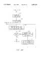
- FIGS. 9A, 9B and 9Cillustrate a flow chart representing the software that is executed by the microcontroller 104 of the communication device 100.
- the microcontroller 104begins executing at a block 600, as shown in FIG. 9A.
- the microcontroller 104accesses the ROM 134 and loads small portions of the software into random access memory (RAM) inside the microcontroller 104.
- RAMrandom access memory
- the software routines that are loaded into internal RAMare the routines that are generally executed most frequently.
- the microcontroller 104executes routines that are not loaded into RAM by directly accessing the ROM 134.
- the microcontroller 104sends messages over each of the above-described serial interfaces between the microcontroller 104 and the communication circuits 114, 120, 124, 126.
- the microcontroller 104waits for a response from each of the communication circuits 114, 120, 124, 126. This exchange of messages allows the microcontroller 104 to determine which of the communication circuits 114, 120, 124, 126 have been installed inside the communication device 100.
- the microcontroller 104sends a message to the PDA 102 over the primary serial port 106.
- the response from the PDA 102indicates whether software must be uploaded to the PDA 102.
- the microcontroller 104proceeds to a process block 608.
- the microcontroller 104reads code from the ROM 134 and transfers it to the PDA 102 over the primary serial port 106, if the previous response from the PDA 102 indicated that an upload was necessary.
- the required softwarecan be uploaded to the PDA 102 by an appropriate method, as required by the PDA 102.
- the AppleTM NewtonTMhas a well-defined method for uploading software from its serial port.
- the software that is uploaded to the PDA 102provides the user of the PDA 102 with access to the functions provided by the communication device 100.
- the software uploaded into the PDA 102provides an interface with the hardware and the software of the communication device 100.
- the microcontroller 104sends messages to any attached external devices through the pass-thru serial port 110.
- Each of the attached external devicesif any, responds to the microcontroller 104 through the pass-thru serial port 110. These responses allow the microcontroller 104 to determine the types of external devices that are attached to the pass-thru serial port 110.
- the microcontroller 104proceeds to a process block 612.
- the ROM 134may contain code that can be downloaded to external devices through the pass-thru serial port 110. If the ROM 134 contains code for one or more of the attached external devices, and one or more of those attached external devices require a software download, the microcontroller 104 reads the appropriate code from the ROM 134 and transfers it to the appropriate external devices through the pass-thru serial port 110.
- the microcontroller 104initializes each of the installed communication circuits 114, 120, 124,126, as required. For example, the microcontroller 104 may initiate a warm start in the GPS engine 120 by sending an appropriate command over the serial interface connecting the microcontroller 104 with the GPS engine 120. This warm start allows the GPS engine 120 to respond more quickly to a request from the PDA 102 for location data. As another example, the microcontroller 104 may send appropriate commands to program the cellular telephone 126, if the cellular telephone 126 has not yet been programmed.
- the microcontroller 104powers up the phone modem 114 by activating the signal on the modem enable line 334, as shown in FIG. 6.
- the microcontroller 104causes the decoder/multiplexer 112 to select the phone modem 114 for on-line operation by applying appropriate signals to the select lines 140 and 142, as shown in FIG. 4.
- the microcontroller 104enters a monitor mode.
- the microcontroller 104emulates a modem and relays data between the PDA 102 and the communication circuit 114, 120, 124, 126 that is currently on-line, while monitoring the communication stream generated by the PDA 102 for escape codes.
- the microcontroller 104continues to relay data between the PDA 102 and the on-line communication circuit 114, 120, 124, 126, until it receives either an escape code from the PDA 102 or an interrupt from one of the communication circuits 114, 120, 124 or 126 that is not selected for on-line operation.
- the phone modem 114can interrupt the microcontroller 104 by applying an active signal to the ring indicator line 332, as shown in FIG. 6.
- Either the packet radio 124 or the cellular telephone 126can interrupt the microcontroller 104 by activating the signal on the ring indicator line 510.
- the microcontroller 104Upon receiving either an escape code from the PDA 102 or an interrupt from an off-line communication circuit 114, 120, 124 or 126, the microcontroller 104 advances to a decision block 622.
- the microcontroller 104determines whether it received an escape code or an interrupt. If the microcontroller 104 received an escape code, then the microcontroller 104 advances to a process block 624. Otherwise, the microcontroller 104 advances to a decision block 628, as shown on FIG. 9C.
- the microcontroller 104reports any prior interrupts that have not yet been reported to the PDA 102. Specifically, the microcontroller 104 sends a message to the PDA 102 indicating which communication circuits 114,120,124 or 126 have interrupted the microcontroller 104. After reporting the prior interrupts, the microcontroller 104 advances to a process block 626.
- the microcontroller 104enters a command mode.
- the PDA 102can send a series of commands to the microcontroller 104 for controlling the communication circuits 114, 120, 124 and 126.
- Examples of possible commands that can be sent to the microcontroller 104include commands to power off the communication device 100, to wake up the PDA 102 upon receipt of an incoming cellular call, to select a communication circuit 114, 120, 124, 126 for on-line operation, to idle at low power and to check different status conditions.
- the microcontroller 104continues to execute commands received from the PDA 102 until the microcontroller 104 has selected a communication circuit 114, 120, 124 or 126 for on-line operation in response to a command from the PDA 102. At this point, the microcontroller 104 returns to the process block 620.
- the microcontroller 104checks the service response code for the communication circuit 114, 120, 124 or 126 that generated the interrupt.
- the service response codeindicates whether there are any actions that the microcontroller 104 should automatically perform in response to the interrupt. If the service response code indicates that the interrupt does not require service, then the microcontroller 104 advances to a decision block 636. If the service response code indicates that the interrupt does require servicing, then the microcontroller 104 advances to a process block 630.
- the microcontroller 104disables the serial interface between the PDA 102 and the communication circuit 114,120, 124 or 126 that is currently selected for on-line operation.
- the microcontroller 104disables this interface using the handshake lines 204, 208, 302 and 306, as is well known in the art.
- the microcontroller 104performs the appropriate steps to service the current interrupt from the communication circuit 114,120, 124 or 126. The steps performed during the process block 632 depend on the particular communication circuit 114, 120, 124 or 126 generating the interrupt and on the instructions that have been previously received from the PDA 102 related to the particular communication circuit 114, 120, 124 or 126.
- the cellular telephone 126generates an interrupt to the microcontroller 104 on the ring indicator line 510 upon receiving an incoming call. If the PDA 102 has previously set the cellular telephone 126 to an automatic answering mode inside the microcontroller 104, the microcontroller 104 causes the cellular telephone 126 to answer the incoming call during the process block 632. Specifically, the microcontroller 104 temporarily disables the interface between the PDA 102 and the communication circuit 114, 120 or 124 that has been selected for on-line operation and causes the decoder/multiplexer 112 to select the cellular telephone 126. The microcontroller 104 then generates appropriate commands to cause the cellular telephone 126 to answer the incoming call.
- the user of the PDA 102can then begin a telephone conversation with the remote caller using an external microphone and earphone connected to the microphone and earphone jack 132.
- the microcontroller 104controls the decoder/multiplexer 112 to again select the communication circuit 114,120 or 124 that had previously been selected for on-line operation.
- the microcontroller 104again enables the interface between the PDA 102 and the communication circuit 114,120, 124 or 126 by controlling the handshake lines 204,208, 302 and 306.
- the microcontroller 104advances to the decision block 636.
- the microcontroller 104checks the interrupt response code corresponding to the communication circuit 114,120,124 or 126 that generated the interrupt.
- the interrupt response codehas been previously set by the PDA 102 by a command to the microcontroller 104.
- the interrupt response codeindicates whether the microcontroller 104 should immediately interrupt the PDA 102, whether it should cause a delayed interrupt of the PDA 102, or whether it should not interrupt the PDA 102 at all. If the interrupt response code indicates that the microcontroller 104 should not interrupt the PDA 102, the microcontroller 104 returns to the process block 620. If the interrupt response code indicates that the microcontroller 104 should immediately interrupt the PDA 102, then the microcontroller 104 advances to a process block 640.
- the microcontroller 104advances to a process block 638.
- the microcontroller 104monitors the communication stream between the PDA 102 and the communication circuit 114, 120,124 or 126 that has been selected for on-line operation.
- the microcontroller 104detects a break in the communication stream, the microcontroller 104 advances to the process block 640.
- the microcontroller 104activates the GPI line 206, illustrated in FIG. 5, to cause an interrupt to the PDA 102.
- the response of the PDA 102 to the interrupt on the GPI line 206depends on the application program running on the PDA 102, if any.
- the microcontroller 104returns to the process block 620 of FIG. 9B.
- the PDA 102executes software that allows the PDA 102 to interface with and control the communication device 100.
- This softwaresends commands to the microcontroller 104 when the microcontroller 104 is in the command mode, and it sends data to the on-line communication circuit 114, 120, 124, 126 when the microcontroller 104 is in the monitor mode.
- the format and the content of the data sent to the different communication circuits 114,120,124,126complies with the requirements of the particular communication circuits 114, 120, 124, 126.
- the data sent to the phone modem 114complies with the standard Hayes® format for modems.
- the communication software for the PDA 102is uploaded to the PDA 102 from the ROM 134, and the software extends the capabilities of the PDA 102.
- the softwareis described in terms of using an AppleTM Newton® as the PDA 102.
- the system preferencesare extended to provide user access to the functions of the communication device. For example, the standard functions of Print, Fax, Mail and Call are modified to operate the communication circuits 114, 120, 124, 126 of the communication device 100.
- the Call functionplaces a cellular telephone call if the cellular telephone 126 is currently on-line.
- the Fax functionsends a facsimile over the phone modem 114 if the phone modem is currently on-line.
- the system preferencesare also extended to display information about the communication device 100. For example, if a packet of data is received at the packet radio 124, the In Box of the PDA 102 reflects the reception of this message.
- one or more application programsare also provided that allow more complete control of the functions of the communication device 100.
- one application programcan be used to control different functions of the cellular telephone 126, such as programming the cellular telephone 126 or placing a phone call.
- the Intelligent AssistantTM of the Newtonis also extended to understand commands for the communication device 100.
- a usercan write the phrase "Where am I?" on the LCD display 78 using the light pen 76.
- the extended Intelligent AssistantTMunderstands this as a command to activate the GPS engine 120 to determine the current location of the communication device 100.
- the PDA 102generates the appropriate commands to the communication device 100 to obtain the requested data from the GPS engine 120.
- the Intelligent AssistantTMpreferably utilizes the above-described application programs to control many functions of the communication device 100.
- the software uploaded to the PDA 102also includes proto end points, as defined by AppleTM specifications, that facilitate interfacing with the communication device 100 and controlling the operation of the communication device 100. These proto end points can be used by other application programs to access the communication device 100.
- the portable multiple integrated communication device 100 of the present inventionprovides versatile utilization of the communication circuits 114, 120, 124, 126.
- Datais channeled from a communication circuit 114, 120, 124 or 126, through the microcontroller 104, to the PDA 102.
- the datacan then be rerouted to any of the other communication circuits 114, 120, 124, 126.
- This data flow versatilityallows the different functions of the communication device 100 to be utilized in various combinations to provide numerous more complex functions.
- the GPS engine 120can be used in conjunction with the packet radio 124 to form an automated tracking system.
- the GPS engine 120can periodically generate location data to the PDA 102.
- This informationcan automatically be transmitted to an office computer using the packet radio 124, providing personnel at the office with continuous access to data indicating the location of the communication device 100, and consequently, the person using it.
- datacan be transferred directly between the cellular telephone 126 and the phone modem 114, further expanding the possibilities.
- digital datacan be transmitted over the cellular interface by routing the data from the PDA 102, through the microcontroller 104 and the phone modem 114, to the cellular telephone 126.
- the phone modem 114converts the digital data into a format that is compatible with cellular technology.
- the communication device 100 of the present inventioncan also be implemented with other optional devices or features.
- an optional lamp 135, as illustrated in FIG. 4can be controlled by the microcontroller 104 to illuminate the LCD display 78.
- other unitscan be used to replace the communication circuits 114, 120, 124, 126 of the present embodiment. These other units need not be communication circuits, either.
- FIGS. 10 to 15Cillustrate a second embodiment 100B of the portable multiple integrated communication device of the present invention.
- Many of the implementation details that have been described above with respect to the first embodiment 100also apply to the second embodiment 100B.
- the present description of the second embodiment 100Bfocuses on differences between the two embodiments.
- a person of skill in the artcan apply the more specific teachings described above with respect to the first embodiment 100 to the more general teachings described below with respect to the second embodiment 100B to fully implement the second embodiment 100B.
- the communication device 100Bhas a power supply that is similar to the power supply 146 of the communication device 100, although FIGS. 10-15C do not illustrate a power supply.
- FIG. 10illustrates a functional block diagram of the second embodiment communication device 100B connected to a PDA 102B.
- the PDA 102Bis the same as the PDA 102, except that the program executed in the PDA 102B to interface with the communication device 100B is different in some respects from the program executed in the PDA 102 to interface with the communication device 100.
- the PDA 102Bcomprises one or more application programs and an application server 710.
- FIG. 10illustrates a first application program 702, a second application program 704 and a third application program 706. Each of the application programs 702, 704, 706 is coupled to the application server 710.
- the communication device 100Bcomprises a communication server 750, the GPS engine 120, the cellular telephone 126, the phone modem 114, a land phone 708, the packet radio 124, and the pass-thru or external serial port 110.
- the application server 710 of the PDA 102Bis coupled to the communication server 750 of the communication device 100B by a serial interface 701.
- the serial interface 701 between the application server 710 and the communication server 750corresponds to the serial interface between the PDA 102 and the primary serial port 106 of the first embodiment communication device 100, as illustrated in FIG. 4.
- the communication server 750is coupled to the GPS engine 120 by a serial interface 703.
- the communication server 750is coupled to the cellular telephone 126 by a serial interface 705.
- the communication server 750is coupled to the phone modem 114 by a serial interface 707.
- the communication server 750is coupled to the packet radio 124 by a serial interface 709.
- the communication server 750is coupled to the external serial port 110 by a serial interface 711.
- the phone modem 114is also coupled to the land phone 708 and to the cellular telephone 126.
- the communication circuits 114, 120, 124, 126, as well as the external serial port 110are utilized for the same purposes as in the first embodiment communication device 100.
- Each application program 702, 704, 706can generally utilize any of the functions of the communication circuits 114, 120, 124, 126.
- the first application 702may utilize the GPS engine 120 and the packet radio 124
- the second application 704utilizes the phone modem 114.
- the cellular telephone 126 and the packet radio 124can be installed simultaneously.
- the second embodiment communication device 100Bincludes both a cellular telephone antenna 121 and a packet radio antenna 122 (See FIG. 4). In fact, all of the communication circuits 114, 120, 124, 126 can be installed simultaneously.
- the applications 702, 704, 706cause one or more data packets to be generated and communicated to the communication circuits 114,120,124, 126.
- the data packetscan contain commands to control the operation of the communication circuits 114, 120, 124, 126, or the data packets can contain requests for data, or the data packets can contain data for transmission by an appropriate communication circuit 114,120,124,126, such as the phone modem 114, the packet radio 124, or a device connected to the external serial port 110.
- Each data packetalso contains an address identifying the destination of the data packet.
- the destinationcan be any of the communication circuits 114,120, 124,126, or the external serial port 110.
- the application server 710generates data packets in response to function calls by the applications 702, 704, 706.
- the application server 710then transmits the data packets to the communication server 750.
- the communication server 750modifies the data packets before distributing the data packets to the appropriate communication circuits 114, 120, 124, 126, or to the external serial port 110.
- the application 704may cause the application server 710 to generate a data packet that requests positional data from the GPS engine 120.
- the application server 710transmits the data packet to the communication server 750.
- the communication server 750modifies the data packet before forwarding the data packet to the GPS engine 120.
- the communication circuits 114, 120, 124, 126 and devices connected to the external serial port 110also generate data packets for transmission to one or more of the applications 702, 704, 706. Each of the data packets identifies the type of data contained therein.
- the packet radio 124may generate a data packet containing data that has been received from a remote source.
- the communication circuits 114, 120, 124, 126 and the external serial port 110transmit the data packets to the communication server 750.
- the communication server 750modifies the data packets and transmits them to the application server 710, which also modifies the data packets.
- the application server 710also determines which applications 702,704, 706 have requested data of the type contained in a data packet, and sends the data packet to the appropriate applications 702, 704, 706.
- the PDA 102B and the communication device 100Bsuppose that a user of the PDA 102B wants to send data to a remote location using the phone modem 114 and the land phone 708.
- the usercan control one of the application programs 702, 704, 706, such as the first application 702 to control the phone modem 114.
- the first application 702first generates one or more data packets to initialize the phone modem 114 and to dial the desired phone number through the land phone 708.
- the first application 702sends one or more additional data packets containing the data to be transmitted.
- the application server 710transmits each of the data packets to the communication server 750, which modifies the data packets and routes them to the phone modem 114.
- the phone modem 114responds to the data packets to establish the requested communication with the remote location using the land phone 708.
- the phone modem 114then transmits the supplied data.
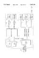
- FIG. 11is a functional block diagram of the application server 710 of FIG. 10.
- the application server 710comprises a set of service routines 712, a set of interface units 714, and an arbitrator 716.
- the set of service routines 712comprises a telephone server 730, a fax server 732, an e-mail server 734, a course deviation indicator server 736, and a packet data server 738.
- the set of interface units 714comprises a GPS interface 718, a cellular telephone interface 720, a phone modem interface 722, a land phone interface 724, a packet radio interface 726, and an external serial interface 728.
- the arbitrator 716comprises an application packet interface 740, an application packet distributor 742, a registry table 744, and a registration unit 746.
- Each of the applications 702, 704, 706is coupled to each of the service routines 730, 732, 734, 736, 738 and to each of the interface units 718, 720, 722, 724, 726, 728.
- the telephone server 730is coupled to the cellular telephone interface 720 and the land phone interface 724.
- the fax server 732is coupled to the cellular telephone interface 720, the phone modem interface 722, and the land phone interface 724.
- the e-mail server 734is coupled to the phone modem interface 722.
- the course deviation indicator server 736is coupled to the GPS interface 718.
- the packet data server 738is coupled to the packet radio interface 726.
- Each of the interface units 718, 720, 722, 724, 726, 728is coupled to the application packet interface 740, the application packet distributor 742, and the registration unit 746.
- the registration unit 746is coupled to the registry table 744, which is coupled to the application packet distributor 742.
- the application packet distributor 742is coupled to the application packet interface 740, which is coupled to the communication server 750 by the serial interface 701.
- the application packet distributor 742is also coupled to each of the applications 702, 704, 706.
- FIG. 12illustrates a software functional block diagram of the communication server 750 of FIG. 10.
- the communication server 750comprises a communication packet interface 752, a communication packet distributor 754, a generic GPS emulator 756, a generic cellular emulator 758, a generic modem emulator 760, and a generic packet radio emulator 762.
- the communication packet interface 752is coupled to the application server 710, and, more specifically, to the application packet interface 740 by the serial interface 701.
- the communication packet interface 752is also coupled to the communication packet distributor 754.
- the communication packet interface 752is coupled to the generic GPS emulator 756, the generic cellular emulator 758, the generic modem emulator 760, and the generic packet radio emulator 762.
- the communication packet distributor 754is also coupled to the generic GPS emulator 756, the generic cellular emulator 758, the generic modem emulator 760, and the generic packet radio emulator 762.
- the communication packet interface 752 and the communication packet distributor 754are also coupled to the external serial port 110 by the serial interface 711.
- the generic GPS emulator 756is coupled to the GPS engine 120 by the serial interface 703.
- the generic cellular emulator 758is coupled to the cellular telephone 126 by the serial interface 705.
- the generic modem emulator 760is coupled to the phone modem 114 by the serial interface 707.
- the generic packet radio emulator 762is coupled to the packet radio 124 by the serial interface 709.
- Each generic emulator 756, 758, 760, 762provides a common software interface to the application server 710 regardless of the specific model of communication circuit 114, 120, 124, 126 that implements a given communication function.
- the generic GPS emulator 756provides the same software interface to the application server 710 whether the GPS engine 120 is a Rockwell NavCore® VI MicroTrackerTM GPS circuit card, or some other GPS circuit card, made by Rockwell or another manufacturer.
- the application server 710can send the same format data packets to the generic GPS emulator 756 no matter which model of GPS engine 120 is utilized.
- the generic GPS emulator 756determines the model of GPS engine 120 that is attached to the communication device 100B and reformats received data packets to conform to the format required by the attached model.
- the generic cellular emulator 758, the generic modem emulator 760, and the generic packet radio emulator 762reformat received data packets to conform to the requirements of the specific models of communication circuits 126, 114, 124 that are attached.
- the communication packet interface 752receives data packets from the application packet interface 740 over the serial interface 701 and transfers the data packets to the communication packet distributor 754.
- the communication packet distributor 754reads the destination address of the data packets and transfers each of the data packets to the appropriate generic emulator 756, 758, 760, 762, or to the external serial port 110. For example, if the destination address of a data packet identifies the packet radio 124, the communication packet distributor 754 transfers the data packet to the generic packet radio emulator 762. If the destination address identifies a device connected to the external serial port 110, the communication packet distributor 754 transfers the data packet to the external serial port 110.
- the generic emulators 756, 758, 760, 762reformat any received data packets before transferring them to the addressed communication circuits 114, 120, 124, 126.
- the generic emulators 756, 758, 760, 762also receive data packets from the corresponding communication circuits 114, 120, 124, 126.
- the data packets received from the communication circuits 114,120, 124,126are in formats that are specific to the particular models of communication circuits 114, 120, 124, 126 that are attached to the communication device 100B.
- Each of the generic emulators 756, 758, 760, 762reformats the received data packets into a generic format.
- the Rockwell NavCore® VI MicroTrackerTM GPS circuit cardgenerates data packets that have a format that may be unique to that particular model of GPS engine 120.
- the generic GPS emulator 756reformats data packets received from the Rockwell NavCore® VI MicroTrackerTM GPS circuit card into the same pre-defined generic format that is used for other models of the GPS engine 120.
- the formats of the data packets generated by the generic emulators 756, 758, 760, 762are independent of the particular models of communication circuits 114, 120, 124, 126 that are attached to the communication device 100B.
- the communication packet interface 752receives data packets from each of the generic emulators 756,758, 760,762 and from the external serial port 110 and transmits the data packets to the application packet interface 740 over the serial interface 701.
- the interface units 718, 720, 722, 724, 726, 728generate data packets in response to user control of the applications 702, 704, 706 directly, or through the set of service routines 730, 732, 734, 736, 738.
- the data packets generated by the interface units 718, 720, 722,724,726,728conform to the requirements of corresponding generic emulators 756, 758, 760, 762 or to the requirements of devices connected to the external serial port 110.
- the GPS interface 718generates data packets according to the requirements of the generic GPS emulator 756, the cellular telephone interface 720 generates data packets according to the requirements of the generic cellular emulator 758, the phone modem interface 722 and the land phone interface 724 generate data packets according to the requirements of the generic modem emulator 760, the packet radio interface 726 generates data packets according to the requirements of the generic packet radio emulator 762, and the external serial interface 728 generates data packets according to the requirements of the devices that are connected to the external serial port 110.
- the data packets that are generated by the interface units 718,720, 722, 724, 726, 728are sent to the application packet interface 740, which transmits the data packets to the communication packet interface 752, over the serial interface 701.
- the applications 702, 704, 706can interact directly with the interface units 718, 720, 722, 724, 726, 728 to cause the interface units 718, 720, 722, 724, 726, 728 to generate the desired data packets.
- the application 704can call a routine or method within the cellular telephone interface 720 that causes the cellular telephone interface 720 to generate a data packet to cause the cellular telephone 126 to dial a specified telephone number.
- the applications 702, 704, 706can utilize the service routines 730, 732, 734, 736, 738 to assist in the control of the communication circuits 114, 120, 124, 126.
- the service routines 730, 732, 734, 736, 738implement many of the same functions that are provided directly from the interface units 718, 720, 722, 724, 726, 728. However, the functions of the service routines 730, 732, 734, 736, 738 are arranged in a functional manner for the convenience of the user. For example, a user can select a function to dial a phone number from the telephone server 730, and the telephone server 730 either causes the cellular telephone interface 720 to generate a data packet for the cellular telephone 126, or it causes the land phone interface 724 to generate a data packet for the land telephone 708, depending on which type of telephone has been previously selected for operation.
- the application packet interface 740receives generic data packets from the communication packet interface 752.
- the application packet interface 740provides the received data packets to the application packet distributor 742.
- the application packet distributor 742requests that the appropriate interface units 718, 720, 722, 724, 726, 728 process the generic data packets to extract data required by the applications 702, 704, 706.
- the application packet distributor 742refers to the registry table 744 to determine which applications should receive the data packets after the data packets have been processed by the appropriate interface units 718, 720, 722, 724, 726, 728.
- the application packet distributor 742sends the processed data packets directly to the appropriate applications 702, 704, 706.
- the telephone server 730can be used to process incoming and outgoing phone calls using either the cellular telephone interface 720 or the land phone interface 724, depending on which type of telephone interface has been previously selected.
- the telephone server 730provides various functions to the applications 702,704,706, such as allowing for the selection of a type of telephone interface for subsequent operations, dialing a telephone number, answering a call, terminating a phone connection, determining the current signal strength, redialing the last dialed number, setting the volume level for an attached earphone, setting a volume level for the ringer of the selected telephone 126, 708, sending tones from the selected telephone 126, 708, determining the air time that has been consumed, determining the battery level of the communication device 100B, determining the current roam state, and determining the current service state.
- the fax server 732can be used to send and receive data using the phone modem interface 722 and either the cellular telephone interface 720 or the land phone interface 724.
- the fax server 732also provides functions such as allowing for the selection of a type of telephone interface for subsequent operations, powering on or off the phone modem 114, dialing a telephone number, answering a call, sending or receiving a fax, controlling the phone modem 114 to automatically receive a fax, and terminating a phone connection.
- the e-mail server 734can be used to send and receive data using the phone modem interface 722.
- the e-mail server 734also provides functions such as powering on or off the phone modem 114, sending or receiving an e-mail, and controlling the phone modem 114 to automatically receive an e-mail.
- the course deviation indicator server 736can be used to determine a user's current location or to obtain directions to a desired location using the GPS interface 718.
- the course deviation indicator server 736also provides functions such as determining whether a GPS engine 120 is present, powering on or off the GPS engine 120, determining or setting the current operating state of the GPS engine 120, and requesting periodic position data from the GPS engine 120.
- the packet data server 738can be used to send and receive data using the packet radio interface 726.
- the packet data server 738also provides functions such as determining whether a packet radio 124 is attached to the communication device 100B, powering on or off the packet radio 124, causing the packet radio 124 to execute a cold start, determining and setting the operating mode of the packet radio 124, determining the number of packets waiting to be read or transmitted, determining the signal strength, determining status results regarding the data packet link or regarding a specific transmission or reception, setting a channel for transmission or reception, and setting the packet radio 124 to automatically receive data packets.
- the GPS interface 718can be used to control the GPS engine 120 to determine the location of the PDA 102B and the communication device 100B to within 25 meters.
- the GPS interface 718provides a number of functions, such as determining whether a GPS engine 120 is present, powering on or off the GPS engine 120, determining the current battery level of the communication device 100B, determining or setting the power management mode of the GPS engine 120, determining or setting the current operating state of the GPS engine 120, requesting periodic position data from the GPS engine 120, requesting satellite information from the GPS engine 120, and initiating a self test in the GPS engine 120.
- the cellular telephone interface 720can be used for incoming and outgoing cellular phone calls.
- the cellular telephone interface 720can also be used in conjunction with the phone modem interface 722 to send and receive data over a cellular link.
- the cellular telephone interface 720provides functions such as determining whether a cellular telephone 126 is attached to the communication device 100B, dialing a telephone number, answering a call, terminating a phone connection, determining the current signal strength, redialing the last dialed number, setting the volume level for an attached earphone, setting a volume level for the ringer of the cellular telephone 126, sending tones from the cellular telephone 126, determining the air time that has been consumed, determining the battery level of the communication device 100B, determining the current roam state, determining the current service state.
- the phone modem interface 722is used in conjunction with either the cellular telephone interface 720 or the land phone interface 724 to send and receive data.
- the phone modem interface 722also provides functions such as allowing for the selection of a type of telephone interface for subsequent operations, determining the battery level of the communication device 100B, powering on or off the phone modem 114, sending data or receiving data, sending a fax or receiving a fax, controlling the phone modem 114 to automatically receive data or a fax, providing a special escape sequence to cause the phone modem 114 to exit an on-line mode and return to a command mode, and generating AT commands to the phone modem 114.
- the land phone interface 724is primarily used in conjunction with the phone modem interface 722 to send and receive data, and for voice calls.
- the land phone interface 724also provides functions such as determining whether a land phone 708 is attached to the communication device 100B, dialing a telephone number, answering a call, terminating a phone connection, determining the current signal strength, redialing the last dialed number, setting the volume level for an attached earphone, setting a volume level for the ringer of the land phone 708, sending tones from the land phone 708, determining the air time that has been consumed, and determining the battery level of the communication device 100B.
- the packet radio interface 726provides access to the packet radio 124, and implements functions such as determining whether a packet radio 124 is attached to the communication device 100B, powering on or off the packet radio 124, causing the packet radio 124 to execute a cold start, determining the battery level of the communication device 100B, determining and setting the power management mode of the packet radio 124, determining and setting the operating mode of the packet radio 124, determining the number of packets waiting to be read or transmitted, determining the signal strength, determining status results regarding the data packet link or regarding a specific transmission or reception, setting a channel for transmission or reception, and setting the packet radio 124 to automatically receive data packets.
- the external serial interface 728provides access to devices connected to the external serial port 110, and implements functions such as determining the battery level of the communication device 100B and determining the state of the external serial port 110.
- Each of the interface units 718,720, 722,724,726,728can also set the corresponding communication circuit 114, 120, 124, 126 or the external serial port 110 into a native mode that allows the communication circuits 114, 120, 124, 126 and the external serial port 110 to receive and execute commands that are similar to those that are described above with reference to the first embodiment communication device 100.
- FIG. 13illustrates a hardware functional block diagram of the communication server 750 of FIG. 10, along with the GPS engine 120, the cellular telephone 126, the phone modem 114, the packet radio 124, and the external serial port 110.
- the communication server 750comprises a RAM 770, a microcontroller 772, a ROM 774, and a quad universal asynchronous receiver transmitter (quad UART) 776.
- the quad UART 776is coupled to the application packet interface 740 by the serial interface 701.
- the quad UART 776is connected to both the microcontroller 772 and the RAM 770 by a parallel interface 771.
- the quad UART 776is connected to the phone modem 114 by the serial interface 707.
- the quad UART 776is connected to the packet radio 124 by the serial interface 709.
- the quad UART 776is connected to the external serial port 110 by the serial interface 711.
- the microcontroller 772is connected to the ROM 774.
- the microcontroller 772is connected to the GPS engine 120 by the serial interface 703.
- the microcontroller 772is connected to the cellular telephone 126 by the serial interface 705.
- the microcontroller 772preferably comprises an Intel® 80C320 microcontroller.
- the quad UART 776preferably comprises a Startech ST16C454 quad UART.
- the RAM 770preferably comprises a Fujitsu MB84256A 32Kx8 static RAM, or a similar device.
- the ROM 774preferably comprises a Texas Instruments 29F010 128Kx8 flash memory, or a similar device.
- the communication packet interface 752, the communication packet distributor 754, and the generic emulators 756, 758, 760, 762are implemented in software inside the ROM 774 that is executed by the microcontroller 772.
- the quad UART 776effectively provides the microcontroller 772 with four additional serial ports.
- the microcontroller 772receives data packets directly from the GPS engine 120 and the cellular telephone 126 via the serial interfaces 703, 705. Generally, the slower communication circuits 114, 120, 124, 126 are connected directly to the microcontroller 772.
- the transmitting communication circuit 120, 126generates a vectored interrupt to the microcontroller 772.
- the microcontroller 772receives the incoming data packet and stores the data in the RAM 770.
- the microcontroller 772processes the stored data packet and transfers the data packet to the quad UART 776 over the parallel interface 771 for transmission to the application packet interface 740 over the serial interface 701.
- the quad UART 776receives data packets from the application packet interface 740 over the serial interface 701, from the phone modem 114 over the serial interface 707, from the packet radio 124 over the serial interface 709, and from the external serial port 110 over the serial interface 711.
- the quad UART 776receives a single interrupt signal in connection with the receipt of any of the received data packets.
- the quad UART 776polls the serial ports to determine which port has received a data packet.
- the quad UART 776receives the data packet and transfers the data packet to the microcontroller 772.
- the quad UART 776interrupts the microcontroller 772 with a vectored interrupt indicative of the serial port that received the data packet.
- the quad UART 776interrupts the microcontroller 772 using a vector that indicates to the microcontroller 772 that the data packet was received from the packet radio 124.
- the microcontroller 772processes data packets received from the phone modem 114, the packet radio 124 and the external serial port 110 before returning the data packets to the quad UART 776 for transmission to the application packet interface 740 over the serial interface 701.
- the microcontroller 772also processes data packets that have been received by the quad UART 776 over the serial interface 701. After processing such a data packet, if the data packet is addressed to the GPS engine 120, the microcontroller 772 transmits the data packet directly to the GPS engine 120 over the serial interface 703. If the data packet is addressed to the cellular telephone 126, the microcontroller 772 transmits the data packet directly to the cellular telephone 126 over the serial interface 705. If the data packet is addressed to the phone modem 114, the microcontroller 772 transfers the data packet to the quad UART 776 over the parallel interface 771, which subsequently transmits the data packet to the phone modem 114 over the serial interface 707.
- the microcontroller 772transfers the data packet to the quad UART 776 over the parallel interface 771, which subsequently transmits the data packet to the packet radio 124 over the serial interface 709. If the data packet is addressed to the external serial port 110, the microcontroller 772 transfers the data packet to the quad UART 776 over the parallel interface 771, which subsequently transmits the data packet to the external serial port 110 over the serial interface 711. Data packets can also be addressed to the microcontroller 772 to control different aspects of the operation of the microcontroller 772.
- a data packetcan be sent to the microcontroller 772 to control the selection of an interconnection between the cellular telephone 126, the phone modem 114, the microphone and earphone jack 132, and the land phone 708, as described in greater detail below with reference to FIG. 14.
- FIG. 14illustrates a functional block diagram of the interface between the cellular telephone 126, the phone modem 114, the microphone and earphone jack 132, and the land phone 708.
- the land phone 708comprises the DAA 116 and the phone jack 118.
- FIG. 14also illustrates a quad 4-to-1 multiplexer/decoder 780, the microphone amplifier 128, and the earphone amplifier 130.
- the functionality of the quad 4-to-1 multiplexer/decoder 780is implemented with a 74HC4053 multiplexer and a number of 74HC4066 electronic switches.
- An output of the cellular telephone 126is connected to a first input and a second input of a first 4:1 multiplexer of the multiplexer/decoder 780.
- An output of the phone modem 114is connected to a third input of the first multiplexer of the multiplexer/decoder 780.
- An output of the microphone amplifier 128is connected to a fourth input of the first multiplexer of the multiplexer/decoder 780.
- An output of the first multiplexer of the multiplexer/decoder 780is connected to an input of a first 1:4 decoder of the multiplexer/decoder 780.
- a first output of the first decoder of the multiplexer/decoder 780is connected to an input of the earphone amplifier 130.
- a second output of the first decoder of the multiplexer/decoder 780is connected to an input of the phone modem 114.
- a third output and a fourth output of the first decoder of the multiplexer/decoder 780are connected to an input of the DAA 116.
- the output of the microphone amplifier 128is connected to a first input of a second 4:1 multiplexer of the multiplexer/decoder 780.
- the output of the phone modem 114is connected to a second input of the second multiplexer of the multiplexer/decoder 780.
- An output of the DAA 116is connected to a third input and a fourth input of the second multiplexer of the multiplexer/decoder 780.
- An output of the second multiplexer of the multiplexer/decoder 780is connected to an input of a second 1:4 decoder of the multiplexer/decoder 780.
- a first output and a second output of the second decoder of the multiplexer/decoder 780are connected to an input of the cellular telephone 126.
- a third output of the second decoder of the multiplexer/decoder 780is connected to the input of the phone modem 114.
- a fourth output of the second decoder of the multiplexer/decoder 780is connected to the input of the earphone amplifier 130.
- an output of the earphone amplifier 130is connected to an input of the microphone and earphone jack 132, an output of the microphone and earphone jack 132 is connected to an input of the microphone amplifier 128, an output of the DAA 116 is connected to an input of the phone jack 118, and an output of the phone jack 118 is connected to an input of the DAA 116.
- the microcontroller 772controls the operation of the multiplexer/decoder 780 by the use of two select lines.
- the same two select linesare connected to each of the multiplexers and each of the decoders of the multiplexer/decoder 780 in the same manner, so that corresponding inputs of the multiplexers and outputs of the decoders are always selected simultaneously. For example, if the second input of the first multiplexer is selected, the second input of the second multiplexer, the second output of the first decoder and the second output of the second decoder are also selected.
- the cellular telephone 126is coupled to the microphone and earphone jack 132. In this mode, a user can use an attached microphone and earphone to communicate to a remote party using a cellular system.
- the cellular telephone 126is coupled to the phone modem 114.
- datacan be sent from the PDA 102B to a remote destination or received at the PDA 102B from a remote source, through the phone modem 114, again using a cellular system.
- the microcontroller 772must first control the cellular telephone 126 directly to dial the desired number and establish the cellular link.
- the microcontroller 772can send data through the phone modem 114 to the cellular telephone 126 to be transmitted over the cellular link to a remote location, or data can be transmitted from a remote location to the cellular telephone 126, which sends the data through the phone modem 114 to the microcontroller 772. In this latter event, the phone modem 114 generates a data packet to be transmitted to the application packet interface 740.
- the phone modem 114is coupled to the land phone 708. In this mode, data can be sent from the PDA 102B to a remote destination or received at the PDA 102B from a remote source, through the phone modem 114, using a land-based telephone line.
- the microphone and earphone jack 132is coupled to the land phone 708. In this mode, a user can use an attached microphone and earphone to communicate to a remote party using a land-based telephone line.
- an alternative interconnectioncould be used that would allow multiple connections to be established simultaneously.
- an alternative embodimentcan allow data to be transferred over a cellular system using the phone modem 114 and the cellular telephone 126, while a user talks over a land-based telephone line using an attached microphone and earphone and the land phone 708.
- FIGS. 15A, 15B, and 15Cillustrate a method performed by the arbitrator 716 during operation of the PDA 102B and the communication device 100B. The method begins at an initial block 800 of FIG. 15A.
- the arbitrator 716initializes the application server 710 and the serial interface 701.
- the serial interface 701is initialized by transmitting an initialization data packet to the communication server 750.
- the communication server 750receives the initialization data packet and transmits a response data packet back to the arbitrator 716 to verify initialization of the serial interface 701. Either the arbitrator 716 or the communication server 750 can also initialize the serial interface 701 at other times, as required, by a similar process. If the communication server 750 initializes the serial interface 701, the communication server 750 transmits the initialization data packet, and the arbitrator 716 transmits the response data packet.
- the arbitrator 716awaits communication from other functional units.
- the arbitrator 716may receive a request for registration from an application 702, 704,706 through one of the interface units 718, 720, 722,724, 726, 728.
- a request for registrationis received by the registration unit 746.
- the arbitrator 716may receive an outgoing data packet (opack) from an application 702, 704, 706, again through one of the interface units 718, 720, 722, 724, 726, 728.
- An outgoing data packetis received by the application packet interface 740.
- the arbitrator 716may receive an incoming data packet (ipack) from the communication server 750 over the serial interface 701. An incoming data packet is also received by the application packet interface 740.
- the arbitrator 716determines which type of communication has been received. If a registration request has been received, the arbitrator 716 advances to a process block 808. If an outgoing data packet has been received, the arbitrator 716 advances to a process block 810. If an incoming data packet has been received, the arbitrator 716 advances to a process block 812.
- the arbitrator 716processes the registration request.
- the method for processing a registration requestis described in greater detail below with reference to FIG. 15B.
- the arbitrator 716advances to the process block 804 to await further communication.
- the arbitrator 716transmits the outgoing data packet to the communication server 750 over the serial interface 701. After the process block 810, the arbitrator 716 also advances to the process block 804.
- the arbitrator 716processes the incoming data packet.
- the method for processing an incoming data packetis described in greater detail below with reference to FIG. 15C.
- the arbitrator 716also advances to the process block 804.
- FIG. 15Billustrates the method performed by the registration unit 746 at the process block 808 of FIG. 15A to process a registration request.
- the method of FIG. 15Bbegins at an initial block 820.
- the registration unit 746determines which application 702, 704, 706 requested the registration. This information is provided by the requesting application 702, 704, 706 in the registration request.
- the registration unit 746determines the type of registration request that has been received.
- the registration requestcan specify a request to either establish or cancel a registration.
- the registration requestalso identifies a particular type of data packet.
- a requesting application 702, 704, 706may request to receive a data packet generated by the GPS engine 120 containing positional data related to the PDA 102B.
- the requesting application 702,704,706can also request either a one-shot registration or a continuous registration. A one-shot registration is canceled after a first data packet is received by the arbitrator 716 that matches the type of data packet requested by the requesting application 702,704,706. If the registration unit 746 registers a continuous registration request, the requesting application 702, 704, 706 continues to receive incoming data packets that match the requested type until the registration is canceled.
- the registration unit 746checks for a conflict between the current registration request and the registered requests in the registry table 744.
- a conflictmay occur, for example, if there is no registered request in the registry table 744 that matches a current request to cancel a registration.
- a conflictmay also occur if a request to establish a registration matches a previously registered request, or under other circumstances. If the registration unit 746 detects a conflict, the method advances to a process block 830. Otherwise, the method advances to a process block 832.
- the registration unit 746generates an error indication and advances to a terminal block 834.
- the registration unit 746modifies the registry table 744 according to the registration request. If the request seeks to cancel a registered request, the registration unit 746 deletes the entry in the registry table 744 that corresponds to the current request. If the request seeks to register a new request, the registration unit 746 generates a new entry in the registry table 744 identifying the type of registration requested. After the process block 832, the registration unit 746 advances to the terminal block 834, at which the method ends.
- FIG. 15Cillustrates the method performed by the application packet distributor 742 at the process block 812 of FIG. 15A to process an incoming data packet.
- the method of FIG. 15Cbegins at an initial block 840.
- Incoming data packetsare received by the application packet interface 740, which stores the received data packets in the memory of the PDA 102B.
- the application packet interface 740then notifies the application packet distributor 742 of the location of the data packets in memory.
- the application packet distributor 742determines the type of data packet that has been received.
- a data packetcan contain specific data that has been requested by an application 702, 704, 706, it can contain incoming data from one of the communication circuits 114, 120, 124, 126 or from the external serial port 110, or it can contain information reflecting changes in the communication device 100B.
- the application packet distributor 742determines which interface unit 718, 720, 722, 724, 726, 728 is related to the incoming data packet. For example, if the data packet contains positional data from the GPS engine 120, the related interface unit 718, 720,722, 724, 726, 728 is the GPS interface 718.
- the application packet distributor 742searches the registry table 744 to determine which applications 702,704,706 have registered requests for the type of data packet that has been received.
- the application packet distributor 742also deletes entries in the registry table 744 that identify one-shot requests that correspond to the type of data packet that has been received.
- the application packet distributor 742requests that the related interface unit 718, 720, 722,724, 726, 728 process the incoming data packet, as required, to extract the data that is desired by each of the applications 702, 704, 706 that have registered requests for the type of data that has been received.
- the methodadvances to a process block 850.
- the application packet distributor 742distributes the processed data packet to each of the applications 702, 704, 706 that has registered a request for the type of data that has been received.
- the application packet distributor 742advances to the terminal block 852, at which the method ends.
- the second embodiment communication device 100Bin conjunction with the PDA 102B, suppose that a user wants to send a document that is stored in the PDA 102B to a remote destination via facsimile, over a land-based telephone line. Assume that the user executes the application program 702 to facilitate sending the fax.
- the application 702allows the user to enter the phone number to which the fax should be sent, and it allows the operator to identify the file to be transmitted.
- the application 702may also allow the user to set other parameters of the facsimile transmission.
- the application 702calls one or more functions in the fax server 732 to establish the telephone link with the remote destination.
- the fax server 732may call one or more functions in the phone modem interface 722 and the land phone interface 724 to generate one or more data packets for transmission to the phone modem 114.
- the application 702may call a function in the fax server 732 to dial the user-specified phone number.
- the fax server 732calls a corresponding function in the land phone interface 724.
- the land phone interface 724generates a data packet that instructs the phone modem 114 to dial the user-specified phone number.
- the data packet generated by the land phone interface 724is directed to a generic phone modem 114, so that it may not be compatible with the phone modem 114 that is actually installed in the communication device 100B.
- the generic modem emulator 760modifies the generic modem data packet to conform to the requirements of the phone modem 114 that is actually installed in the communication device 100B.
- the generic modem emulator 760then transmits the modified data packet to the phone modem 114, which dials the user-specified phone number.
- the application 702calls one or more functions in the fax server 732 to send the file to the remote destination.
- the fax server 732calls one or more functions in the phone modem interface 722 and the land phone interface 724 to generate one or more data packets containing the data in the file.
- the generic modem emulator 760again modifies the data packets, and transmits them to the phone modem 114.
- the phone modem 114transmits the file to the remote destination.
- the application 702calls one or more functions in the fax server 732 to terminate the connection with the remote destination.
- the fax server 732calls one or more functions in the phone modem interface 722 and the land phone interface 724 to generate one or more data packets to terminate the connection.
- the generic modem emulator 760again modifies the data packets, and transmits them to the phone modem 114.
- the phone modem 114proceeds to terminate the connection with the remote destination, and the process of transmitting the selected file via facsimile is completed.
Landscapes
- Engineering & Computer Science (AREA)
- Theoretical Computer Science (AREA)
- Human Computer Interaction (AREA)
- Computer Hardware Design (AREA)
- General Engineering & Computer Science (AREA)
- Physics & Mathematics (AREA)
- General Physics & Mathematics (AREA)
- Computing Systems (AREA)
- Computer Networks & Wireless Communication (AREA)
- Signal Processing (AREA)
- Mobile Radio Communication Systems (AREA)
Abstract
Description
This is a Continuation-in-part of U.S. patent application Ser. No. 08/152,492, filed Nov. 15, 1993 now abandoned.
1. Field of the Invention
The present invention is in the field of portable communication devices for providing a computer with multiple integrated communication media, such as a phone modem, a cellular telephone, a packet radio and a Global Positioning System engine. In particular, the present invention relates to a portable multiple integrated communication device for a palm computer.
2. Background Information
Recent advances in the manufacture of integrated circuit components have allowed ever increasing functional capabilities to be performed by fewer integrated circuit components. This increased density of processing power in modern electronic equipment allows for the design of small, portable instruments with impressive processing capabilities. Advances in other technological areas, such as LCD displays, pen-based input devices and handwritten character recognition, have also contributed to a new generation of truly portable computers that are aptly described as palm computers or personal digital assistants (PDAs), but which have sufficient processing capabilities for numerous tasks. Examples of such PDAs include the Apple™ Newton™ and the Sharp™ Expert Pad™. These computers allow a user to take notes, store data, retrieve data, run certain application programs and interface with external devices, such as printers, modems or an Appletalk™ network.
The present invention connects to and interfaces with a PDA to dramatically increase the functional capabilities of the PDA. The present invention adds multiple integrated communication media to the resources currently available to the PDA, while maintaining a compact, portable size. For example, the combination of the present invention with a PDA can be used to place or receive a cellular telephone call or a land line telephone call, to transmit or receive packet radio data, to obtain three-dimensional location data from the Global Positioning System (GPS) and to send or receive data over a telephone cellular link or over a land line using a built in phone modem. These added communication features greatly enhance the utility of the PDAs. Instead of having a stand-alone PDA, isolated from other data sources, such as a person's office computer network, the combined PDA and multiple integrated communication device provides a powerful processing device with convenient access to vast stores of information over a variety of possible media.
One aspect of the present invention involves a portable communication device. The communication device comprises first and second communication circuits providing first and second differing modes of communication, a first generic emulator coupled to the first communication circuit and a second generic emulator coupled to the second communication circuit, a first interface unit coupled to the first generic emulator and a second interface unit coupled to the second generic emulator, and an application program. The application program accesses the first interface unit to generate a first command to control the operation of the first communication circuit. The application program accesses the second interface unit to generate a second command to control the operation of the second communication circuit. The first interface unit communicates the first command to the first generic emulator. The second interface unit communicates the second command to the second generic emulator. The first generic emulator reformats the first command and communicates the first command to the first communication circuit. The second generic emulator reformats the second command and communicates the second command to the second communication circuit. The first communication circuit executes the first command and the second communication circuit executes the second command.
Additional aspects of the present invention will be apparent in the following detailed description of the invention.
FIG. 1 is a perspective view of a palm computer for use with the portable multiple integrated communication device of the present invention.
FIG. 2 is a perspective view of the communication device of the present invention.
FIG. 3 is a perspective view of a palm computer mounted inside the communication device of the present invention.
FIG. 4 is a general functional block diagram of a first embodiment of the communication device of the present invention, connected to a palm computer.
FIG. 5 is a more detailed functional block diagram of the serial interface between the microcontroller and the pair of serial ports of FIG. 4.
FIG. 6 is a more detailed functional block diagram of the phone modem interface of FIG. 4.
FIG. 7 is a more detailed functional block diagram of the GPS engine interface of FIG. 4.
FIG. 8 is a more detailed functional block diagram of the packet radio interface and the cellular telephone interface of FIG. 4.
FIGS. 9A, 9B and 9C illustrate a flow chart of a computer program executed by the microcontroller of FIG. 4.
FIG. 10 is a functional block diagram of a second embodiment of the communication device of the present invention connected to a palm computer that has been programmed to implement an improved interface with the communication device.
FIG. 11 is a functional block diagram of the application server of FIG. 10.
FIG. 12 is a functional block diagram of the software of the communication server of FIG. 10.
FIG. 13 is a functional block diagram of the hardware of the communication server of FIG. 10.
FIG. 14 is a functional block diagram of the interconnections between the cellular telephone, the phone modem, the microphone and earphone jack and the phone jack of the second embodiment.
FIGS. 15A, 15B, and 15C illustrate a flow chart of the method implemented by the arbitrator of FIG. 11.
FIG. 1 illustrates a palm computer or personal digital assistant (PDA) 102 for use with the present invention. ThePDA 102 comprises anLCD display 78, alight pen 76, aDC power connector 50 and aserial interface connector 52. The PDA 102 provides an operator with a variety of data processing and data storage functions in a lightweight, portable device.
FIGS. 2 to 9C illustrate afirst embodiment 100 of the portable multiple integrated communication device of the present invention. FIG. 2 illustrates a perspective view of thecommunication device 100. Externally, thecommunication device 100 comprises afixed securing surface 56, a supportingsurface 57, amovable securing surface 58, a GPS antenna 123 (FIG. 7), either a cellular telephone antenna 121 (FIG. 8) or apacket radio antenna 122, a microphone andearphone jack 132, a serial/power interface connector 60, a serial/power interface cable 62, aphone jack 118, a pass-thruserial interface connector 68, aDC power connector 70 and a set of threeLEDs LEDs
FIG. 3 illustrates thePDA 102 of FIG. 1 inserted into thecommunication device 100 of FIG. 2. ThePDA 102 is inserted into thecommunication device 100 by pressing the bottom end of thePDA 102 against thesecuring surface 58 to rotate thesecuring surface 58 toward its open position (shown by the phantom lines in FIG. 2) until the top end of thePDA 102 clears thefixed securing surface 56, lowering thePDA 102 against the supportingsurface 57, with the orientation of FIG. 3. ThePDA 102 is then released, and a spring (not shown) rotates thesecuring surface 58 to its closed position, as shown by the solid lines in FIGS. 2 and 3, pressing the top end of thePDA 102 against thesecuring surface 56. Next, the remote serial/power interface connector 60 of thecommunication device 100 is inserted into both theDC power connector 50 and theserial interface connector 52 of thePDA 102. The combination of thePDA 102 and thecommunication device 100 forms a small, lightweight unit that is convenient to carry around and to use.
The structure of thecommunication device 100 is preferably designed to allow access to connectors and controls of thePDA 102. For example, thesecuring surface 56 of thecommunication device 100 preferably has an opening corresponding to a slot in the top end of the Sharp™ Expert Pad™, for insertion of an IC card into the slot of the Expert Pad™. Thepacket radio antenna 122 and the cellular telephone antenna 121 (shown in FIG. 8) of thecommunication device 100 are preferably mounted so that they can be rotated between an active position and an inactive position. In the active position, theantenna communication device 100, as shown in FIG. 3, to achieve optimal reception. In the inactive position, theantenna communication device 100 that is directly opposite the side with thephone jack 118. TheGPS antenna 123 may be mounted on the frame of thecommunication device 100, or it may be a separate device.
FIG. 4 illustrates a general functional block diagram of the first embodiment of the portable multipleintegrated communication device 100 of the present invention, connected to aPDA 102. Thecommunication device 100 comprises a primaryserial port 106, abuffer 108, a pass-thruserial port 110, aDC power connector 148, apower supply 146, apower connector 144, amicrocontroller 104, a read-only memory (ROM) 134, alamp 135, a decoder/multiplexer 112, aphone modem 114, a Data Access Arrangement (DAA) 116, thephone jack 118, a Global Positioning System (GPS)engine 120, theGPS antenna 123, either apacket radio 124 or acellular telephone 126, amicrophone amplifier 128, anearphone amplifier 130, the microphone andearphone jack 132, and either thepacket radio antenna 122 or thecellular telephone antenna 121. The decoder/multiplexer 112 comprises a dual 1:4 decoder ordemultiplexer 136 and a dual 4:1 multiplexer or selector 138. In the first embodiment of the present invention, thecommunication device 100 comprises either thepacket radio 124 or thecellular telephone 126, but not both. In one embodiment, the circuit card implementing thepacket radio 124 occupies the same physical space inside thecommunication device 100 as the circuit card implementing thecellular telephone 126, thus conserving space and reducing the size of thecommunication device 100.
Themicrocontroller 104 preferably comprises an Intel® 80C320 microcontroller, although numerous other processors could be used. Themicrocontroller 104 communicates with thePDA 102 through the primaryserial port 106. The serial/power interface cable 62 of FIGS. 2 and 3 is connected to the primaryserial port 106 and thepower connector 144 of FIG. 4. The primary serial port 160 is used for the communication of commands and data between themicrocontroller 104 and thePDA 102, as well as for the downloading of program code from theROM 134 to thePDA 102. Thepower connector 144 provides DC power from thepower supply 146 to thePDA 102. Thepower supply 146 also provides DC power to circuitry in thecommunication device 100. Thepower supply 146 preferably comprises batteries. However, DC power can also be provided by an external source through theDC power connector 148 to thepower supply 146. Themicrocontroller 104 can cause thepower supply 146 to power down, either as a result of a command from thePDA 102 or after a period of inactivity, to conserve battery power.
Thecommunication device 100 also has the separate pass-thruserial port 110 to allow other external devices to communicate with thePDA 102. Such devices may include printers, phone modems or an Appletalk™ network. The pass-thruserial port 110 is connected to the pass-thruserial interface connector 68 of FIGS. 2 and 3. Thebuffer 108 is used to enable or disable theserial port 110. In the first embodiment, thebuffer 108 comprises an LTC1032 component. If themicrocontroller 104 needs to transmit data to thePDA 102 or receive data from thePDA 102, themicrocontroller 102 disables thebuffer 108. Otherwise, thebuffer 108 is enabled to allow an external device to communicate with thePDA 102 through theserial port 110 and the primaryserial port 106. The serial interfaces between themicrocontroller 104, thePDA 102 and external devices are described in greater detail below with reference to FIG. 5.
TheROM 134 comprises a 27C1001 128Kx8 ultraviolet erasable EPROM from NEC, or the like, in the first embodiment. TheROM 134 contains code for both themicrocontroller 104 and thePDA 102. TheROM 134 may also contain code for standard external devices. Themicrocontroller 104 executes code in theROM 134 to implement the described functions of thecommunication device 100. Themicrocontroller 104 also uploads code from theROM 134 through the primaryserial port 106 into thePDA 102. ThePDA 102 executes this code to provide an interface with themicrocontroller 104 and to support and control the functions of thecommunication device 100. After the code in theROM 134 is loaded into thePDA 102, an operator of the combinedPDA 102 and thecommunication device 100 can utilize the functions provided by both thePDA 102 and thecommunication device 100 by providing appropriate input commands to thePDA 102. ThePDA 102 sends appropriate commands and data to themicrocontroller 104 to control the functions of thecommunication device 100, as provided by the code in theROM 134. The program executed by themicrocontroller 104 is described in greater detail below with reference to FIG. 9. Themicrocontroller 104 can also download code to attached external devices.
The first embodiment of thecommunication device 100 provides thePDA 102 with access to three different communication media through themicrocontroller 104 and the decoder/multiplexer 112. Specifically, the communication media include thephone modem 114, theGPS engine 120, and either thepacket radio 124 or thecellular telephone 126. Each of the communication media is implemented in a separate communication circuit. As described above, the decoder/multiplexer 112 comprises a dual 1-to-4decoder 136 and a dual 4-to-1 multiplexer 138. In the first embodiment, the decoder comprises a 74HC139 from Texas Instruments, or the like, while the multiplexer 138 comprises a 74HC153, also from Texas Instruments, or the like. Thecommunication device 100 has a separate serial interface from themicrocontroller 104, through the decoder/multiplexer 112 to each of the communication circuits 114,120, 124 and 126. To implement these serial interfaces, themicrocontroller 104 generates a single handshake signal and a single data signal to thedecoder 136. Thedecoder 136 has four pairs of handshake and data outputs (output pair A, output pair B, output pair C and output pair D), to which the signals from themicrocontroller 104 may be connected. Themicrocontroller 104 generates a pair of select signals on a pair ofselect lines 140 and 142 to thedecoder 136. The two select signals have logical values of 00, 01, 10, or 11 to control the selection of one of the four output pairs of thedecoder 136 to which the input pair is connected. The output pair A is connected to both thepacket radio 124 and thecellular telephone 126; however, as discussed above, only one of the two devices is installed at any particular time in the present embodiment. The output pair B has only one line which is connected to theGPS engine 120. The output pair C is connected to thephone modem 114. The output pair D is unconnected in the present embodiment. Thus, themicrocontroller 104 can send serial data to any of the installedcommunication circuits
Thephone modem 114 also generates a handshake signal and a data signal for a serial interface which is connected to an input pair C on the multiplexer 138. TheGPS engine 120 also generates a handshake signal and a data signal for a serial interface that is connected to an input pair B on the multiplexer 138. Thepacket radio 124 also generates a handshake signal and a data signal for a serial interface that is connected to an input pair A on the multiplexer 138. Thecellular telephone 126 also generates a handshake signal and a data signal for a serial interface that is also connected to the input pair A on the multiplexer 138. The multiplexer 138 also has an output pair to which one of four input pairs is internally connected. This output pair of the multiplexer 138 is connected to themicrocontroller 104. Themicrocontroller 104 controls the selection of the multiplexer 138 using the same select signals as described above with reference to thedecoder 136. Thus, themicrocontroller 104 can select an input pair to receive the serial interface signals from a selected one of the installedcommunication circuits
The select lines from themicrocontroller 104 are preferably connected to thedecoder 136 and the multiplexer 138 so that thecommunication circuit decoder 136 is also selected by the multiplexer at all times. Thus, for example, by controlling the select lines to select input pair C and output pair C, themicrocontroller 104 generates a handshake and a data signal for a serial interface that is received by thephone modem 114. Themicrocontroller 104 can also receive a handshake and a data signal for a serial interface that are generated by thephone modem 114. Thus, the decoder/multiplexer 112 allows themicrocontroller 104 to select between three different serial interfaces. A first serial interface allows themicrocontroller 104 to communicate with thephone modem 114 and is described in greater detail below with reference to FIG. 6. A second serial interface allows themicrocontroller 104 to communicate with theGPS engine 120 and is described in greater detail below with reference to FIG. 7. A third serial interface allows themicrocontroller 104 to communicate with either thepacket radio 124 or thecellular telephone 126 and is described in greater detail below with reference to FIG. 8.
FIG. 5 is a more detailed functional block diagram of the serial interface between themicrocontroller 104, the primaryserial port 106 and the pass-thruserial port 110, shown in FIG. 4. Themicrocontroller 104 is connected to the primaryserial port 106 and to thebuffer 108 by a transmitdata line 202, a handshake-inline 204, a handshake-outline 208 and a receivedata line 210. Themicrocontroller 104 is connected to anoutput port 200 by a set of threeaddress lines 228, adata line 230 and a write enableline 232. Theoutput port 200 is connected to the primaryserial port 106 and theserial port 110 by aGPI line 206. Theoutput port 200 is connected to thebuffer 108 by a receive enableline 224 and a transmit enableline 226. Thebuffer 108 is connected to theserial port 110 by a differential pair of transmitdata lines line 216, a handshake-inline 218, and a differential pair of receivedata lines
Themicrocontroller 104 receives an active low signal from the primaryserial port 106 on the transmitdata line 202 and another signal from the primaryserial port 106 on the handshake-outline 208. Themicrocontroller 104 also generates an active low signal to the primaryserial port 106 on the transmitdata line 210 and another signal to the primaryserial port 106 on the handshake-inline 204. A person of skill in the art will understand the use of these handshake and data signals to form a serial interface between themicrocontroller 104 and the primaryserial port 106. As described above, a serial port of aPDA 102 is connected to the primaryserial port 106, so that themicrocontroller 104 can communicate with thePDA 102 over the serial interface.
Theoutput port 200 constitutes an eight-bit addressable latch, such as a 74HC259 from Texas Instruments, or the like. Theoutput port 200 generates eight output data signals, three of which are applied to the receive enableline 224, the transmit enableline 226 and theGPI line 206, respectively. Other output signals of theoutput port 200 are described below with reference to FIGS. 6, 7 and 8. Theoutput port 200 also receives signals on the set of threeaddress lines 228 for selecting among the eight output signals. It also receives signals on thedata line 230 and on the write enableline 232. Themicrocontroller 104 writes data to theoutput port 200 one bit at a time by controlling theaddress lines 228, theinput data line 230 and the write enableline 232. Theoutput port 200 decodes the signals on theaddress lines 228 to determine which output signal is written. When the signal on the write enableline 232 is activated, theoutput port 200 transfers the logic level at theinput data line 230 to the corresponding output data signal.
TheGPI line 206 is connected to both the primaryserial port 106 and theserial port 110. ThePDA 102 can receive a pulse on theGPI line 206 from either themicrocontroller 104 through theoutput port 200 or from an external device through theserial port 110. Upon receiving a pulse on theGPI line 206, if thePDA 102 has gone into a sleep mode to conserve battery power, thePDA 102 "wakes up" and becomes fully operational. Either themicrocontroller 104 or an external device can wake up thePDA 102 at any time. If thePDA 102 is not in a sleep mode when a pulse is received on theGPI line 206, the pulse will operate as an interrupt to thePDA 102. Also, theGPI line 206 can be used to allow themicrocontroller 104 to wake up an external device. Thus, if an external device is in a sleep mode, the external device can be activated by receiving a pulse on theGPI line 206 from themicrocontroller 104.
The transmitdata line 202 carries an active low TTL signal from the primaryserial port 106 to thebuffer 108. Thebuffer 108 transforms the TTL signal on the transmitdata line 202 to a differential signal on the transmitdata lines data lines buffer 108 and theserial port 110. The handshake-outline 208 carries the handshake-out signal from the primaryserial port 106 to thebuffer 108. Thebuffer 108 generates a signal on the handshake-outline 216 in response to the signal on the handshake-outline 208. The handshake-outline 216 is connected between thebuffer 108 and theserial port 110. Theoutput port 200 generates a signal on the transmit enableline 226, which is connected to thebuffer 108. This signal enables or disables the gates in thebuffer 108 that generate the signals on the transmitdata lines line 216. Thus, theserial port 110 receives the active low transmit data signal and the handshake-out signal from the primaryserial port 106 only if the signal on the transmit enableline 228 is active.
If an external device is connected to theserial port 110, the external device applies a signal through theserial port 110 to the handshake-inline 218. The handshake-inline 218 is connected between theserial port 110 and thebuffer 108. Thebuffer 108 generates a signal on the handshake-inline 204 in response to the signal on the handshake-inline 218. The handshake-inline 204 is connected between thebuffer 108 and the primaryserial port 106. If an external device is connected to theserial port 110, the external device generates a differential signal through theserial port 110 to the receivedata lines data lines serial port 110 and thebuffer 108. Thebuffer 108 generates a TTL signal on the receivedata line 210 in response to the differential signal on the receivedata lines output port 200 generates a signal on the receive enableline 224, which is connected to thebuffer 108. This signal enables or disables the gates in thebuffer 108 that generate the signals on the handshake-inline 204 and on the receivedata line 210. Thus, by controlling the signal on the receive enableline 224, themicrocontroller 104 can determine whether the handshake-in signals and the receive data signals from an external device are communicated through to the primaryserial port 106. A person of skill in the art will understand the operation of the handshake and data signals between theserial port 110 and the primaryserial port 106 for providing a serial interface between an external device and thePDA 102.
If themicrocontroller 104 needs to use the serial interface between themicrocontroller 104 and thePDA 102, themicrocontroller 104 causes the signals on the transmit enableline 226 and on the receive enableline 224 to become inactive. This disables the serial interface between the external device at theserial port 110 and thePDA 102 at the primaryserial port 106. Whenever themicrocontroller 104 does not need to use the serial interface with thePDA 102, themicrocontroller 104 sets the signals on the transmit enableline 226 and on the receive enableline 224 to active levels. This enables thebuffer 108 and the serial interface between the external device at theserial port 110 and thePDA 102 at the primaryserial port 106.
FIG. 6 is a more detailed functional block diagram of the interface between themicrocontroller 104 and thephone modem 114. This interface comprises themicrocontroller 104, the decoder/multiplexer 112, thephone modem 114, theDAA 116, thephone jack 118, theoutput port 200, asound transducer 330, alightning suppressor 300, the set of threeaddress lines 228, thedata line 230, the write enableline 232, a set of two handshake-outlines data lines lines data lines line 318, a receiveline 320, an off-hook line 322, a set of tworing indicator lines tip line 326, aring line 328, anaudio line 336 and an enablemodem line 334.
Themicrocontroller 104 generates signals on the handshake-outline 302 and on the transmitdata line 304. Themicrocontroller 104 also receives signals on the handshake-inline 306 and on the receivedata line 308. The handshake-outline 302, the transmitdata line 304, the handshake-inline 306 and the receivedata line 308 are connected between themicrocontroller 104 and the decoder/multiplexer 112. As described above with reference to FIG. 4, if thephone modem 114 is selected for communication with themicrocontroller 104, the decoder/multiplexer 112 transfers the signal on the handshake-outline 302 to the handshake-outline 310; it transfers the signal on the transmitdata line 304 to the transmitdata line 312; it transfers a signal on the handshake-inline 314 to the handshake-inline 306; and it transfers a signal on the receivedata line 316 to the receivedata line 308. The handshake-outline 310 is connected between the decoder/multiplexer 112 and a ready-to-send input of thephone modem 114. The transmitdata line 312 is connected between the decoder/multiplexer 112 and a transmit data input of thephone modem 114. The handshake-inline 314 is connected between a clear-to-send output of thephone modem 114 and the decoder/multiplexer 112. The receivedata line 316 is connected between a receive data output of thephone modem 114 and the decoder/multiplexer 112. A person of skill in the art will understand that the handshake-outlines data lines lines data lines microcontroller 104 and thephone modem 114.
In the preferred embodiments, thephone modem 114 comprises a Rockwell SM224ATF single-chip modem. Thisphone modem 114 can perform standard facsimile and modem functions and is controlled using a standard Hayes® compatible protocol. In an alternative embodiment, thephone modem 114 also generates and receives a pair of analog audio signals. These audio signals can be applied to lines connected between thephone modem 114 and thecellular telephone 126. In this alternative embodiment, information can be transferred between thecellular telephone 126 and themicrocontroller 104 and between thecellular telephone 126 and thephone modem 114.
The transmitline 318, the receiveline 320, the off-hook line 322 and thering indicator line 324, are connected between thephone modem 114 and theDAA 116. Thephone modem 114 applies data to the transmitline 318, while theDAA 116 applies received data to the receiveline 320. TheDAA 116 activates a signal on thering indicator line 324 to alert thephone modem 114 to an incoming phone call. Thephone modem 114 activates the signal on the off-hook line 322 to cause theDAA 116 to activate the telephone connection. A person of skill in the art will understand the operation of the interface between thephone modem 114 and theDAA 116, as well as the operation of theDAA 116.
Thering indicator line 332 is connected between thephone modem 114 and themicrocontroller 104. Thephone modem 114 activates a signal on thering indicator line 332 in response to an active signal on thering indicator line 324 from theDAA 116. Themicrocontroller 104 receives the signal on thering indicator line 332 at a modem ring indicator input of themicrocontroller 104. The modem enableline 334 is connected between a DTR input of thephone modem 114 and one of the eight output signals generated by theoutput port 200. As described above, themicrocontroller 104 controls the output signals of theoutput port 200 by controlling the set of threeaddress lines 228, thedata line 230 and the write enableline 232. Themicrocontroller 104 activates the signal on the modem enableline 334 to enable thephone modem 114 to send or receive data. Theaudio line 336 is connected between thephone modem 114 and thesound transducer 330. Thephone modem 114 generates a signal on theaudio line 336 to activate thesound transducer 330 to provide audio indicators to the user of thePDA 102. Thetip line 326 and thering line 328 are each connected between theDAA 116, thephone jack 118 and thesurge suppressor 300. A person of skill in the art will understand the operation of the tip and ring signals for incoming and outgoing calls. Thelightning suppressor 300 protects theDAA 116 from voltage spikes on the telephone lines caused by lightning. Thephone jack 118 is mounted at an outside surface of thecommunication device 100, as illustrated in FIGS. 2 and 3.
FIG. 7 is a more detailed functional block diagram of the interface between themicrocontroller 104 and theGPS engine 120. This interface comprises themicrocontroller 104, the decoder/multiplexer 112, theGPS engine 120, theGPS antenna 123, theoutput port 200, the set of threeaddress lines 228, thedata line 230, the write enableline 232, the transmitdata line 304, a transmitdata line 400, the handshake-inline 306, a handshake-inline 402, the receivedata line 308, a receivedata line 404, aGPS antenna line 406 and an enableGPS line 408.
Themicrocontroller 104 generates a signal on the transmitdata line 304, which is connected between themicrocontroller 104 and the decoder/multiplexer 112. Themicrocontroller 104 also receives signals on the handshake-inline 306 and on the receivedata line 308, which are also connected between themicrocontroller 104 and the decoder/multiplexer 112. As described above with reference to FIG. 4, if theGPS 120 is selected for communication with themicrocontroller 104, the decoder/multiplexer 112 transfers the signal on the transmitdata line 304 to the transmitdata line 400; it transfers a signal on thehandshake line 402 to the handshake-inline 306; and it transfers a signal on the receivedata line 404 to the receivedata line 308. The transmitdata line 400 is connected between the decoder/multiplexer 112 and a transmit data input of theGPS engine 120. The handshake-inline 402 is connected between a time mark output of theGPS engine 120 and the decoder/multiplexer 112. The receivedata line 404 is connected between a receive data output of theGPS engine 120 and the decoder/multiplexer 112. A person of skill in the art will understand that the transmitdata lines lines data lines microcontroller 104 and theGPS engine 120.
TheGPS engine 120 comprises a Rockwell NavCore® VI MicroTracker™ Global Positioning System circuit card. TheGPS engine 120 receives commands from themicrocontroller 104 over the transmitdata lines microcontroller 104 can use these commands to control a number of aspects of the operation of theGPS engine 120, such as a selection of the satellites utilized for computing the location of thecommunication device 100 and the frequency at which theGPS engine 120 makes this computation. TheGPS antenna 123 receives electromagnetic signals transmitted from GPS satellites. TheGPS antenna 123 applies these signals to theGPS antenna line 406 connected between theGPS antenna 123 and theGPS engine 120. TheGPS engine 120 utilizes the signals received from the satellites to calculate the location of thecommunication device 100 in terms of longitude, latitude and altitude. The GPS enableline 408 is connected between theoutput port 200 and theGPS engine 120. Theoutput port 200 applies one of its eight output signals to the GPS enableline 408. As described above with reference to FIG. 4, themicrocontroller 104 controls the GPS enableline 408 by controlling the set of threeaddress lines 228, thedata line 230 and the write enableline 232. Themicrocontroller 104 enables theGPS engine 120 to send commands to theGPS engine 120 or receive data back from theGPS engine 120.
FIG. 8 is a more detailed functional block diagram of the interface between themicrocontroller 104 and either thepacket radio 124 or thecellular telephone 126, whichever communication circuit is inserted. This interface comprises themicrocontroller 104, the decoder/multiplexer 112, thepacket radio 124, thecellular telephone 126, thepacket radio antenna 122, thecellular telephone antenna 121, themicrophone amplifier 128, theearphone amplifier 130, the microphone andearphone jack 132, theoutput port 200, the set of threeaddress lines 228, thedata line 230, the write enableline 232, the handshake-outline 302, a handshake-outline 500, the transmitdata line 304, a transmitdata line 502, the handshake-inline 306, a handshake-inline 504, the receivedata line 308, a receivedata line 506, a packetradio antenna line 508, aring indicator line 510, a cellulartelephone antenna line 514, a cellular telephone/packet radio enableline 512, a set of twomicrophone audio lines LPS control line 518, and a set of twoearphone audio lines
Themicrocontroller 104 generates signals on the handshake-outline 302 and on the transmitdata line 304, which are connected between themicrocontroller 104 and the decoder/multiplexer 112. Themicrocontroller 104 also receives signals on the handshake-inline 306 and on the receivedata line 308, which are also connected between themicrocontroller 104 and the decoder/multiplexer 112. As described above with reference to FIG. 4, if thepacket radio 124 or thecellular telephone 126 is selected for communication with themicrocontroller 104, the decoder/multiplexer 112 transfers the signal on the handshake-outline 302 to the handshake-outline 500; it transfers the signal on the transmitdata line 304 to the transmitdata line 502; it transfers a signal on the handshake-inline 504 to the handshake-inline 306; and it transfers a signal on the receivedata line 506 to the receivedata line 308. The handshake-outline 500 is connected between the decoder/multiplexer 112 and a ready-to-send input of thepacket radio 124. The transmitdata line 502 is connected between the decoder/multiplexer 112 and a transmit data input of thepacket radio 124 or a DTMS input of thecellular telephone 126. The handshake-inline 504 is connected between a clear-to-send output of thepacket radio 124 or an SWDC5 output of thecellular telephone 126 and the decoder/multiplexer 112. The receivedata line 506 is connected between a receive data output of thepacket radio 124 or a DFMS output of thecellular telephone 126 and the decoder/multiplexer 112. A person of skill in the art will understand that the handshake-outlines data lines microcontroller 104 and either thepacket radio 124 or thecellular telephone 126.
In the preferred embodiments, thepacket radio 124 comprises a GE/Ericson Moby Pack. Thepacket radio 124 is connected to theantenna 122 by thepacket radio line 508. Themicrocontroller 104 sends control commands and packets of data to thepacket radio 124 over the above-described serial interface. Thepacket radio 124 generates a signal on theantenna line 508 to theantenna 122 to transmit the data to a base unit, as is well-known in the art. Theantenna 122 also receives data from base units and applies the data to theantenna line 508. Thepacket radio 124 receives this data and relays the data to themicrocontroller 104 over the above-described serial interface. When thepacket radio 124 initially receives data from a remote source, thepacket radio 124 activates a ring indicator output signal. The ring indicator output signal is applied to thering indicator line 510 connected between thepacket radio 124 and themicrocontroller 104. This signal alerts themicrocontroller 104 to receive the incoming data.
The cellular telephone/packet radio enableline 512 is connected between theoutput port 200 and a DTR input of thepacket radio 124 or an ON SRQ input of thecellular telephone 126. The DTR input of thepacket radio 124 is active low, while the ON SRQ input of thecellular telephone 126 is active high. Thus, when the signal on the cellular telephone/packet radio enableline 512 is low, thepacket radio 124 is enabled and thecellular telephone 126 is disabled. Conversely, when the signal is high, thepacket radio 124 is disabled and thecellular telephone 126 is enabled. Thus, it is necessary for themicrocontroller 104 to send the correct enable signal to whichever communication circuit (either thepacket radio 124 or the cellular telephone 126) is installed in order to activate the installed circuit. This helps preclude having the wrong software attempt to operate the installed circuit. This signal is one of the eight output signals of theoutput port 200. As described above, themicrocontroller 104 can control this signal by controlling the set ofaddress lines 228, thedata line 230 and the write enableline 232. Thus, themicrocontroller 104 can enable the desiredcommunication circuit
In the preferred embodiments, thecellular telephone 126 comprises a GE/Ericson Mary Beth circuit card. The microphone andearphone jack 132 is mounted at an outside surface of thecommunication device 100, as illustrated in FIGS. 2 and 3. An external microphone and earphone set can be plugged into the microphone andearphone jack 132 to allow a telephone conversation between the user of thePDA 102 and a remote party, using thecellular telephone 126. The external microphone applies an audio signal to theaudio line 522, through the microphone andearphone jack 132. Theaudio line 522 is connected between theearphone amplifier 128 and the microphone andearphone jack 132. Themicrophone amplifier 128 receives the signal on theaudio line 522 and amplifies the signal to generate a signal on theaudio line 516. Theaudio line 516 is connected between themicrophone amplifier 128 and thecellular telephone 126. Thecellular telephone 126 then receives the audio signal from theaudio line 516.
Thecellular telephone 126 generates a signal on the cellulartelephone antenna line 514 that is connected to theantenna 121, for transmission to a cellular cell site. The signal generated by thecellular telephone 126 on theantenna line 514 represents audio signals received from the microphone andearphone jack 132.
Theantenna 121 also receives signals from the cellular cell site and applies these signals to theantenna line 514. Thecellular telephone 126 receives the signal on theline 514 and, in response thereto, generates an audio signal on theearphone audio line 520. Theaudio line 520 is connected between thecellular telephone 126 and theearphone amplifier 130. Theearphone amplifier 130 amplifies the signal on theaudio line 520 and generates a new signal on theaudio line 524. Theaudio line 524 is connected between theearphone amplifier 130 and the microphone andearphone jack 132. The signal on theaudio line 524 drives the external earphone connected to the microphone andearphone jack 132 to allow the user of thePDA 102 to listen to a remote party.
Thecellular telephone 126 receives commands from themicrocontroller 104 over the transmitdata lines cellular telephone 126. Thecellular telephone 126 also communicates information to themicrocontroller 104 via the above-described serial interface.
TheLPS control line 518 is connected to themicrophone amplifier 128, theearphone amplifier 130 and thering indicator line 510. Thecellular telephone 126 activates a signal on theLPS control line 518 in response to either a command from themicrocontroller 104 or in response to receiving an incoming telephone call. An active signal on theLPS control line 518 enables theamplifiers LPS control line 518 is received at a ring indicator input of themicrocontroller 104, over thering indicator line 510. Thus, thecellular telephone 126 alerts themicrocontroller 104 upon receiving an incoming call.
FIGS. 9A, 9B and 9C illustrate a flow chart representing the software that is executed by themicrocontroller 104 of thecommunication device 100. When thecommunication device 100 is initially powered up, themicrocontroller 104 begins executing at ablock 600, as shown in FIG. 9A. At aprocess block 602, themicrocontroller 104 accesses theROM 134 and loads small portions of the software into random access memory (RAM) inside themicrocontroller 104. Preferably, the software routines that are loaded into internal RAM are the routines that are generally executed most frequently. Themicrocontroller 104 executes routines that are not loaded into RAM by directly accessing theROM 134.
At a process block 604, themicrocontroller 104 sends messages over each of the above-described serial interfaces between themicrocontroller 104 and thecommunication circuits microcontroller 104 waits for a response from each of thecommunication circuits microcontroller 104 to determine which of thecommunication circuits communication device 100.
At a process block 606, themicrocontroller 104 sends a message to thePDA 102 over the primaryserial port 106. The response from thePDA 102 indicates whether software must be uploaded to thePDA 102. Upon receiving this response from thePDA 102, themicrocontroller 104 proceeds to aprocess block 608. At theprocess block 608, themicrocontroller 104 reads code from theROM 134 and transfers it to thePDA 102 over the primaryserial port 106, if the previous response from thePDA 102 indicated that an upload was necessary. The required software can be uploaded to thePDA 102 by an appropriate method, as required by thePDA 102. For example, the Apple™ Newton™ has a well-defined method for uploading software from its serial port. As described above, the software that is uploaded to thePDA 102 provides the user of thePDA 102 with access to the functions provided by thecommunication device 100. The software uploaded into thePDA 102 provides an interface with the hardware and the software of thecommunication device 100.
At aprocess block 610, themicrocontroller 104 sends messages to any attached external devices through the pass-thruserial port 110. Each of the attached external devices, if any, responds to themicrocontroller 104 through the pass-thruserial port 110. These responses allow themicrocontroller 104 to determine the types of external devices that are attached to the pass-thruserial port 110.
Themicrocontroller 104 proceeds to aprocess block 612. As described above, theROM 134 may contain code that can be downloaded to external devices through the pass-thruserial port 110. If theROM 134 contains code for one or more of the attached external devices, and one or more of those attached external devices require a software download, themicrocontroller 104 reads the appropriate code from theROM 134 and transfers it to the appropriate external devices through the pass-thruserial port 110.
At aprocess block 614, themicrocontroller 104 initializes each of the installedcommunication circuits microcontroller 104 may initiate a warm start in theGPS engine 120 by sending an appropriate command over the serial interface connecting themicrocontroller 104 with theGPS engine 120. This warm start allows theGPS engine 120 to respond more quickly to a request from thePDA 102 for location data. As another example, themicrocontroller 104 may send appropriate commands to program thecellular telephone 126, if thecellular telephone 126 has not yet been programmed.
At aprocess block 616, as shown in FIG. 9B, themicrocontroller 104 powers up thephone modem 114 by activating the signal on the modem enableline 334, as shown in FIG. 6. At aprocess block 618, themicrocontroller 104 causes the decoder/multiplexer 112 to select thephone modem 114 for on-line operation by applying appropriate signals to theselect lines 140 and 142, as shown in FIG. 4.
At aprocess block 620, themicrocontroller 104 enters a monitor mode. In the monitor mode, themicrocontroller 104 emulates a modem and relays data between thePDA 102 and thecommunication circuit PDA 102 for escape codes. Themicrocontroller 104 continues to relay data between thePDA 102 and the on-line communication circuit PDA 102 or an interrupt from one of thecommunication circuits phone modem 114 can interrupt themicrocontroller 104 by applying an active signal to thering indicator line 332, as shown in FIG. 6. Either thepacket radio 124 or thecellular telephone 126 can interrupt themicrocontroller 104 by activating the signal on thering indicator line 510. Upon receiving either an escape code from thePDA 102 or an interrupt from an off-line communication circuit microcontroller 104 advances to adecision block 622.
At thedecision block 622, themicrocontroller 104 determines whether it received an escape code or an interrupt. If themicrocontroller 104 received an escape code, then themicrocontroller 104 advances to aprocess block 624. Otherwise, themicrocontroller 104 advances to adecision block 628, as shown on FIG. 9C. At theprocess block 624, themicrocontroller 104 reports any prior interrupts that have not yet been reported to thePDA 102. Specifically, themicrocontroller 104 sends a message to thePDA 102 indicating which communication circuits 114,120,124 or 126 have interrupted themicrocontroller 104. After reporting the prior interrupts, themicrocontroller 104 advances to aprocess block 626.
At theprocess block 626, themicrocontroller 104 enters a command mode. In this mode, thePDA 102 can send a series of commands to themicrocontroller 104 for controlling thecommunication circuits microcontroller 104 include commands to power off thecommunication device 100, to wake up thePDA 102 upon receipt of an incoming cellular call, to select acommunication circuit microcontroller 104 continues to execute commands received from thePDA 102 until themicrocontroller 104 has selected acommunication circuit PDA 102. At this point, themicrocontroller 104 returns to theprocess block 620.
At thedecision block 628, themicrocontroller 104 checks the service response code for thecommunication circuit microcontroller 104 should automatically perform in response to the interrupt. If the service response code indicates that the interrupt does not require service, then themicrocontroller 104 advances to adecision block 636. If the service response code indicates that the interrupt does require servicing, then themicrocontroller 104 advances to aprocess block 630.
At theprocess block 630, themicrocontroller 104 disables the serial interface between thePDA 102 and the communication circuit 114,120, 124 or 126 that is currently selected for on-line operation. Themicrocontroller 104 disables this interface using thehandshake lines decision block 632, themicrocontroller 104 performs the appropriate steps to service the current interrupt from the communication circuit 114,120, 124 or 126. The steps performed during the process block 632 depend on theparticular communication circuit PDA 102 related to theparticular communication circuit cellular telephone 126 generates an interrupt to themicrocontroller 104 on thering indicator line 510 upon receiving an incoming call. If thePDA 102 has previously set thecellular telephone 126 to an automatic answering mode inside themicrocontroller 104, themicrocontroller 104 causes thecellular telephone 126 to answer the incoming call during theprocess block 632. Specifically, themicrocontroller 104 temporarily disables the interface between thePDA 102 and thecommunication circuit multiplexer 112 to select thecellular telephone 126. Themicrocontroller 104 then generates appropriate commands to cause thecellular telephone 126 to answer the incoming call. The user of thePDA 102 can then begin a telephone conversation with the remote caller using an external microphone and earphone connected to the microphone andearphone jack 132. After controlling thecellular telephone 126 to answer the incoming call, themicrocontroller 104 controls the decoder/multiplexer 112 to again select the communication circuit 114,120 or 124 that had previously been selected for on-line operation. At aprocess block 634, themicrocontroller 104 again enables the interface between thePDA 102 and the communication circuit 114,120, 124 or 126 by controlling the handshake lines 204,208, 302 and 306. After theprocess block 634, themicrocontroller 104 advances to thedecision block 636.
At thedecision block 636, themicrocontroller 104 checks the interrupt response code corresponding to the communication circuit 114,120,124 or 126 that generated the interrupt. The interrupt response code has been previously set by thePDA 102 by a command to themicrocontroller 104. The interrupt response code indicates whether themicrocontroller 104 should immediately interrupt thePDA 102, whether it should cause a delayed interrupt of thePDA 102, or whether it should not interrupt thePDA 102 at all. If the interrupt response code indicates that themicrocontroller 104 should not interrupt thePDA 102, themicrocontroller 104 returns to theprocess block 620. If the interrupt response code indicates that themicrocontroller 104 should immediately interrupt thePDA 102, then themicrocontroller 104 advances to aprocess block 640. If the interrupt response code indicates that themicrocontroller 104 should perform a delayed interrupt, themicrocontroller 104 advances to aprocess block 638. At theprocess block 638, themicrocontroller 104 monitors the communication stream between thePDA 102 and thecommunication circuit 114, 120,124 or 126 that has been selected for on-line operation. When themicrocontroller 104 detects a break in the communication stream, themicrocontroller 104 advances to theprocess block 640. At theprocess block 640, themicrocontroller 104 activates theGPI line 206, illustrated in FIG. 5, to cause an interrupt to thePDA 102. The response of thePDA 102 to the interrupt on theGPI line 206 depends on the application program running on thePDA 102, if any. After theprocess block 640, themicrocontroller 104 returns to the process block 620 of FIG. 9B.
As discussed above, thePDA 102 executes software that allows thePDA 102 to interface with and control thecommunication device 100. This software sends commands to themicrocontroller 104 when themicrocontroller 104 is in the command mode, and it sends data to the on-line communication circuit microcontroller 104 is in the monitor mode. The format and the content of the data sent to the different communication circuits 114,120,124,126 complies with the requirements of theparticular communication circuits phone modem 114 complies with the standard Hayes® format for modems.
As described above, the communication software for thePDA 102 is uploaded to thePDA 102 from theROM 134, and the software extends the capabilities of thePDA 102. As an example, the software is described in terms of using an Apple™ Newton® as thePDA 102. In this case, the system preferences are extended to provide user access to the functions of the communication device. For example, the standard functions of Print, Fax, Mail and Call are modified to operate thecommunication circuits communication device 100. Thus, the Call function places a cellular telephone call if thecellular telephone 126 is currently on-line. Alternatively, the Fax function sends a facsimile over thephone modem 114 if the phone modem is currently on-line. The system preferences are also extended to display information about thecommunication device 100. For example, if a packet of data is received at thepacket radio 124, the In Box of thePDA 102 reflects the reception of this message.
Although extending the Newton system preferences provides a powerful interface with thecommunication device 100, not all of the functions of thecommunication device 100 can be conveniently controlled by this method. Consequently, one or more application programs are also provided that allow more complete control of the functions of thecommunication device 100. For example, one application program can be used to control different functions of thecellular telephone 126, such as programming thecellular telephone 126 or placing a phone call.
The Intelligent Assistant™ of the Newton is also extended to understand commands for thecommunication device 100. Thus, for example, a user can write the phrase "Where am I?" on theLCD display 78 using thelight pen 76. The extended Intelligent Assistant™ understands this as a command to activate theGPS engine 120 to determine the current location of thecommunication device 100. ThePDA 102 generates the appropriate commands to thecommunication device 100 to obtain the requested data from theGPS engine 120. The Intelligent Assistant™ preferably utilizes the above-described application programs to control many functions of thecommunication device 100.
The software uploaded to thePDA 102 also includes proto end points, as defined by Apple™ specifications, that facilitate interfacing with thecommunication device 100 and controlling the operation of thecommunication device 100. These proto end points can be used by other application programs to access thecommunication device 100.
The portable multipleintegrated communication device 100 of the present invention provides versatile utilization of thecommunication circuits communication circuit microcontroller 104, to thePDA 102. The data can then be rerouted to any of theother communication circuits communication device 100 to be utilized in various combinations to provide numerous more complex functions. For example, theGPS engine 120 can be used in conjunction with thepacket radio 124 to form an automated tracking system. TheGPS engine 120 can periodically generate location data to thePDA 102. This information can automatically be transmitted to an office computer using thepacket radio 124, providing personnel at the office with continuous access to data indicating the location of thecommunication device 100, and consequently, the person using it. Also, in the alternative embodiment described above, involving aphone modem 114 that has analog audio input and output capabilities, data can be transferred directly between thecellular telephone 126 and thephone modem 114, further expanding the possibilities. For example, digital data can be transmitted over the cellular interface by routing the data from thePDA 102, through themicrocontroller 104 and thephone modem 114, to thecellular telephone 126. Thephone modem 114 converts the digital data into a format that is compatible with cellular technology.
Thecommunication device 100 of the present invention can also be implemented with other optional devices or features. For example, anoptional lamp 135, as illustrated in FIG. 4, can be controlled by themicrocontroller 104 to illuminate theLCD display 78. Also, other units can be used to replace thecommunication circuits
FIGS. 10 to 15C illustrate asecond embodiment 100B of the portable multiple integrated communication device of the present invention. Many of the implementation details that have been described above with respect to thefirst embodiment 100 also apply to thesecond embodiment 100B. As a result, the present description of thesecond embodiment 100B focuses on differences between the two embodiments. A person of skill in the art can apply the more specific teachings described above with respect to thefirst embodiment 100 to the more general teachings described below with respect to thesecond embodiment 100B to fully implement thesecond embodiment 100B. For example, thecommunication device 100B has a power supply that is similar to thepower supply 146 of thecommunication device 100, although FIGS. 10-15C do not illustrate a power supply.
FIG. 10 illustrates a functional block diagram of the secondembodiment communication device 100B connected to aPDA 102B. ThePDA 102B is the same as thePDA 102, except that the program executed in thePDA 102B to interface with thecommunication device 100B is different in some respects from the program executed in thePDA 102 to interface with thecommunication device 100.
ThePDA 102B comprises one or more application programs and anapplication server 710. FIG. 10 illustrates afirst application program 702, asecond application program 704 and athird application program 706. Each of theapplication programs application server 710.
Thecommunication device 100B comprises acommunication server 750, theGPS engine 120, thecellular telephone 126, thephone modem 114, aland phone 708, thepacket radio 124, and the pass-thru or externalserial port 110. Theapplication server 710 of thePDA 102B is coupled to thecommunication server 750 of thecommunication device 100B by aserial interface 701. Theserial interface 701 between theapplication server 710 and thecommunication server 750 corresponds to the serial interface between thePDA 102 and the primaryserial port 106 of the firstembodiment communication device 100, as illustrated in FIG. 4. Thecommunication server 750 is coupled to theGPS engine 120 by aserial interface 703. Thecommunication server 750 is coupled to thecellular telephone 126 by aserial interface 705. Thecommunication server 750 is coupled to thephone modem 114 by aserial interface 707. Thecommunication server 750 is coupled to thepacket radio 124 by aserial interface 709. Thecommunication server 750 is coupled to the externalserial port 110 by aserial interface 711. Thephone modem 114 is also coupled to theland phone 708 and to thecellular telephone 126.
Generally, thecommunication circuits serial port 110 are utilized for the same purposes as in the firstembodiment communication device 100. Eachapplication program communication circuits first application 702 may utilize theGPS engine 120 and thepacket radio 124, while thesecond application 704 utilizes thephone modem 114. In the secondembodiment communication device 100B, thecellular telephone 126 and thepacket radio 124 can be installed simultaneously. Thus, the secondembodiment communication device 100B includes both acellular telephone antenna 121 and a packet radio antenna 122 (See FIG. 4). In fact, all of thecommunication circuits
To utilize the communication functions of thecommunication circuits applications communication circuits phone modem 114, thepacket radio 124, or a device connected to the externalserial port 110. Each data packet also contains an address identifying the destination of the data packet. The destination can be any of the communication circuits 114,120, 124,126, or the externalserial port 110. Theapplication server 710 generates data packets in response to function calls by theapplications application server 710 then transmits the data packets to thecommunication server 750. Thecommunication server 750 modifies the data packets before distributing the data packets to theappropriate communication circuits serial port 110. For example, theapplication 704 may cause theapplication server 710 to generate a data packet that requests positional data from theGPS engine 120. Theapplication server 710 transmits the data packet to thecommunication server 750. Thecommunication server 750 modifies the data packet before forwarding the data packet to theGPS engine 120.
Thecommunication circuits serial port 110 also generate data packets for transmission to one or more of theapplications packet radio 124, for example, may generate a data packet containing data that has been received from a remote source. Thecommunication circuits serial port 110 transmit the data packets to thecommunication server 750. Thecommunication server 750 modifies the data packets and transmits them to theapplication server 710, which also modifies the data packets. Theapplication server 710 also determines which applications 702,704, 706 have requested data of the type contained in a data packet, and sends the data packet to theappropriate applications
As an additional example of the general operation of thePDA 102B and thecommunication device 100B, suppose that a user of thePDA 102B wants to send data to a remote location using thephone modem 114 and theland phone 708. The user can control one of theapplication programs first application 702 to control thephone modem 114. Thefirst application 702 first generates one or more data packets to initialize thephone modem 114 and to dial the desired phone number through theland phone 708. Next, thefirst application 702 sends one or more additional data packets containing the data to be transmitted. Theapplication server 710 transmits each of the data packets to thecommunication server 750, which modifies the data packets and routes them to thephone modem 114. Thephone modem 114 responds to the data packets to establish the requested communication with the remote location using theland phone 708. Thephone modem 114 then transmits the supplied data.
FIG. 11 is a functional block diagram of theapplication server 710 of FIG. 10. Theapplication server 710 comprises a set ofservice routines 712, a set ofinterface units 714, and anarbitrator 716. The set ofservice routines 712 comprises atelephone server 730, afax server 732, ane-mail server 734, a coursedeviation indicator server 736, and apacket data server 738. The set ofinterface units 714 comprises aGPS interface 718, acellular telephone interface 720, aphone modem interface 722, aland phone interface 724, apacket radio interface 726, and an externalserial interface 728. Thearbitrator 716 comprises anapplication packet interface 740, anapplication packet distributor 742, a registry table 744, and aregistration unit 746.
Each of theapplications service routines interface units telephone server 730 is coupled to thecellular telephone interface 720 and theland phone interface 724. Thefax server 732 is coupled to thecellular telephone interface 720, thephone modem interface 722, and theland phone interface 724. Thee-mail server 734 is coupled to thephone modem interface 722. The coursedeviation indicator server 736 is coupled to theGPS interface 718. Thepacket data server 738 is coupled to thepacket radio interface 726. Each of theinterface units application packet interface 740, theapplication packet distributor 742, and theregistration unit 746. Theregistration unit 746 is coupled to the registry table 744, which is coupled to theapplication packet distributor 742. Theapplication packet distributor 742 is coupled to theapplication packet interface 740, which is coupled to thecommunication server 750 by theserial interface 701. Theapplication packet distributor 742 is also coupled to each of theapplications
FIG. 12 illustrates a software functional block diagram of thecommunication server 750 of FIG. 10. Thecommunication server 750 comprises acommunication packet interface 752, acommunication packet distributor 754, ageneric GPS emulator 756, a genericcellular emulator 758, ageneric modem emulator 760, and a genericpacket radio emulator 762. Thecommunication packet interface 752 is coupled to theapplication server 710, and, more specifically, to theapplication packet interface 740 by theserial interface 701. Thecommunication packet interface 752 is also coupled to thecommunication packet distributor 754. Thecommunication packet interface 752 is coupled to thegeneric GPS emulator 756, the genericcellular emulator 758, thegeneric modem emulator 760, and the genericpacket radio emulator 762. Thecommunication packet distributor 754 is also coupled to thegeneric GPS emulator 756, the genericcellular emulator 758, thegeneric modem emulator 760, and the genericpacket radio emulator 762. Thecommunication packet interface 752 and thecommunication packet distributor 754 are also coupled to the externalserial port 110 by theserial interface 711. Thegeneric GPS emulator 756 is coupled to theGPS engine 120 by theserial interface 703. The genericcellular emulator 758 is coupled to thecellular telephone 126 by theserial interface 705. Thegeneric modem emulator 760 is coupled to thephone modem 114 by theserial interface 707. The genericpacket radio emulator 762 is coupled to thepacket radio 124 by theserial interface 709.
Eachgeneric emulator application server 710 regardless of the specific model ofcommunication circuit generic GPS emulator 756 provides the same software interface to theapplication server 710 whether theGPS engine 120 is a Rockwell NavCore® VI MicroTracker™ GPS circuit card, or some other GPS circuit card, made by Rockwell or another manufacturer. Theapplication server 710 can send the same format data packets to thegeneric GPS emulator 756 no matter which model ofGPS engine 120 is utilized. Thegeneric GPS emulator 756 determines the model ofGPS engine 120 that is attached to thecommunication device 100B and reformats received data packets to conform to the format required by the attached model. Similarly, the genericcellular emulator 758, thegeneric modem emulator 760, and the genericpacket radio emulator 762 reformat received data packets to conform to the requirements of the specific models ofcommunication circuits
Thecommunication packet interface 752 receives data packets from theapplication packet interface 740 over theserial interface 701 and transfers the data packets to thecommunication packet distributor 754. Thecommunication packet distributor 754 reads the destination address of the data packets and transfers each of the data packets to the appropriategeneric emulator serial port 110. For example, if the destination address of a data packet identifies thepacket radio 124, thecommunication packet distributor 754 transfers the data packet to the genericpacket radio emulator 762. If the destination address identifies a device connected to the externalserial port 110, thecommunication packet distributor 754 transfers the data packet to the externalserial port 110. Thegeneric emulators communication circuits
Thegeneric emulators corresponding communication circuits communication circuits communication device 100B. Each of thegeneric emulators GPS engine 120. Thegeneric GPS emulator 756 reformats data packets received from the Rockwell NavCore® VI MicroTracker™ GPS circuit card into the same pre-defined generic format that is used for other models of theGPS engine 120. Thus, the formats of the data packets generated by thegeneric emulators communication circuits communication device 100B. Thecommunication packet interface 752 receives data packets from each of the generic emulators 756,758, 760,762 and from the externalserial port 110 and transmits the data packets to theapplication packet interface 740 over theserial interface 701.
Theinterface units applications service routines interface units generic emulators serial port 110. Specifically, theGPS interface 718 generates data packets according to the requirements of thegeneric GPS emulator 756, thecellular telephone interface 720 generates data packets according to the requirements of the genericcellular emulator 758, thephone modem interface 722 and theland phone interface 724 generate data packets according to the requirements of thegeneric modem emulator 760, thepacket radio interface 726 generates data packets according to the requirements of the genericpacket radio emulator 762, and the externalserial interface 728 generates data packets according to the requirements of the devices that are connected to the externalserial port 110. The data packets that are generated by the interface units 718,720, 722, 724, 726, 728 are sent to theapplication packet interface 740, which transmits the data packets to thecommunication packet interface 752, over theserial interface 701.
Theapplications interface units interface units application 704 can call a routine or method within thecellular telephone interface 720 that causes thecellular telephone interface 720 to generate a data packet to cause thecellular telephone 126 to dial a specified telephone number. Alternatively, theapplications service routines communication circuits service routines interface units service routines telephone server 730, and thetelephone server 730 either causes thecellular telephone interface 720 to generate a data packet for thecellular telephone 126, or it causes theland phone interface 724 to generate a data packet for theland telephone 708, depending on which type of telephone has been previously selected for operation.
Also, as described above, theapplication packet interface 740 receives generic data packets from thecommunication packet interface 752. Theapplication packet interface 740 provides the received data packets to theapplication packet distributor 742. As described in greater detail below, with reference to FIGS. 15A to 15C, theapplication packet distributor 742 requests that theappropriate interface units applications application packet distributor 742 refers to the registry table 744 to determine which applications should receive the data packets after the data packets have been processed by theappropriate interface units application packet distributor 742 sends the processed data packets directly to theappropriate applications
Thetelephone server 730 can be used to process incoming and outgoing phone calls using either thecellular telephone interface 720 or theland phone interface 724, depending on which type of telephone interface has been previously selected. Thetelephone server 730 provides various functions to the applications 702,704,706, such as allowing for the selection of a type of telephone interface for subsequent operations, dialing a telephone number, answering a call, terminating a phone connection, determining the current signal strength, redialing the last dialed number, setting the volume level for an attached earphone, setting a volume level for the ringer of the selectedtelephone telephone communication device 100B, determining the current roam state, and determining the current service state.
Similarly, thefax server 732 can be used to send and receive data using thephone modem interface 722 and either thecellular telephone interface 720 or theland phone interface 724. Thefax server 732 also provides functions such as allowing for the selection of a type of telephone interface for subsequent operations, powering on or off thephone modem 114, dialing a telephone number, answering a call, sending or receiving a fax, controlling thephone modem 114 to automatically receive a fax, and terminating a phone connection.
Thee-mail server 734 can be used to send and receive data using thephone modem interface 722. Thee-mail server 734 also provides functions such as powering on or off thephone modem 114, sending or receiving an e-mail, and controlling thephone modem 114 to automatically receive an e-mail.
The coursedeviation indicator server 736 can be used to determine a user's current location or to obtain directions to a desired location using theGPS interface 718. The coursedeviation indicator server 736 also provides functions such as determining whether aGPS engine 120 is present, powering on or off theGPS engine 120, determining or setting the current operating state of theGPS engine 120, and requesting periodic position data from theGPS engine 120.
Thepacket data server 738 can be used to send and receive data using thepacket radio interface 726. Thepacket data server 738 also provides functions such as determining whether apacket radio 124 is attached to thecommunication device 100B, powering on or off thepacket radio 124, causing thepacket radio 124 to execute a cold start, determining and setting the operating mode of thepacket radio 124, determining the number of packets waiting to be read or transmitted, determining the signal strength, determining status results regarding the data packet link or regarding a specific transmission or reception, setting a channel for transmission or reception, and setting thepacket radio 124 to automatically receive data packets.
TheGPS interface 718 can be used to control theGPS engine 120 to determine the location of thePDA 102B and thecommunication device 100B to within 25 meters. TheGPS interface 718 provides a number of functions, such as determining whether aGPS engine 120 is present, powering on or off theGPS engine 120, determining the current battery level of thecommunication device 100B, determining or setting the power management mode of theGPS engine 120, determining or setting the current operating state of theGPS engine 120, requesting periodic position data from theGPS engine 120, requesting satellite information from theGPS engine 120, and initiating a self test in theGPS engine 120.
Thecellular telephone interface 720 can be used for incoming and outgoing cellular phone calls. Thecellular telephone interface 720 can also be used in conjunction with thephone modem interface 722 to send and receive data over a cellular link. Thecellular telephone interface 720 provides functions such as determining whether acellular telephone 126 is attached to thecommunication device 100B, dialing a telephone number, answering a call, terminating a phone connection, determining the current signal strength, redialing the last dialed number, setting the volume level for an attached earphone, setting a volume level for the ringer of thecellular telephone 126, sending tones from thecellular telephone 126, determining the air time that has been consumed, determining the battery level of thecommunication device 100B, determining the current roam state, determining the current service state.
Thephone modem interface 722 is used in conjunction with either thecellular telephone interface 720 or theland phone interface 724 to send and receive data. Thephone modem interface 722 also provides functions such as allowing for the selection of a type of telephone interface for subsequent operations, determining the battery level of thecommunication device 100B, powering on or off thephone modem 114, sending data or receiving data, sending a fax or receiving a fax, controlling thephone modem 114 to automatically receive data or a fax, providing a special escape sequence to cause thephone modem 114 to exit an on-line mode and return to a command mode, and generating AT commands to thephone modem 114.
Theland phone interface 724 is primarily used in conjunction with thephone modem interface 722 to send and receive data, and for voice calls. Theland phone interface 724 also provides functions such as determining whether aland phone 708 is attached to thecommunication device 100B, dialing a telephone number, answering a call, terminating a phone connection, determining the current signal strength, redialing the last dialed number, setting the volume level for an attached earphone, setting a volume level for the ringer of theland phone 708, sending tones from theland phone 708, determining the air time that has been consumed, and determining the battery level of thecommunication device 100B.
Thepacket radio interface 726 provides access to thepacket radio 124, and implements functions such as determining whether apacket radio 124 is attached to thecommunication device 100B, powering on or off thepacket radio 124, causing thepacket radio 124 to execute a cold start, determining the battery level of thecommunication device 100B, determining and setting the power management mode of thepacket radio 124, determining and setting the operating mode of thepacket radio 124, determining the number of packets waiting to be read or transmitted, determining the signal strength, determining status results regarding the data packet link or regarding a specific transmission or reception, setting a channel for transmission or reception, and setting thepacket radio 124 to automatically receive data packets.
The externalserial interface 728 provides access to devices connected to the externalserial port 110, and implements functions such as determining the battery level of thecommunication device 100B and determining the state of the externalserial port 110.
Each of the interface units 718,720, 722,724,726,728 can also set thecorresponding communication circuit serial port 110 into a native mode that allows thecommunication circuits serial port 110 to receive and execute commands that are similar to those that are described above with reference to the firstembodiment communication device 100.
FIG. 13 illustrates a hardware functional block diagram of thecommunication server 750 of FIG. 10, along with theGPS engine 120, thecellular telephone 126, thephone modem 114, thepacket radio 124, and the externalserial port 110. Thecommunication server 750 comprises aRAM 770, amicrocontroller 772, aROM 774, and a quad universal asynchronous receiver transmitter (quad UART) 776. Thequad UART 776 is coupled to theapplication packet interface 740 by theserial interface 701. Thequad UART 776 is connected to both themicrocontroller 772 and theRAM 770 by aparallel interface 771. Thequad UART 776 is connected to thephone modem 114 by theserial interface 707. Thequad UART 776 is connected to thepacket radio 124 by theserial interface 709. Thequad UART 776 is connected to the externalserial port 110 by theserial interface 711. Themicrocontroller 772 is connected to theROM 774. Themicrocontroller 772 is connected to theGPS engine 120 by theserial interface 703. Themicrocontroller 772 is connected to thecellular telephone 126 by theserial interface 705.
Themicrocontroller 772 preferably comprises an Intel® 80C320 microcontroller. Thequad UART 776 preferably comprises a Startech ST16C454 quad UART. TheRAM 770 preferably comprises a Fujitsu MB84256A 32Kx8 static RAM, or a similar device. TheROM 774 preferably comprises a Texas Instruments 29F010 128Kx8 flash memory, or a similar device.
Thecommunication packet interface 752, thecommunication packet distributor 754, and thegeneric emulators ROM 774 that is executed by themicrocontroller 772. Thequad UART 776 effectively provides themicrocontroller 772 with four additional serial ports. Themicrocontroller 772 receives data packets directly from theGPS engine 120 and thecellular telephone 126 via theserial interfaces slower communication circuits microcontroller 772. When theGPS engine 120 or thecellular telephone 126 transmits a data packet to themicrocontroller 772, the transmittingcommunication circuit microcontroller 772. In response to the vectored interrupt, themicrocontroller 772 receives the incoming data packet and stores the data in theRAM 770. Themicrocontroller 772 processes the stored data packet and transfers the data packet to thequad UART 776 over theparallel interface 771 for transmission to theapplication packet interface 740 over theserial interface 701.
Thequad UART 776 receives data packets from theapplication packet interface 740 over theserial interface 701, from thephone modem 114 over theserial interface 707, from thepacket radio 124 over theserial interface 709, and from the externalserial port 110 over theserial interface 711. Thequad UART 776 receives a single interrupt signal in connection with the receipt of any of the received data packets. Thequad UART 776 polls the serial ports to determine which port has received a data packet. Thequad UART 776 receives the data packet and transfers the data packet to themicrocontroller 772. Thequad UART 776 interrupts themicrocontroller 772 with a vectored interrupt indicative of the serial port that received the data packet. Thus, if thequad UART 776 receives a data packet from thepacket radio 124 over theserial interface 709, thequad UART 776 interrupts themicrocontroller 772 using a vector that indicates to themicrocontroller 772 that the data packet was received from thepacket radio 124. Themicrocontroller 772 processes data packets received from thephone modem 114, thepacket radio 124 and the externalserial port 110 before returning the data packets to thequad UART 776 for transmission to theapplication packet interface 740 over theserial interface 701.
Themicrocontroller 772 also processes data packets that have been received by thequad UART 776 over theserial interface 701. After processing such a data packet, if the data packet is addressed to theGPS engine 120, themicrocontroller 772 transmits the data packet directly to theGPS engine 120 over theserial interface 703. If the data packet is addressed to thecellular telephone 126, themicrocontroller 772 transmits the data packet directly to thecellular telephone 126 over theserial interface 705. If the data packet is addressed to thephone modem 114, themicrocontroller 772 transfers the data packet to thequad UART 776 over theparallel interface 771, which subsequently transmits the data packet to thephone modem 114 over theserial interface 707. If the data packet is addressed to thepacket radio 124, themicrocontroller 772 transfers the data packet to thequad UART 776 over theparallel interface 771, which subsequently transmits the data packet to thepacket radio 124 over theserial interface 709. If the data packet is addressed to the externalserial port 110, themicrocontroller 772 transfers the data packet to thequad UART 776 over theparallel interface 771, which subsequently transmits the data packet to the externalserial port 110 over theserial interface 711. Data packets can also be addressed to themicrocontroller 772 to control different aspects of the operation of themicrocontroller 772. For example, a data packet can be sent to themicrocontroller 772 to control the selection of an interconnection between thecellular telephone 126, thephone modem 114, the microphone andearphone jack 132, and theland phone 708, as described in greater detail below with reference to FIG. 14.
FIG. 14 illustrates a functional block diagram of the interface between thecellular telephone 126, thephone modem 114, the microphone andearphone jack 132, and theland phone 708. Theland phone 708 comprises theDAA 116 and thephone jack 118. FIG. 14 also illustrates a quad 4-to-1 multiplexer/decoder 780, themicrophone amplifier 128, and theearphone amplifier 130. In the second embodiment, the functionality of the quad 4-to-1 multiplexer/decoder 780 is implemented with a 74HC4053 multiplexer and a number of 74HC4066 electronic switches.
An output of thecellular telephone 126 is connected to a first input and a second input of a first 4:1 multiplexer of the multiplexer/decoder 780. An output of thephone modem 114 is connected to a third input of the first multiplexer of the multiplexer/decoder 780. An output of themicrophone amplifier 128 is connected to a fourth input of the first multiplexer of the multiplexer/decoder 780. An output of the first multiplexer of the multiplexer/decoder 780 is connected to an input of a first 1:4 decoder of the multiplexer/decoder 780. A first output of the first decoder of the multiplexer/decoder 780 is connected to an input of theearphone amplifier 130. A second output of the first decoder of the multiplexer/decoder 780 is connected to an input of thephone modem 114. A third output and a fourth output of the first decoder of the multiplexer/decoder 780 are connected to an input of theDAA 116.
The output of themicrophone amplifier 128 is connected to a first input of a second 4:1 multiplexer of the multiplexer/decoder 780. The output of thephone modem 114 is connected to a second input of the second multiplexer of the multiplexer/decoder 780. An output of theDAA 116 is connected to a third input and a fourth input of the second multiplexer of the multiplexer/decoder 780. An output of the second multiplexer of the multiplexer/decoder 780 is connected to an input of a second 1:4 decoder of the multiplexer/decoder 780. A first output and a second output of the second decoder of the multiplexer/decoder 780 are connected to an input of thecellular telephone 126. A third output of the second decoder of the multiplexer/decoder 780 is connected to the input of thephone modem 114. A fourth output of the second decoder of the multiplexer/decoder 780 is connected to the input of theearphone amplifier 130.
As in the first embodiment of the present invention, an output of theearphone amplifier 130 is connected to an input of the microphone andearphone jack 132, an output of the microphone andearphone jack 132 is connected to an input of themicrophone amplifier 128, an output of theDAA 116 is connected to an input of thephone jack 118, and an output of thephone jack 118 is connected to an input of theDAA 116.
In functional terms, themicrocontroller 772 controls the operation of the multiplexer/decoder 780 by the use of two select lines. The same two select lines are connected to each of the multiplexers and each of the decoders of the multiplexer/decoder 780 in the same manner, so that corresponding inputs of the multiplexers and outputs of the decoders are always selected simultaneously. For example, if the second input of the first multiplexer is selected, the second input of the second multiplexer, the second output of the first decoder and the second output of the second decoder are also selected.
If themicrocontroller 772 selects the first inputs and outputs of the multiplexer/decoder 780, thecellular telephone 126 is coupled to the microphone andearphone jack 132. In this mode, a user can use an attached microphone and earphone to communicate to a remote party using a cellular system.
If themicrocontroller 772 selects the second inputs and outputs of the multiplexer/decoder 780, thecellular telephone 126 is coupled to thephone modem 114. In this mode, data can be sent from thePDA 102B to a remote destination or received at thePDA 102B from a remote source, through thephone modem 114, again using a cellular system. To use thecommunication device 100B in this mode, themicrocontroller 772 must first control thecellular telephone 126 directly to dial the desired number and establish the cellular link. After the link is established, themicrocontroller 772 can send data through thephone modem 114 to thecellular telephone 126 to be transmitted over the cellular link to a remote location, or data can be transmitted from a remote location to thecellular telephone 126, which sends the data through thephone modem 114 to themicrocontroller 772. In this latter event, thephone modem 114 generates a data packet to be transmitted to theapplication packet interface 740.
If themicrocontroller 772 selects the third inputs and outputs of the multiplexer/decoder 780, thephone modem 114 is coupled to theland phone 708. In this mode, data can be sent from thePDA 102B to a remote destination or received at thePDA 102B from a remote source, through thephone modem 114, using a land-based telephone line.
If themicrocontroller 772 selects the fourth inputs and outputs of the multiplexer/decoder 780, the microphone andearphone jack 132 is coupled to theland phone 708. In this mode, a user can use an attached microphone and earphone to communicate to a remote party using a land-based telephone line.
In this second embodiment, only one of the four abovedescribed connections can be established at a time. However, a person of skill in the art will understand that an alternative interconnection could be used that would allow multiple connections to be established simultaneously. For example, an alternative embodiment can allow data to be transferred over a cellular system using thephone modem 114 and thecellular telephone 126, while a user talks over a land-based telephone line using an attached microphone and earphone and theland phone 708.
FIGS. 15A, 15B, and 15C illustrate a method performed by thearbitrator 716 during operation of thePDA 102B and thecommunication device 100B. The method begins at aninitial block 800 of FIG. 15A.
At aprocess block 802, thearbitrator 716 initializes theapplication server 710 and theserial interface 701. Theserial interface 701 is initialized by transmitting an initialization data packet to thecommunication server 750. Thecommunication server 750 receives the initialization data packet and transmits a response data packet back to thearbitrator 716 to verify initialization of theserial interface 701. Either thearbitrator 716 or thecommunication server 750 can also initialize theserial interface 701 at other times, as required, by a similar process. If thecommunication server 750 initializes theserial interface 701, thecommunication server 750 transmits the initialization data packet, and thearbitrator 716 transmits the response data packet.
At aprocess block 804, thearbitrator 716 awaits communication from other functional units. Thearbitrator 716 may receive a request for registration from anapplication 702, 704,706 through one of theinterface units registration unit 746. Alternatively, thearbitrator 716 may receive an outgoing data packet (opack) from anapplication interface units application packet interface 740. Alternatively, thearbitrator 716 may receive an incoming data packet (ipack) from thecommunication server 750 over theserial interface 701. An incoming data packet is also received by theapplication packet interface 740.
At adecision block 806, thearbitrator 716 determines which type of communication has been received. If a registration request has been received, thearbitrator 716 advances to aprocess block 808. If an outgoing data packet has been received, thearbitrator 716 advances to aprocess block 810. If an incoming data packet has been received, thearbitrator 716 advances to aprocess block 812.
At theprocess block 808, thearbitrator 716 processes the registration request. The method for processing a registration request is described in greater detail below with reference to FIG. 15B. After theprocess block 808, thearbitrator 716 advances to the process block 804 to await further communication.
At theprocess block 810, thearbitrator 716 transmits the outgoing data packet to thecommunication server 750 over theserial interface 701. After theprocess block 810, thearbitrator 716 also advances to theprocess block 804.
At theprocess block 812, thearbitrator 716 processes the incoming data packet. The method for processing an incoming data packet is described in greater detail below with reference to FIG. 15C. After theprocess block 812, thearbitrator 716 also advances to theprocess block 804.
FIG. 15B illustrates the method performed by theregistration unit 746 at the process block 808 of FIG. 15A to process a registration request. The method of FIG. 15B begins at aninitial block 820.
At aprocess block 822, theregistration unit 746 determines whichapplication application
At aprocess block 824, theregistration unit 746 determines the type of registration request that has been received. The registration request can specify a request to either establish or cancel a registration. The registration request also identifies a particular type of data packet. For example, a requestingapplication GPS engine 120 containing positional data related to thePDA 102B. The requesting application 702,704,706 can also request either a one-shot registration or a continuous registration. A one-shot registration is canceled after a first data packet is received by thearbitrator 716 that matches the type of data packet requested by the requesting application 702,704,706. If theregistration unit 746 registers a continuous registration request, the requestingapplication
At adecision block 828, theregistration unit 746 checks for a conflict between the current registration request and the registered requests in the registry table 744. A conflict may occur, for example, if there is no registered request in the registry table 744 that matches a current request to cancel a registration. A conflict may also occur if a request to establish a registration matches a previously registered request, or under other circumstances. If theregistration unit 746 detects a conflict, the method advances to aprocess block 830. Otherwise, the method advances to a process block 832.
At theprocess block 830, theregistration unit 746 generates an error indication and advances to aterminal block 834.
At the process block 832, theregistration unit 746 modifies the registry table 744 according to the registration request. If the request seeks to cancel a registered request, theregistration unit 746 deletes the entry in the registry table 744 that corresponds to the current request. If the request seeks to register a new request, theregistration unit 746 generates a new entry in the registry table 744 identifying the type of registration requested. After the process block 832, theregistration unit 746 advances to theterminal block 834, at which the method ends.
FIG. 15C illustrates the method performed by theapplication packet distributor 742 at the process block 812 of FIG. 15A to process an incoming data packet. The method of FIG. 15C begins at aninitial block 840. Incoming data packets are received by theapplication packet interface 740, which stores the received data packets in the memory of thePDA 102B. Theapplication packet interface 740 then notifies theapplication packet distributor 742 of the location of the data packets in memory.
At aprocess block 842, theapplication packet distributor 742 determines the type of data packet that has been received. A data packet can contain specific data that has been requested by anapplication communication circuits serial port 110, or it can contain information reflecting changes in thecommunication device 100B.
At aprocess block 844, theapplication packet distributor 742 determines whichinterface unit GPS engine 120, therelated interface unit 718, 720,722, 724, 726, 728 is theGPS interface 718.
At aprocess block 846, theapplication packet distributor 742 searches the registry table 744 to determine which applications 702,704,706 have registered requests for the type of data packet that has been received. Theapplication packet distributor 742 also deletes entries in the registry table 744 that identify one-shot requests that correspond to the type of data packet that has been received.
At aprocess block 848, theapplication packet distributor 742 requests that therelated interface unit applications process block 850.
At theprocess block 850, theapplication packet distributor 742 distributes the processed data packet to each of theapplications
After theprocess block 850, theapplication packet distributor 742 advances to theterminal block 852, at which the method ends.
As an example of the operation of the secondembodiment communication device 100B in conjunction with thePDA 102B, suppose that a user wants to send a document that is stored in thePDA 102B to a remote destination via facsimile, over a land-based telephone line. Assume that the user executes theapplication program 702 to facilitate sending the fax. Theapplication 702 allows the user to enter the phone number to which the fax should be sent, and it allows the operator to identify the file to be transmitted. Theapplication 702 may also allow the user to set other parameters of the facsimile transmission.
Generally, theapplication 702 calls one or more functions in thefax server 732 to establish the telephone link with the remote destination. Thefax server 732 may call one or more functions in thephone modem interface 722 and theland phone interface 724 to generate one or more data packets for transmission to thephone modem 114. For example, theapplication 702 may call a function in thefax server 732 to dial the user-specified phone number. Thefax server 732 calls a corresponding function in theland phone interface 724. Theland phone interface 724 generates a data packet that instructs thephone modem 114 to dial the user-specified phone number. The data packet generated by theland phone interface 724 is directed to ageneric phone modem 114, so that it may not be compatible with thephone modem 114 that is actually installed in thecommunication device 100B. Thegeneric modem emulator 760 modifies the generic modem data packet to conform to the requirements of thephone modem 114 that is actually installed in thecommunication device 100B. Thegeneric modem emulator 760 then transmits the modified data packet to thephone modem 114, which dials the user-specified phone number.
Next, theapplication 702 calls one or more functions in thefax server 732 to send the file to the remote destination. Thefax server 732 calls one or more functions in thephone modem interface 722 and theland phone interface 724 to generate one or more data packets containing the data in the file. Thegeneric modem emulator 760 again modifies the data packets, and transmits them to thephone modem 114. Thephone modem 114 transmits the file to the remote destination.
Next, theapplication 702 calls one or more functions in thefax server 732 to terminate the connection with the remote destination. Again, thefax server 732 calls one or more functions in thephone modem interface 722 and theland phone interface 724 to generate one or more data packets to terminate the connection. Thegeneric modem emulator 760 again modifies the data packets, and transmits them to thephone modem 114. Thephone modem 114 proceeds to terminate the connection with the remote destination, and the process of transmitting the selected file via facsimile is completed.
The invention may be embodied in other specific forms without departing from its spirit or essential characteristics. The described embodiments are to be considered in all respects only as illustrative and not restrictive. The scope of the invention is therefore indicated by the appended claims rather than by the foregoing description. All changes which come within the meaning and range of equivalency of the claims are to be embraced within that scope.
Claims (13)
1. A portable communication system comprising:
a palm computer comprising at least one application program and an application server, wherein said application server is coupled in communication with said application program and generates data packets in response to requests issued by said at least one application program; and
a cradle for releasable retaining said palm computer therein, said cradle comprising:
a communication server coupled to said application server via an interface, said communication server having a packet interface which receives data packets transferred by said application server, said communication server further having a packet distributor coupled to said packet interface which receives data packets from said packet interface, and a plurality of generic emulators coupled to said packet distributor, wherein said packet distributor transfers said data packets received from said packet interface to an appropriate one of said generic emulators; and
a plurality of integral communications devices, each of said integral communication devices coupled to a corresponding one of said plurality of generic emulators, wherein said generic emulators reformat said data packets received from said packet distributor in accordance with specific requirements of said communication device coupled thereto, and wherein said generic emulators transfer said reformatted data packets to said corresponding communication device.
2. The portable communications system of claim 1, wherein said data packets contain commands to control the operation of said communication devices.
3. The portable communications system of claim 1, wherein said data packets contain requests for data from said communication devices.
4. The portable communications system of claim 1, wherein said data packets contain data for transmission by an appropriate communication device.
5. The portable communications system of claim 1, wherein said data packets contain address information identifying a destination of said data packets.
6. The portable communications system of claim 1, wherein said communication devices further generate data packets for transmission to one or more of said application programs.
7. The portable communications system of claim 6, wherein said data packets generated by said communication devices identify the type of data contained therein.
8. A palm computer communications cradle which provides alternative communication capabilities for a palm computer releasably retained therein, said communications cradle comprising:
a communication server coupled to said palm computer via an interface, wherein said communication server receives data packets generated by said palm computer; and
a plurality of integral communications circuits, each of said integral communication circuits coupled to said communication server, wherein said communication server reformats said data packets received from said palm computer in accordance with specific requirements of said communication circuits coupled thereto, and wherein said communication server transfers said reformatted data packets to an appropriate one of said communication circuits.
9. The palm computer communications cradle of claim 8, wherein said communications circuits further generate data packets for transmission to said palm computer.
10. The palm computer communications cradle of claim 8, wherein said communications circuits comprise at least two of a global positioning satellite system, a modem, a packet radio system, a land phone coupled to said modem, and a cellular phone coupled to said modem.
11. The portable communications system of claim 8, wherein said data packets contain commands to control the operation of said communication devices.
12. The portable communications system of claim 8, wherein said data packets contain request for data from said communication devices.
13. The portable communications system of claim 9, wherein said data packets contain data for transmission by an appropriate communication device.
Priority Applications (3)
| Application Number | Priority Date | Filing Date | Title |
|---|---|---|---|
| US08/284,396US5497339A (en) | 1993-11-15 | 1994-08-02 | Portable apparatus for providing multiple integrated communication media |
| AU11768/95AAU1176895A (en) | 1993-11-15 | 1994-11-14 | Portable apparatus for providing multiple integrated communication media |
| PCT/US1994/013037WO1995014275A1 (en) | 1993-11-15 | 1994-11-14 | Portable apparatus for providing multiple integrated communication media |
Applications Claiming Priority (2)
| Application Number | Priority Date | Filing Date | Title |
|---|---|---|---|
| US15249293A | 1993-11-15 | 1993-11-15 | |
| US08/284,396US5497339A (en) | 1993-11-15 | 1994-08-02 | Portable apparatus for providing multiple integrated communication media |
Related Parent Applications (1)
| Application Number | Title | Priority Date | Filing Date |
|---|---|---|---|
| US15249293AContinuation-In-Part | 1993-11-15 | 1993-11-15 |
Publications (1)
| Publication Number | Publication Date |
|---|---|
| US5497339Atrue US5497339A (en) | 1996-03-05 |
Family
ID=26849618
Family Applications (1)
| Application Number | Title | Priority Date | Filing Date |
|---|---|---|---|
| US08/284,396Expired - LifetimeUS5497339A (en) | 1993-11-15 | 1994-08-02 | Portable apparatus for providing multiple integrated communication media |
Country Status (3)
| Country | Link |
|---|---|
| US (1) | US5497339A (en) |
| AU (1) | AU1176895A (en) |
| WO (1) | WO1995014275A1 (en) |
Cited By (255)
| Publication number | Priority date | Publication date | Assignee | Title |
|---|---|---|---|---|
| US5532939A (en)* | 1994-07-27 | 1996-07-02 | At&T Global Information Solutions Company | Method and apparatus for data communication efficiency analysis |
| US5678059A (en)* | 1994-02-18 | 1997-10-14 | Lucent Technologies Inc. | Technique for time-sharing a microprocessor between a computer and a modem |
| US5691531A (en)* | 1995-11-09 | 1997-11-25 | Leigh Aerosystems Corporation | Data insertion system for modulating the carrier of a radio voice transmitter with missile control signals |
| WO1998012846A1 (en)* | 1996-09-18 | 1998-03-26 | Delorme Publishing Company, Inc. | Gps power/data cable system |
| US5802453A (en)* | 1994-12-02 | 1998-09-01 | Hitachi, Ltd. | Radio paging transmitter which adjusts its transmission time based on detection of its own transmission delay |
| US5832247A (en)* | 1995-12-28 | 1998-11-03 | Trimble Navigation Limited | PCI card for receiving a GPS signal |
| WO1999017527A1 (en)* | 1997-10-01 | 1999-04-08 | Telefonaktiebolaget Lm Ericsson | Modems |
| US5978689A (en)* | 1997-07-09 | 1999-11-02 | Tuoriniemi; Veijo M. | Personal portable communication and audio system |
| US5982324A (en)* | 1998-05-14 | 1999-11-09 | Nortel Networks Corporation | Combining GPS with TOA/TDOA of cellular signals to locate terminal |
| KR100234317B1 (en)* | 1997-04-10 | 1999-12-15 | 윤종용 | Method for downloading the chosen data on PDA |
| US6009355A (en)* | 1997-01-28 | 1999-12-28 | American Calcar Inc. | Multimedia information and control system for automobiles |
| EP0812095A3 (en)* | 1996-06-07 | 2000-01-05 | Ntt Mobile Communications Network Inc. | Communication terminal apparatus and mobile telephone battery for supplying power thereto |
| US6018784A (en)* | 1997-07-31 | 2000-01-25 | Trimble Navigation Limited | PCI card for receiving a GPS signal |
| US6047047A (en)* | 1998-04-29 | 2000-04-04 | 3Com Corporation | Telecommunication configurations for transceiving E-mail and methods of using same |
| US6067171A (en)* | 1995-11-09 | 2000-05-23 | Brother Kogyo Kabushiki Kaisha | Portable communication apparatus |
| US6148261A (en)* | 1997-06-20 | 2000-11-14 | American Calcar, Inc. | Personal communication system to send and receive voice data positioning information |
| US6161134A (en)* | 1998-10-30 | 2000-12-12 | 3Com Corporation | Method, apparatus and communications system for companion information and network appliances |
| EP1063832A1 (en)* | 1999-06-22 | 2000-12-27 | Siemens Aktiengesellschaft | A method for controlling the internet protocol data transfer of digital mobile systems |
| US6198941B1 (en)* | 1998-08-07 | 2001-03-06 | Lucent Technologies Inc. | Method of operating a portable communication device |
| US6202060B1 (en) | 1996-10-29 | 2001-03-13 | Bao Q. Tran | Data management system |
| EP1089539A1 (en)* | 2000-03-21 | 2001-04-04 | Ricoh Company, Ltd. | A method and apparatus for using a personal digital assistant to interface with a communication station |
| US6236359B1 (en) | 1998-05-14 | 2001-05-22 | Nortel Networks Limited | Cellular terminal location using GPS signals in the cellular band |
| US6249245B1 (en) | 1998-05-14 | 2001-06-19 | Nortel Networks Limited | GPS and cellular system interworking |
| US6275231B1 (en) | 1997-08-01 | 2001-08-14 | American Calcar Inc. | Centralized control and management system for automobiles |
| US6282088B1 (en) | 1999-05-17 | 2001-08-28 | Palm, Inc. | Detachable securement of an accessory device to a handheld computer |
| US6286060B1 (en)* | 1998-06-26 | 2001-09-04 | Sun Microsystems, Inc. | Method and apparatus for providing modular I/O expansion of computing devices |
| US6298245B1 (en) | 1994-05-20 | 2001-10-02 | Fujitsu Limited | IC card-type radio communication device |
| WO2001041524A3 (en)* | 1999-12-07 | 2001-11-15 | Siemens Ag | Mobile telecommunications terminal with various states |
| WO2001047231A3 (en)* | 1999-12-22 | 2001-12-13 | 3Com Corp | System and method for providing call-handling services on a data network telephone system |
| US20010055394A1 (en)* | 2000-05-24 | 2001-12-27 | Veijo Vanttinen | Method for processing location information relating to a terminal connected to a packet network via a cellular network |
| US6335678B1 (en)* | 1998-02-26 | 2002-01-01 | Monec Holding Ag | Electronic device, preferably an electronic book |
| US20020013613A1 (en)* | 1999-07-07 | 2002-01-31 | Markus Haller | System and method for remote programming of an implantable medical device |
| US20020013815A1 (en)* | 2000-07-28 | 2002-01-31 | Obradovich Michael L. | Technique for effective organization and communication of information |
| US20020045456A1 (en)* | 2000-04-11 | 2002-04-18 | Obradovich Michael L. | GPS publication application server |
| EP0906683A4 (en)* | 1996-06-27 | 2002-05-08 | Mci Communications Corp | Wireless smart phone |
| EP1185010A3 (en)* | 2000-08-29 | 2002-06-26 | Trend Network AG | Method for displaying information, where the information is being stored on a computer, and is being displayed on a display and where additional information is being sent to the computer using a transmitter, and where the information is received using a receiver which is linked to the computer |
| US20020087651A1 (en)* | 2000-12-28 | 2002-07-04 | International Business Machines Corporation | Method and apparatus for transferring correspondence information |
| US20020099595A1 (en)* | 2001-01-19 | 2002-07-25 | Kelly Kevin James | Method for handling market surveys with handheld computers |
| US20020107045A1 (en)* | 2001-01-27 | 2002-08-08 | Ed Gancarcik | PDA enabled telephone |
| US20020107042A1 (en)* | 2001-02-08 | 2002-08-08 | Murnaghan Matthew J. | Handheld wireless communication device |
| US6434403B1 (en)* | 1999-02-19 | 2002-08-13 | Bodycom, Inc. | Personal digital assistant with wireless telephone |
| US6446127B1 (en) | 1998-10-30 | 2002-09-03 | 3Com Corporation | System and method for providing user mobility services on a telephony network |
| US6490155B2 (en)* | 2000-07-07 | 2002-12-03 | Palm, Inc. | Detachable coupling for handheld computer and peripheral attachment scheme |
| US6515595B1 (en) | 1997-06-20 | 2003-02-04 | American Calcar, Inc. | Personal communication and positioning system |
| US6525768B2 (en) | 1998-10-21 | 2003-02-25 | American Calcar, Inc. | Positional camera and GPS data interchange device |
| US20030040339A1 (en)* | 2001-08-21 | 2003-02-27 | Allen Chang | Method and system for accessing functions of a portable information appliance |
| US6542721B2 (en) | 1999-10-11 | 2003-04-01 | Peter V. Boesen | Cellular telephone, personal digital assistant and pager unit |
| US6567405B1 (en) | 1998-03-05 | 2003-05-20 | 3Com Corporation | Method and protocol for distributed network address translation |
| US20030115068A1 (en)* | 2001-12-13 | 2003-06-19 | Boesen Peter V. | Voice communication device with foreign language translation |
| US20030114190A1 (en)* | 2001-12-18 | 2003-06-19 | Roy Want | Method and device for communicating data |
| US20030114104A1 (en)* | 2001-12-18 | 2003-06-19 | Roy Want | Method and system for identifying when a first device is within a physical range of a second device |
| US20030115038A1 (en)* | 2001-12-18 | 2003-06-19 | Roy Want | Method and device for emulating electronic apparatus |
| US20030125096A1 (en)* | 1999-05-10 | 2003-07-03 | Boesen Peter V. | Cellular telephone, personal digital assistant, and pager unit with capability of short range radio frequency transmissions |
| US6593878B2 (en) | 2001-06-25 | 2003-07-15 | Intel Corporation | Integrated network interface card and global positioning system receiver |
| WO2002078413A3 (en)* | 2001-03-23 | 2003-08-21 | Sierra Wireless Inc | Modem ejection assembly for a handheld wireless communication device |
| US6650901B1 (en) | 2000-02-29 | 2003-11-18 | 3Com Corporation | System and method for providing user-configured telephone service in a data network telephony system |
| US6681252B1 (en) | 1999-09-27 | 2004-01-20 | 3Com Corporation | System and method for interconnecting portable information devices through a network based telecommunication system |
| US20040036601A1 (en)* | 2000-09-21 | 2004-02-26 | Obradovich Michael L | Technique for operating a vehicle effectively and safely |
| US6708219B1 (en) | 1999-10-26 | 2004-03-16 | 3Com Corporation | Method and system for dual-network address utilization |
| US6731642B1 (en) | 1999-05-03 | 2004-05-04 | 3Com Corporation | Internet telephony using network address translation |
| US6731630B1 (en) | 2000-02-29 | 2004-05-04 | 3Com Corporation | Flexible dial plan for a data network telephony system |
| US6741586B1 (en) | 2000-05-31 | 2004-05-25 | 3Com Corporation | System and method for sharing computer screens over a telephony network |
| US6744759B1 (en) | 1999-09-27 | 2004-06-01 | 3Com Corporation | System and method for providing user-configured telephone service in a data network telephony system |
| US6760600B2 (en)* | 1999-01-27 | 2004-07-06 | Gateway, Inc. | Portable communication apparatus |
| US6768743B1 (en) | 1999-10-26 | 2004-07-27 | 3Com Corporation | Method and system for address server redirection for multiple address networks |
| US20040155984A1 (en)* | 2002-12-26 | 2004-08-12 | Rhee Seung Hyeon | Multiple signal input device of decoder ASIC in DTV system |
| US20040160511A1 (en)* | 1999-10-11 | 2004-08-19 | Boesen Peter V. | Personal communications device |
| US6781982B1 (en) | 1999-10-26 | 2004-08-24 | 3Com Corporation | Method and system for allocating persistent private network addresses between private networks |
| US6795429B1 (en) | 1999-09-27 | 2004-09-21 | 3Com Corporation | System and method for associating notes with a portable information device on a network telephony call |
| US6804224B1 (en) | 2000-02-29 | 2004-10-12 | 3Com Corporation | System and method for providing telephone service having private branch exchange features in a voice-over-data network telephony system |
| US20040234128A1 (en)* | 2003-05-21 | 2004-11-25 | Bo Thiesson | Systems and methods for adaptive handwriting recognition |
| US20050032549A1 (en)* | 2003-08-05 | 2005-02-10 | Matsushita Electric Industrial Co., Ltd | Communication apparatus |
| US6857072B1 (en) | 1999-09-27 | 2005-02-15 | 3Com Corporation | System and method for enabling encryption/authentication of a telephony network |
| US20050036490A1 (en)* | 2001-11-16 | 2005-02-17 | Stephane Mourareau | Method for enabling an application recorded in a radiocommunication terminal to access functions of the terminal and terminal implementing said method |
| US20050065822A1 (en)* | 2001-02-02 | 2005-03-24 | Ying Alan J. | Method and system for extracting medical information for presentation to medical providers on mobile terminals |
| US6879996B1 (en) | 2000-09-13 | 2005-04-12 | Edward W. Laves | Method and apparatus for displaying personal digital assistant synchronization data using primary and subordinate data fields |
| US20050091671A1 (en)* | 2003-10-24 | 2005-04-28 | Microsoft Corporation | Programming interface for a computer platform |
| US6898526B2 (en) | 2001-06-20 | 2005-05-24 | International Business Machines Corporation | Method and apparatus for enhanced safety in hunting environments |
| US20050124378A1 (en)* | 1999-12-29 | 2005-06-09 | Bellsouth Intellectual Property Corporation | Portable communications device coupled to first network by way of second network |
| US6909907B1 (en)* | 2000-11-10 | 2005-06-21 | Pharos Science & Applications, Inc. | Integrated connection assembly for global positioning system (GPS) receiver and personal digital assistance (PDA) device or cellular phones |
| US6917817B1 (en)* | 2000-07-28 | 2005-07-12 | Delphi Technologies, Inc. | Modem integrated into a radio receiver utilizing a communication port |
| US6917280B1 (en)* | 1999-12-29 | 2005-07-12 | Bellsouth Intellectual Property Corporation | Cradle for accepting portable communications device and coupling portable communications device to first network by way of second network |
| US6931474B1 (en)* | 1999-09-23 | 2005-08-16 | Intel Corporation | Dual-function computing system having instant-on mode of operation |
| US6937699B1 (en) | 1999-09-27 | 2005-08-30 | 3Com Corporation | System and method for advertising using data network telephone connections |
| WO2005086460A1 (en)* | 2004-02-06 | 2005-09-15 | Sirf Technology, Inc. | Navigation processing in host based satellite positioning solution methods and systems |
| WO2005085894A1 (en)* | 2004-02-06 | 2005-09-15 | Sirf Technology, Inc. | Layered host based satellite positioning system and method |
| US6948074B1 (en) | 2000-03-09 | 2005-09-20 | 3Com Corporation | Method and system for distributed generation of unique random numbers for digital tokens |
| US20050234637A1 (en)* | 1999-10-19 | 2005-10-20 | Obradovich Michael L | Technique for effective navigation based on user preferences |
| US20050234713A1 (en)* | 2002-10-10 | 2005-10-20 | Clifford Yamamoto | Navagation processing in host based satellite positioning solution |
| EP1603008A1 (en)* | 2004-06-02 | 2005-12-07 | Advanced-Connected Inc. | Portable power supply with computer port |
| US6981085B2 (en)* | 2001-03-15 | 2005-12-27 | Sony Electronics, Inc. | Carrying case for portable electronic devices |
| US20060007903A1 (en)* | 2004-07-12 | 2006-01-12 | Research In Motion Limited | Packet-based communication system and method |
| EP1617618A1 (en)* | 2004-07-12 | 2006-01-18 | Research In Motion Limited | Packet-based communication system and method |
| US6996621B1 (en) | 1999-12-07 | 2006-02-07 | 3Com Corporation | Method for supporting secondary address delivery on remote access servers |
| US7016675B1 (en) | 1999-09-27 | 2006-03-21 | 3Com Corporation | System and method for controlling telephone service using a wireless personal information device |
| US7028335B1 (en) | 1998-03-05 | 2006-04-11 | 3Com Corporation | Method and system for controlling attacks on distributed network address translation enabled networks |
| US7062661B1 (en)* | 1997-08-29 | 2006-06-13 | Samsung Electronics Co., Ltd. | Method for controlling a power supply in an external terminal connection of a personal data assistant |
| US7098899B1 (en) | 1999-09-21 | 2006-08-29 | Intel Corporation | Dual form low power, instant on and high performance, non-instant on computing device |
| US7110955B1 (en) | 1998-07-20 | 2006-09-19 | Patientkeeper, Inc. | Device for automating billing reimbursement |
| US20060239436A1 (en)* | 2000-05-04 | 2006-10-26 | Telemaze Llc | Tandem access controller within the public switched telephone network |
| US7171492B1 (en) | 2000-02-24 | 2007-01-30 | Utstarcom, Inc. | Method and application programming interface for assigning multiple network addresses |
| US20070060203A1 (en)* | 1993-10-13 | 2007-03-15 | Dataquill Limited | Data entry systems |
| US20070072640A1 (en)* | 2005-09-29 | 2007-03-29 | Leininger Kristen M | Electrically adaptive mechanical connection for electronic devices |
| US20070081303A1 (en)* | 2005-10-11 | 2007-04-12 | Lawrence Lam | Recess housing feature for computing devices |
| US20070083539A1 (en)* | 1999-12-29 | 2007-04-12 | Glorikian Harry A | Internet System for Connecting Client-Travelers with Geographically-Associated Data |
| US20070085739A1 (en)* | 2005-10-17 | 2007-04-19 | Jim Udall | Mobile information and entertainment appliance |
| US20070179692A1 (en)* | 2006-02-02 | 2007-08-02 | Signature Control Systems, Inc. | Method, system and device for monitoring vehicle usage |
| US20070279859A1 (en)* | 1999-02-04 | 2007-12-06 | Canova Francis J Jr | Handheld computer |
| US20080024287A1 (en)* | 2004-05-25 | 2008-01-31 | Boyle Sean R | Universal Tire Pressure Monitoring System and Wireless Receiver |
| US20080198842A1 (en)* | 2000-06-29 | 2008-08-21 | Ching-Yi Lin | Phone appliance with display screen and methods of using the same |
| CN100416521C (en)* | 1999-12-01 | 2008-09-03 | 西尔弗布鲁克研究有限公司 | Method and system for telephone control |
| US7451195B1 (en)* | 1998-11-16 | 2008-11-11 | Lucent Technologies Inc. | Method and system for operating a PDA for use with an IP phone device |
| US7450560B1 (en) | 1998-03-05 | 2008-11-11 | 3Com Corporation | Method for address mapping in a network access system and a network access device for use therewith |
| US7475057B1 (en) | 1999-10-27 | 2009-01-06 | American Calcar, Inc. | System and method for user navigation |
| US20090023475A1 (en)* | 2007-07-16 | 2009-01-22 | Microsoft Corporation | Smart interface system for mobile communications devices |
| US20090023395A1 (en)* | 2007-07-16 | 2009-01-22 | Microsoft Corporation | Passive interface and software configuration for portable devices |
| US20090102710A1 (en)* | 2002-11-01 | 2009-04-23 | Scott Bloebaum | Multi-function device with positioning system and shared processor |
| US20090141436A1 (en)* | 2007-11-30 | 2009-06-04 | Yoshimichi Matsuoka | Trim element for housing of computing device |
| US20090170450A1 (en)* | 2007-12-28 | 2009-07-02 | Motorola, Inc. | Wireless communication device employing controlled inter-part impedances for hearing aid compatibility |
| US20090222587A1 (en)* | 2008-02-28 | 2009-09-03 | Point-I Co., Ltd. | Providing location path |
| US20100145530A1 (en)* | 2008-12-10 | 2010-06-10 | Rain Bird Corporation | Automatically adjusting irrigation controller with temperature and rainfall sensor |
| US7805221B2 (en) | 2007-05-17 | 2010-09-28 | Rain Bird Corporation | Automatically adjusting irrigation controller |
| US7813875B2 (en) | 2002-10-10 | 2010-10-12 | Sirf Technology, Inc. | Layered host based satellite positioning solutions |
| US20100262417A1 (en)* | 2007-12-17 | 2010-10-14 | Hojoon Park | Binary value input/output processing apparatus and method |
| US20100322392A1 (en)* | 2007-04-19 | 2010-12-23 | Craig Elliott Walker | Method and apparatus for managing telephone calls |
| US20110137639A1 (en)* | 2006-12-19 | 2011-06-09 | Microsoft Corporation | Adapting a language model to accommodate inputs not found in a directory assistance listing |
| US20110160964A1 (en)* | 2000-09-21 | 2011-06-30 | Obradovich Michael L | Technique for operating a vehicle effectively and safely |
| US20110210848A1 (en)* | 2010-02-26 | 2011-09-01 | Howard John W | Adjunct device and a handheld wireless communication device with location features |
| US8222995B1 (en) | 2011-01-04 | 2012-07-17 | Critical Alert Systems, LLC | System and method for transmitting messages received from a paging network on a paging device to electronic devices |
| US8254970B1 (en) | 2011-06-08 | 2012-08-28 | Critical Alert Systems, LLC | Systems and methods for communicating with a paging network operations center through wireless cellular devices |
| US8600830B2 (en) | 2003-02-05 | 2013-12-03 | Steven M. Hoffberg | System and method for providing a payment to a non-winning auction participant |
| US8971049B1 (en) | 2012-06-22 | 2015-03-03 | Motion Computing, Inc. | Portable electronic device having integrated peripheral expansion module |
| US9295024B2 (en) | 2010-02-26 | 2016-03-22 | Thl Holding Company, Llc | Wireless device and methods for use in a paging network |
| US9730146B2 (en) | 2002-02-26 | 2017-08-08 | Lincoln J. Unruh | System and method for reliable communications over multiple packet RF networks |
| US9755704B2 (en) | 2015-08-29 | 2017-09-05 | Bragi GmbH | Multimodal communication system induction and radio and method |
| US9794797B2 (en) | 2005-10-04 | 2017-10-17 | Steven M. Hoffberg | Multifactorial optimization system and method |
| US9800966B2 (en) | 2015-08-29 | 2017-10-24 | Bragi GmbH | Smart case power utilization control system and method |
| US9813826B2 (en) | 2015-08-29 | 2017-11-07 | Bragi GmbH | Earpiece with electronic environmental sound pass-through system |
| US9843853B2 (en) | 2015-08-29 | 2017-12-12 | Bragi GmbH | Power control for battery powered personal area network device system and method |
| USD805060S1 (en) | 2016-04-07 | 2017-12-12 | Bragi GmbH | Earphone |
| US9854372B2 (en) | 2015-08-29 | 2017-12-26 | Bragi GmbH | Production line PCB serial programming and testing method and system |
| US9866941B2 (en) | 2015-10-20 | 2018-01-09 | Bragi GmbH | Multi-point multiple sensor array for data sensing and processing system and method |
| US9866282B2 (en) | 2015-08-29 | 2018-01-09 | Bragi GmbH | Magnetic induction antenna for use in a wearable device |
| US9905088B2 (en) | 2015-08-29 | 2018-02-27 | Bragi GmbH | Responsive visual communication system and method |
| US9939891B2 (en) | 2015-12-21 | 2018-04-10 | Bragi GmbH | Voice dictation systems using earpiece microphone system and method |
| US9949013B2 (en) | 2015-08-29 | 2018-04-17 | Bragi GmbH | Near field gesture control system and method |
| US9944295B2 (en) | 2015-11-27 | 2018-04-17 | Bragi GmbH | Vehicle with wearable for identifying role of one or more users and adjustment of user settings |
| US9949008B2 (en) | 2015-08-29 | 2018-04-17 | Bragi GmbH | Reproduction of ambient environmental sound for acoustic transparency of ear canal device system and method |
| US9972895B2 (en) | 2015-08-29 | 2018-05-15 | Bragi GmbH | Antenna for use in a wearable device |
| US9980033B2 (en) | 2015-12-21 | 2018-05-22 | Bragi GmbH | Microphone natural speech capture voice dictation system and method |
| US9978278B2 (en) | 2015-11-27 | 2018-05-22 | Bragi GmbH | Vehicle to vehicle communications using ear pieces |
| US9980189B2 (en) | 2015-10-20 | 2018-05-22 | Bragi GmbH | Diversity bluetooth system and method |
| USD819438S1 (en) | 2016-04-07 | 2018-06-05 | Bragi GmbH | Package |
| USD821970S1 (en) | 2016-04-07 | 2018-07-03 | Bragi GmbH | Wearable device charger |
| US10015579B2 (en) | 2016-04-08 | 2018-07-03 | Bragi GmbH | Audio accelerometric feedback through bilateral ear worn device system and method |
| US10013542B2 (en) | 2016-04-28 | 2018-07-03 | Bragi GmbH | Biometric interface system and method |
| USD822645S1 (en) | 2016-09-03 | 2018-07-10 | Bragi GmbH | Headphone |
| USD823835S1 (en) | 2016-04-07 | 2018-07-24 | Bragi GmbH | Earphone |
| USD824371S1 (en) | 2016-05-06 | 2018-07-31 | Bragi GmbH | Headphone |
| US10045110B2 (en) | 2016-07-06 | 2018-08-07 | Bragi GmbH | Selective sound field environment processing system and method |
| US10045116B2 (en) | 2016-03-14 | 2018-08-07 | Bragi GmbH | Explosive sound pressure level active noise cancellation utilizing completely wireless earpieces system and method |
| US10045112B2 (en) | 2016-11-04 | 2018-08-07 | Bragi GmbH | Earpiece with added ambient environment |
| US10040423B2 (en) | 2015-11-27 | 2018-08-07 | Bragi GmbH | Vehicle with wearable for identifying one or more vehicle occupants |
| US10045117B2 (en) | 2016-11-04 | 2018-08-07 | Bragi GmbH | Earpiece with modified ambient environment over-ride function |
| US10045736B2 (en) | 2016-07-06 | 2018-08-14 | Bragi GmbH | Detection of metabolic disorders using wireless earpieces |
| US10049184B2 (en) | 2016-10-07 | 2018-08-14 | Bragi GmbH | Software application transmission via body interface using a wearable device in conjunction with removable body sensor arrays system and method |
| US10052065B2 (en) | 2016-03-23 | 2018-08-21 | Bragi GmbH | Earpiece life monitor with capability of automatic notification system and method |
| US10058282B2 (en) | 2016-11-04 | 2018-08-28 | Bragi GmbH | Manual operation assistance with earpiece with 3D sound cues |
| US10063957B2 (en) | 2016-11-04 | 2018-08-28 | Bragi GmbH | Earpiece with source selection within ambient environment |
| US10062373B2 (en) | 2016-11-03 | 2018-08-28 | Bragi GmbH | Selective audio isolation from body generated sound system and method |
| US10085091B2 (en) | 2016-02-09 | 2018-09-25 | Bragi GmbH | Ambient volume modification through environmental microphone feedback loop system and method |
| US10085082B2 (en) | 2016-03-11 | 2018-09-25 | Bragi GmbH | Earpiece with GPS receiver |
| US10099636B2 (en) | 2015-11-27 | 2018-10-16 | Bragi GmbH | System and method for determining a user role and user settings associated with a vehicle |
| US10099374B2 (en) | 2015-12-01 | 2018-10-16 | Bragi GmbH | Robotic safety using wearables |
| US10104464B2 (en) | 2016-08-25 | 2018-10-16 | Bragi GmbH | Wireless earpiece and smart glasses system and method |
| US10104460B2 (en) | 2015-11-27 | 2018-10-16 | Bragi GmbH | Vehicle with interaction between entertainment systems and wearable devices |
| US10104486B2 (en) | 2016-01-25 | 2018-10-16 | Bragi GmbH | In-ear sensor calibration and detecting system and method |
| US10104458B2 (en) | 2015-10-20 | 2018-10-16 | Bragi GmbH | Enhanced biometric control systems for detection of emergency events system and method |
| US10117604B2 (en) | 2016-11-02 | 2018-11-06 | Bragi GmbH | 3D sound positioning with distributed sensors |
| US10122421B2 (en) | 2015-08-29 | 2018-11-06 | Bragi GmbH | Multimodal communication system using induction and radio and method |
| US10129620B2 (en) | 2016-01-25 | 2018-11-13 | Bragi GmbH | Multilayer approach to hydrophobic and oleophobic system and method |
| US10154332B2 (en) | 2015-12-29 | 2018-12-11 | Bragi GmbH | Power management for wireless earpieces utilizing sensor measurements |
| US10158934B2 (en) | 2016-07-07 | 2018-12-18 | Bragi GmbH | Case for multiple earpiece pairs |
| USD836089S1 (en) | 2016-05-06 | 2018-12-18 | Bragi GmbH | Headphone |
| US10165350B2 (en) | 2016-07-07 | 2018-12-25 | Bragi GmbH | Earpiece with app environment |
| US10175753B2 (en) | 2015-10-20 | 2019-01-08 | Bragi GmbH | Second screen devices utilizing data from ear worn device system and method |
| US10194228B2 (en) | 2015-08-29 | 2019-01-29 | Bragi GmbH | Load balancing to maximize device function in a personal area network device system and method |
| US10194232B2 (en) | 2015-08-29 | 2019-01-29 | Bragi GmbH | Responsive packaging system for managing display actions |
| US10200790B2 (en) | 2016-01-15 | 2019-02-05 | Bragi GmbH | Earpiece with cellular connectivity |
| US10200780B2 (en) | 2016-08-29 | 2019-02-05 | Bragi GmbH | Method and apparatus for conveying battery life of wireless earpiece |
| US10206052B2 (en) | 2015-12-22 | 2019-02-12 | Bragi GmbH | Analytical determination of remote battery temperature through distributed sensor array system and method |
| US10205814B2 (en) | 2016-11-03 | 2019-02-12 | Bragi GmbH | Wireless earpiece with walkie-talkie functionality |
| US10206042B2 (en) | 2015-10-20 | 2019-02-12 | Bragi GmbH | 3D sound field using bilateral earpieces system and method |
| US10203773B2 (en) | 2015-08-29 | 2019-02-12 | Bragi GmbH | Interactive product packaging system and method |
| US10206341B2 (en) | 2014-07-21 | 2019-02-19 | Rain Bird Corporation | Rainfall prediction and compensation in irrigation control |
| US10216474B2 (en) | 2016-07-06 | 2019-02-26 | Bragi GmbH | Variable computing engine for interactive media based upon user biometrics |
| US10225638B2 (en) | 2016-11-03 | 2019-03-05 | Bragi GmbH | Ear piece with pseudolite connectivity |
| US10234133B2 (en) | 2015-08-29 | 2019-03-19 | Bragi GmbH | System and method for prevention of LED light spillage |
| US10313779B2 (en) | 2016-08-26 | 2019-06-04 | Bragi GmbH | Voice assistant system for wireless earpieces |
| US10327082B2 (en) | 2016-03-02 | 2019-06-18 | Bragi GmbH | Location based tracking using a wireless earpiece device, system, and method |
| US10334346B2 (en) | 2016-03-24 | 2019-06-25 | Bragi GmbH | Real-time multivariable biometric analysis and display system and method |
| US10334119B2 (en)* | 2017-10-13 | 2019-06-25 | Advanced Messaging Technologies, Inc. | Transparent fax call processing in a mobile device |
| US10334345B2 (en) | 2015-12-29 | 2019-06-25 | Bragi GmbH | Notification and activation system utilizing onboard sensors of wireless earpieces |
| US10342428B2 (en) | 2015-10-20 | 2019-07-09 | Bragi GmbH | Monitoring pulse transmissions using radar |
| US10344960B2 (en) | 2017-09-19 | 2019-07-09 | Bragi GmbH | Wireless earpiece controlled medical headlight |
| US10397686B2 (en) | 2016-08-15 | 2019-08-27 | Bragi GmbH | Detection of movement adjacent an earpiece device |
| US10405081B2 (en) | 2017-02-08 | 2019-09-03 | Bragi GmbH | Intelligent wireless headset system |
| US10409394B2 (en) | 2015-08-29 | 2019-09-10 | Bragi GmbH | Gesture based control system based upon device orientation system and method |
| US10409091B2 (en) | 2016-08-25 | 2019-09-10 | Bragi GmbH | Wearable with lenses |
| US10455313B2 (en) | 2016-10-31 | 2019-10-22 | Bragi GmbH | Wireless earpiece with force feedback |
| US10453450B2 (en) | 2015-10-20 | 2019-10-22 | Bragi GmbH | Wearable earpiece voice command control system and method |
| US10460095B2 (en) | 2016-09-30 | 2019-10-29 | Bragi GmbH | Earpiece with biometric identifiers |
| US10469931B2 (en) | 2016-07-07 | 2019-11-05 | Bragi GmbH | Comparative analysis of sensors to control power status for wireless earpieces |
| US10506322B2 (en) | 2015-10-20 | 2019-12-10 | Bragi GmbH | Wearable device onboard applications system and method |
| US10506327B2 (en) | 2016-12-27 | 2019-12-10 | Bragi GmbH | Ambient environmental sound field manipulation based on user defined voice and audio recognition pattern analysis system and method |
| US10542340B2 (en) | 2015-11-30 | 2020-01-21 | Bragi GmbH | Power management for wireless earpieces |
| US10555700B2 (en) | 2016-07-06 | 2020-02-11 | Bragi GmbH | Combined optical sensor for audio and pulse oximetry system and method |
| US10575083B2 (en) | 2015-12-22 | 2020-02-25 | Bragi GmbH | Near field based earpiece data transfer system and method |
| US10575086B2 (en) | 2017-03-22 | 2020-02-25 | Bragi GmbH | System and method for sharing wireless earpieces |
| US10582328B2 (en) | 2016-07-06 | 2020-03-03 | Bragi GmbH | Audio response based on user worn microphones to direct or adapt program responses system and method |
| US10580282B2 (en) | 2016-09-12 | 2020-03-03 | Bragi GmbH | Ear based contextual environment and biometric pattern recognition system and method |
| US10582290B2 (en) | 2017-02-21 | 2020-03-03 | Bragi GmbH | Earpiece with tap functionality |
| US10587943B2 (en) | 2016-07-09 | 2020-03-10 | Bragi GmbH | Earpiece with wirelessly recharging battery |
| US10598506B2 (en) | 2016-09-12 | 2020-03-24 | Bragi GmbH | Audio navigation using short range bilateral earpieces |
| US10621583B2 (en) | 2016-07-07 | 2020-04-14 | Bragi GmbH | Wearable earpiece multifactorial biometric analysis system and method |
| US10617297B2 (en) | 2016-11-02 | 2020-04-14 | Bragi GmbH | Earpiece with in-ear electrodes |
| US10635385B2 (en) | 2015-11-13 | 2020-04-28 | Bragi GmbH | Method and apparatus for interfacing with wireless earpieces |
| US10667033B2 (en) | 2016-03-02 | 2020-05-26 | Bragi GmbH | Multifactorial unlocking function for smart wearable device and method |
| US10671949B2 (en) | 2000-09-18 | 2020-06-02 | Intellectual Ventures Ii Llc | System and methods for management of mobile field assets via wireless handheld devices |
| US10698983B2 (en) | 2016-10-31 | 2020-06-30 | Bragi GmbH | Wireless earpiece with a medical engine |
| US10708699B2 (en) | 2017-05-03 | 2020-07-07 | Bragi GmbH | Hearing aid with added functionality |
| US10747337B2 (en) | 2016-04-26 | 2020-08-18 | Bragi GmbH | Mechanical detection of a touch movement using a sensor and a special surface pattern system and method |
| US10771877B2 (en) | 2016-10-31 | 2020-09-08 | Bragi GmbH | Dual earpieces for same ear |
| US10771881B2 (en) | 2017-02-27 | 2020-09-08 | Bragi GmbH | Earpiece with audio 3D menu |
| USD900079S1 (en)* | 2014-12-31 | 2020-10-27 | Samsung Electronics Co., Ltd. | Electronic device |
| US10821361B2 (en) | 2016-11-03 | 2020-11-03 | Bragi GmbH | Gaming with earpiece 3D audio |
| US10852829B2 (en) | 2016-09-13 | 2020-12-01 | Bragi GmbH | Measurement of facial muscle EMG potentials for predictive analysis using a smart wearable system and method |
| US10856809B2 (en) | 2016-03-24 | 2020-12-08 | Bragi GmbH | Earpiece with glucose sensor and system |
| US10888039B2 (en) | 2016-07-06 | 2021-01-05 | Bragi GmbH | Shielded case for wireless earpieces |
| US10887679B2 (en) | 2016-08-26 | 2021-01-05 | Bragi GmbH | Earpiece for audiograms |
| US10942701B2 (en) | 2016-10-31 | 2021-03-09 | Bragi GmbH | Input and edit functions utilizing accelerometer based earpiece movement system and method |
| US10977348B2 (en) | 2016-08-24 | 2021-04-13 | Bragi GmbH | Digital signature using phonometry and compiled biometric data system and method |
| US11013445B2 (en) | 2017-06-08 | 2021-05-25 | Bragi GmbH | Wireless earpiece with transcranial stimulation |
| US11085871B2 (en) | 2016-07-06 | 2021-08-10 | Bragi GmbH | Optical vibration detection system and method |
| US11086593B2 (en) | 2016-08-26 | 2021-08-10 | Bragi GmbH | Voice assistant for wireless earpieces |
| US11116415B2 (en) | 2017-06-07 | 2021-09-14 | Bragi GmbH | Use of body-worn radar for biometric measurements, contextual awareness and identification |
| US11200026B2 (en) | 2016-08-26 | 2021-12-14 | Bragi GmbH | Wireless earpiece with a passive virtual assistant |
| US11272367B2 (en) | 2017-09-20 | 2022-03-08 | Bragi GmbH | Wireless earpieces for hub communications |
| US11283742B2 (en) | 2016-09-27 | 2022-03-22 | Bragi GmbH | Audio-based social media platform |
| US11380430B2 (en) | 2017-03-22 | 2022-07-05 | Bragi GmbH | System and method for populating electronic medical records with wireless earpieces |
| US11457411B1 (en)* | 2016-05-18 | 2022-09-27 | George Hires | Sensor connected to a human interface device |
| US11490858B2 (en) | 2016-08-31 | 2022-11-08 | Bragi GmbH | Disposable sensor array wearable device sleeve system and method |
| US11544104B2 (en) | 2017-03-22 | 2023-01-03 | Bragi GmbH | Load sharing between wireless earpieces |
| US11694771B2 (en) | 2017-03-22 | 2023-07-04 | Bragi GmbH | System and method for populating electronic health records with wireless earpieces |
| US11799852B2 (en) | 2016-03-29 | 2023-10-24 | Bragi GmbH | Wireless dongle for communications with wireless earpieces |
Families Citing this family (11)
| Publication number | Priority date | Publication date | Assignee | Title |
|---|---|---|---|---|
| GB2301987B (en)* | 1995-06-05 | 2000-01-12 | Nokia Mobile Phones Ltd | Radio telephone text transmission system |
| US5734828A (en)* | 1995-08-30 | 1998-03-31 | Intel Corporation | System for accessing/delivering on-line/information services via individualized environments using streamlined application sharing host and client services |
| US5797089A (en)* | 1995-09-07 | 1998-08-18 | Telefonaktiebolaget Lm Ericsson (Publ) | Personal communications terminal having switches which independently energize a mobile telephone and a personal digital assistant |
| JP3469699B2 (en)* | 1996-02-20 | 2003-11-25 | インターナショナル・ビジネス・マシーンズ・コーポレーション | Docking device for portable computer |
| US7088990B1 (en) | 1996-02-26 | 2006-08-08 | Nokia Mobile Phones, Ltd. | Communication network terminal supporting a plurality of applications |
| FI102869B1 (en)* | 1996-02-26 | 1999-02-26 | Nokia Mobile Phones Ltd | Device, method and system for transmitting and receiving information in connection with various applications |
| WO2000007345A1 (en)* | 1998-07-28 | 2000-02-10 | Ericsson Inc. | Switching of analog signals in mobile computing devices |
| SG87020A1 (en)* | 1999-03-17 | 2002-03-19 | Edge Consultants Pte Ltd | Cellular wireless communication accessory |
| AUPQ516600A0 (en)* | 2000-01-19 | 2000-02-10 | Eleven Lighting Pty Limited | Interactive display |
| WO2002059752A1 (en)* | 2001-01-23 | 2002-08-01 | Pieter Charl Coetzee | Communication arrangement |
| CN101232682B (en)* | 2008-01-21 | 2011-05-11 | 中兴通讯股份有限公司 | Method for multiplexing serial port of number terminal |
Citations (12)
| Publication number | Priority date | Publication date | Assignee | Title |
|---|---|---|---|---|
| US4788658A (en)* | 1986-07-03 | 1988-11-29 | Hanebuth Charles E | Apparatus for connecting computer components |
| US4893263A (en)* | 1987-02-12 | 1990-01-09 | Compaq Computer Corporation | Support apparatus for portable computer expansion unit |
| US4931978A (en)* | 1988-10-21 | 1990-06-05 | Ring King Visibles | Computer support device with power control devices |
| US5030128A (en)* | 1989-03-06 | 1991-07-09 | Dynabook Technologies Corporation | Docking module |
| US5075693A (en)* | 1988-10-05 | 1991-12-24 | Her Majesty The Queen In Right Of Canada, As Represented By The Minister Of National Defence Of Her Majesty's Canadian Government | Primary land arctic navigation system |
| US5119504A (en)* | 1990-07-19 | 1992-06-02 | Motorola, Inc. | Position aided subscriber unit for a satellite cellular system |
| US5189632A (en)* | 1990-08-20 | 1993-02-23 | Oy Nokia Ab | Portable personal computer and mobile telephone device |
| US5209583A (en)* | 1992-04-01 | 1993-05-11 | Telxon Corporation | Compact printer for portable computer |
| US5212628A (en)* | 1992-01-17 | 1993-05-18 | The I.D.E.A. Corporation | Modular portable work station having a movable support tray |
| US5265238A (en)* | 1991-01-25 | 1993-11-23 | International Business Machines Corporation | Automatic device configuration for dockable portable computers |
| US5283714A (en)* | 1992-11-17 | 1994-02-01 | Mitac International Corp. | Docking apparatus for a portable computer |
| US5307491A (en)* | 1991-02-12 | 1994-04-26 | International Business Machines Corporation | Layered SCSI device driver with error handling circuit providing sense data from device directly to the driver on the occurrence of an error |
- 1994
- 1994-08-02USUS08/284,396patent/US5497339A/ennot_activeExpired - Lifetime
- 1994-11-14WOPCT/US1994/013037patent/WO1995014275A1/enactiveApplication Filing
- 1994-11-14AUAU11768/95Apatent/AU1176895A/ennot_activeAbandoned
Patent Citations (12)
| Publication number | Priority date | Publication date | Assignee | Title |
|---|---|---|---|---|
| US4788658A (en)* | 1986-07-03 | 1988-11-29 | Hanebuth Charles E | Apparatus for connecting computer components |
| US4893263A (en)* | 1987-02-12 | 1990-01-09 | Compaq Computer Corporation | Support apparatus for portable computer expansion unit |
| US5075693A (en)* | 1988-10-05 | 1991-12-24 | Her Majesty The Queen In Right Of Canada, As Represented By The Minister Of National Defence Of Her Majesty's Canadian Government | Primary land arctic navigation system |
| US4931978A (en)* | 1988-10-21 | 1990-06-05 | Ring King Visibles | Computer support device with power control devices |
| US5030128A (en)* | 1989-03-06 | 1991-07-09 | Dynabook Technologies Corporation | Docking module |
| US5119504A (en)* | 1990-07-19 | 1992-06-02 | Motorola, Inc. | Position aided subscriber unit for a satellite cellular system |
| US5189632A (en)* | 1990-08-20 | 1993-02-23 | Oy Nokia Ab | Portable personal computer and mobile telephone device |
| US5265238A (en)* | 1991-01-25 | 1993-11-23 | International Business Machines Corporation | Automatic device configuration for dockable portable computers |
| US5307491A (en)* | 1991-02-12 | 1994-04-26 | International Business Machines Corporation | Layered SCSI device driver with error handling circuit providing sense data from device directly to the driver on the occurrence of an error |
| US5212628A (en)* | 1992-01-17 | 1993-05-18 | The I.D.E.A. Corporation | Modular portable work station having a movable support tray |
| US5209583A (en)* | 1992-04-01 | 1993-05-11 | Telxon Corporation | Compact printer for portable computer |
| US5283714A (en)* | 1992-11-17 | 1994-02-01 | Mitac International Corp. | Docking apparatus for a portable computer |
Non-Patent Citations (3)
| Title |
|---|
| MobileComm Advertisement, American Way magazine, Nov. 1993.* |
| Rockwell s NavCore V and MicroTracker Receivers product information, Jul. 1993.* |
| Rockwell's NavCore V and MicroTracker Receivers product information, Jul. 1993. |
Cited By (532)
| Publication number | Priority date | Publication date | Assignee | Title |
|---|---|---|---|---|
| US8290538B2 (en) | 1993-10-13 | 2012-10-16 | Dataquill Limited | Data entry systems |
| US20070060203A1 (en)* | 1993-10-13 | 2007-03-15 | Dataquill Limited | Data entry systems |
| US7505785B2 (en) | 1993-10-13 | 2009-03-17 | Dataquill Limited | Data entry systems |
| US7920898B2 (en) | 1993-10-13 | 2011-04-05 | Dataquill Limited | Data entry systems |
| US5678059A (en)* | 1994-02-18 | 1997-10-14 | Lucent Technologies Inc. | Technique for time-sharing a microprocessor between a computer and a modem |
| US6336039B1 (en) | 1994-05-20 | 2002-01-01 | Fujitsu Limited | IC card-type radio communication device |
| US6298245B1 (en) | 1994-05-20 | 2001-10-02 | Fujitsu Limited | IC card-type radio communication device |
| US5532939A (en)* | 1994-07-27 | 1996-07-02 | At&T Global Information Solutions Company | Method and apparatus for data communication efficiency analysis |
| US5802453A (en)* | 1994-12-02 | 1998-09-01 | Hitachi, Ltd. | Radio paging transmitter which adjusts its transmission time based on detection of its own transmission delay |
| US5691531A (en)* | 1995-11-09 | 1997-11-25 | Leigh Aerosystems Corporation | Data insertion system for modulating the carrier of a radio voice transmitter with missile control signals |
| US6067171A (en)* | 1995-11-09 | 2000-05-23 | Brother Kogyo Kabushiki Kaisha | Portable communication apparatus |
| US5832247A (en)* | 1995-12-28 | 1998-11-03 | Trimble Navigation Limited | PCI card for receiving a GPS signal |
| EP0812095A3 (en)* | 1996-06-07 | 2000-01-05 | Ntt Mobile Communications Network Inc. | Communication terminal apparatus and mobile telephone battery for supplying power thereto |
| EP0906683A4 (en)* | 1996-06-27 | 2002-05-08 | Mci Communications Corp | Wireless smart phone |
| US6007372A (en)* | 1996-09-18 | 1999-12-28 | Delorme Publishing Co. | GPS power/data cable system |
| WO1998012846A1 (en)* | 1996-09-18 | 1998-03-26 | Delorme Publishing Company, Inc. | Gps power/data cable system |
| US6202060B1 (en) | 1996-10-29 | 2001-03-13 | Bao Q. Tran | Data management system |
| US6587758B2 (en) | 1997-01-28 | 2003-07-01 | American Calcar Inc. | Technique for adopting an adjustment of a vehicle function |
| US6922616B2 (en) | 1997-01-28 | 2005-07-26 | American Calcar Inc. | Technique for effectively maintaining components of a vehicle |
| US9387760B2 (en) | 1997-01-28 | 2016-07-12 | Talking Quick Tips, Inc. | Multimedia information and control system for automobiles |
| US6175782B1 (en) | 1997-01-28 | 2001-01-16 | American Calcar Inc. | System and method for adjusting climate control in vehicles |
| US20040162645A1 (en)* | 1997-01-28 | 2004-08-19 | American Calcar Inc. | Multimedia information and control system for automobiles |
| US7171291B2 (en) | 1997-01-28 | 2007-01-30 | American Calcar Inc. | Technique for selecting a service provider to service a vehicle |
| US9002549B2 (en) | 1997-01-28 | 2015-04-07 | Talking Quick Tips, Inc. | Multimedia information and control system for automobiles |
| US6233506B1 (en) | 1997-01-28 | 2001-05-15 | American Calcar Inc. | Technique for effectively locating an object |
| US6859687B2 (en) | 1997-01-28 | 2005-02-22 | American Calcar Inc. | Technique for temporal climate control in a vehicle |
| US6459961B1 (en) | 1997-01-28 | 2002-10-01 | American Calcar, Inc. | Technique for providing information upon a notable condition in a vehicle |
| US6449535B1 (en) | 1997-01-28 | 2002-09-10 | American Calcar, Inc. | Method and system for adjusting a function in a vehicle |
| US6131060A (en)* | 1997-01-28 | 2000-10-10 | American Calcar Inc. | Method and system for adjusting settings of vehicle functions |
| US6282464B1 (en) | 1997-01-28 | 2001-08-28 | American Calcar Inc. | Technique for effectively providing audio information in a vehicle |
| US7499778B2 (en) | 1997-01-28 | 2009-03-03 | American Calcar Inc. | Technique for informing a user of a service provider for servicing a vehicle |
| US6542795B2 (en) | 1997-01-28 | 2003-04-01 | American Calcar Inc. | Technique for providing information and control responsive to a request in a vehicle |
| US6438465B2 (en) | 1997-01-28 | 2002-08-20 | American Calcar, Inc. | Technique for effectively searching for information in a vehicle |
| US6330497B1 (en) | 1997-01-28 | 2001-12-11 | American Calcar Inc. | Multimedia technique for operating devices in a vehicle |
| US6009355A (en)* | 1997-01-28 | 1999-12-28 | American Calcar Inc. | Multimedia information and control system for automobiles |
| US20050165513A1 (en)* | 1997-01-28 | 2005-07-28 | Obradovich Michael L. | Multimedia information and control system for automobiles |
| US7124004B2 (en) | 1997-01-28 | 2006-10-17 | American Calcar Inc. | Technique for suggesting a service provider to service a vehicle |
| US6542794B2 (en) | 1997-01-28 | 2003-04-01 | American Calcar Inc. | Technique for effectively communicating information concerning vehicle service providers to a user |
| US20050203674A1 (en)* | 1997-01-28 | 2005-09-15 | Obradovich Michael L. | Multimedia information and control system for automobiles |
| US6577928B2 (en) | 1997-01-28 | 2003-06-10 | American Calcar Inc. | Multimedia information and control system for automobiles |
| US7062362B2 (en) | 1997-01-28 | 2006-06-13 | American Calcar Inc. | Technique for preconditioning climate control in a vehicle |
| US20060200285A1 (en)* | 1997-01-28 | 2006-09-07 | American Calcar Inc. | Multimedia information and control system for automobiles |
| US6587759B2 (en) | 1997-01-28 | 2003-07-01 | American Calcar Inc. | Technique for effectively providing information responsive to a notable condition in a vehicle |
| US6374245B1 (en)* | 1997-04-10 | 2002-04-16 | Samsung Electronics Co., Ltd. | Server system communicating with personal digital assistant and communication method thereof |
| KR100234317B1 (en)* | 1997-04-10 | 1999-12-15 | 윤종용 | Method for downloading the chosen data on PDA |
| US20050128102A1 (en)* | 1997-06-20 | 2005-06-16 | American Calcar, Inc. | Personal communication and positioning system |
| US7702455B2 (en) | 1997-06-20 | 2010-04-20 | American Calcar, Inc. | Personal communication system to send and receive voice data positioning information |
| US6924748B2 (en) | 1997-06-20 | 2005-08-02 | American Calcar, Inc. | Personal communication and positioning system |
| US7236100B2 (en) | 1997-06-20 | 2007-06-26 | American Calcar, Inc. | Personal communication and positioning system |
| US20050165545A1 (en)* | 1997-06-20 | 2005-07-28 | Obradovich Michael L. | Personal communication system for communicating voice data positioning information |
| US6515595B1 (en) | 1997-06-20 | 2003-02-04 | American Calcar, Inc. | Personal communication and positioning system |
| US20070112508A1 (en)* | 1997-06-20 | 2007-05-17 | American Calcar Inc. | Personal communication system to send and receive voice data positioning information |
| US6868335B2 (en) | 1997-06-20 | 2005-03-15 | American Calcar, Inc. | Personal communication system for communicating voice data positioning information |
| US6529824B1 (en) | 1997-06-20 | 2003-03-04 | American Calcar, Inc. | Personal communication system for communicating voice data positioning information |
| US6148261A (en)* | 1997-06-20 | 2000-11-14 | American Calcar, Inc. | Personal communication system to send and receive voice data positioning information |
| US5978689A (en)* | 1997-07-09 | 1999-11-02 | Tuoriniemi; Veijo M. | Personal portable communication and audio system |
| US6018784A (en)* | 1997-07-31 | 2000-01-25 | Trimble Navigation Limited | PCI card for receiving a GPS signal |
| US7741959B2 (en) | 1997-08-01 | 2010-06-22 | American Calcar, Inc. | Centralized control and management system for automobiles |
| US7656310B2 (en) | 1997-08-01 | 2010-02-02 | American Calcar Inc. | Technique for operating a vehicle safely in a lane |
| US20060267929A1 (en)* | 1997-08-01 | 2006-11-30 | Obradovich Michael L | Centralized control and management system for automobiles |
| US20050080528A1 (en)* | 1997-08-01 | 2005-04-14 | American Calcar Inc. | Centralized control and management system for automobiles |
| US20070112476A1 (en)* | 1997-08-01 | 2007-05-17 | American Calcar Inc. | Centralized control and management system for automobiles |
| US6275231B1 (en) | 1997-08-01 | 2001-08-14 | American Calcar Inc. | Centralized control and management system for automobiles |
| US7251789B2 (en) | 1997-08-01 | 2007-07-31 | American Calcar Inc. | Technique for accessing location-dependent information sources in a vehicle |
| US20060242580A1 (en)* | 1997-08-01 | 2006-10-26 | American Calcar Inc. | Centralized control and management system for automobiles |
| US7802198B2 (en) | 1997-08-01 | 2010-09-21 | American Calcar, Inc. | Centralized control and management system for automobiles |
| US9511765B2 (en) | 1997-08-01 | 2016-12-06 | Auto Director Technologies, Inc. | System and method for parking an automobile |
| US7512495B2 (en) | 1997-08-01 | 2009-03-31 | American Calcar, Inc. | Centralized control and management system for automobiles |
| US20060212832A1 (en)* | 1997-08-01 | 2006-09-21 | American Calcar Inc. | Centralized control and management system for automobiles |
| US6971070B2 (en) | 1997-08-01 | 2005-11-29 | American Calcar Inc. | Technique for automatic parking of a vehicle |
| US6703944B1 (en) | 1997-08-01 | 2004-03-09 | American Calcar Inc. | Technique for effectively maintaining a safe distance between a vehicle and an object |
| US20060200781A1 (en)* | 1997-08-01 | 2006-09-07 | American Calcar Inc. | Centralized control and management system for automobiles |
| US7519922B2 (en) | 1997-08-01 | 2009-04-14 | American Calcar, Inc. | Technique for effectively aiding a user to park a vehicle |
| US6975932B2 (en) | 1997-08-01 | 2005-12-13 | American Calcar Inc. | Technique for maintaining a separation between a vehicle and a detectable object |
| US20060200782A1 (en)* | 1997-08-01 | 2006-09-07 | American Calcar Inc. | Centralized control and management system for automobiles |
| US20060195232A1 (en)* | 1997-08-01 | 2006-08-31 | American Calcar Inc. | Centralized control and management system for automobiles |
| US7162370B2 (en) | 1997-08-01 | 2007-01-09 | American Calcar Inc. | Centralized control and management system for automobiles |
| US20060031783A1 (en)* | 1997-08-01 | 2006-02-09 | American Calcar Inc. | Centralized control and management system for automobiles |
| US7043699B2 (en) | 1997-08-01 | 2006-05-09 | American Calcar Inc. | Technique for effectively selecting entertainment programs in a vehicle |
| US7062661B1 (en)* | 1997-08-29 | 2006-06-13 | Samsung Electronics Co., Ltd. | Method for controlling a power supply in an external terminal connection of a personal data assistant |
| WO1999017527A1 (en)* | 1997-10-01 | 1999-04-08 | Telefonaktiebolaget Lm Ericsson | Modems |
| US6335678B1 (en)* | 1998-02-26 | 2002-01-01 | Monec Holding Ag | Electronic device, preferably an electronic book |
| US6822957B1 (en) | 1998-03-05 | 2004-11-23 | 3Com Corporation | Distributed network address translation for a network telephony system |
| US7028335B1 (en) | 1998-03-05 | 2006-04-11 | 3Com Corporation | Method and system for controlling attacks on distributed network address translation enabled networks |
| US7032242B1 (en) | 1998-03-05 | 2006-04-18 | 3Com Corporation | Method and system for distributed network address translation with network security features |
| US6567405B1 (en) | 1998-03-05 | 2003-05-20 | 3Com Corporation | Method and protocol for distributed network address translation |
| US7450560B1 (en) | 1998-03-05 | 2008-11-11 | 3Com Corporation | Method for address mapping in a network access system and a network access device for use therewith |
| US6697354B1 (en) | 1998-03-05 | 2004-02-24 | 3Com Corporation | Method and system for distributed network address translation for mobile network devices |
| US6047047A (en)* | 1998-04-29 | 2000-04-04 | 3Com Corporation | Telecommunication configurations for transceiving E-mail and methods of using same |
| US5982324A (en)* | 1998-05-14 | 1999-11-09 | Nortel Networks Corporation | Combining GPS with TOA/TDOA of cellular signals to locate terminal |
| US6249245B1 (en) | 1998-05-14 | 2001-06-19 | Nortel Networks Limited | GPS and cellular system interworking |
| US6236359B1 (en) | 1998-05-14 | 2001-05-22 | Nortel Networks Limited | Cellular terminal location using GPS signals in the cellular band |
| US6286060B1 (en)* | 1998-06-26 | 2001-09-04 | Sun Microsystems, Inc. | Method and apparatus for providing modular I/O expansion of computing devices |
| US7110955B1 (en) | 1998-07-20 | 2006-09-19 | Patientkeeper, Inc. | Device for automating billing reimbursement |
| US20060265248A1 (en)* | 1998-07-20 | 2006-11-23 | Barnhart Matthew D | Device for automating billing reimbursement |
| US6198941B1 (en)* | 1998-08-07 | 2001-03-06 | Lucent Technologies Inc. | Method of operating a portable communication device |
| US20030156208A1 (en)* | 1998-10-21 | 2003-08-21 | American Calcar, Inc. | Positional camera and GPS data interchange device |
| US9591171B2 (en) | 1998-10-21 | 2017-03-07 | Silver State Intellectual Technologies, Inc. | Positional camera and GPS data interchange device |
| US9247524B2 (en) | 1998-10-21 | 2016-01-26 | Silver State Intellectual Technologies, Inc. | Positional camera and GPS data interchange device |
| US8856848B2 (en) | 1998-10-21 | 2014-10-07 | Silver State Intellectual Technologies, Inc. | Positional camera and GPS data interchange device |
| US6525768B2 (en) | 1998-10-21 | 2003-02-25 | American Calcar, Inc. | Positional camera and GPS data interchange device |
| US20030156195A1 (en)* | 1998-10-21 | 2003-08-21 | American Calcar, Inc. | Positional camera and GPS data interchange device |
| US10237439B2 (en) | 1998-10-21 | 2019-03-19 | Silver State Intellectual Technologies, Inc. | Positional camera and GPS data interchange device |
| US7748021B2 (en) | 1998-10-21 | 2010-06-29 | American Calcar, Inc. | Positional camera and GPS data interchange device |
| US20030151677A1 (en)* | 1998-10-21 | 2003-08-14 | American Calcar, Inc. | Positional camera and GPS data interchange device |
| US6446127B1 (en) | 1998-10-30 | 2002-09-03 | 3Com Corporation | System and method for providing user mobility services on a telephony network |
| US7024478B1 (en)* | 1998-10-30 | 2006-04-04 | 3Com Corporation | Method and system for providing secure user access to public or private telephone and internet systems |
| US6161134A (en)* | 1998-10-30 | 2000-12-12 | 3Com Corporation | Method, apparatus and communications system for companion information and network appliances |
| US6584490B1 (en) | 1998-10-30 | 2003-06-24 | 3Com Corporation | System and method for providing call-handling services on a data network telephone system |
| US7451220B1 (en)* | 1998-10-30 | 2008-11-11 | 3Com Corporation | Techniques for providing secure access to a communication system |
| US6883023B1 (en) | 1998-10-30 | 2005-04-19 | 3Com Corporation | Method apparatus and communications system for companion information and network appliances |
| US7451195B1 (en)* | 1998-11-16 | 2008-11-11 | Lucent Technologies Inc. | Method and system for operating a PDA for use with an IP phone device |
| US6760600B2 (en)* | 1999-01-27 | 2004-07-06 | Gateway, Inc. | Portable communication apparatus |
| US20070279859A1 (en)* | 1999-02-04 | 2007-12-06 | Canova Francis J Jr | Handheld computer |
| US9367083B2 (en) | 1999-02-04 | 2016-06-14 | Hewlett-Packard Development Company, L.P. | Computing device housing |
| US8804332B2 (en)* | 1999-02-04 | 2014-08-12 | Hewlett-Packard Development Company, L.P. | Handheld computer |
| US6434403B1 (en)* | 1999-02-19 | 2002-08-13 | Bodycom, Inc. | Personal digital assistant with wireless telephone |
| US6731642B1 (en) | 1999-05-03 | 2004-05-04 | 3Com Corporation | Internet telephony using network address translation |
| US7573873B1 (en) | 1999-05-03 | 2009-08-11 | 3Com Corporation | Internet telephony using network address translation |
| US20080051138A1 (en)* | 1999-05-10 | 2008-02-28 | Boesen Peter V | Cellular telephone personal digital assistant, and pager unit with capability of short range radio frequency transmissions |
| US6892082B2 (en) | 1999-05-10 | 2005-05-10 | Peter V. Boesen | Cellular telephone and personal digital assistance |
| US20030125096A1 (en)* | 1999-05-10 | 2003-07-03 | Boesen Peter V. | Cellular telephone, personal digital assistant, and pager unit with capability of short range radio frequency transmissions |
| US6282088B1 (en) | 1999-05-17 | 2001-08-28 | Palm, Inc. | Detachable securement of an accessory device to a handheld computer |
| EP1063832A1 (en)* | 1999-06-22 | 2000-12-27 | Siemens Aktiengesellschaft | A method for controlling the internet protocol data transfer of digital mobile systems |
| US20020013613A1 (en)* | 1999-07-07 | 2002-01-31 | Markus Haller | System and method for remote programming of an implantable medical device |
| US7181505B2 (en)* | 1999-07-07 | 2007-02-20 | Medtronic, Inc. | System and method for remote programming of an implantable medical device |
| US7098899B1 (en) | 1999-09-21 | 2006-08-29 | Intel Corporation | Dual form low power, instant on and high performance, non-instant on computing device |
| US6931474B1 (en)* | 1999-09-23 | 2005-08-16 | Intel Corporation | Dual-function computing system having instant-on mode of operation |
| US7096309B2 (en) | 1999-09-23 | 2006-08-22 | Intel Corporation | Computing device capable of instant-on and non-instant on modes of operation |
| US6937699B1 (en) | 1999-09-27 | 2005-08-30 | 3Com Corporation | System and method for advertising using data network telephone connections |
| US6681252B1 (en) | 1999-09-27 | 2004-01-20 | 3Com Corporation | System and method for interconnecting portable information devices through a network based telecommunication system |
| US6857072B1 (en) | 1999-09-27 | 2005-02-15 | 3Com Corporation | System and method for enabling encryption/authentication of a telephony network |
| US6795429B1 (en) | 1999-09-27 | 2004-09-21 | 3Com Corporation | System and method for associating notes with a portable information device on a network telephony call |
| US7016675B1 (en) | 1999-09-27 | 2006-03-21 | 3Com Corporation | System and method for controlling telephone service using a wireless personal information device |
| US6744759B1 (en) | 1999-09-27 | 2004-06-01 | 3Com Corporation | System and method for providing user-configured telephone service in a data network telephony system |
| US20040160511A1 (en)* | 1999-10-11 | 2004-08-19 | Boesen Peter V. | Personal communications device |
| US7508411B2 (en) | 1999-10-11 | 2009-03-24 | S.P. Technologies Llp | Personal communications device |
| US20050043056A1 (en)* | 1999-10-11 | 2005-02-24 | Boesen Peter V. | Cellular telephone and personal digital assistant |
| US20090017875A1 (en)* | 1999-10-11 | 2009-01-15 | Boesen Peter V | Cellular telephone and personal digital assistant |
| US6542721B2 (en) | 1999-10-11 | 2003-04-01 | Peter V. Boesen | Cellular telephone, personal digital assistant and pager unit |
| US7983628B2 (en) | 1999-10-11 | 2011-07-19 | Boesen Peter V | Cellular telephone and personal digital assistant |
| US20080120024A1 (en)* | 1999-10-19 | 2008-05-22 | American Calcar Inc. | Technique for effective navigation based on user preferences |
| US9983015B2 (en) | 1999-10-19 | 2018-05-29 | Silver State Intellectual Technologies, Inc. | Technique for effective navigation based on user preferences |
| US20080027633A1 (en)* | 1999-10-19 | 2008-01-31 | American Calcar Inc. | Technique for effective navigation based on user preferences |
| US20080027631A1 (en)* | 1999-10-19 | 2008-01-31 | American Calcar Inc. | Technique for effective navigation based on user preferences |
| US7739039B2 (en) | 1999-10-19 | 2010-06-15 | American Calcar, Inc. | Technique for effective navigation based on user preferences |
| US20080027634A1 (en)* | 1999-10-19 | 2008-01-31 | American Calcar Inc. | Technique for effective navigation based on user preferences |
| US8467961B2 (en) | 1999-10-19 | 2013-06-18 | Silver State Intellectual Technologies, Inc. | Technique for effective navigation based on user preferences |
| US20050234637A1 (en)* | 1999-10-19 | 2005-10-20 | Obradovich Michael L | Technique for effective navigation based on user preferences |
| US7593812B2 (en) | 1999-10-19 | 2009-09-22 | American Calcar Inc. | Technique for effective navigation based on user preferences |
| US7522992B2 (en) | 1999-10-19 | 2009-04-21 | American Calcar Inc. | Technique for effective navigation based on user preferences |
| US7650234B2 (en) | 1999-10-19 | 2010-01-19 | American Calcar Inc. | Technique for effective navigation based on user preferences |
| US6781982B1 (en) | 1999-10-26 | 2004-08-24 | 3Com Corporation | Method and system for allocating persistent private network addresses between private networks |
| US6708219B1 (en) | 1999-10-26 | 2004-03-16 | 3Com Corporation | Method and system for dual-network address utilization |
| US6768743B1 (en) | 1999-10-26 | 2004-07-27 | 3Com Corporation | Method and system for address server redirection for multiple address networks |
| US7475057B1 (en) | 1999-10-27 | 2009-01-06 | American Calcar, Inc. | System and method for user navigation |
| CN100416521C (en)* | 1999-12-01 | 2008-09-03 | 西尔弗布鲁克研究有限公司 | Method and system for telephone control |
| WO2001041524A3 (en)* | 1999-12-07 | 2001-11-15 | Siemens Ag | Mobile telecommunications terminal with various states |
| US6996621B1 (en) | 1999-12-07 | 2006-02-07 | 3Com Corporation | Method for supporting secondary address delivery on remote access servers |
| WO2001047231A3 (en)* | 1999-12-22 | 2001-12-13 | 3Com Corp | System and method for providing call-handling services on a data network telephone system |
| US8725120B2 (en)* | 1999-12-29 | 2014-05-13 | Crystal Development Consulting Services L.L.C. | Internet system for connecting client-travelers with geographically-associated data |
| US20070083539A1 (en)* | 1999-12-29 | 2007-04-12 | Glorikian Harry A | Internet System for Connecting Client-Travelers with Geographically-Associated Data |
| US20060208858A1 (en)* | 1999-12-29 | 2006-09-21 | Greg Griffith | Method of coupling wireless portable communications device to electronicmail server by public wireless communications network when out of communication with private wireless communications |
| US8521154B2 (en)* | 1999-12-29 | 2013-08-27 | At&T Intellectual Property I, L.P. | Portable communications device coupled to first network by way of second network |
| US9299088B2 (en) | 1999-12-29 | 2016-03-29 | Cufer Asset Ltd. L.L.C. | Internet system for connecting client-travelers with geographically-associated data |
| US20050190042A1 (en)* | 1999-12-29 | 2005-09-01 | Bellsouth Intellectual Property | Method of coupling wireless portable communications device to electronic mail server by public wireless communications network when out of communication with private wireless communications network |
| US7209738B2 (en) | 1999-12-29 | 2007-04-24 | Bellsouth Intellectual Property Corp. | Portable communications device coupled to first network by way of second network |
| US20090286533A1 (en)* | 1999-12-29 | 2009-11-19 | Greg Griffith | Portable Communications Device Coupled to First Network by Way of Second Network |
| US8160573B2 (en)* | 1999-12-29 | 2012-04-17 | At&T Intellectual Property I, L.P. | Portable communications device coupled to first network by way of second network |
| US20120202486A1 (en)* | 1999-12-29 | 2012-08-09 | Greg Griffith | Portable Communications Device Coupled to First Network by Way of Second Network |
| US20050124378A1 (en)* | 1999-12-29 | 2005-06-09 | Bellsouth Intellectual Property Corporation | Portable communications device coupled to first network by way of second network |
| US7183898B2 (en) | 1999-12-29 | 2007-02-27 | Bellsouth Intellectual Property Corp. | Coupling wireless portable communications device to a base station by a second network when out of communication with a first network |
| US6917280B1 (en)* | 1999-12-29 | 2005-07-12 | Bellsouth Intellectual Property Corporation | Cradle for accepting portable communications device and coupling portable communications device to first network by way of second network |
| US7171492B1 (en) | 2000-02-24 | 2007-01-30 | Utstarcom, Inc. | Method and application programming interface for assigning multiple network addresses |
| US6650901B1 (en) | 2000-02-29 | 2003-11-18 | 3Com Corporation | System and method for providing user-configured telephone service in a data network telephony system |
| US6731630B1 (en) | 2000-02-29 | 2004-05-04 | 3Com Corporation | Flexible dial plan for a data network telephony system |
| US6804224B1 (en) | 2000-02-29 | 2004-10-12 | 3Com Corporation | System and method for providing telephone service having private branch exchange features in a voice-over-data network telephony system |
| US6948074B1 (en) | 2000-03-09 | 2005-09-20 | 3Com Corporation | Method and system for distributed generation of unique random numbers for digital tokens |
| US7010635B1 (en)* | 2000-03-21 | 2006-03-07 | Ricoh Co., Ltd | Method and apparatus for using a person digital assistant to interface with a communication station |
| EP1089539A1 (en)* | 2000-03-21 | 2001-04-04 | Ricoh Company, Ltd. | A method and apparatus for using a personal digital assistant to interface with a communication station |
| US20060117045A1 (en)* | 2000-03-21 | 2006-06-01 | Daja Phillips | Method and apparatus for using a personal digital assistant to interface with a communication station |
| US7487270B2 (en) | 2000-03-21 | 2009-02-03 | Ricoh Co., Ltd. | Method and apparatus for using a personal digital assistant to interface with a communication station |
| US7343165B2 (en) | 2000-04-11 | 2008-03-11 | American Calcar Inc. | GPS publication application server |
| US8892117B2 (en) | 2000-04-11 | 2014-11-18 | Silver State Intellectual Technologies, Inc. | GPS publication application server |
| US20020045456A1 (en)* | 2000-04-11 | 2002-04-18 | Obradovich Michael L. | GPS publication application server |
| US8457113B2 (en) | 2000-05-04 | 2013-06-04 | Telemaze Llc | Branch calling and caller ID based call routing telephone features |
| US7764777B2 (en) | 2000-05-04 | 2010-07-27 | Telemaze Llc | Branch calling and caller ID based call routing telephone features |
| US9083719B2 (en) | 2000-05-04 | 2015-07-14 | Focal Ip, Llc | Controller for the intelligent interconnection of two communication networks, and method of use for same |
| US8848894B2 (en) | 2000-05-04 | 2014-09-30 | Focal Ip, Llc | Tandem access controller within the public switched telephone network |
| US8175240B2 (en) | 2000-05-04 | 2012-05-08 | Telemaze Llc | Tandem access controller within the public switched telephone network |
| US20100254376A1 (en)* | 2000-05-04 | 2010-10-07 | Telemaze Llc | Branch calling and caller id based call routing telephone features |
| US20060239436A1 (en)* | 2000-05-04 | 2006-10-26 | Telemaze Llc | Tandem access controller within the public switched telephone network |
| US8718252B2 (en) | 2000-05-04 | 2014-05-06 | Focal Ip, Llc | Tandem access controller within the public switched telephone network |
| US20080075262A1 (en)* | 2000-05-04 | 2008-03-27 | Telemaze Llc | Branch Calling and Caller ID Based Call Routing Telephone Features |
| US8155298B2 (en) | 2000-05-04 | 2012-04-10 | Telemaze Llc | Tandem access controller within the public switched telephone network |
| JP2002027516A (en)* | 2000-05-24 | 2002-01-25 | Nokia Mobile Phones Ltd | Method for processing location information on mobile station within cellular network, network element, packet data/device and the mobile station |
| EP1158826A3 (en)* | 2000-05-24 | 2003-05-07 | Nokia Corporation | Method for processing location information relating to a terminal connected to a packet network via a cellular network |
| US20010055394A1 (en)* | 2000-05-24 | 2001-12-27 | Veijo Vanttinen | Method for processing location information relating to a terminal connected to a packet network via a cellular network |
| US8781123B2 (en) | 2000-05-24 | 2014-07-15 | Nokia Corporation | Method for processing location information relating to a terminal connected to a packet network via a cellular network |
| US6741586B1 (en) | 2000-05-31 | 2004-05-25 | 3Com Corporation | System and method for sharing computer screens over a telephony network |
| US11563834B2 (en) | 2000-06-29 | 2023-01-24 | Ching-Yi Lin | Phone appliance with display screen and methods for using the same |
| US20080198842A1 (en)* | 2000-06-29 | 2008-08-21 | Ching-Yi Lin | Phone appliance with display screen and methods of using the same |
| US8687781B2 (en) | 2000-06-29 | 2014-04-01 | Ching-Yi Lin | Phone appliance with display screen and methods of using the same |
| US11652914B2 (en) | 2000-06-29 | 2023-05-16 | Ching-Yi Lin | Phone appliance with display screen and methods of using the same |
| US6490155B2 (en)* | 2000-07-07 | 2002-12-03 | Palm, Inc. | Detachable coupling for handheld computer and peripheral attachment scheme |
| US6917817B1 (en)* | 2000-07-28 | 2005-07-12 | Delphi Technologies, Inc. | Modem integrated into a radio receiver utilizing a communication port |
| US9185068B2 (en) | 2000-07-28 | 2015-11-10 | Silver State Intellectual Technologies, Inc. | Technique for effective organization and communication of information |
| US8126960B2 (en) | 2000-07-28 | 2012-02-28 | Silver State Intellectual Technologies, Inc. | Technique for effective organization and communication of information |
| US20020013815A1 (en)* | 2000-07-28 | 2002-01-31 | Obradovich Michael L. | Technique for effective organization and communication of information |
| US20080033635A1 (en)* | 2000-07-28 | 2008-02-07 | American Calcar Inc. | Technique for effective organization and communication of information |
| WO2002019549A3 (en)* | 2000-08-29 | 2002-09-26 | Trend Network Ag | Method for presenting information that is stored in a computer, supplementary information being transmitted via an internet connection by means of a mobile communication device |
| EP1185010A3 (en)* | 2000-08-29 | 2002-06-26 | Trend Network AG | Method for displaying information, where the information is being stored on a computer, and is being displayed on a display and where additional information is being sent to the computer using a transmitter, and where the information is received using a receiver which is linked to the computer |
| US6879996B1 (en) | 2000-09-13 | 2005-04-12 | Edward W. Laves | Method and apparatus for displaying personal digital assistant synchronization data using primary and subordinate data fields |
| US10671949B2 (en) | 2000-09-18 | 2020-06-02 | Intellectual Ventures Ii Llc | System and methods for management of mobile field assets via wireless handheld devices |
| US20110160964A1 (en)* | 2000-09-21 | 2011-06-30 | Obradovich Michael L | Technique for operating a vehicle effectively and safely |
| US20060006990A1 (en)* | 2000-09-21 | 2006-01-12 | American Calcar Inc. | Technique for operating a vehicle effectively and safely |
| US7902969B2 (en) | 2000-09-21 | 2011-03-08 | American Calcar, Inc. | Technique for operating a vehicle effectively and safely |
| US7535344B2 (en) | 2000-09-21 | 2009-05-19 | American Calcar, Inc. | Technique for operating a vehicle effectively and safely |
| US9571449B2 (en) | 2000-09-21 | 2017-02-14 | Auto Director Technologies, Inc. | Technique for operating a vehicle effectively and safely |
| US8626382B2 (en) | 2000-09-21 | 2014-01-07 | Auto Director Technologies, Inc. | Technique for operating a vehicle effectively and safely |
| US20060202808A1 (en)* | 2000-09-21 | 2006-09-14 | American Calcar Inc. | Technique for operating a vehicle effectively and safely |
| US6982635B2 (en) | 2000-09-21 | 2006-01-03 | American Calcar Inc. | Technique for assisting a vehicle user to make a turn |
| US20040036601A1 (en)* | 2000-09-21 | 2004-02-26 | Obradovich Michael L | Technique for operating a vehicle effectively and safely |
| US7417531B2 (en) | 2000-09-21 | 2008-08-26 | American Calcar, Inc. | Technique for monitoring a tire condition of a vehicle |
| US6909907B1 (en)* | 2000-11-10 | 2005-06-21 | Pharos Science & Applications, Inc. | Integrated connection assembly for global positioning system (GPS) receiver and personal digital assistance (PDA) device or cellular phones |
| US7151950B1 (en)* | 2000-11-10 | 2006-12-19 | Pharos Science & Applications, Inc. | Integrated connection assembly for global positioning system (GPS) receiver and personal digital assistance (PDA) device and cellular phone |
| US20020087651A1 (en)* | 2000-12-28 | 2002-07-04 | International Business Machines Corporation | Method and apparatus for transferring correspondence information |
| US6895215B2 (en)* | 2000-12-28 | 2005-05-17 | International Business Machines Corporation | Method and apparatus for transferring correspondence information |
| US20020099595A1 (en)* | 2001-01-19 | 2002-07-25 | Kelly Kevin James | Method for handling market surveys with handheld computers |
| US7085591B2 (en) | 2001-01-27 | 2006-08-01 | Mitel Networks Corporation | PDA enabled telephone |
| US20020107045A1 (en)* | 2001-01-27 | 2002-08-08 | Ed Gancarcik | PDA enabled telephone |
| US20050065822A1 (en)* | 2001-02-02 | 2005-03-24 | Ying Alan J. | Method and system for extracting medical information for presentation to medical providers on mobile terminals |
| US8548825B2 (en) | 2001-02-02 | 2013-10-01 | Truven Health Analytics Inc. | Method and system for extracting medical information for presentation to medical providers on mobile terminals |
| US7831449B2 (en) | 2001-02-02 | 2010-11-09 | Thompson Reuters (Healthcare) Inc. | Method and system for extracting medical information for presentation to medical providers on mobile terminals |
| WO2002063446A3 (en)* | 2001-02-08 | 2002-10-10 | Sierra Wireless Inc | Handheld wireless communication device |
| US20020107042A1 (en)* | 2001-02-08 | 2002-08-08 | Murnaghan Matthew J. | Handheld wireless communication device |
| US6981085B2 (en)* | 2001-03-15 | 2005-12-27 | Sony Electronics, Inc. | Carrying case for portable electronic devices |
| WO2002078413A3 (en)* | 2001-03-23 | 2003-08-21 | Sierra Wireless Inc | Modem ejection assembly for a handheld wireless communication device |
| US6712627B2 (en) | 2001-03-23 | 2004-03-30 | Sierra Wireless, Inc. | Modem ejection assembly for a handheld wireless communication device |
| US6898526B2 (en) | 2001-06-20 | 2005-05-24 | International Business Machines Corporation | Method and apparatus for enhanced safety in hunting environments |
| US6593878B2 (en) | 2001-06-25 | 2003-07-15 | Intel Corporation | Integrated network interface card and global positioning system receiver |
| US20030040339A1 (en)* | 2001-08-21 | 2003-02-27 | Allen Chang | Method and system for accessing functions of a portable information appliance |
| US20050036490A1 (en)* | 2001-11-16 | 2005-02-17 | Stephane Mourareau | Method for enabling an application recorded in a radiocommunication terminal to access functions of the terminal and terminal implementing said method |
| US8000275B2 (en)* | 2001-11-16 | 2011-08-16 | Imerj, Ltd. | Method for enabling an application recorded in a radiocommunication terminal to access functions of the terminal and terminal implementing said method |
| US9438294B2 (en) | 2001-12-13 | 2016-09-06 | Peter V. Boesen | Voice communication device with foreign language translation |
| US8527280B2 (en) | 2001-12-13 | 2013-09-03 | Peter V. Boesen | Voice communication device with foreign language translation |
| US20030115068A1 (en)* | 2001-12-13 | 2003-06-19 | Boesen Peter V. | Voice communication device with foreign language translation |
| US20030114104A1 (en)* | 2001-12-18 | 2003-06-19 | Roy Want | Method and system for identifying when a first device is within a physical range of a second device |
| US8254995B2 (en) | 2001-12-18 | 2012-08-28 | Intel Corporation | Method and device for communicating data |
| US20030114190A1 (en)* | 2001-12-18 | 2003-06-19 | Roy Want | Method and device for communicating data |
| US20030115038A1 (en)* | 2001-12-18 | 2003-06-19 | Roy Want | Method and device for emulating electronic apparatus |
| US20110059772A1 (en)* | 2001-12-18 | 2011-03-10 | Roy Want | Method and Device for Communicating Data |
| US7831278B2 (en) | 2001-12-18 | 2010-11-09 | Intel Corporation | Method and device for communicating data with a personal wireless storage device |
| US7202783B2 (en) | 2001-12-18 | 2007-04-10 | Intel Corporation | Method and system for identifying when a first device is within a physical range of a second device |
| US9743340B2 (en) | 2002-02-26 | 2017-08-22 | Lincoln J Unruh | System and method for reliable communications over multiple packet RF networks |
| US9730146B2 (en) | 2002-02-26 | 2017-08-08 | Lincoln J. Unruh | System and method for reliable communications over multiple packet RF networks |
| US20050234713A1 (en)* | 2002-10-10 | 2005-10-20 | Clifford Yamamoto | Navagation processing in host based satellite positioning solution |
| US7813875B2 (en) | 2002-10-10 | 2010-10-12 | Sirf Technology, Inc. | Layered host based satellite positioning solutions |
| US7546395B2 (en) | 2002-10-10 | 2009-06-09 | Sirf Technology, Inc. | Navagation processing between a tracker hardware device and a computer host based on a satellite positioning solution system |
| US7800535B2 (en)* | 2002-11-01 | 2010-09-21 | Sirf Technology, Inc. | Multi-function device with positioning system and shared processor |
| US20090102710A1 (en)* | 2002-11-01 | 2009-04-23 | Scott Bloebaum | Multi-function device with positioning system and shared processor |
| US20040155984A1 (en)* | 2002-12-26 | 2004-08-12 | Rhee Seung Hyeon | Multiple signal input device of decoder ASIC in DTV system |
| US9818136B1 (en) | 2003-02-05 | 2017-11-14 | Steven M. Hoffberg | System and method for determining contingent relevance |
| US11790413B2 (en) | 2003-02-05 | 2023-10-17 | Hoffberg Family Trust 2 | System and method for communication |
| US8600830B2 (en) | 2003-02-05 | 2013-12-03 | Steven M. Hoffberg | System and method for providing a payment to a non-winning auction participant |
| US10163137B2 (en) | 2003-02-05 | 2018-12-25 | Steven M. Hoffberg | System and method for incentivizing participation in a market transaction |
| US10943273B2 (en) | 2003-02-05 | 2021-03-09 | The Hoffberg Family Trust 2004-1 | System and method for determining contingent relevance |
| US20040234128A1 (en)* | 2003-05-21 | 2004-11-25 | Bo Thiesson | Systems and methods for adaptive handwriting recognition |
| US7184591B2 (en)* | 2003-05-21 | 2007-02-27 | Microsoft Corporation | Systems and methods for adaptive handwriting recognition |
| US7428404B2 (en)* | 2003-08-05 | 2008-09-23 | Matsushita Electric Industrial Co., Ltd. | Communication apparatus with external activation of communications link |
| US20050032549A1 (en)* | 2003-08-05 | 2005-02-10 | Matsushita Electric Industrial Co., Ltd | Communication apparatus |
| US20050091671A1 (en)* | 2003-10-24 | 2005-04-28 | Microsoft Corporation | Programming interface for a computer platform |
| US8055907B2 (en)* | 2003-10-24 | 2011-11-08 | Microsoft Corporation | Programming interface for a computer platform |
| WO2005086460A1 (en)* | 2004-02-06 | 2005-09-15 | Sirf Technology, Inc. | Navigation processing in host based satellite positioning solution methods and systems |
| WO2005085894A1 (en)* | 2004-02-06 | 2005-09-15 | Sirf Technology, Inc. | Layered host based satellite positioning system and method |
| US20080024287A1 (en)* | 2004-05-25 | 2008-01-31 | Boyle Sean R | Universal Tire Pressure Monitoring System and Wireless Receiver |
| EP1603008A1 (en)* | 2004-06-02 | 2005-12-07 | Advanced-Connected Inc. | Portable power supply with computer port |
| US20110058568A1 (en)* | 2004-07-12 | 2011-03-10 | Research In Motion Limited | Packet-based communication system and method |
| US8665853B2 (en) | 2004-07-12 | 2014-03-04 | Blackberry Limited | Packet-based communication system and method |
| US8520653B2 (en) | 2004-07-12 | 2013-08-27 | Blackberry Limited | Packet-based communication system and method |
| US7372841B2 (en) | 2004-07-12 | 2008-05-13 | Research In Motion Limited | Packet-based communication system and method |
| US20110199977A1 (en)* | 2004-07-12 | 2011-08-18 | Research In Motion Limited | Packet-based communication system and method |
| US8325700B2 (en) | 2004-07-12 | 2012-12-04 | Research In Motion Limited | Packet-based communication system and method |
| EP1617618A1 (en)* | 2004-07-12 | 2006-01-18 | Research In Motion Limited | Packet-based communication system and method |
| US20060007903A1 (en)* | 2004-07-12 | 2006-01-12 | Research In Motion Limited | Packet-based communication system and method |
| US7729128B2 (en) | 2005-09-29 | 2010-06-01 | Motorola, Inc. | Electrically adaptive mechanical connection for electronic devices |
| US20070072640A1 (en)* | 2005-09-29 | 2007-03-29 | Leininger Kristen M | Electrically adaptive mechanical connection for electronic devices |
| US10567975B2 (en) | 2005-10-04 | 2020-02-18 | Hoffberg Family Trust 2 | Multifactorial optimization system and method |
| USRE49334E1 (en) | 2005-10-04 | 2022-12-13 | Hoffberg Family Trust 2 | Multifactorial optimization system and method |
| US9794797B2 (en) | 2005-10-04 | 2017-10-17 | Steven M. Hoffberg | Multifactorial optimization system and method |
| US20070081303A1 (en)* | 2005-10-11 | 2007-04-12 | Lawrence Lam | Recess housing feature for computing devices |
| US20070085739A1 (en)* | 2005-10-17 | 2007-04-19 | Jim Udall | Mobile information and entertainment appliance |
| US20070179692A1 (en)* | 2006-02-02 | 2007-08-02 | Signature Control Systems, Inc. | Method, system and device for monitoring vehicle usage |
| US7660652B2 (en)* | 2006-02-02 | 2010-02-09 | Signature Control Systems, Inc. | Method, system and device for monitoring vehicle usage |
| US8285542B2 (en) | 2006-12-19 | 2012-10-09 | Microsoft Corporation | Adapting a language model to accommodate inputs not found in a directory assistance listing |
| US20110137639A1 (en)* | 2006-12-19 | 2011-06-09 | Microsoft Corporation | Adapting a language model to accommodate inputs not found in a directory assistance listing |
| US8817669B2 (en) | 2007-04-19 | 2014-08-26 | Google Inc. | Method and apparatus for managing telephone calls |
| US20100322392A1 (en)* | 2007-04-19 | 2010-12-23 | Craig Elliott Walker | Method and apparatus for managing telephone calls |
| US9942406B2 (en) | 2007-04-19 | 2018-04-10 | Google Llc | Method and apparatus for managing telephone calls |
| US7805221B2 (en) | 2007-05-17 | 2010-09-28 | Rain Bird Corporation | Automatically adjusting irrigation controller |
| US9043964B2 (en) | 2007-05-17 | 2015-06-02 | Rain Bird Corporation | Automatically adjusting irrigation controller |
| US8170721B2 (en) | 2007-05-17 | 2012-05-01 | Rain Bird Corporation | Automatically adjusting irrigation controller |
| US20110077785A1 (en)* | 2007-05-17 | 2011-03-31 | Rain Bird Corporation | Automatically Adjusting Irrigation Controller |
| US7912503B2 (en)* | 2007-07-16 | 2011-03-22 | Microsoft Corporation | Smart interface system for mobile communications devices |
| US20110136541A1 (en)* | 2007-07-16 | 2011-06-09 | Microsoft Corporation | Smart interface system for mobile communications devices |
| US8185155B2 (en) | 2007-07-16 | 2012-05-22 | Microsoft Corporation | Smart interface system for mobile communications devices |
| US8165633B2 (en) | 2007-07-16 | 2012-04-24 | Microsoft Corporation | Passive interface and software configuration for portable devices |
| US20090023395A1 (en)* | 2007-07-16 | 2009-01-22 | Microsoft Corporation | Passive interface and software configuration for portable devices |
| US20090023475A1 (en)* | 2007-07-16 | 2009-01-22 | Microsoft Corporation | Smart interface system for mobile communications devices |
| US20090141436A1 (en)* | 2007-11-30 | 2009-06-04 | Yoshimichi Matsuoka | Trim element for housing of computing device |
| US20100262417A1 (en)* | 2007-12-17 | 2010-10-14 | Hojoon Park | Binary value input/output processing apparatus and method |
| US20090170450A1 (en)* | 2007-12-28 | 2009-07-02 | Motorola, Inc. | Wireless communication device employing controlled inter-part impedances for hearing aid compatibility |
| US8145144B2 (en) | 2007-12-28 | 2012-03-27 | Motorola Mobility, Inc. | Wireless communication device employing controlled inter-part impedances for hearing aid compatibility |
| US20090222587A1 (en)* | 2008-02-28 | 2009-09-03 | Point-I Co., Ltd. | Providing location path |
| US8200368B2 (en) | 2008-12-10 | 2012-06-12 | Rain Bird Corporation | Automatically adjusting irrigation controller with temperature and rainfall sensor |
| US8649910B2 (en) | 2008-12-10 | 2014-02-11 | Rain Bird Corporation | Automatically adjusting irrigation controller |
| US20100145530A1 (en)* | 2008-12-10 | 2010-06-10 | Rain Bird Corporation | Automatically adjusting irrigation controller with temperature and rainfall sensor |
| US12231991B2 (en) | 2010-02-26 | 2025-02-18 | Thl Holding Company, Llc | Mobile communication device and non-transitory computer readable storage medium for home automation |
| US11722853B2 (en) | 2010-02-26 | 2023-08-08 | Thl Holding Company, Llc | Mobile communication device for home automation |
| US8253560B2 (en)* | 2010-02-26 | 2012-08-28 | Thl Holding Company, Llc | Adjunct device and a handheld wireless communication device with location features |
| US9295024B2 (en) | 2010-02-26 | 2016-03-22 | Thl Holding Company, Llc | Wireless device and methods for use in a paging network |
| US11706589B2 (en) | 2010-02-26 | 2023-07-18 | Thl Holding Company, Llc | Adjunct device and methods for use therewith |
| US11979797B2 (en) | 2010-02-26 | 2024-05-07 | Thl Holding Company, Llc | Mobile communication device and non-transitory computer readable storage medium for home automation |
| US20110210848A1 (en)* | 2010-02-26 | 2011-09-01 | Howard John W | Adjunct device and a handheld wireless communication device with location features |
| US10645537B2 (en) | 2010-02-26 | 2020-05-05 | Thl Holding Company, Llc | Wireless device and methods for use in a paging network |
| US10123161B2 (en) | 2010-02-26 | 2018-11-06 | Thl Holding Company, Llc | Wireless device and methods for use in a paging network |
| US11265680B2 (en) | 2010-02-26 | 2022-03-01 | Thl Holding Company, Llc | Wireless device and methods for use in a paging network |
| US11350246B2 (en) | 2010-02-26 | 2022-05-31 | Thl Holding Company, Llc | Wireless device and methods for use therewith |
| US11968598B2 (en) | 2010-02-26 | 2024-04-23 | Thl Holding Company, Llc | Mobile communication device and non-transitory computer readable storage medium for thermostatic control |
| US10440501B2 (en) | 2010-02-26 | 2019-10-08 | Thl Holding Company, Llc | Wireless device and methods for use in a paging network |
| US10834539B2 (en) | 2010-02-26 | 2020-11-10 | Thl Holding Company, Llc | Wireless device and methods for use in a paging network |
| US8222995B1 (en) | 2011-01-04 | 2012-07-17 | Critical Alert Systems, LLC | System and method for transmitting messages received from a paging network on a paging device to electronic devices |
| US8629758B2 (en) | 2011-01-04 | 2014-01-14 | Critical Alert Systems, LLC | System and method for transmitting messages received from a paging network on a paging device to electronic devices |
| US8331960B1 (en) | 2011-06-08 | 2012-12-11 | Critical Alert Systems Llc | Systems and methods for communicating with a paging network operations center through wireless cellular devices |
| US8254970B1 (en) | 2011-06-08 | 2012-08-28 | Critical Alert Systems, LLC | Systems and methods for communicating with a paging network operations center through wireless cellular devices |
| US8971049B1 (en) | 2012-06-22 | 2015-03-03 | Motion Computing, Inc. | Portable electronic device having integrated peripheral expansion module |
| US10206341B2 (en) | 2014-07-21 | 2019-02-19 | Rain Bird Corporation | Rainfall prediction and compensation in irrigation control |
| USD900079S1 (en)* | 2014-12-31 | 2020-10-27 | Samsung Electronics Co., Ltd. | Electronic device |
| US10439679B2 (en) | 2015-08-29 | 2019-10-08 | Bragi GmbH | Multimodal communication system using induction and radio and method |
| US9949013B2 (en) | 2015-08-29 | 2018-04-17 | Bragi GmbH | Near field gesture control system and method |
| US10397688B2 (en) | 2015-08-29 | 2019-08-27 | Bragi GmbH | Power control for battery powered personal area network device system and method |
| US10297911B2 (en) | 2015-08-29 | 2019-05-21 | Bragi GmbH | Antenna for use in a wearable device |
| US10412478B2 (en) | 2015-08-29 | 2019-09-10 | Bragi GmbH | Reproduction of ambient environmental sound for acoustic transparency of ear canal device system and method |
| US10234133B2 (en) | 2015-08-29 | 2019-03-19 | Bragi GmbH | System and method for prevention of LED light spillage |
| US10409394B2 (en) | 2015-08-29 | 2019-09-10 | Bragi GmbH | Gesture based control system based upon device orientation system and method |
| US9972895B2 (en) | 2015-08-29 | 2018-05-15 | Bragi GmbH | Antenna for use in a wearable device |
| US9949008B2 (en) | 2015-08-29 | 2018-04-17 | Bragi GmbH | Reproduction of ambient environmental sound for acoustic transparency of ear canal device system and method |
| US10122421B2 (en) | 2015-08-29 | 2018-11-06 | Bragi GmbH | Multimodal communication system using induction and radio and method |
| US10203773B2 (en) | 2015-08-29 | 2019-02-12 | Bragi GmbH | Interactive product packaging system and method |
| US10382854B2 (en) | 2015-08-29 | 2019-08-13 | Bragi GmbH | Near field gesture control system and method |
| US10672239B2 (en) | 2015-08-29 | 2020-06-02 | Bragi GmbH | Responsive visual communication system and method |
| US9755704B2 (en) | 2015-08-29 | 2017-09-05 | Bragi GmbH | Multimodal communication system induction and radio and method |
| US9905088B2 (en) | 2015-08-29 | 2018-02-27 | Bragi GmbH | Responsive visual communication system and method |
| US10194232B2 (en) | 2015-08-29 | 2019-01-29 | Bragi GmbH | Responsive packaging system for managing display actions |
| US10194228B2 (en) | 2015-08-29 | 2019-01-29 | Bragi GmbH | Load balancing to maximize device function in a personal area network device system and method |
| US9866282B2 (en) | 2015-08-29 | 2018-01-09 | Bragi GmbH | Magnetic induction antenna for use in a wearable device |
| US10104487B2 (en) | 2015-08-29 | 2018-10-16 | Bragi GmbH | Production line PCB serial programming and testing method and system |
| US9854372B2 (en) | 2015-08-29 | 2017-12-26 | Bragi GmbH | Production line PCB serial programming and testing method and system |
| US9843853B2 (en) | 2015-08-29 | 2017-12-12 | Bragi GmbH | Power control for battery powered personal area network device system and method |
| US9813826B2 (en) | 2015-08-29 | 2017-11-07 | Bragi GmbH | Earpiece with electronic environmental sound pass-through system |
| US10117014B2 (en) | 2015-08-29 | 2018-10-30 | Bragi GmbH | Power control for battery powered personal area network device system and method |
| US9800966B2 (en) | 2015-08-29 | 2017-10-24 | Bragi GmbH | Smart case power utilization control system and method |
| US10342428B2 (en) | 2015-10-20 | 2019-07-09 | Bragi GmbH | Monitoring pulse transmissions using radar |
| US11419026B2 (en) | 2015-10-20 | 2022-08-16 | Bragi GmbH | Diversity Bluetooth system and method |
| US9980189B2 (en) | 2015-10-20 | 2018-05-22 | Bragi GmbH | Diversity bluetooth system and method |
| US10582289B2 (en) | 2015-10-20 | 2020-03-03 | Bragi GmbH | Enhanced biometric control systems for detection of emergency events system and method |
| US12052620B2 (en) | 2015-10-20 | 2024-07-30 | Bragi GmbH | Diversity Bluetooth system and method |
| US11683735B2 (en) | 2015-10-20 | 2023-06-20 | Bragi GmbH | Diversity bluetooth system and method |
| US10104458B2 (en) | 2015-10-20 | 2018-10-16 | Bragi GmbH | Enhanced biometric control systems for detection of emergency events system and method |
| US11064408B2 (en) | 2015-10-20 | 2021-07-13 | Bragi GmbH | Diversity bluetooth system and method |
| US10212505B2 (en) | 2015-10-20 | 2019-02-19 | Bragi GmbH | Multi-point multiple sensor array for data sensing and processing system and method |
| US10506322B2 (en) | 2015-10-20 | 2019-12-10 | Bragi GmbH | Wearable device onboard applications system and method |
| US10175753B2 (en) | 2015-10-20 | 2019-01-08 | Bragi GmbH | Second screen devices utilizing data from ear worn device system and method |
| US10206042B2 (en) | 2015-10-20 | 2019-02-12 | Bragi GmbH | 3D sound field using bilateral earpieces system and method |
| US10453450B2 (en) | 2015-10-20 | 2019-10-22 | Bragi GmbH | Wearable earpiece voice command control system and method |
| US9866941B2 (en) | 2015-10-20 | 2018-01-09 | Bragi GmbH | Multi-point multiple sensor array for data sensing and processing system and method |
| US10635385B2 (en) | 2015-11-13 | 2020-04-28 | Bragi GmbH | Method and apparatus for interfacing with wireless earpieces |
| US9978278B2 (en) | 2015-11-27 | 2018-05-22 | Bragi GmbH | Vehicle to vehicle communications using ear pieces |
| US10099636B2 (en) | 2015-11-27 | 2018-10-16 | Bragi GmbH | System and method for determining a user role and user settings associated with a vehicle |
| US9944295B2 (en) | 2015-11-27 | 2018-04-17 | Bragi GmbH | Vehicle with wearable for identifying role of one or more users and adjustment of user settings |
| US10155524B2 (en) | 2015-11-27 | 2018-12-18 | Bragi GmbH | Vehicle with wearable for identifying role of one or more users and adjustment of user settings |
| US10104460B2 (en) | 2015-11-27 | 2018-10-16 | Bragi GmbH | Vehicle with interaction between entertainment systems and wearable devices |
| US10040423B2 (en) | 2015-11-27 | 2018-08-07 | Bragi GmbH | Vehicle with wearable for identifying one or more vehicle occupants |
| US10542340B2 (en) | 2015-11-30 | 2020-01-21 | Bragi GmbH | Power management for wireless earpieces |
| US10099374B2 (en) | 2015-12-01 | 2018-10-16 | Bragi GmbH | Robotic safety using wearables |
| US11496827B2 (en) | 2015-12-21 | 2022-11-08 | Bragi GmbH | Microphone natural speech capture voice dictation system and method |
| US10620698B2 (en) | 2015-12-21 | 2020-04-14 | Bragi GmbH | Voice dictation systems using earpiece microphone system and method |
| US9980033B2 (en) | 2015-12-21 | 2018-05-22 | Bragi GmbH | Microphone natural speech capture voice dictation system and method |
| US9939891B2 (en) | 2015-12-21 | 2018-04-10 | Bragi GmbH | Voice dictation systems using earpiece microphone system and method |
| US10904653B2 (en) | 2015-12-21 | 2021-01-26 | Bragi GmbH | Microphone natural speech capture voice dictation system and method |
| US12088985B2 (en) | 2015-12-21 | 2024-09-10 | Bragi GmbH | Microphone natural speech capture voice dictation system and method |
| US10206052B2 (en) | 2015-12-22 | 2019-02-12 | Bragi GmbH | Analytical determination of remote battery temperature through distributed sensor array system and method |
| US10575083B2 (en) | 2015-12-22 | 2020-02-25 | Bragi GmbH | Near field based earpiece data transfer system and method |
| US10334345B2 (en) | 2015-12-29 | 2019-06-25 | Bragi GmbH | Notification and activation system utilizing onboard sensors of wireless earpieces |
| US10154332B2 (en) | 2015-12-29 | 2018-12-11 | Bragi GmbH | Power management for wireless earpieces utilizing sensor measurements |
| US10200790B2 (en) | 2016-01-15 | 2019-02-05 | Bragi GmbH | Earpiece with cellular connectivity |
| US10129620B2 (en) | 2016-01-25 | 2018-11-13 | Bragi GmbH | Multilayer approach to hydrophobic and oleophobic system and method |
| US10104486B2 (en) | 2016-01-25 | 2018-10-16 | Bragi GmbH | In-ear sensor calibration and detecting system and method |
| US10412493B2 (en) | 2016-02-09 | 2019-09-10 | Bragi GmbH | Ambient volume modification through environmental microphone feedback loop system and method |
| US10085091B2 (en) | 2016-02-09 | 2018-09-25 | Bragi GmbH | Ambient volume modification through environmental microphone feedback loop system and method |
| US10327082B2 (en) | 2016-03-02 | 2019-06-18 | Bragi GmbH | Location based tracking using a wireless earpiece device, system, and method |
| US10667033B2 (en) | 2016-03-02 | 2020-05-26 | Bragi GmbH | Multifactorial unlocking function for smart wearable device and method |
| US11968491B2 (en) | 2016-03-11 | 2024-04-23 | Bragi GmbH | Earpiece with GPS receiver |
| US10085082B2 (en) | 2016-03-11 | 2018-09-25 | Bragi GmbH | Earpiece with GPS receiver |
| US12279083B2 (en) | 2016-03-11 | 2025-04-15 | Bragi GmbH | Earpiece with GPS receiver |
| US10893353B2 (en) | 2016-03-11 | 2021-01-12 | Bragi GmbH | Earpiece with GPS receiver |
| US11700475B2 (en) | 2016-03-11 | 2023-07-11 | Bragi GmbH | Earpiece with GPS receiver |
| US11336989B2 (en) | 2016-03-11 | 2022-05-17 | Bragi GmbH | Earpiece with GPS receiver |
| US10045116B2 (en) | 2016-03-14 | 2018-08-07 | Bragi GmbH | Explosive sound pressure level active noise cancellation utilizing completely wireless earpieces system and method |
| US10506328B2 (en) | 2016-03-14 | 2019-12-10 | Bragi GmbH | Explosive sound pressure level active noise cancellation |
| US10433788B2 (en) | 2016-03-23 | 2019-10-08 | Bragi GmbH | Earpiece life monitor with capability of automatic notification system and method |
| US10052065B2 (en) | 2016-03-23 | 2018-08-21 | Bragi GmbH | Earpiece life monitor with capability of automatic notification system and method |
| US10334346B2 (en) | 2016-03-24 | 2019-06-25 | Bragi GmbH | Real-time multivariable biometric analysis and display system and method |
| US10856809B2 (en) | 2016-03-24 | 2020-12-08 | Bragi GmbH | Earpiece with glucose sensor and system |
| US11799852B2 (en) | 2016-03-29 | 2023-10-24 | Bragi GmbH | Wireless dongle for communications with wireless earpieces |
| USD850365S1 (en) | 2016-04-07 | 2019-06-04 | Bragi GmbH | Wearable device charger |
| USD819438S1 (en) | 2016-04-07 | 2018-06-05 | Bragi GmbH | Package |
| USD821970S1 (en) | 2016-04-07 | 2018-07-03 | Bragi GmbH | Wearable device charger |
| USD805060S1 (en) | 2016-04-07 | 2017-12-12 | Bragi GmbH | Earphone |
| USD823835S1 (en) | 2016-04-07 | 2018-07-24 | Bragi GmbH | Earphone |
| US10015579B2 (en) | 2016-04-08 | 2018-07-03 | Bragi GmbH | Audio accelerometric feedback through bilateral ear worn device system and method |
| US10313781B2 (en) | 2016-04-08 | 2019-06-04 | Bragi GmbH | Audio accelerometric feedback through bilateral ear worn device system and method |
| US10747337B2 (en) | 2016-04-26 | 2020-08-18 | Bragi GmbH | Mechanical detection of a touch movement using a sensor and a special surface pattern system and method |
| US10169561B2 (en) | 2016-04-28 | 2019-01-01 | Bragi GmbH | Biometric interface system and method |
| US10013542B2 (en) | 2016-04-28 | 2018-07-03 | Bragi GmbH | Biometric interface system and method |
| USD836089S1 (en) | 2016-05-06 | 2018-12-18 | Bragi GmbH | Headphone |
| USD949130S1 (en) | 2016-05-06 | 2022-04-19 | Bragi GmbH | Headphone |
| USD824371S1 (en) | 2016-05-06 | 2018-07-31 | Bragi GmbH | Headphone |
| US11457411B1 (en)* | 2016-05-18 | 2022-09-27 | George Hires | Sensor connected to a human interface device |
| US10201309B2 (en) | 2016-07-06 | 2019-02-12 | Bragi GmbH | Detection of physiological data using radar/lidar of wireless earpieces |
| US12178027B2 (en) | 2016-07-06 | 2024-12-24 | Bragi GmbH | Shielded case for wireless earpieces |
| US10888039B2 (en) | 2016-07-06 | 2021-01-05 | Bragi GmbH | Shielded case for wireless earpieces |
| US10216474B2 (en) | 2016-07-06 | 2019-02-26 | Bragi GmbH | Variable computing engine for interactive media based upon user biometrics |
| US10555700B2 (en) | 2016-07-06 | 2020-02-11 | Bragi GmbH | Combined optical sensor for audio and pulse oximetry system and method |
| US11085871B2 (en) | 2016-07-06 | 2021-08-10 | Bragi GmbH | Optical vibration detection system and method |
| US10045110B2 (en) | 2016-07-06 | 2018-08-07 | Bragi GmbH | Selective sound field environment processing system and method |
| US11770918B2 (en) | 2016-07-06 | 2023-09-26 | Bragi GmbH | Shielded case for wireless earpieces |
| US11781971B2 (en) | 2016-07-06 | 2023-10-10 | Bragi GmbH | Optical vibration detection system and method |
| US10470709B2 (en) | 2016-07-06 | 2019-11-12 | Bragi GmbH | Detection of metabolic disorders using wireless earpieces |
| US10448139B2 (en) | 2016-07-06 | 2019-10-15 | Bragi GmbH | Selective sound field environment processing system and method |
| US10045736B2 (en) | 2016-07-06 | 2018-08-14 | Bragi GmbH | Detection of metabolic disorders using wireless earpieces |
| US11497150B2 (en) | 2016-07-06 | 2022-11-08 | Bragi GmbH | Shielded case for wireless earpieces |
| US10582328B2 (en) | 2016-07-06 | 2020-03-03 | Bragi GmbH | Audio response based on user worn microphones to direct or adapt program responses system and method |
| US10621583B2 (en) | 2016-07-07 | 2020-04-14 | Bragi GmbH | Wearable earpiece multifactorial biometric analysis system and method |
| US10158934B2 (en) | 2016-07-07 | 2018-12-18 | Bragi GmbH | Case for multiple earpiece pairs |
| US10516930B2 (en) | 2016-07-07 | 2019-12-24 | Bragi GmbH | Comparative analysis of sensors to control power status for wireless earpieces |
| US10469931B2 (en) | 2016-07-07 | 2019-11-05 | Bragi GmbH | Comparative analysis of sensors to control power status for wireless earpieces |
| US10165350B2 (en) | 2016-07-07 | 2018-12-25 | Bragi GmbH | Earpiece with app environment |
| US10587943B2 (en) | 2016-07-09 | 2020-03-10 | Bragi GmbH | Earpiece with wirelessly recharging battery |
| US10397686B2 (en) | 2016-08-15 | 2019-08-27 | Bragi GmbH | Detection of movement adjacent an earpiece device |
| US11620368B2 (en) | 2016-08-24 | 2023-04-04 | Bragi GmbH | Digital signature using phonometry and compiled biometric data system and method |
| US12437049B2 (en) | 2016-08-24 | 2025-10-07 | Bragi GmbH | Digital signature using phonometry and compiled biometric data system and method |
| US12001537B2 (en) | 2016-08-24 | 2024-06-04 | Bragi GmbH | Digital signature using phonometry and compiled biometric data system and method |
| US10977348B2 (en) | 2016-08-24 | 2021-04-13 | Bragi GmbH | Digital signature using phonometry and compiled biometric data system and method |
| US10409091B2 (en) | 2016-08-25 | 2019-09-10 | Bragi GmbH | Wearable with lenses |
| US10104464B2 (en) | 2016-08-25 | 2018-10-16 | Bragi GmbH | Wireless earpiece and smart glasses system and method |
| US12265757B2 (en) | 2016-08-26 | 2025-04-01 | Bragi GmbH | Voice assistant for wireless earpieces |
| US11086593B2 (en) | 2016-08-26 | 2021-08-10 | Bragi GmbH | Voice assistant for wireless earpieces |
| US12182474B2 (en) | 2016-08-26 | 2024-12-31 | Bragi GmbH | Wireless earpiece with a passive virtual assistant |
| US10313779B2 (en) | 2016-08-26 | 2019-06-04 | Bragi GmbH | Voice assistant system for wireless earpieces |
| US10887679B2 (en) | 2016-08-26 | 2021-01-05 | Bragi GmbH | Earpiece for audiograms |
| US11200026B2 (en) | 2016-08-26 | 2021-12-14 | Bragi GmbH | Wireless earpiece with a passive virtual assistant |
| US11861266B2 (en) | 2016-08-26 | 2024-01-02 | Bragi GmbH | Voice assistant for wireless earpieces |
| US11573763B2 (en) | 2016-08-26 | 2023-02-07 | Bragi GmbH | Voice assistant for wireless earpieces |
| US10200780B2 (en) | 2016-08-29 | 2019-02-05 | Bragi GmbH | Method and apparatus for conveying battery life of wireless earpiece |
| US12245873B2 (en) | 2016-08-31 | 2025-03-11 | Bragi GmbH | Disposable sensor array wearable device sleeve system and method |
| US11490858B2 (en) | 2016-08-31 | 2022-11-08 | Bragi GmbH | Disposable sensor array wearable device sleeve system and method |
| USD822645S1 (en) | 2016-09-03 | 2018-07-10 | Bragi GmbH | Headphone |
| USD847126S1 (en) | 2016-09-03 | 2019-04-30 | Bragi GmbH | Headphone |
| US10598506B2 (en) | 2016-09-12 | 2020-03-24 | Bragi GmbH | Audio navigation using short range bilateral earpieces |
| US10580282B2 (en) | 2016-09-12 | 2020-03-03 | Bragi GmbH | Ear based contextual environment and biometric pattern recognition system and method |
| US11294466B2 (en) | 2016-09-13 | 2022-04-05 | Bragi GmbH | Measurement of facial muscle EMG potentials for predictive analysis using a smart wearable system and method |
| US10852829B2 (en) | 2016-09-13 | 2020-12-01 | Bragi GmbH | Measurement of facial muscle EMG potentials for predictive analysis using a smart wearable system and method |
| US12045390B2 (en) | 2016-09-13 | 2024-07-23 | Bragi GmbH | Measurement of facial muscle EMG potentials for predictive analysis using a smart wearable system and method |
| US11675437B2 (en) | 2016-09-13 | 2023-06-13 | Bragi GmbH | Measurement of facial muscle EMG potentials for predictive analysis using a smart wearable system and method |
| US11627105B2 (en) | 2016-09-27 | 2023-04-11 | Bragi GmbH | Audio-based social media platform |
| US11956191B2 (en) | 2016-09-27 | 2024-04-09 | Bragi GmbH | Audio-based social media platform |
| US11283742B2 (en) | 2016-09-27 | 2022-03-22 | Bragi GmbH | Audio-based social media platform |
| US10460095B2 (en) | 2016-09-30 | 2019-10-29 | Bragi GmbH | Earpiece with biometric identifiers |
| US10049184B2 (en) | 2016-10-07 | 2018-08-14 | Bragi GmbH | Software application transmission via body interface using a wearable device in conjunction with removable body sensor arrays system and method |
| US10771877B2 (en) | 2016-10-31 | 2020-09-08 | Bragi GmbH | Dual earpieces for same ear |
| US10698983B2 (en) | 2016-10-31 | 2020-06-30 | Bragi GmbH | Wireless earpiece with a medical engine |
| US10455313B2 (en) | 2016-10-31 | 2019-10-22 | Bragi GmbH | Wireless earpiece with force feedback |
| US10942701B2 (en) | 2016-10-31 | 2021-03-09 | Bragi GmbH | Input and edit functions utilizing accelerometer based earpiece movement system and method |
| US11947874B2 (en) | 2016-10-31 | 2024-04-02 | Bragi GmbH | Input and edit functions utilizing accelerometer based earpiece movement system and method |
| US12321668B2 (en) | 2016-10-31 | 2025-06-03 | Bragi GmbH | Input and edit functions utilizing accelerometer based earpiece movement system and method |
| US11599333B2 (en) | 2016-10-31 | 2023-03-07 | Bragi GmbH | Input and edit functions utilizing accelerometer based earpiece movement system and method |
| US10117604B2 (en) | 2016-11-02 | 2018-11-06 | Bragi GmbH | 3D sound positioning with distributed sensors |
| US10617297B2 (en) | 2016-11-02 | 2020-04-14 | Bragi GmbH | Earpiece with in-ear electrodes |
| US11806621B2 (en) | 2016-11-03 | 2023-11-07 | Bragi GmbH | Gaming with earpiece 3D audio |
| US12400630B2 (en) | 2016-11-03 | 2025-08-26 | Bragi GmbH | Selective audio isolation from body generated sound system and method |
| US10205814B2 (en) | 2016-11-03 | 2019-02-12 | Bragi GmbH | Wireless earpiece with walkie-talkie functionality |
| US11417307B2 (en) | 2016-11-03 | 2022-08-16 | Bragi GmbH | Selective audio isolation from body generated sound system and method |
| US10821361B2 (en) | 2016-11-03 | 2020-11-03 | Bragi GmbH | Gaming with earpiece 3D audio |
| US12226696B2 (en) | 2016-11-03 | 2025-02-18 | Bragi GmbH | Gaming with earpiece 3D audio |
| US10225638B2 (en) | 2016-11-03 | 2019-03-05 | Bragi GmbH | Ear piece with pseudolite connectivity |
| US11325039B2 (en) | 2016-11-03 | 2022-05-10 | Bragi GmbH | Gaming with earpiece 3D audio |
| US11908442B2 (en) | 2016-11-03 | 2024-02-20 | Bragi GmbH | Selective audio isolation from body generated sound system and method |
| US10896665B2 (en) | 2016-11-03 | 2021-01-19 | Bragi GmbH | Selective audio isolation from body generated sound system and method |
| US10062373B2 (en) | 2016-11-03 | 2018-08-28 | Bragi GmbH | Selective audio isolation from body generated sound system and method |
| US10398374B2 (en) | 2016-11-04 | 2019-09-03 | Bragi GmbH | Manual operation assistance with earpiece with 3D sound cues |
| US10063957B2 (en) | 2016-11-04 | 2018-08-28 | Bragi GmbH | Earpiece with source selection within ambient environment |
| US10058282B2 (en) | 2016-11-04 | 2018-08-28 | Bragi GmbH | Manual operation assistance with earpiece with 3D sound cues |
| US10045117B2 (en) | 2016-11-04 | 2018-08-07 | Bragi GmbH | Earpiece with modified ambient environment over-ride function |
| US10397690B2 (en) | 2016-11-04 | 2019-08-27 | Bragi GmbH | Earpiece with modified ambient environment over-ride function |
| US10045112B2 (en) | 2016-11-04 | 2018-08-07 | Bragi GmbH | Earpiece with added ambient environment |
| US10681449B2 (en) | 2016-11-04 | 2020-06-09 | Bragi GmbH | Earpiece with added ambient environment |
| US10681450B2 (en) | 2016-11-04 | 2020-06-09 | Bragi GmbH | Earpiece with source selection within ambient environment |
| US10506327B2 (en) | 2016-12-27 | 2019-12-10 | Bragi GmbH | Ambient environmental sound field manipulation based on user defined voice and audio recognition pattern analysis system and method |
| US10405081B2 (en) | 2017-02-08 | 2019-09-03 | Bragi GmbH | Intelligent wireless headset system |
| US10582290B2 (en) | 2017-02-21 | 2020-03-03 | Bragi GmbH | Earpiece with tap functionality |
| US10771881B2 (en) | 2017-02-27 | 2020-09-08 | Bragi GmbH | Earpiece with audio 3D menu |
| US12299479B2 (en) | 2017-03-22 | 2025-05-13 | Bragi GmbH | Load sharing between wireless earpieces |
| US11544104B2 (en) | 2017-03-22 | 2023-01-03 | Bragi GmbH | Load sharing between wireless earpieces |
| US12354715B2 (en) | 2017-03-22 | 2025-07-08 | Bragi GmbH | System and method for populating electronic health records with wireless earpieces |
| US11710545B2 (en) | 2017-03-22 | 2023-07-25 | Bragi GmbH | System and method for populating electronic medical records with wireless earpieces |
| US10575086B2 (en) | 2017-03-22 | 2020-02-25 | Bragi GmbH | System and method for sharing wireless earpieces |
| US11694771B2 (en) | 2017-03-22 | 2023-07-04 | Bragi GmbH | System and method for populating electronic health records with wireless earpieces |
| US12087415B2 (en) | 2017-03-22 | 2024-09-10 | Bragi GmbH | System and method for populating electronic medical records with wireless earpieces |
| US11380430B2 (en) | 2017-03-22 | 2022-07-05 | Bragi GmbH | System and method for populating electronic medical records with wireless earpieces |
| US10708699B2 (en) | 2017-05-03 | 2020-07-07 | Bragi GmbH | Hearing aid with added functionality |
| US12226199B2 (en) | 2017-06-07 | 2025-02-18 | Bragi GmbH | Use of body-worn radar for biometric measurements, contextual awareness and identification |
| US11116415B2 (en) | 2017-06-07 | 2021-09-14 | Bragi GmbH | Use of body-worn radar for biometric measurements, contextual awareness and identification |
| US11013445B2 (en) | 2017-06-08 | 2021-05-25 | Bragi GmbH | Wireless earpiece with transcranial stimulation |
| US11911163B2 (en) | 2017-06-08 | 2024-02-27 | Bragi GmbH | Wireless earpiece with transcranial stimulation |
| US10344960B2 (en) | 2017-09-19 | 2019-07-09 | Bragi GmbH | Wireless earpiece controlled medical headlight |
| US12069479B2 (en) | 2017-09-20 | 2024-08-20 | Bragi GmbH | Wireless earpieces for hub communications |
| US11272367B2 (en) | 2017-09-20 | 2022-03-08 | Bragi GmbH | Wireless earpieces for hub communications |
| US11711695B2 (en) | 2017-09-20 | 2023-07-25 | Bragi GmbH | Wireless earpieces for hub communications |
| US20190356786A1 (en)* | 2017-10-13 | 2019-11-21 | Advanced Messaging Technologies, Inc. | Transparent fax call processing in a mobile device |
| US10334119B2 (en)* | 2017-10-13 | 2019-06-25 | Advanced Messaging Technologies, Inc. | Transparent fax call processing in a mobile device |
| US11190646B2 (en)* | 2017-10-13 | 2021-11-30 | Advanced Messaging Technologies, Inc. | Transparent fax call processing in a mobile device |
Also Published As
| Publication number | Publication date |
|---|---|
| AU1176895A (en) | 1995-06-06 |
| WO1995014275A1 (en) | 1995-05-26 |
Similar Documents
| Publication | Publication Date | Title |
|---|---|---|
| US5497339A (en) | Portable apparatus for providing multiple integrated communication media | |
| US5675524A (en) | Portable apparatus for providing multiple integrated communication media | |
| US4991197A (en) | Method and apparatus for controlling transmission of voice and data signals | |
| US5649001A (en) | Method and apparatus for adapting a communication interface device to multiple networks | |
| JP3031837B2 (en) | Assembly of a wireless transmission system in a wireless communication system | |
| CA2154506C (en) | Method and apparatus for consistent user interface in a multiple application personal communications device | |
| CA2087716C (en) | Portable office cordless telephone | |
| US4864601A (en) | Integrated voice data workstation | |
| SK1494A3 (en) | Programmable universal modem system and method for using the same | |
| GB2243973A (en) | Data network interface | |
| NZ518491A (en) | Data address and payload conversion for transfer from first to second network for a display unit | |
| CA2286043A1 (en) | Personal audio message processor and method | |
| GB2343581A (en) | An arrangement for connecting an electronic note card to a digital telephone | |
| US6842799B2 (en) | Appliance communications manager | |
| JPH10164171A (en) | Pcmcia card-type mobile equipment and mobile equipment system using the equipment | |
| KR20060038656A (en) | Data transmission method through mobile communication terminal | |
| US20010034245A1 (en) | Portable telephone interface for a laptop computer | |
| JPS61154397A (en) | button telephone device | |
| CN1096782C (en) | Portable data terminal equipment with telecommunication function and information processing system using it | |
| KR20020014587A (en) | A Mobile Telecommunication Device Which has the Function of Interface with Other Devices | |
| KR200328928Y1 (en) | Matching device between base station controller for mobile communication and personal computer | |
| JP3072497U (en) | Memory adapter | |
| CN218350865U (en) | Docking station | |
| KR100652114B1 (en) | High speed data transmission method using a mobile communication terminal and a terminal incorporating a high speed data transmission module | |
| CN212624794U (en) | An automatic response device for power control |
Legal Events
| Date | Code | Title | Description |
|---|---|---|---|
| AS | Assignment | Owner name:ETE, INC. Free format text:ASSIGNMENT OF ASSIGNORS INTEREST;ASSIGNOR:BERNARD, MARC ALLEN;REEL/FRAME:007153/0814 Effective date:19940920 | |
| STCF | Information on status: patent grant | Free format text:PATENTED CASE | |
| AS | Assignment | Owner name:KNOBBE, MARTENS, OLSON & BEAR, LLP, CALIFORNIA Free format text:SECURITY INTEREST;ASSIGNOR:ETE, INC.;REEL/FRAME:009227/0847 Effective date:19970915 | |
| REMI | Maintenance fee reminder mailed | ||
| FPAY | Fee payment | Year of fee payment:4 | |
| SULP | Surcharge for late payment | ||
| AS | Assignment | Owner name:AIR-TRACK.COM, INC., CALIFORNIA Free format text:EXCLUSIVE PATEBT AND TECHNOLOGY LICENSE AGREEMENT;ASSIGNOR:ETE, INC.;REEL/FRAME:013496/0491 Effective date:20000719 | |
| REMI | Maintenance fee reminder mailed | ||
| FPAY | Fee payment | Year of fee payment:8 | |
| SULP | Surcharge for late payment | Year of fee payment:7 | |
| REMI | Maintenance fee reminder mailed | ||
| FPAY | Fee payment | Year of fee payment:12 | |
| SULP | Surcharge for late payment | Year of fee payment:11 |