US5497178A - Multicolor liquid ink jet print head - Google Patents
Multicolor liquid ink jet print headDownload PDFInfo
- Publication number
- US5497178A US5497178AUS08/165,691US16569193AUS5497178AUS 5497178 AUS5497178 AUS 5497178AUS 16569193 AUS16569193 AUS 16569193AUS 5497178 AUS5497178 AUS 5497178A
- Authority
- US
- United States
- Prior art keywords
- print head
- head body
- ink
- crossflow
- channel
- Prior art date
- Legal status (The legal status is an assumption and is not a legal conclusion. Google has not performed a legal analysis and makes no representation as to the accuracy of the status listed.)
- Expired - Lifetime
Links
Images


Classifications
- B—PERFORMING OPERATIONS; TRANSPORTING
- B41—PRINTING; LINING MACHINES; TYPEWRITERS; STAMPS
- B41J—TYPEWRITERS; SELECTIVE PRINTING MECHANISMS, i.e. MECHANISMS PRINTING OTHERWISE THAN FROM A FORME; CORRECTION OF TYPOGRAPHICAL ERRORS
- B41J2/00—Typewriters or selective printing mechanisms characterised by the printing or marking process for which they are designed
- B41J2/005—Typewriters or selective printing mechanisms characterised by the printing or marking process for which they are designed characterised by bringing liquid or particles selectively into contact with a printing material
- B41J2/01—Ink jet
- B41J2/17—Ink jet characterised by ink handling
- B41J2/175—Ink supply systems ; Circuit parts therefor
- B41J2/17503—Ink cartridges
- B41J2/17513—Inner structure
- B—PERFORMING OPERATIONS; TRANSPORTING
- B41—PRINTING; LINING MACHINES; TYPEWRITERS; STAMPS
- B41J—TYPEWRITERS; SELECTIVE PRINTING MECHANISMS, i.e. MECHANISMS PRINTING OTHERWISE THAN FROM A FORME; CORRECTION OF TYPOGRAPHICAL ERRORS
- B41J2/00—Typewriters or selective printing mechanisms characterised by the printing or marking process for which they are designed
- B41J2/005—Typewriters or selective printing mechanisms characterised by the printing or marking process for which they are designed characterised by bringing liquid or particles selectively into contact with a printing material
- B41J2/01—Ink jet
- B41J2/17—Ink jet characterised by ink handling
- B41J2/175—Ink supply systems ; Circuit parts therefor
- B41J2/17503—Ink cartridges
- B41J2/17553—Outer structure
Definitions
- This inventionrelates generally to ink jet print heads and more particularly concerns multicolor ink jet print heads in which the inks must be fed in isolation from one another to separate nozzles.
- liquid inkis contained in the interior of a print head body, perhaps retained within a foam material. If the print head is arranged for operation so that the nozzle assembly is at the bottom of the print head, for example, an exit port is provided in the bottom of the print head body to allow ink to flow to the nozzle assembly.
- the nozzle assemblyincludes a heater chip and nozzle plate which cooperate to form an ink supply area downstream of the exit port and channels running to individual nozzle openings for the emission of ink drops to effect printing.
- a multicolor ink jet print headcontains a number of separate ink-containing chambers separated from one another by walls in a print head body.
- a three color print head for cyan, magenta and yellow inksincludes three separate ink chambers, each of which would typically include an individual foam element for the ink therein.
- the ink flow designmust accommodate close proximity of three separate exit pods from the print head body to three different sections or areas of a nozzle assembly. For reasons of nozzle assembly manufacture, it is preferred to have the three nozzle arrays for the three colors of ink closely adjacent one another using a single heater chip.
- the bottom of the print head bodyis formed by ultrasonicly joining a plastic nose piece onto a plastic body part to form the bottom of the print head body.
- the various flow channels for the three colors of inkare formed cooperatively between the facing surfaces of the nose piece and the body.
- This type of assemblyrequires precise placement of the nose piece relative to the print head body and also runs the risk of leakage of ink at the ink flow passage-defining walls formed when the nose piece is bonded to the body part.
- a print head bodywhich includes side and interior walls and a bottom to define at least two separate ink chambers and at least two exit ports in the bottom of the print head body for supplying ink to a nozzle assembly. Included is at least one crossflow channel in the bottom of the print head body which communicates with one of the exit ports and also with an opening in the bottom of one of the ink chambers.
- the print head bodythere are three ink chambers and the bottom of the print head body includes two crossflow channels, each communicating between a separate exit port and a different ink chamber in the print head body.
- each cross channelis originally formed to extend to the exterior of the print head body and subsequently sealed with a plug inserted into the end of the crossflow channel.
- crossflow channelsare formed completely separately from one another, and without being defined by a process of mating one surface with another, there is complete isolation of the inks flowing through the crossflow channels.
- exit ports, chamber openings, and crossflow channelsare formed in the bottom portion of a unitary print head body during an injection molding operation.
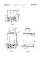
- FIG. 1is a front view, with portions removed, of a multicolor liquid ink jet print head
- FIG. 2is a side view of the print head of FIG. 1, with portions removed;
- FIG. 3is an exploded view of the print head of FIG. 1;
- FIG. 4is a top view of the print head of FIG. 1, with portions removed to permit viewing of the ink flow channels in the bottom of the print head body;
- FIG. 5is a bottom view in perspective of a portion of the print head of FIG. 1;
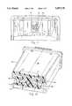
- FIG. 6is a perspective, sectional view of the print head body
- FIG. 7is an enlarged sectional view in perspective of the lower portion of the print head body, viewed from below;
- FIG. 8is an enlarged sectional view in perspective, with portions removed, of the lower portion of the print head body
- FIG. 9is a perspective, sectional view of an alternative form of print head body
- FIG. 10is a top view of the lower portion of the print head body of FIG. 9;
- FIG. 11is a bottom view of the print head body of FIG. 9.
- FIG. 12is a sectional view in perspective of the lower portion of the print head body of FIG. 9 showing the channel structure therein.
- an ink jet print head 10includes a lid 11 and an upper ventilator 12 received beneath the lid on the top of a print head body 13.
- These components of the print headare plastic, with the presently preferred material being a modified polyphenylene oxide, Noryl SE-1 of GE Plastics. The material selected must be moisture resistant and chemically compatible with the components of the ink to be held in the print head body.
- the print head body 13includes interior walls 14 and 16, which serve to divide the body 13 into three interior ink chambers 17, 18, and 19. Each ink chamber 17, 18, and 19 contains a foam block 21, 22 or 23, respectively to hold each of the three colors of ink to be carried in the print head body 13.
- the foam blocksare a reticulated polyether-polyurethane foam, with the presently preferred material being Foamex Corp. SIF Felt No. 03Z70A0532.
- Each of the ink chambers 17, 18, and 19includes in a lower, front portion thereof a chimney, or a stand pipe, 26, 27 or 28, respectively. These stand pipes 26-28 extend slightly above a bottom surface 29 of the ink chambers.
- Each chimney 26, 27, and 28has a disk-shaped filter 30, 31 or 32, respectively, secured on its upper end.
- the filters 30-32are made up of a dynamesh filter medium rated at 20 microns, available from Fluid Dynamics Corp., Deland, Fla.
- a tape automated bonding (TAB) circuit 33is secured with heat and pressure to a side 34 of the print head body 13 as a means to make electrical connections to a thermal ink jet print head chip (not shown), which is located in the area 35 (FIG. 5) on the bottom of the print head body.
- TABtape automated bonding
- Ink of the three colors contained in the print head body 13is supplied to the print head chip through three exit ports in the bottom of the print head body. These exit ports 36, 37, and 38 communicate with the ink chambers 17, 18, and 19, respectively, as shall be described hereinafter.
- Each of the stand pipes 26-28has a main portion tapering slightly (in inside diameter) but substantially cylindrical, with the bottom portions 51-53 of each tapering to a reduced diameter bottom opening 41, 42 or 43, respectively.
- the opening 42 in the bottom of the stand pipe 27communicates with the exit port 37 through a channel 44, which extends substantially downwardly from the opening 42.
- the opening 41 in the bottom of the stand pipe 26communicates with a wide portion 46 of a crossflow channel 47 which in turn is connected to the exit port 36.
- the opening 43 in the bottom of the stand pipe 28communicates with a wide portion 48 of a crossflow channel 49 which is connected to the exit port 38.
- the openings 41 and 43are substantially cylindrical and extend substantially straight downward into the associated crossflow channels.
- the opening 42, the channel 44, and the exit port 37comprise a generally cylindrical structure extending downward.
- the opening 41 in the bottom of the stand pipe 26is generally centrally located in a tapered portion 51 at the bottom of the stand pipe.
- the tapered portion 52 at the bottom of the stand pipe 27angles forwardly to locate the opening 42 toward the front of the print head body 13.
- the tapered portion 53 of the stand pipe 28tapers rearwardly to locate the opening 43 toward the rear of the print head body 13.
- the crossflow channel 47can extend in a straight path behind the channel 44 to terminate at the exit port 36, while the crossflow channel 49 can extend in a straight path behind the line of the crossflow channel 47. Therefore, the various channels do not intersect.
- Each of the stand pipes such as 27includes a pair of ribs such as 54, 55 extending from the inner wall thereof from the top of the stand pipe to the opening 42. These ribs insure the passage of ink downwardly through the various flow paths to the print head chip despite the presence of bubbles in the flow path.
- the print head body 13, with its various ink chambers and flow channels,is conveniently injection molded.
- the molding techniquesare conventional.
- the crossflow channels 46, 47 and 48, 49are formed by retractable side cores, with the mold parting in a direction transverse to the direction of the crossflow channels.
- the openings 41 and 43 in the bottoms of the stand pipes 26 and 28are formed by spring loaded pins in the mold.
- the crossflow channels 46, 47 and 48, 49are sealed at the exterior sides of the print head body 13 by plugs 56 and 57 which are inserted to the openings left by the retractable side cores and ultrasonicly welded therein.
- the plugs 56 and 57are preferably formed of the same Noryl material as the cartridge body 13. In this way the print head body 13 can be molded in a conventional manner, but the ink flow channels are completely separated from one another to avoid mixing of the different inks.
- an alternative, presently preferred, form of print head 60includes a print head body 61 containing, in its lower portion, three standpipe portions 62, 63 and 64.
- Print head 60is substantially the same as the print head 10, except for the standpipe and ink flow structures in the lower portion of the print head body 61.
- standpipes 62, 63 and 64are located in separate ink chambers 66, 67 and 68, respectively.
- the standpipes 62-64extend slightly above a bottom surface 69 of the ink chambers.
- Ink contained in each of the various chambers 66-68 of the print head body 61is supplied to the print head chip through three exit ports in the bottom of the print head body.
- the exit ports 71, 72 and 73communicate with the ink chambers 66, 67 and 68, respectively.
- Each standpipe 62, 63 and 64contains a generally downwardly sloping lower surface 74, 75 and 76.
- An opening 77 in the bottom of the standpipe 62permits ink to flow downwardly into a crossflow channel 81.
- An opening 78 in the bottom of the standpipe 64permits ink to flow downwardly into a crossflow channel 82.
- Ink in the chamber 67flows downwardly through the standpipe 63 directly to the exit port 72.
- the cross channel 81slopes downwardly and forwardly, terminating in a reduced cross-section portion 83 which in turn leads to the exit port 71.
- the cross channel 82slopes downwardly and forwardly to terminate in a reduced cross-section portion 84 and the exit port 73.
- Each of the standpipes such as 63includes a pair of ribs such as 86 and 87 extending from the inner wall thereof.
- the crossflow channels 81 and 82are sealed at their exterior sides by plugs which are ultrasonicly welded therein.
Landscapes
- Particle Formation And Scattering Control In Inkjet Printers (AREA)
- Ink Jet (AREA)
Abstract
Description
Claims (3)
Priority Applications (4)
| Application Number | Priority Date | Filing Date | Title |
|---|---|---|---|
| US08/165,691US5497178A (en) | 1993-12-10 | 1993-12-10 | Multicolor liquid ink jet print head |
| EP94309166AEP0657292B1 (en) | 1993-12-10 | 1994-12-08 | Multicolor liquid ink jet print head |
| DE69405694TDE69405694T2 (en) | 1993-12-10 | 1994-12-08 | Multi-color inkjet printhead |
| US08/537,060US6293664B1 (en) | 1993-12-10 | 1995-09-29 | Multicolor liquid ink jet print head |
Applications Claiming Priority (1)
| Application Number | Priority Date | Filing Date | Title |
|---|---|---|---|
| US08/165,691US5497178A (en) | 1993-12-10 | 1993-12-10 | Multicolor liquid ink jet print head |
Related Child Applications (1)
| Application Number | Title | Priority Date | Filing Date |
|---|---|---|---|
| US08/537,060DivisionUS6293664B1 (en) | 1993-12-10 | 1995-09-29 | Multicolor liquid ink jet print head |
Publications (1)
| Publication Number | Publication Date |
|---|---|
| US5497178Atrue US5497178A (en) | 1996-03-05 |
Family
ID=22600036
Family Applications (2)
| Application Number | Title | Priority Date | Filing Date |
|---|---|---|---|
| US08/165,691Expired - LifetimeUS5497178A (en) | 1993-12-10 | 1993-12-10 | Multicolor liquid ink jet print head |
| US08/537,060Expired - LifetimeUS6293664B1 (en) | 1993-12-10 | 1995-09-29 | Multicolor liquid ink jet print head |
Family Applications After (1)
| Application Number | Title | Priority Date | Filing Date |
|---|---|---|---|
| US08/537,060Expired - LifetimeUS6293664B1 (en) | 1993-12-10 | 1995-09-29 | Multicolor liquid ink jet print head |
Country Status (3)
| Country | Link |
|---|---|
| US (2) | US5497178A (en) |
| EP (1) | EP0657292B1 (en) |
| DE (1) | DE69405694T2 (en) |
Cited By (23)
| Publication number | Priority date | Publication date | Assignee | Title |
|---|---|---|---|---|
| US5659345A (en)* | 1994-10-31 | 1997-08-19 | Hewlett-Packard Company | Ink-jet pen with one-piece pen body |
| USD392672S (en) | 1996-10-16 | 1998-03-24 | Canon Kabushiki Kaisha | Combined ink tank holder and printing head for printer |
| USD395669S (en) | 1996-06-27 | 1998-06-30 | Xerox Corporation | Combined print head and ink tank holder |
| USD395670S (en) | 1996-10-16 | 1998-06-30 | Canon Kabushiki Kaisha | Combined ink tank holder and printing head for printer |
| USD395916S (en) | 1996-10-16 | 1998-07-07 | Canon Kabushiki Kaisha | Combined ink tank holder and printing head for printer |
| EP0887189A2 (en) | 1997-06-26 | 1998-12-30 | Lexmark International, Inc. | Ink-jet print cartridge body |
| USD410948S (en)* | 1997-08-27 | 1999-06-15 | Tektronix, Inc. | Cassette tray |
| US5926195A (en)* | 1996-11-22 | 1999-07-20 | Lexmark International Inc. | Ink jet printhead cartridge |
| US6260961B1 (en) | 2000-03-02 | 2001-07-17 | Hewlett-Packard Company | Unitary one-piece body structure for ink-jet cartridge |
| US20020167574A1 (en)* | 1998-05-18 | 2002-11-14 | Satoshi Shinada | Ink-jet printing apparatus and ink cartridge therefor |
| US20040066433A1 (en)* | 2002-10-02 | 2004-04-08 | Pingrey Brent N. | Side plug for an ink-jet cartridge, and cartridge assembly methods |
| US20040095447A1 (en)* | 2002-11-19 | 2004-05-20 | Bailey Thomas Allen | Multi-color ink reservoirs for ink jet printers |
| US20040201653A1 (en)* | 2003-04-09 | 2004-10-14 | Der-Rong Shyu | Inkjet cartridge |
| US6846063B2 (en) | 2001-12-17 | 2005-01-25 | Lexmark International, Inc. | Chimney for preventing ink misting |
| US6851800B1 (en) | 2003-07-29 | 2005-02-08 | Hewlett-Packard Development Company, L.P. | Print cartridge bodies |
| WO2005102713A1 (en)* | 2004-04-13 | 2005-11-03 | Lexmark International, Inc. | Ink conduit plugs for an inkjet printhead and methods of laser welding same |
| US20060114304A1 (en)* | 2004-11-29 | 2006-06-01 | Lexmark International, Inc. | Air funneling inkjet printhead |
| US20060125892A1 (en)* | 2004-12-10 | 2006-06-15 | Lexmark International, Inc. | Inkjet printhead with bubble handling properties |
| US20070268345A1 (en)* | 2006-05-19 | 2007-11-22 | International United Technology Co., Ltd. | Ink cartridge |
| EP1859944A1 (en) | 2006-05-26 | 2007-11-28 | International United Technology Co., Ltd. | Ink cartridge assembled from body and channel-module |
| US20080024570A1 (en)* | 2006-07-26 | 2008-01-31 | Studer Anthony D | Print cartridge body |
| US8905519B2 (en) | 1999-06-30 | 2014-12-09 | Memjet Technology Ltd. | Inkjet printhead assembly comprising printhead modules having converging ink galleries |
| CN106626783A (en)* | 2015-11-03 | 2017-05-10 | 研能科技股份有限公司 | Multi-color printing ink box |
Families Citing this family (12)
| Publication number | Priority date | Publication date | Assignee | Title |
|---|---|---|---|---|
| JP3177137B2 (en) | 1995-09-29 | 2001-06-18 | キヤノン株式会社 | Ink jet ink cartridge and method of sealing opening of ink jet ink cartridge |
| JPH10235890A (en) | 1996-06-25 | 1998-09-08 | Seiko Epson Corp | ink cartridge |
| US6398344B1 (en)* | 2000-06-30 | 2002-06-04 | Silverbrook Research Pty Ltd | Print head assembly for a modular commercial printer |
| US6971811B2 (en)* | 2002-07-25 | 2005-12-06 | Silverbrook Research Pty Ltd | Print engine having a pair of feed rollers and a print zone proximal thereto |
| JP3666491B2 (en) | 2002-03-29 | 2005-06-29 | セイコーエプソン株式会社 | Ink cartridge and recording apparatus |
| US6969164B2 (en)* | 2003-11-07 | 2005-11-29 | Lexmark International, Inc. | Printing cartridge having a filter tower assembly and process for forming the same |
| KR100571776B1 (en)* | 2004-02-06 | 2006-04-18 | 삼성전자주식회사 | Ink cartridge |
| GB0402655D0 (en)* | 2004-02-06 | 2004-03-10 | Dynamic Cassette Int | An ink container |
| CN100340408C (en)* | 2004-04-01 | 2007-10-03 | 国际联合科技股份有限公司 | Ink box |
| US8029118B2 (en)* | 2005-05-25 | 2011-10-04 | Telecom Italia S.P.A. | Ink jet print cartridge with independent adjacent sealing plugs |
| ES2488815T3 (en) | 2009-03-20 | 2014-08-29 | Clover Technologies Group, Llc | Recycled inkjet printer cartridge, system and procedure |
| GB2470772B (en) | 2009-06-04 | 2011-07-06 | Rue De Int Ltd | Improvements in security substrates |
Citations (3)
| Publication number | Priority date | Publication date | Assignee | Title |
|---|---|---|---|---|
| EP0373302A1 (en)* | 1988-12-16 | 1990-06-20 | Hewlett-Packard Company | Ink jet pen |
| US5025271A (en)* | 1986-07-01 | 1991-06-18 | Hewlett-Packard Company | Thin film resistor type thermal ink pen using a form storage ink supply |
| EP0529879A1 (en)* | 1991-08-29 | 1993-03-03 | Hewlett-Packard Company | Leak resistant ink-jet pen |
Family Cites Families (2)
| Publication number | Priority date | Publication date | Assignee | Title |
|---|---|---|---|---|
| FR2630785B1 (en)* | 1988-05-02 | 1994-02-04 | Institut Francais Petrole | POLYPHASTIC PISTON PUMPING DEVICE AND APPLICATIONS THEREOF |
| JP3148005B2 (en)* | 1992-06-16 | 2001-03-19 | キヤノン株式会社 | Recording cartridge and ink jet recording apparatus |
- 1993
- 1993-12-10USUS08/165,691patent/US5497178A/ennot_activeExpired - Lifetime
- 1994
- 1994-12-08EPEP94309166Apatent/EP0657292B1/ennot_activeExpired - Lifetime
- 1994-12-08DEDE69405694Tpatent/DE69405694T2/ennot_activeExpired - Lifetime
- 1995
- 1995-09-29USUS08/537,060patent/US6293664B1/ennot_activeExpired - Lifetime
Patent Citations (3)
| Publication number | Priority date | Publication date | Assignee | Title |
|---|---|---|---|---|
| US5025271A (en)* | 1986-07-01 | 1991-06-18 | Hewlett-Packard Company | Thin film resistor type thermal ink pen using a form storage ink supply |
| EP0373302A1 (en)* | 1988-12-16 | 1990-06-20 | Hewlett-Packard Company | Ink jet pen |
| EP0529879A1 (en)* | 1991-08-29 | 1993-03-03 | Hewlett-Packard Company | Leak resistant ink-jet pen |
Non-Patent Citations (2)
| Title |
|---|
| Hewlett Packard Journal, Aug. 1992, article entitled Automated Assembly of the HP DeskJet 500C/DeskWriter C Color Print Cartridge by Lee S. Mason and Mark C. Huth, pp. 77 83.* |
| Hewlett-Packard Journal, Aug. 1992, article entitled "Automated Assembly of the HP DeskJet 500C/DeskWriter C Color Print Cartridge" by Lee S. Mason and Mark C. Huth, pp. 77-83. |
Cited By (65)
| Publication number | Priority date | Publication date | Assignee | Title |
|---|---|---|---|---|
| US5659345A (en)* | 1994-10-31 | 1997-08-19 | Hewlett-Packard Company | Ink-jet pen with one-piece pen body |
| US6042225A (en)* | 1994-10-31 | 2000-03-28 | Hewlett-Packard Company | Ink-jet pen with one-piece pen body |
| USD395669S (en) | 1996-06-27 | 1998-06-30 | Xerox Corporation | Combined print head and ink tank holder |
| USD392672S (en) | 1996-10-16 | 1998-03-24 | Canon Kabushiki Kaisha | Combined ink tank holder and printing head for printer |
| USD395670S (en) | 1996-10-16 | 1998-06-30 | Canon Kabushiki Kaisha | Combined ink tank holder and printing head for printer |
| USD395916S (en) | 1996-10-16 | 1998-07-07 | Canon Kabushiki Kaisha | Combined ink tank holder and printing head for printer |
| US5926195A (en)* | 1996-11-22 | 1999-07-20 | Lexmark International Inc. | Ink jet printhead cartridge |
| AU720342B2 (en)* | 1996-11-22 | 2000-05-25 | Funai Electric Co., Ltd. | Ink jet printhead cartridge |
| EP0887189A2 (en) | 1997-06-26 | 1998-12-30 | Lexmark International, Inc. | Ink-jet print cartridge body |
| EP0887189A3 (en)* | 1997-06-26 | 2000-02-02 | Lexmark International, Inc. | Ink-jet print cartridge body |
| USD410948S (en)* | 1997-08-27 | 1999-06-15 | Tektronix, Inc. | Cassette tray |
| US20030085969A1 (en)* | 1998-05-18 | 2003-05-08 | Satoshi Shinada | Ink-jet printing apparatus and ink cartridge therefor |
| US20080284830A1 (en)* | 1998-05-18 | 2008-11-20 | Satoshi Shinada | Ink-jet printing apparatus and ink cartridge therefor |
| US20020171700A1 (en)* | 1998-05-18 | 2002-11-21 | Satoshi Shinada | Ink-jet printing apparatus and ink cartridge therefor |
| US20020180823A1 (en)* | 1998-05-18 | 2002-12-05 | Satoshi Shinada | Ink-jet printing apparatus and ink cartridge therefor |
| US20030058296A1 (en)* | 1998-05-18 | 2003-03-27 | Satoshi Shinada | Ink-jet printing apparatus and ink cartridge therefor |
| US7246882B2 (en) | 1998-05-18 | 2007-07-24 | Seiko Epson Corporation | Ink-jet printing apparatus and ink cartridge therefor |
| US20090040274A1 (en)* | 1998-05-18 | 2009-02-12 | Seiko Epson Corporation | Ink-jet printing apparatus and ink cartridge therefor |
| US20070247501A1 (en)* | 1998-05-18 | 2007-10-25 | Satoshi Shinada | Ink-jet printing apparatus and ink cartridge therefor |
| US7284847B2 (en) | 1998-05-18 | 2007-10-23 | Seiko Epson Corporation | Ink-jet printing apparatus and ink cartridge therefor |
| US7284850B2 (en) | 1998-05-18 | 2007-10-23 | Seiko Epson Corporation | Ink-jet printing apparatus and ink cartridge therefor |
| US7278708B2 (en) | 1998-05-18 | 2007-10-09 | Seiko Epson Corporation | Ink-jet printing apparatus and ink cartridge therefor |
| US20020167574A1 (en)* | 1998-05-18 | 2002-11-14 | Satoshi Shinada | Ink-jet printing apparatus and ink cartridge therefor |
| US7275810B2 (en) | 1998-05-18 | 2007-10-02 | Seiko Epson Corporation | Ink-jet printing apparatus and ink cartridge therefor |
| US20050146576A1 (en)* | 1998-05-18 | 2005-07-07 | Satoshi Shinada | Ink-jet printing apparatus and ink cartridge therefor |
| US20090040275A1 (en)* | 1998-05-18 | 2009-02-12 | Seiko Epson Corporation | Ink-jet printing apparatus and ink cartridge therefor |
| US7264334B2 (en) | 1998-05-18 | 2007-09-04 | Seiko Epson Corporation | Ink-jet printing apparatus and ink cartridge therefor |
| US7252375B2 (en) | 1998-05-18 | 2007-08-07 | Seiko Epson Corporation | Ink-jet printing apparatus and ink cartridge therefor |
| US7510273B2 (en) | 1998-05-18 | 2009-03-31 | Seiko Epson Corporation | Ink-jet printing apparatus and ink cartridge therefor |
| US20060119677A1 (en)* | 1998-05-18 | 2006-06-08 | Satoshi Shinada | Ink-jet printing apparatus and ink cartridge therefor |
| US7954934B2 (en) | 1998-05-18 | 2011-06-07 | Seiko Epson Corporation | Ink-jet printing apparatus and ink cartridge therefor |
| US20090009560A1 (en)* | 1998-05-18 | 2009-01-08 | Seiko Epson Corporation | Ink-jet printing apparatus and ink cartridge therefor |
| US20060203050A1 (en)* | 1998-05-18 | 2006-09-14 | Satoshi Shinada | Ink-jet printing apparatus and ink cartridge therefor |
| US7669969B2 (en) | 1998-05-18 | 2010-03-02 | Seiko Epson Corporation | Ink-jet printing apparatus and ink cartridge therefor |
| US7219985B2 (en) | 1998-05-18 | 2007-05-22 | Seiko Epson Corporation | Ink-jet printing apparatus and ink cartridge therefor |
| US9168755B2 (en) | 1999-06-30 | 2015-10-27 | Memjet Technology Ltd. | Inkjet printhead assembly |
| US8905519B2 (en) | 1999-06-30 | 2014-12-09 | Memjet Technology Ltd. | Inkjet printhead assembly comprising printhead modules having converging ink galleries |
| US9085148B2 (en) | 1999-06-30 | 2015-07-21 | Memjet Technology Ltd. | Inkjet printhead assembly |
| US9539819B2 (en) | 1999-06-30 | 2017-01-10 | Mernjet Technology Limited | Inkjet printhead assembly including slotted shield plate |
| US6260961B1 (en) | 2000-03-02 | 2001-07-17 | Hewlett-Packard Company | Unitary one-piece body structure for ink-jet cartridge |
| US6846063B2 (en) | 2001-12-17 | 2005-01-25 | Lexmark International, Inc. | Chimney for preventing ink misting |
| US6733118B2 (en)* | 2002-10-02 | 2004-05-11 | Hewlett-Packard Development Company, L.P. | Side plug for an ink-jet cartridge, and cartridge assembly methods |
| US20040066433A1 (en)* | 2002-10-02 | 2004-04-08 | Pingrey Brent N. | Side plug for an ink-jet cartridge, and cartridge assembly methods |
| US6984031B2 (en) | 2002-11-19 | 2006-01-10 | Lexmark International, Inc. | Method for making multi-color ink reservoirs for ink jet printers |
| US20050185037A1 (en)* | 2002-11-19 | 2005-08-25 | Lexmark International, Inc. | Method for making multi-color ink reservoirs for ink jet printers |
| US6893120B2 (en) | 2002-11-19 | 2005-05-17 | Lexmark International, Inc. | Multi-color ink reservoirs for ink jet printers |
| US20040095447A1 (en)* | 2002-11-19 | 2004-05-20 | Bailey Thomas Allen | Multi-color ink reservoirs for ink jet printers |
| US7063411B2 (en)* | 2003-04-09 | 2006-06-20 | Benq Corporation | Inkjet cartridge |
| DE102004011226B4 (en)* | 2003-04-09 | 2007-08-02 | Benq Corp., Kweishan | ink cartridge |
| US20040201653A1 (en)* | 2003-04-09 | 2004-10-14 | Der-Rong Shyu | Inkjet cartridge |
| US6851800B1 (en) | 2003-07-29 | 2005-02-08 | Hewlett-Packard Development Company, L.P. | Print cartridge bodies |
| WO2005102713A1 (en)* | 2004-04-13 | 2005-11-03 | Lexmark International, Inc. | Ink conduit plugs for an inkjet printhead and methods of laser welding same |
| CN100393522C (en)* | 2004-04-13 | 2008-06-11 | 莱克斯马克国际公司 | Ink conduit plug of ink jet printing head and laser welding method thereof |
| US7273275B2 (en) | 2004-11-29 | 2007-09-25 | Lexmark International, Inc. | Air funneling inkjet printhead |
| US20060114304A1 (en)* | 2004-11-29 | 2006-06-01 | Lexmark International, Inc. | Air funneling inkjet printhead |
| US7201476B2 (en) | 2004-12-10 | 2007-04-10 | Lexmark International, Inc. | Inkjet printhead with bubble handling properties |
| US20060125892A1 (en)* | 2004-12-10 | 2006-06-15 | Lexmark International, Inc. | Inkjet printhead with bubble handling properties |
| US8025377B2 (en)* | 2006-05-19 | 2011-09-27 | International United Technology Co., Ltd. | Ink cartridge |
| US20070268345A1 (en)* | 2006-05-19 | 2007-11-22 | International United Technology Co., Ltd. | Ink cartridge |
| EP1859944A1 (en) | 2006-05-26 | 2007-11-28 | International United Technology Co., Ltd. | Ink cartridge assembled from body and channel-module |
| US7712883B2 (en) | 2006-07-26 | 2010-05-11 | Hewlett-Packard Development Company, L.P. | Print cartridge body |
| CN101495317B (en)* | 2006-07-26 | 2012-06-27 | 惠普开发有限公司 | Print cartridge body |
| US20080024570A1 (en)* | 2006-07-26 | 2008-01-31 | Studer Anthony D | Print cartridge body |
| CN106626783A (en)* | 2015-11-03 | 2017-05-10 | 研能科技股份有限公司 | Multi-color printing ink box |
| CN106626783B (en)* | 2015-11-03 | 2018-07-03 | 研能科技股份有限公司 | Multi-color print cartridges |
Also Published As
| Publication number | Publication date |
|---|---|
| EP0657292A1 (en) | 1995-06-14 |
| DE69405694T2 (en) | 1998-04-02 |
| DE69405694D1 (en) | 1997-10-23 |
| US6293664B1 (en) | 2001-09-25 |
| EP0657292B1 (en) | 1997-09-17 |
Similar Documents
| Publication | Publication Date | Title |
|---|---|---|
| US5497178A (en) | Multicolor liquid ink jet print head | |
| US6331054B1 (en) | Unitary one-piece body structure for ink-jet cartridge | |
| US5831653A (en) | Ink jet print head cartridge | |
| ES2204725T3 (en) | TECHNIQUES TO PROVIDE CARTRIDGES OF INK JET WITH UNIVERSAL BODY STRUCTURE. | |
| US6042225A (en) | Ink-jet pen with one-piece pen body | |
| EP2043869B1 (en) | Print cartridge | |
| KR930021394A (en) | Ink Supply Unit for Inkjet Printheads | |
| JP3019768B2 (en) | Ink jet printer and ink jet recording unit | |
| US6543887B2 (en) | Inkjet print head | |
| KR100744626B1 (en) | Ink jet head unit and printer incorporating the same | |
| KR100571776B1 (en) | Ink cartridge | |
| KR100503082B1 (en) | Ink cartridge for ink jet printer | |
| JPH0364311B2 (en) | ||
| EP0887189A2 (en) | Ink-jet print cartridge body | |
| EP1896262B1 (en) | Ink-jet print cartridge with independent adjacent sealing plugs | |
| JP3207199U (en) | ink cartridge | |
| US20250010627A1 (en) | Cartridge and printing apparatus | |
| JP2003025562A (en) | Ink jet recording head | |
| JPH0530921Y2 (en) | ||
| KR20050072544A (en) | Ink-cartridge | |
| KR20060020052A (en) | Inkjet Cartridge and Manufacturing Method Thereof | |
| JPS60259459A (en) | Ink jet recording head |
Legal Events
| Date | Code | Title | Description |
|---|---|---|---|
| AS | Assignment | Owner name:LEXMARK INTERNATIONAL, INC., CONNECTICUT Free format text:ASSIGNMENT OF ASSIGNORS INTEREST;ASSIGNORS:DEFOSSE, STEPHEN F.;PHATAK, GANESH V.;SAUERS, MATTHEW C.;REEL/FRAME:006838/0107 Effective date:19940114 | |
| AS | Assignment | Owner name:J.P. MORGAN DELAWARE, AS SECURITY AGENT, DELAWARE Free format text:SECURITY INTEREST;ASSIGNOR:LEXMARK INTERNATIONAL, INC.;REEL/FRAME:007558/0568 Effective date:19950421 | |
| STCF | Information on status: patent grant | Free format text:PATENTED CASE | |
| AS | Assignment | Owner name:LEXMARK INTERNATIONAL, INC., KENTUCKY Free format text:TERMINATION AND RELEASE OF SECURITY INTEREST;ASSIGNOR:MORGAN GUARANTY TRUST COMPANY OF NEW YORK;REEL/FRAME:009490/0176 Effective date:19980127 | |
| FPAY | Fee payment | Year of fee payment:4 | |
| FEPP | Fee payment procedure | Free format text:PAYOR NUMBER ASSIGNED (ORIGINAL EVENT CODE: ASPN); ENTITY STATUS OF PATENT OWNER: LARGE ENTITY | |
| FPAY | Fee payment | Year of fee payment:8 | |
| FPAY | Fee payment | Year of fee payment:12 | |
| REMI | Maintenance fee reminder mailed | ||
| AS | Assignment | Owner name:FUNAI ELECTRIC CO., LTD, JAPAN Free format text:ASSIGNMENT OF ASSIGNORS INTEREST;ASSIGNORS:LEXMARK INTERNATIONAL, INC.;LEXMARK INTERNATIONAL TECHNOLOGY, S.A.;REEL/FRAME:030416/0001 Effective date:20130401 |