US5496290A - Wound irrigation splash shield - Google Patents
Wound irrigation splash shieldDownload PDFInfo
- Publication number
- US5496290A US5496290AUS08/344,728US34472894AUS5496290AUS 5496290 AUS5496290 AUS 5496290AUS 34472894 AUS34472894 AUS 34472894AUS 5496290 AUS5496290 AUS 5496290A
- Authority
- US
- United States
- Prior art keywords
- splash shield
- region
- planar region
- outer concave
- irrigating device
- Prior art date
- Legal status (The legal status is an assumption and is not a legal conclusion. Google has not performed a legal analysis and makes no representation as to the accuracy of the status listed.)
- Expired - Fee Related
Links
Images


Classifications
- A—HUMAN NECESSITIES
- A61—MEDICAL OR VETERINARY SCIENCE; HYGIENE
- A61M—DEVICES FOR INTRODUCING MEDIA INTO, OR ONTO, THE BODY; DEVICES FOR TRANSDUCING BODY MEDIA OR FOR TAKING MEDIA FROM THE BODY; DEVICES FOR PRODUCING OR ENDING SLEEP OR STUPOR
- A61M3/00—Medical syringes, e.g. enemata; Irrigators
- A61M3/02—Enemata; Irrigators
- A61M3/0279—Cannula; Nozzles; Tips; their connection means
- A—HUMAN NECESSITIES
- A61—MEDICAL OR VETERINARY SCIENCE; HYGIENE
- A61B—DIAGNOSIS; SURGERY; IDENTIFICATION
- A61B90/00—Instruments, implements or accessories specially adapted for surgery or diagnosis and not covered by any of the groups A61B1/00 - A61B50/00, e.g. for luxation treatment or for protecting wound edges
- A61B90/05—Splash shields for protection of the surgeon, e.g. splash guards connected to the apparatus
Definitions
- the present inventionrelates to medical shield devices that protect medical personnel from patient body secretions that splash back during wound irrigation. More particularly, the present invention relates to transparent guards that couple directly to such wound irrigating devices.
- Irrigation of woundsis a commonly used method by medical personnel to cleanse wounds of unwanted foreign matter.
- the irrigationis performed using a disposable syringe and hypodermic needle. Fluid from the syringe is directed under pressure at the wound to dislodge contaminates.
- the cleansing action necessary to rid the wound of unwanted contaminatescreates a splashback of fluids and may also form an aerosol containing both the irrigating fluid and blood droplets. This splashback is undesirable because the medical personnel carrying out the irrigation can be exposed to contaminants contained in the patient's blood.
- U.S. Pat. No. 4,769,003, to Stamler entitled WOUND IRRIGATION SPLASHBACK SHIELDdiscloses a device which attempts to contain the splashback by employing an elongated parabolic shield.
- the shieldattaches to a syringe which is inserted into the apex of the parabolic shield.
- the shieldis elongated to a length of 12 cm from the apex of the shield to its rim.
- the Stamler patentstates the device should be used with the rim of the shield 1 cm to 3 cm from the wound. This requires the irrigation stream to travel the length of the shield and the gap between the shield and the wound in order to cleanse the wound.
- the disadvantage of this deviceis that medical personnel cannot get close to the wound to perform the irrigation or to irrigate from the inside of the wound, which is often desirable and necessary.
- the Stamler patentillustrates the effectiveness of the device when the irrigation takes place at a very small angle of incidence to the wound site. During an irrigation procedure, there often occurs a situation where it is desirable to deliver the irrigation fluid at a large angle of incidence to the wound site. It appears in this situation as if the irrigation fluid will splashback in a manner such that the shield will not prevent the fluids from contacting other medical personnel at the surgical site.
- U.S. Pat. No. 4,692,140, to Olson entitled LAVAGE/SUCTION TIP WITH DUAL SPLASH SHIELDdiscloses a device which includes an elongated barrel to deliver fluid and a pair of splash shields. This device is attached to a corresponding handpiece which supplies the irrigation fluid. The first splash shield is bonded to the distal end of the barrel of the device. The second shield is slidable along the barrel to a position chosen by the person performing the irrigation. This device has the splash shields directly incorporated onto the barrel. It appears that commonly used surgical equipment to irrigate wounds, such as syringes, cannot be used in conjunction with this device. This requires those who may wish to use this device to irrigate wounds to purchase the entire device.
- the Olson patentstates that the first splash shield is preferably sized with a diameter of 11/4 inches.
- the diameter of the first splash shieldlimits the usefulness of the device to small wound sites.
- the Olson patentdid not disclose a diameter for the second splash shield, but it appears to be roughly the same size as the first splash shield. The small size of the second splash shield may not provide adequate protection against fluid splashback.
- the prior artdemonstrates there is a need for a splash shield which is easily attached to existing medical equipment, that effectively contains the fluids which splash back and is constructed at a relatively low cost.
- the present inventionincorporates several features and advantages to overcome the deficiencies of the prior art.
- the present inventionis a device for the prevention of contamination of medical personnel from a patient's body secretions that may splash back during wound irrigation.
- the splash shieldis substantially circular and made of a transparent, rigid material.
- the splash shieldhas a flat center region encircled by an outer concave region and a hollow conical protrusion adapted to receive the tip of a syringe.
- the flat center regionis substantially circular and forms the middle of the splash shield. Moving radially outward from the flat center region is a concentrically located outer concave region which encircles the flat center region. The outer concave region curves in a direction toward the patient.
- the conical protrusionis eccentrically located in the flat center region of the splash shield.
- the conical protrusionis hollow defining a circle through which the tip of a syringe may pass.
- the conical protrusionis dimensioned such that a friction fit is created between the interior of the conical protrusion and the end of the syringe when inserted therein.
- FIG. 1is a perspective view of the first embodiment of the present invention
- FIG. 2is a cross-sectional view of the embodiment of FIG. 1, viewed along section line 1--1;
- FIG. 3is an perspective view of the first embodiment of the present invention attached to the tip or end of a syringe member
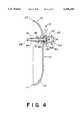
- FIG. 4is a cross-sectional view of the second embodiment as viewed along section line 1--1 of FIG. 1.
- the splash shield 10has a peripheral edge 22 that is substantially circular with a diameter D1.
- the splash shield 10is made of a transparent, rigid material, such as plastic or glass.
- the splash shield 10has a flat center region 12 encircled by an outer concave region 14.
- a hollow conical protrusion 16extends through the splash shield at a point eccentric to its center. The purpose of the hollow conical protrusion will later be described.
- the flat center region 12is substantially circular and forms the middle of the splash shield 10. Moving radially outward from the flat center region 12 is a concentrically located outer concave region 14 which encircles the flat center region 12. The outer concave region 14 curves away from the flat center region 12, thereby providing the splash shield 10 with an overall width W1.
- a peripheral edge 22is located at the rim of the outer concave region 14. The peripheral edge 22 is flat and extends outwardly from the outer concave region 14 in a plane substantially parallel to the flat center region 12.
- the conical protrusion 16is eccentrically located in the flat center region 12 of the splash shield 10.
- the conical protrusion 16has a base 24 of a first diameter D2 that lays flush against the flat center region 12. As the conical protrusion 16 extends away from the flat center region 12, it tapers down to a second diameter D3 at its top surface 26.
- the height H1 of the conical protrusion 16is defined by the distance between the base 24 and the top surface 26.
- the height H1 of the conical protrusion 16is preferably less than the width W1 of the splash shield 10. Moving along the conical protrusion 16 from the base to the top surface, an aperture 20 is defined by the cross-sectional diameter of the conical protrusion 16 which decreases in length.
- the cross-sectional diameter of the aperture 20 defined by the conical protrusion 16is dimensioned such that a friction fit is created between the interior of the conical protrusion 16 and the end of a syringe when inserted therein.
- a syringe 30is shown in conjunction with the splash shield 10.
- the tip or end of the syringeis coupled to a dual check valve which is known in the art and provided by the assignee herein.
- the distal end of the check valveincorporates a flexible tip.
- other devices or terminationscan be conventionally positioned on the end of the syringe or the end or tip of the syringe may accommodate the shield directly. In this manner, the tip or end of the syringe member may be flexible or rigid.
- the term syringe tip or endrefers to the location which is accommodating the shield 10.
- the syringe 30is coupled to a flexible irrigation tip associated with the check valve 32 that directs fluid discharged by the syringe 30.
- the syringe 30is attached to the splash shield 10 by inserting the flexible tip 32 into the conical protrusion 16.
- a portion 17 of the tip 32passes through the aperture 20 of the conical protrusion 16 such that the portion 17 of the flexible tip 32 extends beyond the conical protrusion 16 and the peripheral edge 22.
- the flexible tip 32is tapered and creates a friction fit with the aperture 20 defined by the conical protrusion 16 as the flexible tip 32 is advanced within the conical protrusion 16.
- the flexible tip 32is then placed in close proximity to or inside the wound site 38 to be irrigated.
- the portion 17 of the flexible tip 32 that passes through the conical protrusion 16is the closest part of the syringe to the wound site 38.
- the splash shield 10can be rotated about the flexible tip 32 to maximize the coverage of the wound site 38 and create the greatest level of protection from fluids splashing back.
- the irrigation fluidpasses through the flexible tip 32 and irrigates the wound site 38.
- the irregularities of the surface of the wound site 38causes the irrigation fluid to rebound from the wound site 38 in an unpredictable direction creating potentially infectious splashback.
- the curvature of the outer concave region 14 of the splash shield 10directs the accumulated splashback towards the center of the splash shield 10. The splashback runs downward and drips harmlessly from the bottom of the splash shield 10.
- the outer concave region 14 of the splash shield 10acts as a catch basin that guides the splash back fluid to the bottom most point P of the splash shield 10.
- the splash shield 10is designed to be used in conjunction with a flexible tip attached to the syringe.
- the present inventionis preferably packaged sterile and manufactured such that it is cost effective to be used once and discarded. Because the preset invention is designed to be used in conjunction with a flexible tip, the person performing the irrigation does not need to worry about accidentally contacting the sharp hypodermic needle of an ordinary syringe. The flexible tip prevents accidental exposure to disease that an ordinary hypodermic needle cannot.
- the splash shield 10has a flat center region 12 encircled by an outer concave region 14 and a conical protrusion 16 eccentrically located about the midpoint of the splash shield 10.
- the flat center region 12, the outer concave region 14 and the conical protrusion 16are similar to those in the first embodiment and are thus identified with the same reference numbers.
- the splash shield 10includes a flexible tip 64 to direct the irrigation stream and a cylindrical hub 52 to attach the splash shield 10 to an irrigating device.
- the cylindrical hub 52has a base 54, a ridge 56 and a top surface 58.
- the base 54has a first diameter D4 and is capable of connecting to an irrigating device.
- the cross-sectional diameter of the cylindrical hub 52 between the base 54 and the top surface 58defines an aperture 62.
- the portion of the aperture 62 defined. by the cross-sectional diameter of the cylindrical hub 52 between the base 54 and the ridge 56is dimensioned such that a friction fit is created between the interior of the cylindrical hub 52 and the tapered tip of a syringe when inserted therein.
- the cylindrical hub 52Extending along the cylindrical hub 52 from the ridge 56 to the top surface 58, the cylindrical hub 52 has a substantially constant cross-sectional diameter D6 which is smaller than the diameter D5 of the ridge 56.
- the base 54 of the cylindrical hub 52is encircled by an annular flange 60 which extends radially outward from the outer surface of the cylindrical hub 52.
- the diameter of the flange 60is sized such that the flange 60 is capable of engaging the threaded tip of a syringe.
- the flexible tip 64has a input end 66 of a diameter D7 and an output end 68.
- the flexible tip 64is tapered and defines an aperture 70 which narrows moving from the input end 66 and the output end 68.
- the diameter of the aperture 70is dimensioned such that a friction fit is created as the top surface 58 of the cylindrical hub 52 is inserted into the input end 66 of the flexible tip 64.
- the ridge 56acts as a stop to prevent the cylindrical hub 52 from being inserted too far into the flexible tip 64.
- the flexible tip 64is attached to the splash shield 10 by a friction fit with the conical protrusion 16 created as the flexible tip 64 is advanced within the conical protrusion 16. It may be desirable to adhere the flexible tip 64 to the interior surface of the conical protrusion 16 to further secure the flexible tip 64 to the splash shield 10.
- a syringe with either a tapered tip or threaded tipengages the base 54 of the cylindrical hub 52. If a syringe with a tapered tip is used, the tapered tip creates a friction fit with the cylindrical hub 52 as the tapered tip is advanced within the aperture 62. Depending upon the angle of the syringe relative to the wound site, the splash shield 10 can be rotated about the tapered tip of the syringe to maximize the coverage of the wound site to be irrigated. If a syringe with a threaded tip is used, the threaded end of the syringe engage the flange 60 encircling the base 54 of the cylindrical hub 52.
- the threaded-tipped syringe and the splash shield 10must be rotated together in order to maximize the coverage of the wound site.
- the advantage of this embodimentis that when the splash shield is used in conjunction with a threaded-tipped syringe, there is a minimal risk of the splash shield disengaging from the syringe.
- This embodimentoperates similarly as the first embodiment once the splash shield 10 is connected to the syringe and the wound site is protected.
- the flexible tip 64is placed in close proximity to the wound site to be irrigated. By pressing on the plunger of the syringe, the irrigation fluid passes through the flexible tip 64 and irrigates the wound site.
- the curvature of the outer concave region 14 of the splash shield 10directs the accumulated splashback towards the center of the splash shield 10. The splashback runs downward and drips harmlessly from the bottom of the splash shield 10.
- the outer concave region 14 of the splash shield 10acts as a catch basin the guides the splashback fluid to the bottom most point P of the splash shield 10.
- the diameter D1 of the splash shield and the radius of curvature of the outer concave regioncan vary depending upon the application.
- the conical protrusioncan define an aperture of any size depending upon the size of the flexible tip used for irrigation.
- the conical protrusionmay be eccentrically located anywhere on the splash shield.
Landscapes
- Health & Medical Sciences (AREA)
- Life Sciences & Earth Sciences (AREA)
- General Health & Medical Sciences (AREA)
- Veterinary Medicine (AREA)
- Heart & Thoracic Surgery (AREA)
- Surgery (AREA)
- Biomedical Technology (AREA)
- Animal Behavior & Ethology (AREA)
- Engineering & Computer Science (AREA)
- Public Health (AREA)
- Anesthesiology (AREA)
- Nuclear Medicine, Radiotherapy & Molecular Imaging (AREA)
- Oral & Maxillofacial Surgery (AREA)
- Pathology (AREA)
- Hematology (AREA)
- Medical Informatics (AREA)
- Molecular Biology (AREA)
- Infusion, Injection, And Reservoir Apparatuses (AREA)
Abstract
Description
The present invention relates to medical shield devices that protect medical personnel from patient body secretions that splash back during wound irrigation. More particularly, the present invention relates to transparent guards that couple directly to such wound irrigating devices.
Irrigation of wounds is a commonly used method by medical personnel to cleanse wounds of unwanted foreign matter. Typically, the irrigation is performed using a disposable syringe and hypodermic needle. Fluid from the syringe is directed under pressure at the wound to dislodge contaminates. The cleansing action necessary to rid the wound of unwanted contaminates creates a splashback of fluids and may also form an aerosol containing both the irrigating fluid and blood droplets. This splashback is undesirable because the medical personnel carrying out the irrigation can be exposed to contaminants contained in the patient's blood.
A great concern of medical personnel is the possible transmission of infectious disease during the irrigation process. This occurs primarily through the fluids which splash back. It is impossible for medical personnel to visually determine if blood from a wound site is carrying infectious diseases such as hepatitis or HIV. Although goggles and facemasks will protect the wearer, those who are unprotected may fall victim to a disease transmitted in the splashback.
There have been many attempts in the prior art to contain the splashback, but none have proven to be completely effective.
Another possibility of transmission of infectious disease exists when the person performing the irrigation is accidentally pierced by the hypodermic needle of the syringe. Splashback may contact the hypodermic needle as the irrigation is performed. As the supply of irrigating fluid is exhausted, which takes a matter of seconds, it must be refilled. This necessitates that the syringe be refilled several times while performing a typical irrigation. Each time the syringe is filled there is a chance of an accidental contact with the hypodermic needle. Thus, the greater the number of times the syringe is refilled, the higher the probability that the person performing the irrigation will contact the hypodermic needle and possibly contact an infectious disease.
Flat, circular splash shields have been utilized in the prior art with irrigation devices for the purpose of preventing the fluids from splashing back toward the irrigating device. These types of devices are typically thin pieces of plastic through which is formed an aperture. This type of splash shield is designed to protect the person performing the :irrigation from splashback, but does not adequately protect others at the surgical site from contamination. A disadvantage of this type of splash shield is inherent in the flat surface and a poor frictional gripping aperture which may cause the shield to dislodge. Should the splash shield separate from the flexible tip, the splash shield would provide no protection whatsoever to the person performing the irrigation.
U.S. Pat. No. 4,769,003, to Stamler entitled WOUND IRRIGATION SPLASHBACK SHIELD, discloses a device which attempts to contain the splashback by employing an elongated parabolic shield. The shield attaches to a syringe which is inserted into the apex of the parabolic shield. In the preferred embodiment, the shield is elongated to a length of 12 cm from the apex of the shield to its rim. The Stamler patent states the device should be used with the rim of the shield 1 cm to 3 cm from the wound. This requires the irrigation stream to travel the length of the shield and the gap between the shield and the wound in order to cleanse the wound. The disadvantage of this device is that medical personnel cannot get close to the wound to perform the irrigation or to irrigate from the inside of the wound, which is often desirable and necessary. The Stamler patent illustrates the effectiveness of the device when the irrigation takes place at a very small angle of incidence to the wound site. During an irrigation procedure, there often occurs a situation where it is desirable to deliver the irrigation fluid at a large angle of incidence to the wound site. It appears in this situation as if the irrigation fluid will splashback in a manner such that the shield will not prevent the fluids from contacting other medical personnel at the surgical site.
U.S. Pat. No. 4,692,140, to Olson entitled LAVAGE/SUCTION TIP WITH DUAL SPLASH SHIELD discloses a device which includes an elongated barrel to deliver fluid and a pair of splash shields. This device is attached to a corresponding handpiece which supplies the irrigation fluid. The first splash shield is bonded to the distal end of the barrel of the device. The second shield is slidable along the barrel to a position chosen by the person performing the irrigation. This device has the splash shields directly incorporated onto the barrel. It appears that commonly used surgical equipment to irrigate wounds, such as syringes, cannot be used in conjunction with this device. This requires those who may wish to use this device to irrigate wounds to purchase the entire device. This may increase costs to hospitals. The Olson patent states that the first splash shield is preferably sized with a diameter of 11/4 inches. The diameter of the first splash shield limits the usefulness of the device to small wound sites. The Olson patent did not disclose a diameter for the second splash shield, but it appears to be roughly the same size as the first splash shield. The small size of the second splash shield may not provide adequate protection against fluid splashback.
The prior art demonstrates there is a need for a splash shield which is easily attached to existing medical equipment, that effectively contains the fluids which splash back and is constructed at a relatively low cost. The present invention incorporates several features and advantages to overcome the deficiencies of the prior art.
The present invention is a device for the prevention of contamination of medical personnel from a patient's body secretions that may splash back during wound irrigation. The splash shield is substantially circular and made of a transparent, rigid material. The splash shield has a flat center region encircled by an outer concave region and a hollow conical protrusion adapted to receive the tip of a syringe.
The flat center region is substantially circular and forms the middle of the splash shield. Moving radially outward from the flat center region is a concentrically located outer concave region which encircles the flat center region. The outer concave region curves in a direction toward the patient. The conical protrusion is eccentrically located in the flat center region of the splash shield. The conical protrusion is hollow defining a circle through which the tip of a syringe may pass. The conical protrusion is dimensioned such that a friction fit is created between the interior of the conical protrusion and the end of the syringe when inserted therein.
FIG. 1 is a perspective view of the first embodiment of the present invention;
FIG. 2 is a cross-sectional view of the embodiment of FIG. 1, viewed along section line 1--1;
FIG. 3 is an perspective view of the first embodiment of the present invention attached to the tip or end of a syringe member;
FIG. 4 is a cross-sectional view of the second embodiment as viewed along section line 1--1 of FIG. 1.
Referring to FIGS. 1 and 2, there is illustrated the first embodiment of thesplash shield 10. Thesplash shield 10 has aperipheral edge 22 that is substantially circular with a diameter D1. In the preferred embodiment, thesplash shield 10 is made of a transparent, rigid material, such as plastic or glass. Thesplash shield 10 has aflat center region 12 encircled by an outerconcave region 14. A hollowconical protrusion 16 extends through the splash shield at a point eccentric to its center. The purpose of the hollow conical protrusion will later be described.
Theflat center region 12 is substantially circular and forms the middle of thesplash shield 10. Moving radially outward from theflat center region 12 is a concentrically located outerconcave region 14 which encircles theflat center region 12. The outerconcave region 14 curves away from theflat center region 12, thereby providing thesplash shield 10 with an overall width W1. Aperipheral edge 22 is located at the rim of the outerconcave region 14. Theperipheral edge 22 is flat and extends outwardly from the outerconcave region 14 in a plane substantially parallel to theflat center region 12.
Theconical protrusion 16 is eccentrically located in theflat center region 12 of thesplash shield 10. Theconical protrusion 16 has abase 24 of a first diameter D2 that lays flush against theflat center region 12. As theconical protrusion 16 extends away from theflat center region 12, it tapers down to a second diameter D3 at itstop surface 26. The height H1 of theconical protrusion 16 is defined by the distance between the base 24 and thetop surface 26. The height H1 of theconical protrusion 16 is preferably less than the width W1 of thesplash shield 10. Moving along theconical protrusion 16 from the base to the top surface, anaperture 20 is defined by the cross-sectional diameter of theconical protrusion 16 which decreases in length.
As will be later shown, the cross-sectional diameter of theaperture 20 defined by theconical protrusion 16 is dimensioned such that a friction fit is created between the interior of theconical protrusion 16 and the end of a syringe when inserted therein.
Referring to FIG. 3, a syringe 30 is shown in conjunction with thesplash shield 10. The tip or end of the syringe is coupled to a dual check valve which is known in the art and provided by the assignee herein. The distal end of the check valve incorporates a flexible tip. However, when discussing the syringe tip or end it is understood that reference is generally made to the fluid discharge outlet portion of the syringe or syringe member. It is understood that other devices or terminations can be conventionally positioned on the end of the syringe or the end or tip of the syringe may accommodate the shield directly. In this manner, the tip or end of the syringe member may be flexible or rigid. Therefore, the term syringe tip or end refers to the location which is accommodating theshield 10. The syringe 30 is coupled to a flexible irrigation tip associated with thecheck valve 32 that directs fluid discharged by the syringe 30. The syringe 30 is attached to thesplash shield 10 by inserting theflexible tip 32 into theconical protrusion 16. A portion 17 of thetip 32 passes through theaperture 20 of theconical protrusion 16 such that the portion 17 of theflexible tip 32 extends beyond theconical protrusion 16 and theperipheral edge 22. Theflexible tip 32 is tapered and creates a friction fit with theaperture 20 defined by theconical protrusion 16 as theflexible tip 32 is advanced within theconical protrusion 16. Theflexible tip 32 is then placed in close proximity to or inside thewound site 38 to be irrigated. The portion 17 of theflexible tip 32 that passes through theconical protrusion 16 is the closest part of the syringe to thewound site 38. Depending upon the angle of the syringe 30 relative to thewound site 38, thesplash shield 10 can be rotated about theflexible tip 32 to maximize the coverage of thewound site 38 and create the greatest level of protection from fluids splashing back.
By pressing on theplunger 36 of the syringe 30, the irrigation fluid passes through theflexible tip 32 and irrigates thewound site 38. The irregularities of the surface of thewound site 38 causes the irrigation fluid to rebound from thewound site 38 in an unpredictable direction creating potentially infectious splashback. The curvature of the outerconcave region 14 of thesplash shield 10 directs the accumulated splashback towards the center of thesplash shield 10. The splashback runs downward and drips harmlessly from the bottom of thesplash shield 10. The outerconcave region 14 of thesplash shield 10 acts as a catch basin that guides the splash back fluid to the bottom most point P of thesplash shield 10.
Thesplash shield 10 is designed to be used in conjunction with a flexible tip attached to the syringe. The present invention is preferably packaged sterile and manufactured such that it is cost effective to be used once and discarded. Because the preset invention is designed to be used in conjunction with a flexible tip, the person performing the irrigation does not need to worry about accidentally contacting the sharp hypodermic needle of an ordinary syringe. The flexible tip prevents accidental exposure to disease that an ordinary hypodermic needle cannot.
Referring to FIG. 4, there is illustrated a second embodiment of the present invention. In this embodiment, thesplash shield 10 has aflat center region 12 encircled by an outerconcave region 14 and aconical protrusion 16 eccentrically located about the midpoint of thesplash shield 10. Theflat center region 12, the outerconcave region 14 and theconical protrusion 16 are similar to those in the first embodiment and are thus identified with the same reference numbers. Thesplash shield 10 includes aflexible tip 64 to direct the irrigation stream and acylindrical hub 52 to attach thesplash shield 10 to an irrigating device.
Thecylindrical hub 52 has abase 54, aridge 56 and atop surface 58. Thebase 54 has a first diameter D4 and is capable of connecting to an irrigating device. The cross-sectional diameter of thecylindrical hub 52 between the base 54 and thetop surface 58 defines anaperture 62. As thecylindrical hub 52 extends away from thebase 54, it tapers to aridge 56 of a second diameter D5 located near the midpoint of thecylindrical hub 52. The portion of theaperture 62 defined. by the cross-sectional diameter of thecylindrical hub 52 between the base 54 and theridge 56 is dimensioned such that a friction fit is created between the interior of thecylindrical hub 52 and the tapered tip of a syringe when inserted therein. Extending along thecylindrical hub 52 from theridge 56 to thetop surface 58, thecylindrical hub 52 has a substantially constant cross-sectional diameter D6 which is smaller than the diameter D5 of theridge 56. Thebase 54 of thecylindrical hub 52 is encircled by anannular flange 60 which extends radially outward from the outer surface of thecylindrical hub 52. The diameter of theflange 60 is sized such that theflange 60 is capable of engaging the threaded tip of a syringe.
Theflexible tip 64 has ainput end 66 of a diameter D7 and anoutput end 68. Theflexible tip 64 is tapered and defines anaperture 70 which narrows moving from theinput end 66 and theoutput end 68. The diameter of theaperture 70 is dimensioned such that a friction fit is created as thetop surface 58 of thecylindrical hub 52 is inserted into theinput end 66 of theflexible tip 64. Theridge 56 acts as a stop to prevent thecylindrical hub 52 from being inserted too far into theflexible tip 64. Theflexible tip 64 is attached to thesplash shield 10 by a friction fit with theconical protrusion 16 created as theflexible tip 64 is advanced within theconical protrusion 16. It may be desirable to adhere theflexible tip 64 to the interior surface of theconical protrusion 16 to further secure theflexible tip 64 to thesplash shield 10.
To use this embodiment, a syringe with either a tapered tip or threaded tip engages thebase 54 of thecylindrical hub 52. If a syringe with a tapered tip is used, the tapered tip creates a friction fit with thecylindrical hub 52 as the tapered tip is advanced within theaperture 62. Depending upon the angle of the syringe relative to the wound site, thesplash shield 10 can be rotated about the tapered tip of the syringe to maximize the coverage of the wound site to be irrigated. If a syringe with a threaded tip is used, the threaded end of the syringe engage theflange 60 encircling thebase 54 of thecylindrical hub 52. Depending upon the angle of the syringe relative to the wound site, the threaded-tipped syringe and thesplash shield 10 must be rotated together in order to maximize the coverage of the wound site. The advantage of this embodiment is that when the splash shield is used in conjunction with a threaded-tipped syringe, there is a minimal risk of the splash shield disengaging from the syringe.
This embodiment operates similarly as the first embodiment once thesplash shield 10 is connected to the syringe and the wound site is protected. Theflexible tip 64 is placed in close proximity to the wound site to be irrigated. By pressing on the plunger of the syringe, the irrigation fluid passes through theflexible tip 64 and irrigates the wound site. The curvature of the outerconcave region 14 of thesplash shield 10 directs the accumulated splashback towards the center of thesplash shield 10. The splashback runs downward and drips harmlessly from the bottom of thesplash shield 10. The outerconcave region 14 of thesplash shield 10 acts as a catch basin the guides the splashback fluid to the bottom most point P of thesplash shield 10.
It should be understood that the embodiments described herein are merely exemplary and that a person skilled in the art may make variations and modifications without departing from the spirit and scope of the invention. For example, the diameter D1 of the splash shield and the radius of curvature of the outer concave region can vary depending upon the application. The conical protrusion can define an aperture of any size depending upon the size of the flexible tip used for irrigation. Finally, the conical protrusion may be eccentrically located anywhere on the splash shield.
Claims (16)
1. A splash shield for use in conjunction with a fluid irrigating device having an elongated tip, said splash shield comprising:
a centrally disposed planar region having a midpoint, said centrally disposed planar region merging into an outer concave region which extends radially from said planar region, said outer concave region terminating at a rim;
connecting means located in said planar region and disposed at a point eccentric to said midpoint, for selectively connecting said splash shield to the elongated tip of the fluid irrigating device, wherein the elongated tip projects through said connecting means and extends beyond said rim.
2. The splash shield of claim 1, wherein said planar region and said outer concave region are generally circularly disposed about said midpoint.
3. The splash shield of claim 1, wherein said connecting means defines a tapered lumen through which the elongated tip of the fluid irrigating device may pass.
4. The splash shield of claim 3, wherein said tapered lumen is dimensioned to create a friction fit with the elongated tip of the fluid irrigating device when the elongated tip is inserted through said tapered lumen.
5. The splash shield of claim 1, wherein a first predetermined distance exists between the plane of said rim and said planar region, and said conical protrusion extends from said planar region by a second predetermined distance that is less than said first predetermined distance.
6. The splash shield of claim 1, wherein said planar region and said outer concave region are generally transparent.
7. A splash shield for use in conjunction with a fluid irrigating device, comprising:
a centrally disposed planar region having a midpoint, said planar region having a first surface and an opposite second surface, said centrally disposed planar region merging into an outer concave region which extends radially from said planar region, said outer concave region terminating at a rim;
a flexible tip projecting forward from said first surface to a point beyond said rim; and
a cylindrical hub extending from said second surface of said planar region for receiving the fluid irrigating device and directing fluid from the fluid irrigating device into said flexible tip, wherein said cylindrical hub is disposed at a point eccentric to said midpoint.
8. The splash shield of claim 7, wherein said cylindrical hub defines a tapered lumen through which the tip of the fluid irrigating device may pass.
9. The splash shield of claim 8, wherein said tapered lumen is dimensioned to create a friction fit with the tip of the fluid irrigating device when the tip is inserted through said tapered lumen.
10. The splash shield of claim 7, wherein said cylindrical hub includes an engaging means for mechanically engaging the fluid irrigating device.
11. The splash shield of claim 10, wherein the fluid irrigating device is a syringe and said engaging means includes a thread capable of being threadedly engaged with the syringe.
12. The splash shield of claim 7, wherein said planar region and said outer concave region are generally circularly disposed about said midpoint.
13. The splash shield of claim 7, wherein said planar region and said outer concave region are generally transparent.
14. A method of irrigating a wound site to protect against fluids that splash back comprising the steps of:
providing a transparent splash shield having a centrally disposed planar region having a midpoint, said centrally disposed planar region merging into an outer concave region which extends radially from said planar region and a connecting means located eccentric to said midpoint in said planar region;
attaching an irrigating device source to said connecting means;
placing said splash shield in close proximity to said wound site;
determining the orientation of the irrigating device to properly irrigate the wound site; and
positioning said splash shield in relation to said irrigating device to optimally shield the wound site; and
irrigating said wound site.
15. The method of claim 14, wherein said step of positioning said splash shield further includes the step of:
rotating said splash shield relative to the irrigating device.
16. The method of claim 14, wherein said connecting means defines a tapered lumen dimensioned to create a friction fit with the fluid irrigating device when inserted therein.
Priority Applications (1)
| Application Number | Priority Date | Filing Date | Title |
|---|---|---|---|
| US08/344,728US5496290A (en) | 1994-11-23 | 1994-11-23 | Wound irrigation splash shield |
Applications Claiming Priority (1)
| Application Number | Priority Date | Filing Date | Title |
|---|---|---|---|
| US08/344,728US5496290A (en) | 1994-11-23 | 1994-11-23 | Wound irrigation splash shield |
Publications (1)
| Publication Number | Publication Date |
|---|---|
| US5496290Atrue US5496290A (en) | 1996-03-05 |
Family
ID=23351756
Family Applications (1)
| Application Number | Title | Priority Date | Filing Date |
|---|---|---|---|
| US08/344,728Expired - Fee RelatedUS5496290A (en) | 1994-11-23 | 1994-11-23 | Wound irrigation splash shield |
Country Status (1)
| Country | Link |
|---|---|
| US (1) | US5496290A (en) |
Cited By (78)
| Publication number | Priority date | Publication date | Assignee | Title |
|---|---|---|---|---|
| USD381965S (en)* | 1996-02-02 | 1997-08-05 | Zimmer, Inc. | Splash shield for a lavage tip |
| USD386684S (en)* | 1996-07-16 | 1997-11-25 | Marogil Joseph B | Antiseptic spray nozzle and guard |
| US5913832A (en)* | 1995-09-06 | 1999-06-22 | Inventamed International Inc. | Urine collection system |
| US5941859A (en)* | 1997-03-17 | 1999-08-24 | Lerman; Benjamin S. | Wound irrigation shield with fluid scavenging |
| WO2000006219A1 (en)* | 1998-07-28 | 2000-02-10 | Advanced Therapeutic Technologies At2 Inc. | Wound irrigation device |
| US6050981A (en)* | 1998-05-11 | 2000-04-18 | Merit Medical Systems, Inc. | Wound irrigation system with flexible shield |
| US6093182A (en)* | 1998-05-11 | 2000-07-25 | Merit Medical Systems, Inc. | Wound irrigation shield adaptor |
| US6156004A (en)* | 1996-06-18 | 2000-12-05 | C. R. Bard, Inc. | Suction and irrigation handpiece and tip with retractable splash shield |
| EP1009319A4 (en)* | 1997-09-02 | 2000-12-06 | Canyons International Inc | Wound irrigation apparatus |
| US6319224B1 (en)* | 1999-08-20 | 2001-11-20 | Bioject Medical Technologies Inc. | Intradermal injection system for injecting DNA-based injectables into humans |
| WO2001095957A2 (en) | 2000-06-09 | 2001-12-20 | Abbott Laboratories | Assembly for transferring fluid from a flexible container |
| US6394996B1 (en) | 1997-01-07 | 2002-05-28 | C. R. Bard, Inc. | System for aspirating and irrigating tract wounds |
| US6402724B1 (en) | 1997-09-09 | 2002-06-11 | Wolfe Tory Medical, Inc. | Wound irrigation shield |
| US6485452B1 (en) | 1996-06-18 | 2002-11-26 | C. R. Bard, Inc. | Suction and irrigation handpiece and tip |
| US6558344B2 (en)* | 2001-02-09 | 2003-05-06 | Westmed, Inc. | Wound irrigation device |
| US6695773B1 (en)* | 2001-09-20 | 2004-02-24 | Eric Dahlinger | Surgical instrument fluid shield |
| US20040116903A1 (en)* | 2002-12-11 | 2004-06-17 | Osman Ali Mohammed | Spray pump wound irrigation device |
| US20040215155A1 (en)* | 2003-04-23 | 2004-10-28 | Wolfe Timothy R. | Wound irrigator |
| US20040225266A1 (en)* | 2003-02-11 | 2004-11-11 | Dilip Tapadiya | Suction hose for wound aspiration |
| US20050027239A1 (en)* | 1999-08-20 | 2005-02-03 | Stout Richard R. | Intradermal injection system for injecting DNA-based injectables into humans |
| WO2006114653A1 (en)* | 2005-04-25 | 2006-11-02 | Dolhay Kft | Treatment nozzle |
| US7161203B2 (en) | 2004-06-04 | 2007-01-09 | Micron Technology, Inc. | Gated field effect device comprising gate dielectric having different K regions |
| GB2432122A (en)* | 2005-11-11 | 2007-05-16 | George Virich | Splash shield for wound irrigation apparatus |
| US20070163573A1 (en)* | 2006-01-18 | 2007-07-19 | Act Seed Technology Fund Llc | Wound cleaning and decontamination device and method of use thereof |
| US20070173773A1 (en)* | 2006-01-23 | 2007-07-26 | Keith Stamler | Wound irrigation splashback shield |
| US20100249709A1 (en)* | 2009-03-27 | 2010-09-30 | Tyco Healthcare Group Lp | Surgical access assembly including shield member |
| WO2011162873A1 (en)* | 2010-06-21 | 2011-12-29 | New York Blood Center, Inc. | System and methods for enhanced protection during blood tubing sealing |
| US20120035559A1 (en)* | 2010-08-09 | 2012-02-09 | Rucinski Paul J | Device and Method for Abscess Irrigation |
| US20120116409A1 (en)* | 2007-04-25 | 2012-05-10 | Biomet Sports Medicine, Llc | Localized Cartilage Defect Therapy |
| US20130345731A1 (en)* | 2011-09-14 | 2013-12-26 | Raj Singh | Infection control scalpel |
| US8672904B1 (en)* | 2009-08-05 | 2014-03-18 | Joseph P. Schultz | Splash shield systems |
| WO2015165641A1 (en)* | 2014-04-29 | 2015-11-05 | Söring GmbH | Protective hood for a surgical operation field |
| US9402621B2 (en) | 2006-02-03 | 2016-08-02 | Biomet Sports Medicine, LLC. | Method for tissue fixation |
| US9414833B2 (en) | 2006-02-03 | 2016-08-16 | Biomet Sports Medicine, Llc | Soft tissue repair assembly and associated method |
| US9414925B2 (en) | 2006-09-29 | 2016-08-16 | Biomet Manufacturing, Llc | Method of implanting a knee prosthesis assembly with a ligament link |
| US9468433B2 (en) | 2006-02-03 | 2016-10-18 | Biomet Sports Medicine, Llc | Method and apparatus for forming a self-locking adjustable loop |
| US9492158B2 (en) | 2006-02-03 | 2016-11-15 | Biomet Sports Medicine, Llc | Method and apparatus for coupling soft tissue to a bone |
| US9510821B2 (en) | 2006-02-03 | 2016-12-06 | Biomet Sports Medicine, Llc | Method and apparatus for coupling anatomical features |
| US9532777B2 (en) | 2006-02-03 | 2017-01-03 | Biomet Sports Medicine, Llc | Method and apparatus for coupling soft tissue to a bone |
| US9538998B2 (en) | 2006-02-03 | 2017-01-10 | Biomet Sports Medicine, Llc | Method and apparatus for fracture fixation |
| US9642661B2 (en) | 2006-02-03 | 2017-05-09 | Biomet Sports Medicine, Llc | Method and Apparatus for Sternal Closure |
| US9757119B2 (en) | 2013-03-08 | 2017-09-12 | Biomet Sports Medicine, Llc | Visual aid for identifying suture limbs arthroscopically |
| US9801708B2 (en) | 2004-11-05 | 2017-10-31 | Biomet Sports Medicine, Llc | Method and apparatus for coupling soft tissue to a bone |
| WO2018033573A1 (en)* | 2016-08-17 | 2018-02-22 | Haegglund Susanne | A urinary catheter connector for irrigation of a catheterized bladder |
| US10004493B2 (en) | 2006-09-29 | 2018-06-26 | Biomet Sports Medicine, Llc | Method for implanting soft tissue |
| US10022118B2 (en) | 2006-02-03 | 2018-07-17 | Biomet Sports Medicine, Llc | Method and apparatus for coupling soft tissue to a bone |
| US10092288B2 (en) | 2006-02-03 | 2018-10-09 | Biomet Sports Medicine, Llc | Method and apparatus for coupling soft tissue to a bone |
| US10251637B2 (en) | 2006-02-03 | 2019-04-09 | Biomet Sports Medicine, Llc | Soft tissue repair device and associated methods |
| US10265064B2 (en) | 2004-11-05 | 2019-04-23 | Biomet Sports Medicine, Llc | Soft tissue repair device and method |
| US10265159B2 (en) | 2011-11-03 | 2019-04-23 | Biomet Sports Medicine, Llc | Method and apparatus for stitching tendons |
| US10349931B2 (en) | 2006-09-29 | 2019-07-16 | Biomet Sports Medicine, Llc | Fracture fixation device |
| US10363028B2 (en) | 2011-11-10 | 2019-07-30 | Biomet Sports Medicine, Llc | Method for coupling soft tissue to a bone |
| US10368856B2 (en) | 2011-11-10 | 2019-08-06 | Biomet Sports Medicine, Llc | Apparatus for coupling soft tissue to a bone |
| US10517714B2 (en) | 2006-09-29 | 2019-12-31 | Biomet Sports Medicine, Llc | Ligament system for knee joint |
| US10517587B2 (en) | 2006-02-03 | 2019-12-31 | Biomet Sports Medicine, Llc | Method and apparatus for forming a self-locking adjustable loop |
| US10603029B2 (en) | 2006-02-03 | 2020-03-31 | Biomet Sports Medicine, Llc | Method and apparatus for coupling soft tissue to bone |
| US10610217B2 (en) | 2006-09-29 | 2020-04-07 | Biomet Sports Medicine, Llc | Method and apparatus for forming a self-locking adjustable loop |
| US10695045B2 (en) | 2006-09-29 | 2020-06-30 | Biomet Sports Medicine, Llc | Method and apparatus for attaching soft tissue to bone |
| US10729421B2 (en) | 2006-02-03 | 2020-08-04 | Biomet Sports Medicine, Llc | Method and apparatus for soft tissue fixation |
| US10729423B2 (en) | 2007-04-10 | 2020-08-04 | Biomet Sports Medicine, Llc | Adjustable knotless loops |
| US10743925B2 (en) | 2006-09-29 | 2020-08-18 | Biomet Sports Medicine, Llc | Fracture fixation device |
| US10758221B2 (en) | 2013-03-14 | 2020-09-01 | Biomet Sports Medicine, Llc | Scaffold for spring ligament repair |
| US10792708B1 (en)* | 2015-05-13 | 2020-10-06 | W. Reid Grimes | Liquid dispensing and effluent shielding container assemblies and microbe eliminating methods |
| US10912622B2 (en)* | 2019-06-01 | 2021-02-09 | Nizam M. Meah | Disposable endoscope shield |
| CN112370111A (en)* | 2020-12-22 | 2021-02-19 | 宁波卫生职业技术学院 | Bone residue splash-proof device for knee osteotomy |
| US11065103B2 (en) | 2006-02-03 | 2021-07-20 | Biomet Sports Medicine, Llc | Method and apparatus for fixation of an ACL graft |
| CN113397893A (en)* | 2021-05-20 | 2021-09-17 | 温州医科大学附属第二医院(温州医科大学附属育英儿童医院) | Surgical wound debridement and suturing protection device |
| US11259792B2 (en) | 2006-02-03 | 2022-03-01 | Biomet Sports Medicine, Llc | Method and apparatus for coupling anatomical features |
| US11259794B2 (en) | 2006-09-29 | 2022-03-01 | Biomet Sports Medicine, Llc | Method for implanting soft tissue |
| KR102376938B1 (en)* | 2021-09-23 | 2022-03-18 | 경일대학교산학협력단 | Anti-Contamination Member For Syringe And Syringe Comprising The Same |
| US11311287B2 (en) | 2006-02-03 | 2022-04-26 | Biomet Sports Medicine, Llc | Method for tissue fixation |
| US20230013619A1 (en)* | 2021-07-13 | 2023-01-19 | Shenzhen Alex Technology Co., Ltd | Ear, nose, and throat irrigator |
| US11612391B2 (en) | 2007-01-16 | 2023-03-28 | Biomet Sports Medicine, Llc | Soft tissue repair device and associated methods |
| US11654229B2 (en) | 2016-03-18 | 2023-05-23 | Indiana University Research And Technology Corporation | Wound irrigation device |
| US12096928B2 (en) | 2009-05-29 | 2024-09-24 | Biomet Sports Medicine, Llc | Method and apparatus for coupling soft tissue to a bone |
| US12245759B2 (en) | 2008-08-22 | 2025-03-11 | Biomet Sports Medicine, Llc | Method and apparatus for coupling soft tissue to bone |
| US12329373B2 (en) | 2011-05-02 | 2025-06-17 | Biomet Sports Medicine, Llc | Method and apparatus for soft tissue fixation |
| US12419632B2 (en) | 2008-08-22 | 2025-09-23 | Biomet Sports Medicine, Llc | Method and apparatus for coupling anatomical features |
Citations (14)
| Publication number | Priority date | Publication date | Assignee | Title |
|---|---|---|---|---|
| US724913A (en)* | 1901-06-27 | 1903-04-07 | John Theodore Montgomery | Syringe-nozzle. |
| US1216311A (en)* | 1916-11-29 | 1917-02-20 | Henry T Hartman | Dental brush. |
| US1934046A (en)* | 1931-10-30 | 1933-11-07 | Demarchi Mario | Syringe for hypodermic medical injections |
| US2764975A (en)* | 1955-01-26 | 1956-10-02 | Emanuel M Greenberg | Cervical cap |
| US2845064A (en)* | 1955-04-11 | 1958-07-29 | Freeman Mfg Company | Orthopedic animal brace |
| US3896810A (en)* | 1972-12-27 | 1975-07-29 | Hiroshi Akiyama | Aspirator for removal of the contents of cystic tumors |
| US4424036A (en)* | 1982-03-18 | 1984-01-03 | Oddvin Lokken | Anti-splash cup for dental prophylaxis |
| US4692140A (en)* | 1985-07-01 | 1987-09-08 | Snyder Laboratories, Inc. | Lavage/suction tip with dual splash shield |
| US4769003A (en)* | 1987-08-19 | 1988-09-06 | Keith Stamler | Wound irrigation splashback shield |
| US5067899A (en)* | 1991-01-07 | 1991-11-26 | Paschal Richard C | Air-water dental syringe with protective barrier |
| US5197876A (en)* | 1991-01-25 | 1993-03-30 | Pamela Coston | Splatter guard for air polishing dental device |
| US5275559A (en)* | 1992-10-30 | 1994-01-04 | Rihel Vicki L | Method of using a transparent disk during a dental procedure |
| US5354267A (en)* | 1993-09-20 | 1994-10-11 | Vital Signs Inc. | Irrigation and suction apparatus |
| US5376003A (en)* | 1993-03-30 | 1994-12-27 | Rizkalla; Adel J. | Deflector shield for a dental air/water/spray syringe |
- 1994
- 1994-11-23USUS08/344,728patent/US5496290A/ennot_activeExpired - Fee Related
Patent Citations (14)
| Publication number | Priority date | Publication date | Assignee | Title |
|---|---|---|---|---|
| US724913A (en)* | 1901-06-27 | 1903-04-07 | John Theodore Montgomery | Syringe-nozzle. |
| US1216311A (en)* | 1916-11-29 | 1917-02-20 | Henry T Hartman | Dental brush. |
| US1934046A (en)* | 1931-10-30 | 1933-11-07 | Demarchi Mario | Syringe for hypodermic medical injections |
| US2764975A (en)* | 1955-01-26 | 1956-10-02 | Emanuel M Greenberg | Cervical cap |
| US2845064A (en)* | 1955-04-11 | 1958-07-29 | Freeman Mfg Company | Orthopedic animal brace |
| US3896810A (en)* | 1972-12-27 | 1975-07-29 | Hiroshi Akiyama | Aspirator for removal of the contents of cystic tumors |
| US4424036A (en)* | 1982-03-18 | 1984-01-03 | Oddvin Lokken | Anti-splash cup for dental prophylaxis |
| US4692140A (en)* | 1985-07-01 | 1987-09-08 | Snyder Laboratories, Inc. | Lavage/suction tip with dual splash shield |
| US4769003A (en)* | 1987-08-19 | 1988-09-06 | Keith Stamler | Wound irrigation splashback shield |
| US5067899A (en)* | 1991-01-07 | 1991-11-26 | Paschal Richard C | Air-water dental syringe with protective barrier |
| US5197876A (en)* | 1991-01-25 | 1993-03-30 | Pamela Coston | Splatter guard for air polishing dental device |
| US5275559A (en)* | 1992-10-30 | 1994-01-04 | Rihel Vicki L | Method of using a transparent disk during a dental procedure |
| US5376003A (en)* | 1993-03-30 | 1994-12-27 | Rizkalla; Adel J. | Deflector shield for a dental air/water/spray syringe |
| US5354267A (en)* | 1993-09-20 | 1994-10-11 | Vital Signs Inc. | Irrigation and suction apparatus |
Non-Patent Citations (4)
| Title |
|---|
| Photocopy flat splash shield, Acrad Laboratories, Inc.* |
| Photocopy-flat splash shield, Acrad Laboratories, Inc. |
| Widgets and Gadgets in Emergency Medicine, Zerowet, Inc. excerpt from article published in A Newsletter and Forum for the California Emergency Physician.* |
| Widgets and Gadgets in Emergency Medicine, Zerowet, Inc. -excerpt from article published in A Newsletter and Forum for the California Emergency Physician. |
Cited By (141)
| Publication number | Priority date | Publication date | Assignee | Title |
|---|---|---|---|---|
| US5913832A (en)* | 1995-09-06 | 1999-06-22 | Inventamed International Inc. | Urine collection system |
| USD381965S (en)* | 1996-02-02 | 1997-08-05 | Zimmer, Inc. | Splash shield for a lavage tip |
| US6485452B1 (en) | 1996-06-18 | 2002-11-26 | C. R. Bard, Inc. | Suction and irrigation handpiece and tip |
| US6156004A (en)* | 1996-06-18 | 2000-12-05 | C. R. Bard, Inc. | Suction and irrigation handpiece and tip with retractable splash shield |
| USD386684S (en)* | 1996-07-16 | 1997-11-25 | Marogil Joseph B | Antiseptic spray nozzle and guard |
| US6394996B1 (en) | 1997-01-07 | 2002-05-28 | C. R. Bard, Inc. | System for aspirating and irrigating tract wounds |
| US6878142B2 (en) | 1997-01-07 | 2005-04-12 | C. R. Bard, Inc. | System for aspirating and irrigating tract wounds |
| US5941859A (en)* | 1997-03-17 | 1999-08-24 | Lerman; Benjamin S. | Wound irrigation shield with fluid scavenging |
| US6293929B1 (en) | 1997-09-02 | 2001-09-25 | Steven M. Smith | Wound irrigation apparatus |
| EP1009319A4 (en)* | 1997-09-02 | 2000-12-06 | Canyons International Inc | Wound irrigation apparatus |
| US6402724B1 (en) | 1997-09-09 | 2002-06-11 | Wolfe Tory Medical, Inc. | Wound irrigation shield |
| US6093182A (en)* | 1998-05-11 | 2000-07-25 | Merit Medical Systems, Inc. | Wound irrigation shield adaptor |
| US6050981A (en)* | 1998-05-11 | 2000-04-18 | Merit Medical Systems, Inc. | Wound irrigation system with flexible shield |
| WO2000006219A1 (en)* | 1998-07-28 | 2000-02-10 | Advanced Therapeutic Technologies At2 Inc. | Wound irrigation device |
| US6752780B2 (en) | 1999-08-20 | 2004-06-22 | Bioject Inc. | Intradermal injection system for injecting DNA-based injectables into humans |
| US20050027239A1 (en)* | 1999-08-20 | 2005-02-03 | Stout Richard R. | Intradermal injection system for injecting DNA-based injectables into humans |
| US6319224B1 (en)* | 1999-08-20 | 2001-11-20 | Bioject Medical Technologies Inc. | Intradermal injection system for injecting DNA-based injectables into humans |
| WO2001095957A2 (en) | 2000-06-09 | 2001-12-20 | Abbott Laboratories | Assembly for transferring fluid from a flexible container |
| US6558344B2 (en)* | 2001-02-09 | 2003-05-06 | Westmed, Inc. | Wound irrigation device |
| US6695773B1 (en)* | 2001-09-20 | 2004-02-24 | Eric Dahlinger | Surgical instrument fluid shield |
| US20040116903A1 (en)* | 2002-12-11 | 2004-06-17 | Osman Ali Mohammed | Spray pump wound irrigation device |
| US11071808B2 (en) | 2003-02-11 | 2021-07-27 | Dilip Tapadiya, M.D., Inc. | Irrigation fluid containment systems |
| US7785303B2 (en) | 2003-02-11 | 2010-08-31 | Dilip Tapadiya, M.D., Inc. | Wound irrigation basin with active drain |
| US20040225265A1 (en)* | 2003-02-11 | 2004-11-11 | Dilip Tapadiya | Wound irrigation basin with active drain |
| US20040225266A1 (en)* | 2003-02-11 | 2004-11-11 | Dilip Tapadiya | Suction hose for wound aspiration |
| US8968262B2 (en) | 2003-02-11 | 2015-03-03 | Dilip Tapadiya, M.D., Inc. | Irrigation shield |
| US20040230154A1 (en)* | 2003-02-11 | 2004-11-18 | Dilip Tapadiya | Anatomical irrigation fluid collection basins |
| US10391207B2 (en) | 2003-02-11 | 2019-08-27 | Dilip Tapadiya, M.D., Inc. | Irrigation fluid containment systems |
| US9138374B2 (en) | 2003-02-11 | 2015-09-22 | Dilip Tapadiya, M.D., Inc. | Irrigation fluid collection basins that receive portions of the human anatomy |
| US20040215155A1 (en)* | 2003-04-23 | 2004-10-28 | Wolfe Timothy R. | Wound irrigator |
| US7161203B2 (en) | 2004-06-04 | 2007-01-09 | Micron Technology, Inc. | Gated field effect device comprising gate dielectric having different K regions |
| US11109857B2 (en) | 2004-11-05 | 2021-09-07 | Biomet Sports Medicine, Llc | Soft tissue repair device and method |
| US10265064B2 (en) | 2004-11-05 | 2019-04-23 | Biomet Sports Medicine, Llc | Soft tissue repair device and method |
| US9801708B2 (en) | 2004-11-05 | 2017-10-31 | Biomet Sports Medicine, Llc | Method and apparatus for coupling soft tissue to a bone |
| WO2006114653A1 (en)* | 2005-04-25 | 2006-11-02 | Dolhay Kft | Treatment nozzle |
| GB2432122A (en)* | 2005-11-11 | 2007-05-16 | George Virich | Splash shield for wound irrigation apparatus |
| US20070163573A1 (en)* | 2006-01-18 | 2007-07-19 | Act Seed Technology Fund Llc | Wound cleaning and decontamination device and method of use thereof |
| US7540860B2 (en) | 2006-01-23 | 2009-06-02 | Keith Stamler | Wound irrigation splashback shield |
| US20070173773A1 (en)* | 2006-01-23 | 2007-07-26 | Keith Stamler | Wound irrigation splashback shield |
| US10092288B2 (en) | 2006-02-03 | 2018-10-09 | Biomet Sports Medicine, Llc | Method and apparatus for coupling soft tissue to a bone |
| US10675073B2 (en) | 2006-02-03 | 2020-06-09 | Biomet Sports Medicine, Llc | Method and apparatus for sternal closure |
| US11471147B2 (en) | 2006-02-03 | 2022-10-18 | Biomet Sports Medicine, Llc | Method and apparatus for coupling soft tissue to a bone |
| US9402621B2 (en) | 2006-02-03 | 2016-08-02 | Biomet Sports Medicine, LLC. | Method for tissue fixation |
| US9414833B2 (en) | 2006-02-03 | 2016-08-16 | Biomet Sports Medicine, Llc | Soft tissue repair assembly and associated method |
| US11446019B2 (en) | 2006-02-03 | 2022-09-20 | Biomet Sports Medicine, Llc | Method and apparatus for coupling soft tissue to a bone |
| US9468433B2 (en) | 2006-02-03 | 2016-10-18 | Biomet Sports Medicine, Llc | Method and apparatus for forming a self-locking adjustable loop |
| US9492158B2 (en) | 2006-02-03 | 2016-11-15 | Biomet Sports Medicine, Llc | Method and apparatus for coupling soft tissue to a bone |
| US9510821B2 (en) | 2006-02-03 | 2016-12-06 | Biomet Sports Medicine, Llc | Method and apparatus for coupling anatomical features |
| US9532777B2 (en) | 2006-02-03 | 2017-01-03 | Biomet Sports Medicine, Llc | Method and apparatus for coupling soft tissue to a bone |
| US9538998B2 (en) | 2006-02-03 | 2017-01-10 | Biomet Sports Medicine, Llc | Method and apparatus for fracture fixation |
| US11317907B2 (en) | 2006-02-03 | 2022-05-03 | Biomet Sports Medicine, Llc | Method and apparatus for forming a self-locking adjustable loop |
| US11311287B2 (en) | 2006-02-03 | 2022-04-26 | Biomet Sports Medicine, Llc | Method for tissue fixation |
| US9642661B2 (en) | 2006-02-03 | 2017-05-09 | Biomet Sports Medicine, Llc | Method and Apparatus for Sternal Closure |
| US11284884B2 (en) | 2006-02-03 | 2022-03-29 | Biomet Sports Medicine, Llc | Method and apparatus for coupling soft tissue to a bone |
| US11589859B2 (en) | 2006-02-03 | 2023-02-28 | Biomet Sports Medicine, Llc | Method and apparatus for coupling soft tissue to bone |
| US12096931B2 (en) | 2006-02-03 | 2024-09-24 | Biomet Sports Medicine, Llc | Method and apparatus for coupling soft tissue to a bone |
| US10004489B2 (en) | 2006-02-03 | 2018-06-26 | Biomet Sports Medicine, Llc | Method and apparatus for coupling soft tissue to a bone |
| US11259792B2 (en) | 2006-02-03 | 2022-03-01 | Biomet Sports Medicine, Llc | Method and apparatus for coupling anatomical features |
| US10022118B2 (en) | 2006-02-03 | 2018-07-17 | Biomet Sports Medicine, Llc | Method and apparatus for coupling soft tissue to a bone |
| US11617572B2 (en) | 2006-02-03 | 2023-04-04 | Biomet Sports Medicine, Llc | Soft tissue repair device and associated methods |
| US10098629B2 (en) | 2006-02-03 | 2018-10-16 | Biomet Sports Medicine, Llc | Method and apparatus for coupling soft tissue to a bone |
| US10154837B2 (en) | 2006-02-03 | 2018-12-18 | Biomet Sports Medicine, Llc | Method and apparatus for coupling soft tissue to a bone |
| US10251637B2 (en) | 2006-02-03 | 2019-04-09 | Biomet Sports Medicine, Llc | Soft tissue repair device and associated methods |
| US11116495B2 (en) | 2006-02-03 | 2021-09-14 | Biomet Sports Medicine, Llc | Soft tissue repair assembly and associated method |
| US12064101B2 (en) | 2006-02-03 | 2024-08-20 | Biomet Sports Medicine, Llc | Method and apparatus for forming a self-locking adjustable loop |
| US10321906B2 (en) | 2006-02-03 | 2019-06-18 | Biomet Sports Medicine, Llc | Method for tissue fixation |
| US11065103B2 (en) | 2006-02-03 | 2021-07-20 | Biomet Sports Medicine, Llc | Method and apparatus for fixation of an ACL graft |
| US11998185B2 (en) | 2006-02-03 | 2024-06-04 | Biomet Sports Medicine, Llc | Method and apparatus for coupling soft tissue to a bone |
| US11896210B2 (en) | 2006-02-03 | 2024-02-13 | Biomet Sports Medicine, Llc | Method and apparatus for coupling soft tissue to a bone |
| US11039826B2 (en) | 2006-02-03 | 2021-06-22 | Biomet Sports Medicine, Llc | Method and apparatus for forming a self-locking adjustable loop |
| US10987099B2 (en) | 2006-02-03 | 2021-04-27 | Biomet Sports Medicine, Llc | Method for tissue fixation |
| US10398428B2 (en) | 2006-02-03 | 2019-09-03 | Biomet Sports Medicine, Llc | Method and apparatus for coupling anatomical features |
| US10441264B2 (en) | 2006-02-03 | 2019-10-15 | Biomet Sports Medicine, Llc | Soft tissue repair assembly and associated method |
| US10973507B2 (en) | 2006-02-03 | 2021-04-13 | Biomet Sports Medicine, Llc | Method and apparatus for coupling soft tissue to a bone |
| US10517587B2 (en) | 2006-02-03 | 2019-12-31 | Biomet Sports Medicine, Llc | Method and apparatus for forming a self-locking adjustable loop |
| US10542967B2 (en) | 2006-02-03 | 2020-01-28 | Biomet Sports Medicine, Llc | Method and apparatus for coupling soft tissue to a bone |
| US10595851B2 (en) | 2006-02-03 | 2020-03-24 | Biomet Sports Medicine, Llc | Method and apparatus for coupling soft tissue to a bone |
| US10603029B2 (en) | 2006-02-03 | 2020-03-31 | Biomet Sports Medicine, Llc | Method and apparatus for coupling soft tissue to bone |
| US10932770B2 (en) | 2006-02-03 | 2021-03-02 | Biomet Sports Medicine, Llc | Soft tissue repair device and associated methods |
| US11723648B2 (en) | 2006-02-03 | 2023-08-15 | Biomet Sports Medicine, Llc | Method and apparatus for soft tissue fixation |
| US10687803B2 (en) | 2006-02-03 | 2020-06-23 | Biomet Sports Medicine, Llc | Method and apparatus for coupling soft tissue to a bone |
| US11730464B2 (en) | 2006-02-03 | 2023-08-22 | Biomet Sports Medicine, Llc | Soft tissue repair assembly and associated method |
| US10695052B2 (en) | 2006-02-03 | 2020-06-30 | Biomet Sports Medicine, Llc | Method and apparatus for coupling soft tissue to a bone |
| US10702259B2 (en) | 2006-02-03 | 2020-07-07 | Biomet Sports Medicine, Llc | Soft tissue repair assembly and associated method |
| US10716557B2 (en) | 2006-02-03 | 2020-07-21 | Biomet Sports Medicine, Llc | Method and apparatus for coupling anatomical features |
| US10729421B2 (en) | 2006-02-03 | 2020-08-04 | Biomet Sports Medicine, Llc | Method and apparatus for soft tissue fixation |
| US10729430B2 (en) | 2006-02-03 | 2020-08-04 | Biomet Sports Medicine, Llc | Method and apparatus for coupling soft tissue to a bone |
| US11786236B2 (en) | 2006-02-03 | 2023-10-17 | Biomet Sports Medicine, Llc | Method and apparatus for coupling anatomical features |
| US11819205B2 (en) | 2006-02-03 | 2023-11-21 | Biomet Sports Medicine, Llc | Soft tissue repair device and associated methods |
| US11096684B2 (en) | 2006-09-29 | 2021-08-24 | Biomet Sports Medicine, Llc | Method and apparatus for forming a self-locking adjustable loop |
| US11376115B2 (en) | 2006-09-29 | 2022-07-05 | Biomet Sports Medicine, Llc | Prosthetic ligament system for knee joint |
| US10835232B2 (en) | 2006-09-29 | 2020-11-17 | Biomet Sports Medicine, Llc | Fracture fixation device |
| US10695045B2 (en) | 2006-09-29 | 2020-06-30 | Biomet Sports Medicine, Llc | Method and apparatus for attaching soft tissue to bone |
| US9414925B2 (en) | 2006-09-29 | 2016-08-16 | Biomet Manufacturing, Llc | Method of implanting a knee prosthesis assembly with a ligament link |
| US10610217B2 (en) | 2006-09-29 | 2020-04-07 | Biomet Sports Medicine, Llc | Method and apparatus for forming a self-locking adjustable loop |
| US10517714B2 (en) | 2006-09-29 | 2019-12-31 | Biomet Sports Medicine, Llc | Ligament system for knee joint |
| US10398430B2 (en) | 2006-09-29 | 2019-09-03 | Biomet Sports Medicine, Llc | Method for implanting soft tissue |
| US11672527B2 (en) | 2006-09-29 | 2023-06-13 | Biomet Sports Medicine, Llc | Method for implanting soft tissue |
| US11259794B2 (en) | 2006-09-29 | 2022-03-01 | Biomet Sports Medicine, Llc | Method for implanting soft tissue |
| US10349931B2 (en) | 2006-09-29 | 2019-07-16 | Biomet Sports Medicine, Llc | Fracture fixation device |
| US10004493B2 (en) | 2006-09-29 | 2018-06-26 | Biomet Sports Medicine, Llc | Method for implanting soft tissue |
| US10743925B2 (en) | 2006-09-29 | 2020-08-18 | Biomet Sports Medicine, Llc | Fracture fixation device |
| US11612391B2 (en) | 2007-01-16 | 2023-03-28 | Biomet Sports Medicine, Llc | Soft tissue repair device and associated methods |
| US12303122B2 (en) | 2007-04-10 | 2025-05-20 | Biomet Sports Medicine, Llc | Adjustable knotless loops |
| US10729423B2 (en) | 2007-04-10 | 2020-08-04 | Biomet Sports Medicine, Llc | Adjustable knotless loops |
| US11185320B2 (en) | 2007-04-10 | 2021-11-30 | Biomet Sports Medicine, Llc | Adjustable knotless loops |
| US20120116409A1 (en)* | 2007-04-25 | 2012-05-10 | Biomet Sports Medicine, Llc | Localized Cartilage Defect Therapy |
| US9198673B2 (en)* | 2007-04-25 | 2015-12-01 | Biomet Biologics, Llc | Localized cartilage defect therapy |
| US11534159B2 (en) | 2008-08-22 | 2022-12-27 | Biomet Sports Medicine, Llc | Method and apparatus for coupling soft tissue to a bone |
| US12245759B2 (en) | 2008-08-22 | 2025-03-11 | Biomet Sports Medicine, Llc | Method and apparatus for coupling soft tissue to bone |
| US12419632B2 (en) | 2008-08-22 | 2025-09-23 | Biomet Sports Medicine, Llc | Method and apparatus for coupling anatomical features |
| US20100249709A1 (en)* | 2009-03-27 | 2010-09-30 | Tyco Healthcare Group Lp | Surgical access assembly including shield member |
| US12096928B2 (en) | 2009-05-29 | 2024-09-24 | Biomet Sports Medicine, Llc | Method and apparatus for coupling soft tissue to a bone |
| US12251093B2 (en) | 2009-05-29 | 2025-03-18 | Biomet Sports Medicine, Llc | Method and apparatus for coupling soft tissue to a bone |
| US8672904B1 (en)* | 2009-08-05 | 2014-03-18 | Joseph P. Schultz | Splash shield systems |
| WO2011162873A1 (en)* | 2010-06-21 | 2011-12-29 | New York Blood Center, Inc. | System and methods for enhanced protection during blood tubing sealing |
| US20120035559A1 (en)* | 2010-08-09 | 2012-02-09 | Rucinski Paul J | Device and Method for Abscess Irrigation |
| US9629953B2 (en)* | 2010-08-09 | 2017-04-25 | Innovation Technologies, Inc. | Device and method for abscess irrigation |
| US12336701B2 (en) | 2011-05-02 | 2025-06-24 | Biomet Sports Medicine, Llc | Method and apparatus for soft tissue fixation |
| US12329373B2 (en) | 2011-05-02 | 2025-06-17 | Biomet Sports Medicine, Llc | Method and apparatus for soft tissue fixation |
| US20130345731A1 (en)* | 2011-09-14 | 2013-12-26 | Raj Singh | Infection control scalpel |
| US10265159B2 (en) | 2011-11-03 | 2019-04-23 | Biomet Sports Medicine, Llc | Method and apparatus for stitching tendons |
| US11241305B2 (en) | 2011-11-03 | 2022-02-08 | Biomet Sports Medicine, Llc | Method and apparatus for stitching tendons |
| US10368856B2 (en) | 2011-11-10 | 2019-08-06 | Biomet Sports Medicine, Llc | Apparatus for coupling soft tissue to a bone |
| US10363028B2 (en) | 2011-11-10 | 2019-07-30 | Biomet Sports Medicine, Llc | Method for coupling soft tissue to a bone |
| US11534157B2 (en) | 2011-11-10 | 2022-12-27 | Biomet Sports Medicine, Llc | Method for coupling soft tissue to a bone |
| US9757119B2 (en) | 2013-03-08 | 2017-09-12 | Biomet Sports Medicine, Llc | Visual aid for identifying suture limbs arthroscopically |
| US10758221B2 (en) | 2013-03-14 | 2020-09-01 | Biomet Sports Medicine, Llc | Scaffold for spring ligament repair |
| WO2015165641A1 (en)* | 2014-04-29 | 2015-11-05 | Söring GmbH | Protective hood for a surgical operation field |
| CN106535814A (en)* | 2014-04-29 | 2017-03-22 | 索林股份有限公司 | Protective Covers for Surgical Fields |
| US10994310B2 (en) | 2015-05-13 | 2021-05-04 | W. Reid Grimes | Liquid-dispensing, effluent shielding and microbe eliminating methods |
| US10792708B1 (en)* | 2015-05-13 | 2020-10-06 | W. Reid Grimes | Liquid dispensing and effluent shielding container assemblies and microbe eliminating methods |
| US11654229B2 (en) | 2016-03-18 | 2023-05-23 | Indiana University Research And Technology Corporation | Wound irrigation device |
| WO2018033573A1 (en)* | 2016-08-17 | 2018-02-22 | Haegglund Susanne | A urinary catheter connector for irrigation of a catheterized bladder |
| US10912622B2 (en)* | 2019-06-01 | 2021-02-09 | Nizam M. Meah | Disposable endoscope shield |
| CN112370111B (en)* | 2020-12-22 | 2024-02-20 | 宁波卫生职业技术学院 | Knee joint osteotomy bone slag splash-proof device |
| CN112370111A (en)* | 2020-12-22 | 2021-02-19 | 宁波卫生职业技术学院 | Bone residue splash-proof device for knee osteotomy |
| CN113397893A (en)* | 2021-05-20 | 2021-09-17 | 温州医科大学附属第二医院(温州医科大学附属育英儿童医院) | Surgical wound debridement and suturing protection device |
| US11826534B2 (en)* | 2021-07-13 | 2023-11-28 | Shenzhen Alex Technology Co., Ltd | Ear, nose, and throat irrigator |
| US20230013619A1 (en)* | 2021-07-13 | 2023-01-19 | Shenzhen Alex Technology Co., Ltd | Ear, nose, and throat irrigator |
| KR102376938B1 (en)* | 2021-09-23 | 2022-03-18 | 경일대학교산학협력단 | Anti-Contamination Member For Syringe And Syringe Comprising The Same |
Similar Documents
| Publication | Publication Date | Title |
|---|---|---|
| US5496290A (en) | Wound irrigation splash shield | |
| US4769003A (en) | Wound irrigation splashback shield | |
| US6402724B1 (en) | Wound irrigation shield | |
| US5941859A (en) | Wound irrigation shield with fluid scavenging | |
| US6558344B2 (en) | Wound irrigation device | |
| US5163915A (en) | Safety needle set | |
| US6210381B1 (en) | Splash-shield and related fluid delivery device | |
| US5224940A (en) | Device and method for protecting health personnel from body fluid backsplash | |
| US5409466A (en) | Transdermal injection appliance | |
| US5505705A (en) | Needle housings | |
| US10576198B2 (en) | Abscess irrigation systems | |
| US4692140A (en) | Lavage/suction tip with dual splash shield | |
| US4127126A (en) | Oral dispensing device | |
| US5860947A (en) | Wound irrigation device and method | |
| US6156004A (en) | Suction and irrigation handpiece and tip with retractable splash shield | |
| US5246427A (en) | Safety hypodermic needle and shielding cap assembly | |
| US4687467A (en) | One-time use medical syringe invention | |
| US5147309A (en) | Apparatus for priming a hypodermic needle with hazardous fluid | |
| US6050981A (en) | Wound irrigation system with flexible shield | |
| JPS63203165A (en) | Safety instrument for subcataneous syringe needle | |
| US6093182A (en) | Wound irrigation shield adaptor | |
| KR20210050604A (en) | Fixing apparatus for medical drainage tube | |
| US4950253A (en) | Needle ejector structure for a syringe | |
| WO2022170171A1 (en) | Antimicrobial light-emitting percutaneous site dressing | |
| US5147324A (en) | Prefilled syringe delivery system |
Legal Events
| Date | Code | Title | Description |
|---|---|---|---|
| AS | Assignment | Owner name:ACKRAD LABORATORIES, INC., NEW JERSEY Free format text:ASSIGNMENT OF ASSIGNORS INTEREST;ASSIGNOR:ACKERMAN, BERNARD;REEL/FRAME:007243/0618 Effective date:19941116 | |
| REMI | Maintenance fee reminder mailed | ||
| FPAY | Fee payment | Year of fee payment:4 | |
| SULP | Surcharge for late payment | ||
| FPAY | Fee payment | Year of fee payment:8 | |
| REMI | Maintenance fee reminder mailed | ||
| AS | Assignment | Owner name:COOPERSURGICAL, INC., CONNECTICUT Free format text:MERGER;ASSIGNOR:ACKRAD LABORATORIES, INC.;REEL/FRAME:020125/0382 Effective date:20071025 | |
| LAPS | Lapse for failure to pay maintenance fees | ||
| STCH | Information on status: patent discontinuation | Free format text:PATENT EXPIRED DUE TO NONPAYMENT OF MAINTENANCE FEES UNDER 37 CFR 1.362 | |
| FP | Lapsed due to failure to pay maintenance fee | Effective date:20080305 |