US5495549A - Optical fiber splice closure - Google Patents
Optical fiber splice closureDownload PDFInfo
- Publication number
- US5495549A US5495549AUS08/198,562US19856294AUS5495549AUS 5495549 AUS5495549 AUS 5495549AUS 19856294 AUS19856294 AUS 19856294AUS 5495549 AUS5495549 AUS 5495549A
- Authority
- US
- United States
- Prior art keywords
- stacker
- frame
- members
- splice tray
- optical fiber
- Prior art date
- Legal status (The legal status is an assumption and is not a legal conclusion. Google has not performed a legal analysis and makes no representation as to the accuracy of the status listed.)
- Expired - Lifetime
Links
Images


Classifications
- G—PHYSICS
- G02—OPTICS
- G02B—OPTICAL ELEMENTS, SYSTEMS OR APPARATUS
- G02B6/00—Light guides; Structural details of arrangements comprising light guides and other optical elements, e.g. couplings
- G02B6/44—Mechanical structures for providing tensile strength and external protection for fibres, e.g. optical transmission cables
- G02B6/4439—Auxiliary devices
- G02B6/444—Systems or boxes with surplus lengths
- G02B6/4441—Boxes
- G02B6/445—Boxes with lateral pivoting cover
- G—PHYSICS
- G02—OPTICS
- G02B—OPTICAL ELEMENTS, SYSTEMS OR APPARATUS
- G02B6/00—Light guides; Structural details of arrangements comprising light guides and other optical elements, e.g. couplings
- G02B6/44—Mechanical structures for providing tensile strength and external protection for fibres, e.g. optical transmission cables
- G02B6/4439—Auxiliary devices
- G02B6/444—Systems or boxes with surplus lengths
- G02B6/4441—Boxes
- G02B6/4446—Cable boxes, e.g. splicing boxes with two or more multi fibre cables
- G—PHYSICS
- G02—OPTICS
- G02B—OPTICAL ELEMENTS, SYSTEMS OR APPARATUS
- G02B6/00—Light guides; Structural details of arrangements comprising light guides and other optical elements, e.g. couplings
- G02B6/44—Mechanical structures for providing tensile strength and external protection for fibres, e.g. optical transmission cables
- G02B6/4439—Auxiliary devices
- G02B6/4471—Terminating devices ; Cable clamps
- G02B6/44775—Cable seals e.g. feed-through
Definitions
- This inventionrelates generally to apparatus for containing splices between optical fibers, and more particularly relates to aerial apparatus for containing splices between optical fibers and which aerial apparatus is sometimes referred to in the art as an aerial closure, a free-breathing aerial closure, or an aerial breathable fiber closure.
- Apparatus for containing splices between optical fibers contained in optical fiber cables and embodying the present inventionmay include a frame providing a plurality of optical fiber cable entry/exit ports, splice tray stacker mounted to the frame and for stacking a plurality of optical fiber splice trays, and an outer cover for being fastened closed around the frame and splice tray stacker to provide mechanical and environmental protection thereto.
- the apparatusmay include grommets providing improved sealing between the apparatus and optical fiber cables entering and exiting the apparatus.
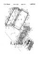
- FIG. 1is an exploded perspective view of closure apparatus embodying the present invention and illustrating the frame, splice tray stacker, and outer cover of the present invention;
- FIG. 2is a front elevational view, partially in dashed outline, illustrating the entry and exit of optical fiber cables into and out of the frame of the present invention and also illustrating the routing of optical fibers on the frame;
- FIG. 3is a transverse diagrammatical illustration of a typical optical fiber cable
- FIG. 4is a partial view, partially in dashed outline, illustrating the mounting of an optical fiber cable and a central strength member to the frame of the present invention
- FIG. 5is a partial view, partially in dashed outline, illustrating the frame of the present invention to a support strand or metal cable;
- FIG. 6is a partial bottom view of the base and wall of the splice tray stacker of the present invention.
- FIGS. 7 and 8are perspective views illustrating the manner in which dividers may be mounted to the base of the splice tray stacker of the present invention
- FIG. 9is a partial view,, in perspective, of portions of the bottom of the fold-down tray and base of the splice tray stacker of the present invention illustrating the manner in which the fold-down movement of the table is limited with respect to the base;
- FIG. 10is a perspective view illustrating the manner in which the dividers of the present invention may be mounted to the base of the tray stacker of the present invention to provide different spaces between the dividers to accommodate the stacking of optical fiber splice trays of different thicknesses;
- FIG. 10Ais an enlarged partial view of a mounting projection provided on the bottom of the dividers of the present invention.
- FIG. 11is a diagrammatical plan view illustrating the mounting of the dividers to the base of the splice tray stacker to provide different distances between the dividers;
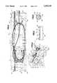
- FIG. 12is an exploded view, in perspective, of a pair of grommets of the present invention.
- FIG. 13is a diagrammatical plan view illustrating in detail the tapered passageway provided by the grommets for sealingly engaging optical fiber cables;
- FIG. 14is a cross-sectional view taken substantially along the line A--A in FIG. 12 in the direction of the arrows;
- FIG. 15is a cross-sectional view taken substantially along the line B--B in FIG. 12 in the, direction of the arrows;
- FIGS. 16 and 17are exploded views illustrating the manner in which the grommets of the present invention sealingly engage an optical fiber cable and further illustrating the manner in which the grommets in sealing engagement with a fiber optic cable are mounted in the entry/exit ports of the present invention.
- FIG. 18is a perspective view, partially in dashed outline, illustrating the manner in which the grommet doors or pressure, members provide pressure or force to the grommets to further insert or force the grommets into the entry/exit ports of the present invention and to force the grommets into further sealing engagement with an optical fiber cable.
- apparatus for containing splices between optical fibers contained in optical fiber cableswhich apparatus is indicated by general numerical designation 10.
- Apparatus 10is particularly useful as an aerial enclosure for containing splices between optical fibers and provides a flexible fiber splicing system for fiber trunk, feeder or distribution optical fiber cables.
- the apparatus of the present inventionis usable in either a butt or in-line configuration splices between optical fibers.
- the apparatus 10 of the present inventionincludes three main or primary components: a frame indicated by general numerical designation 12, a splice tray stacker indicated general numerical designation 14 and an outer cover indicated by general numerical designation 16.
- the frame 12provides a plurality of entry/exit ports for the entry and exiting of optical fiber cables as may be better understood by reference to FIG. 2 showing the entry/exit of optical fiber cables 25, 26 and 27.
- the splice tray stacker 14is for storing a plurality of optical fiber splice trays; the slice tray stacker 14, in the preferred embodiment, is mounted removably to the frame 12.
- a representative or typical optical fiber cableis illustrated in transverse cross-section in FIG. 3 and indicated by general numerical designation 30.
- Cable 30typically includes an outer protective sheath 31 surrounding a plurality of typically circularly arranged buffer tubes 33, each containing a plurality of individual optical fibers, and a central strength member 35 typically made of fiberglass.
- the frame 12referring again to FIG. 1, is provided with a plurality of mounting members 38, 39 and 40 and 41, 42 and 43 for mounting the cables to the frame 12 and a second plurality of mounting members 46, 47 and 48 and 49, 50 and 51 for mounting the central strength members of the cables to the frame 12. This may be better understood by reference to FIG.
- the mounting member 41may be a suitable hose clamp including a threaded fastener 45 for being threaded into a threaded insert (not shown) mounted in the frame 12.
- the mounting member 49may be a suitable clamp configured as shown in FIG. 4 and in FIG. 1 and which includes a threaded fastener 51 for being threaded into a threaded insert (not shown) mounted in the frame 12.
- the frame 12 of the apparatus 10 of the present inventionis provided with a pair of suitable strand mounting members indicated by general numerical designations 54 and 55, FIG. 1.
- These strand mounting membersmay be suitably mounted to the frame 12 by suitable threaded fasteners 56 and may include expandable and contractible strand clamping members 57 and 58 including threaded fasteners 59 for being threaded into threaded inserts (not shown) provided on the members 54 and 55 to clamp the members 57 and 58 to a metal cable or strand extending between poles.
- a detailed illustration of the mounting of the frame 12 to a metal cable or strand, such as strand 60,is shown in FIG. 5 with regard to strand mounting member 55.
- the splice tray stacker 14, FIG. 1is generally L-shaped in side view and includes a base 62 and a wall 64 extending upwardly from the base at substantially 90° with respect thereto.
- the base 62 and wall 64may be formed integrally, or separately, and suitably secured together such as by threaded fasteners 65 as indicated in FIG. 6.
- the base 62 and wall 64cooperatively provide openings 67 and 68 for receiving projections 71 and 72, referring now to FIG. 1, extending upwardly from the stacker mounting members 73 and 74 extending outwardly from the frame 12.
- a plurality of dividers 76are mounted removably to the base 62 and extend upwardly therefrom to provide spaces therebetween, as shown in FIG.
- optical fiber splice-traysare well known to the art, are sometimes referred to as splice tray organizers and the like, and are used to organize and store splices between individual optical fibers and to store an excess or surplus of optical fibers for use in future splicing.
- the splice tray stacker 14 and dividers 76organize the splice trays 78 and present them for ready access by splicing personnel.
- straps 81 and 82may be provided with a suitable pair of straps 81 and 82, secured to the base 62, and which straps include, for example, Velcro® patches to be placed in opposition and engagement to fasten the plurality of optical splice trays 78 to the splice tray stacker 14 as is illustrated in FIG. 8.
- the splice tray stacker 14, FIGS. 1, 7 and 8,may be provided, in the preferred embodiment, with a fold-down splicing table 86 mounted hingedly to the base 622 by suitable hinges 88 and 89 as may be best seen in FIG. 1.
- the fold-down splicing table 86is for receiving and supporting an optical fiber splice tray 78 while splices are being made to the optical fibers contained therein by splicing personnel.
- the fold-down table 86may be provided, at its corners, with a plurality of upwardly extending flexible members 91 for engaging an optical fiber splice tray 78 in a snap fit.
- the splice tray 86, with a splice tray 78 snap-fitted thereto,enables hands-free splicing by splicing personnel which is particularly advantageous when such splices are made aerially.
- the fold-down table 86may be provided with two pairs of stop members for engaging portions of the hinges 88 and 89 (FIG. 1) to limit the downward folding of the tray 86 with respect to the base 62 as illustrated by the curved arrows in FIG. 9; pair of stop, members 94 and 95 and hinge 88 are shown in FIG. 9.
- splices between individual optical fiberscan be made in either single or mass fusion configurations.
- single fusion splicesare smaller in diameter or thickness than mass fusion splices, and as is still further known in the art, optical fiber splice trays, such as trays 76, are provided in different thicknesses, a narrower thickness for accommodating single fusion splices and a greater thicknesses for accommodating mass fusion splices.
- the splice tray stacker base 62 and dividers 76 of the present inventionare provided with cooperating means for varying the spacing between the dividers to accommodate optical fiber splice trays of different thicknesses. As may be understood from FIGS.
- the splice tray stacker base 62is provided with a plurality of laterally spaced rows of holes, such as row of holes 101 and 102 and row of holes 104 and 105 shown in FIG. 11. It will be noted from FIG. 11 that row of holes 101 and 102 and row of holes 104 and 105 are displaced laterally with respect to each other, i.e., the row of holes 101 and 102 is displaced leftwardly in FIG. 11 with respect to the row of holes 104 and 105, or conversely the row of holes 104 and 105 is displaced rightwardly with respect to the row of holes 101 and 102.
- FIG. 10is provided along their bottom edge with a pair of downwardly extending flexible projections 108 and 109 (projection 109 is shown in greater detail in FIG. 10A) for being wedgedly received in the holes formed in a row of such holes to mount the dividers removably to the splice trays tacker base 62.
- projection 109is shown in greater detail in FIG. 10A
- the divider 76Ais spaced a first distance D1 from the adjacent divider 76B to accommodate and stack thinner optical fiber splice trays containing the thinner single fusion splices.
- FIG. 10Aupon the divider 76A, FIG.
- the divider 76Ais now spaced a second distance D1, greater than distance D2, from the adjacent divider 76 to provide a larger space for accommodating and stacking thicker optical fiber splice trays containing the thicker fusion splices. Accordingly, it will be understood in accordance with the teaching of the present invention that a single set of dividers and a single splice tray stacker may be used to accommodate and store optical fiber splice trays of different thicknesses.
- the splice tray stacker 14, FIG. 1is mounted removably to the frame 12, as indicated by the broken lines 107 and 108 by inserting the projections 71 and 72 on the stacker mounting members 73 and 74 into the openings 67 and 68, FIG. 6, provided on the stacker 14 and by threading the threaded fasteners 110 and 111, provided on the stacker 14, into threaded inserts provided on the stacker mounting members 112 and 114 extending outwardly from the frame 12.
- the threaded insertsdue to the smallness of size, are not shown in FIG. 1, but it will be understood that such threaded inserts are mounted in the circular openings shown in the outer portions of the mounting members 112 and 114.
- the threaded fastening of the fasteners 110 and 111is also indicated diagrammatically in FIG. 1 by the dashed lines 116 and 117.
- the entry/exit ports 18, 19 and 20 and 21, 22 and 23, FIG. 1,are provided with grommets which engage the optical fiber cables, entering and exiting these ports and provide a substantially air-tight seal around the cables.
- a pair of grommetsare mounted in each port, for example, a pair of grommets 120 and 121 are mounted in port 20 and these grommets, representative of the other grommets, are shown separated,, enlarged, and in greater detail in FIG. 12 where they are indicated by general numerical designations. It will be generally understood, and referring to the diagrammatical illustration of FIG.
- the representative grommets 120 and 121cooperatively provide an internal passageway indicated by general numerical designation 122 including or defined by two axially aligned, truncated, conical passageway sections 124 and 125 tapering or narrowing inwardly as illustrated in FIG. 13. These truncated conical passageway sections 124 and 125 are shown in dashed outline in FIG. 12.
- the representative pair of grommets 120 and 121, FIG. 12,are each generally U-shaped and include a generally semi-circular portion 127 extending into two generally parallel straight portions 128 and 129. It will be noted from FIG. 12 that the truncated conical passageway sections or portions 124 and 125 extend through the generally semi-circular portions 127.
- the representative grommet 120is provided with a thin wall 131 transverse to and normally occluding the passageway section 124 and normally preventing the passage of air therethrough.
- the generally straight portions 128 and 129 of the grommets 120 and 121have a longitudinally extending space 133 therebetween and from the cross-sectional view shown in FIG. 15 of grommet 120, it will be noted that a thin wall 134 extends longitudinally between the generally straight portions 128 and 129 normally occluding the space 133 to normally prevent the passage of air through the space 133.
- grommets 120 and 121are made of a suitable flexible material, such as for example a suitable and commercially available thermoplastic elastomeric material. It will be understood that the thin walls 131 and 134, FIGS. 14 and 15, normally close and seal the entry/exit ports 18, 19 and 20 and 21, 22 and 23, FIG. 1, when no optical fiber cable is entering or exiting such ports.
- the grommets 120 and 121are sufficiently flexible, and the walls 131 and 134, FIGS. 14 and 15 sufficiently thin, that the application of manual force, provided by the hands and/or fingers of optical fiber splicing personnel, can spread the generally straight portions 128 and 129 apart, as shown in FIG.
- the grommets 120 and 121 and the entry/exit port 20, representative of all grommets and ports,are provided with cooperating ribs and grooves for mounting the grommets in the ports with the grooves receiving the ribs; note ribs 141 and 142 and groove 143 provided on grommet 120, FIG. 12, and rib 144 and groove 145 at entry/exit port 20. It will be understood, for example, that upon the optical fiber cable 136, FIG. 17, being received within the tapered passageway 122, FIG.
- the straight portions of the grommets 120 and 121will be slightly spread apart and upon the manual forced entry of the grommets and optical fiber cable 136 into the entry/exit port 20 the straight portions of the grommets will be forced towards each other to further force the grommets into sealing engagement with the optical fiber 136.
- the grommets of the present inventione.g. grommets 120 and 121, are self-sizing in that the tapered passageway 122, FIG.
- the frame 12note FIGS. 1 and 18, is provided with a pair of grommet doors or pressure applying members 147 and 148 mounted hingedly to the frame 12.
- the grommet doors 147 and 148are provided with suitable threaded fasteners extending therethrough which are received within threaded inserts (not shown) provided in the frame 12, to force the grommet doors into engagement with the grommets and to further force and seat the grommets into the entry/exits ports and further force the grommets into sealing engagement with the optical fiber cables.
- the downward pivoting of the hinged grommet door or pressure member 148is indicated by the curved arrow 149 in FIG. 18.
- the generally straight portions 128 and 129, FIG. 12, of the grommetsare provided with an outward taper as are the ribs 141 and 142 and groove 143.
- the groove 144 and rib 145 provided at the entry/exit port 20are provided with an outward taper whereby upon the insertion of the grommets surrounding an optical fiber cable such insertion and seating in the entry/exit port further compresses the straight portions of the grommets towards each other and forces the grommet, particularly the conical surfaces providing the tapered passageway 122, FIG. 13, into still further sealing engagement with the optical fiber cable.
- the coveris of generally clam shell type or configuration and includes a pair of hinged cover members indicated by general numerical designations 151 and 152.
- the cover members 151 and 152include, respectively, bases 153 and 154 which are, respectively, circumscribed by outwardly extending walls 156 and 157.
- the generally opposed cover edges 158 and 159are provided with cooperative hinge forming members providing the hinges 161 and 162, 163 and 164.
- the edge 166 of the cover member 154is provided with a plurality of latch members 169, 170, 171 and 172 of the type known to the art, for engaging and latching to outwardly extending ridge portions 174, 175, 176 and 177 provided on the wall 156 of cover member 151 to latch and fasten the cover members 151 and 152 closed and fastened around the frame 12 with stacker 14 mounted removably thereto as described above.
- the outer cover 151provides mechanical and environmental protection to the frame 12 and stacker 14 and, of course, optical fibers and optical fiber splices contained therein. As may be further understood from FIG.
- the end walls 178 and 179 of the cover member 151are provided with a plurality of indentations for receiving optical fiber cables entering and exiting the frame 12 upon the cover 16 being fastened around the frame and tray stacker 14.
- the cover members 151 and 152may be provided, respectively, with screen filled openings 181 and 182 to permit the relatively free flow of air in and out of the cover 16 upon being fastened around the frame 12 and tray stacker 14 so that the temperature and humidity of the air inside and outside the cover are substantially the same. This substantially eliminates the formation of condensation in the cover 16 upon being closed and fastened around the frame and tray stacker. It will be understood that the mesh of the screen is sufficiently large to permit the free flow of air therethrough as described and sufficiently small to prevent the entry of unwanted debris and the like.
- the wire of the meshis sufficiently strong to substantially prevent the entry of rodents into the cover and to prevent the wire from being ruptured by rodents.
- the apparatus 10 of the present inventionmay be said to be a free-breathing closure or an aerial breathable fiber enclosure.
- the end walls 178 and 179 of the cover member 151are respectively provided with indentations 186 and 188 to accommodate or permit the passage therethrough of the shafts 190 and 191 of the strand clamps 54 and 55.
- the frame 12may be mounted removably to the base 153 of the cover portion 151.
- the base 153 of the cover portion 151is provided with a pair of threaded inserts 192 and 194 for threadedly receiving a pair of threaded fasteners provided on the frame 12 in corresponding positions.
- Threaded fastener 184, FIG. 1extends rotatably through the frame 12 and is for threaded engagement with the threaded insert 182; the other threaded fastener provided on the frame 12 is not shown in FIG. 1 because it is obscured by the rightward portion of the frame including the grommets, but such other threaded fastener is threadedly received in the threaded insert 181.
- the frame 12may be provided with a plurality of optical fiber routing rings 195, 196, 197 and 198 for routing the optical fibers around the frame 12 as illustrated particularly in FIG. 2.
- the frame 12, splice tray stacker 14, dividers 76, fold-down table 86 and cover 16may be made of a suitable plastic, such as for example commercially available ABS/PVC and may be suitably injection molded.
- the strand mounting members 54 and 55may be made of a suitable stainless steel, and the various threaded fasteners may be suitable threaded fasteners or preferably 1/4 turn fasteners.
Landscapes
- Physics & Mathematics (AREA)
- General Physics & Mathematics (AREA)
- Optics & Photonics (AREA)
- Light Guides In General And Applications Therefor (AREA)
Abstract
Description
Claims (27)
Priority Applications (1)
| Application Number | Priority Date | Filing Date | Title |
|---|---|---|---|
| US08/198,562US5495549A (en) | 1994-02-18 | 1994-02-18 | Optical fiber splice closure |
Applications Claiming Priority (1)
| Application Number | Priority Date | Filing Date | Title |
|---|---|---|---|
| US08/198,562US5495549A (en) | 1994-02-18 | 1994-02-18 | Optical fiber splice closure |
Publications (1)
| Publication Number | Publication Date |
|---|---|
| US5495549Atrue US5495549A (en) | 1996-02-27 |
Family
ID=22733907
Family Applications (1)
| Application Number | Title | Priority Date | Filing Date |
|---|---|---|---|
| US08/198,562Expired - LifetimeUS5495549A (en) | 1994-02-18 | 1994-02-18 | Optical fiber splice closure |
Country Status (1)
| Country | Link |
|---|---|
| US (1) | US5495549A (en) |
Cited By (89)
| Publication number | Priority date | Publication date | Assignee | Title |
|---|---|---|---|---|
| EP0797114A3 (en)* | 1996-03-20 | 1998-01-07 | RXS Kabelgarnituren Gesellschaft mit beschränkter Haftung | Cable sleeve |
| USD390235S (en) | 1996-04-30 | 1998-02-03 | Next Level Communications | Communication equipment enclosure |
| USD390571S (en) | 1997-04-10 | 1998-02-10 | Communications Technology Corporation | Terminal block enclosure |
| US5726392A (en)* | 1997-02-21 | 1998-03-10 | Communications Technology Corporation | Communications housing having grommet assembly |
| US5754724A (en)* | 1996-11-08 | 1998-05-19 | Antec Corporation | Fiber optic support apparatus |
| US5754723A (en)* | 1993-07-08 | 1998-05-19 | Raychem Gmbh | Multi-filament splice enclosures |
| US5793921A (en)* | 1995-03-20 | 1998-08-11 | Psi Telecommunications, Inc. | Kit and method for converting a conductive cable closure to a fiber optic cable closure |
| US5815629A (en)* | 1995-08-18 | 1998-09-29 | Siemens Aktiengesellschaft | Cap sleeve for light waveguide cables |
| US5835657A (en)* | 1995-12-08 | 1998-11-10 | Psi Telecommunications, Inc. | Fiber optic splice tray |
| US5835658A (en)* | 1995-03-20 | 1998-11-10 | Psi Telecommunications, Inc. | Method and apparatus for anchoring an optical fiber cable |
| USD418515S (en)* | 1997-05-30 | 2000-01-04 | Next Level Communications | Communication equipment enclosure |
| GB2343013A (en)* | 1998-10-22 | 2000-04-26 | Bowthorpe Plc | Optical fibre storage tray with fibre retaining member |
| WO2001003264A3 (en)* | 1999-07-01 | 2001-03-15 | Tyco Electronics Raychem Nv | Cable container having improved fastening means |
| US6292614B1 (en) | 1999-08-24 | 2001-09-18 | Siecor Operations, Llc | Movable bracket for holding internal components of an optical fiber interconnection closure during servicing and associated method |
| US6382845B1 (en) | 1999-03-02 | 2002-05-07 | Ameritech Corporation | Fiber optic patch kit and method for using same |
| US20020150371A1 (en)* | 2001-04-12 | 2002-10-17 | Battey Jennifer A. | Fiber management frame for securely retaining optical fiber connection trays |
| US6496640B1 (en) | 1999-12-16 | 2002-12-17 | Corning Cable Systems Llc | Splice closure with removable and pivotable splice trays, and associated methods |
| WO2003019243A3 (en)* | 2001-05-21 | 2003-07-24 | Wave7 Optics Inc | Cable splice enclosure and components |
| US6646200B1 (en) | 2002-07-29 | 2003-11-11 | Bellsouth Intellectual Property Corporation | Apparatus, systems, and methods for adjusting the position of a hanging aerial terminal |
| US20040001686A1 (en)* | 2002-06-28 | 2004-01-01 | Smith Kelly J. | Aerial closure for local convergence point |
| GB2391953A (en)* | 2002-08-16 | 2004-02-18 | Spirent Plc | Storage tray with optic fibre grooved resilient retainer |
| US20050125837A1 (en)* | 2001-07-05 | 2005-06-09 | Wave7 Optics, Inc. | Method and system for providing a return path for signals generated by legacy video service terminals in an optical network |
| US20050175307A1 (en)* | 2004-02-06 | 2005-08-11 | Battey Jennifer A. | Optical connection closure having at least one connector port |
| US20060020975A1 (en)* | 2001-07-05 | 2006-01-26 | Wave7 Optics, Inc. | System and method for propagating satellite TV-band, cable TV-band, and data signals over an optical network |
| US20060039699A1 (en)* | 2004-08-10 | 2006-02-23 | Wave7 Optics, Inc. | Countermeasures for idle pattern SRS interference in ethernet optical network systems |
| US20060075428A1 (en)* | 2004-10-04 | 2006-04-06 | Wave7 Optics, Inc. | Minimizing channel change time for IP video |
| US7038910B1 (en) | 2002-01-07 | 2006-05-02 | Wave7 Optics, Inc. | System and method for removing heat from a subscriber optical interface |
| US20060187863A1 (en)* | 2004-12-21 | 2006-08-24 | Wave7 Optics, Inc. | System and method for operating a wideband return channel in a bi-directional optical communication system |
| US20060233509A1 (en)* | 2005-04-14 | 2006-10-19 | Craig Ray | Optical fiber repair apparatus with adjustable guide member and methods for using the same |
| US20060251373A1 (en)* | 2002-10-15 | 2006-11-09 | Wave7 Optics, Inc. | Reflection suppression for an optical fiber |
| US20060269285A1 (en)* | 2002-01-08 | 2006-11-30 | Wave7 Optics, Inc. | Optical network system and method for supporting upstream signals propagated according to a cable modem protocol |
| US20070047959A1 (en)* | 2005-08-12 | 2007-03-01 | Wave7 Optics, Inc. | System and method for supporting communications between subcriber optical interfaces coupled to the same laser transceiver node in an optical network |
| US20070077069A1 (en)* | 2000-10-04 | 2007-04-05 | Farmer James O | System and method for communicating optical signals upstream and downstream between a data service provider and subscribers |
| US20070223928A1 (en)* | 2001-08-03 | 2007-09-27 | Farmer James O | Method and system for providing a return path for signals generated by legacy terminals in an optical network |
| US20070292133A1 (en)* | 2002-05-20 | 2007-12-20 | Whittlesey Paul F | System and method for communicating optical signals to multiple subscribers having various bandwidth demands connected to the same optical waveguide |
| US20080085117A1 (en)* | 2004-08-19 | 2008-04-10 | Farmer James O | System and method for communicating optical signals between a data service provider and subscribers |
| WO2008118407A1 (en)* | 2007-03-28 | 2008-10-02 | Lioyo, Herbert, King | Direct bury splice kit |
| US20080253730A1 (en)* | 2007-04-10 | 2008-10-16 | Terry Dean Cox | Grommet and plate assembly for sealing fiber optic closures |
| US7454141B2 (en) | 2003-03-14 | 2008-11-18 | Enablence Usa Fttx Networks Inc. | Method and system for providing a return path for signals generated by legacy terminals in an optical network |
| US20080292249A1 (en)* | 2007-05-24 | 2008-11-27 | Yasushi Kimura | Electronic equipment |
| FR2917186A1 (en)* | 2007-06-11 | 2008-12-12 | Free Soc Par Actions Simplifie | RECORDING HOUSING FOR OPTICAL FIBERS |
| US7529485B2 (en) | 2001-07-05 | 2009-05-05 | Enablence Usa Fttx Networks, Inc. | Method and system for supporting multiple services with a subscriber optical interface located outside a subscriber's premises |
| US20090202214A1 (en)* | 2007-12-11 | 2009-08-13 | Adc Telecommuniactions, Inc. | Wall box adapted to be mounted at a mid-span access location of a telecommunications cable |
| US20090238531A1 (en)* | 2008-01-09 | 2009-09-24 | Adc Telecommunications, Inc. | Wall box adapted to be mounted at a mid-span access location of a telecommunications cable |
| US20090252472A1 (en)* | 2008-02-15 | 2009-10-08 | Adc Telecommunications, Inc. | Fiber Optic Splice Enclosure |
| US20090257728A1 (en)* | 2008-04-10 | 2009-10-15 | Mures Marcel G | Terminal shields for protecting optical components in optical assemblies |
| US7616901B2 (en) | 2005-08-10 | 2009-11-10 | Enablence Usa Fttx Networks Inc. | Countermeasures for idle pattern SRS interference in ethernet optical network systems |
| EP2163926A1 (en)* | 2008-09-09 | 2010-03-17 | B.V. Kunststoffenindustrie Attema | A holding system provided with a cassette comprising a holder for holding optical fibre connections |
| US20100189404A1 (en)* | 2009-01-28 | 2010-07-29 | Adc Telecommunications, Inc. | Fiber optic enclosure |
| USRE41777E1 (en) | 1998-07-27 | 2010-09-28 | Adc Telecommunications, Inc. | Outside plant fiber distribution apparatus and method |
| US20100314266A1 (en)* | 2009-06-12 | 2010-12-16 | Adc Gmbh | Housing for accommodating at least one gas stopper |
| US20110013875A1 (en)* | 2009-07-16 | 2011-01-20 | Adc Telecommunications, Inc. | Fiber optic enclosure with adapter bulkhead positioned beneath pivotal splice tray |
| WO2011011509A1 (en)* | 2009-07-21 | 2011-01-27 | Afl Telecommunications Llc | Modular resealable high conductor count packaging and method |
| US20110268405A1 (en)* | 2010-04-30 | 2011-11-03 | Cote Monique L | Stackable shelves for a fiber optic housing, and related components and methods |
| US20130056599A1 (en)* | 2011-09-02 | 2013-03-07 | Steven Ray Baker | Apparatus and method for toollessly, releasably attaching components to a structure |
| US8755663B2 (en) | 2010-10-28 | 2014-06-17 | Corning Cable Systems Llc | Impact resistant fiber optic enclosures and related methods |
| US8873926B2 (en) | 2012-04-26 | 2014-10-28 | Corning Cable Systems Llc | Fiber optic enclosures employing clamping assemblies for strain relief of cables, and related assemblies and methods |
| US8989547B2 (en) | 2011-06-30 | 2015-03-24 | Corning Cable Systems Llc | Fiber optic equipment assemblies employing non-U-width-sized housings and related methods |
| US8985862B2 (en) | 2013-02-28 | 2015-03-24 | Corning Cable Systems Llc | High-density multi-fiber adapter housings |
| US8992099B2 (en) | 2010-02-04 | 2015-03-31 | Corning Cable Systems Llc | Optical interface cards, assemblies, and related methods, suited for installation and use in antenna system equipment |
| US9008485B2 (en) | 2011-05-09 | 2015-04-14 | Corning Cable Systems Llc | Attachment mechanisms employed to attach a rear housing section to a fiber optic housing, and related assemblies and methods |
| US9020320B2 (en) | 2008-08-29 | 2015-04-28 | Corning Cable Systems Llc | High density and bandwidth fiber optic apparatuses and related equipment and methods |
| US9022814B2 (en) | 2010-04-16 | 2015-05-05 | Ccs Technology, Inc. | Sealing and strain relief device for data cables |
| US9038832B2 (en) | 2011-11-30 | 2015-05-26 | Corning Cable Systems Llc | Adapter panel support assembly |
| US9042702B2 (en) | 2012-09-18 | 2015-05-26 | Corning Cable Systems Llc | Platforms and systems for fiber optic cable attachment |
| US9069151B2 (en) | 2011-10-26 | 2015-06-30 | Corning Cable Systems Llc | Composite cable breakout assembly |
| US9075217B2 (en) | 2010-04-30 | 2015-07-07 | Corning Cable Systems Llc | Apparatuses and related components and methods for expanding capacity of fiber optic housings |
| US9116324B2 (en) | 2010-10-29 | 2015-08-25 | Corning Cable Systems Llc | Stacked fiber optic modules and fiber optic equipment configured to support stacked fiber optic modules |
| US9213161B2 (en) | 2010-11-05 | 2015-12-15 | Corning Cable Systems Llc | Fiber body holder and strain relief device |
| US9519118B2 (en) | 2010-04-30 | 2016-12-13 | Corning Optical Communications LLC | Removable fiber management sections for fiber optic housings, and related components and methods |
| US9645317B2 (en) | 2011-02-02 | 2017-05-09 | Corning Optical Communications LLC | Optical backplane extension modules, and related assemblies suitable for establishing optical connections to information processing modules disposed in equipment racks |
| US9977211B1 (en) | 2017-04-21 | 2018-05-22 | Afl Telecommunications Llc | Optical connection terminals for fiber optic communications networks |
| US20180203200A1 (en)* | 2011-02-16 | 2018-07-19 | Commscope Technologies Llc | Fiber optic closure |
| US10094996B2 (en) | 2008-08-29 | 2018-10-09 | Corning Optical Communications, Llc | Independently translatable modules and fiber optic equipment trays in fiber optic equipment |
| USD839210S1 (en)* | 2015-11-13 | 2019-01-29 | Corning Optical Communications LLC | Fiber optic cassette with surface ornamentation |
| US10281670B2 (en) | 2015-01-12 | 2019-05-07 | Afl Telecommunications Llc | Fiber optic terminal enclosure |
| US10520692B2 (en) | 2015-11-11 | 2019-12-31 | Afl Telecommunications Llc | Optical connection terminals for fiber optic communications networks |
| US11194111B2 (en)* | 2017-06-15 | 2021-12-07 | Commscope Technologies Llc | Fiber optic splice closure and assemblies |
| FR3113955A1 (en)* | 2020-09-07 | 2022-03-11 | Guillaume Chamerois | Aerial sleeve for optical fiber |
| US11294135B2 (en) | 2008-08-29 | 2022-04-05 | Corning Optical Communications LLC | High density and bandwidth fiber optic apparatuses and related equipment and methods |
| EP3785058A4 (en)* | 2018-04-23 | 2022-05-18 | CommScope Technologies LLC | Mounting bracket system for telecommunications equipment |
| WO2022177994A1 (en) | 2021-02-16 | 2022-08-25 | Preformed Line Products Co. | Terminal closure |
| CN115524815A (en)* | 2022-09-28 | 2022-12-27 | 惠州市飞博康实业有限公司 | An optical fiber splicing box |
| USD1008196S1 (en)* | 2021-06-03 | 2023-12-19 | Geddy's Mom Lp | Cable securing apparatus |
| USD1056854S1 (en)* | 2022-09-20 | 2025-01-07 | Eaton Intelligent Power Limited | Charging box |
| US12222573B2 (en) | 2020-08-07 | 2025-02-11 | Commscope Technologies Llc | Adjustable cable management system |
| US12235503B2 (en) | 2019-11-07 | 2025-02-25 | Commscope Technologies Llc | Telecommunications enclosure mounting system |
| USD1069729S1 (en)* | 2022-09-12 | 2025-04-08 | Magen Eco Energy A.c.s Ltd. | Junction box for pipework |
| USD1083866S1 (en)* | 2022-08-11 | 2025-07-15 | Yaoz Solutions Ltd. | Fiber optic splice closure |
Citations (13)
| Publication number | Priority date | Publication date | Assignee | Title |
|---|---|---|---|---|
| US4595255A (en)* | 1983-08-24 | 1986-06-17 | Fiberlan, Inc. | Optical fiber wiring center |
| US4793682A (en)* | 1988-01-11 | 1988-12-27 | Gte Products Corporation | Fiber optic splice and fiber holder and housing therefor |
| US4927227A (en)* | 1988-10-31 | 1990-05-22 | At&T Bell Laboratories | Optical fiber cable closure |
| US4958903A (en)* | 1988-12-09 | 1990-09-25 | At&T Bell Laboratories | Splice closure |
| US5042901A (en)* | 1990-07-31 | 1991-08-27 | Siecor Corporation | Preconnectorized optical splice closure |
| US5131066A (en)* | 1988-11-26 | 1992-07-14 | Bowthorpe-Hellerman Limited | Optical fibre splice tray arrangement |
| US5249253A (en)* | 1984-04-11 | 1993-09-28 | Nv Raychem Sa | Electrofit fibre optics butt splice |
| US5249252A (en)* | 1992-08-31 | 1993-09-28 | Alcatel Network Systems, Inc. | Optical fiber splice tray with cable tray hinge |
| US5255337A (en)* | 1989-01-17 | 1993-10-19 | N.V. Raychem S.A. | Splice case for optical fibre cable |
| US5261024A (en)* | 1989-11-21 | 1993-11-09 | Raynet Corporation | Card cage used for coupling to telecommunications media |
| US5278933A (en)* | 1992-06-30 | 1994-01-11 | Hunsinger Terrance D | Fiber optic splice organizer and associated method |
| US5313546A (en)* | 1991-11-29 | 1994-05-17 | Sirti, S.P.A. | Hermetically sealed joint cover for fibre optic cables |
| US5402515A (en)* | 1994-03-01 | 1995-03-28 | Minnesota Mining And Manufacturing Company | Fiber distribution frame system, cabinets, trays and fiber optic connector couplings |
- 1994
- 1994-02-18USUS08/198,562patent/US5495549A/ennot_activeExpired - Lifetime
Patent Citations (13)
| Publication number | Priority date | Publication date | Assignee | Title |
|---|---|---|---|---|
| US4595255A (en)* | 1983-08-24 | 1986-06-17 | Fiberlan, Inc. | Optical fiber wiring center |
| US5249253A (en)* | 1984-04-11 | 1993-09-28 | Nv Raychem Sa | Electrofit fibre optics butt splice |
| US4793682A (en)* | 1988-01-11 | 1988-12-27 | Gte Products Corporation | Fiber optic splice and fiber holder and housing therefor |
| US4927227A (en)* | 1988-10-31 | 1990-05-22 | At&T Bell Laboratories | Optical fiber cable closure |
| US5131066A (en)* | 1988-11-26 | 1992-07-14 | Bowthorpe-Hellerman Limited | Optical fibre splice tray arrangement |
| US4958903A (en)* | 1988-12-09 | 1990-09-25 | At&T Bell Laboratories | Splice closure |
| US5255337A (en)* | 1989-01-17 | 1993-10-19 | N.V. Raychem S.A. | Splice case for optical fibre cable |
| US5261024A (en)* | 1989-11-21 | 1993-11-09 | Raynet Corporation | Card cage used for coupling to telecommunications media |
| US5042901A (en)* | 1990-07-31 | 1991-08-27 | Siecor Corporation | Preconnectorized optical splice closure |
| US5313546A (en)* | 1991-11-29 | 1994-05-17 | Sirti, S.P.A. | Hermetically sealed joint cover for fibre optic cables |
| US5278933A (en)* | 1992-06-30 | 1994-01-11 | Hunsinger Terrance D | Fiber optic splice organizer and associated method |
| US5249252A (en)* | 1992-08-31 | 1993-09-28 | Alcatel Network Systems, Inc. | Optical fiber splice tray with cable tray hinge |
| US5402515A (en)* | 1994-03-01 | 1995-03-28 | Minnesota Mining And Manufacturing Company | Fiber distribution frame system, cabinets, trays and fiber optic connector couplings |
Non-Patent Citations (2)
| Title |
|---|
| Raychem advertisement Bulletin "TRAC Aerial Closure" 2 pages (No date). |
| Raychem advertisement Bulletin TRAC Aerial Closure 2 pages (No date).* |
Cited By (175)
| Publication number | Priority date | Publication date | Assignee | Title |
|---|---|---|---|---|
| US5754723A (en)* | 1993-07-08 | 1998-05-19 | Raychem Gmbh | Multi-filament splice enclosures |
| US5835658A (en)* | 1995-03-20 | 1998-11-10 | Psi Telecommunications, Inc. | Method and apparatus for anchoring an optical fiber cable |
| US5793921A (en)* | 1995-03-20 | 1998-08-11 | Psi Telecommunications, Inc. | Kit and method for converting a conductive cable closure to a fiber optic cable closure |
| US5793920A (en)* | 1995-03-20 | 1998-08-11 | Psi Telecommunications, Inc. | Method and apparatus for anchoring an optical fiber cable |
| US5825961A (en)* | 1995-03-20 | 1998-10-20 | Psi Telecommunications, Inc. | Fiber optic closure with cable adapter spool |
| US5815629A (en)* | 1995-08-18 | 1998-09-29 | Siemens Aktiengesellschaft | Cap sleeve for light waveguide cables |
| US5835657A (en)* | 1995-12-08 | 1998-11-10 | Psi Telecommunications, Inc. | Fiber optic splice tray |
| CN1068980C (en)* | 1996-03-20 | 2001-07-25 | Rxs电缆装备有限公司 | Cable junction box |
| EP0797114A3 (en)* | 1996-03-20 | 1998-01-07 | RXS Kabelgarnituren Gesellschaft mit beschränkter Haftung | Cable sleeve |
| USD390235S (en) | 1996-04-30 | 1998-02-03 | Next Level Communications | Communication equipment enclosure |
| US5754724A (en)* | 1996-11-08 | 1998-05-19 | Antec Corporation | Fiber optic support apparatus |
| US5726392A (en)* | 1997-02-21 | 1998-03-10 | Communications Technology Corporation | Communications housing having grommet assembly |
| USD390571S (en) | 1997-04-10 | 1998-02-10 | Communications Technology Corporation | Terminal block enclosure |
| USD418515S (en)* | 1997-05-30 | 2000-01-04 | Next Level Communications | Communication equipment enclosure |
| USRE41777E1 (en) | 1998-07-27 | 2010-09-28 | Adc Telecommunications, Inc. | Outside plant fiber distribution apparatus and method |
| USRE42258E1 (en) | 1998-07-27 | 2011-03-29 | Adc Telecommunications, Inc. | Outside plant fiber distribution apparatus and method |
| GB2343013A (en)* | 1998-10-22 | 2000-04-26 | Bowthorpe Plc | Optical fibre storage tray with fibre retaining member |
| US20080292252A1 (en)* | 1999-03-02 | 2008-11-27 | Glen Edward Gould | Fiber Optic Patch Kit and Method for Using the Same |
| US20050265680A1 (en)* | 1999-03-02 | 2005-12-01 | Sbc Properties, L.P. | Fiber optic patch kit and method for using same |
| US6905263B2 (en) | 1999-03-02 | 2005-06-14 | Sbc Properties, L.P. | Fiber optic patch kit and method for using same |
| US7171101B2 (en) | 1999-03-02 | 2007-01-30 | Sbc Properties, L.P. | Fiber optic patch kit and method for using same |
| US7769267B2 (en) | 1999-03-02 | 2010-08-03 | At&T Intellectual Property I, L.P. | Fiber optic patch kit and method for using the same |
| US6382845B1 (en) | 1999-03-02 | 2002-05-07 | Ameritech Corporation | Fiber optic patch kit and method for using same |
| US20100278501A1 (en)* | 1999-03-02 | 2010-11-04 | Glen Edward Gould | Fiber Optic Patch Kit and Method For Using Same |
| US20020146220A1 (en)* | 1999-03-02 | 2002-10-10 | Ameritech Corporation | Fiber optic patch kit and method for using same |
| US7991259B2 (en)* | 1999-03-02 | 2011-08-02 | At & T Intellectual Property I, Lp | Fiber optic patch kit and method for using same |
| US7379649B2 (en) | 1999-03-02 | 2008-05-27 | At&T Knowledge Ventures, Lp | Fiber optic patch kit and method for using the same |
| US20070086722A1 (en)* | 1999-03-02 | 2007-04-19 | Gould Glen Edward | Fiber optic patch kit and method for using the same |
| WO2001003264A3 (en)* | 1999-07-01 | 2001-03-15 | Tyco Electronics Raychem Nv | Cable container having improved fastening means |
| US6292614B1 (en) | 1999-08-24 | 2001-09-18 | Siecor Operations, Llc | Movable bracket for holding internal components of an optical fiber interconnection closure during servicing and associated method |
| US6496640B1 (en) | 1999-12-16 | 2002-12-17 | Corning Cable Systems Llc | Splice closure with removable and pivotable splice trays, and associated methods |
| US20070077069A1 (en)* | 2000-10-04 | 2007-04-05 | Farmer James O | System and method for communicating optical signals upstream and downstream between a data service provider and subscribers |
| US7606492B2 (en) | 2000-10-04 | 2009-10-20 | Enablence Usa Fttx Networks Inc. | System and method for communicating optical signals upstream and downstream between a data service provider and subscribers |
| US6963689B2 (en) | 2001-04-12 | 2005-11-08 | Corning Cable Systems Llc | Fiber management frame for securely retaining optical fiber connection trays |
| US6798967B2 (en)* | 2001-04-12 | 2004-09-28 | Corning Cable Systems Llc | Fiber management frame for securely retaining optical fiber connection trays |
| US20020150371A1 (en)* | 2001-04-12 | 2002-10-17 | Battey Jennifer A. | Fiber management frame for securely retaining optical fiber connection trays |
| WO2003019243A3 (en)* | 2001-05-21 | 2003-07-24 | Wave7 Optics Inc | Cable splice enclosure and components |
| US6950593B2 (en) | 2001-05-21 | 2005-09-27 | Wave7 Optics, Inc. | Cable splice enclosure |
| US6711337B2 (en)* | 2001-05-21 | 2004-03-23 | Wave7 Optics, Inc. | Cable splice enclosure and components |
| US20040161217A1 (en)* | 2001-05-21 | 2004-08-19 | Wave7 Optics, Inc. | Cable splice enclosure |
| US7877014B2 (en) | 2001-07-05 | 2011-01-25 | Enablence Technologies Inc. | Method and system for providing a return path for signals generated by legacy video service terminals in an optical network |
| US7529485B2 (en) | 2001-07-05 | 2009-05-05 | Enablence Usa Fttx Networks, Inc. | Method and system for supporting multiple services with a subscriber optical interface located outside a subscriber's premises |
| US20060020975A1 (en)* | 2001-07-05 | 2006-01-26 | Wave7 Optics, Inc. | System and method for propagating satellite TV-band, cable TV-band, and data signals over an optical network |
| US20050125837A1 (en)* | 2001-07-05 | 2005-06-09 | Wave7 Optics, Inc. | Method and system for providing a return path for signals generated by legacy video service terminals in an optical network |
| US7593639B2 (en) | 2001-08-03 | 2009-09-22 | Enablence Usa Fttx Networks Inc. | Method and system for providing a return path for signals generated by legacy terminals in an optical network |
| US20070223928A1 (en)* | 2001-08-03 | 2007-09-27 | Farmer James O | Method and system for providing a return path for signals generated by legacy terminals in an optical network |
| US7355848B1 (en) | 2002-01-07 | 2008-04-08 | Wave7 Optics, Inc. | System and method for removing heat from a subscriber optical interface |
| US7038910B1 (en) | 2002-01-07 | 2006-05-02 | Wave7 Optics, Inc. | System and method for removing heat from a subscriber optical interface |
| US20060269285A1 (en)* | 2002-01-08 | 2006-11-30 | Wave7 Optics, Inc. | Optical network system and method for supporting upstream signals propagated according to a cable modem protocol |
| US7583897B2 (en) | 2002-01-08 | 2009-09-01 | Enablence Usa Fttx Networks Inc. | Optical network system and method for supporting upstream signals propagated according to a cable modem protocol |
| US20070292133A1 (en)* | 2002-05-20 | 2007-12-20 | Whittlesey Paul F | System and method for communicating optical signals to multiple subscribers having various bandwidth demands connected to the same optical waveguide |
| US7623786B2 (en) | 2002-05-20 | 2009-11-24 | Enablence Usa Fttx Networks, Inc. | System and method for communicating optical signals to multiple subscribers having various bandwidth demands connected to the same optical waveguide |
| US20040001686A1 (en)* | 2002-06-28 | 2004-01-01 | Smith Kelly J. | Aerial closure for local convergence point |
| US6766094B2 (en) | 2002-06-28 | 2004-07-20 | Corning Cable Systems Llc | Aerial closure for local convergence point |
| US6646200B1 (en) | 2002-07-29 | 2003-11-11 | Bellsouth Intellectual Property Corporation | Apparatus, systems, and methods for adjusting the position of a hanging aerial terminal |
| EP1389736A1 (en)* | 2002-08-16 | 2004-02-18 | Spirent Plc | Storage tray for optical fibre cable joints |
| GB2391953B (en)* | 2002-08-16 | 2005-06-08 | Spirent Plc | Enclosures of optical fibre cable joints |
| GB2391953A (en)* | 2002-08-16 | 2004-02-18 | Spirent Plc | Storage tray with optic fibre grooved resilient retainer |
| US20060251373A1 (en)* | 2002-10-15 | 2006-11-09 | Wave7 Optics, Inc. | Reflection suppression for an optical fiber |
| US7389031B2 (en) | 2002-10-15 | 2008-06-17 | Wave7 Optics, Inc. | Reflection suppression for an optical fiber |
| US20090196611A1 (en)* | 2003-03-14 | 2009-08-06 | Enablence Usa Fttx Networks Inc. | Method and system for providing a return path for signals generated by legacy terminals in an optical network |
| US8682162B2 (en) | 2003-03-14 | 2014-03-25 | Aurora Networks, Inc. | Method and system for providing a return path for signals generated by legacy terminals in an optical network |
| US7986880B2 (en) | 2003-03-14 | 2011-07-26 | Enablence Usa Fttx Networks Inc. | Method and system for providing a return path for signals generated by legacy terminals in an optical network |
| US7454141B2 (en) | 2003-03-14 | 2008-11-18 | Enablence Usa Fttx Networks Inc. | Method and system for providing a return path for signals generated by legacy terminals in an optical network |
| US7013074B2 (en)* | 2004-02-06 | 2006-03-14 | Corning Cable Systems Llc | Optical connection closure having at least one connector port |
| US20050175307A1 (en)* | 2004-02-06 | 2005-08-11 | Battey Jennifer A. | Optical connection closure having at least one connector port |
| US20060093304A1 (en)* | 2004-02-06 | 2006-05-04 | Battey Jennifer A | Optical connection closure having at least one connector port |
| US20060039699A1 (en)* | 2004-08-10 | 2006-02-23 | Wave7 Optics, Inc. | Countermeasures for idle pattern SRS interference in ethernet optical network systems |
| US7340180B2 (en) | 2004-08-10 | 2008-03-04 | Wave7 Optics, Inc. | Countermeasures for idle pattern SRS interference in ethernet optical network systems |
| US20080085117A1 (en)* | 2004-08-19 | 2008-04-10 | Farmer James O | System and method for communicating optical signals between a data service provider and subscribers |
| US7953325B2 (en) | 2004-08-19 | 2011-05-31 | Enablence Usa Fttx Networks, Inc. | System and method for communicating optical signals between a data service provider and subscribers |
| US7599622B2 (en) | 2004-08-19 | 2009-10-06 | Enablence Usa Fttx Networks Inc. | System and method for communicating optical signals between a data service provider and subscribers |
| US20060075428A1 (en)* | 2004-10-04 | 2006-04-06 | Wave7 Optics, Inc. | Minimizing channel change time for IP video |
| US20060187863A1 (en)* | 2004-12-21 | 2006-08-24 | Wave7 Optics, Inc. | System and method for operating a wideband return channel in a bi-directional optical communication system |
| US20060233509A1 (en)* | 2005-04-14 | 2006-10-19 | Craig Ray | Optical fiber repair apparatus with adjustable guide member and methods for using the same |
| US7310470B2 (en)* | 2005-04-14 | 2007-12-18 | Tyco Electronics Corporation | Optical fiber repair apparatus with adjustable guide member and methods for using the same |
| US7503707B2 (en) | 2005-04-14 | 2009-03-17 | Tyco Electronics Corporation | Methods for splicing optical fibers using an optical fiber repair apparatus with adjustable guide member |
| US20080085085A1 (en)* | 2005-04-14 | 2008-04-10 | Craig Ray | Methods for splicing optical fibers using an optical fiber repair apparatus with adjustable guide member |
| US7616901B2 (en) | 2005-08-10 | 2009-11-10 | Enablence Usa Fttx Networks Inc. | Countermeasures for idle pattern SRS interference in ethernet optical network systems |
| US20070047959A1 (en)* | 2005-08-12 | 2007-03-01 | Wave7 Optics, Inc. | System and method for supporting communications between subcriber optical interfaces coupled to the same laser transceiver node in an optical network |
| WO2008118407A1 (en)* | 2007-03-28 | 2008-10-02 | Lioyo, Herbert, King | Direct bury splice kit |
| US7668431B2 (en)* | 2007-04-10 | 2010-02-23 | Corning Cable Systems Llc | Grommet and plate assembly for sealing fiber optic closures |
| US20080253730A1 (en)* | 2007-04-10 | 2008-10-16 | Terry Dean Cox | Grommet and plate assembly for sealing fiber optic closures |
| US20080292249A1 (en)* | 2007-05-24 | 2008-11-27 | Yasushi Kimura | Electronic equipment |
| WO2008152341A2 (en) | 2007-06-11 | 2008-12-18 | Free | Case for connecting optical fibres |
| FR2917186A1 (en)* | 2007-06-11 | 2008-12-12 | Free Soc Par Actions Simplifie | RECORDING HOUSING FOR OPTICAL FIBERS |
| WO2008152341A3 (en)* | 2007-06-11 | 2009-02-12 | Free | Case for connecting optical fibres |
| US7751675B2 (en) | 2007-12-11 | 2010-07-06 | Adc Telecommunications, Inc. | Wall box adapted to be mounted at a mid-span access location of a telecommunications cable |
| US20090202214A1 (en)* | 2007-12-11 | 2009-08-13 | Adc Telecommuniactions, Inc. | Wall box adapted to be mounted at a mid-span access location of a telecommunications cable |
| US20090238531A1 (en)* | 2008-01-09 | 2009-09-24 | Adc Telecommunications, Inc. | Wall box adapted to be mounted at a mid-span access location of a telecommunications cable |
| US11036018B2 (en) | 2008-01-09 | 2021-06-15 | Commscope Technologies Llc | Wall box adapted to be mounted at a mid-span access location of a telecommunications cable |
| US10422970B2 (en) | 2008-01-09 | 2019-09-24 | Commscope Technologies Llc | Wall box adapted to be mounted at a mid-span access location of a telecommunications cable |
| US11592636B2 (en) | 2008-01-09 | 2023-02-28 | Commscope Technologies Llc | Wall box adapted to be mounted at a mid-span access location of a telecommunications cable |
| US9557504B2 (en) | 2008-01-09 | 2017-01-31 | Commscope Technologies Llc | Wall box adapted to be mounted at a mid-span access location of a telecommunications cable |
| US8111966B2 (en) | 2008-01-09 | 2012-02-07 | Adc Telecommunications, Inc. | Wall box adapted to be mounted at a mid-span access location of a telecommunications cable |
| US8837894B2 (en) | 2008-01-09 | 2014-09-16 | Adc Telecommunications, Inc. | Wall box adapted to be mounted at a mid-span access location of a telecommunications cable |
| US7970249B2 (en) | 2008-02-15 | 2011-06-28 | Adc Telecommunications, Inc. | Fiber optic splice enclosure |
| US20090252472A1 (en)* | 2008-02-15 | 2009-10-08 | Adc Telecommunications, Inc. | Fiber Optic Splice Enclosure |
| US7660508B2 (en)* | 2008-04-10 | 2010-02-09 | Corning Cable Systems Llc | Terminal shields for protecting optical components in optical assemblies |
| US20090257728A1 (en)* | 2008-04-10 | 2009-10-15 | Mures Marcel G | Terminal shields for protecting optical components in optical assemblies |
| US11086089B2 (en) | 2008-08-29 | 2021-08-10 | Corning Optical Communications LLC | High density and bandwidth fiber optic apparatuses and related equipment and methods |
| US10416405B2 (en) | 2008-08-29 | 2019-09-17 | Corning Optical Communications LLC | Independently translatable modules and fiber optic equipment trays in fiber optic equipment |
| US12072545B2 (en) | 2008-08-29 | 2024-08-27 | Corning Optical Communications LLC | High density and bandwidth fiber optic apparatuses and related equipment and methods |
| US10222570B2 (en) | 2008-08-29 | 2019-03-05 | Corning Optical Communications LLC | Independently translatable modules and fiber optic equipment trays in fiber optic equipment |
| US10422971B2 (en) | 2008-08-29 | 2019-09-24 | Corning Optical Communicatinos LLC | High density and bandwidth fiber optic apparatuses and related equipment and methods |
| US11754796B2 (en) | 2008-08-29 | 2023-09-12 | Corning Optical Communications LLC | Independently translatable modules and fiber optic equipment trays in fiber optic equipment |
| US10444456B2 (en) | 2008-08-29 | 2019-10-15 | Corning Optical Communications LLC | High density and bandwidth fiber optic apparatuses and related equipment and methods |
| US10126514B2 (en) | 2008-08-29 | 2018-11-13 | Corning Optical Communications, Llc | Independently translatable modules and fiber optic equipment trays in fiber optic equipment |
| US11609396B2 (en) | 2008-08-29 | 2023-03-21 | Corning Optical Communications LLC | High density and bandwidth fiber optic apparatuses and related equipment and methods |
| US10852499B2 (en) | 2008-08-29 | 2020-12-01 | Corning Optical Communications LLC | High density and bandwidth fiber optic apparatuses and related equipment and methods |
| US11294136B2 (en) | 2008-08-29 | 2022-04-05 | Corning Optical Communications LLC | High density and bandwidth fiber optic apparatuses and related equipment and methods |
| US10120153B2 (en) | 2008-08-29 | 2018-11-06 | Corning Optical Communications, Llc | Independently translatable modules and fiber optic equipment trays in fiber optic equipment |
| US11294135B2 (en) | 2008-08-29 | 2022-04-05 | Corning Optical Communications LLC | High density and bandwidth fiber optic apparatuses and related equipment and methods |
| US9020320B2 (en) | 2008-08-29 | 2015-04-28 | Corning Cable Systems Llc | High density and bandwidth fiber optic apparatuses and related equipment and methods |
| US10094996B2 (en) | 2008-08-29 | 2018-10-09 | Corning Optical Communications, Llc | Independently translatable modules and fiber optic equipment trays in fiber optic equipment |
| US11092767B2 (en) | 2008-08-29 | 2021-08-17 | Corning Optical Communications LLC | High density and bandwidth fiber optic apparatuses and related equipment and methods |
| US10459184B2 (en) | 2008-08-29 | 2019-10-29 | Corning Optical Communications LLC | High density and bandwidth fiber optic apparatuses and related equipment and methods |
| US10564378B2 (en) | 2008-08-29 | 2020-02-18 | Corning Optical Communications LLC | High density and bandwidth fiber optic apparatuses and related equipment and methods |
| US9910236B2 (en) | 2008-08-29 | 2018-03-06 | Corning Optical Communications LLC | High density and bandwidth fiber optic apparatuses and related equipment and methods |
| US10606014B2 (en) | 2008-08-29 | 2020-03-31 | Corning Optical Communications LLC | Independently translatable modules and fiber optic equipment trays in fiber optic equipment |
| EP2163926A1 (en)* | 2008-09-09 | 2010-03-17 | B.V. Kunststoffenindustrie Attema | A holding system provided with a cassette comprising a holder for holding optical fibre connections |
| US8213760B2 (en) | 2009-01-28 | 2012-07-03 | Adc Telecommunications, Inc. | Fiber optic enclosure |
| US20100189404A1 (en)* | 2009-01-28 | 2010-07-29 | Adc Telecommunications, Inc. | Fiber optic enclosure |
| US20100314266A1 (en)* | 2009-06-12 | 2010-12-16 | Adc Gmbh | Housing for accommodating at least one gas stopper |
| US20110013875A1 (en)* | 2009-07-16 | 2011-01-20 | Adc Telecommunications, Inc. | Fiber optic enclosure with adapter bulkhead positioned beneath pivotal splice tray |
| US8565571B2 (en) | 2009-07-21 | 2013-10-22 | Afl Telecommunications Llc | Modular, resealable fiber optic high fiber count packaging |
| WO2011011509A1 (en)* | 2009-07-21 | 2011-01-27 | Afl Telecommunications Llc | Modular resealable high conductor count packaging and method |
| US20110158600A1 (en)* | 2009-07-21 | 2011-06-30 | Afl Telecommunications Llc | Modular, resealable fiber optic high fiber count packaging |
| US8992099B2 (en) | 2010-02-04 | 2015-03-31 | Corning Cable Systems Llc | Optical interface cards, assemblies, and related methods, suited for installation and use in antenna system equipment |
| US9022814B2 (en) | 2010-04-16 | 2015-05-05 | Ccs Technology, Inc. | Sealing and strain relief device for data cables |
| US9075217B2 (en) | 2010-04-30 | 2015-07-07 | Corning Cable Systems Llc | Apparatuses and related components and methods for expanding capacity of fiber optic housings |
| US20110268405A1 (en)* | 2010-04-30 | 2011-11-03 | Cote Monique L | Stackable shelves for a fiber optic housing, and related components and methods |
| US9519118B2 (en) | 2010-04-30 | 2016-12-13 | Corning Optical Communications LLC | Removable fiber management sections for fiber optic housings, and related components and methods |
| US8755663B2 (en) | 2010-10-28 | 2014-06-17 | Corning Cable Systems Llc | Impact resistant fiber optic enclosures and related methods |
| US9116324B2 (en) | 2010-10-29 | 2015-08-25 | Corning Cable Systems Llc | Stacked fiber optic modules and fiber optic equipment configured to support stacked fiber optic modules |
| US9213161B2 (en) | 2010-11-05 | 2015-12-15 | Corning Cable Systems Llc | Fiber body holder and strain relief device |
| US10481335B2 (en) | 2011-02-02 | 2019-11-19 | Corning Optical Communications, Llc | Dense shuttered fiber optic connectors and assemblies suitable for establishing optical connections for optical backplanes in equipment racks |
| US9645317B2 (en) | 2011-02-02 | 2017-05-09 | Corning Optical Communications LLC | Optical backplane extension modules, and related assemblies suitable for establishing optical connections to information processing modules disposed in equipment racks |
| US10162142B2 (en)* | 2011-02-16 | 2018-12-25 | Commscope Technologies Llc | Fiber optic closure |
| US20180203200A1 (en)* | 2011-02-16 | 2018-07-19 | Commscope Technologies Llc | Fiber optic closure |
| US9008485B2 (en) | 2011-05-09 | 2015-04-14 | Corning Cable Systems Llc | Attachment mechanisms employed to attach a rear housing section to a fiber optic housing, and related assemblies and methods |
| US8989547B2 (en) | 2011-06-30 | 2015-03-24 | Corning Cable Systems Llc | Fiber optic equipment assemblies employing non-U-width-sized housings and related methods |
| CN103842873A (en)* | 2011-09-02 | 2014-06-04 | 康宁光缆系统有限责任公司 | Apparatus and method for toollessly, releasably attaching components to an optical fiber distribution frame |
| US20130056599A1 (en)* | 2011-09-02 | 2013-03-07 | Steven Ray Baker | Apparatus and method for toollessly, releasably attaching components to a structure |
| US9069151B2 (en) | 2011-10-26 | 2015-06-30 | Corning Cable Systems Llc | Composite cable breakout assembly |
| US9038832B2 (en) | 2011-11-30 | 2015-05-26 | Corning Cable Systems Llc | Adapter panel support assembly |
| US8873926B2 (en) | 2012-04-26 | 2014-10-28 | Corning Cable Systems Llc | Fiber optic enclosures employing clamping assemblies for strain relief of cables, and related assemblies and methods |
| US9042702B2 (en) | 2012-09-18 | 2015-05-26 | Corning Cable Systems Llc | Platforms and systems for fiber optic cable attachment |
| US8985862B2 (en) | 2013-02-28 | 2015-03-24 | Corning Cable Systems Llc | High-density multi-fiber adapter housings |
| US10830975B2 (en) | 2015-01-12 | 2020-11-10 | Afl Telecommunications Llc | Fiber optic terminal enclosure |
| US10281670B2 (en) | 2015-01-12 | 2019-05-07 | Afl Telecommunications Llc | Fiber optic terminal enclosure |
| US10545304B2 (en) | 2015-01-12 | 2020-01-28 | Afl Telecommunications Llc | Fiber optic terminal enclosure |
| US10520692B2 (en) | 2015-11-11 | 2019-12-31 | Afl Telecommunications Llc | Optical connection terminals for fiber optic communications networks |
| US10712516B2 (en) | 2015-11-11 | 2020-07-14 | Afl Telecommunications Llc | Optical connection terminals for fiber optic communications networks |
| USD839210S1 (en)* | 2015-11-13 | 2019-01-29 | Corning Optical Communications LLC | Fiber optic cassette with surface ornamentation |
| US10268011B2 (en) | 2017-04-21 | 2019-04-23 | Afl Telecommunications Llc | Optical connection terminals for fiber optic communications networks |
| US9977211B1 (en) | 2017-04-21 | 2018-05-22 | Afl Telecommunications Llc | Optical connection terminals for fiber optic communications networks |
| US11194111B2 (en)* | 2017-06-15 | 2021-12-07 | Commscope Technologies Llc | Fiber optic splice closure and assemblies |
| US11762163B2 (en) | 2017-06-15 | 2023-09-19 | Commscope Technologies Llc | Fiber optic splice closure and assemblies |
| US11726287B2 (en) | 2017-06-15 | 2023-08-15 | Commscope Technologies Llc | Fiber optic splice closure and assemblies |
| EP3785058A4 (en)* | 2018-04-23 | 2022-05-18 | CommScope Technologies LLC | Mounting bracket system for telecommunications equipment |
| US12222568B2 (en) | 2018-04-23 | 2025-02-11 | Commscope Technologies Llc | Mounting bracket system for telecommunications equipment |
| US11428886B2 (en) | 2018-04-23 | 2022-08-30 | Commscope Technologies, Inc. | Mounting bracket system for telecommunications equipment |
| US12235503B2 (en) | 2019-11-07 | 2025-02-25 | Commscope Technologies Llc | Telecommunications enclosure mounting system |
| US12222573B2 (en) | 2020-08-07 | 2025-02-11 | Commscope Technologies Llc | Adjustable cable management system |
| FR3113955A1 (en)* | 2020-09-07 | 2022-03-11 | Guillaume Chamerois | Aerial sleeve for optical fiber |
| EP4295188A4 (en)* | 2021-02-16 | 2024-10-30 | Preformed Line Products Co. | CONNECTION CAP |
| WO2022177994A1 (en) | 2021-02-16 | 2022-08-25 | Preformed Line Products Co. | Terminal closure |
| USD1008196S1 (en)* | 2021-06-03 | 2023-12-19 | Geddy's Mom Lp | Cable securing apparatus |
| USD1083866S1 (en)* | 2022-08-11 | 2025-07-15 | Yaoz Solutions Ltd. | Fiber optic splice closure |
| USD1069729S1 (en)* | 2022-09-12 | 2025-04-08 | Magen Eco Energy A.c.s Ltd. | Junction box for pipework |
| USD1056854S1 (en)* | 2022-09-20 | 2025-01-07 | Eaton Intelligent Power Limited | Charging box |
| US11947176B1 (en)* | 2022-09-28 | 2024-04-02 | Huizhou Fibercan Industrial Co., LTD | Optical fiber splicing box |
| CN115524815A (en)* | 2022-09-28 | 2022-12-27 | 惠州市飞博康实业有限公司 | An optical fiber splicing box |
| US20240103242A1 (en)* | 2022-09-28 | 2024-03-28 | Huizhou Fibercan Industrial Co.,Ltd | Optical fiber splicing box |
Similar Documents
| Publication | Publication Date | Title |
|---|---|---|
| US5495549A (en) | Optical fiber splice closure | |
| US5754724A (en) | Fiber optic support apparatus | |
| US11988887B2 (en) | Optical fiber distribution system | |
| US11747583B2 (en) | Telecommunications enclosure and organizer | |
| US12189188B2 (en) | Frame assemblies for optical fiber distribution elements | |
| US12197027B2 (en) | Frame assemblies for optical fiber distribution elements | |
| US12197025B2 (en) | Frame assemblies for optical fiber distribution elements | |
| US12197026B2 (en) | Frame assemblies for optical fiber distribution elements | |
| US5692299A (en) | Fiber optic splice closure and associated methods | |
| EP3698190B1 (en) | Splice tray for optical fibers | |
| US5450518A (en) | Optical fiber cable splice closure | |
| EP1033800A1 (en) | Wireway system having a pivotable cover | |
| US20020064364A1 (en) | Apparatus and method for splitting optical fibers | |
| US6014490A (en) | Optical fiber interconnection closure having a fiber management frame | |
| JPH11502946A (en) | Closed container with cable strain relief | |
| JP2002169035A (en) | Cabinet for storing cable connections | |
| AU659026B2 (en) | Optical splice shelf | |
| US10935748B2 (en) | Modularized cable termination unit | |
| US20200348477A1 (en) | Cable fixation devices and methods | |
| US20250189743A1 (en) | Cable termination units for optical fiber distribution elements | |
| EP0623199B1 (en) | Sealing arrangement |
Legal Events
| Date | Code | Title | Description |
|---|---|---|---|
| AS | Assignment | Owner name:KEPTEL, INC., NEW JERSEY Free format text:ASSIGNMENT OF ASSIGNORS INTEREST;ASSIGNORS:SCHNEIDER, PINA R.;HERMSEN, ERIC J.;BECHAMPS, RONALD D.;AND OTHERS;REEL/FRAME:006885/0903 Effective date:19940215 | |
| AS | Assignment | Owner name:ANTEC CORP., ILLINOIS Free format text:ASSIGNMENT OF ASSIGNORS INTEREST;ASSIGNOR:KEPTEL, INC.;REEL/FRAME:007526/0405 Effective date:19950531 | |
| STCF | Information on status: patent grant | Free format text:PATENTED CASE | |
| AS | Assignment | Owner name:BANK OF NEW YORK, THE, NEW YORK Free format text:GRANT OF SECURITY INTEREST (PATENTS);ASSIGNOR:ANTEC CORPORATION;REEL/FRAME:009207/0133 Effective date:19980521 | |
| FEPP | Fee payment procedure | Free format text:PAT HLDR NO LONGER CLAIMS SMALL ENT STAT AS SMALL BUSINESS (ORIGINAL EVENT CODE: LSM2); ENTITY STATUS OF PATENT OWNER: LARGE ENTITY | |
| FPAY | Fee payment | Year of fee payment:4 | |
| AS | Assignment | Owner name:ARRIS INTERNATIONAL, INC., GEORGIA Free format text:RELEASE OF SECURITY INTEREST;ASSIGNOR:BANK OF NEW YORK, THE;REEL/FRAME:012059/0805 Effective date:20010803 | |
| AS | Assignment | Owner name:CIT GROUP BUSINESS/CREDIT, INC., THE, GEORGIA Free format text:GRANT OF PATENT SECURITY INTEREST;ASSIGNOR:KEPTEL, INC.;REEL/FRAME:012075/0885 Effective date:20010803 | |
| AS | Assignment | Owner name:KEPTEL, INC., GEORGIA Free format text:RELEASE BY SECURED PARTY;ASSIGNOR:CIT GROUP/BUSINESS CREDIT, INC.;REEL/FRAME:012916/0669 Effective date:20020425 | |
| FPAY | Fee payment | Year of fee payment:8 | |
| FPAY | Fee payment | Year of fee payment:12 |