US5495541A - Optical delivery device with high numerical aperture curved waveguide - Google Patents
Optical delivery device with high numerical aperture curved waveguideDownload PDFInfo
- Publication number
- US5495541A US5495541AUS08/229,598US22959894AUS5495541AUS 5495541 AUS5495541 AUS 5495541AUS 22959894 AUS22959894 AUS 22959894AUS 5495541 AUS5495541 AUS 5495541A
- Authority
- US
- United States
- Prior art keywords
- distal end
- delivery system
- curved distal
- fiber
- optical
- Prior art date
- Legal status (The legal status is an assumption and is not a legal conclusion. Google has not performed a legal analysis and makes no representation as to the accuracy of the status listed.)
- Expired - Fee Related
Links
- 230000003287optical effectEffects0.000titleclaimsabstractdescription58
- 239000000835fiberSubstances0.000claimsabstractdescription100
- 239000013307optical fiberSubstances0.000claimsabstractdescription67
- 239000000463materialSubstances0.000claimsabstractdescription21
- 238000005253claddingMethods0.000claimsabstractdescription14
- 239000011521glassSubstances0.000claimsdescription9
- 238000005452bendingMethods0.000abstractdescription13
- 229910052751metalInorganic materials0.000description8
- 239000002184metalSubstances0.000description8
- 238000000034methodMethods0.000description8
- 238000000576coating methodMethods0.000description7
- 239000011248coating agentSubstances0.000description6
- 230000005540biological transmissionEffects0.000description4
- 230000007246mechanismEffects0.000description4
- 239000007787solidSubstances0.000description4
- XLYOFNOQVPJJNP-UHFFFAOYSA-NwaterSubstancesOXLYOFNOQVPJJNP-UHFFFAOYSA-N0.000description4
- 238000010438heat treatmentMethods0.000description3
- 239000007788liquidSubstances0.000description3
- 239000004033plasticSubstances0.000description3
- 229920003023plasticPolymers0.000description3
- 239000000853adhesiveSubstances0.000description2
- 230000001070adhesive effectEffects0.000description2
- 238000009826distributionMethods0.000description2
- 238000010891electric arcMethods0.000description2
- 238000004519manufacturing processMethods0.000description2
- 239000011253protective coatingSubstances0.000description2
- 230000001681protective effectEffects0.000description2
- 239000000523sampleSubstances0.000description2
- 238000012800visualizationMethods0.000description2
- 206010004446Benign prostatic hyperplasiaDiseases0.000description1
- 229910052691ErbiumInorganic materials0.000description1
- 235000014820Galium aparineNutrition0.000description1
- 240000005702Galium aparineSpecies0.000description1
- 208000004403Prostatic HyperplasiaDiseases0.000description1
- 229910001260Pt alloyInorganic materials0.000description1
- WQNUBQUNDDGZTB-UHFFFAOYSA-N[Ho].[Tm]Chemical compound[Ho].[Tm]WQNUBQUNDDGZTB-UHFFFAOYSA-N0.000description1
- 230000001154acute effectEffects0.000description1
- 239000006117anti-reflective coatingSubstances0.000description1
- 230000008878couplingEffects0.000description1
- 238000010168coupling processMethods0.000description1
- 238000005859coupling reactionMethods0.000description1
- 239000013078crystalSubstances0.000description1
- 230000007423decreaseEffects0.000description1
- 238000010586diagramMethods0.000description1
- 230000009977dual effectEffects0.000description1
- UYAHIZSMUZPPFV-UHFFFAOYSA-NerbiumChemical compound[Er]UYAHIZSMUZPPFV-UHFFFAOYSA-N0.000description1
- 230000005484gravityEffects0.000description1
- 230000020169heat generationEffects0.000description1
- 238000012986modificationMethods0.000description1
- 230000004048modificationEffects0.000description1
- 239000004417polycarbonateSubstances0.000description1
- 229920000515polycarbonatePolymers0.000description1
- 230000001902propagating effectEffects0.000description1
- 239000010453quartzSubstances0.000description1
- VYPSYNLAJGMNEJ-UHFFFAOYSA-Nsilicon dioxideInorganic materialsO=[Si]=OVYPSYNLAJGMNEJ-UHFFFAOYSA-N0.000description1
Images


Classifications
- A—HUMAN NECESSITIES
- A61—MEDICAL OR VETERINARY SCIENCE; HYGIENE
- A61B—DIAGNOSIS; SURGERY; IDENTIFICATION
- A61B18/00—Surgical instruments, devices or methods for transferring non-mechanical forms of energy to or from the body
- A61B18/18—Surgical instruments, devices or methods for transferring non-mechanical forms of energy to or from the body by applying electromagnetic radiation, e.g. microwaves
- A61B18/20—Surgical instruments, devices or methods for transferring non-mechanical forms of energy to or from the body by applying electromagnetic radiation, e.g. microwaves using laser
- A61B18/22—Surgical instruments, devices or methods for transferring non-mechanical forms of energy to or from the body by applying electromagnetic radiation, e.g. microwaves using laser the beam being directed along or through a flexible conduit, e.g. an optical fibre; Couplings or hand-pieces therefor
- A61B18/24—Surgical instruments, devices or methods for transferring non-mechanical forms of energy to or from the body by applying electromagnetic radiation, e.g. microwaves using laser the beam being directed along or through a flexible conduit, e.g. an optical fibre; Couplings or hand-pieces therefor with a catheter
- G—PHYSICS
- G02—OPTICS
- G02B—OPTICAL ELEMENTS, SYSTEMS OR APPARATUS
- G02B6/00—Light guides; Structural details of arrangements comprising light guides and other optical elements, e.g. couplings
- G02B6/24—Coupling light guides
- G02B6/26—Optical coupling means
- G02B6/262—Optical details of coupling light into, or out of, or between fibre ends, e.g. special fibre end shapes or associated optical elements
- A—HUMAN NECESSITIES
- A61—MEDICAL OR VETERINARY SCIENCE; HYGIENE
- A61B—DIAGNOSIS; SURGERY; IDENTIFICATION
- A61B18/00—Surgical instruments, devices or methods for transferring non-mechanical forms of energy to or from the body
- A61B18/18—Surgical instruments, devices or methods for transferring non-mechanical forms of energy to or from the body by applying electromagnetic radiation, e.g. microwaves
- A61B18/20—Surgical instruments, devices or methods for transferring non-mechanical forms of energy to or from the body by applying electromagnetic radiation, e.g. microwaves using laser
- A61B18/22—Surgical instruments, devices or methods for transferring non-mechanical forms of energy to or from the body by applying electromagnetic radiation, e.g. microwaves using laser the beam being directed along or through a flexible conduit, e.g. an optical fibre; Couplings or hand-pieces therefor
- A61B2018/2255—Optical elements at the distal end of probe tips
- A61B2018/2288—Optical elements at the distal end of probe tips the optical fibre cable having a curved distal end
- Y—GENERAL TAGGING OF NEW TECHNOLOGICAL DEVELOPMENTS; GENERAL TAGGING OF CROSS-SECTIONAL TECHNOLOGIES SPANNING OVER SEVERAL SECTIONS OF THE IPC; TECHNICAL SUBJECTS COVERED BY FORMER USPC CROSS-REFERENCE ART COLLECTIONS [XRACs] AND DIGESTS
- Y10—TECHNICAL SUBJECTS COVERED BY FORMER USPC
- Y10S—TECHNICAL SUBJECTS COVERED BY FORMER USPC CROSS-REFERENCE ART COLLECTIONS [XRACs] AND DIGESTS
- Y10S385/00—Optical waveguides
- Y10S385/902—Nonbundle fiberscope devices
Definitions
- This inventionrelates generally to optical delivery devices, and more particularly to optical delivery devices that deliver an output beam of light in a lateral direction with a curved waveguide structure.
- optical delivery devicesthat include optical fibers and deliver an output beam of light in a direction that is generally lateral with respect to the longitudinal axis of the optical fiber.
- this type of delivery devicehas found wide acceptance in minimally invasive medical applications, including but not limited to the treatment of benign prostatic hyperplasia.
- One method of laterally directing light in a fiber opticis to use a prism or a metal or dielectric mirror tilted with respect to the fiber optic longitudinal axis.
- the mirror anglemust be sufficiently obtuse, and its distance from the fiber optic sufficiently large enough to minimize the reflected light which passes through the side of the optic.
- the mirrormust be large with respect to the fiber diameter and be encased in a protective tube with a window which results in additional fresnel losses. This reflected light can cause undesirable heating of adjacent tissue and can make the aim beam difficult to visualize.
- Metal mirrorshave low reflectance, less than 95%, and this results in heat generation which limits their use to low power applications. Although high reflectance dielectric mirrors do not generate heat, they suffer from the same inherent geometric problems.
- Another method of angularly directing lightis to reflect the light from the beveled surface of a fiber tip.
- the beveled fiber surfacetotally internally reflects the light when it is in contact with a medium of sufficiently low refractive index. This is the most common technique presently used and is described in U.S. Pat. Nos. 4,740,047 and 5,257,991
- the beveled surfacecan be coated with a reflective metal or dielectric stack.
- the problem with beveled fibersis that the light reflecting off the beveled face strikes the highly curved surface of the fiber. Rays that strike the periphery of the fiber at glancing incidence are reflected back, leading to low transmission and unacceptable levels of back scattered light.
- Another problemis that the light passing through the side of the fiber is subject to a very short focal length cylindrical lens, which causes the light to sharply focus and diverge in one dimension.
- refractioncan be used to divert the light, it has certain limitations. For example, it is limited to diverting the light at small angles. Additionally, there are significant reflection losses unless an anti-reflective coating is applied to the beveled surface.
- One of the simplest ways of laterally directing lightis to bend the optical fiber.
- the fiberis sharply bent, light escapes along the outer portion of the bend.
- the radius of curvaturemust be so large, greater than 20 times the fiber diameter, that they cannot be used for endoscopic procedures where space is at a premium.
- optical delivery devicethat laterally directs light in a fiber optic to a desired site without causing undesirable heating of adjacent tissue, and without making an aim beam difficult to visualize.
- Such optical delivery devicesare particularly useful in high power applications and produce a minimum of scattered light.
- An object of the inventionis to provide an optical delivery device that delivers an output beam of light in a direction laterally in relation to the longitudinal axis of an optical fiber.
- Another object of the inventionis to provide an optical delivery device that delivers an output beam of light laterally without heating material not directly irradiated.
- Yet another object of the inventionis to provide an optical delivery device that delivers an output beam of light in a lateral direction and produces a minimum of scattered light which can interfere with visualization.
- Still a further object of the inventionis to provide an optical delivery device that laterally delivers an output beam of light with a curved waveguide structure.
- Another object of the inventionis to provide an optical delivery device that laterally delivers an output beam of light with a curved waveguide structure that has a bend, and a radius of curvature that is sufficient so that total internal reflection of light around the bend is maintained.
- an optical delivery systemthat includes a light source which produces an output beam of light.
- An optical fiberis coupled to the light source output beam.
- the optical fiberincludes a generally linear section with a longitudinal axis, and a curved distal end.
- the curved distal endis bent with sufficient curvature so that total internal reflection of the light around the bend is maintained.
- a distal output tipis defined as the end of the curved distal end where light emerges.
- Substantially all of the output beamis delivered in a defined lateral direction from the longitudinal axis, enabling the light to be precisely delivered. By minimizing the bending losses, scattered light does not interfere with visualization or heat adjacent tissue.
- the curved distal endhas a numerical aperture that is greater than a numerical aperture of light in the linear section of the optical fiber.
- the curved distal endhas a diameter D, an index of refraction n 2 at the curved distal end, and the curved distal end is surrounded by a media having an index of refraction n 3 .
- ⁇The angle the highest NA light strikes a line perpendicular to the tangent to the curve.
- n 2The refractive index of the curved waveguide core.
- n 3The refractive index of the material surrounding the curved waveguide.
- NA LThe NA of the light (NA L ) in the fiber is distinguished from the NA of the fiber (NA F ).
- the NA of the fiberrepresents the most divergent light that propagates down the fiber optic. When NA F and NA L are equal, any curvature of the fiber causes bending losses. Typically when fiber optics are used, NA F and NA L are similar. Consequently, when the fibers are sharply bent, bending losses result.
- the NA of the light entering the bendmust have a lower NA than the NA of the curved portion of the fiber.
- the present inventiondiscloses several ways of accomplishing this, and various types of curves which allow the light to be directed laterally with little or no bending losses.
- the optical delivery deviceincludes a cannula.
- the optical fiberis positioned in at least partially within the cannula. At least a portion of the curved distal end of the fiber is outside of the cannula.
- Surrounding the curved distal endis a hollow cap that attaches to the distal end of the cannula and to the distal end of the linear section of the optical fiber.
- the interior space of the hollow capis filled with a gas or a vacuum, so that the curved distal end is surrounded by as low an index material as possible.
- the distal output tipis fused to an interior wall of the cap. Additionally, for a transparent hollow cap, it is desirable if the hollow cap and curved distal end are made of the same material or a material with the same thermal expansion coefficient and refractive index.
- Scattering lossescan occur at the interface of the curved waveguide core and the material surrounding it, if the waveguide does not have an optically smooth surface. These losses can be reduced by not scrathing the curved waveguide and keeping it clean.
- the present inventionprovides for greatly reducing and eliminating bending losses in a curved waveguide.
- FIG. 1(A)is a schematic diagram of an optical delivery system with an optical energy source, and an optical delivery system.
- FIG. 1(B)is a cross sectional view of the distal end of optical delivery system of FIG. 1(A).
- FIG. 2is a cross sectional view of an optical fiber.
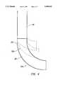
- FIG. 3is a cross sectional view of an optical fiber illustrating the reflection of a light ray in a linear section of the fiber, and the curved distal end.
- FIG. 4illustrates a toroidally curved fiber compared to an elliptically and parabolically or spherical curved fiber, all of which laterally direct the light at 90 degrees, but could be designed to direct the light at angles greater than or less than 90 degrees.
- FIG. 5illustrates a curved waveguide made from a fiber bundle.
- FIG. 6illustrates a high NA curved waveguide with low NA light, allowing a low index solid or liquid to clad the curved waveguide.
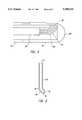
- FIG. 7is a cross sectional view of an optical delivery device.
- the linear section of the optical fiber and the curved distal endare two separate pieces.
- FIG. 8(A)is a sectional view of a cannula with a window and an output tip of the curved distal end of an optical fiber attached to the window.
- FIG. 8(B)is a top view of a cannula with a window and an output tip of the curved distal end of an optical fiber attached to the window.
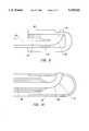
- FIG. 9is a cross sectional view of an optical delivery device that employs an optical fiber having a linear section, a curved distal end of the optical fiber, and a hollow cap attached to a distal end of the linear section, with an interior wall of the cap being fused to an output tip of the curved distal end.
- FIG. 10illustrates a metal cap with a hole for the distal tip of the curved waveguide to protrude.
- FIGS. 1(A) and 1(B)illustrate an optical delivery system 10, including an optical light source 12, an optical fiber 14 coupled to receive an output beam of light from optical light source 12, and a cannula 16 that houses optical fiber 14.
- Optical fiber 14extends beyond a distal end 18 of cannula 16. Attached to either optical fiber 14 or to the distal end 18 of cannula 16 is a hollow cap 20.
- Cannula 16can be a rigid tube or the lumen of an endoscope.
- Optical light source 12can be a laser, including but not limited to an Nd:YAG dual wavelength laser operating at 533 nm or 1064 nm, a solid state laser based on holmium thulium or erbium, a dye laser, or an incoherent light source.
- FIG. 2shows optical fiber 14 with a core 22, a cladding 24 surrounding the optical fiber core 22, and a buffer coating 25 that surrounds cladding 24.
- Optical fiber 14may be made of any material that transmits an optical output of light. Suitable materials include glass, quartz, crystals and plastics, including but not limited to polymethylmethacralate (PMMA), polycarbonate and certain liquids.
- Optical fiber 14has practically no size limitation. Preferred sizes are in the range of 100 to 1000 microns.
- FIG. 3illustrates an embodiment of the present invention where optical fiber 14 has a linear section 26, and a curved distal end 28 with a toroidal bend 30 in curved distal end 28.
- linear section 26 and curved distal end 28are collectively referred to as a curved waveguide 31.
- the bending lossescan be kept below 1% and the light reflected from distal output tip 32 can be kept below 6% in air, and less than 1% in water. There is very little light lost through reflections or other loss mechanisms. In air, all but 10%, and in water all but 5% of the output beam is delivered in the defined lateral direction.
- curvaturemeans substantially torodial or spherical, and can include parabolic, elliptical, hyperbola, and combinations thereof.
- FIG. 3shows that light 34 traveling down fiber optic 14 has a numerical aperture distribution.
- the most divergent light traveling down optical fiber 14has the highest numerical aperture.
- This high numerical aperture lightpropagates down linear section 26, totally internally reflecting off an optical fiber core/cladding interface.
- This most divergent lightstrikes curved distal end 28 of optical fiber 14 at a more acute angle than the light rays of lower numerical aperture. As optical fiber 14 is bent, this angle decreases until the condition for total internal reflection is no longer satisfied.
- all of the lower numerical aperture lightis also transmitted without loss around bend 30.
- a variety of curved waveguides 31can be used to laterally direct the light.
- One of the simplest to calculate and manufactureis a toroidal curve. For a tordial curve, there is a simple formula for the minimum bend radius optical fiber 14 can have before bending losses occur.
- n 1The refractive index of air ⁇ 1.
- n 2The refractive index of curved distal end 28 core.
- n 3The refractive index of the material surrounding the curved distal end 28.
- RThe radius of curvature measured to the outside of bend 30.
- ⁇The angle of light incident on linear fiber core 28.
- ⁇The angle of light refracted into the linear fiber core 28.
- ⁇The angle the highest NA Light strikes a line perpendicular to the surface of bend 30.
- NA FThe maximum numerical aperture of light 34 linear section 26 can transmit.
- the most divergent light ray 34enters linear section 26 at some NA L less than or equal to the numerical aperture of linear section 28.
- Light ray 34strikes linear section 28 core at an angle ⁇ and refracts at an internal angle ⁇ . This ray propagates down optical fiber 14 without its NA changing significantly.
- FIG. 4shows examples of toroidal 31a, elliptical 31b, and parabolic 31c curved waveguides 31 which direct the light 90 degrees with respect to the linear fiber axis.
- optical fiber 14As optical fiber 14 is bent with a radius of curvature less than R, the high NA light will leak out. In some instances, when small size is more important than transmission, this may be desirable.
- Optical fiber 14can always have a larger radius of curvature. This increases the size of the optical delivery device, and in some instances it may be easier to manufacture.
- FIG. 3shows optical fiber 14 bent at 90 degrees, it can be, if desired, diverted less than or more than 90 degrees.
- Table 1lists 24 examples of the minimum radii of curvature which will not produce bend losses for different fiber diameters, NA light, refractive index n 2 of the curved distal end 28, and refractive index n 3 of the material surrounding curved distal end 28.
- a fiber bundlecan be used for achieving sharp bend radii.
- fiber bundlesare extensively used to transmit light, they are used because they provide greater flexibility than a solid core fiber of the same diameter.
- the minimum bend radius achievable with a bundleis determined by applying a bend radius condition of the present invention to the fibers on the inside bend in the bundle. Most fiber bundles break if they are bent as sharply as the formula of Equation (4) implies; however, as with a single core fiber, the bundle can be thermally bent. This is particularly easy if the bundle is a rigid glass clad bundle.
- FIG. 6another embodiment of the invention relies on coupling low NA light into a high NA linear fiber section 26. Over short lengths, essentially none of light 14 is coupled to more divergent higher order modes. Because curved distal end 28 has a high NA, the light does not leak out of fiber 14 unless fiber 14 is bent too sharply.
- This methodhas the advantage of not needing to surround the curved distal end 28, with a gas in order to provide a high NA curved waveguide 31. Consequently, the need for hollow protective cap 20 is eliminated. For high NA glass clad fibers, the coating is striped, the fiber thermally bent and the protective coating reapplied.
- both the coatingis stripped off, the fiber thermally bent, the fiber cladding can be reapplied or alternatively a lower index cladding can be used.
- a protective coatingis applied.
- Another embodiment of the present inventionis to thermally bend, mold or grind and polish a waveguide to the desired shape.
- Thishas a higher refractive index than a linear fiber and is spliced to the linear fiber and surrounded with a material of low refractive index.
- the spliced embodimentis illustrated in FIG. 7.
- the present inventionextends beyond step index fibers and curved waveguides.
- the present inventionis suitable for graded index fibers with curved distal ends 28.
- the NA of curved distal end 28needs to be higher than the NA of the light in linear fiber section 26.
- the present inventionincludes GRIN fibers with curved distal ends 28. Additionally, linear fiber cross section 26 and curved distal end 28 need not be cylindrical.
- reflectionscan be reduced by keeping the number of surfaces to a minimum, and by anti-reflection coating and/or index matching them. This is the principle reason why it is desirable to fuse the distal tip of the curved waveguide to a window or a the inside of the capillary tube. In air approximately 5% of the light will be reflected back into curved waveguide 31 and a only a small fraction of which will escape through bend 30. In water the reflections are less than 1% and can be ignored.
- a glass core plastic clad multimode step index fiberis used, as shown in FIG. 9.
- Fiber buffer coating (not shown) and cladding 24are mechanically, chemically, or thermally removed from fiber 14. This region normally extends a few millimeters from curved distal end 28 of fiber 14.
- Optical fiber 14is then thermally bent, preferably 90 degrees, using preferably a laser, an electric arc, or a torch. The bend can be precisely controlled by using a mechanical force or gravity or the surface tension of thermally softened fiber 14 or any combination of these forces.
- Optical fiber 14is then trimmed to the required length using a cleaver, a precision saw, or by using precision grinding equipment.
- a closed end hollow cap 20is slid over the curved tip of the fiber as shown in FIG. 9.
- the outside faces of hollow cap 20 where curved distal tip 28 of curved waveguide 31 are adjacent to each othercan be ground flat.
- Hollow cap 20can also be frosted or anti reflection coated to minimize unwanted reflections.
- the distal end tip 32is placed in contact with the inner wall of hollow cap 20, and then thermally fused together by a laser, an electric arc or a torch.
- optical fiber 14is held securely in place and the 10% reflective losses at the fiber/air and air/hollow cap 20 interface are eliminated.
- Hollow cap 20can contain air, gas, a vacuum or various other media of low refractive index. Air is preferred. Fiber 14 is then sealed to fiber 14 on the linear portion of the fiber 14 using adhesives.
- a metal tubepreferably made from a platinum alloy is used instead of a glass hollow cap 20.
- a metal tube 38is sealed at one end and a hole is made in the side of the tube for curved waveguide 31 to fit through. After curved distal end 28 of curved waveguide 31 has been placed through tube 38, it is thermally melted and fused to the outside of metal tube 38. Adhesive is then used to seal metal tube 38 to linear section 26 of fiber 14.
- a high NA curved waveguide 31, with low NA lightincludes a low index solid or liquid 40 to clad curved waveguide 31.
Landscapes
- Physics & Mathematics (AREA)
- Health & Medical Sciences (AREA)
- Life Sciences & Earth Sciences (AREA)
- Surgery (AREA)
- Optics & Photonics (AREA)
- Heart & Thoracic Surgery (AREA)
- Medical Informatics (AREA)
- Nuclear Medicine, Radiotherapy & Molecular Imaging (AREA)
- General Physics & Mathematics (AREA)
- Engineering & Computer Science (AREA)
- Biomedical Technology (AREA)
- Electromagnetism (AREA)
- Otolaryngology (AREA)
- Molecular Biology (AREA)
- Animal Behavior & Ethology (AREA)
- General Health & Medical Sciences (AREA)
- Public Health (AREA)
- Veterinary Medicine (AREA)
- Endoscopes (AREA)
Abstract
Description
ψ=Sin.sup.-1 (n.sub.3 n.sub.2)
ψ≧sin.sup.-1 [n.sub.3 /n.sub.2 ] Equation (1)
R≧D.{1/[1-sin ψ/cos θ]} Equation (2)TABLE 1______________________________________R(mm) NA N.sub.2 N.sub.3 Dmm______________________________________ 1 0.611 0.2 2 0.916 0.3 3 1.22 0.2 1.5 1 0.4 4 1.83 0.6 5 3.06 1 6 1.2 0 7 1.22 0.2 8 1.3 0.4 1.5 1 0.4 9 1.47 0.610 3.81 111 112 1.81 1.313 1.22 1.514 1.08 0.2 1.6 1 0.415 0.98 1.716 0.91 1.817 1.22 118 2.5 1.319 5.28 0.2 1.5 1.4 0.420 1.521 1.74 0.2 1.322 3.59 1 1.5 0.423 1.46 0.2 1.8 1.324 2.48 1.8 1.5______________________________________
Claims (31)
Priority Applications (1)
| Application Number | Priority Date | Filing Date | Title |
|---|---|---|---|
| US08/229,598US5495541A (en) | 1994-04-19 | 1994-04-19 | Optical delivery device with high numerical aperture curved waveguide |
Applications Claiming Priority (1)
| Application Number | Priority Date | Filing Date | Title |
|---|---|---|---|
| US08/229,598US5495541A (en) | 1994-04-19 | 1994-04-19 | Optical delivery device with high numerical aperture curved waveguide |
Publications (1)
| Publication Number | Publication Date |
|---|---|
| US5495541Atrue US5495541A (en) | 1996-02-27 |
Family
ID=22861919
Family Applications (1)
| Application Number | Title | Priority Date | Filing Date |
|---|---|---|---|
| US08/229,598Expired - Fee RelatedUS5495541A (en) | 1994-04-19 | 1994-04-19 | Optical delivery device with high numerical aperture curved waveguide |
Country Status (1)
| Country | Link |
|---|---|
| US (1) | US5495541A (en) |
Cited By (94)
| Publication number | Priority date | Publication date | Assignee | Title |
|---|---|---|---|---|
| US5688263A (en)* | 1994-12-22 | 1997-11-18 | Dornier Medizintechnik Gmbh | Laser surgery applicator |
| EP0827719A1 (en)* | 1996-09-06 | 1998-03-11 | Kaltenbach & Voigt Gmbh & Co. | Medical or dental laser instrument, in particular for treating dental root canals |
| US5738676A (en)* | 1995-01-03 | 1998-04-14 | Hammer; Daniel X. | Laser surgical probe for use in intraocular surgery |
| US5746737A (en)* | 1995-06-07 | 1998-05-05 | Trimedyne, Inc. | Enclosure for a lasing device |
| US5807383A (en)* | 1996-05-13 | 1998-09-15 | United States Surgical Corporation | Lasing device |
| WO1998055888A1 (en)* | 1997-06-06 | 1998-12-10 | Optomedic Medical Technologies Ltd. | Laser probe |
| US5951543A (en)* | 1997-06-30 | 1999-09-14 | Clinicon Corporation | Delivery system and method for surgical laser |
| US5956447A (en)* | 1996-05-07 | 1999-09-21 | Univ Central Florida | Device and method for image acquisition through multi-mode fiber |
| US6135996A (en)* | 1998-04-17 | 2000-10-24 | Baxter International, Inc. | Controlled advancement lasing device |
| US6283955B1 (en) | 1996-05-13 | 2001-09-04 | Edwards Lifesciences Corp. | Laser ablation device |
| US6314219B1 (en)* | 1999-09-23 | 2001-11-06 | Jds Uniphase Corporation | Fiber mini-bend light guide |
| US6421164B2 (en) | 1991-04-29 | 2002-07-16 | Massachusetts Institute Of Technology | Interferometeric imaging with a grating based phase control optical delay line |
| US6445939B1 (en) | 1999-08-09 | 2002-09-03 | Lightlab Imaging, Llc | Ultra-small optical probes, imaging optics, and methods for using same |
| US6485413B1 (en) | 1991-04-29 | 2002-11-26 | The General Hospital Corporation | Methods and apparatus for forward-directed optical scanning instruments |
| US6554824B2 (en)* | 2000-12-15 | 2003-04-29 | Laserscope | Methods for laser treatment of soft tissue |
| US6564087B1 (en) | 1991-04-29 | 2003-05-13 | Massachusetts Institute Of Technology | Fiber optic needle probes for optical coherence tomography imaging |
| US20030130649A1 (en)* | 2000-12-15 | 2003-07-10 | Murray Steven C. | Method and system for treatment of benign prostatic hypertrophy (BPH) |
| US20030135205A1 (en)* | 2000-12-15 | 2003-07-17 | Davenport Scott A. | Method and system for photoselective vaporization of the prostate, and other tissue |
| US20030165313A1 (en)* | 2001-08-30 | 2003-09-04 | Jes Broeng | Optical fibre with high numerical aperture, method of its production, and use thereof |
| US20030216717A1 (en)* | 2002-02-22 | 2003-11-20 | Laserscope | Method and system for photoselective vaporization for gynecological treatments |
| US6658896B2 (en) | 2002-01-18 | 2003-12-09 | Sunoptic Technologies Llc | Method of making a fiberoptic light guide |
| US20040101230A1 (en)* | 2002-11-26 | 2004-05-27 | Peter Philebrown | Optical arrangement with a low-radius fiber bend |
| US20040112877A1 (en)* | 2002-12-12 | 2004-06-17 | 3M Innovative Properties Company | Optical fiber or waveguide lens |
| US20060132790A1 (en)* | 2003-02-20 | 2006-06-22 | Applied Science Innovations, Inc. | Optical coherence tomography with 3d coherence scanning |
| US20060224148A1 (en)* | 2005-04-05 | 2006-10-05 | Cho George E | System and method for laser lipolysis |
| US20060285793A1 (en)* | 2005-06-17 | 2006-12-21 | Medical Cv, Inc. | Side-firing laser |
| US20060285798A1 (en)* | 2005-06-17 | 2006-12-21 | Medical Cv, Inc. | Bent side-firing laser |
| US20070054319A1 (en)* | 2005-07-22 | 2007-03-08 | Boyden Edward S | Light-activated cation channel and uses thereof |
| US20070260231A1 (en)* | 2005-04-21 | 2007-11-08 | Ondine International, Ltd. | Optical probe for delivery of light |
| US20080085265A1 (en)* | 2005-07-22 | 2008-04-10 | Schneider M B | System for optical stimulation of target cells |
| US20080188843A1 (en)* | 2002-07-10 | 2008-08-07 | Appling William M | Device and method for endovascular treatment for causing closure of a blood vessel |
| US20080287936A1 (en)* | 2007-05-18 | 2008-11-20 | Stinson Douglas G | Telescope with Integrated Optical Filter |
| US20080287940A1 (en)* | 2007-05-14 | 2008-11-20 | Hunter Lowell D | Fiber Pole Tip |
| US20080287934A1 (en)* | 2007-05-15 | 2008-11-20 | Hunter Lowell D | Laser Handle and Fiber Guard |
| US20090088680A1 (en)* | 2005-07-22 | 2009-04-02 | Alexander Aravanis | Optical tissue interface method and apparatus for stimulating cells |
| US20090099038A1 (en)* | 2005-07-22 | 2009-04-16 | Karl Deisseroth | Cell line, system and method for optical-based screening of ion-channel modulators |
| US20090112133A1 (en)* | 2007-10-31 | 2009-04-30 | Karl Deisseroth | Device and method for non-invasive neuromodulation |
| US20090118800A1 (en)* | 2007-10-31 | 2009-05-07 | Karl Deisseroth | Implantable optical stimulators |
| US20090287197A1 (en)* | 2008-05-19 | 2009-11-19 | Hanley Brian M | Side-firing laser fiber with internal bent fiber and related methods |
| US20100016845A1 (en)* | 2008-05-19 | 2010-01-21 | Brian Hanley | Method and apparatus for protecting capillary of laser fiber during insertion and reducing metal cap degradation |
| US20100135617A1 (en)* | 2008-12-01 | 2010-06-03 | Ams Research Corporation | Optical device |
| US20100190229A1 (en)* | 2005-07-22 | 2010-07-29 | Feng Zhang | System for optical stimulation of target cells |
| US20100331782A1 (en)* | 2008-03-03 | 2010-12-30 | Koninklijke Philips Electronics N.V. | Biopsy guidance by image-based x-ray guidance system and photonic needle |
| US20110002584A1 (en)* | 2006-12-07 | 2011-01-06 | Ams Research Corporation | Annular side fire optical device for laterally redirecting electromagnetic radiation |
| US20110105998A1 (en)* | 2008-04-23 | 2011-05-05 | The Board Of Trustees Of The Leland Stanford Junio | Systems, methods and compositions for optical stimulation of target cells |
| US20110112179A1 (en)* | 2008-05-29 | 2011-05-12 | Airan Raag D | Cell line, system and method for optical control of secondary messengers |
| US20110149589A1 (en)* | 2008-07-30 | 2011-06-23 | Ams Research Corporation | Optical device having fluorocarbon polymer layer |
| US20110159562A1 (en)* | 2008-06-17 | 2011-06-30 | Karl Deisseroth | Apparatus and methods for controlling cellular development |
| US20110166632A1 (en)* | 2008-07-08 | 2011-07-07 | Delp Scott L | Materials and approaches for optical stimulation of the peripheral nervous system |
| US20110172653A1 (en)* | 2008-06-17 | 2011-07-14 | Schneider M Bret | Methods, systems and devices for optical stimulation of target cells using an optical transmission element |
| US20110319757A1 (en)* | 2009-12-22 | 2011-12-29 | Ceramoptec Industries Inc. | Tissue resection under image guidance/control |
| US20120271113A1 (en)* | 2011-04-21 | 2012-10-25 | Fang Lei | Light-conducting device for an endoscope to direct illuminating light |
| DE102011118875A1 (en)* | 2011-11-19 | 2013-05-23 | Advanced Fiber Tools Gmbh | Device for medical treatment, in particular of a tissue, by means of laser light |
| DE102012013025A1 (en)* | 2012-07-02 | 2013-09-19 | Advanced Fiber Tools Gmbh | Treatment device i.e. applicator, for e.g. ablation of living prostate tissue by laser light, has microstructured-multimode optical fiber whose light exit end is designed curved and includes open tubes, which extend in exit direction |
| US20130274727A1 (en)* | 2012-04-17 | 2013-10-17 | Tyco Healthcare Group Lp | Surgical system and method of use of the same |
| US8696722B2 (en) | 2010-11-22 | 2014-04-15 | The Board Of Trustees Of The Leland Stanford Junior University | Optogenetic magnetic resonance imaging |
| US8716447B2 (en) | 2008-11-14 | 2014-05-06 | The Board Of Trustees Of The Leland Stanford Junior University | Optically-based stimulation of target cells and modifications thereto |
| US8864805B2 (en) | 2007-01-10 | 2014-10-21 | The Board Of Trustees Of The Leland Stanford Junior University | System for optical stimulation of target cells |
| US8932562B2 (en) | 2010-11-05 | 2015-01-13 | The Board Of Trustees Of The Leland Stanford Junior University | Optically controlled CNS dysfunction |
| US20150150442A1 (en)* | 2012-06-05 | 2015-06-04 | The Regents Of The University Of California | Endovascular probe |
| WO2015088510A1 (en)* | 2013-12-11 | 2015-06-18 | Empire Technology Development Llc | Preparation and usage of optical waveguides |
| US9079940B2 (en) | 2010-03-17 | 2015-07-14 | The Board Of Trustees Of The Leland Stanford Junior University | Light-sensitive ion-passing molecules |
| US9175095B2 (en) | 2010-11-05 | 2015-11-03 | The Board Of Trustees Of The Leland Stanford Junior University | Light-activated chimeric opsins and methods of using the same |
| US9284353B2 (en) | 2007-03-01 | 2016-03-15 | The Board Of Trustees Of The Leland Stanford Junior University | Mammalian codon optimized nucleotide sequence that encodes a variant opsin polypeptide derived from Natromonas pharaonis (NpHR) |
| US9323005B1 (en) | 2014-12-22 | 2016-04-26 | InnovaQuartz LLC | Redirecting electromagnetic radiation |
| US20160114868A1 (en)* | 2014-10-24 | 2016-04-28 | John Burke | Light conduit underwater illumination system |
| US9365628B2 (en) | 2011-12-16 | 2016-06-14 | The Board Of Trustees Of The Leland Stanford Junior University | Opsin polypeptides and methods of use thereof |
| US9488782B2 (en) | 2014-12-22 | 2016-11-08 | InnovaQuartz LLC | Redirecting electromagnetic radiation |
| US9500820B2 (en) | 2014-10-20 | 2016-11-22 | Foxconn Interconnect Technology Limited | Fiber assembly |
| US9522288B2 (en) | 2010-11-05 | 2016-12-20 | The Board Of Trustees Of The Leland Stanford Junior University | Upconversion of light for use in optogenetic methods |
| US9618700B1 (en) | 2015-12-03 | 2017-04-11 | InnovaQuartz LLC | Orthogonal output optical fiber |
| US9636380B2 (en) | 2013-03-15 | 2017-05-02 | The Board Of Trustees Of The Leland Stanford Junior University | Optogenetic control of inputs to the ventral tegmental area |
| US9662173B1 (en) | 2015-12-24 | 2017-05-30 | Cyclone Biosciences LLC | Lateral delivery device with active cooling |
| US9693692B2 (en) | 2007-02-14 | 2017-07-04 | The Board Of Trustees Of The Leland Stanford Junior University | System, method and applications involving identification of biological circuits such as neurological characteristics |
| US9782562B2 (en) | 2002-04-04 | 2017-10-10 | Angiodynamics, Inc. | Venous insufficiency treatment method |
| US9814513B2 (en) | 2011-06-30 | 2017-11-14 | Angiodynamics, Inc. | Endovascular plasma treatment device and method of use |
| US9992981B2 (en) | 2010-11-05 | 2018-06-12 | The Board Of Trustees Of The Leland Stanford Junior University | Optogenetic control of reward-related behaviors |
| US10086012B2 (en) | 2010-11-05 | 2018-10-02 | The Board Of Trustees Of The Leland Stanford Junior University | Control and characterization of memory function |
| US10092356B2 (en) | 2015-11-18 | 2018-10-09 | InnovaQuartz LLC | Radial emissions from optical fibers |
| US10220092B2 (en) | 2013-04-29 | 2019-03-05 | The Board Of Trustees Of The Leland Stanford Junior University | Devices, systems and methods for optogenetic modulation of action potentials in target cells |
| US10307609B2 (en) | 2013-08-14 | 2019-06-04 | The Board Of Trustees Of The Leland Stanford Junior University | Compositions and methods for controlling pain |
| US20190216485A1 (en)* | 2013-09-06 | 2019-07-18 | Procept Biorobotics Corporation | Tissue treatment probe with bent optical fiber |
| US10568307B2 (en) | 2010-11-05 | 2020-02-25 | The Board Of Trustees Of The Leland Stanford Junior University | Stabilized step function opsin proteins and methods of using the same |
| US10568516B2 (en) | 2015-06-22 | 2020-02-25 | The Board Of Trustees Of The Leland Stanford Junior University | Methods and devices for imaging and/or optogenetic control of light-responsive neurons |
| US10974064B2 (en) | 2013-03-15 | 2021-04-13 | The Board Of Trustees Of The Leland Stanford Junior University | Optogenetic control of behavioral state |
| WO2021075141A1 (en)* | 2019-10-17 | 2021-04-22 | 朝日インテック株式会社 | Light irradiation device and light irradiation system |
| US11103723B2 (en) | 2012-02-21 | 2021-08-31 | The Board Of Trustees Of The Leland Stanford Junior University | Methods for treating neurogenic disorders of the pelvic floor |
| US11294165B2 (en) | 2017-03-30 | 2022-04-05 | The Board Of Trustees Of The Leland Stanford Junior University | Modular, electro-optical device for increasing the imaging field of view using time-sequential capture |
| US11576724B2 (en) | 2011-02-24 | 2023-02-14 | Eximo Medical Ltd. | Hybrid catheter for vascular intervention |
| US11684420B2 (en) | 2016-05-05 | 2023-06-27 | Eximo Medical Ltd. | Apparatus and methods for resecting and/or ablating an undesired tissue |
| EP4046586A4 (en)* | 2019-10-17 | 2023-11-15 | Asahi Intecc Co., Ltd. | LIGHT EMITTING DEVICE AND LIGHT EMITTING SYSTEM |
| US11826097B2 (en) | 2015-11-18 | 2023-11-28 | Cyclone Biosciences, Llc | Forming radial emissions from optical fibers |
| US12038322B2 (en) | 2022-06-21 | 2024-07-16 | Eximo Medical Ltd. | Devices and methods for testing ablation systems |
| US12376904B1 (en) | 2020-09-08 | 2025-08-05 | Angiodynamics, Inc. | Dynamic laser stabilization and calibration system |
Citations (23)
| Publication number | Priority date | Publication date | Assignee | Title |
|---|---|---|---|---|
| US4076377A (en)* | 1975-02-19 | 1978-02-28 | Volpi Ag | Fiber-optic device with curved sleeve and filler matrix |
| EP0069351A2 (en)* | 1981-07-02 | 1983-01-12 | Sumitomo Electric Industries Limited | Hand piece for use with surgical laser knife device |
| US4503853A (en)* | 1981-09-04 | 1985-03-12 | Kabushiki Kaisha Morita Seisakusho | Contra angle handpiece for dental treatment by laser beams |
| US4538609A (en)* | 1981-07-07 | 1985-09-03 | Sumitomo Electric Industries, Ltd. | Manipulator for laser knife |
| US4576147A (en)* | 1981-07-16 | 1986-03-18 | Olympus Optical Co., Ltd. | Hard endoscope with improved light dispersion |
| US4592353A (en)* | 1984-05-22 | 1986-06-03 | Surgical Laser Technologies Ohio, Inc. | Medical and surgical laser probe |
| US4736743A (en)* | 1986-05-12 | 1988-04-12 | Surgical Laser Technology, Inc. | Vaporization contact laser probe |
| US4740047A (en)* | 1985-03-26 | 1988-04-26 | Hatachi Cable, Ltd. | Fiber for lateral beaming of laser beam |
| US4787689A (en)* | 1985-05-03 | 1988-11-29 | American Telephone And Telegraph Company, At&T Bell Laboratories | Devices having low loss curved or tapered optical waveguides |
| US5037174A (en)* | 1990-01-31 | 1991-08-06 | E. I. Du Pont De Nemours And Company | Optical fiber having an aspherical lens thereon and method of making same |
| US5042980A (en)* | 1989-05-26 | 1991-08-27 | C. R. Bard, Inc. | Optical fiber diffusion tip for uniform illumination |
| US5078711A (en)* | 1988-08-11 | 1992-01-07 | Kabushiki Kaisha Morita Seisakusho | Laser irradiation device capable of varying irradiation angle |
| US5100507A (en)* | 1991-01-31 | 1992-03-31 | At&T Bell Laboratories | Finishing techniques for lensed optical fibers |
| US5129897A (en)* | 1989-02-15 | 1992-07-14 | S.L.T. Japan Co., Ltd. | Curved laser light emitter |
| US5154708A (en)* | 1990-05-15 | 1992-10-13 | Surgical Laser Technologies, Inc. | Unitary scalpel for contact laser surgery |
| US5164945A (en)* | 1991-07-01 | 1992-11-17 | Laser Centers Of America, Inc. | Laser device with intermediate refraction index layer for reduced fresnel losses |
| US5207669A (en)* | 1989-05-26 | 1993-05-04 | C. R. Bard, Inc. | Optical fiber diffusion tip for uniform illumination |
| US5221279A (en)* | 1990-10-12 | 1993-06-22 | Surgical Laser Technologies, Inc. | Adjustable touch control handpiece |
| US5257991A (en)* | 1990-11-15 | 1993-11-02 | Laserscope | Instrumentation for directing light at an angle |
| US5267995A (en)* | 1992-09-01 | 1993-12-07 | Pdt Systems | Optical waveguide with flexible tip |
| US5274227A (en)* | 1992-10-23 | 1993-12-28 | Applied Biosystems, Inc. | Capillary detector cell having imaging elements positioned to optimize sensitivity |
| US5371826A (en)* | 1993-08-27 | 1994-12-06 | Demetron Research Corp. | Dental fiber optic light bundle with uniform taper |
| US5394492A (en)* | 1993-11-19 | 1995-02-28 | Applied Optronics Corporation | High power semiconductor laser system |
- 1994
- 1994-04-19USUS08/229,598patent/US5495541A/ennot_activeExpired - Fee Related
Patent Citations (24)
| Publication number | Priority date | Publication date | Assignee | Title |
|---|---|---|---|---|
| US4076377A (en)* | 1975-02-19 | 1978-02-28 | Volpi Ag | Fiber-optic device with curved sleeve and filler matrix |
| EP0069351A2 (en)* | 1981-07-02 | 1983-01-12 | Sumitomo Electric Industries Limited | Hand piece for use with surgical laser knife device |
| US4538609A (en)* | 1981-07-07 | 1985-09-03 | Sumitomo Electric Industries, Ltd. | Manipulator for laser knife |
| US4576147A (en)* | 1981-07-16 | 1986-03-18 | Olympus Optical Co., Ltd. | Hard endoscope with improved light dispersion |
| US4503853A (en)* | 1981-09-04 | 1985-03-12 | Kabushiki Kaisha Morita Seisakusho | Contra angle handpiece for dental treatment by laser beams |
| US4592353A (en)* | 1984-05-22 | 1986-06-03 | Surgical Laser Technologies Ohio, Inc. | Medical and surgical laser probe |
| US4592353B1 (en)* | 1984-05-22 | 1989-04-18 | ||
| US4740047A (en)* | 1985-03-26 | 1988-04-26 | Hatachi Cable, Ltd. | Fiber for lateral beaming of laser beam |
| US4787689A (en)* | 1985-05-03 | 1988-11-29 | American Telephone And Telegraph Company, At&T Bell Laboratories | Devices having low loss curved or tapered optical waveguides |
| US4736743A (en)* | 1986-05-12 | 1988-04-12 | Surgical Laser Technology, Inc. | Vaporization contact laser probe |
| US5078711A (en)* | 1988-08-11 | 1992-01-07 | Kabushiki Kaisha Morita Seisakusho | Laser irradiation device capable of varying irradiation angle |
| US5129897A (en)* | 1989-02-15 | 1992-07-14 | S.L.T. Japan Co., Ltd. | Curved laser light emitter |
| US5207669A (en)* | 1989-05-26 | 1993-05-04 | C. R. Bard, Inc. | Optical fiber diffusion tip for uniform illumination |
| US5042980A (en)* | 1989-05-26 | 1991-08-27 | C. R. Bard, Inc. | Optical fiber diffusion tip for uniform illumination |
| US5037174A (en)* | 1990-01-31 | 1991-08-06 | E. I. Du Pont De Nemours And Company | Optical fiber having an aspherical lens thereon and method of making same |
| US5154708A (en)* | 1990-05-15 | 1992-10-13 | Surgical Laser Technologies, Inc. | Unitary scalpel for contact laser surgery |
| US5221279A (en)* | 1990-10-12 | 1993-06-22 | Surgical Laser Technologies, Inc. | Adjustable touch control handpiece |
| US5257991A (en)* | 1990-11-15 | 1993-11-02 | Laserscope | Instrumentation for directing light at an angle |
| US5100507A (en)* | 1991-01-31 | 1992-03-31 | At&T Bell Laboratories | Finishing techniques for lensed optical fibers |
| US5164945A (en)* | 1991-07-01 | 1992-11-17 | Laser Centers Of America, Inc. | Laser device with intermediate refraction index layer for reduced fresnel losses |
| US5267995A (en)* | 1992-09-01 | 1993-12-07 | Pdt Systems | Optical waveguide with flexible tip |
| US5274227A (en)* | 1992-10-23 | 1993-12-28 | Applied Biosystems, Inc. | Capillary detector cell having imaging elements positioned to optimize sensitivity |
| US5371826A (en)* | 1993-08-27 | 1994-12-06 | Demetron Research Corp. | Dental fiber optic light bundle with uniform taper |
| US5394492A (en)* | 1993-11-19 | 1995-02-28 | Applied Optronics Corporation | High power semiconductor laser system |
Cited By (208)
| Publication number | Priority date | Publication date | Assignee | Title |
|---|---|---|---|---|
| US6485413B1 (en) | 1991-04-29 | 2002-11-26 | The General Hospital Corporation | Methods and apparatus for forward-directed optical scanning instruments |
| US6421164B2 (en) | 1991-04-29 | 2002-07-16 | Massachusetts Institute Of Technology | Interferometeric imaging with a grating based phase control optical delay line |
| US6564087B1 (en) | 1991-04-29 | 2003-05-13 | Massachusetts Institute Of Technology | Fiber optic needle probes for optical coherence tomography imaging |
| US5688263A (en)* | 1994-12-22 | 1997-11-18 | Dornier Medizintechnik Gmbh | Laser surgery applicator |
| US5738676A (en)* | 1995-01-03 | 1998-04-14 | Hammer; Daniel X. | Laser surgical probe for use in intraocular surgery |
| US5746737A (en)* | 1995-06-07 | 1998-05-05 | Trimedyne, Inc. | Enclosure for a lasing device |
| US5956447A (en)* | 1996-05-07 | 1999-09-21 | Univ Central Florida | Device and method for image acquisition through multi-mode fiber |
| US6283955B1 (en) | 1996-05-13 | 2001-09-04 | Edwards Lifesciences Corp. | Laser ablation device |
| US5807383A (en)* | 1996-05-13 | 1998-09-15 | United States Surgical Corporation | Lasing device |
| EP0827719A1 (en)* | 1996-09-06 | 1998-03-11 | Kaltenbach & Voigt Gmbh & Co. | Medical or dental laser instrument, in particular for treating dental root canals |
| WO1998055888A1 (en)* | 1997-06-06 | 1998-12-10 | Optomedic Medical Technologies Ltd. | Laser probe |
| US5951543A (en)* | 1997-06-30 | 1999-09-14 | Clinicon Corporation | Delivery system and method for surgical laser |
| US6135996A (en)* | 1998-04-17 | 2000-10-24 | Baxter International, Inc. | Controlled advancement lasing device |
| US6445939B1 (en) | 1999-08-09 | 2002-09-03 | Lightlab Imaging, Llc | Ultra-small optical probes, imaging optics, and methods for using same |
| US6314219B1 (en)* | 1999-09-23 | 2001-11-06 | Jds Uniphase Corporation | Fiber mini-bend light guide |
| US20050256513A1 (en)* | 2000-12-15 | 2005-11-17 | Laserscope | Method and system for vaporization of tissue using direct visualization |
| US20060084959A1 (en)* | 2000-12-15 | 2006-04-20 | Laserscope | Method and system for photoselective vaporization of the prostate, and other tissue |
| US20030135205A1 (en)* | 2000-12-15 | 2003-07-17 | Davenport Scott A. | Method and system for photoselective vaporization of the prostate, and other tissue |
| US20140221989A1 (en)* | 2000-12-15 | 2014-08-07 | Laserscope | Method and system for photoselective vaporization of the prostate, and other tissue |
| US10653482B2 (en)* | 2000-12-15 | 2020-05-19 | Boston Scientific Scimed, Inc. | System for vaporization of tissue |
| US20030130649A1 (en)* | 2000-12-15 | 2003-07-10 | Murray Steven C. | Method and system for treatment of benign prostatic hypertrophy (BPH) |
| US20070225696A1 (en)* | 2000-12-15 | 2007-09-27 | Davenport Scott A | Surgical apparatus for laser ablation of soft tissue |
| US6986764B2 (en) | 2000-12-15 | 2006-01-17 | Laserscope | Method and system for photoselective vaporization of the prostate, and other tissue |
| US6554824B2 (en)* | 2000-12-15 | 2003-04-29 | Laserscope | Methods for laser treatment of soft tissue |
| US20040236319A1 (en)* | 2000-12-15 | 2004-11-25 | Laserscope | Method and system for photoselective vaporization of the prostate, and other tissue |
| US20080262485A1 (en)* | 2000-12-15 | 2008-10-23 | Laserscope | Method and system for photoselective vaporization of the prostate, and other tissue |
| US20040236318A1 (en)* | 2000-12-15 | 2004-11-25 | Laserscope | Method and system for photoselective vaporization of the prostate, and other tissue |
| US7590323B2 (en)* | 2001-08-30 | 2009-09-15 | Crystal Fibre A/S | Optical fibre with high numerical aperture, method of its production, and use thereof |
| US20030165313A1 (en)* | 2001-08-30 | 2003-09-04 | Jes Broeng | Optical fibre with high numerical aperture, method of its production, and use thereof |
| US6807344B2 (en) | 2002-01-18 | 2004-10-19 | Sunoptic Technologies Llc | Method of making a fiberoptic light guide |
| US20040081423A1 (en)* | 2002-01-18 | 2004-04-29 | Antonio Galarza | Method of making a fiberoptic light guide |
| US6658896B2 (en) | 2002-01-18 | 2003-12-09 | Sunoptic Technologies Llc | Method of making a fiberoptic light guide |
| US20050177145A1 (en)* | 2002-02-22 | 2005-08-11 | Laserscope | Method and system for photoselective vaporization for gynecological treatments |
| US7063694B2 (en) | 2002-02-22 | 2006-06-20 | Laserscope | Method and system for photoselective vaporization for gynecological treatments |
| US20030216717A1 (en)* | 2002-02-22 | 2003-11-20 | Laserscope | Method and system for photoselective vaporization for gynecological treatments |
| US9782562B2 (en) | 2002-04-04 | 2017-10-10 | Angiodynamics, Inc. | Venous insufficiency treatment method |
| US20080188843A1 (en)* | 2002-07-10 | 2008-08-07 | Appling William M | Device and method for endovascular treatment for causing closure of a blood vessel |
| US10238453B2 (en) | 2002-07-10 | 2019-03-26 | Angiodynamics, Inc. | Method of making an endovascular laser treatment device for causing closure of a blood vessel |
| US8864754B2 (en)* | 2002-07-10 | 2014-10-21 | Angiodynamics, Inc. | Device and method for endovascular treatment for causing closure of a blood vessel |
| US20040101230A1 (en)* | 2002-11-26 | 2004-05-27 | Peter Philebrown | Optical arrangement with a low-radius fiber bend |
| US20040112877A1 (en)* | 2002-12-12 | 2004-06-17 | 3M Innovative Properties Company | Optical fiber or waveguide lens |
| US6822190B2 (en) | 2002-12-12 | 2004-11-23 | 3M Innovative Properties Company | Optical fiber or waveguide lens |
| US7474407B2 (en) | 2003-02-20 | 2009-01-06 | Applied Science Innovations | Optical coherence tomography with 3d coherence scanning |
| US20060132790A1 (en)* | 2003-02-20 | 2006-06-22 | Applied Science Innovations, Inc. | Optical coherence tomography with 3d coherence scanning |
| US20060224148A1 (en)* | 2005-04-05 | 2006-10-05 | Cho George E | System and method for laser lipolysis |
| EP1992301A1 (en)* | 2005-04-05 | 2008-11-19 | EL.EN. S.p.A. | System and method for laser lipolysis |
| US20070219540A1 (en)* | 2005-04-05 | 2007-09-20 | El.En. S.p.A | Sub-dermal laser skin treatment |
| US8113209B2 (en) | 2005-04-05 | 2012-02-14 | Cynosure, Inc. | Sub-dermal laser skin treatment |
| US7975702B2 (en) | 2005-04-05 | 2011-07-12 | El.En. S.P.A. | System and method for laser lipolysis |
| WO2006107522A3 (en)* | 2005-04-05 | 2007-03-22 | El En Spa | System and method for laser lipolysis |
| US20070260231A1 (en)* | 2005-04-21 | 2007-11-08 | Ondine International, Ltd. | Optical probe for delivery of light |
| US20060285793A1 (en)* | 2005-06-17 | 2006-12-21 | Medical Cv, Inc. | Side-firing laser |
| US20060285798A1 (en)* | 2005-06-17 | 2006-12-21 | Medical Cv, Inc. | Bent side-firing laser |
| US7463801B2 (en) | 2005-06-17 | 2008-12-09 | Medical Cv, Inc. | Side-firing laser |
| WO2006138128A3 (en)* | 2005-06-17 | 2007-06-07 | Medical Cv Inc | Laterally firing optical fiber with aw inclined end surface as light redirecting means confined in a tubular member |
| US20090092359A1 (en)* | 2005-06-17 | 2009-04-09 | Medical Cv, Inc. | Side-firing laser |
| US10036758B2 (en) | 2005-07-22 | 2018-07-31 | The Board Of Trustees Of The Leland Stanford Junior University | Delivery of a light-activated cation channel into the brain of a subject |
| US9278159B2 (en) | 2005-07-22 | 2016-03-08 | The Board Of Trustees Of The Leland Stanford Junior University | Light-activated cation channel and uses thereof |
| US9101690B2 (en) | 2005-07-22 | 2015-08-11 | The Board Of Trustees Of The Leland Stanford Junior University | Light-activated cation channel and uses thereof |
| US20090099038A1 (en)* | 2005-07-22 | 2009-04-16 | Karl Deisseroth | Cell line, system and method for optical-based screening of ion-channel modulators |
| US20070054319A1 (en)* | 2005-07-22 | 2007-03-08 | Boyden Edward S | Light-activated cation channel and uses thereof |
| US10094840B2 (en) | 2005-07-22 | 2018-10-09 | The Board Of Trustees Of The Leland Stanford Junior University | Light-activated cation channel and uses thereof |
| US10052497B2 (en) | 2005-07-22 | 2018-08-21 | The Board Of Trustees Of The Leland Stanford Junior University | System for optical stimulation of target cells |
| US20100190229A1 (en)* | 2005-07-22 | 2010-07-29 | Feng Zhang | System for optical stimulation of target cells |
| US20100234273A1 (en)* | 2005-07-22 | 2010-09-16 | The Board Of Trustees Of The Leland Stanford Junior University | Light-activated cation channel and uses thereof |
| US10451608B2 (en) | 2005-07-22 | 2019-10-22 | The Board Of Trustees Of The Leland Stanford Junior University | Cell line, system and method for optical-based screening of ion-channel modulators |
| US10627410B2 (en) | 2005-07-22 | 2020-04-21 | The Board Of Trustees Of The Leland Stanford Junior University | Light-activated cation channel and uses thereof |
| US9360472B2 (en) | 2005-07-22 | 2016-06-07 | The Board Of Trustees Of The Leland Stanford Junior University | Cell line, system and method for optical-based screening of ion-channel modulators |
| US8926959B2 (en) | 2005-07-22 | 2015-01-06 | The Board Of Trustees Of The Leland Stanford Junior University | System for optical stimulation of target cells |
| US20080085265A1 (en)* | 2005-07-22 | 2008-04-10 | Schneider M B | System for optical stimulation of target cells |
| US20090088680A1 (en)* | 2005-07-22 | 2009-04-02 | Alexander Aravanis | Optical tissue interface method and apparatus for stimulating cells |
| US10569099B2 (en) | 2005-07-22 | 2020-02-25 | The Board Of Trustees Of The Leland Stanford Junior University | System for optical stimulation of target cells |
| US9829492B2 (en) | 2005-07-22 | 2017-11-28 | The Board Of Trustees Of The Leland Stanford Junior University | Implantable prosthetic device comprising a cell expressing a channelrhodopsin |
| US8906360B2 (en) | 2005-07-22 | 2014-12-09 | The Board Of Trustees Of The Leland Stanford Junior University | Light-activated cation channel and uses thereof |
| US10046174B2 (en) | 2005-07-22 | 2018-08-14 | The Board Of Trustees Of The Leland Stanford Junior University | System for electrically stimulating target neuronal cells of a living animal in vivo |
| US9238150B2 (en) | 2005-07-22 | 2016-01-19 | The Board Of Trustees Of The Leland Stanford Junior University | Optical tissue interface method and apparatus for stimulating cells |
| US9274099B2 (en) | 2005-07-22 | 2016-03-01 | The Board Of Trustees Of The Leland Stanford Junior University | Screening test drugs to identify their effects on cell membrane voltage-gated ion channel |
| US20070261127A1 (en)* | 2005-07-22 | 2007-11-08 | Boyden Edward S | Light-activated cation channel and uses thereof |
| US10422803B2 (en) | 2005-07-22 | 2019-09-24 | The Board Of Trustees Of The Leland Stanford Junior University | Light-activated cation channel and uses thereof |
| WO2008016455A3 (en)* | 2006-07-28 | 2008-03-27 | Medicalcv Inc | Bent side-firing laser |
| US8285097B2 (en) | 2006-12-07 | 2012-10-09 | Ams Research Corporation | Annular side fire optical device for laterally redirecting electromagnetic radiation |
| US8073297B2 (en) | 2006-12-07 | 2011-12-06 | Ams Research Corporation | Side fire optical device for laterally redirecting high power electromagnetic energy |
| US20110038580A1 (en)* | 2006-12-07 | 2011-02-17 | Ams Research Corporation | Side fire optical device for laterally redirecting high power electromagnetic energy |
| US20110002584A1 (en)* | 2006-12-07 | 2011-01-06 | Ams Research Corporation | Annular side fire optical device for laterally redirecting electromagnetic radiation |
| US10369378B2 (en) | 2007-01-10 | 2019-08-06 | The Board Of Trustees Of The Leland Stanford Junior University | System for optical stimulation of target cells |
| US8864805B2 (en) | 2007-01-10 | 2014-10-21 | The Board Of Trustees Of The Leland Stanford Junior University | System for optical stimulation of target cells |
| US11007374B2 (en) | 2007-01-10 | 2021-05-18 | The Board Of Trustees Of The Leland Stanford Junior University | System for optical stimulation of target cells |
| US10105551B2 (en) | 2007-01-10 | 2018-10-23 | The Board Of Trustees Of The Leland Stanford Junior University | System for optical stimulation of target cells |
| US9187745B2 (en) | 2007-01-10 | 2015-11-17 | The Board Of Trustees Of The Leland Stanford Junior University | System for optical stimulation of target cells |
| US9693692B2 (en) | 2007-02-14 | 2017-07-04 | The Board Of Trustees Of The Leland Stanford Junior University | System, method and applications involving identification of biological circuits such as neurological characteristics |
| US9855442B2 (en) | 2007-03-01 | 2018-01-02 | The Board Of Trustees Of The Leland Stanford Junior University | Method for optically controlling a neuron with a mammalian codon optimized nucleotide sequence that encodes a variant opsin polypeptide derived from natromonas pharaonis (NpHR) |
| US10589123B2 (en) | 2007-03-01 | 2020-03-17 | The Board Of Trustees Of The Leland Stanford Junior University | Systems, methods and compositions for optical stimulation of target cells |
| US9284353B2 (en) | 2007-03-01 | 2016-03-15 | The Board Of Trustees Of The Leland Stanford Junior University | Mammalian codon optimized nucleotide sequence that encodes a variant opsin polypeptide derived from Natromonas pharaonis (NpHR) |
| US9757587B2 (en) | 2007-03-01 | 2017-09-12 | The Board Of Trustees Of The Leland Stanford Junior University | Optogenetic method for generating an inhibitory current in a mammalian neuron |
| US20080287940A1 (en)* | 2007-05-14 | 2008-11-20 | Hunter Lowell D | Fiber Pole Tip |
| US20080287934A1 (en)* | 2007-05-15 | 2008-11-20 | Hunter Lowell D | Laser Handle and Fiber Guard |
| US8419718B2 (en) | 2007-05-15 | 2013-04-16 | Ams Research Corporation | Laser handle and fiber guard |
| US20080287936A1 (en)* | 2007-05-18 | 2008-11-20 | Stinson Douglas G | Telescope with Integrated Optical Filter |
| US20090112133A1 (en)* | 2007-10-31 | 2009-04-30 | Karl Deisseroth | Device and method for non-invasive neuromodulation |
| US10035027B2 (en) | 2007-10-31 | 2018-07-31 | The Board Of Trustees Of The Leland Stanford Junior University | Device and method for ultrasonic neuromodulation via stereotactic frame based technique |
| US10426970B2 (en) | 2007-10-31 | 2019-10-01 | The Board Of Trustees Of The Leland Stanford Junior University | Implantable optical stimulators |
| US10434327B2 (en)* | 2007-10-31 | 2019-10-08 | The Board Of Trustees Of The Leland Stanford Junior University | Implantable optical stimulators |
| US20090118800A1 (en)* | 2007-10-31 | 2009-05-07 | Karl Deisseroth | Implantable optical stimulators |
| US11412985B2 (en) | 2008-03-03 | 2022-08-16 | Koninklijke Philips N.V. | Biopsy guidance by image-based X-ray system and photonic needle |
| US20100331782A1 (en)* | 2008-03-03 | 2010-12-30 | Koninklijke Philips Electronics N.V. | Biopsy guidance by image-based x-ray guidance system and photonic needle |
| US10350430B2 (en) | 2008-04-23 | 2019-07-16 | The Board Of Trustees Of The Leland Stanford Junior University | System comprising a nucleotide sequence encoding a volvox carteri light-activated ion channel protein (VCHR1) |
| US9249200B2 (en) | 2008-04-23 | 2016-02-02 | The Board Of Trustees Of The Leland Stanford Junior University | Expression vector comprising a nucleotide sequence encoding a Volvox carteri light-activated ion channel protein (VChR1) and implantable device thereof |
| US9394347B2 (en) | 2008-04-23 | 2016-07-19 | The Board Of Trustees Of The Leland Stanford Junior University | Methods for treating parkinson's disease by optically stimulating target cells |
| US20110105998A1 (en)* | 2008-04-23 | 2011-05-05 | The Board Of Trustees Of The Leland Stanford Junio | Systems, methods and compositions for optical stimulation of target cells |
| US9878176B2 (en) | 2008-04-23 | 2018-01-30 | The Board Of Trustees Of The Leland Stanford Junior University | System utilizing Volvox carteri light-activated ion channel protein (VChR1) for optical stimulation of target cells |
| US8815582B2 (en) | 2008-04-23 | 2014-08-26 | The Board Of Trustees Of The Leland Stanford Junior University | Mammalian cell expressing Volvox carteri light-activated ion channel protein (VChR1) |
| US8603790B2 (en) | 2008-04-23 | 2013-12-10 | The Board Of Trustees Of The Leland Stanford Junior University | Systems, methods and compositions for optical stimulation of target cells |
| US8425500B2 (en) | 2008-05-19 | 2013-04-23 | Boston Scientific Scimed, Inc. | Method and apparatus for protecting capillary of laser fiber during insertion and reducing metal cap degradation |
| US8657812B2 (en) | 2008-05-19 | 2014-02-25 | Boston Scientific Scimed, Inc. | Side-firing laser fiber with internal bent fiber and related methods |
| US9050118B2 (en) | 2008-05-19 | 2015-06-09 | Boston Scientific Scimed, Inc. | Method and apparatus for protecting capillary of laser fiber during insertion and reducing metal cap degradation |
| US20100016845A1 (en)* | 2008-05-19 | 2010-01-21 | Brian Hanley | Method and apparatus for protecting capillary of laser fiber during insertion and reducing metal cap degradation |
| US20090287197A1 (en)* | 2008-05-19 | 2009-11-19 | Hanley Brian M | Side-firing laser fiber with internal bent fiber and related methods |
| US8729040B2 (en) | 2008-05-29 | 2014-05-20 | The Board Of Trustees Of The Leland Stanford Junior University | Cell line, system and method for optical control of secondary messengers |
| US9453215B2 (en) | 2008-05-29 | 2016-09-27 | The Board Of Trustees Of The Leland Stanford Junior University | Cell line, system and method for optical control of secondary messengers |
| US8962589B2 (en) | 2008-05-29 | 2015-02-24 | The Board Of Trustees Of The Leland Stanford Junior University | Cell line, system and method for optical control of secondary messengers |
| US20110112179A1 (en)* | 2008-05-29 | 2011-05-12 | Airan Raag D | Cell line, system and method for optical control of secondary messengers |
| US20110159562A1 (en)* | 2008-06-17 | 2011-06-30 | Karl Deisseroth | Apparatus and methods for controlling cellular development |
| US8956363B2 (en) | 2008-06-17 | 2015-02-17 | The Board Of Trustees Of The Leland Stanford Junior University | Methods, systems and devices for optical stimulation of target cells using an optical transmission element |
| US20110172653A1 (en)* | 2008-06-17 | 2011-07-14 | Schneider M Bret | Methods, systems and devices for optical stimulation of target cells using an optical transmission element |
| US10711242B2 (en) | 2008-06-17 | 2020-07-14 | The Board Of Trustees Of The Leland Stanford Junior University | Apparatus and methods for controlling cellular development |
| US9084885B2 (en) | 2008-06-17 | 2015-07-21 | The Board Of Trustees Of The Leland Stanford Junior University | Methods, systems and devices for optical stimulation of target cells using an optical transmission element |
| US9101759B2 (en) | 2008-07-08 | 2015-08-11 | The Board Of Trustees Of The Leland Stanford Junior University | Materials and approaches for optical stimulation of the peripheral nervous system |
| US10583309B2 (en) | 2008-07-08 | 2020-03-10 | The Board Of Trustees Of The Leland Stanford Junior University | Materials and approaches for optical stimulation of the peripheral nervous system |
| US20110166632A1 (en)* | 2008-07-08 | 2011-07-07 | Delp Scott L | Materials and approaches for optical stimulation of the peripheral nervous system |
| US9308392B2 (en) | 2008-07-08 | 2016-04-12 | The Board Of Trustees Of The Leland Stanford Junior University | Materials and approaches for optical stimulation of the peripheral nervous system |
| US20110149589A1 (en)* | 2008-07-30 | 2011-06-23 | Ams Research Corporation | Optical device having fluorocarbon polymer layer |
| US10071132B2 (en) | 2008-11-14 | 2018-09-11 | The Board Of Trustees Of The Leland Stanford Junior University | Optically-based stimulation of target cells and modifications thereto |
| US10064912B2 (en) | 2008-11-14 | 2018-09-04 | The Board Of Trustees Of The Leland Stanford Junior University | Optically-based stimulation of target cells and modifications thereto |
| US9458208B2 (en) | 2008-11-14 | 2016-10-04 | The Board Of Trustees Of The Leland Stanford Junior University | Optically-based stimulation of target cells and modifications thereto |
| US9309296B2 (en) | 2008-11-14 | 2016-04-12 | The Board Of Trustees Of The Leland Stanford Junior University | Optically-based stimulation of target cells and modifications thereto |
| US8716447B2 (en) | 2008-11-14 | 2014-05-06 | The Board Of Trustees Of The Leland Stanford Junior University | Optically-based stimulation of target cells and modifications thereto |
| US20100135617A1 (en)* | 2008-12-01 | 2010-06-03 | Ams Research Corporation | Optical device |
| US8899844B2 (en) | 2008-12-01 | 2014-12-02 | Ams Research Corporation | Optical device |
| US20110319757A1 (en)* | 2009-12-22 | 2011-12-29 | Ceramoptec Industries Inc. | Tissue resection under image guidance/control |
| US9724069B2 (en)* | 2009-12-22 | 2017-08-08 | Biolitec Unternehmensbeteiligungs Ii Ag | Tissue resection under image guidance/control |
| US9604073B2 (en) | 2010-03-17 | 2017-03-28 | The Board Of Trustees Of The Leland Stanford Junior University | Light-sensitive ion-passing molecules |
| US9359449B2 (en) | 2010-03-17 | 2016-06-07 | The Board Of Trustees Of The Leland Stanford Junior University | Light-sensitive ion-passing molecules |
| US9079940B2 (en) | 2010-03-17 | 2015-07-14 | The Board Of Trustees Of The Leland Stanford Junior University | Light-sensitive ion-passing molecules |
| US9249234B2 (en) | 2010-03-17 | 2016-02-02 | The Board Of Trustees Of The Leland Stanford Junior University | Light-sensitive ion-passing molecules |
| US9992981B2 (en) | 2010-11-05 | 2018-06-12 | The Board Of Trustees Of The Leland Stanford Junior University | Optogenetic control of reward-related behaviors |
| US9175095B2 (en) | 2010-11-05 | 2015-11-03 | The Board Of Trustees Of The Leland Stanford Junior University | Light-activated chimeric opsins and methods of using the same |
| US10086012B2 (en) | 2010-11-05 | 2018-10-02 | The Board Of Trustees Of The Leland Stanford Junior University | Control and characterization of memory function |
| US9340589B2 (en) | 2010-11-05 | 2016-05-17 | The Board Of Trustees Of The Leland Stanford Junior University | Light-activated chimeric opsins and methods of using the same |
| US10196431B2 (en) | 2010-11-05 | 2019-02-05 | The Board Of Trustees Of The Leland Stanford Junior University | Light-activated chimeric opsins and methods of using the same |
| US10252076B2 (en) | 2010-11-05 | 2019-04-09 | The Board Of Trustees Of The Leland Stanford Junior University | Upconversion of light for use in optogenetic methods |
| US9421258B2 (en) | 2010-11-05 | 2016-08-23 | The Board Of Trustees Of The Leland Stanford Junior University | Optically controlled CNS dysfunction |
| US8932562B2 (en) | 2010-11-05 | 2015-01-13 | The Board Of Trustees Of The Leland Stanford Junior University | Optically controlled CNS dysfunction |
| US10568307B2 (en) | 2010-11-05 | 2020-02-25 | The Board Of Trustees Of The Leland Stanford Junior University | Stabilized step function opsin proteins and methods of using the same |
| US9522288B2 (en) | 2010-11-05 | 2016-12-20 | The Board Of Trustees Of The Leland Stanford Junior University | Upconversion of light for use in optogenetic methods |
| US9850290B2 (en) | 2010-11-05 | 2017-12-26 | The Board Of Trustees Of The Leland Stanford Junior University | Light-activated chimeric opsins and methods of using the same |
| US9968652B2 (en) | 2010-11-05 | 2018-05-15 | The Board Of Trustees Of The Leland Stanford Junior University | Optically-controlled CNS dysfunction |
| US8696722B2 (en) | 2010-11-22 | 2014-04-15 | The Board Of Trustees Of The Leland Stanford Junior University | Optogenetic magnetic resonance imaging |
| US9615789B2 (en) | 2010-11-22 | 2017-04-11 | The Board Of Trustees Of The Leland Stanford Junior University | Optogenetic magnetic resonance imaging |
| US9271674B2 (en) | 2010-11-22 | 2016-03-01 | The Board Of Trustees Of The Leland Stanford Junior University | Optogenetic magnetic resonance imaging |
| US10914803B2 (en) | 2010-11-22 | 2021-02-09 | The Board Of Trustees Of The Leland Stanford Junior University | Optogenetic magnetic resonance imaging |
| US10371776B2 (en) | 2010-11-22 | 2019-08-06 | The Board Of Trustees Of The Leland Stanford Junior University | Optogenetic magnetic resonance imaging |
| US10018695B2 (en) | 2010-11-22 | 2018-07-10 | The Board Of Trustees Of The Leland Stanford Junior University | Optogenetic magnetic resonance imaging |
| US8834546B2 (en) | 2010-11-22 | 2014-09-16 | The Board Of Trustees Of The Leland Stanford Junior University | Optogenetic magnetic resonance imaging |
| US12042223B2 (en) | 2011-02-24 | 2024-07-23 | Eximo Medical Ltd. | Hybrid catheter for vascular intervention |
| US11576724B2 (en) | 2011-02-24 | 2023-02-14 | Eximo Medical Ltd. | Hybrid catheter for vascular intervention |
| US20120271113A1 (en)* | 2011-04-21 | 2012-10-25 | Fang Lei | Light-conducting device for an endoscope to direct illuminating light |
| US9814513B2 (en) | 2011-06-30 | 2017-11-14 | Angiodynamics, Inc. | Endovascular plasma treatment device and method of use |
| US8911432B2 (en) | 2011-11-18 | 2014-12-16 | Adavanced Fiber Tools GmbH | Apparatus for medical treatment of tissue by means of laser light |
| WO2013072057A1 (en) | 2011-11-18 | 2013-05-23 | Advanced Fiber Tools Gmbh | Device for medical treatment, more particularly of a tissue, by means of laser light |
| DE102011118875A1 (en)* | 2011-11-19 | 2013-05-23 | Advanced Fiber Tools Gmbh | Device for medical treatment, in particular of a tissue, by means of laser light |
| US9969783B2 (en) | 2011-12-16 | 2018-05-15 | The Board Of Trustees Of The Leland Stanford Junior University | Opsin polypeptides and methods of use thereof |
| US9840541B2 (en) | 2011-12-16 | 2017-12-12 | The Board Of Trustees Of The Leland Stanford Junior University | Opsin polypeptides and methods of use thereof |
| US10538560B2 (en) | 2011-12-16 | 2020-01-21 | The Board Of Trustees Of The Leland Stanford Junior University | Opsin polypeptides and methods of use thereof |
| US10087223B2 (en) | 2011-12-16 | 2018-10-02 | The Board Of Trustees Of The Leland Stanford Junior University | Opsin polypeptides and methods of use thereof |
| US9365628B2 (en) | 2011-12-16 | 2016-06-14 | The Board Of Trustees Of The Leland Stanford Junior University | Opsin polypeptides and methods of use thereof |
| US9505817B2 (en) | 2011-12-16 | 2016-11-29 | The Board Of Trustees Of The Leland Stanford Junior University | Opsin polypeptides and methods of use thereof |
| US11103723B2 (en) | 2012-02-21 | 2021-08-31 | The Board Of Trustees Of The Leland Stanford Junior University | Methods for treating neurogenic disorders of the pelvic floor |
| US9833146B2 (en)* | 2012-04-17 | 2017-12-05 | Covidien Lp | Surgical system and method of use of the same |
| US20130274727A1 (en)* | 2012-04-17 | 2013-10-17 | Tyco Healthcare Group Lp | Surgical system and method of use of the same |
| US20150150442A1 (en)* | 2012-06-05 | 2015-06-04 | The Regents Of The University Of California | Endovascular probe |
| DE102012013025A1 (en)* | 2012-07-02 | 2013-09-19 | Advanced Fiber Tools Gmbh | Treatment device i.e. applicator, for e.g. ablation of living prostate tissue by laser light, has microstructured-multimode optical fiber whose light exit end is designed curved and includes open tubes, which extend in exit direction |
| US10974064B2 (en) | 2013-03-15 | 2021-04-13 | The Board Of Trustees Of The Leland Stanford Junior University | Optogenetic control of behavioral state |
| US9636380B2 (en) | 2013-03-15 | 2017-05-02 | The Board Of Trustees Of The Leland Stanford Junior University | Optogenetic control of inputs to the ventral tegmental area |
| US10220092B2 (en) | 2013-04-29 | 2019-03-05 | The Board Of Trustees Of The Leland Stanford Junior University | Devices, systems and methods for optogenetic modulation of action potentials in target cells |
| US10307609B2 (en) | 2013-08-14 | 2019-06-04 | The Board Of Trustees Of The Leland Stanford Junior University | Compositions and methods for controlling pain |
| US20190216485A1 (en)* | 2013-09-06 | 2019-07-18 | Procept Biorobotics Corporation | Tissue treatment probe with bent optical fiber |
| WO2015088510A1 (en)* | 2013-12-11 | 2015-06-18 | Empire Technology Development Llc | Preparation and usage of optical waveguides |
| US10101529B2 (en)* | 2013-12-11 | 2018-10-16 | Empire Technology Development Llc | Preparation and usage of optical waveguides |
| CN105849610A (en)* | 2013-12-11 | 2016-08-10 | 英派尔科技开发有限公司 | Preparation and usage of optical waveguides |
| US20160299290A1 (en)* | 2013-12-11 | 2016-10-13 | Empire Technology Development Llc | Preparation and usage of optical waveguides |
| US9500820B2 (en) | 2014-10-20 | 2016-11-22 | Foxconn Interconnect Technology Limited | Fiber assembly |
| US20160114868A1 (en)* | 2014-10-24 | 2016-04-28 | John Burke | Light conduit underwater illumination system |
| US9323005B1 (en) | 2014-12-22 | 2016-04-26 | InnovaQuartz LLC | Redirecting electromagnetic radiation |
| US9488782B2 (en) | 2014-12-22 | 2016-11-08 | InnovaQuartz LLC | Redirecting electromagnetic radiation |
| US10568516B2 (en) | 2015-06-22 | 2020-02-25 | The Board Of Trustees Of The Leland Stanford Junior University | Methods and devices for imaging and/or optogenetic control of light-responsive neurons |
| US11826097B2 (en) | 2015-11-18 | 2023-11-28 | Cyclone Biosciences, Llc | Forming radial emissions from optical fibers |
| US10993768B2 (en) | 2015-11-18 | 2021-05-04 | Cyclone Biosciences, Llc | Radial emissions from optical fibers |
| US10092356B2 (en) | 2015-11-18 | 2018-10-09 | InnovaQuartz LLC | Radial emissions from optical fibers |
| US9618700B1 (en) | 2015-12-03 | 2017-04-11 | InnovaQuartz LLC | Orthogonal output optical fiber |
| US9662173B1 (en) | 2015-12-24 | 2017-05-30 | Cyclone Biosciences LLC | Lateral delivery device with active cooling |
| US11684420B2 (en) | 2016-05-05 | 2023-06-27 | Eximo Medical Ltd. | Apparatus and methods for resecting and/or ablating an undesired tissue |
| US11294165B2 (en) | 2017-03-30 | 2022-04-05 | The Board Of Trustees Of The Leland Stanford Junior University | Modular, electro-optical device for increasing the imaging field of view using time-sequential capture |
| WO2021075141A1 (en)* | 2019-10-17 | 2021-04-22 | 朝日インテック株式会社 | Light irradiation device and light irradiation system |
| JP2021065257A (en)* | 2019-10-17 | 2021-04-30 | 朝日インテック株式会社 | Light irradiation device and light irradiation system |
| EP4046586A4 (en)* | 2019-10-17 | 2023-11-15 | Asahi Intecc Co., Ltd. | LIGHT EMITTING DEVICE AND LIGHT EMITTING SYSTEM |
| US11874455B2 (en) | 2019-10-17 | 2024-01-16 | Asahi Intecc Co., Ltd. | Light irradiation device and light irradiation system |
| US12376904B1 (en) | 2020-09-08 | 2025-08-05 | Angiodynamics, Inc. | Dynamic laser stabilization and calibration system |
| US12038322B2 (en) | 2022-06-21 | 2024-07-16 | Eximo Medical Ltd. | Devices and methods for testing ablation systems |
Similar Documents
| Publication | Publication Date | Title |
|---|---|---|
| US5495541A (en) | Optical delivery device with high numerical aperture curved waveguide | |
| US6687436B2 (en) | Optical fiber with numerical aperture compression | |
| US5253312A (en) | Optical fiber tip for use in a laser delivery system and a method for forming same | |
| US5729643A (en) | Tapered composite optical fiber and method of making the same | |
| US5562657A (en) | Side fire laser catheter method and apparatus | |
| US5878178A (en) | Optical fiber with enhanced light collection and illumination and having highly controlled emission and acceptance patterns | |
| Nazif et al. | Review of laser fibers: a practical guide for urologists | |
| US4273109A (en) | Fiber optic light delivery apparatus and medical instrument utilizing same | |
| US6246817B1 (en) | Optical fiber with numerical aperture compression | |
| US4652083A (en) | Hollow waveguide | |
| US8509577B2 (en) | Fiberoptic device with long focal length gradient-index or grin fiber lens | |
| EP0430532B1 (en) | Coupling of optical devices to optical fibers by means of microlenses | |
| US5257991A (en) | Instrumentation for directing light at an angle | |
| EP1979772B1 (en) | Sleeved optical fiber for reduced lateral loss and method for making the same | |
| EP0307487B1 (en) | Collimator lens for optical fiber | |
| US20070147752A1 (en) | Photonic crystal fibers and systems using photonic crystal fibers | |
| US20060137403A1 (en) | High energy fiber terminations and methods | |
| US9223089B1 (en) | Fiber optic termination | |
| US11998269B2 (en) | Forming radial emissions from optical fibers | |
| US5312398A (en) | Apparatus for delivering a laser beam | |
| US4963143A (en) | Laser surgical apparatus with a lensguide | |
| US20060285798A1 (en) | Bent side-firing laser | |
| US12222564B2 (en) | Laser-to-optical-fiber connection | |
| RU2528655C1 (en) | Fibre-optic tool with curved distal working part | |
| US4898442A (en) | Non-intrusive fibre optic tap |
Legal Events
| Date | Code | Title | Description |
|---|---|---|---|
| FEPP | Fee payment procedure | Free format text:PAYOR NUMBER ASSIGNED (ORIGINAL EVENT CODE: ASPN); ENTITY STATUS OF PATENT OWNER: SMALL ENTITY | |
| FPAY | Fee payment | Year of fee payment:4 | |
| AS | Assignment | Owner name:SILICON VALLEY BANK, CALIFORNIA Free format text:SECURITY INTEREST;ASSIGNOR:LASERSCOPE;REEL/FRAME:010404/0394 Effective date:19991129 | |
| REMI | Maintenance fee reminder mailed | ||
| FPAY | Fee payment | Year of fee payment:8 | |
| SULP | Surcharge for late payment | Year of fee payment:7 | |
| FEPP | Fee payment procedure | Free format text:PAYOR NUMBER ASSIGNED (ORIGINAL EVENT CODE: ASPN); ENTITY STATUS OF PATENT OWNER: SMALL ENTITY Free format text:PAYER NUMBER DE-ASSIGNED (ORIGINAL EVENT CODE: RMPN); ENTITY STATUS OF PATENT OWNER: SMALL ENTITY | |
| AS | Assignment | Owner name:CIT HEALTHCARE LLC, NEW YORK Free format text:SECURITY AGREEMENT;ASSIGNOR:LASERSCOPE;REEL/FRAME:018132/0682 Effective date:20060720 | |
| AS | Assignment | Owner name:LASERSCOPE, CALIFORNIA Free format text:RELEASE BY SECURED PARTY;ASSIGNOR:SILICON VALLEY BANK;REEL/FRAME:018471/0846 Effective date:20061103 | |
| REMI | Maintenance fee reminder mailed | ||
| LAPS | Lapse for failure to pay maintenance fees | ||
| LAPS | Lapse for failure to pay maintenance fees | Free format text:PATENT EXPIRED FOR FAILURE TO PAY MAINTENANCE FEES (ORIGINAL EVENT CODE: EXP.); ENTITY STATUS OF PATENT OWNER: SMALL ENTITY | |
| STCH | Information on status: patent discontinuation | Free format text:PATENT EXPIRED DUE TO NONPAYMENT OF MAINTENANCE FEES UNDER 37 CFR 1.362 | |
| FP | Lapsed due to failure to pay maintenance fee | Effective date:20080227 | |
| AS | Assignment | Owner name:LASERSCOPE, MINNESOTA Free format text:RELEASE BY SECURED PARTY;ASSIGNOR:CIT HEALTHCARE LLC;REEL/FRAME:026142/0093 Effective date:20110412 |