US5495288A - Remote activated surveillance system - Google Patents
Remote activated surveillance systemDownload PDFInfo
- Publication number
- US5495288A US5495288AUS08/189,022US18902294AUS5495288AUS 5495288 AUS5495288 AUS 5495288AUS 18902294 AUS18902294 AUS 18902294AUS 5495288 AUS5495288 AUS 5495288A
- Authority
- US
- United States
- Prior art keywords
- camera
- monitor
- activation
- power
- activation unit
- Prior art date
- Legal status (The legal status is an assumption and is not a legal conclusion. Google has not performed a legal analysis and makes no representation as to the accuracy of the status listed.)
- Expired - Lifetime
Links
- 230000004913activationEffects0.000claimsabstractdescription120
- 238000000034methodMethods0.000claimsdescription3
- 238000005273aerationMethods0.000claims1
- 230000005236sound signalEffects0.000abstractdescription33
- 238000010586diagramMethods0.000description6
- 239000011521glassSubstances0.000description6
- 230000001052transient effectEffects0.000description3
- 230000003213activating effectEffects0.000description2
- 241000269400SirenidaeSpecies0.000description1
- 238000010276constructionMethods0.000description1
- 230000007812deficiencyEffects0.000description1
- 238000009434installationMethods0.000description1
- 238000012986modificationMethods0.000description1
- 230000004048modificationEffects0.000description1
Images


Classifications
- G—PHYSICS
- G08—SIGNALLING
- G08B—SIGNALLING OR CALLING SYSTEMS; ORDER TELEGRAPHS; ALARM SYSTEMS
- G08B13/00—Burglar, theft or intruder alarms
- G08B13/18—Actuation by interference with heat, light, or radiation of shorter wavelength; Actuation by intruding sources of heat, light, or radiation of shorter wavelength
- G08B13/189—Actuation by interference with heat, light, or radiation of shorter wavelength; Actuation by intruding sources of heat, light, or radiation of shorter wavelength using passive radiation detection systems
- G08B13/194—Actuation by interference with heat, light, or radiation of shorter wavelength; Actuation by intruding sources of heat, light, or radiation of shorter wavelength using passive radiation detection systems using image scanning and comparing systems
- G08B13/196—Actuation by interference with heat, light, or radiation of shorter wavelength; Actuation by intruding sources of heat, light, or radiation of shorter wavelength using passive radiation detection systems using image scanning and comparing systems using television cameras
- G08B13/19665—Details related to the storage of video surveillance data
- G08B13/19669—Event triggers storage or change of storage policy
- G—PHYSICS
- G08—SIGNALLING
- G08B—SIGNALLING OR CALLING SYSTEMS; ORDER TELEGRAPHS; ALARM SYSTEMS
- G08B13/00—Burglar, theft or intruder alarms
- G08B13/18—Actuation by interference with heat, light, or radiation of shorter wavelength; Actuation by intruding sources of heat, light, or radiation of shorter wavelength
- G08B13/189—Actuation by interference with heat, light, or radiation of shorter wavelength; Actuation by intruding sources of heat, light, or radiation of shorter wavelength using passive radiation detection systems
- G08B13/194—Actuation by interference with heat, light, or radiation of shorter wavelength; Actuation by intruding sources of heat, light, or radiation of shorter wavelength using passive radiation detection systems using image scanning and comparing systems
- G08B13/196—Actuation by interference with heat, light, or radiation of shorter wavelength; Actuation by intruding sources of heat, light, or radiation of shorter wavelength using passive radiation detection systems using image scanning and comparing systems using television cameras
- G08B13/19634—Electrical details of the system, e.g. component blocks for carrying out specific functions
- G—PHYSICS
- G08—SIGNALLING
- G08B—SIGNALLING OR CALLING SYSTEMS; ORDER TELEGRAPHS; ALARM SYSTEMS
- G08B13/00—Burglar, theft or intruder alarms
- G08B13/18—Actuation by interference with heat, light, or radiation of shorter wavelength; Actuation by intruding sources of heat, light, or radiation of shorter wavelength
- G08B13/189—Actuation by interference with heat, light, or radiation of shorter wavelength; Actuation by intruding sources of heat, light, or radiation of shorter wavelength using passive radiation detection systems
- G08B13/194—Actuation by interference with heat, light, or radiation of shorter wavelength; Actuation by intruding sources of heat, light, or radiation of shorter wavelength using passive radiation detection systems using image scanning and comparing systems
- G08B13/196—Actuation by interference with heat, light, or radiation of shorter wavelength; Actuation by intruding sources of heat, light, or radiation of shorter wavelength using passive radiation detection systems using image scanning and comparing systems using television cameras
- G08B13/19697—Arrangements wherein non-video detectors generate an alarm themselves
- H—ELECTRICITY
- H04—ELECTRIC COMMUNICATION TECHNIQUE
- H04N—PICTORIAL COMMUNICATION, e.g. TELEVISION
- H04N7/00—Television systems
- H04N7/18—Closed-circuit television [CCTV] systems, i.e. systems in which the video signal is not broadcast
- H—ELECTRICITY
- H04—ELECTRIC COMMUNICATION TECHNIQUE
- H04N—PICTORIAL COMMUNICATION, e.g. TELEVISION
- H04N7/00—Television systems
- H04N7/18—Closed-circuit television [CCTV] systems, i.e. systems in which the video signal is not broadcast
- H04N7/188—Capturing isolated or intermittent images triggered by the occurrence of a predetermined event, e.g. an object reaching a predetermined position
Definitions
- This inventionrelates to surveillance equipment and, more particularly, to a remote activated surveillance systems.
- surveillance systemscan include items such as cameras, monitors, and VCRvent recorders. It is also known in the art to use an activation device such as an infrared detector in such systems. However, in the prior art these individual components of a surveillance system typically receive power from separate sources.
- each of these individual componentsmust have separate power cables for receiving power from the separate power sources, and separate power supplies for converting that power source to a form usable by the individual component.
- the present inventiongenerally provides an improved surveillance system in which components, including the activation unit, receive power from a common source.
- the surveillance systemcomprises a television camera, a television monitor, an event recorder, a means for delivering surveillance signals from said television camera to said television monitor, a means for delivering surveillance signals from said television camera to said event recorder, an activation unit, a means for delivering power to said monitor, a means for delivering power to said camera from said monitor, a means for delivering power from said camera to said activation unit, and a means for delivering a command from said activation unit to said event recorder.
- the present inventioncomprises an event recorder, a television monitor, a plurality of television cameras, a plurality of activation units, means for delivering power to said television monitor, means for delivering power to said plurality of television cameras from said television monitor, means for delivering power to said plurality of activation units from said plurality of television cameras, means for delivering surveillance signals from said plurality of television cameras to said television monitor, means for delivering said surveillance signals from said plurality of television cameras to said event recorder, means for delivering an activation signal from one of said plurality of activation units to one of said plurality of television cameras, processor means for receiving said activation signal from said one of said plurality of television cameras and causing said television monitor to display said surveillance signals from said one of said television cameras, and causing said event recorder to record the surveillance signals from said one of said television cameras.
- the present inventionis a method of powering a surveillance system comprising the steps of providing electrical power to a monitor from a power source, providing electrical power to an event recorder from said monitor, providing electrical power to a camera from said monitor, and providing electrical power to an activation unit from said camera.
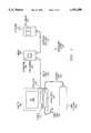
- FIG. 1is a block diagram of a preferred embodiment of the present invention having a monitor, a camera, an event recorder, and an activation unit;
- FIG. 2is a block diagram of an alternate preferred embodiment of the present invention having the camera and the activation unit incorporated into a single unit and
- FIG. 3is a block diagram of another alternate preferred embodiment of the present invention having an activation unit which uses a trickle charged battery for powering auxiliary devices.
- the surveillance system 100generally comprises a monitor 200, a camera 300 connected to the monitor 200 by a cable 310, an event recorder 400 connected to the monitor 200 by a cable 410, and an activation unit 500 connected to the camera 300 by a cable 510.
- the monitor 200can be a standard closed circuit television (CCTV) monitor for security purposes such as the Exxis monitor Model KM-091Co
- the camera 300is a standard CCTV camera such as the Exxis camera Model PSC-1.
- the event monitoris any type of recording device suitable for recording audio and video signals, for example, a VCR real time or event recorder, such as the CCTV Source Model UL200 VCR .
- the activation unit 500can be any standard activation unit for a security system, such as the Exxis passive infrared motion detector Model KO-800.
- the monitor 200receives power through a power cable 210.
- a power supply 220 in the monitor 200converts the power from the power cable 220 into a form useable by the camera 300 and the activation unit 500.
- the camera 300receives the converted power from the power supply 220 through the camera cable 310.
- the activation unit 500receives this converted power from the camera 300 through the activation unit cable 510.
- the power supply 220also converts power from the power cable 210 into a form useable by the event recorder 400, and transmits that converted power to the event recorder 400 through recorder cable 410.
- the camera 300has a video camera 320 and a microphone 330 for generating video and audio signals of an area under surveillance by the surveillance system 100. These video and audio signals are sent to the monitor 200 through camera cable 310.
- a cathode ray tube (CRT) 260 in the monitor 200uses the video signals to display the image received by the video camera 320 in the camera 300
- a speaker 270 in the monitor 200uses the audio signals to project the noises received by the microphone 330 in the camera 300.
- CTRcathode ray tube
- the activation unit 500contains a sensor, such as a passive infrared (PIR) sensor 520, for detecting a condition for which the surveillance system 100 requires activation.
- a sensorsuch as a passive infrared (PIR) sensor 520
- PIRpassive infrared
- the present embodimentillustrates the use of the PIR sensor 520, other sensors, such as glass break detectors, motion detectors, open circuit sensors, closed circuit sensors, or the like, can be used in place thereof.
- the PIR sensor 520senses a condition for activating the surveillance system 100
- the activation unit 500sends an activation signal to the camera 300 through the activation unit cable 510.
- the camera 300sends the activation signal to the monitor 200 through the camera cable 310.
- a processor 250 in the monitor 200receives the activation signal from camera cable 310.
- the processor 250Upon receiving the activation signal, the processor 250 sends the video signals and audio signals from the camera 300 to the event recorder 400, and a command for the event recorder 400 to record the video and audio signals generated by the camera 300. If the sensor in the activation unit 500 is a sensor receiving a transient condition, such as the breaking of glass, the processor 250 can determine a preset time period for which the event recorder 400 is to record the video and audio signals generated by the camera 300. Although the processor 250 is illustrated herein as being a part of the monitor 200, the processor 250 can be a separate component from the monitor 200, or a part of any other component in the surveillance system 100, such as the event recorder 400. Also, although FIG.
- FIG. 1illustrates the video and audio signals from the camera 300 as passing through the processor 250 before reaching the event recorder 400 or the CRT 260 and the speaker 270 of the monitor 200, the video and audio signals could be routed directly to the event recorder 400 or the CRT 260 and the speaker 270 without requiring those signals to pass through the processor 250.
- the surveillance system 100 of FIG. 1is illustrated with only one camera 300, it is possible to have a plurality of cameras 300 connected to the monitor, with each camera 300 connected to an activation unit 500.
- the processor 250sequentially displays for a short period of time the video and audio signals from each of the cameras 300.
- the processor 250Upon receiving an activation signal, displays only the video and audio signals from the camera 300 attached to the activation unit 500 sending the activation signal.
- the processor 250activates the event recorder 400 to record the video and audio signals generated by the camera 300 and sent to the event recorder 400 by the processor 250.
- the surveillance system 110generally comprises the monitor 200, a camera/activation unit 600 connected to the monitor 200 by a cable 610, and the event recorder 400 connected to the monitor 200 by the cable 410
- the monitor 200has a power cable 210 for receiving electrical power.
- a power supply 220 in the monitor 200converts the power from the power cable 210 into a form useable by the camera/activation unit 600.
- the converted poweris supplied from the power supply 220 to the camera/activation unit 600 through the camera/activation cable 610.
- the power supply 220also converts power from the power cable 210 into a form useable by the event recorder 400, and transmits that converted power to the event recorder 400 through the recorder cable 410.
- the camera/activation unit 600has a video camera 620 and a microphone 630 for generating video and audio signals of an area under surveillance by the surveillance system 110. These video and audio signals are sent to the monitor 200 through the camera/activation cable 610.
- a cathode ray tube (CRT) 260 in the monitor 200uses the video signals to display the image received by the video camera 620 in the camera/activation unit 600.
- a speaker 270 in the monitor 200uses the audio signals to project the noises received by the microphone 630 in the camera/activation unit 600.
- CTRcathode ray tube
- the camera/activation unit 600also contains a sensor, such as a PIR sensor 630, for detecting a condition for which the surveillance system 110 requires activation.
- a sensorsuch as a PIR sensor 630
- other sensorssuch as glass break detectors, motion detectors, open circuit sensors, closed circuit sensors, or the like, can be used in place thereof.
- the camera/activation unit 600sends an activation signal through the camera/activation cable 610 to the processor 250 in the monitor 200.
- the processorUpon receiving the activation signal, the processor sends the video and audio signals from the camera/activation unit 600 to the event recorder 400, and a command for the event recorder 400 to record the video and audio signals generated by the camera/activation unit 600.
- the processor 250can determine a preset time for which the event recorder is to record the video and audio signals generated by the camera/activation unit 600.
- the processor 250is illustrated herein as being part of the monitor 200, the processor can be a separate component from the monitor 200, or a part of any other component in the surveillance system 110, such as the event recorder 400. Also, although FIG.
- FIG. 2illustrates the video and audio signals from the camera/activation unit 600 as passing through the processor 250 before reaching the event recorder 400 or the CRT 260 and the speaker 270 of the monitor 200, the video and audio signals could be routed directly to the event recorder 400 or the CRT 260 and the speaker 270 without requiring those signals to pass through the processor 250.
- the surveillance system 110 in FIG. 2can have a plurality of camera/activation units 600 connected to the monitor 200.
- the processor 250sequentially displays for a short period of time the video and audio signals from each of the plurality of camera/activation units 600.
- the processor 250Upon receiving an activation signal from a particular camera/activation unit 600, the processor 250 causes the video and audio signals of the camera/activation unit 600 sending the activation signal, to be displayed on the monitor 200 continuously.
- the processor 250sends a command through the recorder cable 410 for the event recorder to record the video and audio signals, which are also sent to the event recorder 400 through the recorder cable 410 of the camera/activation unit 600 sending the activation signal.
- FIG. 3there is shown a block diagram of another alternate preferred embodiment of the present invention, illustrated as a surveillance system 120.
- the surveillance system 120has the monitor 200, the camera 300 connected to the monitor 200 by the cable 310, an event recorder 400 connected to the monitor 200 by the recorder cable 410, and an activation unit 700 connected to the camera 300 by an activation unit cable 710.
- the monitor 200receives power through the power cable 210.
- a power supply 220 in the monitor 200converts the power from the power cable 210 to a form for use by the camera 300 and the activation unit 700.
- the camera 300receives this converted power from the power supply 220 through the camera cable 310.
- the activation unit 700receives the power converted by the power supply 200 from the camera 300 through the activation unit cable 710.
- the activation unit 700uses the converted power to trickle charge a battery 730 and to power the PIR sensor 720.
- the power supply 220 of the monitor 200also converts the power from the power cable 210 for use by the event recorder 400 and transmits that converted power to the event recorder 400 through recorder cable 410.
- the camera 300 of surveillance system 120 in FIG. 3has a video camera 320 and a microphone 330 for generating video and audio signals of the area under surveillance by the surveillance system 120. These video and audio signals are sent to the monitor 200 through cable 310. The monitor 200 then displays the video images from video camera 320 on the CTR 260, and projects the noises received by the microphone 330 over the speaker 270.
- the activation unit 700contains a sensor, such as a PIR sensor 720, for detecting a condition for which the surveillance system 120 requires activation.
- a sensorsuch as a PIR sensor 720
- other sensorssuch as glass break detectors, motion detectors, open circuit detectors, closed circuit detectors, or the like, can be used in place thereof.
- the PIR sensor 720senses a condition for activating the surveillance system 120
- the activation unit 700sends an activation signal through the activation unit cable 710, the camera 300, and the camera cable 310 to a processor 250 in the monitor 200.
- the processor 250Upon receiving the activation signal, the processor 250 sends the video and audio signals from the camera 300 to the event recorder 400, and a command for the event recorder to record the video and audio signals generated by the camera 300. If the sensor in the activation unit 700 is a sensor receiving a transient condition, such as the breaking of glass, the processor 250 can determine a preset time period for which the event recorder is to record the video and audio signals generated by the camera 300. Although the processor 250 is illustrated herein as being part of the monitor 200, the processor 250 can be a separate component from the monitor 200, or a part of any other component in the surveillance system 120, such as the event recorder 400. Also, although FIG.
- FIG 3illustrates the video and audio signals from the camera 300 as passing through the processor 250 before reaching the event recorder 400 or the CRT 260 and the speaker 270 of the monitor 200, the video and audio signals could be routed directly to the event recorder 400 or the CRT 260 and the speaker 270 without requiring those signals to pass through the processor 250.
- the activation unit 700Upon sensing by the PIR sensor 720 of a condition for which the surveillance system 120 required to activate, the activation unit 700 activates an auxiliary device, such as the light 740. Because the power demand of an auxiliary device, such as the light 740, is greater than the power provided to the activation unit 700 through the activation unit cable 710, a battery 730 supplies the power to operate the auxiliary unit for a predetermined period of the condition to be recorded.
- auxiliary equipmentsuch as sirens, horns, or the like, can be used with the battery 730 on the activation unit 700.
- the surveillance system 120 in FIG. 3it is possible for the surveillance system 120 in FIG. 3 to have a plurality of cameras 300 connected to the monitor 200, with each camera 300 connected to an activation unit 700.
- the processor 250would sequentially display for a short period of time the video and audio signals from each of the cameras 300.
- the processor 250Upon receiving an activation signal from the activation unit 700, the processor 250 causes the monitor 200 to display only the video and audio signals from the camera 300 sending the activation signal from its associated activation unit 700. Also upon receiving an activation signal, the processor 250 activates the event recorder 400 to record the audio and video signals generated by the camera 300 and sent to the event recorder 400 by the processor 250.
Landscapes
- Engineering & Computer Science (AREA)
- Multimedia (AREA)
- Physics & Mathematics (AREA)
- General Physics & Mathematics (AREA)
- Signal Processing (AREA)
- Closed-Circuit Television Systems (AREA)
Abstract
Description
Claims (10)
Priority Applications (1)
| Application Number | Priority Date | Filing Date | Title |
|---|---|---|---|
| US08/189,022US5495288A (en) | 1994-01-28 | 1994-01-28 | Remote activated surveillance system |
Applications Claiming Priority (1)
| Application Number | Priority Date | Filing Date | Title |
|---|---|---|---|
| US08/189,022US5495288A (en) | 1994-01-28 | 1994-01-28 | Remote activated surveillance system |
Publications (1)
| Publication Number | Publication Date |
|---|---|
| US5495288Atrue US5495288A (en) | 1996-02-27 |
Family
ID=22695579
Family Applications (1)
| Application Number | Title | Priority Date | Filing Date |
|---|---|---|---|
| US08/189,022Expired - LifetimeUS5495288A (en) | 1994-01-28 | 1994-01-28 | Remote activated surveillance system |
Country Status (1)
| Country | Link |
|---|---|
| US (1) | US5495288A (en) |
Cited By (45)
| Publication number | Priority date | Publication date | Assignee | Title |
|---|---|---|---|---|
| GB2309133A (en)* | 1996-01-11 | 1997-07-16 | Richad Thomas Fortescue | Video surveillance system including video recorder timing control device |
| US5654750A (en)* | 1995-02-23 | 1997-08-05 | Videorec Technologies, Inc. | Automatic recording system |
| DE19710727A1 (en)* | 1997-03-14 | 1998-09-17 | Sick Ag | Monitoring device |
| US5819124A (en)* | 1994-09-13 | 1998-10-06 | Timothy Laurie Somner | Security system |
| US5825413A (en)* | 1995-11-01 | 1998-10-20 | Thomson Consumer Electronics, Inc. | Infrared surveillance system with controlled video recording |
| WO2002011449A1 (en)* | 2000-08-01 | 2002-02-07 | Koninklijke Philips Electronics N.V. | Representative presence for sensor-based security systems and other applications |
| US20030004913A1 (en)* | 2001-07-02 | 2003-01-02 | Koninklijke Philips Electronics N.V. | Vision-based method and apparatus for detecting an event requiring assistance or documentation |
| US6570499B2 (en) | 2001-02-20 | 2003-05-27 | Victor Kaganer | Household security and surveillance system utilizing a video recorder |
| US20030164877A1 (en)* | 2000-06-30 | 2003-09-04 | Nobuo Murai | Remote monitoring method and monitor control server |
| US20040021778A1 (en)* | 2002-08-05 | 2004-02-05 | Oldani Jerome L. | Security system with remote access and control |
| US20040075547A1 (en)* | 2002-02-12 | 2004-04-22 | Vojtech George L | Commandable covert surveillance system |
| US20040157612A1 (en)* | 1997-04-25 | 2004-08-12 | Minerva Industries, Inc. | Mobile communication and stethoscope system |
| US6819239B2 (en) | 2002-08-20 | 2004-11-16 | Victoria J. Bingham | Lighting security system |
| US20050117052A1 (en)* | 2003-12-02 | 2005-06-02 | Wilife Inc. | Network camera mounting system |
| US20050120128A1 (en)* | 2003-12-02 | 2005-06-02 | Wilife, Inc. | Method and system of bandwidth management for streaming data |
| US20050165612A1 (en)* | 2000-04-19 | 2005-07-28 | Van Rysselberghe Pierre C. | Security systems for delivering goods and services |
| US6954859B1 (en)* | 1999-10-08 | 2005-10-11 | Axcess, Inc. | Networked digital security system and methods |
| US20050252980A1 (en)* | 1997-04-25 | 2005-11-17 | Minerva Industries, Inc. | Mobile entertainment and communication device |
| US20060098091A1 (en)* | 2004-11-05 | 2006-05-11 | Samsung Electronics Co., Ltd. | Surveillance system for remotely controlling camera through monitor and method thereof |
| US20060171453A1 (en)* | 2005-01-04 | 2006-08-03 | Rohlfing Thomas R | Video surveillance system |
| US20060198611A1 (en)* | 2005-03-03 | 2006-09-07 | Jung-Jae Park | Digital video recording method in an audio detection mode |
| US20060255931A1 (en)* | 2005-05-12 | 2006-11-16 | Hartsfield Andrew J | Modular design for a security system |
| WO2007060472A1 (en)* | 2005-11-28 | 2007-05-31 | Stephen Guy Lacey Jackson | An optical image recording device |
| US20070132597A1 (en)* | 2005-12-09 | 2007-06-14 | Valence Broadband, Inc. | Methods and systems for monitoring patient support exiting and initiating response |
| US20070162304A1 (en)* | 2005-12-09 | 2007-07-12 | Valence Broadband, Inc. | Methods and systems for monitoring quality and performance at a healthcare facility |
| US20070288263A1 (en)* | 2005-12-09 | 2007-12-13 | Valence Broadband, Inc. | Methods and systems for monitoring quality and performance at a healthcare facility |
| US20080015903A1 (en)* | 2005-12-09 | 2008-01-17 | Valence Broadband, Inc. | Methods for refining patient, staff and visitor profiles used in monitoring quality and performance at a healthcare facility |
| US20080021731A1 (en)* | 2005-12-09 | 2008-01-24 | Valence Broadband, Inc. | Methods and systems for monitoring patient support exiting and initiating response |
| US20080033752A1 (en)* | 2006-08-04 | 2008-02-07 | Valence Broadband, Inc. | Methods and systems for monitoring staff/patient contacts and ratios |
| US20090044332A1 (en)* | 2007-08-13 | 2009-02-19 | Valence Broadband, Inc. | Height adjustable patient support platforms |
| US20090044334A1 (en)* | 2007-08-13 | 2009-02-19 | Valence Broadband, Inc. | Automatically adjusting patient platform support height in response to patient related events |
| US20090119843A1 (en)* | 2007-11-12 | 2009-05-14 | Valence Broadband, Inc. | Monitoring patient support exiting and initiating response |
| US20100118143A1 (en)* | 2008-11-09 | 2010-05-13 | Haim Amir | Extended life video camera system and method |
| US7786874B2 (en) | 2005-12-09 | 2010-08-31 | Samarion, Inc. | Methods for refining patient, staff and visitor profiles used in monitoring quality and performance at a healthcare facility |
| US20100316212A1 (en)* | 2003-09-15 | 2010-12-16 | Accenture Global Services Gmbh | Remote media call center |
| US20110216191A1 (en)* | 2010-03-02 | 2011-09-08 | Davis Alan W | System and methods for efficient installation of surveillance systems and focus tool system |
| US20130201025A1 (en)* | 2012-02-07 | 2013-08-08 | Arunkumar Kamalakannan | Method of Monitoring a Gas Leakage Incident |
| US8620625B2 (en) | 2010-07-30 | 2013-12-31 | Hill-Rom Services, Inc. | Above bed sensor |
| US8907287B2 (en) | 2010-12-01 | 2014-12-09 | Hill-Rom Services, Inc. | Patient monitoring system |
| EP2376207B1 (en)* | 2008-12-09 | 2015-08-12 | Koninklijke Philips N.V. | Method and system for generating data for controlling a system for rendering at least one signal |
| JP2016019187A (en)* | 2014-07-09 | 2016-02-01 | 住友電気工業株式会社 | Measuring device |
| US9295390B2 (en) | 2012-03-02 | 2016-03-29 | Hill-Rom Services, Inc. | Facial recognition based monitoring systems and methods |
| US9311804B2 (en) | 2014-04-11 | 2016-04-12 | Hill-Rom Services, Inc. | Patient-need prediction system |
| US10192418B1 (en) | 2018-06-11 | 2019-01-29 | Geoffrey M. Kern | System and method for perimeter security |
| US20210099635A1 (en)* | 2019-09-26 | 2021-04-01 | Williamsrdm, Inc. | Externally attachable device triggering system and method of use |
Citations (4)
| Publication number | Priority date | Publication date | Assignee | Title |
|---|---|---|---|---|
| US3699250A (en)* | 1965-01-11 | 1972-10-17 | Bunting Sterisystems Inc | Process and signal distributing system and apparatus used therein |
| US4766491A (en)* | 1986-05-30 | 1988-08-23 | Sony Corporation | Adaptor for a video monitoring system |
| US4969046A (en)* | 1988-06-03 | 1990-11-06 | Sony Corporation | Television monitor system |
| US5428388A (en)* | 1992-06-15 | 1995-06-27 | Richard von Bauer | Video doorbell system |
- 1994
- 1994-01-28USUS08/189,022patent/US5495288A/ennot_activeExpired - Lifetime
Patent Citations (4)
| Publication number | Priority date | Publication date | Assignee | Title |
|---|---|---|---|---|
| US3699250A (en)* | 1965-01-11 | 1972-10-17 | Bunting Sterisystems Inc | Process and signal distributing system and apparatus used therein |
| US4766491A (en)* | 1986-05-30 | 1988-08-23 | Sony Corporation | Adaptor for a video monitoring system |
| US4969046A (en)* | 1988-06-03 | 1990-11-06 | Sony Corporation | Television monitor system |
| US5428388A (en)* | 1992-06-15 | 1995-06-27 | Richard von Bauer | Video doorbell system |
Cited By (64)
| Publication number | Priority date | Publication date | Assignee | Title |
|---|---|---|---|---|
| US5819124A (en)* | 1994-09-13 | 1998-10-06 | Timothy Laurie Somner | Security system |
| US5654750A (en)* | 1995-02-23 | 1997-08-05 | Videorec Technologies, Inc. | Automatic recording system |
| US5825413A (en)* | 1995-11-01 | 1998-10-20 | Thomson Consumer Electronics, Inc. | Infrared surveillance system with controlled video recording |
| GB2309133A (en)* | 1996-01-11 | 1997-07-16 | Richad Thomas Fortescue | Video surveillance system including video recorder timing control device |
| DE19710727A1 (en)* | 1997-03-14 | 1998-09-17 | Sick Ag | Monitoring device |
| US20050252980A1 (en)* | 1997-04-25 | 2005-11-17 | Minerva Industries, Inc. | Mobile entertainment and communication device |
| US20060226242A2 (en)* | 1997-04-25 | 2006-10-12 | Kim Ki I | Mobile Entertainment and Communication Device |
| US20050263604A1 (en)* | 1997-04-25 | 2005-12-01 | Minerva Industries, Inc. | Mobile entertainment and communication device |
| US20040157612A1 (en)* | 1997-04-25 | 2004-08-12 | Minerva Industries, Inc. | Mobile communication and stethoscope system |
| US20090213264A1 (en)* | 1997-04-25 | 2009-08-27 | Ki Il Kim | Mobile entertainment and communication device |
| US7952609B2 (en) | 1999-10-08 | 2011-05-31 | Axcess International, Inc. | Networked digital security system and methods |
| US6954859B1 (en)* | 1999-10-08 | 2005-10-11 | Axcess, Inc. | Networked digital security system and methods |
| US20090179735A1 (en)* | 2000-04-19 | 2009-07-16 | Van Rysselberghe Pierre C | Security systems |
| US20050165612A1 (en)* | 2000-04-19 | 2005-07-28 | Van Rysselberghe Pierre C. | Security systems for delivering goods and services |
| US20030164877A1 (en)* | 2000-06-30 | 2003-09-04 | Nobuo Murai | Remote monitoring method and monitor control server |
| US7231654B2 (en)* | 2000-06-30 | 2007-06-12 | Japan Network Service Co., Ltd. | Remote monitoring method and monitor control server |
| WO2002011449A1 (en)* | 2000-08-01 | 2002-02-07 | Koninklijke Philips Electronics N.V. | Representative presence for sensor-based security systems and other applications |
| US6570499B2 (en) | 2001-02-20 | 2003-05-27 | Victor Kaganer | Household security and surveillance system utilizing a video recorder |
| US20030004913A1 (en)* | 2001-07-02 | 2003-01-02 | Koninklijke Philips Electronics N.V. | Vision-based method and apparatus for detecting an event requiring assistance or documentation |
| US20040075547A1 (en)* | 2002-02-12 | 2004-04-22 | Vojtech George L | Commandable covert surveillance system |
| US20040021778A1 (en)* | 2002-08-05 | 2004-02-05 | Oldani Jerome L. | Security system with remote access and control |
| US6819239B2 (en) | 2002-08-20 | 2004-11-16 | Victoria J. Bingham | Lighting security system |
| US8515050B2 (en)* | 2003-09-15 | 2013-08-20 | Accenture Global Services Limited | Remote media call center |
| US20100316212A1 (en)* | 2003-09-15 | 2010-12-16 | Accenture Global Services Gmbh | Remote media call center |
| US7599002B2 (en) | 2003-12-02 | 2009-10-06 | Logitech Europe S.A. | Network camera mounting system |
| US20050120128A1 (en)* | 2003-12-02 | 2005-06-02 | Wilife, Inc. | Method and system of bandwidth management for streaming data |
| US20050117052A1 (en)* | 2003-12-02 | 2005-06-02 | Wilife Inc. | Network camera mounting system |
| US20060098091A1 (en)* | 2004-11-05 | 2006-05-11 | Samsung Electronics Co., Ltd. | Surveillance system for remotely controlling camera through monitor and method thereof |
| WO2006074328A3 (en)* | 2005-01-04 | 2009-04-16 | Wilife Inc | Video surveillance system |
| US20060171453A1 (en)* | 2005-01-04 | 2006-08-03 | Rohlfing Thomas R | Video surveillance system |
| US8086088B2 (en)* | 2005-03-03 | 2011-12-27 | Sam Myung Co., Ltd. | Digital video recording method in an audio detection mode |
| US20060198611A1 (en)* | 2005-03-03 | 2006-09-07 | Jung-Jae Park | Digital video recording method in an audio detection mode |
| US20060255931A1 (en)* | 2005-05-12 | 2006-11-16 | Hartsfield Andrew J | Modular design for a security system |
| WO2007060472A1 (en)* | 2005-11-28 | 2007-05-31 | Stephen Guy Lacey Jackson | An optical image recording device |
| US20070132597A1 (en)* | 2005-12-09 | 2007-06-14 | Valence Broadband, Inc. | Methods and systems for monitoring patient support exiting and initiating response |
| US20080021731A1 (en)* | 2005-12-09 | 2008-01-24 | Valence Broadband, Inc. | Methods and systems for monitoring patient support exiting and initiating response |
| US7911348B2 (en) | 2005-12-09 | 2011-03-22 | Bee Cave, LLC. | Methods for refining patient, staff and visitor profiles used in monitoring quality and performance at a healthcare facility |
| US20080015903A1 (en)* | 2005-12-09 | 2008-01-17 | Valence Broadband, Inc. | Methods for refining patient, staff and visitor profiles used in monitoring quality and performance at a healthcare facility |
| US20070288263A1 (en)* | 2005-12-09 | 2007-12-13 | Valence Broadband, Inc. | Methods and systems for monitoring quality and performance at a healthcare facility |
| US20070162304A1 (en)* | 2005-12-09 | 2007-07-12 | Valence Broadband, Inc. | Methods and systems for monitoring quality and performance at a healthcare facility |
| US7761310B2 (en) | 2005-12-09 | 2010-07-20 | Samarion, Inc. | Methods and systems for monitoring quality and performance at a healthcare facility |
| US7786874B2 (en) | 2005-12-09 | 2010-08-31 | Samarion, Inc. | Methods for refining patient, staff and visitor profiles used in monitoring quality and performance at a healthcare facility |
| US20080033752A1 (en)* | 2006-08-04 | 2008-02-07 | Valence Broadband, Inc. | Methods and systems for monitoring staff/patient contacts and ratios |
| US20090044334A1 (en)* | 2007-08-13 | 2009-02-19 | Valence Broadband, Inc. | Automatically adjusting patient platform support height in response to patient related events |
| US20090044332A1 (en)* | 2007-08-13 | 2009-02-19 | Valence Broadband, Inc. | Height adjustable patient support platforms |
| US20090119843A1 (en)* | 2007-11-12 | 2009-05-14 | Valence Broadband, Inc. | Monitoring patient support exiting and initiating response |
| US7987069B2 (en) | 2007-11-12 | 2011-07-26 | Bee Cave, Llc | Monitoring patient support exiting and initiating response |
| US20100118143A1 (en)* | 2008-11-09 | 2010-05-13 | Haim Amir | Extended life video camera system and method |
| US8547433B2 (en)* | 2008-11-09 | 2013-10-01 | Haim Amir | Extended life video camera system and method |
| EP2376207B1 (en)* | 2008-12-09 | 2015-08-12 | Koninklijke Philips N.V. | Method and system for generating data for controlling a system for rendering at least one signal |
| US20110216191A1 (en)* | 2010-03-02 | 2011-09-08 | Davis Alan W | System and methods for efficient installation of surveillance systems and focus tool system |
| US8620625B2 (en) | 2010-07-30 | 2013-12-31 | Hill-Rom Services, Inc. | Above bed sensor |
| US8907287B2 (en) | 2010-12-01 | 2014-12-09 | Hill-Rom Services, Inc. | Patient monitoring system |
| US20150141838A1 (en)* | 2010-12-01 | 2015-05-21 | Hill-Rom Services, Inc. | Patient monitoring system |
| US9301689B2 (en)* | 2010-12-01 | 2016-04-05 | Hill-Rom Services, Inc. | Patient monitoring system |
| US20130201025A1 (en)* | 2012-02-07 | 2013-08-08 | Arunkumar Kamalakannan | Method of Monitoring a Gas Leakage Incident |
| US9295390B2 (en) | 2012-03-02 | 2016-03-29 | Hill-Rom Services, Inc. | Facial recognition based monitoring systems and methods |
| US9311804B2 (en) | 2014-04-11 | 2016-04-12 | Hill-Rom Services, Inc. | Patient-need prediction system |
| US9763576B2 (en) | 2014-04-11 | 2017-09-19 | Hill-Rom Services, Inc. | Patient-need prediction system |
| US10172522B2 (en) | 2014-04-11 | 2019-01-08 | Hill-Rom Services, Inc. | Patient-need prediction system |
| JP2016019187A (en)* | 2014-07-09 | 2016-02-01 | 住友電気工業株式会社 | Measuring device |
| US10192418B1 (en) | 2018-06-11 | 2019-01-29 | Geoffrey M. Kern | System and method for perimeter security |
| US20210099635A1 (en)* | 2019-09-26 | 2021-04-01 | Williamsrdm, Inc. | Externally attachable device triggering system and method of use |
| US12047676B2 (en)* | 2019-09-26 | 2024-07-23 | Williamsrdm, Inc. | Externally attachable device triggering system and method of use |
Similar Documents
| Publication | Publication Date | Title |
|---|---|---|
| US5495288A (en) | Remote activated surveillance system | |
| US5657076A (en) | Security and surveillance system | |
| US5448290A (en) | Video security system with motion sensor override, wireless interconnection, and mobile cameras | |
| US7015943B2 (en) | Premises entry security system | |
| US20110274421A1 (en) | Remote-control door viewer surveillance system | |
| US5382943A (en) | Remote monitoring unit | |
| US20080239072A1 (en) | Door monitor with a portable storage medium | |
| US20070019077A1 (en) | Portable surveillance camera and personal surveillance system using the same | |
| US20030095185A1 (en) | Electronic door viewer and method of use | |
| CA2115179C (en) | System for the monitoring and detection of heat sources in open areas | |
| US20040085205A1 (en) | Monitor system with video and audio transmission actuated by doorbell actuator | |
| US20090027498A1 (en) | Security clock device and system | |
| EP2385703A1 (en) | Remote-control door viewer surveillance system | |
| KR101507978B1 (en) | Versatile closed circuit television security system | |
| US20090284600A1 (en) | Remote-control door viewer surveillance system | |
| WO2000070796A8 (en) | Remote control incorporating self test capability | |
| US7372362B2 (en) | Security alarm system having minimal wiring to CCTV camera | |
| GB2445596A (en) | Remote control door viewer surveillance system | |
| EP1751723B1 (en) | Surveillance system and method | |
| EP1837838A1 (en) | Security alarm system having minimal wiring to CCTV camera | |
| JP2874239B2 (en) | Security information notification device for apartment houses | |
| KR20160010633A (en) | Invader Monitoring and Alarm System using Thermal Image Fusion Camera | |
| US20050246418A1 (en) | Server and display device | |
| JPH07222070A (en) | Earthquake information notification system | |
| JPH01106685A (en) | AV system remote control method |
Legal Events
| Date | Code | Title | Description |
|---|---|---|---|
| AS | Assignment | Owner name:ULTRAK, INC., TEXAS Free format text:ASSIGNMENT OF ASSIGNORS INTEREST;ASSIGNOR:BROADY, GEORGE K.;REEL/FRAME:007004/0175 Effective date:19940406 Owner name:ULTRAK, INC., TEXAS Free format text:ASSIGNMENT OF ASSIGNORS INTEREST;ASSIGNOR:NICHOLS, RONALD L.;REEL/FRAME:007004/0179 Effective date:19940405 Owner name:ULTRAK, INC., TEXAS Free format text:ASSIGNMENT OF ASSIGNORS INTEREST;ASSIGNOR:PRITCHETT, JAMES D.;REEL/FRAME:007004/0183 Effective date:19940324 | |
| STCF | Information on status: patent grant | Free format text:PATENTED CASE | |
| CC | Certificate of correction | ||
| FEPP | Fee payment procedure | Free format text:PAT HLDR NO LONGER CLAIMS SMALL ENT STAT AS SMALL BUSINESS (ORIGINAL EVENT CODE: LSM2); ENTITY STATUS OF PATENT OWNER: LARGE ENTITY | |
| AS | Assignment | Owner name:BANK ONE, TEXAS, N.A., TEXAS Free format text:SECURITY AGREEMENT;ASSIGNOR:ULTRAK, INC.;REEL/FRAME:009764/0596 Effective date:19990216 | |
| FPAY | Fee payment | Year of fee payment:4 | |
| AS | Assignment | Owner name:AMERICAN NATIONAL BANK AND TRUST COMPANY OF CHICAG Free format text:SECURITY AGREEMENT;ASSIGNOR:ULTRAK, INC.;REEL/FRAME:010731/0977 Effective date:20000322 | |
| AS | Assignment | Owner name:ULTRAK, INC., TEXAS Free format text:TERMINATION OF SECURITY INTEREST;ASSIGNOR:AMERICAN NATIONAL BANK AND TRUST COMPANY OF CHICAGO;REEL/FRAME:012865/0180 Effective date:20000517 | |
| AS | Assignment | Owner name:THE FROST NATIONAL BANK, TEXAS Free format text:SECURITY AGREEMENT;ASSIGNOR:ULTRAK, INC.;REEL/FRAME:012875/0001 Effective date:20020419 | |
| AS | Assignment | Owner name:ULTRAK, INC., TEXAS Free format text:RELEASE SECURITY AGREEMENT;ASSIGNOR:FROST NATIONAL BANK, THE;REEL/FRAME:013323/0142 Effective date:20021220 | |
| FPAY | Fee payment | Year of fee payment:8 | |
| AS | Assignment | Owner name:HONEYWELL INTERNATIONAL, INC., NEW JERSEY Free format text:ASSIGNMENT OF ASSIGNORS INTEREST;ASSIGNOR:ULTRAK, INC.;REEL/FRAME:015108/0828 Effective date:20021220 | |
| FPAY | Fee payment | Year of fee payment:12 |