US5495163A - Control for a brushless generator operable in generating and starting modes - Google Patents
Control for a brushless generator operable in generating and starting modesDownload PDFInfo
- Publication number
- US5495163A US5495163AUS08/061,496US6149693AUS5495163AUS 5495163 AUS5495163 AUS 5495163AUS 6149693 AUS6149693 AUS 6149693AUS 5495163 AUS5495163 AUS 5495163A
- Authority
- US
- United States
- Prior art keywords
- signal
- pmg
- motive power
- phase windings
- power shaft
- Prior art date
- Legal status (The legal status is an assumption and is not a legal conclusion. Google has not performed a legal analysis and makes no representation as to the accuracy of the status listed.)
- Expired - Lifetime
Links
- 238000004804windingMethods0.000claimsabstractdescription79
- 238000000034methodMethods0.000claimsdescription21
- 230000001143conditioned effectEffects0.000claimsdescription2
- 230000003750conditioning effectEffects0.000claims1
- 238000010586diagramMethods0.000description7
- 230000001360synchronised effectEffects0.000description5
- 230000001419dependent effectEffects0.000description3
- 238000013459approachMethods0.000description2
- 238000012986modificationMethods0.000description2
- 230000004048modificationEffects0.000description2
- 239000007858starting materialSubstances0.000description2
- 230000005355Hall effectEffects0.000description1
- 230000001133accelerationEffects0.000description1
- 230000003044adaptive effectEffects0.000description1
- 239000004020conductorSubstances0.000description1
- 230000004907fluxEffects0.000description1
- 230000036039immunityEffects0.000description1
- 230000000977initiatory effectEffects0.000description1
- 230000003287optical effectEffects0.000description1
- 230000001105regulatory effectEffects0.000description1
- 230000003068static effectEffects0.000description1
Images


Classifications
- F—MECHANICAL ENGINEERING; LIGHTING; HEATING; WEAPONS; BLASTING
- F02—COMBUSTION ENGINES; HOT-GAS OR COMBUSTION-PRODUCT ENGINE PLANTS
- F02N—STARTING OF COMBUSTION ENGINES; STARTING AIDS FOR SUCH ENGINES, NOT OTHERWISE PROVIDED FOR
- F02N11/00—Starting of engines by means of electric motors
- F02N11/04—Starting of engines by means of electric motors the motors being associated with current generators
- H—ELECTRICITY
- H02—GENERATION; CONVERSION OR DISTRIBUTION OF ELECTRIC POWER
- H02P—CONTROL OR REGULATION OF ELECTRIC MOTORS, ELECTRIC GENERATORS OR DYNAMO-ELECTRIC CONVERTERS; CONTROLLING TRANSFORMERS, REACTORS OR CHOKE COILS
- H02P9/00—Arrangements for controlling electric generators for the purpose of obtaining a desired output
- H02P9/02—Details of the control
- H—ELECTRICITY
- H02—GENERATION; CONVERSION OR DISTRIBUTION OF ELECTRIC POWER
- H02P—CONTROL OR REGULATION OF ELECTRIC MOTORS, ELECTRIC GENERATORS OR DYNAMO-ELECTRIC CONVERTERS; CONTROLLING TRANSFORMERS, REACTORS OR CHOKE COILS
- H02P2101/00—Special adaptation of control arrangements for generators
- H02P2101/30—Special adaptation of control arrangements for generators for aircraft
- H—ELECTRICITY
- H02—GENERATION; CONVERSION OR DISTRIBUTION OF ELECTRIC POWER
- H02P—CONTROL OR REGULATION OF ELECTRIC MOTORS, ELECTRIC GENERATORS OR DYNAMO-ELECTRIC CONVERTERS; CONTROLLING TRANSFORMERS, REACTORS OR CHOKE COILS
- H02P9/00—Arrangements for controlling electric generators for the purpose of obtaining a desired output
Definitions
- the present inventionrelates generally to electromagnetic machines, and more particularly to a detector for detecting the rotor position of a brushless generator and a control system incorporating such a detector.
- An auxiliary power unit (APU) systemis often provided on an aircraft and is operable to provide auxiliary and/or emergency power to one or more aircraft loads.
- APUauxiliary power unit
- a dedicated starter motoris operated during a starting sequence to bring a gas turbine engine up to self-sustaining speed, following which the engine is accelerated to operating speed.
- a brushless, synchronous generatoris coupled to and driven by the gas turbine engine during operation in a starting mode whereupon the generator develops electrical power.
- an electromagnetic machinemay be operated as a motor to convert electrical power into motive power.
- a source of motive poweris required for engine starting, such as in an APU system
- This capabilityis particularly advantageous in aircraft applications where size and weight must be held to a minimum.
- variable-speed, constant-frequency (VSCF) power generating systema brushless, three-phase synchronous generator operates in the generating mode to convert variable-speed motive power supplied by a prime mover into variable-frequency AC power.
- the variable-frequency poweris rectified and provided over a DC link to a controllable static inverter.
- the inverteris operated to produce constant-frequency AC power, which is then supplied over a load bus to one or more loads.
- the generator of such a VSCF systemis operated as a motor in the starting mode to convert electrical power supplied by an external AC power source into motive power which is provided to the prime mover to bring it up to self-sustaining speed.
- a brushless, synchronous generatorincluding a permanent magnet generator (PMG), an exciter portion and a main generator portion mounted on a common shaft, it has been known to provide power at a controlled voltage and frequency to the armature windings of the main generator portion and to provide field current to the main generator portion field windings via the exciter portion so that the motive power may be developed.
- PMGpermanent magnet generator
- the direct methodcan be used to directly measure phase back EMF voltage only when the phase winding is not energized by the inverter connected thereto and when the winding is not short circuited either by closed switches in the inverter or by conducting flyback diodes in the inverter. Such conditions can be realized when a 120 degree commutation algorithm is utilized. In this case, a voltage reading is taken after a short delay following switching of the phase winding off to ensure complete current decay by the free-willing diodes.
- This direct techniqueis described in a paper entitled "Microcomputer Control for Sensorless Brushless Motor" by E. Iizuka et al., IEEE Transactions on Industry Application, Vol. IA-21, No. 4, May/June 1985.
- the indirect methodis based on estimating the back EMF from the motive terminal voltage and phase currents. This method is suitable for both 120 and 180 degree commutation algorithms.
- One technique that uses this methodis described in a paper entitled "Position--and--Velocity Sensorless Control for Brushless DC Motor Using an Adaptive Sliding Mode Observer" by Furuhashi et al., IEEE Transactions on Industrial Electronics, Vol. 39, No. 2, April 1992.
- a method of using a permanent magnet generator as a position sensor for motor/generator startis described in Stacey U.S. Pat. No. 5,140,245.
- a standard brushless generatoris equipped with a PMG which is used as an emergency electric power source and as a source of control power during a normal or generating mode of operation.
- the PMGdevelops a multi-phase output which is supplied to a high resolution phase-locked loop having a binary counter which develops an output signal representing shaft position.
- This methodis limited to the situation where the number of PMG rotor poles is equal to or less than the number of poles on the main generator portion rotor so that ambiguous position readings are avoided.
- a detector for detecting rotor position of brushless generatorutilizes inexpensive components and operates in a simple and effective manner.
- a detector for detecting rotor position of a brushless generator having a motive power shaft, a permanent magnet generator (PMG) having a set of armature phase windings at which a set of PMG phase outputs are produced and a main generator portion having a set of armature phase windings capable of receiving AC powerincludes means coupled to the PMG armature phase windings for deriving a number of interval pulses per revolution of the motive power shaft from the PMG phase outputs.
- PMGpermanent magnet generator
- Meansare coupled to the deriving means for measuring time periods between adjacent interval pulses and means are coupled to the measuring means and capable of responding to a parameter of the AC power delivered to one of the main generator portion armature phase windings for converting the measured time periods into an indication of the angular position of the motive power shaft.
- the measuring meanscomprises a counter which accumulates clock pulses during time periods between adjacent interval pulses. Also preferably, the counter is periodically reset a certain number of times during each revolution of the motive power shaft by the interval pulses.
- the converting meansincludes means for inverting a counter output signal developed by the counter to obtain an indication of the speed of the motive power shaft.
- the converting meansalso preferably includes an integrator coupled to the inverting means which develops the angular position indication.
- the integratoris preferably reset once per revolution of the motive power shaft by a reset signal derived from the parameter of AC power.
- a starting system control for operating a brushless generator in a starting mode to convert electrical power into motive powerwherein the brushless generator includes a motive power shaft, a PMG having a set of armature phase windings at which a set PMG phase outputs are produced and a main generator portion having a set of armature phase windings which receive AC power during operation in the starting mode includes means coupled to the PMG armature phase windings for deriving a number of interval pulses per revolution of the motive power shaft from the PMG phase outputs.
- Meansare coupled to the deriving means for measuring time periods between adjacent interval pulses and means are coupled to the measuring means and responsive to a parameter of the AC power applied to one of the main generator portion armature phase windings for converting the measured time periods into indications of the speed and angular position of the motive power shaft.
- meansare coupled to the converting means for delivering the AC power to the set of main generator portion armature phase windings in dependence upon the speed and angular position indications.
- a method of detecting rotor position of a brushless generator having a motive power shaft, a PMG having a set of armature phase windings at which a set of PMG phase outputs are produced and a main generator portion coupled to the exciter portionincludes the steps of deriving a number of interval pulses per revolution of the motive power shaft from the PMG phase outputs and measuring time periods between adjacent pulses. The measured time periods are converted into an indication of the angular position of the motive power shaft in accordance with a reset signal which is derived from a parameter of AC power on one of the main generator portion armature phase windings.
- the detector of the present inventiondoes not require the use of an absolute position sensor, nor is it limited to use with any particular commutation algorithm nor is there any constraint on the number of PMG rotor poles relative to the number of main generator portion rotor poles.
- FIG. 1Acomprises a combined block and schematic diagram of a brushless, synchronous generator
- FIG. 1Bcomprises a block diagram of an APU system together with a start converter
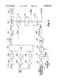
- FIG. 2comprises a block diagram illustrating a rotor position detector and a starting system control according to the present invention
- FIG. 3illustrates the inputs to and the outputs from the controller of FIG. 2;
- FIG. 4comprises a schematic diagram of the three-phase pulse-width modulated inverter of FIG. 2;
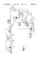
- FIG. 5comprises a block diagram of the rotor position detector of FIG. 2;
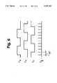
- FIG. 6illustrates the inputs to and the output from the logic circuit of FIG. 5;
- FIG. 7comprises a block diagram of the speed controller of FIG. 2;
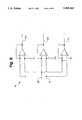
- FIG. 8comprises a circuit diagram of the phase converter of FIG. 2.
- a brushless, synchronous generator 10includes a permanent magnet generator (PMG) 12, an exciter portion 14 and a main generator portion 16.
- the generator 10further includes a motive power shaft 18 interconnecting a rotor 20 of the generator 10 and a prime mover 21, such as a gas turbine engine.
- a prime mover 21such as a gas turbine engine.
- the generator 10 and the prime mover 21 togethermay comprise an aircraft auxiliary power unit (APU) 22, although the present invention is equally useful in other prime mover/generator applications.
- APUaircraft auxiliary power unit
- the rotor 20carries one or more permanent magnets 23 which form poles for the PMG 12. Rotation of the motive power shaft 18 causes relative movement between the magnetic flux produced by the permanent magnet 23 and a set of three-phase PMG armature windings including phase windings 24a-24c mounted within a stator 26 of the generator 10.
- the exciter portion 14includes a field winding 28 disposed in the stator 26 and a set of three-phase armature windings 30a-30c disposed on the rotor 20.
- a set of rotating rectifiers 32interconnect the exciter armature windings 30a-30c and a main generator portion field winding 34 also disposed on the rotor 20.
- Three-phase main generator portion armature windings 36a-36care disposed in the stator 26.
- At least one, and preferably all three of the PMG armature windings 24a-24care coupled through a rectifier and voltage regulator (not shown) to the exciter portion field winding 28.
- a rectifier and voltage regulatornot shown
- the motive power shaft 18As the motive power shaft 18 is rotated, power produced in the PMG armature windings 24a-24c is rectified, regulated and delivered to the field winding 28.
- AC poweris produced in the armature windings 30a-30c, rectified by the rotating rectifiers 32 and applied to the main generator portion field winding 34.
- Rotation of the motive power shaft 18 and the field winding 34induces three-phase AC voltages in the main generator portion armature windings 36a-36c as is conventional.
- the AC voltagesare supplied through a contactor set 37 to an APU power distribution network 38 and thence to one or more loads (not shown).
- the brushless generator 10as a motor to bring a prime mover 21 up to self-sustaining speed.
- This operationis accomplished by providing electrical power to the main generator portion field winding 34 via the exciter 14, providing AC power to the main generator portion armature windings 36a-36c and suitably commutating the currents flowing in the windings 36a-36c to cause the motive power shaft 18 to rotate.
- the electrical power for the generator 10is developed by an APU start converter 39, FIG. 1B, which receives external electrical power and which is connected by contactor sets 40a, 40b to the exciter field winding 28 and the armature windings 36a-36c, respectively.
- FIG. 2illustrates the PMG 12, the main generator portion 16 and the motive power shaft 18 of the generator 10 together with a starting system control 41 for providing electrical power to the armature windings 36a-36c during operation of the generator 10 in the starting mode to convert electrical power into motive power. While not shown, power may also be provided to the exciter field winding 28, and thus to the exciter armature windings 30a-30c and thus to the main generator portion field windings 34 by any suitable means during operation in the starting mode. The application of power to the exciter field winding 28 forms no part of the present invention and will not be described in detail herein.
- the starting system control 41includes a rotor position detector 44 which is responsive to the phase outputs developed by the PMG 12, a voltage developed on one of a series of lines 45a-45c coupled to the main generator portion armature windings 36a-36c and a synchronization signal developed on a line 46 by the starting system control 41 as described in detail below.
- the rotor position detector 44develops signals representing the position and speed of the motive power shaft 18 and delivers the position signal to a speed controller 48.
- the speed controller 48develops a signal on a line 50 representing the mechanical position of the motive power shaft 18.
- the signal on the line 50is multiplied by a multiplier 52 with a signal representing the number of pairs of poles of the main generator, and the resulting signal is summed with a phase advance signal by a summer 54.
- the phase advance signalis developed by a function generator 56 and is dependent upon the speed of the motive power shaft as detected by the rotor position detector 44.
- the function generator 56provides increasing phase advance as speed increases in a high speed range.
- the summer 54develops an electrical angle command signal on a line 58 which is supplied to first and second functional blocks 60, 62 which generate cosine and sine waveform signals, respectively, each of which has the same frequency as the electrical angle command signal on the line 58.
- the sine signal and the cosine signalare supplied via a pair of lines 61, 63 to a 2-to-3 phase converter 64 which converts these signals into three-phase signals which are in turn supplied to three zero crossing detectors 66a-66c.
- Each of the zero crossing detectors 66a-66cdetects the zero crossings of one of the three-phase signals produced by the phase converter 64 to produce square-wave signals S a , S b , and S c , respectively, which are shown in FIG. 3 and which are separated in phase by 120°.
- An inverter controller 68responds to the signals S a , S b , and S c and to a power control signal delivered on a line 70 to produce on lines 72a-72f pulse-width modulated (PWM) inverter control waveforms T 1 , T 2 , T 5 and commutation signals T 2 , T 4 , T 6 which are shown in FIG. 3. If desired, the signals T 2 , T 4 , T 6 may also be pulse-width modulated.
- PWMpulse-width modulated
- the controller 68also produces the synchronization signal on the line 46.
- the synchronization signalcomprises a series of positive pulses each coinciding with time periods during which the current flowing in one of the main generator portion armature windings 36a-36c is zero.
- a three-phase pulse-width modulated inverter 74receives DC power over a DC link 76.
- the DC link 76may receive DC power from a three-phase rectifier 78 which is in turn coupled to an external AC source 79 or any other type of DC source.
- the three-phase pulse-width modulated inverter 74includes controllable power switches TR 1 -TR 6 and associated flyback diodes D1-D6 connected in a three-phase bridge configuration across DC link conductors 76a, 76b.
- the control waveforms T 1 , T 3 and T 5include PWM notches in the positive-going portions thereof. These signals control the power switches TR 1 , TR 3 and TR 5 , respectively, of the inverter 74.
- the control waveforms T 2 , T 4 and T 6control the inverter power switches TR 2 , TR 4 and TR 6 , respectively. These signals may also include PWM notches.
- the widths of the PWM notches of the control waveforms T 1 , T 3 and T 5are controlled by a power control circuit 80.
- the power control circuit 80includes a summer 82 which subtracts a signal representing the DC link current (which in turn represents the power delivered by the inverter 74 to the armature windings 36a-36c) from a power reference signal.
- the resulting power error signalis conditioned by a conditioner 84 which, preferably, comprises a proportionalintegral type compensator but could, alternatively, comprise any type of gain and compensation unit.
- the output of the conditioner 84is delivered to a controlled or adjustable limiter 86 which produces the power control 10 signal on the line 70.
- the limiter 86is controlled in accordance with a limiter control signal.
- the speed indication produced by the rotor position detector 44is delivered to a multiplier 88 and multiplied by a constant volts-per-hertz signal to produce a speed dependent voltage signal.
- the speed dependent voltage signalis summed with a constant boost voltage by a summer 90, which in turn produces the limiter control signal.
- the constant boost voltage signalis proportional to the IR voltage drop in the main generator portion control windings and allows the power control signal to overcome these losses at initial start-up.
- the multiplier 88produces a ramping signal which, when added to the boost voltage, increases the adjustable limit of the limiter 86 so that increasing power magnitudes can be delivered to the armature windings 36a-36c by the inverter 74.
- FIG. 6illustrates three waveforms S d , S e , and S f representing the outputs of the zero crossing detectors 102a-102c, respectively.
- the logic circuit 104From the waveforms S d -S f , the logic circuit 104 develops a signal S g which, as shown in FIG. 6, consists of a narrow pulse every 60 electrical degrees.
- the waveform S gis provided by the logic circuit 104 to a delay circuit 106.
- the delay circuit 106provides a reset signal to a counter 108 which accumulates clock pulses produced by a clock 110.
- the counter 108is reset every 60° with respect to the output waveforms of the PMG 12, and thus every 60° of rotation of the motive power shaft 18.
- the output of the counter 108represents the time that elapses between each pulse in the waveform S g .
- the falling edge of each pulsecomprises a write command to a latch 112 which latches the output of the counter 108.
- the output of the latch 112is inverted, i.e., the reciprocal thereof is calculated, by a circuit 114 to obtain an indication of the speed of the motive power shaft 18.
- the output of the circuit 114is supplied to an integrator 116 which integrates the speed signal to generate a signal representative of the position of the motive power shaft 118.
- the integrator 116is reset once per full revolution of the motive power shaft 18 by an input conditioner 120, preferably comprising a gain amplifier, a zero crossing detector 122, a frequency divider 124 and a one-shot 26.
- the input conditioner 120scales one of the phase voltages from one of the main generator portion armature windings 36a-36c, e.g., the voltage appearing on the line 45a of FIG. 2.
- the synchronization signal on the line 46enables the zero crossing detector 122 for a short period of time surrounding each expected zero crossing of the phase voltage V shown in FIG. 3 to provide a degree of noise immunity.
- the frequency divider 124divides the frequency of the waveform produced by the zero crossing detector 122 by an amount equal to the number of poles in the main generator rotor and produces a signal to drive the one-shot 126 to reset the integrator 116 once every rotation of the motive power shaft 18.
- the reset signal provided to the integrator 116could be generated without the need to supply the synchronization signal to the zero crossing detector 122 by incorporating a low pass filter between the input conditioner 120 and the zero crossing detector 122.
- the cutoff frequency of the low pass filterwould be selected to reject the PWM frequency (the high-frequency notches shown in the waveforms T 1 , T 3 , T 5 of FIG. 3) and its harmonics.
- the divider circuit 124would divide by the number of poles divided by two, or P/2.
- FIG. 7illustrates the speed controller 48 in greater detail.
- a speed command signalmay be developed on a line 130 which is coupled to a non-inverting input of a summer 132.
- the speed commandmay comprise a step voltage from a first voltage to a second, higher voltage or may comprise any other type of waveform as desired.
- the output of the summer 132is coupled to a function generator 134 which develops an acceleration command signal which is, in turn, integrated by an integrator 136 to produce a speed reference signal.
- the speed reference signalis fed back to an inverting input of the summer 132, and hence the elements 132, 134, and 136 comprise a closed-loop circuit.
- the speed reference signalis integrated by a further integrator 138 to develop a position reference signal which is, in turn, provided to a controllable switch 140 and to a non-inverting input of a summer 142.
- the angular position indicationcomprising the position signal from the integrator 116 of FIG. 5 is also provided to the controllable switch 140 and is further provided to an inverting input of the summer 142.
- the summer 142produces a position error signal indicative of the error between the derived position reference signal and the actual rotor position as developed by the integrator 116.
- the position error signalis provided to an error comparator 144 which compares the position error signal to an error reference and produces a high state signal on a line 146 when the position error signal is less than the error reference.
- the speed reference signal produced by the integrator 136is delivered to an inverting input of a summer 148 while a valid speed reference signal, indicative of the value at which the speed reference signal becomes a reliable representation of the speed of the motive power shaft, is delivered to a non-inverting input of the summer 148.
- the summer 148produces a signal indicative of the difference between the speed reference signal and the valid speed reference signal.
- a zero crossing detector 150detects when the speed reference signal equals or exceeds the valid speed reference signal and produces a high state output signal on a line 152 at such time.
- the summer 148 in conjunction with the zero crossing detector 150thus comprise a speed comparator 154.
- the signals on the lines 146 and 152are delivered to an AND gate 156 having an output which is coupled to and controls the controllable switch 140.
- the controllable switch 140is set to a position which passes the output of the integrator 138 to the output of the switch 140, and thus to the multiplier 52 of FIG. 2. Also at this time, power is applied to the exciter portion 14, and hence to the main generation portion field winding 34 of FIG. 1A, and power is also applied to the main generator armature windings 36a-36c. The motive power shaft 18 is thus accelerated.
- the position reference signal, as derived by the integrator 138,is less than the error reference and when the speed reference signal produced by the integrator 136 is equal to or greater than the valid speed reference, the high-state signals on the lines 146 and 152 cause the AND gate 156 to move the controllable switch 140 to the position shown in FIG. 7.
- the controllable switch 140is latched in such position so that the output of the integrator 116 of FIG. 5 is thereafter provided to the multiplier 52 of FIG. 2.
- the switch 140remains latched until a new start-up sequence is initialized.
Landscapes
- Engineering & Computer Science (AREA)
- Chemical & Material Sciences (AREA)
- Combustion & Propulsion (AREA)
- Mechanical Engineering (AREA)
- General Engineering & Computer Science (AREA)
- Power Engineering (AREA)
- Control Of Eletrric Generators (AREA)
Abstract
Description
E.sub.emf =Kω Sin α
Claims (31)
Priority Applications (1)
| Application Number | Priority Date | Filing Date | Title |
|---|---|---|---|
| US08/061,496US5495163A (en) | 1993-05-12 | 1993-05-12 | Control for a brushless generator operable in generating and starting modes |
Applications Claiming Priority (1)
| Application Number | Priority Date | Filing Date | Title |
|---|---|---|---|
| US08/061,496US5495163A (en) | 1993-05-12 | 1993-05-12 | Control for a brushless generator operable in generating and starting modes |
Publications (1)
| Publication Number | Publication Date |
|---|---|
| US5495163Atrue US5495163A (en) | 1996-02-27 |
Family
ID=22036164
Family Applications (1)
| Application Number | Title | Priority Date | Filing Date |
|---|---|---|---|
| US08/061,496Expired - LifetimeUS5495163A (en) | 1993-05-12 | 1993-05-12 | Control for a brushless generator operable in generating and starting modes |
Country Status (1)
| Country | Link |
|---|---|
| US (1) | US5495163A (en) |
Cited By (54)
| Publication number | Priority date | Publication date | Assignee | Title |
|---|---|---|---|---|
| US5646496A (en)* | 1994-11-08 | 1997-07-08 | Dana Corporation | Apparatus and method for generating digital position signals for a rotatable shaft |
| US5689175A (en)* | 1996-05-31 | 1997-11-18 | Sundstrand Corporation | Voltage regulator for an electrical power system |
| US5920162A (en)* | 1996-08-05 | 1999-07-06 | Sundstrand Corporation | Position control using variable exciter feed through |
| US6118238A (en)* | 1998-08-26 | 2000-09-12 | Satcon Technology Corporation | Motor starting apparatus for an engine driven generator |
| US6486640B2 (en)* | 2000-02-22 | 2002-11-26 | Lucas Industries Limited | Control system for variable frequency generator |
| US6487096B1 (en) | 1997-09-08 | 2002-11-26 | Capstone Turbine Corporation | Power controller |
| US20020175522A1 (en)* | 2001-01-30 | 2002-11-28 | Joel Wacknov | Distributed power system |
| US20020198648A1 (en)* | 1998-01-05 | 2002-12-26 | Mark Gilbreth | Method and system for control of turbogenerator power and temperature |
| US20030015873A1 (en)* | 2001-01-10 | 2003-01-23 | Claude Khalizadeh | Transient ride-through or load leveling power distribution system |
| US20030080701A1 (en)* | 2001-10-25 | 2003-05-01 | Hitachi, Ltd. | Apparatus and method of sensorless control for synchronous generator |
| US20030085691A1 (en)* | 2001-11-02 | 2003-05-08 | Yuan Yao | Control system for regulating exciter power for a brushless synchronous generator |
| US6583995B2 (en)* | 2000-12-21 | 2003-06-24 | Honeywell International Inc. | Permanent magnet generator and generator control |
| US6612112B2 (en) | 1998-12-08 | 2003-09-02 | Capstone Turbine Corporation | Transient turbine exhaust temperature control for a turbogenerator |
| US20040119291A1 (en)* | 1998-04-02 | 2004-06-24 | Capstone Turbine Corporation | Method and apparatus for indirect catalytic combustor preheating |
| US20040135436A1 (en)* | 1998-04-02 | 2004-07-15 | Gilbreth Mark G | Power controller system and method |
| US20040148942A1 (en)* | 2003-01-31 | 2004-08-05 | Capstone Turbine Corporation | Method for catalytic combustion in a gas- turbine engine, and applications thereof |
| US6784565B2 (en) | 1997-09-08 | 2004-08-31 | Capstone Turbine Corporation | Turbogenerator with electrical brake |
| US6809496B2 (en) | 2002-09-16 | 2004-10-26 | Honeywell International Inc. | Position sensor emulator for a synchronous motor/generator |
| US6836086B1 (en) | 2002-03-08 | 2004-12-28 | Hamilton Sundstrand Corporation | Controlled starting system for a gas turbine engine |
| US20050035815A1 (en)* | 2003-08-13 | 2005-02-17 | Louis Cheng | Active filter for multi-phase ac power system |
| US20050184698A1 (en)* | 2004-02-20 | 2005-08-25 | Anghel Cristian E. | Position sensing method and apparatus for synchronous motor generator system |
| US6960840B2 (en) | 1998-04-02 | 2005-11-01 | Capstone Turbine Corporation | Integrated turbine power generation system with catalytic reactor |
| US20060103341A1 (en)* | 2004-11-15 | 2006-05-18 | General Electric Company | Bidirectional buck-boost power converters, electric starter generator system employing bidirectional buck-boost power converters, and methods therefor |
| US20060144396A1 (en)* | 2003-08-04 | 2006-07-06 | Devries Douglas F | Portable ventilator system |
| US7106020B1 (en) | 2005-08-30 | 2006-09-12 | Honeywell International Inc. | Method of operating a brushless DC motor |
| US7116073B1 (en) | 2005-08-10 | 2006-10-03 | Innovative Power Solutions, Llc | Methods and apparatus for controlling a motor/generator |
| US20060249153A1 (en)* | 2003-08-04 | 2006-11-09 | Pulmonetic Systems, Inc. | Mechanical ventilation system utilizing bias valve |
| US7135829B1 (en) | 2005-08-10 | 2006-11-14 | Innovative Power Solutions, Llc | Methods and apparatus for controlling a motor/generator |
| US20070000490A1 (en)* | 2003-08-04 | 2007-01-04 | Devries Douglas F | Portable ventilator system |
| US20070132245A1 (en)* | 2005-09-15 | 2007-06-14 | Hamilton Sundstrand Corporation | Electrical starter generator system for a gas turbine engine |
| US7265512B2 (en) | 2005-08-30 | 2007-09-04 | Honeywell International Inc. | Actuator with feedback for end stop positioning |
| US20080042626A1 (en)* | 2006-07-03 | 2008-02-21 | Honda Motor Co., Ltd. | Output voltage controller of engine-driven generator |
| US20080079262A1 (en)* | 2006-09-29 | 2008-04-03 | Honeywell International, Inc. | Engine starter-generator optimized for start function |
| US20080092893A1 (en)* | 2003-08-04 | 2008-04-24 | Pulmonetic Systems, Inc. | Compressor control system for a portable ventilator |
| US20080111512A1 (en)* | 2006-11-09 | 2008-05-15 | Honeywell International Inc. | Actuator position switch |
| US20080315584A1 (en)* | 2007-06-20 | 2008-12-25 | Rozman Gregory I | Engine start system with a regulated permanent magnet machine |
| USRE40713E1 (en) | 1997-09-08 | 2009-05-19 | Capstone Turbine Corporation | Turbogenerator/motor controller |
| US20090251089A1 (en)* | 2008-04-02 | 2009-10-08 | Temic Automotive Of North America, Inc. | Systems and Methods for Detecting Angular Position |
| US20090251109A1 (en)* | 2008-04-04 | 2009-10-08 | General Electric Company | Systems and methods involving starting variable speed generators |
| US20100094480A1 (en)* | 2006-09-29 | 2010-04-15 | Aengquist Lennart | Apparatus and a method for a power transmission system |
| US20100123421A1 (en)* | 2008-11-18 | 2010-05-20 | Honeywell International Inc. | Hvac actuator with output torque compensation |
| US20100194326A1 (en)* | 2009-01-30 | 2010-08-05 | Honeywell International Inc. | Hvac actuator with internal heating |
| US8121811B2 (en) | 2008-04-02 | 2012-02-21 | Continental Automotive Systems, Inc. | Systems and methods for detecting angular position |
| US8466646B2 (en) | 2008-04-02 | 2013-06-18 | Continental Automotive Systems, Inc. | Apparatus and method for determining angular position |
| CN103308868A (en)* | 2013-07-09 | 2013-09-18 | 南昌航空大学 | Airplane power source system control and protection experiment device |
| US20140062360A1 (en)* | 2012-09-06 | 2014-03-06 | Sanyo Denki Co., Ltd. | Motor control device and motor control method |
| US20150048805A1 (en)* | 2013-08-16 | 2015-02-19 | National Cheng Kung University | Power conversion apparatus and control method thereof |
| EP2299586A3 (en)* | 2009-08-28 | 2015-04-29 | Hamilton Sundstrand Corporation | Active rectification for a variable-frequency synchronous generator |
| US9252695B2 (en)* | 2014-03-12 | 2016-02-02 | General Electric Company | Brushless permanent magnet generator plus auxiliary voltage source constant potential exciter |
| EP2337216A3 (en)* | 2009-12-15 | 2016-11-30 | Astronics Advanced Electronic Systems Corp. | Dual purpose permanent magnets for a speed sensor and a generator |
| US10770997B2 (en)* | 2018-05-30 | 2020-09-08 | Rolls-Royce Plc | Power system |
| US10931217B2 (en) | 2018-05-30 | 2021-02-23 | Rolls-Royce Plc | Power system |
| CN112555080A (en)* | 2020-12-09 | 2021-03-26 | 重庆大学 | Preheating device for engine and storage battery |
| US11079255B2 (en) | 2018-05-30 | 2021-08-03 | Rolls-Royce Plc | Angle determination for a generator |
Citations (51)
| Publication number | Priority date | Publication date | Assignee | Title |
|---|---|---|---|---|
| US3775974A (en)* | 1972-06-05 | 1973-12-04 | J Silver | Gas turbine engine |
| US3858109A (en)* | 1973-03-23 | 1974-12-31 | Sperry Rand Corp | Brushless tachometer |
| US3902073A (en)* | 1974-02-07 | 1975-08-26 | Gen Electric | Starter generator electrical system utilizing phase controlled rectifiers to drive a dynamoelectric machine as a brushless dc motor in the starter mode and to provide frequency conversion for a constant frequency output in the generating mode |
| US3908161A (en)* | 1974-02-07 | 1975-09-23 | Gen Electric | Field excitation system for synchronous machines utilizing a rotating transformer brushless exciter generating combination |
| US4093869A (en)* | 1976-04-13 | 1978-06-06 | Westinghouse Electric Corp. | Quadrature axis field brushless exciter |
| US4295085A (en)* | 1979-05-25 | 1981-10-13 | General Electric Company | Phase lock loop commutation position control and method |
| US4354126A (en)* | 1980-09-12 | 1982-10-12 | Westinghouse Electric Corp. | Dynamoelectric machine with a permanent magnet rotor having laminated poles |
| US4456830A (en)* | 1982-04-22 | 1984-06-26 | Lockheed Corporation | AC Motor-starting for aircraft engines using APU free turbine driven generators |
| US4473752A (en)* | 1982-05-27 | 1984-09-25 | Lockheed Corporation | Aircraft engine starting with synchronous ac generator |
| US4684081A (en)* | 1986-06-11 | 1987-08-04 | Lockheed Corporation | Multifunction power system for an aircraft |
| US4687961A (en)* | 1986-03-17 | 1987-08-18 | Seiberco Incorporated | Polyphase DC motor with sensor poles |
| US4694210A (en)* | 1986-07-31 | 1987-09-15 | General Motors Corporation | Brushless DC motor and sensorless drive arrangement therefor |
| US4708030A (en)* | 1985-03-18 | 1987-11-24 | Sundstrand Corporation | Multi-range starter-generator drive |
| US4743777A (en)* | 1986-03-07 | 1988-05-10 | Westinghouse Electric Corp. | Starter generator system with two stator exciter windings |
| US4772802A (en)* | 1987-08-19 | 1988-09-20 | Sundstrand Corporation | Starting/generating system |
| GB2206751A (en)* | 1987-05-29 | 1989-01-11 | Shinko Electric Co Ltd | Starting a variable speed constant frequency generating system |
| US4808903A (en)* | 1987-04-13 | 1989-02-28 | Hitachi, Ltd. | Vector control system for induction motors |
| US4841216A (en)* | 1987-07-24 | 1989-06-20 | Shinko Electric Co., Ltd. | Engine start type VSCF generating system |
| US4868406A (en)* | 1988-07-05 | 1989-09-19 | Sundstrand Corporation | Electrically compensated constant speed drive with prime mover start capability |
| US4900231A (en)* | 1986-05-30 | 1990-02-13 | The Boeing Company | Auxiliary compressor air supply for an aircraft |
| US4933623A (en)* | 1988-12-29 | 1990-06-12 | Westinghouse Electric Corp. | Generator voltage regulator power circuit |
| US4935686A (en)* | 1989-08-18 | 1990-06-19 | Westinghouse Electric Corp. | Ac motor drive with switched autotransformer coupling |
| US4939441A (en)* | 1989-10-27 | 1990-07-03 | Sundstrand Corporation | Excitation system for a brushless generator having separate AC and DC exciter field windings |
| US4942493A (en)* | 1988-11-02 | 1990-07-17 | Sundstrand Corporation | Method and apparatus for detecting prime mover start malfunction |
| US4947100A (en)* | 1989-10-16 | 1990-08-07 | Sundstrand Corporation | Power conversion system with stepped waveform inverter having prime mover start capability |
| US4949021A (en)* | 1988-11-14 | 1990-08-14 | Sunstrand Corporation | Variable speed constant frequency start system with selectable input power limiting |
| US4959595A (en)* | 1988-02-12 | 1990-09-25 | Mitsubishi Denki Kabushiki Kaisha | Rotating electric machine having a coil coaxial with rotating shaft |
| US4967334A (en)* | 1989-09-12 | 1990-10-30 | Sundstrand Corporation | Inverter input/output filter system |
| US4968926A (en)* | 1989-10-25 | 1990-11-06 | Sundstrand Corporation | Power conversion system with stepped waveform DC to AC converter having prime mover start capability |
| US4988939A (en)* | 1989-08-04 | 1991-01-29 | Thor Technology Corporation | Electric motor with variable commutation delay |
| US4992721A (en)* | 1990-01-26 | 1991-02-12 | Sundstrand Corporation | Inverter for starting/generating system |
| US5008801A (en)* | 1989-12-11 | 1991-04-16 | Sundstrand Corporation | VSCF power conversion system using an output autotransformer |
| US5012177A (en)* | 1989-12-19 | 1991-04-30 | Sundstrand Corporation | Power conversion system using a switched reluctance motor/generator |
| US5013929A (en)* | 1989-11-22 | 1991-05-07 | Sundstrand Corporation | Power conversion system having prime mover start capability |
| US5015941A (en)* | 1989-10-30 | 1991-05-14 | Sundstrand Corporation | Power conversion system with bi-directional power converter having prime mover start capability |
| US5015927A (en)* | 1989-08-04 | 1991-05-14 | Thor Technology Corporation | Electric motor with regeneration current commutation |
| US5028803A (en)* | 1989-03-22 | 1991-07-02 | Sundstrand Corporation | Integrated drive generator system with direct motor drive prime mover starting |
| US5040366A (en)* | 1989-01-13 | 1991-08-20 | General Electric Company | Fluid transfer device |
| US5051670A (en)* | 1990-07-30 | 1991-09-24 | Aircraft Parts Corp. | Aircraft DC starter-generator torque controller |
| US5055764A (en)* | 1989-12-11 | 1991-10-08 | Sundstrand Corporation | Low voltage aircraft engine starting system |
| US5055700A (en)* | 1989-10-16 | 1991-10-08 | Dhyanchand P John | Brushless generator having prime mover start capability |
| US5068590A (en)* | 1989-12-20 | 1991-11-26 | Sundstrand Corporation | Brushless generator having AC excitation in generating and starting modes |
| US5079494A (en)* | 1989-05-23 | 1992-01-07 | Thor Technology Corporation | Fast response motor current regulator |
| US5097195A (en)* | 1989-11-27 | 1992-03-17 | Sundstrand Corporation | AC exciter for VSCF starter/generator |
| US5113125A (en)* | 1991-05-01 | 1992-05-12 | Westinghouse Electric Corp. | AC drive with optimized torque |
| US5132604A (en)* | 1989-04-04 | 1992-07-21 | Honda Giken Kogyo Kabushiki Kaisha | Engine starter and electric generator system |
| US5140245A (en)* | 1990-09-24 | 1992-08-18 | Westinghouse Electric Corp. | Pmg-based position sensor and synchronous drive incorporating same |
| US5202613A (en)* | 1991-05-28 | 1993-04-13 | Kruse David L | Two-phase brushless DC motor controller |
| US5221881A (en)* | 1991-10-03 | 1993-06-22 | Sgs-Thomson Microelectronics, Inc. | Method and apparatus for operating polyphase DC motors |
| US5349257A (en)* | 1993-04-06 | 1994-09-20 | Sundstrand Corporation | Permanent magnet generator with a position sensing coil |
| US5384527A (en)* | 1993-05-12 | 1995-01-24 | Sundstrand Corporation | Rotor position detector with back EMF voltage estimation |
- 1993
- 1993-05-12USUS08/061,496patent/US5495163A/ennot_activeExpired - Lifetime
Patent Citations (51)
| Publication number | Priority date | Publication date | Assignee | Title |
|---|---|---|---|---|
| US3775974A (en)* | 1972-06-05 | 1973-12-04 | J Silver | Gas turbine engine |
| US3858109A (en)* | 1973-03-23 | 1974-12-31 | Sperry Rand Corp | Brushless tachometer |
| US3902073A (en)* | 1974-02-07 | 1975-08-26 | Gen Electric | Starter generator electrical system utilizing phase controlled rectifiers to drive a dynamoelectric machine as a brushless dc motor in the starter mode and to provide frequency conversion for a constant frequency output in the generating mode |
| US3908161A (en)* | 1974-02-07 | 1975-09-23 | Gen Electric | Field excitation system for synchronous machines utilizing a rotating transformer brushless exciter generating combination |
| US4093869A (en)* | 1976-04-13 | 1978-06-06 | Westinghouse Electric Corp. | Quadrature axis field brushless exciter |
| US4295085A (en)* | 1979-05-25 | 1981-10-13 | General Electric Company | Phase lock loop commutation position control and method |
| US4354126A (en)* | 1980-09-12 | 1982-10-12 | Westinghouse Electric Corp. | Dynamoelectric machine with a permanent magnet rotor having laminated poles |
| US4456830A (en)* | 1982-04-22 | 1984-06-26 | Lockheed Corporation | AC Motor-starting for aircraft engines using APU free turbine driven generators |
| US4473752A (en)* | 1982-05-27 | 1984-09-25 | Lockheed Corporation | Aircraft engine starting with synchronous ac generator |
| US4708030A (en)* | 1985-03-18 | 1987-11-24 | Sundstrand Corporation | Multi-range starter-generator drive |
| US4743777A (en)* | 1986-03-07 | 1988-05-10 | Westinghouse Electric Corp. | Starter generator system with two stator exciter windings |
| US4687961A (en)* | 1986-03-17 | 1987-08-18 | Seiberco Incorporated | Polyphase DC motor with sensor poles |
| US4900231A (en)* | 1986-05-30 | 1990-02-13 | The Boeing Company | Auxiliary compressor air supply for an aircraft |
| US4684081A (en)* | 1986-06-11 | 1987-08-04 | Lockheed Corporation | Multifunction power system for an aircraft |
| US4694210A (en)* | 1986-07-31 | 1987-09-15 | General Motors Corporation | Brushless DC motor and sensorless drive arrangement therefor |
| US4808903A (en)* | 1987-04-13 | 1989-02-28 | Hitachi, Ltd. | Vector control system for induction motors |
| GB2206751A (en)* | 1987-05-29 | 1989-01-11 | Shinko Electric Co Ltd | Starting a variable speed constant frequency generating system |
| US4841216A (en)* | 1987-07-24 | 1989-06-20 | Shinko Electric Co., Ltd. | Engine start type VSCF generating system |
| US4772802A (en)* | 1987-08-19 | 1988-09-20 | Sundstrand Corporation | Starting/generating system |
| US4959595A (en)* | 1988-02-12 | 1990-09-25 | Mitsubishi Denki Kabushiki Kaisha | Rotating electric machine having a coil coaxial with rotating shaft |
| US4868406A (en)* | 1988-07-05 | 1989-09-19 | Sundstrand Corporation | Electrically compensated constant speed drive with prime mover start capability |
| US4942493A (en)* | 1988-11-02 | 1990-07-17 | Sundstrand Corporation | Method and apparatus for detecting prime mover start malfunction |
| US4949021A (en)* | 1988-11-14 | 1990-08-14 | Sunstrand Corporation | Variable speed constant frequency start system with selectable input power limiting |
| US4933623A (en)* | 1988-12-29 | 1990-06-12 | Westinghouse Electric Corp. | Generator voltage regulator power circuit |
| US5040366A (en)* | 1989-01-13 | 1991-08-20 | General Electric Company | Fluid transfer device |
| US5028803A (en)* | 1989-03-22 | 1991-07-02 | Sundstrand Corporation | Integrated drive generator system with direct motor drive prime mover starting |
| US5132604A (en)* | 1989-04-04 | 1992-07-21 | Honda Giken Kogyo Kabushiki Kaisha | Engine starter and electric generator system |
| US5079494A (en)* | 1989-05-23 | 1992-01-07 | Thor Technology Corporation | Fast response motor current regulator |
| US5015927A (en)* | 1989-08-04 | 1991-05-14 | Thor Technology Corporation | Electric motor with regeneration current commutation |
| US4988939A (en)* | 1989-08-04 | 1991-01-29 | Thor Technology Corporation | Electric motor with variable commutation delay |
| US4935686A (en)* | 1989-08-18 | 1990-06-19 | Westinghouse Electric Corp. | Ac motor drive with switched autotransformer coupling |
| US4967334A (en)* | 1989-09-12 | 1990-10-30 | Sundstrand Corporation | Inverter input/output filter system |
| US4947100A (en)* | 1989-10-16 | 1990-08-07 | Sundstrand Corporation | Power conversion system with stepped waveform inverter having prime mover start capability |
| US5055700A (en)* | 1989-10-16 | 1991-10-08 | Dhyanchand P John | Brushless generator having prime mover start capability |
| US4968926A (en)* | 1989-10-25 | 1990-11-06 | Sundstrand Corporation | Power conversion system with stepped waveform DC to AC converter having prime mover start capability |
| US4939441A (en)* | 1989-10-27 | 1990-07-03 | Sundstrand Corporation | Excitation system for a brushless generator having separate AC and DC exciter field windings |
| US5015941A (en)* | 1989-10-30 | 1991-05-14 | Sundstrand Corporation | Power conversion system with bi-directional power converter having prime mover start capability |
| US5013929A (en)* | 1989-11-22 | 1991-05-07 | Sundstrand Corporation | Power conversion system having prime mover start capability |
| US5097195A (en)* | 1989-11-27 | 1992-03-17 | Sundstrand Corporation | AC exciter for VSCF starter/generator |
| US5008801A (en)* | 1989-12-11 | 1991-04-16 | Sundstrand Corporation | VSCF power conversion system using an output autotransformer |
| US5055764A (en)* | 1989-12-11 | 1991-10-08 | Sundstrand Corporation | Low voltage aircraft engine starting system |
| US5012177A (en)* | 1989-12-19 | 1991-04-30 | Sundstrand Corporation | Power conversion system using a switched reluctance motor/generator |
| US5068590A (en)* | 1989-12-20 | 1991-11-26 | Sundstrand Corporation | Brushless generator having AC excitation in generating and starting modes |
| US4992721A (en)* | 1990-01-26 | 1991-02-12 | Sundstrand Corporation | Inverter for starting/generating system |
| US5051670A (en)* | 1990-07-30 | 1991-09-24 | Aircraft Parts Corp. | Aircraft DC starter-generator torque controller |
| US5140245A (en)* | 1990-09-24 | 1992-08-18 | Westinghouse Electric Corp. | Pmg-based position sensor and synchronous drive incorporating same |
| US5113125A (en)* | 1991-05-01 | 1992-05-12 | Westinghouse Electric Corp. | AC drive with optimized torque |
| US5202613A (en)* | 1991-05-28 | 1993-04-13 | Kruse David L | Two-phase brushless DC motor controller |
| US5221881A (en)* | 1991-10-03 | 1993-06-22 | Sgs-Thomson Microelectronics, Inc. | Method and apparatus for operating polyphase DC motors |
| US5349257A (en)* | 1993-04-06 | 1994-09-20 | Sundstrand Corporation | Permanent magnet generator with a position sensing coil |
| US5384527A (en)* | 1993-05-12 | 1995-01-24 | Sundstrand Corporation | Rotor position detector with back EMF voltage estimation |
Non-Patent Citations (5)
| Title |
|---|
| A. E. Fitzgerald, et al., Electric Machinery, 246 249, 270 271.* |
| A. E. Fitzgerald, et al., Electric Machinery, 246-249, 270-271. |
| E. Iizuka, et al., IEEE Transactions on Industry Applications, vol. 1A 21, No. 4, May/Jun. 1985.* |
| E. Iizuka, et al., IEEE Transactions on Industry Applications, vol. 1A-21, No. 4, May/Jun. 1985. |
| Furuhashi, et al., IEEE Transactions on Industrial Electronics, vol. 39, No. 2, Apr. 1992.* |
Cited By (87)
| Publication number | Priority date | Publication date | Assignee | Title |
|---|---|---|---|---|
| US5646496A (en)* | 1994-11-08 | 1997-07-08 | Dana Corporation | Apparatus and method for generating digital position signals for a rotatable shaft |
| US5760562A (en)* | 1994-11-08 | 1998-06-02 | Dana Corporation | Apparatus and method for generating digital position signals for a rotatable shaft |
| US5689175A (en)* | 1996-05-31 | 1997-11-18 | Sundstrand Corporation | Voltage regulator for an electrical power system |
| US5920162A (en)* | 1996-08-05 | 1999-07-06 | Sundstrand Corporation | Position control using variable exciter feed through |
| US6487096B1 (en) | 1997-09-08 | 2002-11-26 | Capstone Turbine Corporation | Power controller |
| US6784565B2 (en) | 1997-09-08 | 2004-08-31 | Capstone Turbine Corporation | Turbogenerator with electrical brake |
| USRE40713E1 (en) | 1997-09-08 | 2009-05-19 | Capstone Turbine Corporation | Turbogenerator/motor controller |
| US6870279B2 (en) | 1998-01-05 | 2005-03-22 | Capstone Turbine Corporation | Method and system for control of turbogenerator power and temperature |
| US20020198648A1 (en)* | 1998-01-05 | 2002-12-26 | Mark Gilbreth | Method and system for control of turbogenerator power and temperature |
| US20040119291A1 (en)* | 1998-04-02 | 2004-06-24 | Capstone Turbine Corporation | Method and apparatus for indirect catalytic combustor preheating |
| US6960840B2 (en) | 1998-04-02 | 2005-11-01 | Capstone Turbine Corporation | Integrated turbine power generation system with catalytic reactor |
| US20040135436A1 (en)* | 1998-04-02 | 2004-07-15 | Gilbreth Mark G | Power controller system and method |
| US6118238A (en)* | 1998-08-26 | 2000-09-12 | Satcon Technology Corporation | Motor starting apparatus for an engine driven generator |
| US6612112B2 (en) | 1998-12-08 | 2003-09-02 | Capstone Turbine Corporation | Transient turbine exhaust temperature control for a turbogenerator |
| US6486640B2 (en)* | 2000-02-22 | 2002-11-26 | Lucas Industries Limited | Control system for variable frequency generator |
| US6583995B2 (en)* | 2000-12-21 | 2003-06-24 | Honeywell International Inc. | Permanent magnet generator and generator control |
| US20030015873A1 (en)* | 2001-01-10 | 2003-01-23 | Claude Khalizadeh | Transient ride-through or load leveling power distribution system |
| US6787933B2 (en) | 2001-01-10 | 2004-09-07 | Capstone Turbine Corporation | Power generation system having transient ride-through/load-leveling capabilities |
| US20020175522A1 (en)* | 2001-01-30 | 2002-11-28 | Joel Wacknov | Distributed power system |
| US6720753B2 (en)* | 2001-10-25 | 2004-04-13 | Hitachi, Ltd. | Power generation system using synchronous generator |
| US20030080701A1 (en)* | 2001-10-25 | 2003-05-01 | Hitachi, Ltd. | Apparatus and method of sensorless control for synchronous generator |
| US6909262B2 (en) | 2001-11-02 | 2005-06-21 | Honeywell International Inc. | Control system for regulating exciter power for a brushless synchronous generator |
| US20030085691A1 (en)* | 2001-11-02 | 2003-05-08 | Yuan Yao | Control system for regulating exciter power for a brushless synchronous generator |
| US6836086B1 (en) | 2002-03-08 | 2004-12-28 | Hamilton Sundstrand Corporation | Controlled starting system for a gas turbine engine |
| US6809496B2 (en) | 2002-09-16 | 2004-10-26 | Honeywell International Inc. | Position sensor emulator for a synchronous motor/generator |
| US20040148942A1 (en)* | 2003-01-31 | 2004-08-05 | Capstone Turbine Corporation | Method for catalytic combustion in a gas- turbine engine, and applications thereof |
| US20070000490A1 (en)* | 2003-08-04 | 2007-01-04 | Devries Douglas F | Portable ventilator system |
| US8677995B2 (en)* | 2003-08-04 | 2014-03-25 | Carefusion 203, Inc. | Compressor control system for a portable ventilator |
| US20080092893A1 (en)* | 2003-08-04 | 2008-04-24 | Pulmonetic Systems, Inc. | Compressor control system for a portable ventilator |
| US8118024B2 (en) | 2003-08-04 | 2012-02-21 | Carefusion 203, Inc. | Mechanical ventilation system utilizing bias valve |
| US20060144396A1 (en)* | 2003-08-04 | 2006-07-06 | Devries Douglas F | Portable ventilator system |
| US8297279B2 (en) | 2003-08-04 | 2012-10-30 | Carefusion 203, Inc. | Portable ventilator system |
| US10118011B2 (en) | 2003-08-04 | 2018-11-06 | Carefusion 203, Inc. | Mechanical ventilation system utilizing bias valve |
| US20060249153A1 (en)* | 2003-08-04 | 2006-11-09 | Pulmonetic Systems, Inc. | Mechanical ventilation system utilizing bias valve |
| US20080092892A1 (en)* | 2003-08-04 | 2008-04-24 | Pulmonetic Systems, Inc. | Compressor Control System for a Portable Ventilator |
| US8522780B2 (en) | 2003-08-04 | 2013-09-03 | Carefusion 203, Inc. | Portable ventilator system |
| US8156937B2 (en) | 2003-08-04 | 2012-04-17 | Carefusion 203, Inc. | Portable ventilator system |
| US20070163589A1 (en)* | 2003-08-04 | 2007-07-19 | Devries Douglas F | Portable ventilator system |
| US8683997B2 (en) | 2003-08-04 | 2014-04-01 | Carefusion 203, Inc. | Portable ventilator system |
| US9126002B2 (en) | 2003-08-04 | 2015-09-08 | Carefusion 203, Inc. | Mechanical ventilation system utilizing bias valve |
| US20080053438A1 (en)* | 2003-08-04 | 2008-03-06 | Devries Douglas F | Portable ventilator system |
| US20050035815A1 (en)* | 2003-08-13 | 2005-02-17 | Louis Cheng | Active filter for multi-phase ac power system |
| US6861897B1 (en) | 2003-08-13 | 2005-03-01 | Honeywell International Inc. | Active filter for multi-phase AC power system |
| US20050184698A1 (en)* | 2004-02-20 | 2005-08-25 | Anghel Cristian E. | Position sensing method and apparatus for synchronous motor generator system |
| US7045986B2 (en) | 2004-02-20 | 2006-05-16 | Honeywell International Inc. | Position sensing method and apparatus for synchronous motor generator system |
| US20080094019A1 (en)* | 2004-11-15 | 2008-04-24 | General Electric Company | Bidirectional buck-boost power converters |
| US7327113B2 (en) | 2004-11-15 | 2008-02-05 | General Electric Company | Electric starter generator system employing bidirectional buck-boost power converters, and methods therefor |
| US20060103341A1 (en)* | 2004-11-15 | 2006-05-18 | General Electric Company | Bidirectional buck-boost power converters, electric starter generator system employing bidirectional buck-boost power converters, and methods therefor |
| US8138694B2 (en) | 2004-11-15 | 2012-03-20 | General Electric Company | Bidirectional buck-boost power converters |
| US7135829B1 (en) | 2005-08-10 | 2006-11-14 | Innovative Power Solutions, Llc | Methods and apparatus for controlling a motor/generator |
| US7116073B1 (en) | 2005-08-10 | 2006-10-03 | Innovative Power Solutions, Llc | Methods and apparatus for controlling a motor/generator |
| US7265512B2 (en) | 2005-08-30 | 2007-09-04 | Honeywell International Inc. | Actuator with feedback for end stop positioning |
| US7106020B1 (en) | 2005-08-30 | 2006-09-12 | Honeywell International Inc. | Method of operating a brushless DC motor |
| US7253535B2 (en) | 2005-09-15 | 2007-08-07 | Hamilton Sundstrand Corporation | Electrical starter generator system for a gas turbine engine |
| US20070132245A1 (en)* | 2005-09-15 | 2007-06-14 | Hamilton Sundstrand Corporation | Electrical starter generator system for a gas turbine engine |
| US20080042626A1 (en)* | 2006-07-03 | 2008-02-21 | Honda Motor Co., Ltd. | Output voltage controller of engine-driven generator |
| US7569942B2 (en)* | 2006-07-03 | 2009-08-04 | Honda Motor Co., Ltd. | Output voltage controller of engine-driven generator |
| US20080079262A1 (en)* | 2006-09-29 | 2008-04-03 | Honeywell International, Inc. | Engine starter-generator optimized for start function |
| US20100094480A1 (en)* | 2006-09-29 | 2010-04-15 | Aengquist Lennart | Apparatus and a method for a power transmission system |
| US7400056B2 (en)* | 2006-09-29 | 2008-07-15 | Honeywell International Inc. | Engine starter-generator optimized for start function |
| US7586279B2 (en) | 2006-11-09 | 2009-09-08 | Honeywell International Inc. | Actuator position switch |
| US20080111512A1 (en)* | 2006-11-09 | 2008-05-15 | Honeywell International Inc. | Actuator position switch |
| US7501799B2 (en)* | 2007-06-20 | 2009-03-10 | Hamilton Sundstrand Corporation | Engine start system with a regulated permanent magnet machine |
| US20080315584A1 (en)* | 2007-06-20 | 2008-12-25 | Rozman Gregory I | Engine start system with a regulated permanent magnet machine |
| US7915888B2 (en)* | 2008-04-02 | 2011-03-29 | Continental Automotive Systems, Inc. | Systems and methods for detecting angular position |
| US20090251089A1 (en)* | 2008-04-02 | 2009-10-08 | Temic Automotive Of North America, Inc. | Systems and Methods for Detecting Angular Position |
| US8121811B2 (en) | 2008-04-02 | 2012-02-21 | Continental Automotive Systems, Inc. | Systems and methods for detecting angular position |
| US8466646B2 (en) | 2008-04-02 | 2013-06-18 | Continental Automotive Systems, Inc. | Apparatus and method for determining angular position |
| US20090251109A1 (en)* | 2008-04-04 | 2009-10-08 | General Electric Company | Systems and methods involving starting variable speed generators |
| US7977925B2 (en)* | 2008-04-04 | 2011-07-12 | General Electric Company | Systems and methods involving starting variable speed generators |
| US8084982B2 (en) | 2008-11-18 | 2011-12-27 | Honeywell International Inc. | HVAC actuator with output torque compensation |
| US20100123421A1 (en)* | 2008-11-18 | 2010-05-20 | Honeywell International Inc. | Hvac actuator with output torque compensation |
| US8084980B2 (en) | 2009-01-30 | 2011-12-27 | Honeywell International Inc. | HVAC actuator with internal heating |
| US20100194326A1 (en)* | 2009-01-30 | 2010-08-05 | Honeywell International Inc. | Hvac actuator with internal heating |
| EP2299586A3 (en)* | 2009-08-28 | 2015-04-29 | Hamilton Sundstrand Corporation | Active rectification for a variable-frequency synchronous generator |
| EP2337216A3 (en)* | 2009-12-15 | 2016-11-30 | Astronics Advanced Electronic Systems Corp. | Dual purpose permanent magnets for a speed sensor and a generator |
| US20140062360A1 (en)* | 2012-09-06 | 2014-03-06 | Sanyo Denki Co., Ltd. | Motor control device and motor control method |
| US9246422B2 (en)* | 2012-09-06 | 2016-01-26 | Sanyo Denki Co., Ltd. | Motor control device and motor control method |
| CN103308868A (en)* | 2013-07-09 | 2013-09-18 | 南昌航空大学 | Airplane power source system control and protection experiment device |
| CN103308868B (en)* | 2013-07-09 | 2015-09-16 | 南昌航空大学 | Aircraft power system control and protection experimental provision |
| US9270218B2 (en)* | 2013-08-16 | 2016-02-23 | National Cheng Kung University | Power conversion apparatus and control method thereof |
| US20150048805A1 (en)* | 2013-08-16 | 2015-02-19 | National Cheng Kung University | Power conversion apparatus and control method thereof |
| US9252695B2 (en)* | 2014-03-12 | 2016-02-02 | General Electric Company | Brushless permanent magnet generator plus auxiliary voltage source constant potential exciter |
| US10770997B2 (en)* | 2018-05-30 | 2020-09-08 | Rolls-Royce Plc | Power system |
| US10931217B2 (en) | 2018-05-30 | 2021-02-23 | Rolls-Royce Plc | Power system |
| US11079255B2 (en) | 2018-05-30 | 2021-08-03 | Rolls-Royce Plc | Angle determination for a generator |
| CN112555080A (en)* | 2020-12-09 | 2021-03-26 | 重庆大学 | Preheating device for engine and storage battery |
Similar Documents
| Publication | Publication Date | Title |
|---|---|---|
| US5495163A (en) | Control for a brushless generator operable in generating and starting modes | |
| US5495162A (en) | Position-and-velocity sensorless control for starter generator electrical system using generator back-EMF voltage | |
| US5384527A (en) | Rotor position detector with back EMF voltage estimation | |
| US5461293A (en) | Rotor position detector | |
| US5493200A (en) | Control for a brushless generator | |
| US5430362A (en) | Engine starting system utilizing multiple controlled acceleration rates | |
| US5594322A (en) | Starter/generator system with variable-frequency exciter control | |
| US5747971A (en) | Position and velocity sensorless control for a motor generator system operated as a motor using exciter impedance | |
| US5488286A (en) | Method and apparatus for starting a synchronous machine | |
| US5920162A (en) | Position control using variable exciter feed through | |
| US7567047B2 (en) | Electric motor control strategies for using a low resolution position sensor | |
| US5068590A (en) | Brushless generator having AC excitation in generating and starting modes | |
| US7355367B2 (en) | System and method for AC power generation from a reluctance machine | |
| US7501799B2 (en) | Engine start system with a regulated permanent magnet machine | |
| US5689165A (en) | Estimator initialization circuit and method for a sensorless switched reluctance machine system | |
| US6211633B1 (en) | Synchronous sampling circuit for a sensorless switching reluctance machine system | |
| EP0756778A1 (en) | Method and apparatus for controlling induction motors | |
| US5349257A (en) | Permanent magnet generator with a position sensing coil | |
| US4937508A (en) | VSCF start system with precision voltage | |
| US5047699A (en) | VSCF start system motor current estimator | |
| US5444349A (en) | Starting control for an electromagnetic machine | |
| US6359412B1 (en) | Commutation apparatus and method for a four state sensorless switched reluctance machine system utilizing machine winding current sensing | |
| US7583046B2 (en) | Rotor position detection at standstill and low speeds using a low power permanent magnet machine | |
| US4967132A (en) | VSCF start system current estimator | |
| KR100319943B1 (en) | Pole position detection apparatus for synchronous motor |
Legal Events
| Date | Code | Title | Description |
|---|---|---|---|
| AS | Assignment | Owner name:SUNDSTRAND CORPORATION, ILLINOIS Free format text:ASSIGNMENT OF ASSIGNORS INTEREST;ASSIGNORS:ROZMAN, GREGORY I.;MARKUNAS, ALBERT L.;HANSON, MICHAEL J.;REEL/FRAME:006553/0286 Effective date:19930511 | |
| STPP | Information on status: patent application and granting procedure in general | Free format text:APPLICATION UNDERGOING PREEXAM PROCESSING | |
| FEPP | Fee payment procedure | Free format text:PAYOR NUMBER ASSIGNED (ORIGINAL EVENT CODE: ASPN); ENTITY STATUS OF PATENT OWNER: LARGE ENTITY | |
| FPAY | Fee payment | Year of fee payment:4 | |
| FEPP | Fee payment procedure | Free format text:PAYOR NUMBER ASSIGNED (ORIGINAL EVENT CODE: ASPN); ENTITY STATUS OF PATENT OWNER: LARGE ENTITY Free format text:PAYER NUMBER DE-ASSIGNED (ORIGINAL EVENT CODE: RMPN); ENTITY STATUS OF PATENT OWNER: LARGE ENTITY | |
| FPAY | Fee payment | Year of fee payment:8 | |
| SULP | Surcharge for late payment | Year of fee payment:7 | |
| REMI | Maintenance fee reminder mailed | ||
| FEPP | Fee payment procedure | Free format text:PAYOR NUMBER ASSIGNED (ORIGINAL EVENT CODE: ASPN); ENTITY STATUS OF PATENT OWNER: LARGE ENTITY Free format text:PAYER NUMBER DE-ASSIGNED (ORIGINAL EVENT CODE: RMPN); ENTITY STATUS OF PATENT OWNER: LARGE ENTITY | |
| FPAY | Fee payment | Year of fee payment:12 |