US5495076A - Flexible geometry circuit board - Google Patents
Flexible geometry circuit boardDownload PDFInfo
- Publication number
- US5495076A US5495076AUS08/136,843US13684393AUS5495076AUS 5495076 AUS5495076 AUS 5495076AUS 13684393 AUS13684393 AUS 13684393AUS 5495076 AUS5495076 AUS 5495076A
- Authority
- US
- United States
- Prior art keywords
- circuit board
- recited
- section
- gauge
- gauges
- Prior art date
- Legal status (The legal status is an assumption and is not a legal conclusion. Google has not performed a legal analysis and makes no representation as to the accuracy of the status listed.)
- Expired - Lifetime
Links
Images


Classifications
- H—ELECTRICITY
- H05—ELECTRIC TECHNIQUES NOT OTHERWISE PROVIDED FOR
- H05K—PRINTED CIRCUITS; CASINGS OR CONSTRUCTIONAL DETAILS OF ELECTRIC APPARATUS; MANUFACTURE OF ASSEMBLAGES OF ELECTRICAL COMPONENTS
- H05K1/00—Printed circuits
- H05K1/02—Details
- H05K1/0277—Bendability or stretchability details
- H05K1/028—Bending or folding regions of flexible printed circuits
- B—PERFORMING OPERATIONS; TRANSPORTING
- B60—VEHICLES IN GENERAL
- B60R—VEHICLES, VEHICLE FITTINGS, OR VEHICLE PARTS, NOT OTHERWISE PROVIDED FOR
- B60R16/00—Electric or fluid circuits specially adapted for vehicles and not otherwise provided for; Arrangement of elements of electric or fluid circuits specially adapted for vehicles and not otherwise provided for
- B60R16/02—Electric or fluid circuits specially adapted for vehicles and not otherwise provided for; Arrangement of elements of electric or fluid circuits specially adapted for vehicles and not otherwise provided for electric constitutive elements
- B60R16/0207—Wire harnesses
- B60R16/0215—Protecting, fastening and routing means therefor
- H—ELECTRICITY
- H05—ELECTRIC TECHNIQUES NOT OTHERWISE PROVIDED FOR
- H05K—PRINTED CIRCUITS; CASINGS OR CONSTRUCTIONAL DETAILS OF ELECTRIC APPARATUS; MANUFACTURE OF ASSEMBLAGES OF ELECTRICAL COMPONENTS
- H05K1/00—Printed circuits
- H05K1/02—Details
- H05K1/0277—Bendability or stretchability details
- H05K1/0278—Rigid circuit boards or rigid supports of circuit boards locally made bendable, e.g. by removal or replacement of material
- H—ELECTRICITY
- H01—ELECTRIC ELEMENTS
- H01R—ELECTRICALLY-CONDUCTIVE CONNECTIONS; STRUCTURAL ASSOCIATIONS OF A PLURALITY OF MUTUALLY-INSULATED ELECTRICAL CONNECTING ELEMENTS; COUPLING DEVICES; CURRENT COLLECTORS
- H01R12/00—Structural associations of a plurality of mutually-insulated electrical connecting elements, specially adapted for printed circuits, e.g. printed circuit boards [PCB], flat or ribbon cables, or like generally planar structures, e.g. terminal strips, terminal blocks; Coupling devices specially adapted for printed circuits, flat or ribbon cables, or like generally planar structures; Terminals specially adapted for contact with, or insertion into, printed circuits, flat or ribbon cables, or like generally planar structures
- H01R12/50—Fixed connections
- H01R12/59—Fixed connections for flexible printed circuits, flat or ribbon cables or like structures
- H—ELECTRICITY
- H05—ELECTRIC TECHNIQUES NOT OTHERWISE PROVIDED FOR
- H05K—PRINTED CIRCUITS; CASINGS OR CONSTRUCTIONAL DETAILS OF ELECTRIC APPARATUS; MANUFACTURE OF ASSEMBLAGES OF ELECTRICAL COMPONENTS
- H05K2201/00—Indexing scheme relating to printed circuits covered by H05K1/00
- H05K2201/09—Shape and layout
- H05K2201/09009—Substrate related
- H05K2201/09063—Holes or slots in insulating substrate not used for electrical connections
- H—ELECTRICITY
- H05—ELECTRIC TECHNIQUES NOT OTHERWISE PROVIDED FOR
- H05K—PRINTED CIRCUITS; CASINGS OR CONSTRUCTIONAL DETAILS OF ELECTRIC APPARATUS; MANUFACTURE OF ASSEMBLAGES OF ELECTRICAL COMPONENTS
- H05K2203/00—Indexing scheme relating to apparatus or processes for manufacturing printed circuits covered by H05K3/00
- H05K2203/30—Details of processes not otherwise provided for in H05K2203/01 - H05K2203/17
- H05K2203/302—Bending a rigid substrate; Breaking rigid substrates by bending
Definitions
- the present inventionrelates to a circuit board. Further, the invention relates to an electrical device which contains the circuit board. Finally, the invention relates to a method of producing the electrical device.
- circuit boardsin automotive instrument clusters.
- Such instrument clustersfrequently contain several gauges to display particular quantities related to the operation of the automobile (for example, oil pressure, battery voltage, and engine RPM).
- Each gaugetypically has a shaft which protrudes through a face plate of the instrument cluster.
- a pointeris mounted on the shaft. The pointer indicates, with reference to graduations on the front of the face plate and visible to the driver of the automobile, the value of the particular quantity being reported by the gauge.
- Each gaugefurther has several terminals, typically cylindrical, for electrical connections to the gauge. The terminals are typically attached to a circuit board, often an inflexible or "hard" circuit board.
- the gaugesare typically attached to a hard circuit board early in the assembly of an instrument cluster. Typically, the terminals of the gauges are inserted through holes in the circuit board. The terminals are then soldered to the circuit board to effect attachment and electrical connection of the gauges to the circuit board. Once the attachments to the circuit board are made, the gauges are mounted to the face plate of the instrument cluster. This mounting is typically done with screws which are inserted through holes in flanges in the gauges and which are then driven into holes in the back of the face plate. The problem encountered is in making all of the holes in the flanges of all of the gauges line up with all of the corresponding holes in the face plate. This problem is encountered due to the relative positions of all of the gauges having been fixed by the prior soldering of the gauge terminals to the circuit board.
- a second well-known solution to the problemis to mount conductive metal clips to the circuit board.
- One clipis provided for each terminal of each gauge.
- Each cliphas a hole with deflectable tangs protruding into the hole.
- the clipsallow some tolerance for misalignment of the terminals of the gauges and the holes in the clips.
- Each terminal of each gaugeis seated in the hole in a clip and retained by tension of the deflected tangs.
- the use of these clipswhile helping to solve the gauge alignment problem, has a number of disadvantages. For example, the clips are much more expensive than simple holes in the circuit board and the use of the clips proliferates the number of parts needed in assembly of the circuit board.
- the prior artalso recognizes the use of flexible material for use as the circuit board.
- Such materialis typically a very thin plastic.
- a circuit board made of such flexible materialdoes provide flexibility to help overcome the problem of misalignment of the gauges and their mounting holes.
- there are disadvantages to the use of such flexible materialincluding higher cost than traditional hard circuit board material and reduced reliability.
- U.S. Pat. No. 5,008,496discloses a circuit board made of thermoplastic with flexible sections and non-flexible sections.
- the flexible sectionsare thinner than the non-flexible sections.
- Electronic componentsare mounted on the non-flexible sections of the circuit board.
- This circuit boardwhile providing flexibility to a rigid circuit board, is more suited to circuit boards intended to be bent into three-dimensional shapes. Considerable flexibility is provided to allow the circuit board to be bent into a box shape, while flexibility in the two dimensions in the plane of each non-flexible section is not assured.
- the present inventionprovides a circuit board with sections which can be moved relative to one another.
- the circuit board of this inventioncomprises at least one planar section with means for attaching electrical components such as gauges.
- the circuit boardfurther comprises spring means which connect each planar section to another portion of the board so that each planar section can be moved in two axes which define the plane of the section.
- the circuit board of the present inventionsolves the problem described above in the production of instrument clusters.
- the sections of the circuit boardcan be moved to facilitate mounting of the gauges to holes in the face plate of the instrument cluster. Clips, which add cost and unreliability to the instrument cluster, can therefore be eliminated.
- flexible circuit board materialis not required to provide the flexibility possessed by the circuit board of the present invention. Hard circuit board, which provides cost and reliability advantages over flexible circuit board, can be used.
- the present inventionfurther provides an electrical device, such as an instrument cluster, which uses the circuit board of the present invention.
- the electrical devicecomprises a plurality of gauges attached to the circuit board.
- the electrical devicecomprises a face portion, such as a face plate of an automotive instrument cluster. The gauges are mounted to this face portion, in addition to being attached to the circuit board.
- the present inventionprovides a method of producing an electrical device such as an automotive instrument cluster.
- the methodcomprises the step of attaching gauges to a circuit board which has movable sections.
- the methodfurther comprises the step of mounting the gauges to a face plate of the instrument cluster, moving the movable sections of the circuit board so as to facilitate mounting the gauges to the face plate.
- FIG. 1is one embodiment of a circuit board according to the present invention.
- FIG. 2is an enlarged view of part of FIG. 1, showing in detail two sections of the circuit board and the springs connecting the sections.
- FIG. 3depicts a view similar to FIG. 2, but showing a different configuration of the springs.
- FIG. 4also depicts a view similar to FIG. 2, but showing another different configuration of the springs.
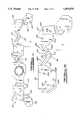
- FIG. 5is a rear perspective view of a partially assembled automotive instrument cluster containing the circuit board of the present invention.
- FIG. 6is a rear perspective view of a gauge commonly used in automotive instrument clusters.
- FIG. 7is a rear elevation view of the partially assembled automotive instrument cluster of FIG. 5.
- FIG. 1shows a circuit board 10 according to this invention.
- the circuit boardhas planar sections 20, 21, 22, 23, and 24, each section connected to another portion of the circuit board by springs 30, 31, 32, 33, 34, 35, and 36.
- FIG. 2shows an enlargement of a part of FIG. 1, showing sections 22 and 23 and springs 34 and 35 in greater detail.
- Sections 20, 21, 22, 23, and 24 of circuit board 10include holes for attaching gauges to the sections.
- section 22has four holes 221, 222, 223, and 224 through which terminals of a gauge can pass for attachment of the gauge to the circuit board.
- Section 23similarly contains holes 231, 232, 233 and 234.
- springs 30, 31, 32, 33, 34, 35, and 36are composed of two or more beams.
- spring 34is composed of beams 341 and 342 and spring 35 is composed of beams 351 and 352.
- the beamsare joined at an angle such that the beams are not collinear.
- the springs thus formedcan flex. This allows the sections connected by the springs to be moved in relation to one another and in relation to the rest of the circuit board in the two orthogonal axes designated "x" and "y" in FIGS. 1 and 2.
- circuit board 10is made of fiberglass circuit board material, one of the materials commonly known in the art as “hard” circuit board material. (Circuit board material composed of paper, epoxy, fiberglass, or composites of those materials is commonly called “hard” circuit board material).
- the springs provided by the inventionallow flexibility of circuit board 10 while maintaining the advantages of hard circuit board material. Those advantages include low cost and high durability.
- circuit board 10 of FIG. 1When fiberglass circuit board material is used, a very advantageous way of fabricating circuit board 10 of FIG. 1 is by stamping. If this method of fabricating circuit board 10 is chosen, the width of the beams should be at least twice the thickness of the circuit board. This allows circuit board 10 to survive the stamping process without breaking. Note, however, that this requirement applies if circuit board 10 is fabricated by stamping. If other methods of fabricating circuit board 10 are employed, this requirement does not necessarily apply.
- FR-4fiberglass circuit board material widely used in automotive applications. This type of material comes in standard thickness of approximately 1.5 millimeters. Therefore, if circuit board 10 depicted in FIG. 1 were fabricated by stamping from FR-4 circuit board material, the beams would be approximately 1.5 millimeters thick and at least 3 millimeters wide. For maximum flexibility, this lower limit of approximately 3 millimeters would ideally be used.
- FIG. 2illustrates two such notches 50 and 51. Note that in FIG. 1, all of the notches in circuit board 10 are located at the point of intersection of two beams (as are notches 50 and 51 in FIG. 2). However, removing the notches from anywhere in a beam provides added flexibility.
- FIG. 1Notice also in FIG. 1 that some sections are joined by multiple springs (for example, section 22 and section 23 are joined by springs 34 and 35). On the other hand, some sections are joined by a single spring (for example, section 20 and section 21 are joined by spring 30).
- the use of multiple springsprovides added strength (that is, greater resistance to breakage of the springs as they flex). The use of multiple springs, however, provides relatively less flexibility than the use of a single spring.
- FIGS. 3 and 4show alternate construction of the springs of the present invention. Note that in FIGS. 1 and 2, all of the springs 30, 31, 32, 33, 34, 35, and 36 are composed of two beams.
- Spring 37 in FIG. 3is composed of three beams, 371, 372, and 373.
- Springs 38 and 39 in FIG. 4are both composed of five beams.
- Spring 38is composed of beams 381, 382, 383, 384, and 385.
- Spring 39is composed of beams 391, 392, 393, 394, and 395.
- springs composed of a greater number of beamsfor example, three or five
- springs composed of a smaller number of beamsfor example, two).
- FIG. 5shows another embodiment of the present invention, an automotive instrument cluster 60, in a partially assembled configuration.
- Instrument cluster 60contains circuit board 10 of FIG. 1.
- instrument cluster 60contains a face portion 70, which is commonly called a face plate in the art.
- Instrument cluster 60further includes gauges 80, 81, 82, 83, and 84.
- Gauge 83representative of gauges 80, 81, 82, 83, and 84, is shown in FIG. 6.
- Gauge 83has terminals 835, 836, 837 and 838.
- Gauge 83further has holes 831 and 832 by which gauge 83 can be mounted with screws to face portion 70 of instrument cluster 60.
- gauge 83is attached to circuit board 10 by terminals 835, 836, 837, and 838 of gauge 83 going through holes 231, 232, 233, and 234 in section 23 of circuit board 10. Terminals 835, 836, 837, and 838 are then soldered to circuit board 10.
- Gauges 80, 81, 82, and 84are attached to circuit board 10 in a similar manner.
- Gauge 83is then mounted to face portion 70 of instrument cluster 60, by screws 91 and 92 through holes 831 and 832 in gauge 83 and into corresponding holes 71 and 72 in face portion 70.
- Gauges 80, 81, 82, and 84are mounted to face portion 70 in a similar manner.
- a final embodiment of the present inventionis a process for assembling an automotive instrument cluster. This process is illustrated with reference to FIG. 5.
- gauges 80, 81, 82, 83, and 84are attached to circuit board 10.
- Gauges 80, 81, 82, 83, and 84are then mounted to face plate 70 of instrument cluster 60.
- attaching gauges 80, 81, 82, 83, and 84 to circuit board 10fixes the relative positions of the gauges. Tolerance stack-ups make it highly unlikely that all of holes in all of the gauges (for instance, holes 831 and 832 in gauge 83) will then line up properly with all of the holes in face plate 70 (for instance, holes 71 and 72).
- the process of this embodiment of the inventionfurther comprises the step of moving sections 20, 21, 22, 23, and 24 as required so the holes in gauges 80, 81, 82, 83 and 84 line up with the holes in face plate 70.
- Gauges 80, 81, 82, 83 and 84are then mounted to face plate 70.
- circuit boardis an ideal choice as a material for circuit board 10 of FIG. 1.
- the inventioncan also be employed to advantage if other circuit board materials are used.
- the same advantageis gained whenever a circuit board of sufficient thickness as to be substantially not moveable in the x-y plane illustrated in FIG. 1 is employed.
- Sufficient thicknessis a function of the particular material used to make the circuit board.
Landscapes
- Engineering & Computer Science (AREA)
- Microelectronics & Electronic Packaging (AREA)
- Mechanical Engineering (AREA)
- Instrument Panels (AREA)
Abstract
Description
Claims (17)
Priority Applications (2)
| Application Number | Priority Date | Filing Date | Title |
|---|---|---|---|
| US08/136,843US5495076A (en) | 1993-10-18 | 1993-10-18 | Flexible geometry circuit board |
| CA002118142ACA2118142A1 (en) | 1993-10-18 | 1994-10-14 | Flexible geometry circuit board |
Applications Claiming Priority (1)
| Application Number | Priority Date | Filing Date | Title |
|---|---|---|---|
| US08/136,843US5495076A (en) | 1993-10-18 | 1993-10-18 | Flexible geometry circuit board |
Publications (1)
| Publication Number | Publication Date |
|---|---|
| US5495076Atrue US5495076A (en) | 1996-02-27 |
Family
ID=22474618
Family Applications (1)
| Application Number | Title | Priority Date | Filing Date |
|---|---|---|---|
| US08/136,843Expired - LifetimeUS5495076A (en) | 1993-10-18 | 1993-10-18 | Flexible geometry circuit board |
Country Status (2)
| Country | Link |
|---|---|
| US (1) | US5495076A (en) |
| CA (1) | CA2118142A1 (en) |
Cited By (24)
| Publication number | Priority date | Publication date | Assignee | Title |
|---|---|---|---|---|
| US5600100A (en)* | 1991-11-15 | 1997-02-04 | Itt Automotive Europe Gmbh | Electrical device, in particular steering column switch for automotive vehicles |
| WO1998028956A1 (en)* | 1996-12-20 | 1998-07-02 | Robert Bosch Gmbh | Conducting foil for conductively connecting electric and/or electronic components |
| US5777275A (en)* | 1995-09-25 | 1998-07-07 | Mitsubishi Denki Kabushiki Kaisha | Bendable circuit board having improved resistance to bending strain and increased element mounting area |
| US5903441A (en)* | 1997-09-24 | 1999-05-11 | Hewlett-Packard Company | Method and apparatus for aligning a printed circuit board with a chassis |
| US5959844A (en)* | 1993-09-25 | 1999-09-28 | Vdo Adolf Schindling Ag | Instrument cluster |
| US6126459A (en)* | 1997-03-24 | 2000-10-03 | Ford Motor Company | Substrate and electrical connector assembly |
| US6135586A (en)* | 1995-10-31 | 2000-10-24 | Hewlett-Packard Company | Large area inkjet printhead |
| EP1036712A3 (en)* | 1999-03-16 | 2001-07-11 | Volkswagen Aktiengesellschaft | Guide for cables and ducts in vehicle components and procedure for manufacturing a cables and ducts guide |
| DE20203577U1 (en) | 2002-03-06 | 2002-06-06 | Horst Siedle GmbH & Co. KG., 78120 Furtwangen | Carrier plate for electrical switching elements |
| US20050082866A1 (en)* | 2002-03-27 | 2005-04-21 | Faurecia Innenraum Systeme Gmbh | Device for retaining an instrument cluster and instrument panel |
| US20050092519A1 (en)* | 2003-11-05 | 2005-05-05 | Beauchamp John K. | Partially flexible circuit board |
| US20100122837A1 (en)* | 2008-11-20 | 2010-05-20 | Continental Automotive Gmbh | Circuit Board and Method of Producing a Circuit Board |
| US20110287660A1 (en)* | 2010-05-24 | 2011-11-24 | Hon Hai Precision Industry Co., Ltd. | Connecting member |
| EP2676829A1 (en)* | 2012-06-19 | 2013-12-25 | Johnson Controls Automotive Electronics SAS | Carrier assembly for an instrument cluster |
| US20140073152A1 (en)* | 2012-09-07 | 2014-03-13 | Apple Inc. | Conductive connections allowing xyz translation |
| US8840271B2 (en) | 2012-07-24 | 2014-09-23 | Abl Ip Holding Llc | In-plane bent printed circuit boards |
| WO2016046677A1 (en)* | 2014-09-23 | 2016-03-31 | Koninklijke Philips N.V. | Flat cable strain relief with controlled mechanical resistance |
| US9553385B2 (en)* | 2015-06-18 | 2017-01-24 | Dxo Labs | Electronic device comprising an electronic connector and a flexible printed circuit |
| US20170059140A1 (en)* | 2015-08-27 | 2017-03-02 | GE Lighting Solutions, LLC | Method and system for a three-dimensional (3-d) flexible light emitting diode (led) bar |
| EP3683914A1 (en)* | 2019-01-18 | 2020-07-22 | Samsung SDI Co., Ltd. | Circuit carrier for a battery system and battery system |
| US10973126B2 (en)* | 2016-05-26 | 2021-04-06 | Covidien Lp | Instrument drive units |
| WO2022147839A1 (en)* | 2021-01-11 | 2022-07-14 | 欧菲光集团股份有限公司 | Circuit board assembly, camera module, and electronic device |
| US11449108B2 (en)* | 2020-03-05 | 2022-09-20 | Microsoft Technology Licensing, Llc | Flexible hinge device |
| US11596059B2 (en) | 2019-01-18 | 2023-02-28 | Samsung Sdi Co., Ltd. | Circuit carrier for a battery system and battery system |
Citations (16)
| Publication number | Priority date | Publication date | Assignee | Title |
|---|---|---|---|---|
| DE1766162A1 (en)* | 1968-04-11 | 1969-10-16 | Siemens Ag | Assembly made up of a plurality of control modules for contactless control technology combined on a carrier (print) to form a functional unit |
| GB1287074A (en)* | 1971-01-28 | 1972-08-31 | Ford Motor Co | Electrical wiring harness |
| US3979763A (en)* | 1974-08-05 | 1976-09-07 | Polaroid Corporation | Circuit board arrangement for collapsible camera apparatus |
| US4191441A (en)* | 1978-02-24 | 1980-03-04 | Ford Motor Company | Circuit board assembly |
| US4359277A (en)* | 1976-05-24 | 1982-11-16 | Canon Kabushiki Kaisha | Camera with printed circuit boards comprising resistance-conductor laminated constructions |
| US4587719A (en)* | 1983-08-01 | 1986-05-13 | The Board Of Trustees Of The Leland Stanford Junior University | Method of fabrication of long arrays using a short substrate |
| US4974121A (en)* | 1987-05-29 | 1990-11-27 | Fuji Xerox Co., Ltd. | Wiring module |
| US4986870A (en)* | 1984-03-09 | 1991-01-22 | R.W.Q., Inc. | Apparatus for laminating multilayered printed circuit boards having both rigid and flexible portions |
| US5008496A (en)* | 1988-09-15 | 1991-04-16 | Siemens Aktiengesellschaft | Three-dimensional printed circuit board |
| US5032737A (en)* | 1990-07-24 | 1991-07-16 | Deere & Company | Ignition circuit module and method of manufacture |
| US5121297A (en)* | 1990-12-31 | 1992-06-09 | Compaq Computer Corporation | Flexible printed circuits |
| US5142448A (en)* | 1990-02-05 | 1992-08-25 | Horst Kober | Method for manufacturing rigid-flexible multilayer circuit boards and products thereof |
| JPH04246882A (en)* | 1991-02-01 | 1992-09-02 | Canon Inc | flexible printed circuit board |
| US5144742A (en)* | 1991-02-27 | 1992-09-08 | Zycon Corporation | Method of making rigid-flex printed circuit boards |
| US5250758A (en)* | 1991-05-21 | 1993-10-05 | Elf Technologies, Inc. | Methods and systems of preparing extended length flexible harnesses |
| US5357065A (en)* | 1992-07-10 | 1994-10-18 | Fujitsu Limited | Circuit unit for electronic instrument having key-pad arrangement |
- 1993
- 1993-10-18USUS08/136,843patent/US5495076A/ennot_activeExpired - Lifetime
- 1994
- 1994-10-14CACA002118142Apatent/CA2118142A1/ennot_activeAbandoned
Patent Citations (16)
| Publication number | Priority date | Publication date | Assignee | Title |
|---|---|---|---|---|
| DE1766162A1 (en)* | 1968-04-11 | 1969-10-16 | Siemens Ag | Assembly made up of a plurality of control modules for contactless control technology combined on a carrier (print) to form a functional unit |
| GB1287074A (en)* | 1971-01-28 | 1972-08-31 | Ford Motor Co | Electrical wiring harness |
| US3979763A (en)* | 1974-08-05 | 1976-09-07 | Polaroid Corporation | Circuit board arrangement for collapsible camera apparatus |
| US4359277A (en)* | 1976-05-24 | 1982-11-16 | Canon Kabushiki Kaisha | Camera with printed circuit boards comprising resistance-conductor laminated constructions |
| US4191441A (en)* | 1978-02-24 | 1980-03-04 | Ford Motor Company | Circuit board assembly |
| US4587719A (en)* | 1983-08-01 | 1986-05-13 | The Board Of Trustees Of The Leland Stanford Junior University | Method of fabrication of long arrays using a short substrate |
| US4986870A (en)* | 1984-03-09 | 1991-01-22 | R.W.Q., Inc. | Apparatus for laminating multilayered printed circuit boards having both rigid and flexible portions |
| US4974121A (en)* | 1987-05-29 | 1990-11-27 | Fuji Xerox Co., Ltd. | Wiring module |
| US5008496A (en)* | 1988-09-15 | 1991-04-16 | Siemens Aktiengesellschaft | Three-dimensional printed circuit board |
| US5142448A (en)* | 1990-02-05 | 1992-08-25 | Horst Kober | Method for manufacturing rigid-flexible multilayer circuit boards and products thereof |
| US5032737A (en)* | 1990-07-24 | 1991-07-16 | Deere & Company | Ignition circuit module and method of manufacture |
| US5121297A (en)* | 1990-12-31 | 1992-06-09 | Compaq Computer Corporation | Flexible printed circuits |
| JPH04246882A (en)* | 1991-02-01 | 1992-09-02 | Canon Inc | flexible printed circuit board |
| US5144742A (en)* | 1991-02-27 | 1992-09-08 | Zycon Corporation | Method of making rigid-flex printed circuit boards |
| US5250758A (en)* | 1991-05-21 | 1993-10-05 | Elf Technologies, Inc. | Methods and systems of preparing extended length flexible harnesses |
| US5357065A (en)* | 1992-07-10 | 1994-10-18 | Fujitsu Limited | Circuit unit for electronic instrument having key-pad arrangement |
Non-Patent Citations (2)
| Title |
|---|
| Abrasion Resistance (plus 8 more KEL F 81 virtues) helps fold miniaturization problems down to size Minnesota Mining & Manufacturing Co., Electronic Design, Aug. 2, 1962, p. 132.* |
| Abrasion Resistance (plus 8 more KEL-F® 81 virtues) helps fold miniaturization problems down to size? Minnesota Mining & Manufacturing Co., Electronic Design, Aug. 2, 1962, p. 132. |
Cited By (35)
| Publication number | Priority date | Publication date | Assignee | Title |
|---|---|---|---|---|
| US5600100A (en)* | 1991-11-15 | 1997-02-04 | Itt Automotive Europe Gmbh | Electrical device, in particular steering column switch for automotive vehicles |
| US5959844A (en)* | 1993-09-25 | 1999-09-28 | Vdo Adolf Schindling Ag | Instrument cluster |
| US5777275A (en)* | 1995-09-25 | 1998-07-07 | Mitsubishi Denki Kabushiki Kaisha | Bendable circuit board having improved resistance to bending strain and increased element mounting area |
| US6135586A (en)* | 1995-10-31 | 2000-10-24 | Hewlett-Packard Company | Large area inkjet printhead |
| US6150614A (en)* | 1996-12-20 | 2000-11-21 | Robert Bosch Gmbh | Conducting foil for conductively connecting electric and/or electronic components |
| WO1998028956A1 (en)* | 1996-12-20 | 1998-07-02 | Robert Bosch Gmbh | Conducting foil for conductively connecting electric and/or electronic components |
| JP2000505952A (en)* | 1996-12-20 | 2000-05-16 | ローベルト ボツシユ ゲゼルシヤフト ミツト ベシユレンクテル ハフツング | Conductive sheet for conductively connecting electrical and / or electronic components |
| US6126459A (en)* | 1997-03-24 | 2000-10-03 | Ford Motor Company | Substrate and electrical connector assembly |
| US5903441A (en)* | 1997-09-24 | 1999-05-11 | Hewlett-Packard Company | Method and apparatus for aligning a printed circuit board with a chassis |
| EP1036712A3 (en)* | 1999-03-16 | 2001-07-11 | Volkswagen Aktiengesellschaft | Guide for cables and ducts in vehicle components and procedure for manufacturing a cables and ducts guide |
| DE20203577U1 (en) | 2002-03-06 | 2002-06-06 | Horst Siedle GmbH & Co. KG., 78120 Furtwangen | Carrier plate for electrical switching elements |
| US20050082866A1 (en)* | 2002-03-27 | 2005-04-21 | Faurecia Innenraum Systeme Gmbh | Device for retaining an instrument cluster and instrument panel |
| US6971701B2 (en)* | 2002-03-27 | 2005-12-06 | Faurecia Innenraum Systeme Gmbh | Device for retaining an instrument cluster and instrument panel |
| US20050092519A1 (en)* | 2003-11-05 | 2005-05-05 | Beauchamp John K. | Partially flexible circuit board |
| US8294033B2 (en)* | 2008-11-20 | 2012-10-23 | Continental Automotive Gmbh | Circuit board and method of producing a circuit board |
| US20100122837A1 (en)* | 2008-11-20 | 2010-05-20 | Continental Automotive Gmbh | Circuit Board and Method of Producing a Circuit Board |
| US20110287660A1 (en)* | 2010-05-24 | 2011-11-24 | Hon Hai Precision Industry Co., Ltd. | Connecting member |
| US8383942B2 (en)* | 2010-05-24 | 2013-02-26 | Hon Hai Precision Industry Co., Ltd. | Connecting member |
| EP2676829A1 (en)* | 2012-06-19 | 2013-12-25 | Johnson Controls Automotive Electronics SAS | Carrier assembly for an instrument cluster |
| US8840271B2 (en) | 2012-07-24 | 2014-09-23 | Abl Ip Holding Llc | In-plane bent printed circuit boards |
| US20140073152A1 (en)* | 2012-09-07 | 2014-03-13 | Apple Inc. | Conductive connections allowing xyz translation |
| US8895865B2 (en)* | 2012-09-07 | 2014-11-25 | Conor P. Lenahan | Conductive connections allowing XYZ translation |
| CN107006117A (en)* | 2014-09-23 | 2017-08-01 | 皇家飞利浦有限公司 | Flat cable strain relief with controlled mechanical resistance |
| WO2016046677A1 (en)* | 2014-09-23 | 2016-03-31 | Koninklijke Philips N.V. | Flat cable strain relief with controlled mechanical resistance |
| RU2692486C2 (en)* | 2014-09-23 | 2019-06-25 | Конинклейке Филипс Н.В. | Unloading from tension of flat cable by means of controlled mechanical resistance |
| US9553385B2 (en)* | 2015-06-18 | 2017-01-24 | Dxo Labs | Electronic device comprising an electronic connector and a flexible printed circuit |
| US20170059140A1 (en)* | 2015-08-27 | 2017-03-02 | GE Lighting Solutions, LLC | Method and system for a three-dimensional (3-d) flexible light emitting diode (led) bar |
| US10222036B2 (en)* | 2015-08-27 | 2019-03-05 | GE Lighting Solutions, LLC | Method and system for a three-dimensional (3-D) flexible light emitting diode (LED) bar |
| US10973126B2 (en)* | 2016-05-26 | 2021-04-06 | Covidien Lp | Instrument drive units |
| US11523509B2 (en) | 2016-05-26 | 2022-12-06 | Covidien Lp | Instrument drive units |
| EP3683914A1 (en)* | 2019-01-18 | 2020-07-22 | Samsung SDI Co., Ltd. | Circuit carrier for a battery system and battery system |
| KR20200090627A (en)* | 2019-01-18 | 2020-07-29 | 삼성에스디아이 주식회사 | Circuit carrier for battery system and battery system |
| US11596059B2 (en) | 2019-01-18 | 2023-02-28 | Samsung Sdi Co., Ltd. | Circuit carrier for a battery system and battery system |
| US11449108B2 (en)* | 2020-03-05 | 2022-09-20 | Microsoft Technology Licensing, Llc | Flexible hinge device |
| WO2022147839A1 (en)* | 2021-01-11 | 2022-07-14 | 欧菲光集团股份有限公司 | Circuit board assembly, camera module, and electronic device |
Also Published As
| Publication number | Publication date |
|---|---|
| CA2118142A1 (en) | 1995-04-19 |
Similar Documents
| Publication | Publication Date | Title |
|---|---|---|
| US5495076A (en) | Flexible geometry circuit board | |
| US5527187A (en) | Compliant electrical interconnect | |
| US6016253A (en) | Electronic module | |
| US6358065B1 (en) | Display unit installing and connecting device | |
| US4360858A (en) | Instrument panel assembly with conductive elastomeric connectors | |
| US5325081A (en) | Supported strain gauge and joy stick assembly and method of making | |
| US7529104B2 (en) | Conduction device | |
| US5397239A (en) | Molded hinged connector | |
| US6220881B1 (en) | Card edge connector | |
| US5131874A (en) | Female contact in a connector | |
| US7331798B2 (en) | Connecting element and circuit connecting device using the connecting element | |
| US10541485B2 (en) | On-board diagnostic system and terminal and manufacturing method thereof | |
| US20210022246A1 (en) | Method for manufacturing flexible printed circuit terminal connection structures | |
| JP3989696B2 (en) | connector | |
| US5161982A (en) | Reactive base for cantilevered connector | |
| JP2003045525A (en) | Connector | |
| JP2000148383A (en) | Input device | |
| JP3061328B2 (en) | Contact connector | |
| JP3128568B2 (en) | Mounting structure of electrical connector and jig used for mounting | |
| US12225664B2 (en) | Circuit board assembly | |
| JP2923522B2 (en) | Flexible wiring board and its manufacturing method | |
| JP3136123B2 (en) | Electronic components | |
| JP3252247B2 (en) | Card edge connector | |
| JP3118492B2 (en) | Terminal structure and high-voltage electronic component having the terminal structure | |
| JPH0411351Y2 (en) |
Legal Events
| Date | Code | Title | Description |
|---|---|---|---|
| AS | Assignment | Owner name:FORD MOTOR COMPANY, MICHIGAN Free format text:ASSIGNMENT OF ASSIGNORS INTEREST;ASSIGNOR:DAVIS, MICHAEL SCOTT;REEL/FRAME:007022/0905 Effective date:19931013 | |
| STCF | Information on status: patent grant | Free format text:PATENTED CASE | |
| FPAY | Fee payment | Year of fee payment:4 | |
| AS | Assignment | Owner name:VISTEON GLOBAL TECHNOLOGIES, INC., MICHIGAN Free format text:ASSIGNMENT OF ASSIGNORS INTEREST;ASSIGNOR:FORD MOTOR COMPANY;REEL/FRAME:010968/0220 Effective date:20000615 | |
| FPAY | Fee payment | Year of fee payment:8 | |
| FPAY | Fee payment | Year of fee payment:12 | |
| AS | Assignment | Owner name:JPMORGAN CHASE BANK, N.A., AS ADMINISTRATIVE AGENT Free format text:SECURITY AGREEMENT;ASSIGNOR:VISTEON GLOBAL TECHNOLOGIES, INC.;REEL/FRAME:020497/0733 Effective date:20060613 | |
| AS | Assignment | Owner name:JPMORGAN CHASE BANK, TEXAS Free format text:SECURITY INTEREST;ASSIGNOR:VISTEON GLOBAL TECHNOLOGIES, INC.;REEL/FRAME:022368/0001 Effective date:20060814 Owner name:JPMORGAN CHASE BANK,TEXAS Free format text:SECURITY INTEREST;ASSIGNOR:VISTEON GLOBAL TECHNOLOGIES, INC.;REEL/FRAME:022368/0001 Effective date:20060814 | |
| AS | Assignment | Owner name:WILMINGTON TRUST FSB, AS ADMINISTRATIVE AGENT, MIN Free format text:ASSIGNMENT OF SECURITY INTEREST IN PATENTS;ASSIGNOR:JPMORGAN CHASE BANK, N.A., AS ADMINISTRATIVE AGENT;REEL/FRAME:022575/0186 Effective date:20090415 Owner name:WILMINGTON TRUST FSB, AS ADMINISTRATIVE AGENT,MINN Free format text:ASSIGNMENT OF SECURITY INTEREST IN PATENTS;ASSIGNOR:JPMORGAN CHASE BANK, N.A., AS ADMINISTRATIVE AGENT;REEL/FRAME:022575/0186 Effective date:20090415 | |
| AS | Assignment | Owner name:THE BANK OF NEW YORK MELLON, AS ADMINISTRATIVE AGE Free format text:ASSIGNMENT OF PATENT SECURITY INTEREST;ASSIGNOR:JPMORGAN CHASE BANK, N.A., A NATIONAL BANKING ASSOCIATION;REEL/FRAME:022974/0057 Effective date:20090715 | |
| AS | Assignment | Owner name:VISTEON GLOBAL TECHNOLOGIES, INC., MICHIGAN Free format text:RELEASE BY SECURED PARTY AGAINST SECURITY INTEREST IN PATENTS RECORDED AT REEL 022974 FRAME 0057;ASSIGNOR:THE BANK OF NEW YORK MELLON;REEL/FRAME:025095/0711 Effective date:20101001 | |
| AS | Assignment | Owner name:VISTEON GLOBAL TECHNOLOGIES, INC., MICHIGAN Free format text:RELEASE BY SECURED PARTY AGAINST SECURITY INTEREST IN PATENTS RECORDED AT REEL 022575 FRAME 0186;ASSIGNOR:WILMINGTON TRUST FSB, AS ADMINISTRATIVE AGENT;REEL/FRAME:025105/0201 Effective date:20101001 | |
| AS | Assignment | Owner name:MORGAN STANLEY SENIOR FUNDING, INC., AS AGENT, NEW Free format text:SECURITY AGREEMENT (REVOLVER);ASSIGNORS:VISTEON CORPORATION;VC AVIATION SERVICES, LLC;VISTEON ELECTRONICS CORPORATION;AND OTHERS;REEL/FRAME:025238/0298 Effective date:20101001 Owner name:MORGAN STANLEY SENIOR FUNDING, INC., AS AGENT, NEW Free format text:SECURITY AGREEMENT;ASSIGNORS:VISTEON CORPORATION;VC AVIATION SERVICES, LLC;VISTEON ELECTRONICS CORPORATION;AND OTHERS;REEL/FRAME:025241/0317 Effective date:20101007 | |
| AS | Assignment | Owner name:VISTEON ELECTRONICS CORPORATION, MICHIGAN Free format text:RELEASE BY SECURED PARTY AGAINST SECURITY INTEREST IN PATENTS ON REEL 025241 FRAME 0317;ASSIGNOR:MORGAN STANLEY SENIOR FUNDING, INC.;REEL/FRAME:026178/0412 Effective date:20110406 Owner name:VISTEON GLOBAL TREASURY, INC., MICHIGAN Free format text:RELEASE BY SECURED PARTY AGAINST SECURITY INTEREST IN PATENTS ON REEL 025241 FRAME 0317;ASSIGNOR:MORGAN STANLEY SENIOR FUNDING, INC.;REEL/FRAME:026178/0412 Effective date:20110406 Owner name:VISTEON INTERNATIONAL HOLDINGS, INC., MICHIGAN Free format text:RELEASE BY SECURED PARTY AGAINST SECURITY INTEREST IN PATENTS ON REEL 025241 FRAME 0317;ASSIGNOR:MORGAN STANLEY SENIOR FUNDING, INC.;REEL/FRAME:026178/0412 Effective date:20110406 Owner name:VISTEON INTERNATIONAL BUSINESS DEVELOPMENT, INC., Free format text:RELEASE BY SECURED PARTY AGAINST SECURITY INTEREST IN PATENTS ON REEL 025241 FRAME 0317;ASSIGNOR:MORGAN STANLEY SENIOR FUNDING, INC.;REEL/FRAME:026178/0412 Effective date:20110406 Owner name:VISTEON EUROPEAN HOLDING, INC., MICHIGAN Free format text:RELEASE BY SECURED PARTY AGAINST SECURITY INTEREST IN PATENTS ON REEL 025241 FRAME 0317;ASSIGNOR:MORGAN STANLEY SENIOR FUNDING, INC.;REEL/FRAME:026178/0412 Effective date:20110406 Owner name:VISTEON GLOBAL TECHNOLOGIES, INC., MICHIGAN Free format text:RELEASE BY SECURED PARTY AGAINST SECURITY INTEREST IN PATENTS ON REEL 025241 FRAME 0317;ASSIGNOR:MORGAN STANLEY SENIOR FUNDING, INC.;REEL/FRAME:026178/0412 Effective date:20110406 Owner name:VISTEON CORPORATION, MICHIGAN Free format text:RELEASE BY SECURED PARTY AGAINST SECURITY INTEREST IN PATENTS ON REEL 025241 FRAME 0317;ASSIGNOR:MORGAN STANLEY SENIOR FUNDING, INC.;REEL/FRAME:026178/0412 Effective date:20110406 Owner name:VC AVIATION SERVICES, LLC, MICHIGAN Free format text:RELEASE BY SECURED PARTY AGAINST SECURITY INTEREST IN PATENTS ON REEL 025241 FRAME 0317;ASSIGNOR:MORGAN STANLEY SENIOR FUNDING, INC.;REEL/FRAME:026178/0412 Effective date:20110406 Owner name:VISTEON SYSTEMS, LLC, MICHIGAN Free format text:RELEASE BY SECURED PARTY AGAINST SECURITY INTEREST IN PATENTS ON REEL 025241 FRAME 0317;ASSIGNOR:MORGAN STANLEY SENIOR FUNDING, INC.;REEL/FRAME:026178/0412 Effective date:20110406 | |
| AS | Assignment | Owner name:VISTEON GLOBAL TECHNOLOGIES, INC., MICHIGAN Free format text:RELEASE OF SECURITY INTEREST IN INTELLECTUAL PROPERTY;ASSIGNOR:MORGAN STANLEY SENIOR FUNDING, INC.;REEL/FRAME:033107/0717 Effective date:20140409 Owner name:VISTEON EUROPEAN HOLDINGS, INC., MICHIGAN Free format text:RELEASE OF SECURITY INTEREST IN INTELLECTUAL PROPERTY;ASSIGNOR:MORGAN STANLEY SENIOR FUNDING, INC.;REEL/FRAME:033107/0717 Effective date:20140409 Owner name:VISTEON INTERNATIONAL HOLDINGS, INC., MICHIGAN Free format text:RELEASE OF SECURITY INTEREST IN INTELLECTUAL PROPERTY;ASSIGNOR:MORGAN STANLEY SENIOR FUNDING, INC.;REEL/FRAME:033107/0717 Effective date:20140409 Owner name:VISTEON CORPORATION, MICHIGAN Free format text:RELEASE OF SECURITY INTEREST IN INTELLECTUAL PROPERTY;ASSIGNOR:MORGAN STANLEY SENIOR FUNDING, INC.;REEL/FRAME:033107/0717 Effective date:20140409 Owner name:VISTEON ELECTRONICS CORPORATION, MICHIGAN Free format text:RELEASE OF SECURITY INTEREST IN INTELLECTUAL PROPERTY;ASSIGNOR:MORGAN STANLEY SENIOR FUNDING, INC.;REEL/FRAME:033107/0717 Effective date:20140409 Owner name:VC AVIATION SERVICES, LLC, MICHIGAN Free format text:RELEASE OF SECURITY INTEREST IN INTELLECTUAL PROPERTY;ASSIGNOR:MORGAN STANLEY SENIOR FUNDING, INC.;REEL/FRAME:033107/0717 Effective date:20140409 Owner name:VISTEON SYSTEMS, LLC, MICHIGAN Free format text:RELEASE OF SECURITY INTEREST IN INTELLECTUAL PROPERTY;ASSIGNOR:MORGAN STANLEY SENIOR FUNDING, INC.;REEL/FRAME:033107/0717 Effective date:20140409 Owner name:VISTEON INTERNATIONAL BUSINESS DEVELOPMENT, INC., Free format text:RELEASE OF SECURITY INTEREST IN INTELLECTUAL PROPERTY;ASSIGNOR:MORGAN STANLEY SENIOR FUNDING, INC.;REEL/FRAME:033107/0717 Effective date:20140409 Owner name:VISTEON GLOBAL TREASURY, INC., MICHIGAN Free format text:RELEASE OF SECURITY INTEREST IN INTELLECTUAL PROPERTY;ASSIGNOR:MORGAN STANLEY SENIOR FUNDING, INC.;REEL/FRAME:033107/0717 Effective date:20140409 |