US5494798A - Fiber optic evanscent wave sensor for immunoassay - Google Patents
Fiber optic evanscent wave sensor for immunoassayDownload PDFInfo
- Publication number
- US5494798A US5494798AUS08/163,709US16370993AUS5494798AUS 5494798 AUS5494798 AUS 5494798AUS 16370993 AUS16370993 AUS 16370993AUS 5494798 AUS5494798 AUS 5494798A
- Authority
- US
- United States
- Prior art keywords
- coupler
- fiber optic
- immunoassay
- light
- target
- Prior art date
- Legal status (The legal status is an assumption and is not a legal conclusion. Google has not performed a legal analysis and makes no representation as to the accuracy of the status listed.)
- Expired - Fee Related
Links
- 239000000835fiberSubstances0.000titleclaimsabstractdescription92
- 238000003018immunoassayMethods0.000titleclaimsabstractdescription26
- 230000004927fusionEffects0.000claimsabstractdescription22
- 230000008859changeEffects0.000claimsabstractdescription14
- 239000000427antigenSubstances0.000claimsdescription31
- 108091007433antigensProteins0.000claimsdescription30
- 102000036639antigensHuman genes0.000claimsdescription30
- 230000027455bindingEffects0.000claimsdescription23
- 238000009739bindingMethods0.000claimsdescription23
- 239000013307optical fiberSubstances0.000claimsdescription22
- 230000003287optical effectEffects0.000claimsdescription21
- 238000000034methodMethods0.000claimsdescription14
- 238000005259measurementMethods0.000claimsdescription12
- 239000012491analyteSubstances0.000claimsdescription10
- 108020004414DNAProteins0.000claimsdescription7
- 239000011248coating agentSubstances0.000claimsdescription7
- 238000000576coating methodMethods0.000claimsdescription7
- 150000007523nucleic acidsChemical group0.000claimsdescription6
- 108091034117OligonucleotideProteins0.000claimsdescription5
- 239000003153chemical reaction reagentSubstances0.000claimsdescription5
- 239000000463materialSubstances0.000claimsdescription5
- 239000002299complementary DNASubstances0.000claimsdescription4
- 230000001427coherent effectEffects0.000claimsdescription2
- 238000009396hybridizationMethods0.000claimsdescription2
- 239000012530fluidSubstances0.000claims7
- 108091028043Nucleic acid sequenceProteins0.000claims5
- 230000009870specific bindingEffects0.000claims4
- 230000000692anti-sense effectEffects0.000claims1
- 230000003100immobilizing effectEffects0.000claims1
- 238000007899nucleic acid hybridizationMethods0.000claims1
- 239000013077target materialSubstances0.000claims1
- 239000000126substanceSubstances0.000abstractdescription8
- 230000003993interactionEffects0.000abstractdescription4
- 230000000694effectsEffects0.000abstractdescription3
- 238000005253claddingMethods0.000description12
- 239000004020conductorSubstances0.000description7
- 230000008878couplingEffects0.000description7
- 238000010168coupling processMethods0.000description7
- 238000005859coupling reactionMethods0.000description7
- 230000035945sensitivityEffects0.000description7
- 108091032973(ribonucleotides)n+mProteins0.000description5
- 238000010521absorption reactionMethods0.000description5
- 238000001514detection methodMethods0.000description5
- 230000008901benefitEffects0.000description4
- 238000010586diagramMethods0.000description4
- 239000003446ligandSubstances0.000description4
- 239000000243solutionSubstances0.000description4
- 108020004635Complementary DNAProteins0.000description3
- VYPSYNLAJGMNEJ-UHFFFAOYSA-NSilicium dioxideChemical groupO=[Si]=OVYPSYNLAJGMNEJ-UHFFFAOYSA-N0.000description3
- 238000003556assayMethods0.000description3
- 238000010276constructionMethods0.000description3
- 239000011521glassSubstances0.000description3
- 238000004519manufacturing processMethods0.000description3
- 239000002773nucleotideSubstances0.000description3
- 125000003729nucleotide groupChemical group0.000description3
- 229920003229poly(methyl methacrylate)Polymers0.000description3
- 239000004926polymethyl methacrylateSubstances0.000description3
- 230000008569processEffects0.000description3
- 239000000523sampleSubstances0.000description3
- 238000001210attenuated total reflectance infrared spectroscopyMethods0.000description2
- 230000003247decreasing effectEffects0.000description2
- 229920006240drawn fiberPolymers0.000description2
- 238000005516engineering processMethods0.000description2
- 230000014509gene expressionEffects0.000description2
- 239000004033plasticSubstances0.000description2
- 229920003023plasticPolymers0.000description2
- 238000012545processingMethods0.000description2
- 239000007787solidSubstances0.000description2
- 238000004611spectroscopical analysisMethods0.000description2
- 238000012360testing methodMethods0.000description2
- JBRZTFJDHDCESZ-UHFFFAOYSA-NAsGaChemical compound[As]#[Ga]JBRZTFJDHDCESZ-UHFFFAOYSA-N0.000description1
- 102000053602DNAHuman genes0.000description1
- YCKRFDGAMUMZLT-UHFFFAOYSA-NFluorine atomChemical compound[F]YCKRFDGAMUMZLT-UHFFFAOYSA-N0.000description1
- 102000003886GlycoproteinsHuman genes0.000description1
- 108090000288GlycoproteinsProteins0.000description1
- XUIMIQQOPSSXEZ-UHFFFAOYSA-NSiliconChemical compound[Si]XUIMIQQOPSSXEZ-UHFFFAOYSA-N0.000description1
- JLCPHMBAVCMARE-UHFFFAOYSA-N[3-[[3-[[3-[[3-[[3-[[3-[[3-[[3-[[3-[[3-[[3-[[5-(2-amino-6-oxo-1H-purin-9-yl)-3-[[3-[[3-[[3-[[3-[[3-[[5-(2-amino-6-oxo-1H-purin-9-yl)-3-[[5-(2-amino-6-oxo-1H-purin-9-yl)-3-hydroxyoxolan-2-yl]methoxy-hydroxyphosphoryl]oxyoxolan-2-yl]methoxy-hydroxyphosphoryl]oxy-5-(5-methyl-2,4-dioxopyrimidin-1-yl)oxolan-2-yl]methoxy-hydroxyphosphoryl]oxy-5-(6-aminopurin-9-yl)oxolan-2-yl]methoxy-hydroxyphosphoryl]oxy-5-(6-aminopurin-9-yl)oxolan-2-yl]methoxy-hydroxyphosphoryl]oxy-5-(6-aminopurin-9-yl)oxolan-2-yl]methoxy-hydroxyphosphoryl]oxy-5-(6-aminopurin-9-yl)oxolan-2-yl]methoxy-hydroxyphosphoryl]oxyoxolan-2-yl]methoxy-hydroxyphosphoryl]oxy-5-(5-methyl-2,4-dioxopyrimidin-1-yl)oxolan-2-yl]methoxy-hydroxyphosphoryl]oxy-5-(4-amino-2-oxopyrimidin-1-yl)oxolan-2-yl]methoxy-hydroxyphosphoryl]oxy-5-(5-methyl-2,4-dioxopyrimidin-1-yl)oxolan-2-yl]methoxy-hydroxyphosphoryl]oxy-5-(5-methyl-2,4-dioxopyrimidin-1-yl)oxolan-2-yl]methoxy-hydroxyphosphoryl]oxy-5-(6-aminopurin-9-yl)oxolan-2-yl]methoxy-hydroxyphosphoryl]oxy-5-(6-aminopurin-9-yl)oxolan-2-yl]methoxy-hydroxyphosphoryl]oxy-5-(4-amino-2-oxopyrimidin-1-yl)oxolan-2-yl]methoxy-hydroxyphosphoryl]oxy-5-(4-amino-2-oxopyrimidin-1-yl)oxolan-2-yl]methoxy-hydroxyphosphoryl]oxy-5-(4-amino-2-oxopyrimidin-1-yl)oxolan-2-yl]methoxy-hydroxyphosphoryl]oxy-5-(6-aminopurin-9-yl)oxolan-2-yl]methoxy-hydroxyphosphoryl]oxy-5-(4-amino-2-oxopyrimidin-1-yl)oxolan-2-yl]methyl [5-(6-aminopurin-9-yl)-2-(hydroxymethyl)oxolan-3-yl] hydrogen phosphatePolymersCc1cn(C2CC(OP(O)(=O)OCC3OC(CC3OP(O)(=O)OCC3OC(CC3O)n3cnc4c3nc(N)[nH]c4=O)n3cnc4c3nc(N)[nH]c4=O)C(COP(O)(=O)OC3CC(OC3COP(O)(=O)OC3CC(OC3COP(O)(=O)OC3CC(OC3COP(O)(=O)OC3CC(OC3COP(O)(=O)OC3CC(OC3COP(O)(=O)OC3CC(OC3COP(O)(=O)OC3CC(OC3COP(O)(=O)OC3CC(OC3COP(O)(=O)OC3CC(OC3COP(O)(=O)OC3CC(OC3COP(O)(=O)OC3CC(OC3COP(O)(=O)OC3CC(OC3COP(O)(=O)OC3CC(OC3COP(O)(=O)OC3CC(OC3COP(O)(=O)OC3CC(OC3COP(O)(=O)OC3CC(OC3COP(O)(=O)OC3CC(OC3CO)n3cnc4c(N)ncnc34)n3ccc(N)nc3=O)n3cnc4c(N)ncnc34)n3ccc(N)nc3=O)n3ccc(N)nc3=O)n3ccc(N)nc3=O)n3cnc4c(N)ncnc34)n3cnc4c(N)ncnc34)n3cc(C)c(=O)[nH]c3=O)n3cc(C)c(=O)[nH]c3=O)n3ccc(N)nc3=O)n3cc(C)c(=O)[nH]c3=O)n3cnc4c3nc(N)[nH]c4=O)n3cnc4c(N)ncnc34)n3cnc4c(N)ncnc34)n3cnc4c(N)ncnc34)n3cnc4c(N)ncnc34)O2)c(=O)[nH]c1=OJLCPHMBAVCMARE-UHFFFAOYSA-N0.000description1
- 230000000890antigenic effectEffects0.000description1
- 238000013459approachMethods0.000description1
- 239000011230binding agentSubstances0.000description1
- 239000012620biological materialSubstances0.000description1
- 238000006243chemical reactionMethods0.000description1
- 239000013626chemical specieSubstances0.000description1
- 238000004891communicationMethods0.000description1
- 230000000295complement effectEffects0.000description1
- 230000021615conjugationEffects0.000description1
- 230000007423decreaseEffects0.000description1
- 238000011161developmentMethods0.000description1
- 201000010099diseaseDiseases0.000description1
- 208000037265diseases, disorders, signs and symptomsDiseases0.000description1
- 238000009826distributionMethods0.000description1
- 230000009977dual effectEffects0.000description1
- -1e.g.Proteins0.000description1
- 230000007613environmental effectEffects0.000description1
- 238000011156evaluationMethods0.000description1
- 230000002349favourable effectEffects0.000description1
- 229910052731fluorineInorganic materials0.000description1
- 239000011737fluorineSubstances0.000description1
- 239000005350fused silica glassSubstances0.000description1
- 230000002068genetic effectEffects0.000description1
- 229910052732germaniumInorganic materials0.000description1
- GNPVGFCGXDBREM-UHFFFAOYSA-Ngermanium atomChemical compound[Ge]GNPVGFCGXDBREM-UHFFFAOYSA-N0.000description1
- 230000002163immunogenEffects0.000description1
- 239000012678infectious agentSubstances0.000description1
- 208000015181infectious diseaseDiseases0.000description1
- 230000031700light absorptionEffects0.000description1
- 108020004999messenger RNAProteins0.000description1
- 230000009149molecular bindingEffects0.000description1
- 238000012806monitoring deviceMethods0.000description1
- 108020004707nucleic acidsProteins0.000description1
- 102000039446nucleic acidsHuman genes0.000description1
- 239000012466permeateSubstances0.000description1
- 229920000642polymerPolymers0.000description1
- 230000001681protective effectEffects0.000description1
- 108090000623proteins and genesProteins0.000description1
- 102000004169proteins and genesHuman genes0.000description1
- 230000009467reductionEffects0.000description1
- 238000012552reviewMethods0.000description1
- 238000012216screeningMethods0.000description1
- 239000004065semiconductorSubstances0.000description1
- 238000000926separation methodMethods0.000description1
- 229910052710siliconInorganic materials0.000description1
- 239000010703siliconSubstances0.000description1
- 239000000377silicon dioxideSubstances0.000description1
- 238000001179sorption measurementMethods0.000description1
- 125000006850spacer groupChemical group0.000description1
- 230000000087stabilizing effectEffects0.000description1
- 238000002198surface plasmon resonance spectroscopyMethods0.000description1
- 239000012085test solutionSubstances0.000description1
- 239000003053toxinSubstances0.000description1
- 231100000765toxinToxicity0.000description1
- 108700012359toxinsProteins0.000description1
- 239000012780transparent materialSubstances0.000description1
- 201000008827tuberculosisDiseases0.000description1
- 230000003612virological effectEffects0.000description1
- 239000011782vitaminSubstances0.000description1
- 229940088594vitaminDrugs0.000description1
Images


Classifications
- G—PHYSICS
- G01—MEASURING; TESTING
- G01N—INVESTIGATING OR ANALYSING MATERIALS BY DETERMINING THEIR CHEMICAL OR PHYSICAL PROPERTIES
- G01N33/00—Investigating or analysing materials by specific methods not covered by groups G01N1/00 - G01N31/00
- G01N33/48—Biological material, e.g. blood, urine; Haemocytometers
- G01N33/50—Chemical analysis of biological material, e.g. blood, urine; Testing involving biospecific ligand binding methods; Immunological testing
- G01N33/53—Immunoassay; Biospecific binding assay; Materials therefor
- G01N33/543—Immunoassay; Biospecific binding assay; Materials therefor with an insoluble carrier for immobilising immunochemicals
- G01N33/54366—Apparatus specially adapted for solid-phase testing
- G01N33/54373—Apparatus specially adapted for solid-phase testing involving physiochemical end-point determination, e.g. wave-guides, FETS, gratings
- C—CHEMISTRY; METALLURGY
- C12—BIOCHEMISTRY; BEER; SPIRITS; WINE; VINEGAR; MICROBIOLOGY; ENZYMOLOGY; MUTATION OR GENETIC ENGINEERING
- C12Q—MEASURING OR TESTING PROCESSES INVOLVING ENZYMES, NUCLEIC ACIDS OR MICROORGANISMS; COMPOSITIONS OR TEST PAPERS THEREFOR; PROCESSES OF PREPARING SUCH COMPOSITIONS; CONDITION-RESPONSIVE CONTROL IN MICROBIOLOGICAL OR ENZYMOLOGICAL PROCESSES
- C12Q1/00—Measuring or testing processes involving enzymes, nucleic acids or microorganisms; Compositions therefor; Processes of preparing such compositions
- C12Q1/68—Measuring or testing processes involving enzymes, nucleic acids or microorganisms; Compositions therefor; Processes of preparing such compositions involving nucleic acids
- C12Q1/6813—Hybridisation assays
- C12Q1/6816—Hybridisation assays characterised by the detection means
- C12Q1/6825—Nucleic acid detection involving sensors
Definitions
- This inventionis in the field of immunoassay devices and methods where fiber optic sensors are used.
- Optical fiberconsists of transparent material such as glass or plastic. Most optical fiber is fused silica and most plastic fiber is polymethylmethacrylate (PMMA). All optical fiber consists of a core and cladding of which the core has higher refractive index than the cladding. The fiber structure guides light by the process of total internal reflection (TIR). In silica fibers the core is usually established through doping with Germanium. PMMA uses a Fluorine polymer coating as the cladding. Fibers fall into two basic types, single mode or multimode. In single mode fibers the core is very small, 5 to 10 microns in diameter, for instance. Multimode fibers have cores of 50 to several thousand microns and very small cladding (in the order of tens of microns).
- Single mode fibershave a large cladding (usually more than 50 microns) making the fiber diameter generally 125 microns.
- the purpose of the large cladding in single mode fibersis to protect and contain the evanescent field of the single mode which extends into the cladding for several microns and can contain more than 10 percent of the optical energy normally thought of as traveling only through the core. Another importance of this larger diameter cladding is so that the fibers are hot too small for handling.
- Fiber optic (FO) immunosensors for immunoassaysmay be classified as belonging to one of several categories.
- a fiberIn the first type of fiber optic immunoassay sensor, a fiber is stripped of its cladding. To date these types of FO sensors have all been multi-mode. The various modes strike the glass air interface and are totally internally reflected. Just on the other side of the interface, where the reflection occurs, the light exists for a short distance in the physical form of an evanescent field. If a monoclonal or polyclonal antibody is attached to this surface, the field permeates this layer of antibody molecule but, there is little or no absorption or other phenomena which would otherwise change the amount of the light contained within the fiber.
- the evanescent fieldcan cause the antigens to fluoresce causing an emittance which is optically detectable in a reduction in the light level or through collection of the fluorescence. In this way light energy is taken from the core through the evanescent field and is used to cause fluorescence. It is usually necessary to conjugate a fluorophore to the antigen to accomplish this application. If no antigen is bound, no fluorescent Output occurs. In some cases it is the unknown antigens which are attached and the antibodies are allowed to bind, assuming there is specificity to the fluorescent antibodies.
- the sensorcan detect antigens or antigens and can be bound and the biosensor used to detect the presence of antibody (as in a disease state such as following infection with HIV or tuberculosis).
- the fiber optic sensorcan possibly replace many other immunodiagnostic modalities currently available. By binding the antigen, the sensor can probe unknown antibody. By binding an antibody, the assay can detect specific antigenic toxins or other immunogenic targets. Thus an organism is suspected to have been producing as a result of contact with an infectious agent.
- the second type of fiber optic immunoasay sensoruses a coating deposited onto a fiber tip which may be illuminated with pulse which in turn induces fluorescence which is reflected back up the fiber and later detected.
- a beam splitter and possibly a filteris usually used to separate the pulses from the fluorescence.
- either antibody or antigen sensorsmay be constructed.
- tip and geometriesReview articles are available in Volume I and II of Fiber Optic Chemical Sensors and Biosensors, Otto S. Wolfbeis, ed., CRC Press, Boca Raton (1991). A specifically relevant article appears in Volume II, Vo-Dinh, et al., "Fiberoptics Immunosensors," Chapter 17, page 271-257.
- a third type of fiber optic immunoassay sensorinvolves a stripped fiber which has antibodies or antigens attached to the core-air interface.
- This sensorsee R. G. Heideman, et al., "Simple interferometer for the evanescent field refractive index sensing as a feasibility study for an immunosensor," Applied Optics, Vol. 20, No. 12, pages 1474-1749 (1991), is used as one leg of a fiber optic Mach-Zehnder interferometer.
- the binding of molecules to the surface during attachment of either antibody or antigensuffices to locally change the index of refraction at the core solution interface.
- the first type of fiber optic immunoasay sensorsare fiber optic variations of internal reflection spectroscopy technology and are thoroughly described in Internal Reflection Spectroscopy by N. J. Harrick, Harrick Scientific Corporation, Ossining, N.Y. (1987). Harrick describes all kinds of geometries for these multimode sensors.
- a reference for the theory of fiber opticsis Optical Wave Guide Theory by a W. Snyder and J. D. Love, Chapman and Hall, New York (1983). See also G. Stewart, et al., "Chemical sensing by evanescent field adsorption: the sensitivity of optical waveguides", “Proceedings of the international Society of Optical Engineering (SPIE)", Vol. 990, Boston,1988.
- the evanescent fieldextends for only about one optical wavelength beyond the actual fusion joint surface. For light of 830 nm wavelength, it is not necessary to coat the fibers to more than one micron in thickness.
- single mode fibersonly support the lowest order spatial mode and there is no speckle in these systems. Coupler sensors also are not subject to modal redistribution due to environmental effects. Another significant advantage of single mode fibers is that the evanescent field surrounds the entire space immediately surrounding the core. Couplers can locally force more than 90% of the optical energy into the evanescent field. It should be noted, however, that since single mode waveguides may not be analyzed using the ray optic approximation, electromagnetic waveguide theory must be applied.
- This inventionprovides a sensitive detector having a wide variety of applications in the fields of biology, biochemistry and chemistry, and in many clinical applications as well. It uses a fiber optic coupler output ratio change due to the chemical/biochemical/bioaffinity/immunogenic-type interaction of bio-molecules (ligands) with their respective binding partners.
- ligandsbio-molecules
- the terms ligand and its binding partner for the ligand or, simply, binderwill be used to represent the two components in specific bioaffinity binding pairs, all of which are capable of recognizing and binding with the other partner in a bimolecular recognition pair.
- binding pairsinclude: antigen-antibody, substrate-enzyme, effector-enzyme, inhibitor-enzyme, complementary nucleic acid strands, binding protein-vitamin, binding protein-nucleic acid; reactive dye-protein, reactive dye-nucleic acid; and others.
- Either of the bindings partnersis permanently attached to the fusion joint of a single mode coupler and within the evanescent field for very specific and direct detection of minute concentrations of an analyte of interest (one of the components of the binding pair) within the tested sample without the need to label a reagent.
- the biomoleculemay be linked to the surface of the fusion joint by means of a spacer molecule.
- This applicationhas potential uses in many areas: 1) the evaluation of levels of mRNA expression in tissues, e.g., the determination of tissue specificity of gene expression; 2) the detection of viral or other rare DNAs; 3) forensic science, paternity testing.
- the sensormay also substitute for Northern or Southern or Dot blots in some instances.
- Coupler sensors with a single modeshare the advantages of the conventional single mode sensors. However, absorption is not necessary and is not even desirable for the operation of the sensor. As the coupler output ratio is extremely sensitive to the refractive index of the medium which surrounds the fusion joint of the coupler, chemical changes occurring near the fusion joint will cause a trading of power between the output channels. Changes in refractive index of one part in a million have been measured with the simple hand-held optical power meters used in fiber optics communication systems.
- Coupler sensorsprovide a signal processing advantage which is important to the measurement of small signal changes. Since there is no signal lost to absorption, the two coupler output channels will sum to a constant level even though the coupling ratio may change drastically. The dual output provides a total separation of drift variables from sensor variables. Difference over sum signal processing is also available as are a number of attractive electronic methods common to self referenced systems. Thus in view of this consideration in the construction of antibody conjugated optical fiber couplers may provide useful probes for detecting soluble ligands and similarly, the construction of nucleotide sensors, with conjugate DNA or RNA, may provide improved methods for detection of complimentary DNA or RNA.
- coupler fabrication technologiesnow provide an electric furnace method of biconical coupler fabrication.
- a coupler fusion electric furnace taught by U.S. Pat. No. 4,879,454, Gerdt, (incorporated herein by reference)allows inexpensive production of single mode couplers.
- Coupler sensorscan be used in an assay method for very dilute, specific antigens, e.g., proteins including glycoproteins.
- the attachment of polyclonal antibodiescan be used as screening tests for one or more of several specific antigens.
- the coupler output ratiodepends very strongly on the refractive Small changes in index change greatly or even switch totally the division of optical power between the output fibers.
- a coupler-antibody systemcan be prepared with an antibody and then exposed to a test solution containing an antigen capable of binding with this antibody. Upon first contact the coupler output ratio will immediately change to a certain value. This value will remain constant if no specific antigens are present. As the reaction proceeds, the antigen capable of binding with the antibody, if present, will begin to bind to the antibody until the degree of binding reaches an equilibrium value after a few minutes. The binding will occur only within the evanescent field of the coupler where the output ratio of the coupler is determined. Binding changes dramatically the electronic distribution of the original fusion joint coating because the index of refraction depends almost entirely on electronic arrangement and densities.
- a coupler sensor used in this manneracts as an antibody immobilized on a solid support in an immunoassay.
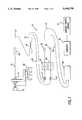
- FIG. 1is a flow diagram of an immunoassay system based upon a fiber optic coupler in accordance with this invention.
- FIG. 2shows a coupler joint, or a drawn fiber pair.
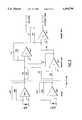
- FIG. 3shows a detailed diagram of the transimpedance amplifier and photo diodes used for producing the sum and difference signals referred to in FIG. 1.
- FIG. 4shows a sensitivity of an underdrawn coupler to the refractive index.
- FIG. 5shows the sensitive of a balanced (in air) coupler to refractive index.
- FIG. 6shows a sensitivity of an overdrawn coupler to refractive index.
- FIG. 7shows a representational sketch of a fiber optical coupler which has been prepared with antibodies attached and inserted into a solution containing antigens to form a coupler antibody system.
- FIG. 8shows a representational sketch of the joint of a coupler including the region of the evanescent field.
- FIG. 9shows a graph depicting the relationship of the strength of and evanescent field to distance from a coupler surface.
- FIG. 1there is shown an overall fiber optic system diagram 10 in accordance with this invention.
- a laser driver 12is connected to a laser diode 14, which is in turn, connected to a pig tail fiber 15 which passes light from the laser to a fiber optic splice 16.
- Light entering the first leg 17 of the coupler 18exits on the same fiber at a fiber optic conductor 19 (input channel).
- a second fiber optic output 20(output channel) provides an output for light from the first leg 17 which is coupled and inserted into a fiber 20.
- a first photo diode detector 21is connected to the fiber optic conductor 19 and a second photo diode detector 22 is connected to the fiber 20.
- the first photodiode detector 21has its output connected to a first transimpedance amplifier 23; the second photodiode detector 22 has its output connected to a second transimpedance amplifier 24.
- the outputs of the transimpedance amplifiers 23, 24are applied to A/D converters 25 and 26 which provide digital electrical signals along wires 27 and 28 to an instrumentation board 29.
- the instrumentation board 29is then connected to a personal computer 30 which provides outputs for a monitoring devices 31, preferably a printer or a monitor.
- a peltier cooler 32is used for stabilizing the wavelength of the laser driver 12.
- the laser diode 14may be a pigtailed Sharp LT 023 MS laser diode having a fiber such as a Corning FLEXCOR 850. Both lasers and incoherent sources such as light emitting diodes may be used.
- the laser driver 12may be a MELLES GRIOT 06 DLD 103 diode laser driver which stabilizes the output of the pigtailed laser diode 14 so as to achieve stability in terms of both milliwatts of optical power and the optical wavelength.
- the first and second diode detectors 21 and 22may be silicon diode detectors, gallium arsenide (GaAs) detectors. Other detectors which may work better at different wavelengths are also contemplated within the scope of this invention. 800 ⁇ m sensitive photo diodes have been used, and 1300 ⁇ m sensitive photodiodes may be used.
- the transimpedance amplifiers 23 and 24are preferably MELLES GRIOT 13 AMP 003 large dynamic range amplifiers. Preferably, a single transimpedance amplifier is used for each output channel.
- the A/D converters 25 and 26are preferably HP 3578A multimeters manufactured by Hewlett-Packard Co.
- FIG. 2shows a typical size for a single mode fiber optic coupler.
- a fused drawn fiber optic couplerThe diameter of the fused section reduces from about 125 microns to about 8 microns (the waist region) and then increases again back to the fiber diameter such as 125 microns. Because of the small size of the coupling the evanescent field of the fiber optic conductors is pushed outward into the medium surrounding the coupling.
- FIG. 3depicts a typical arrangement of a transimpedance amplifier system with an instrumentation amplifier system in accordance with this invention.
- the amplifiers LNIINational Semiconductor Corp.
- the amplifiers LNIINational Semiconductor Corp.
- LNIINational Semiconductor Corp.
- Sum and difference signalsare produced in the conventional manner.
- FIGS. 4, 5 and 6show diagrams of the sensitivity of a coupler which has been underdrawn, balanced, and overdrawn.
- the underdrawn coupleris shown to have a substantial output power difference between the output of the direct coupler 19 (FIG. 1) and the output of the indirect coupler 20 in air.
- the output power of the direct channel 19decreases and the output power of the indirect channel 20 increases.
- Higher sensitivityis achieved where the coupler is drawn beyond the balance point and into an overdrawn state. This can be seen in FIG. 6 where the power of the direct and indirect channels changes rapidly which can be seen as a substantial slope in each segment of the curves.
- the couplerIn this condition, very little change in index of refraction will result in a large difference in light magnitude between the direct and indirect channels, as well as a substantial difference in each channel.
- the couplerIn the balanced coupler state, as shown in FIG. 5, the coupler is more sensitive than in the underdrawn (FIG. 4) and has a fairly linear large dynamic range (output power from 5nw to 65nw. It should also be observed that in the overdrawn case, the linear dynamic range is decreased, although the sensitivity is increased.
- FIG. 7there is shown, in representational form, a pair of coupled fiber optic conductors 19 and 20.
- the area immediately surrounding the couplingis shown as having attached to the conductors antibodies or analogue antibodies which have "Y" symbol.
- Antigens or analogue antigens which are specific to antibodies "Y”are generally shown as a darkened triangle.
- Other antigens which are non specific to the antibody “Y”are shown as squares and solid circles.
- FIG. 8there is shown a representation of the coupling of light conductors 19 and 20 with the evanescent field surrounding the coupler surface.
- the evanescent fieldextends one or two optical wavelengths outward from the coupler surface.
- the fieldis generally indicated at reference numeral 33.
- FIG. 9there is shown a representation of the exponential decay of the evanescent field as distance from the coupler surface increases. At approximately one wavelength, the exponential decay becomes substantial, and the strength of the field is decreased to the point where it is not very useful in that it is difficult to use the outer or weaker portion of the field to detect changes in index of refraction resulting from changes in molecular structure in this region.
Landscapes
- Health & Medical Sciences (AREA)
- Life Sciences & Earth Sciences (AREA)
- Chemical & Material Sciences (AREA)
- Immunology (AREA)
- Engineering & Computer Science (AREA)
- Molecular Biology (AREA)
- Organic Chemistry (AREA)
- Analytical Chemistry (AREA)
- Physics & Mathematics (AREA)
- Proteomics, Peptides & Aminoacids (AREA)
- Urology & Nephrology (AREA)
- Hematology (AREA)
- Zoology (AREA)
- Wood Science & Technology (AREA)
- Microbiology (AREA)
- Biotechnology (AREA)
- Biochemistry (AREA)
- General Health & Medical Sciences (AREA)
- Biomedical Technology (AREA)
- Cell Biology (AREA)
- Biophysics (AREA)
- Pathology (AREA)
- General Physics & Mathematics (AREA)
- Medicinal Chemistry (AREA)
- Food Science & Technology (AREA)
- Bioinformatics & Cheminformatics (AREA)
- General Engineering & Computer Science (AREA)
- Genetics & Genomics (AREA)
- Investigating Or Analysing Materials By Optical Means (AREA)
Abstract
Description
Claims (18)
Priority Applications (1)
| Application Number | Priority Date | Filing Date | Title |
|---|---|---|---|
| US08/163,709US5494798A (en) | 1993-12-09 | 1993-12-09 | Fiber optic evanscent wave sensor for immunoassay |
Applications Claiming Priority (1)
| Application Number | Priority Date | Filing Date | Title |
|---|---|---|---|
| US08/163,709US5494798A (en) | 1993-12-09 | 1993-12-09 | Fiber optic evanscent wave sensor for immunoassay |
Publications (1)
| Publication Number | Publication Date |
|---|---|
| US5494798Atrue US5494798A (en) | 1996-02-27 |
Family
ID=22591239
Family Applications (1)
| Application Number | Title | Priority Date | Filing Date |
|---|---|---|---|
| US08/163,709Expired - Fee RelatedUS5494798A (en) | 1993-12-09 | 1993-12-09 | Fiber optic evanscent wave sensor for immunoassay |
Country Status (1)
| Country | Link |
|---|---|
| US (1) | US5494798A (en) |
Cited By (85)
| Publication number | Priority date | Publication date | Assignee | Title |
|---|---|---|---|---|
| US5814565A (en)* | 1995-02-23 | 1998-09-29 | University Of Utah Research Foundation | Integrated optic waveguide immunosensor |
| WO1999015543A3 (en)* | 1997-09-25 | 1999-05-20 | Juergen Wolfrum | Process for sequencing an individual dna molecule |
| US6146593A (en)* | 1995-05-23 | 2000-11-14 | The Regents Of The University Of California | High density array fabrication and readout method for a fiber optic biosensor |
| US6188812B1 (en) | 1998-09-01 | 2001-02-13 | Hung Pin Kao | Method and apparatus for enhanced evanescent fluorescence and color filtering using a high refractive index thin film coating |
| US6198861B1 (en) | 1999-01-07 | 2001-03-06 | South Dakota School Of Mines And Technology | Method of using thin-clad near infrared transparent optical glass fibers as evanescent wave sensors |
| US6210910B1 (en) | 1998-03-02 | 2001-04-03 | Trustees Of Tufts College | Optical fiber biosensor array comprising cell populations confined to microcavities |
| US6222619B1 (en) | 1997-09-18 | 2001-04-24 | University Of Utah Research Foundation | Diagnostic device and method |
| US6266459B1 (en) | 1997-03-14 | 2001-07-24 | Trustees Of Tufts College | Fiber optic sensor with encoded microspheres |
| US6327410B1 (en) | 1997-03-14 | 2001-12-04 | The Trustees Of Tufts College | Target analyte sensors utilizing Microspheres |
| US6355431B1 (en) | 1999-04-20 | 2002-03-12 | Illumina, Inc. | Detection of nucleic acid amplification reactions using bead arrays |
| US6406845B1 (en)* | 1997-05-05 | 2002-06-18 | Trustees Of Tuft College | Fiber optic biosensor for selectively detecting oligonucleotide species in a mixed fluid sample |
| US6429027B1 (en) | 1998-12-28 | 2002-08-06 | Illumina, Inc. | Composite arrays utilizing microspheres |
| US20020127707A1 (en)* | 2001-03-12 | 2002-09-12 | Lockhart Michael D. | Single-and multi-mode configurations for fiber-optic-coupler biosensors |
| US20020126938A1 (en)* | 2001-03-07 | 2002-09-12 | Lockhart Michael D. | Polarization-sensitive coupled fiber-optic biosensor |
| US20020126936A1 (en)* | 2001-03-08 | 2002-09-12 | Lockhart Michael D. | Cell designs for optical biosensors |
| US20020127610A1 (en)* | 2001-03-07 | 2002-09-12 | Lockhart Michael D. | Enhanced sensitivity coupled fiber-optic biosensor configurations |
| US20020137074A1 (en)* | 2000-11-21 | 2002-09-26 | Piunno Paul A.E. | Selectivity of nucleic acid diagnostic and microarray technologies by control of interfacial nucleic acid film chemistry |
| US6463187B1 (en) | 1998-08-24 | 2002-10-08 | Empirical Technologies Corporation | Variable coupler fiberoptic sensor and sensing apparatus using the sensor |
| US6480638B1 (en)* | 1999-08-20 | 2002-11-12 | Empirical Technologies Corporation | Single mode fiber optic evanescent wave refractometer |
| AU755913B2 (en)* | 1997-06-18 | 2003-01-02 | Masad Damha | Nucleic acid biosensor diagnostics |
| US20030003490A1 (en)* | 2000-02-07 | 2003-01-02 | Illumina, Inc. | Nucleic acid detection methods using universal priming |
| US20030027126A1 (en)* | 1997-03-14 | 2003-02-06 | Walt David R. | Methods for detecting target analytes and enzymatic reactions |
| US20030036064A1 (en)* | 2001-08-16 | 2003-02-20 | Stuelpnagel John R. | Compositions and methods for repetitive use of genomic DNA |
| US20030059853A1 (en)* | 2001-09-24 | 2003-03-27 | Lockhart Michael D. | Coupled capillary fiber based waveguide biosensor |
| US6544732B1 (en) | 1999-05-20 | 2003-04-08 | Illumina, Inc. | Encoding and decoding of array sensors utilizing nanocrystals |
| US20030104434A1 (en)* | 2000-02-07 | 2003-06-05 | Jian-Bing Fan | Nucleic acid detection methods using universal priming |
| WO2003046524A1 (en)* | 2001-11-21 | 2003-06-05 | Adkins Charles M | Single mode fiber optic evanescent wave refractometer and method of immunoassay measurement of a target component in a fluid |
| US20030108900A1 (en)* | 2001-07-12 | 2003-06-12 | Arnold Oliphant | Multiplex nucleic acid reactions |
| US6620584B1 (en) | 1999-05-20 | 2003-09-16 | Illumina | Combinatorial decoding of random nucleic acid arrays |
| US20030199771A1 (en)* | 1998-08-24 | 2003-10-23 | Empirical Technologies Corporation | Apparatus and method for measuring pulse transit time |
| US20030207295A1 (en)* | 1999-04-20 | 2003-11-06 | Kevin Gunderson | Detection of nucleic acid reactions on bead arrays |
| US20030211489A1 (en)* | 2000-09-21 | 2003-11-13 | Shen Min-Jui Richard | Multiplex nucleic acid reactions |
| US20040018491A1 (en)* | 2000-10-26 | 2004-01-29 | Kevin Gunderson | Detection of nucleic acid reactions on bead arrays |
| US6687424B1 (en) | 1998-08-24 | 2004-02-03 | Empirical Technologies Corporation | Sensing pad assembly employing variable coupler fiberoptic sensor |
| US20040137465A1 (en)* | 2000-02-10 | 2004-07-15 | Robert Kain | Alternative substrates and formats for bead-based array of arrays TM |
| US6770441B2 (en) | 2000-02-10 | 2004-08-03 | Illumina, Inc. | Array compositions and methods of making same |
| US20040185483A1 (en)* | 1998-12-28 | 2004-09-23 | Illumina, Inc. | Composite arrays utilizing microspheres with a hybridization chamber |
| US20040208797A1 (en)* | 1999-01-29 | 2004-10-21 | Michal Lebl | Apparatus and method for separation of liquid phases of different density and for fluorous phase organic syntheses |
| US6812005B2 (en) | 2000-02-07 | 2004-11-02 | The Regents Of The University Of California | Nucleic acid detection methods using universal priming |
| US20040219063A1 (en)* | 2003-01-21 | 2004-11-04 | Heiner David Louis | Chemical reaction monitor |
| US20040259105A1 (en)* | 2002-10-03 | 2004-12-23 | Jian-Bing Fan | Multiplex nucleic acid analysis using archived or fixed samples |
| US20050003520A1 (en)* | 2001-11-29 | 2005-01-06 | Konstantinos Misiakos | Integrated optoelectronic silicon biosensor for the detection of biomolecules labeled with chromophore groups or nanoparticles |
| US6907148B2 (en) | 1998-08-24 | 2005-06-14 | Empirical Technologies Corporation | Sensing apparatus employing variable coupler fiberoptic sensor |
| US20050130188A1 (en)* | 1997-03-14 | 2005-06-16 | The Trustees Of Tufts College | Methods for detecting target analytes and enzymatic reactions |
| US6911344B1 (en)* | 1996-08-28 | 2005-06-28 | Biocentrex, Llc | Composite waveguide for solid phase binding assays |
| US20050158702A1 (en)* | 2000-09-05 | 2005-07-21 | Stuelpnagel John R. | Cellular arrays comprising encoded cells |
| US20050196317A1 (en)* | 1997-10-06 | 2005-09-08 | Trustees Of Tufts College | Self-encoding sensor with microspheres |
| US6943768B2 (en) | 2003-02-21 | 2005-09-13 | Xtellus Inc. | Thermal control system for liquid crystal cell |
| US6942968B1 (en) | 1999-08-30 | 2005-09-13 | Illumina, Inc. | Array compositions for improved signal detection |
| US20050214825A1 (en)* | 2000-02-07 | 2005-09-29 | John Stuelpnagel | Multiplex sample analysis on universal arrays |
| US20050238288A1 (en)* | 2004-03-26 | 2005-10-27 | Plain Sight Systems, Inc. | Method and apparatus for resonantly driving plasmon oscillations on nanowires |
| US7033754B2 (en) | 1998-06-24 | 2006-04-25 | Illumina, Inc. | Decoding of array sensors with microspheres |
| US7115884B1 (en) | 1997-10-06 | 2006-10-03 | Trustees Of Tufts College | Self-encoding fiber optic sensor |
| US20060275782A1 (en)* | 1999-04-20 | 2006-12-07 | Illumina, Inc. | Detection of nucleic acid reactions on bead arrays |
| US20070147728A1 (en)* | 2005-12-22 | 2007-06-28 | Palo Alto Research Center Incorporated | Providing light to channels or portions |
| US20070184456A1 (en)* | 1999-05-21 | 2007-08-09 | Illumina, Inc. | Use of microfluidic systems in the detection of target analytes using microsphere arrays |
| US20070211985A1 (en)* | 2006-03-10 | 2007-09-13 | Plc Diagnostics, Inc. | Optical Scanning System |
| US7285384B2 (en) | 2000-02-16 | 2007-10-23 | Illuminia, Inc. | Parallel genotyping of multiple patient samples |
| EP1935496A1 (en) | 2006-12-22 | 2008-06-25 | Eppendorf Array Technologies SA | Device and/or method for the detection of amplified nucleotides sequences on micro-arrays |
| US7499806B2 (en) | 2002-02-14 | 2009-03-03 | Illumina, Inc. | Image processing in microsphere arrays |
| US20090068668A1 (en)* | 2007-09-12 | 2009-03-12 | Plc Diagnostics, Inc. | Waveguide-Based Optical Scanning Systems |
| US20090075838A1 (en)* | 2002-09-16 | 2009-03-19 | The Board Of Trustees Of The Leland Stanford Junior University | Biological Analysis Arrangement and Approach Therefor |
| US7604996B1 (en) | 1999-08-18 | 2009-10-20 | Illumina, Inc. | Compositions and methods for preparing oligonucleotide solutions |
| US7611869B2 (en) | 2000-02-07 | 2009-11-03 | Illumina, Inc. | Multiplexed methylation detection methods |
| US20090312188A1 (en)* | 2008-06-16 | 2009-12-17 | Reuven Duer | System and method for nucleic acids sequencing by phased synthesis |
| US20100081583A1 (en)* | 2005-04-06 | 2010-04-01 | Affymetrix, Inc. | Fludic system and method for processing biological microarrays in personal instrumentation |
| US20100152054A1 (en)* | 2005-09-16 | 2010-06-17 | Love J Christopher | Screening assays and methods |
| EP2208998A2 (en) | 2005-05-02 | 2010-07-21 | ANP Technologies, Inc. | Polymer conjugate enhanced bioassays |
| US20100302544A1 (en)* | 2006-03-10 | 2010-12-02 | Reuven Duer | Waveguide-based detection system with scanning light source |
| EP2264191A1 (en) | 2003-11-21 | 2010-12-22 | ANP Technologies, Inc. | Asymmetrically branched polymer conjugates and microarray assays |
| US20110009297A1 (en)* | 2006-05-19 | 2011-01-13 | Affymetrix, Inc. | Consumable elements for use with fluid processing and detection systems |
| US8076063B2 (en) | 2000-02-07 | 2011-12-13 | Illumina, Inc. | Multiplexed methylation detection methods |
| US20120009126A1 (en)* | 2000-12-05 | 2012-01-12 | The Regents Of The University Of California | Optical determination of glucose utilizing boronic acid adducts |
| US8481268B2 (en) | 1999-05-21 | 2013-07-09 | Illumina, Inc. | Use of microfluidic systems in the detection of target analytes using microsphere arrays |
| US9244069B2 (en) | 2009-07-29 | 2016-01-26 | Dynex Technologies | Sample plate systems and methods |
| US9423397B2 (en) | 2006-03-10 | 2016-08-23 | Indx Lifecare, Inc. | Waveguide-based detection system with scanning light source |
| US9523701B2 (en) | 2009-07-29 | 2016-12-20 | Dynex Technologies, Inc. | Sample plate systems and methods |
| US9528939B2 (en) | 2006-03-10 | 2016-12-27 | Indx Lifecare, Inc. | Waveguide-based optical scanning systems |
| US9976192B2 (en) | 2006-03-10 | 2018-05-22 | Ldip, Llc | Waveguide-based detection system with scanning light source |
| US10018566B2 (en) | 2014-02-28 | 2018-07-10 | Ldip, Llc | Partially encapsulated waveguide based sensing chips, systems and methods of use |
| US10324034B2 (en)* | 2009-10-20 | 2019-06-18 | National Chung Cheng University | Self-referencing localized plasmon resonance sensing device and system thereof |
| US10359573B2 (en) | 1999-11-05 | 2019-07-23 | Board Of Regents, The University Of Texas System | Resonant waveguide-granting devices and methods for using same |
| US11181479B2 (en) | 2015-02-27 | 2021-11-23 | Ldip, Llc | Waveguide-based detection system with scanning light source |
| US20220381984A1 (en)* | 2021-05-31 | 2022-12-01 | Jinan University | Fiber optic sensing apparatus and system |
| WO2023150600A3 (en)* | 2022-02-03 | 2023-09-21 | University Of Pittsburgh-Of The Commonwealth System Of Higher Education | Low-cost sensing system based on functionalized fiber and transimpedance amplifier circuit with wireless interrogation capability |
Citations (9)
| Publication number | Priority date | Publication date | Assignee | Title |
|---|---|---|---|---|
| US4447546A (en)* | 1982-08-23 | 1984-05-08 | Myron J. Block | Fluorescent immunoassay employing optical fiber in capillary tube |
| US4634858A (en)* | 1984-10-17 | 1987-01-06 | Sperry Corporation | Variable coupler fiberoptic sensor |
| US4818710A (en)* | 1984-12-10 | 1989-04-04 | Prutec Limited | Method for optically ascertaining parameters of species in a liquid analyte |
| US4852967A (en)* | 1986-03-25 | 1989-08-01 | Ciba Corning Diagnostics Corp. | Evanescent wave sensors |
| US4879454A (en)* | 1988-09-06 | 1989-11-07 | Sperry Marine Inc. | Fiber optic fabrication furnace |
| US4909990A (en)* | 1987-09-02 | 1990-03-20 | Myron J. Block | Immunoassay apparatus |
| US5173747A (en)* | 1990-09-20 | 1992-12-22 | Battelle Memorial Institute | Integrated optical directional-coupling refractometer apparatus |
| USH1212H (en)* | 1988-09-29 | 1993-07-06 | The United States Of America As Represented By The Secretary Of The Army | Generic detection with a receptor-based fiber optic sensor |
| US5242797A (en)* | 1986-03-21 | 1993-09-07 | Myron J. Block | Nucleic acid assay method |
- 1993
- 1993-12-09USUS08/163,709patent/US5494798A/ennot_activeExpired - Fee Related
Patent Citations (9)
| Publication number | Priority date | Publication date | Assignee | Title |
|---|---|---|---|---|
| US4447546A (en)* | 1982-08-23 | 1984-05-08 | Myron J. Block | Fluorescent immunoassay employing optical fiber in capillary tube |
| US4634858A (en)* | 1984-10-17 | 1987-01-06 | Sperry Corporation | Variable coupler fiberoptic sensor |
| US4818710A (en)* | 1984-12-10 | 1989-04-04 | Prutec Limited | Method for optically ascertaining parameters of species in a liquid analyte |
| US5242797A (en)* | 1986-03-21 | 1993-09-07 | Myron J. Block | Nucleic acid assay method |
| US4852967A (en)* | 1986-03-25 | 1989-08-01 | Ciba Corning Diagnostics Corp. | Evanescent wave sensors |
| US4909990A (en)* | 1987-09-02 | 1990-03-20 | Myron J. Block | Immunoassay apparatus |
| US4879454A (en)* | 1988-09-06 | 1989-11-07 | Sperry Marine Inc. | Fiber optic fabrication furnace |
| USH1212H (en)* | 1988-09-29 | 1993-07-06 | The United States Of America As Represented By The Secretary Of The Army | Generic detection with a receptor-based fiber optic sensor |
| US5173747A (en)* | 1990-09-20 | 1992-12-22 | Battelle Memorial Institute | Integrated optical directional-coupling refractometer apparatus |
Non-Patent Citations (18)
| Title |
|---|
| Harrick, N. J., Internal Reflection Spectroscopy, pp. 27 43, 89 113, 1987.* |
| Harrick, N. J., Internal Reflection Spectroscopy, pp. 27-43, 89-113, 1987. |
| Heideman, Rene G., et al., "Simple interferometer for evanescent field refractive index sensing as a feasibility study for an immunosensor", Applied Optics, vol. 30, No. 12, pp. 1474-1479, Apr. 20, 1991. |
| Heideman, Rene G., et al., Simple interferometer for evanescent field refractive index sensing as a feasibility study for an immunosensor , Applied Optics, vol. 30, No. 12, pp. 1474 1479, Apr. 20, 1991.* |
| Kvasnik, Frank, et al., "Distributed chemical sensing utilising evanescent wave interactions", SPIE vol. 1172 Chemical, Biochemical, and Environmental Sensors, pp. 75-80, 1989. |
| Kvasnik, Frank, et al., Distributed chemical sensing utilising evanescent wave interactions , SPIE vol. 1172 Chemical, Biochemical, and Environmental Sensors, pp. 75 80, 1989.* |
| Military Standard Glossary, Fiber Optics Dept of Defense United States of America MIL STD 2196 (SH) 12 Jan. 1989 pp. 31, 42, 150, 153.* |
| Military Standard Glossary, Fiber Optics Dept of Defense United States of America MIL-STD-2196 (SH) 12 Jan. 1989 pp. 31, 42, 150, 153. |
| Oxenford, Jeffrey L., "Development of a fiber optic chemical sensor for the monitoring of trichloroethylene in drinking water", SPIE vol. 1172 Chemical, Biochemical and Environmental Sensors pp. 108-114, 1989. |
| Oxenford, Jeffrey L., Development of a fiber optic chemical sensor for the monitoring of trichloroethylene in drinking water , SPIE vol. 1172 Chemical, Biochemical and Environmental Sensors pp. 108 114, 1989.* |
| Stewart, G., et al., "Chemical sensing by evanescent field absorption: the sensitivity of optical waveguides", SPIE, vol.990 Chemical, Biochemical, and Environmental Applications of Fibers, pp. 188-195, 1988. |
| Stewart, G., et al., Chemical sensing by evanescent field absorption: the sensitivity of optical waveguides , SPIE, vol.990 Chemical, Biochemical, and Environmental Applications of Fibers, pp. 188 195, 1988.* |
| Vo Dinh, T., et al., Fiber Optic Chemical Sensors and Biosensors, Fiberoptics Immunosensors , vol. II, pp. 217 257, 1991.* |
| Vo-Dinh, T., et al., Fiber Optic Chemical Sensors and Biosensors, "Fiberoptics Immunosensors", vol. II, pp. 217-257, 1991. |
| Waldzak, Irene M., et al. "A sensitive Fiber Optic Immunoassay", SPIE vol. 1420 Optical Fibers in Medicine VI, pp. 2-9, 1991. |
| Waldzak, Irene M., et al. A sensitive Fiber Optic Immunoassay , SPIE vol. 1420 Optical Fibers in Medicine VI, pp. 2 9, 1991.* |
| Wolfbeis, Otto, Fiber Optic Chemical Sensors and Biosensors, vol. I, pp. 1 23, 1991.* |
| Wolfbeis, Otto, Fiber Optic Chemical Sensors and Biosensors, vol. I, pp. 1-23, 1991. |
Cited By (197)
| Publication number | Priority date | Publication date | Assignee | Title |
|---|---|---|---|---|
| US5814565A (en)* | 1995-02-23 | 1998-09-29 | University Of Utah Research Foundation | Integrated optic waveguide immunosensor |
| US6417506B1 (en) | 1995-05-23 | 2002-07-09 | The Regents Of The University Of California | High density array fabrication and readout method for a fiber optic biosensor |
| US6146593A (en)* | 1995-05-23 | 2000-11-14 | The Regents Of The University Of California | High density array fabrication and readout method for a fiber optic biosensor |
| US6911344B1 (en)* | 1996-08-28 | 2005-06-28 | Biocentrex, Llc | Composite waveguide for solid phase binding assays |
| US7622294B2 (en) | 1997-03-14 | 2009-11-24 | Trustees Of Tufts College | Methods for detecting target analytes and enzymatic reactions |
| US20030027126A1 (en)* | 1997-03-14 | 2003-02-06 | Walt David R. | Methods for detecting target analytes and enzymatic reactions |
| US9377388B2 (en) | 1997-03-14 | 2016-06-28 | Trustees Of Tufts College | Methods for detecting target analytes and enzymatic reactions |
| US6266459B1 (en) | 1997-03-14 | 2001-07-24 | Trustees Of Tufts College | Fiber optic sensor with encoded microspheres |
| US6327410B1 (en) | 1997-03-14 | 2001-12-04 | The Trustees Of Tufts College | Target analyte sensors utilizing Microspheres |
| US10241026B2 (en) | 1997-03-14 | 2019-03-26 | Trustees Of Tufts College | Target analyte sensors utilizing microspheres |
| US20090156425A1 (en)* | 1997-03-14 | 2009-06-18 | Walt David R | Methods for detecting target analytes and enzymatic reactions |
| US20050130188A1 (en)* | 1997-03-14 | 2005-06-16 | The Trustees Of Tufts College | Methods for detecting target analytes and enzymatic reactions |
| US6859570B2 (en) | 1997-03-14 | 2005-02-22 | Trustees Of Tufts College, Tufts University | Target analyte sensors utilizing microspheres |
| US6482593B2 (en) | 1997-05-05 | 2002-11-19 | Trustees Of Tufts College | Fiber optic biosensor for selectively detecting oligonucleotide species in a mixed fluid sample |
| US6406845B1 (en)* | 1997-05-05 | 2002-06-18 | Trustees Of Tuft College | Fiber optic biosensor for selectively detecting oligonucleotide species in a mixed fluid sample |
| US20030157538A1 (en)* | 1997-06-18 | 2003-08-21 | Krull Ulrich J. | Nucleic acid biosensor diagnostics |
| US6503711B1 (en)* | 1997-06-18 | 2003-01-07 | Ulrich J. Krull | Nucleic acid biosensor diagnostics |
| AU755913B2 (en)* | 1997-06-18 | 2003-01-02 | Masad Damha | Nucleic acid biosensor diagnostics |
| US6222619B1 (en) | 1997-09-18 | 2001-04-24 | University Of Utah Research Foundation | Diagnostic device and method |
| WO1999015543A3 (en)* | 1997-09-25 | 1999-05-20 | Juergen Wolfrum | Process for sequencing an individual dna molecule |
| US8030094B2 (en) | 1997-10-06 | 2011-10-04 | Trustees Of Tufts College | Self-encoding sensor with microspheres |
| US8426217B2 (en) | 1997-10-06 | 2013-04-23 | Trustees Of Tufts College | Self-encoding sensor with microspheres |
| US8691591B2 (en) | 1997-10-06 | 2014-04-08 | Trustees Of Tufts College | Self-encoding sensor with microspheres |
| US7348181B2 (en) | 1997-10-06 | 2008-03-25 | Trustees Of Tufts College | Self-encoding sensor with microspheres |
| US9157113B2 (en) | 1997-10-06 | 2015-10-13 | Trustees Of Tufts College, Tufts University | Self-encoding sensor with microspheres |
| US7754498B2 (en) | 1997-10-06 | 2010-07-13 | Trustees Of Tufts College | Self-encoding sensor with microspheres |
| US20050196317A1 (en)* | 1997-10-06 | 2005-09-08 | Trustees Of Tufts College | Self-encoding sensor with microspheres |
| US7115884B1 (en) | 1997-10-06 | 2006-10-03 | Trustees Of Tufts College | Self-encoding fiber optic sensor |
| US6377721B1 (en) | 1998-03-02 | 2002-04-23 | Trustees Of Tufts College | Biosensor array comprising cell populations confined to microcavities |
| US6667159B1 (en) | 1998-03-02 | 2003-12-23 | Trustees Of Tufts College | Optical fiber biosensor array comprising cell populations confined to microcavities |
| US6210910B1 (en) | 1998-03-02 | 2001-04-03 | Trustees Of Tufts College | Optical fiber biosensor array comprising cell populations confined to microcavities |
| US7033754B2 (en) | 1998-06-24 | 2006-04-25 | Illumina, Inc. | Decoding of array sensors with microspheres |
| US7226734B2 (en) | 1998-06-24 | 2007-06-05 | Illumina, Inc. | Multiplex decoding of array sensors with microspheres |
| US7060431B2 (en) | 1998-06-24 | 2006-06-13 | Illumina, Inc. | Method of making and decoding of array sensors with microspheres |
| US20070231824A1 (en)* | 1998-06-24 | 2007-10-04 | Illumina, Inc. | Multiplex decoding of array sensors with microspheres |
| US8460865B2 (en) | 1998-06-24 | 2013-06-11 | Illumina, Inc. | Multiplex decoding of array sensors with microspheres |
| US7455971B2 (en) | 1998-06-24 | 2008-11-25 | Illumina, Inc. | Multiplex decoding of array sensors with microspheres |
| US9399795B2 (en) | 1998-06-24 | 2016-07-26 | Illumina, Inc. | Multiplex decoding of array sensors with microspheres |
| US20100151464A1 (en)* | 1998-06-29 | 2010-06-17 | Lllumina, Lnc. | Compositions and methods for preparing oligonucleotide solutions |
| US6463187B1 (en) | 1998-08-24 | 2002-10-08 | Empirical Technologies Corporation | Variable coupler fiberoptic sensor and sensing apparatus using the sensor |
| US20030199771A1 (en)* | 1998-08-24 | 2003-10-23 | Empirical Technologies Corporation | Apparatus and method for measuring pulse transit time |
| US6907148B2 (en) | 1998-08-24 | 2005-06-14 | Empirical Technologies Corporation | Sensing apparatus employing variable coupler fiberoptic sensor |
| US6687424B1 (en) | 1998-08-24 | 2004-02-03 | Empirical Technologies Corporation | Sensing pad assembly employing variable coupler fiberoptic sensor |
| US6723054B1 (en) | 1998-08-24 | 2004-04-20 | Empirical Technologies Corporation | Apparatus and method for measuring pulse transit time |
| US6836577B2 (en) | 1998-08-24 | 2004-12-28 | Empirical Technologies Corporation | Variable coupler fiberoptic sensor and sensing apparatus using the sensor |
| US6188812B1 (en) | 1998-09-01 | 2001-02-13 | Hung Pin Kao | Method and apparatus for enhanced evanescent fluorescence and color filtering using a high refractive index thin film coating |
| US20040185483A1 (en)* | 1998-12-28 | 2004-09-23 | Illumina, Inc. | Composite arrays utilizing microspheres with a hybridization chamber |
| US7510841B2 (en) | 1998-12-28 | 2009-03-31 | Illumina, Inc. | Methods of making and using composite arrays for the detection of a plurality of target analytes |
| US20040185482A1 (en)* | 1998-12-28 | 2004-09-23 | Illumina, Inc. | Composite arrays utilizing microspheres with a hybridization chamber |
| US7901897B2 (en) | 1998-12-28 | 2011-03-08 | Illumina, Inc. | Methods of making arrays |
| US8628952B2 (en) | 1998-12-28 | 2014-01-14 | Illumina, Inc. | Array kits and processing systems |
| US6998274B2 (en) | 1998-12-28 | 2006-02-14 | Illumina, Inc. | Composite arrays utilizing microspheres |
| US6429027B1 (en) | 1998-12-28 | 2002-08-06 | Illumina, Inc. | Composite arrays utilizing microspheres |
| US20090298716A1 (en)* | 1998-12-28 | 2009-12-03 | Illumina, Inc. | Composite arrays utilizing microspheres with a hybridization chamber |
| US7612020B2 (en) | 1998-12-28 | 2009-11-03 | Illumina, Inc. | Composite arrays utilizing microspheres with a hybridization chamber |
| US20090227472A1 (en)* | 1998-12-28 | 2009-09-10 | Stuelpnagel John R | Array systems and components |
| US6858394B1 (en) | 1998-12-28 | 2005-02-22 | Illumina, Inc. | Composite arrays utilizing microspheres |
| US6198861B1 (en) | 1999-01-07 | 2001-03-06 | South Dakota School Of Mines And Technology | Method of using thin-clad near infrared transparent optical glass fibers as evanescent wave sensors |
| US20040208797A1 (en)* | 1999-01-29 | 2004-10-21 | Michal Lebl | Apparatus and method for separation of liquid phases of different density and for fluorous phase organic syntheses |
| US8394923B2 (en) | 1999-01-29 | 2013-03-12 | Illumina, Inc. | Apparatus and method for separation of liquid phases of different density and for fluorous phase organic syntheses |
| US8178652B2 (en) | 1999-01-29 | 2012-05-15 | Illumina, Inc. | Apparatus and method for separation of liquid phases of different density and for fluorous phase organic syntheses |
| US6846460B1 (en) | 1999-01-29 | 2005-01-25 | Illumina, Inc. | Apparatus and method for separation of liquid phases of different density and for fluorous phase organic syntheses |
| US7977456B2 (en) | 1999-01-29 | 2011-07-12 | Illumina, Inc. | Apparatus and method for separation of liquid phases of different density and for fluorous phase organic syntheses |
| US9441267B2 (en) | 1999-04-20 | 2016-09-13 | Illumina, Inc. | Detection of nucleic acid reactions on bead arrays |
| US20060275782A1 (en)* | 1999-04-20 | 2006-12-07 | Illumina, Inc. | Detection of nucleic acid reactions on bead arrays |
| US6355431B1 (en) | 1999-04-20 | 2002-03-12 | Illumina, Inc. | Detection of nucleic acid amplification reactions using bead arrays |
| US20030215821A1 (en)* | 1999-04-20 | 2003-11-20 | Kevin Gunderson | Detection of nucleic acid reactions on bead arrays |
| US9279148B2 (en) | 1999-04-20 | 2016-03-08 | Illumina, Inc. | Detection of nucleic acid reactions on bead arrays |
| US8486625B2 (en) | 1999-04-20 | 2013-07-16 | Illumina, Inc. | Detection of nucleic acid reactions on bead arrays |
| US20030207295A1 (en)* | 1999-04-20 | 2003-11-06 | Kevin Gunderson | Detection of nucleic acid reactions on bead arrays |
| US20090186349A1 (en)* | 1999-04-20 | 2009-07-23 | Illumina, Inc. | Detection of nucleic acid reactions on bead arrays |
| US8206917B2 (en) | 1999-05-20 | 2012-06-26 | Illumina, Inc. | Combinatorial decoding of random nucleic acid arrays |
| US7563576B2 (en) | 1999-05-20 | 2009-07-21 | Illumina, Inc. | Combinatorial decoding of random nucleic acid arrays |
| US20050266407A1 (en)* | 1999-05-20 | 2005-12-01 | Mark Chee | Combinatorial decoding of random nucleic acid arrays |
| US20030175773A1 (en)* | 1999-05-20 | 2003-09-18 | Illumina, Inc. | Encoding and decoding of array sensors utilizing nanocrystals |
| US9163283B2 (en) | 1999-05-20 | 2015-10-20 | Illumina, Inc. | Combinatorial decoding of random nucleic acid arrays |
| US6620584B1 (en) | 1999-05-20 | 2003-09-16 | Illumina | Combinatorial decoding of random nucleic acid arrays |
| US7960119B2 (en) | 1999-05-20 | 2011-06-14 | Illumina, Inc. | Combinatorial decoding of random nucleic acid arrays |
| US8563246B2 (en) | 1999-05-20 | 2013-10-22 | Illumina, Inc. | Combinatorial decoding of random nucleic acid arrays |
| US6890764B2 (en) | 1999-05-20 | 2005-05-10 | Illumina, Inc. | Encoding and decoding of array sensors utilizing nanocrystals |
| US6544732B1 (en) | 1999-05-20 | 2003-04-08 | Illumina, Inc. | Encoding and decoding of array sensors utilizing nanocrystals |
| US7166431B2 (en) | 1999-05-20 | 2007-01-23 | Illumina, Inc. | Combinatorial decoding of random nucleic acid arrays |
| US9289766B2 (en) | 1999-05-21 | 2016-03-22 | Illumina, Inc. | Use of microfluidic systems in the detection of target analytes using microsphere arrays |
| US8481268B2 (en) | 1999-05-21 | 2013-07-09 | Illumina, Inc. | Use of microfluidic systems in the detection of target analytes using microsphere arrays |
| US20070184456A1 (en)* | 1999-05-21 | 2007-08-09 | Illumina, Inc. | Use of microfluidic systems in the detection of target analytes using microsphere arrays |
| US8883424B2 (en) | 1999-05-21 | 2014-11-11 | Illumina, Inc. | Use of microfluidic systems in the detection of target analytes using microsphere arrays |
| US8080380B2 (en) | 1999-05-21 | 2011-12-20 | Illumina, Inc. | Use of microfluidic systems in the detection of target analytes using microsphere arrays |
| US8669053B2 (en) | 1999-08-18 | 2014-03-11 | Illumina, Inc. | Compositions and methods for preparing oligonucleotide solutions |
| US7604996B1 (en) | 1999-08-18 | 2009-10-20 | Illumina, Inc. | Compositions and methods for preparing oligonucleotide solutions |
| US9745573B2 (en) | 1999-08-18 | 2017-08-29 | Illumina, Inc. | Compositions and methods for preparing oligonucleotide solutions |
| US9416411B2 (en) | 1999-08-18 | 2016-08-16 | Illumina, Inc. | Compositions and methods for preparing oligonucleotide solutions |
| US6480638B1 (en)* | 1999-08-20 | 2002-11-12 | Empirical Technologies Corporation | Single mode fiber optic evanescent wave refractometer |
| US6942968B1 (en) | 1999-08-30 | 2005-09-13 | Illumina, Inc. | Array compositions for improved signal detection |
| US10359573B2 (en) | 1999-11-05 | 2019-07-23 | Board Of Regents, The University Of Texas System | Resonant waveguide-granting devices and methods for using same |
| US8003354B2 (en) | 2000-02-07 | 2011-08-23 | Illumina, Inc. | Multiplex nucleic acid reactions |
| US20030104434A1 (en)* | 2000-02-07 | 2003-06-05 | Jian-Bing Fan | Nucleic acid detection methods using universal priming |
| US20030003490A1 (en)* | 2000-02-07 | 2003-01-02 | Illumina, Inc. | Nucleic acid detection methods using universal priming |
| US20100311064A1 (en)* | 2000-02-07 | 2010-12-09 | Illumina, Inc. | Multiplex nucleic acid reactions |
| US6890741B2 (en) | 2000-02-07 | 2005-05-10 | Illumina, Inc. | Multiplexed detection of analytes |
| US20050214825A1 (en)* | 2000-02-07 | 2005-09-29 | John Stuelpnagel | Multiplex sample analysis on universal arrays |
| US10837059B2 (en) | 2000-02-07 | 2020-11-17 | Illumina, Inc. | Multiplex nucleic acid reactions |
| US7361488B2 (en) | 2000-02-07 | 2008-04-22 | Illumina, Inc. | Nucleic acid detection methods using universal priming |
| US8288103B2 (en) | 2000-02-07 | 2012-10-16 | Illumina, Inc. | Multiplex nucleic acid reactions |
| US6812005B2 (en) | 2000-02-07 | 2004-11-02 | The Regents Of The University Of California | Nucleic acid detection methods using universal priming |
| US9850536B2 (en) | 2000-02-07 | 2017-12-26 | Illumina, Inc. | Multiplex nucleic acid reactions |
| US20040224353A1 (en)* | 2000-02-07 | 2004-11-11 | Illumina, Inc. | Nucleic acid detection methods using universal priming |
| US7611869B2 (en) | 2000-02-07 | 2009-11-03 | Illumina, Inc. | Multiplexed methylation detection methods |
| US20100015626A1 (en)* | 2000-02-07 | 2010-01-21 | Illumina, Inc. | Multiplex nucleic acid reactions |
| US8906626B2 (en) | 2000-02-07 | 2014-12-09 | Illumina, Inc. | Multiplex nucleic acid reactions |
| US8076063B2 (en) | 2000-02-07 | 2011-12-13 | Illumina, Inc. | Multiplexed methylation detection methods |
| US20040137465A1 (en)* | 2000-02-10 | 2004-07-15 | Robert Kain | Alternative substrates and formats for bead-based array of arrays TM |
| US20040219590A1 (en)* | 2000-02-10 | 2004-11-04 | Todd Dickinson | Methods of detecting targets on an arrary |
| US8741630B2 (en) | 2000-02-10 | 2014-06-03 | Illumina, Inc. | Methods of detecting targets on an array |
| US6770441B2 (en) | 2000-02-10 | 2004-08-03 | Illumina, Inc. | Array compositions and methods of making same |
| US20110092389A1 (en)* | 2000-02-10 | 2011-04-21 | Todd Dickinson | Methods of detecting targets on an array |
| US7285384B2 (en) | 2000-02-16 | 2007-10-23 | Illuminia, Inc. | Parallel genotyping of multiple patient samples |
| US20080182248A1 (en)* | 2000-02-16 | 2008-07-31 | Illumina, Inc. | Parallel genotyping of multiple patient samples |
| US7803537B2 (en) | 2000-02-16 | 2010-09-28 | Illumina, Inc. | Parallel genotyping of multiple patient samples |
| US20050158702A1 (en)* | 2000-09-05 | 2005-07-21 | Stuelpnagel John R. | Cellular arrays comprising encoded cells |
| US7955794B2 (en)* | 2000-09-21 | 2011-06-07 | Illumina, Inc. | Multiplex nucleic acid reactions |
| US20030211489A1 (en)* | 2000-09-21 | 2003-11-13 | Shen Min-Jui Richard | Multiplex nucleic acid reactions |
| US20040018491A1 (en)* | 2000-10-26 | 2004-01-29 | Kevin Gunderson | Detection of nucleic acid reactions on bead arrays |
| US20020137074A1 (en)* | 2000-11-21 | 2002-09-26 | Piunno Paul A.E. | Selectivity of nucleic acid diagnostic and microarray technologies by control of interfacial nucleic acid film chemistry |
| US20120009126A1 (en)* | 2000-12-05 | 2012-01-12 | The Regents Of The University Of California | Optical determination of glucose utilizing boronic acid adducts |
| US20020127610A1 (en)* | 2001-03-07 | 2002-09-12 | Lockhart Michael D. | Enhanced sensitivity coupled fiber-optic biosensor configurations |
| US7060487B2 (en) | 2001-03-07 | 2006-06-13 | Veridian Systems Division | Enchanced sensitivity coupled fiber-optic biosensor configurations |
| US20020126938A1 (en)* | 2001-03-07 | 2002-09-12 | Lockhart Michael D. | Polarization-sensitive coupled fiber-optic biosensor |
| US6731827B2 (en)* | 2001-03-07 | 2004-05-04 | Veridan Systems Division | Polarization-sensitive coupled fiber-optic biosensor |
| US20020126936A1 (en)* | 2001-03-08 | 2002-09-12 | Lockhart Michael D. | Cell designs for optical biosensors |
| US6577780B2 (en)* | 2001-03-08 | 2003-06-10 | Veridian Systems | Cell designs for optical biosensors |
| US20020127707A1 (en)* | 2001-03-12 | 2002-09-12 | Lockhart Michael D. | Single-and multi-mode configurations for fiber-optic-coupler biosensors |
| US6924138B2 (en) | 2001-03-12 | 2005-08-02 | Veridian Systems Division | Single-and multi-mode configurations for fiber-optic-coupler biosensors |
| US10107804B2 (en) | 2001-03-23 | 2018-10-23 | Trustees Of Tufts College | Methods for detecting target analytes and enzymatic reactions |
| US7582420B2 (en) | 2001-07-12 | 2009-09-01 | Illumina, Inc. | Multiplex nucleic acid reactions |
| US20030108900A1 (en)* | 2001-07-12 | 2003-06-12 | Arnold Oliphant | Multiplex nucleic acid reactions |
| US6913884B2 (en) | 2001-08-16 | 2005-07-05 | Illumina, Inc. | Compositions and methods for repetitive use of genomic DNA |
| US20030036064A1 (en)* | 2001-08-16 | 2003-02-20 | Stuelpnagel John R. | Compositions and methods for repetitive use of genomic DNA |
| US20030059853A1 (en)* | 2001-09-24 | 2003-03-27 | Lockhart Michael D. | Coupled capillary fiber based waveguide biosensor |
| US6974673B2 (en) | 2001-09-24 | 2005-12-13 | Veridian Systems Division | Coupled capillary fiber based waveguide biosensor |
| WO2003046524A1 (en)* | 2001-11-21 | 2003-06-05 | Adkins Charles M | Single mode fiber optic evanescent wave refractometer and method of immunoassay measurement of a target component in a fluid |
| US7319046B2 (en)* | 2001-11-29 | 2008-01-15 | Konstantinos Misiakos | Integrated optoelectronic silicon biosensor for the detection of biomolecules labeled with chromophore groups or nanoparticles |
| US20050003520A1 (en)* | 2001-11-29 | 2005-01-06 | Konstantinos Misiakos | Integrated optoelectronic silicon biosensor for the detection of biomolecules labeled with chromophore groups or nanoparticles |
| US7499806B2 (en) | 2002-02-14 | 2009-03-03 | Illumina, Inc. | Image processing in microsphere arrays |
| US7595883B1 (en) | 2002-09-16 | 2009-09-29 | The Board Of Trustees Of The Leland Stanford Junior University | Biological analysis arrangement and approach therefor |
| US8709788B2 (en) | 2002-09-16 | 2014-04-29 | The Board Of Trustees Of The Leland Stanford Junior University | Biological analysis arrangement and approach therefor |
| US20090075838A1 (en)* | 2002-09-16 | 2009-03-19 | The Board Of Trustees Of The Leland Stanford Junior University | Biological Analysis Arrangement and Approach Therefor |
| US8313904B2 (en) | 2002-09-16 | 2012-11-20 | The Board Of Trustees Of The Leland Stanford Junior University | Biological analysis arrangement and approach therefor |
| US20090197326A1 (en)* | 2002-09-16 | 2009-08-06 | The Board Of Trustees Of The Leland Stanford Junior University | Biological Analysis Arrangement and Approach Therefor |
| US8023113B2 (en) | 2002-09-16 | 2011-09-20 | The Board Of Trustees Of The Leland Stanford Junior University | Biological analysis arrangement and approach therefor |
| US20040259105A1 (en)* | 2002-10-03 | 2004-12-23 | Jian-Bing Fan | Multiplex nucleic acid analysis using archived or fixed samples |
| US8592214B2 (en) | 2003-01-21 | 2013-11-26 | Illumina, Inc. | Chemical reaction monitor |
| US20110136684A1 (en)* | 2003-01-21 | 2011-06-09 | David Louis Heiner | Chemical reaction monitor |
| US20040219063A1 (en)* | 2003-01-21 | 2004-11-04 | Heiner David Louis | Chemical reaction monitor |
| US7887752B2 (en) | 2003-01-21 | 2011-02-15 | Illumina, Inc. | Chemical reaction monitor |
| US6943768B2 (en) | 2003-02-21 | 2005-09-13 | Xtellus Inc. | Thermal control system for liquid crystal cell |
| EP2264191A1 (en) | 2003-11-21 | 2010-12-22 | ANP Technologies, Inc. | Asymmetrically branched polymer conjugates and microarray assays |
| US20050238288A1 (en)* | 2004-03-26 | 2005-10-27 | Plain Sight Systems, Inc. | Method and apparatus for resonantly driving plasmon oscillations on nanowires |
| US20100081583A1 (en)* | 2005-04-06 | 2010-04-01 | Affymetrix, Inc. | Fludic system and method for processing biological microarrays in personal instrumentation |
| US8796186B2 (en) | 2005-04-06 | 2014-08-05 | Affymetrix, Inc. | System and method for processing large number of biological microarrays |
| EP2208998A2 (en) | 2005-05-02 | 2010-07-21 | ANP Technologies, Inc. | Polymer conjugate enhanced bioassays |
| US8772049B2 (en) | 2005-09-16 | 2014-07-08 | President And Fellows Of Harvard College | Screening assays and methods |
| US20110046008A1 (en)* | 2005-09-16 | 2011-02-24 | Love J Christopher | Screening assays and methods |
| US8865479B2 (en) | 2005-09-16 | 2014-10-21 | President And Fellows Of Harvard College | Screening assays and methods |
| US11154833B2 (en) | 2005-09-16 | 2021-10-26 | President And Fellows Of Harvard College | Screening assays and methods |
| US8835187B2 (en) | 2005-09-16 | 2014-09-16 | Presidents And Fellows Of Harvard College | Screening assays and methods |
| US8835188B2 (en) | 2005-09-16 | 2014-09-16 | Presidents And Fellows Of Harvard College | Screening assays and methods |
| US7776553B2 (en)* | 2005-09-16 | 2010-08-17 | Presidents And Fellows Of Harvard College | Screening assays and methods |
| US10137426B2 (en) | 2005-09-16 | 2018-11-27 | President And Fellows Of Harvard College | Screening assays and methods |
| US20100152054A1 (en)* | 2005-09-16 | 2010-06-17 | Love J Christopher | Screening assays and methods |
| US9463431B2 (en) | 2005-09-16 | 2016-10-11 | President And Fellows Of Harvard College | Screening assays and methods |
| US20070147728A1 (en)* | 2005-12-22 | 2007-06-28 | Palo Alto Research Center Incorporated | Providing light to channels or portions |
| US9976192B2 (en) | 2006-03-10 | 2018-05-22 | Ldip, Llc | Waveguide-based detection system with scanning light source |
| US20100302544A1 (en)* | 2006-03-10 | 2010-12-02 | Reuven Duer | Waveguide-based detection system with scanning light source |
| US10551318B2 (en) | 2006-03-10 | 2020-02-04 | Ldip, Llc | Waveguide-based optical scanning systems |
| US9423397B2 (en) | 2006-03-10 | 2016-08-23 | Indx Lifecare, Inc. | Waveguide-based detection system with scanning light source |
| US8187866B2 (en) | 2006-03-10 | 2012-05-29 | Plc Diagnostics, Inc. | Optical scanning system |
| US8675199B2 (en) | 2006-03-10 | 2014-03-18 | Plc Diagnostics, Inc. | Waveguide-based detection system with scanning light source |
| US10590493B2 (en) | 2006-03-10 | 2020-03-17 | Ldip, Llc | Waveguide-based detection system with scanning light source |
| US9528939B2 (en) | 2006-03-10 | 2016-12-27 | Indx Lifecare, Inc. | Waveguide-based optical scanning systems |
| US7951583B2 (en) | 2006-03-10 | 2011-05-31 | Plc Diagnostics, Inc. | Optical scanning system |
| US20070211985A1 (en)* | 2006-03-10 | 2007-09-13 | Plc Diagnostics, Inc. | Optical Scanning System |
| US20110009297A1 (en)* | 2006-05-19 | 2011-01-13 | Affymetrix, Inc. | Consumable elements for use with fluid processing and detection systems |
| EP1935496A1 (en) | 2006-12-22 | 2008-06-25 | Eppendorf Array Technologies SA | Device and/or method for the detection of amplified nucleotides sequences on micro-arrays |
| US8288157B2 (en) | 2007-09-12 | 2012-10-16 | Plc Diagnostics, Inc. | Waveguide-based optical scanning systems |
| US20090068668A1 (en)* | 2007-09-12 | 2009-03-12 | Plc Diagnostics, Inc. | Waveguide-Based Optical Scanning Systems |
| US8747751B2 (en) | 2008-06-16 | 2014-06-10 | Plc Diagnostics, Inc. | System and method for nucleic acids sequencing by phased synthesis |
| US20090312188A1 (en)* | 2008-06-16 | 2009-12-17 | Reuven Duer | System and method for nucleic acids sequencing by phased synthesis |
| US9523701B2 (en) | 2009-07-29 | 2016-12-20 | Dynex Technologies, Inc. | Sample plate systems and methods |
| US10207268B2 (en) | 2009-07-29 | 2019-02-19 | Dynex Technologies, Inc. | Sample plate systems and methods |
| US9244069B2 (en) | 2009-07-29 | 2016-01-26 | Dynex Technologies | Sample plate systems and methods |
| US10969386B2 (en) | 2009-07-29 | 2021-04-06 | Dynex Technologies, Inc. | Sample plate systems and methods |
| US9857367B2 (en) | 2009-07-29 | 2018-01-02 | Dynex Technologies, Inc. | Sample plate systems and methods |
| US10324034B2 (en)* | 2009-10-20 | 2019-06-18 | National Chung Cheng University | Self-referencing localized plasmon resonance sensing device and system thereof |
| US10018566B2 (en) | 2014-02-28 | 2018-07-10 | Ldip, Llc | Partially encapsulated waveguide based sensing chips, systems and methods of use |
| US11181479B2 (en) | 2015-02-27 | 2021-11-23 | Ldip, Llc | Waveguide-based detection system with scanning light source |
| US20220381984A1 (en)* | 2021-05-31 | 2022-12-01 | Jinan University | Fiber optic sensing apparatus and system |
| WO2023150600A3 (en)* | 2022-02-03 | 2023-09-21 | University Of Pittsburgh-Of The Commonwealth System Of Higher Education | Low-cost sensing system based on functionalized fiber and transimpedance amplifier circuit with wireless interrogation capability |
Similar Documents
| Publication | Publication Date | Title |
|---|---|---|
| US5494798A (en) | Fiber optic evanscent wave sensor for immunoassay | |
| US4880752A (en) | Dielectric waveguide sensors and their use in immunoassays | |
| Iqbal et al. | Label-free biosensor arrays based on silicon ring resonators and high-speed optical scanning instrumentation | |
| US6558958B1 (en) | Optical fiber evanescent field excited fluorosensor and method of manufacture | |
| EP3114461B1 (en) | Fluorescence-detected assays on microfluidic chips | |
| Golden et al. | Fluorometer and tapered fiber optic probes for sensing in the evanscent wave | |
| Potyrailo et al. | Optical waveguide sensors in analytical chemistry: today’s instrumentation, applications and trends for future development | |
| Duveneck et al. | Novel bioaffinity sensors for trace analysis based on luminescence excitation by planar waveguides | |
| US6330064B1 (en) | Doubly-differential interferometer and method for evanescent wave surface detection | |
| US5663790A (en) | Method and apparatus for determination of refractive index | |
| US5804453A (en) | Fiber optic direct-sensing bioprobe using a phase-tracking approach | |
| EP3097404B1 (en) | Integrated waveguide structure for fluorescence analysis | |
| Golden et al. | Portable multichannel fiber optic biosensor for field detection | |
| Shriver-Lake et al. | The effect of tapering the optical fiber on evanescent wave measurements | |
| EP0812416A4 (en) | COMPOSITE WAVEGUIDE FOR SOLID-PHASE FIXING ASSAYS | |
| CN115096829B (en) | Optical fiber biosensor, biological detection device and detection method thereof | |
| GB2437543A (en) | Multi-channelled waveguide chemical and biochemical optical sensing device | |
| Villarruel et al. | Evanescent wave fiber optic chemical sensor | |
| WO2013053930A1 (en) | Resonant biosensor | |
| US20030152308A1 (en) | Capillary waveguide fluorescence sensor | |
| CA1266998A (en) | Dielectric waveguide sensors and their use in immunoassays | |
| US6480638B1 (en) | Single mode fiber optic evanescent wave refractometer | |
| US20090093375A1 (en) | DNA or RNA detection and/or quantification using spectroscopic shifts or two or more optical cavities | |
| Duveneck et al. | Novel generation of luminescence-based biosensors: single-mode planar waveguide sensors | |
| US6924138B2 (en) | Single-and multi-mode configurations for fiber-optic-coupler biosensors |
Legal Events
| Date | Code | Title | Description |
|---|---|---|---|
| AS | Assignment | Owner name:IMAGING SCIENCE TECHNOLOGIES FIBER OPTIC DIVISION Free format text:ASSIGNMENT OF ASSIGNORS INTEREST;ASSIGNORS:GERDT, DAVID W.;HERR, JOHN C.;REEL/FRAME:006800/0449;SIGNING DATES FROM 19931119 TO 19931204 | |
| AS | Assignment | Owner name:IMAGING SCIENCE TECHNOLOGIES, INC., NORTH CAROLINA Free format text:ASSIGNMENT OF ASSIGNORS INTEREST;ASSIGNOR:IMAGING SCIENCE TECHNOLOGIES FIBER OPTIC DIV., INC.;REEL/FRAME:008761/0386 Effective date:19971008 | |
| AS | Assignment | Owner name:IMAGING SCIENCE TECHNOLOGIES FIBER OPTIC DIV., VIR Free format text:ASSIGNMENT OF ASSIGNORS INTEREST;ASSIGNOR:IMAGING SCIENCE TECHNOLOGIES, INC.;REEL/FRAME:009922/0979 Effective date:19981203 | |
| REMI | Maintenance fee reminder mailed | ||
| FPAY | Fee payment | Year of fee payment:4 | |
| SULP | Surcharge for late payment | ||
| REMI | Maintenance fee reminder mailed | ||
| LAPS | Lapse for failure to pay maintenance fees | ||
| FP | Lapsed due to failure to pay maintenance fee | Effective date:20040227 | |
| AS | Assignment | Owner name:NATIONAL INSTITUTES OF HEALTH (NIH), U.S. DEPT. OF Free format text:EXECUTIVE ORDER 9424, CONFIRMATORY LICENSE;ASSIGNOR:IMAGING SCIENCE TECHNOLOGIES FIBER OPTIC DIVISION, INC.;REEL/FRAME:020946/0982 Effective date:19940325 | |
| AS | Assignment | Owner name:NATIONAL INSTITUTES OF HEALTH (NIH), U.S. DEPT. OF Free format text:CONFIRMATORY LICENSE;ASSIGNOR:IMAGING SCIENCE TECHNOLOGIES FIBER OPTIC DIVISION, INC;REEL/FRAME:024854/0601 Effective date:19940325 | |
| AS | Assignment | Owner name:NATIONAL INSTITUTES OF HEALTH (NIH), U.S. DEPT. OF Free format text:CONFIRMATORY LICENSE;ASSIGNOR:IMAGING SCIENCE TECHNOLOGIES FIBER OPTIC DIVISION;REEL/FRAME:026358/0425 Effective date:19940325 | |
| STCH | Information on status: patent discontinuation | Free format text:PATENT EXPIRED DUE TO NONPAYMENT OF MAINTENANCE FEES UNDER 37 CFR 1.362 |