US5493702A - Antenna transmission coupling arrangement - Google Patents
Antenna transmission coupling arrangementDownload PDFInfo
- Publication number
- US5493702A US5493702AUS08/042,879US4287993AUS5493702AUS 5493702 AUS5493702 AUS 5493702AUS 4287993 AUS4287993 AUS 4287993AUS 5493702 AUS5493702 AUS 5493702A
- Authority
- US
- United States
- Prior art keywords
- signal transmission
- transmission line
- antenna
- coupling
- recited
- Prior art date
- Legal status (The legal status is an assumption and is not a legal conclusion. Google has not performed a legal analysis and makes no representation as to the accuracy of the status listed.)
- Expired - Lifetime
Links
Images

Classifications
- H—ELECTRICITY
- H01—ELECTRIC ELEMENTS
- H01Q—ANTENNAS, i.e. RADIO AERIALS
- H01Q1/00—Details of, or arrangements associated with, antennas
- H01Q1/12—Supports; Mounting means
- H01Q1/22—Supports; Mounting means by structural association with other equipment or articles
- H01Q1/24—Supports; Mounting means by structural association with other equipment or articles with receiving set
- H01Q1/241—Supports; Mounting means by structural association with other equipment or articles with receiving set used in mobile communications, e.g. GSM
- H01Q1/242—Supports; Mounting means by structural association with other equipment or articles with receiving set used in mobile communications, e.g. GSM specially adapted for hand-held use
- H01Q1/243—Supports; Mounting means by structural association with other equipment or articles with receiving set used in mobile communications, e.g. GSM specially adapted for hand-held use with built-in antennas
- H—ELECTRICITY
- H01—ELECTRIC ELEMENTS
- H01Q—ANTENNAS, i.e. RADIO AERIALS
- H01Q1/00—Details of, or arrangements associated with, antennas
- H01Q1/12—Supports; Mounting means
- H01Q1/22—Supports; Mounting means by structural association with other equipment or articles
- H01Q1/24—Supports; Mounting means by structural association with other equipment or articles with receiving set
- H01Q1/241—Supports; Mounting means by structural association with other equipment or articles with receiving set used in mobile communications, e.g. GSM
- H—ELECTRICITY
- H04—ELECTRIC COMMUNICATION TECHNIQUE
- H04B—TRANSMISSION
- H04B1/00—Details of transmission systems, not covered by a single one of groups H04B3/00 - H04B13/00; Details of transmission systems not characterised by the medium used for transmission
- H04B1/38—Transceivers, i.e. devices in which transmitter and receiver form a structural unit and in which at least one part is used for functions of transmitting and receiving
- H04B1/3827—Portable transceivers
- H04B1/3877—Arrangements for enabling portable transceivers to be used in a fixed position, e.g. cradles or boosters
- H—ELECTRICITY
- H04—ELECTRIC COMMUNICATION TECHNIQUE
- H04B—TRANSMISSION
- H04B1/00—Details of transmission systems, not covered by a single one of groups H04B3/00 - H04B13/00; Details of transmission systems not characterised by the medium used for transmission
- H04B1/38—Transceivers, i.e. devices in which transmitter and receiver form a structural unit and in which at least one part is used for functions of transmitting and receiving
- H04B1/3827—Portable transceivers
- H04B1/3833—Hand-held transceivers
Definitions
- This inventionrelates to a docking system for hand-held cellular telephones, for structures or vehicles.
- Hand held devicesshould be usable in automobiles, planes, cabs or buildings without causing concern of the radiation therefrom.
- the hand-held devicesshould be portable for a user to carry in his pocket, yet be able to use that same cellular unit in such vehicle or building while minimizing such radiational effect therein.
- the present inventioncomprises a docking system adaptable to an automobile, plane or building for receipt of and cradling of a hand-held cellular telephone, to permit a mating of the antenna of the cellular telephone, with an emmissive free receiver, to direct the signal through a coax cable and an outside antenna.
- the docking systemincludes a housing which also captures the hand-held cellular telephone.
- the housingmay include a contact arrangement to charge the hand-held cellular telephone batteries during its cradling within the vehicle or building.
- the housingcomprises a metal case, such as aluminum or a conductive plastic which matively receives the antenna and the telephone unit itself.
- the housingcomprises a separate compartment for the antenna and for the telephone.
- the antenna compartmentmay be brass lined on its inner surface with a silver plating thereon.
- a broadband coupling probeis arranged adjacent the antenna within the antenna compartment.
- a ferrite attenuatormay be arranged between the antenna compartment and telephone compartment of the housing.
- a metallic backplatemay arranged to capacitively couple the telephone chassis to an RF ground.
- a coupling probemay be attached, through a proper coaxial cable, to an external antenna, in the vehicle or building, as the case may be.
- the inventionthus includes an arrangement for permitting the safe, shielded use of a hand-held cellular telephone in a structure comprising: a conductive housing having an antenna compartment; a partition separating the antenna compartment from the telephone; an antenna adapter arranged to transfer signals with respect to an antenna of the cellular telephone and an external antenna therewith.
- the inventionalso includes the antenna compartment with an RF lining shield arranged therein.
- the RF liningmay comprise a silver-plated brass shield.
- the separator partitionmay comprise a ferrite attenuator.
- the inventionmay include a means for charging the cellular telephone while it is disposed within the housing.
- the housingmay be connected to a remote loudspeaker and microphone, to permit a cellular hand-held telephone to be operated "hands-free" therewith.
- the structuremay be an automobile, a building, an airplane, or an elevator.
- the inventionincludes a method for permitting the safe, shielded use of a hand-held cellular telephone in a structure, comprising the steps of: providing a conductive housing for enclosure of an antenna and a cellular telephone therewith; empowering the housing with a support circuit to permit use of such a cellular telephone therewith; shielding the antenna within the conductive housing so as to contain RF signals therewithin; transmitting signals between an external antenna and an antenna enclosed within the conductive housing; resonating said conductive housing near the operating frequency of the telephone; coupling transmitted and recieved RF energy through the antenna to an external transmission line and antenna external of the structure.
- the inventionincludes a method for permitting the safe, shielded use of a hand held cellular telephone having a short antenna thereon, in a structure, comprising the steps of: providing a conductive housing arranged to radiationally enclose the short external antenna of a hand held cellular telephone; connecting the conductive housing through an RF transmission line and connector, to an antenna external of the structure; resonating the conductive housing near the operating frequency of the hand held cellular telephone; coupling transmitted and received RF energy from the short antenna through the antenna external of the structure.
- FIG. 1is a plan view of a telephone docking housing arrangement, with portions omitted for clarity;
- FIG. 2is a view taken along the lines A--A of FIG. 1;
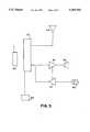
- FIG. 3is a block diagram of a docking system for a hand-held cellular telephone.
- FIG. 1there is shown a hand-held cellular or portable telephone docking arrangement 10, to permit a hand-held cellular or portable telephone 12 to be utilized within a vehicle or structure and as a personal telephone carried on an individual.
- the docking arrangement 10comprises a housing 16, fabricated typically from a metal, such as aluminum, or from a conductively coated plastic, such as a polycarbonate.
- the docking arrangementincludes the housing 16 which is divided into an antenna receiving compartment 18, and a cellular telephone receiving compartment 20.
- the antenna receiving compartment 18,is more fully resonant at the frequency range of about 860 MHz, and fully encloses an antenna 22 received therein, to provide RF shielding therefrom.
- the antenna compartment 18may have silver plated brass 24 lining the inner walls thereof, as shown in FIG. 1.
- the antenna compartment 18,preferably has interior dimensions of about 4.5 cm by about 1.9 cm by about 12.38 cm, or other dimensions which provides a rough equivalent volume in the antenna compartment 18, as the aforementioned dimensions.
- An antenna piercable wall structure for segregating the antenna compartment 18 from the usermay preferably be comprised of a ferrite attenuator 26, or partition, which acts as a choke between the antenna compartment 18 and the user and telephone compartment 20, to prevent the emmission from the antenna compartment 18, of stray RF energy, or at least lower it to an acceptable level.
- An opening 28is disposed within the ferrite attenuator 26, to permit an antenna 22 to be disposed within the compartment 18.
- a broadband coupling probe 30is arranged within the antenna compartment 18, and is connected, through appropriate coax cable to an external antenna (vehicle structure) as shown in FIG. 3, in block diagram form.
- the coupling probeis tuned to a central resonent frequency of about 860 MHz, with a nominal 50 ohm load at the terminal.
- the probe 30may also be comprised of an ungrounded capacitive coupling probe or plate, which serves the same function as the inductive probe.
- Other couplings 30may include radiation couplings and galvanic couplings which are arrangeable in close proximity to the antenna 22, for transmission to and from the external antenna.
- the telephone 12is arranged to be snugly received within the telephone compartment 20, as shown in FIGS. 1 and 2.
- the compartment 20,may have a capacitive ground backing plate 34, made of aluminum, in conductive communication with the housing 16.
- the housing 16is of course attached to an RF ground connector 36, such RF ground being carried to the ground side of the connector.
- the telephone compartment 20may have a biased charger pin arrangement 38, which is in connective communication with the electrical system of the structure (vehicle, building or airplane), to permit the hand-held cellular telephone 12 to be charged while it is emplaced within the docking arrangement 10.
- FIG. 3The block diagram of the docking arrangement 10, is shown in FIG. 3, wherein a hand held cellular telephone unit 50 is placed in antenna mating relationship with a coupling probe of a cellular phone dock 52.
- the dock 52is attached for example, to an external (automobile) antenna 54.
- the dock 52could be disposed in the wall of a building, or in an elevator, an airplane, or just about anywhere an external antenna may be arranged to pickup RF signals and keep them from close proximity to a person who is using the hand held cellular unit.
- the dockmay be actually built into a wall 68 of the entity using the dock 52, or it may be on an articulable arm 70, so as to bring the dock 52 within adjustable reach of people.
- the dock 52in any case, may be attached to an audio output amplifier 56 which feeds a signal to a loudspeaker 58, when it is set up in a vehicle.
- a remote mounted microphone 60is connected to a microphone null amplifier 57 and the output amplifier 56, to permit hands-free operation of a telephone 50 while using this docking arrangement 10 in an automobile (or other aforementioned facility) without acoustic feedback.
- the telephone unit 50is charged through a 12.8 volt regulator 59, which picks up power through the electrical system of the structure (automobile, building or airplane), to which the docking arrangement 10 is attached.
- the unitpermits efficient, inexpensive and convenient means for holding and operating a handheld cellular telephone within a vehicle, airplane or building, while effectively shielding the occupants from potentially harmful RF energy.
Landscapes
- Engineering & Computer Science (AREA)
- Computer Networks & Wireless Communication (AREA)
- Signal Processing (AREA)
- Telephone Set Structure (AREA)
- Fittings On The Vehicle Exterior For Carrying Loads, And Devices For Holding Or Mounting Articles (AREA)
Abstract
Description
Claims (16)
Priority Applications (14)
| Application Number | Priority Date | Filing Date | Title |
|---|---|---|---|
| US08/042,879US5493702A (en) | 1993-04-05 | 1993-04-05 | Antenna transmission coupling arrangement |
| PCT/US1995/014390WO1997017792A1 (en) | 1993-04-05 | 1995-11-07 | Antenna transmission coupling arrangement |
| US08/581,065US5711014A (en) | 1993-04-05 | 1995-12-29 | Antenna transmission coupling arrangement |
| US08/604,105US6594471B1 (en) | 1993-04-05 | 1996-02-20 | Radiative focal area antenna transmission coupling arrangement |
| US09/009,220US6112106A (en) | 1993-04-05 | 1998-01-20 | Antenna transmission coupling arrangement |
| US09/133,769US6064343A (en) | 1993-04-05 | 1998-08-12 | Antenna coupling arrangement |
| US09/634,140US6885845B1 (en) | 1993-04-05 | 2000-08-08 | Personal communication device connectivity arrangement |
| US10/619,770US7197285B2 (en) | 1993-04-05 | 2003-07-15 | Radiative focal area antenna transmission coupling arrangement |
| US11/020,450US7400858B2 (en) | 1993-04-05 | 2004-12-22 | Radiative focal area antenna transmission coupling arrangement |
| US11/115,020US7580733B2 (en) | 1993-04-05 | 2005-04-26 | Personal communication device connectivity arrangement |
| US11/728,487US7421253B2 (en) | 1993-04-05 | 2007-03-26 | Personal wireless communication device wireless connectivity arrangement |
| US12/218,324US7881664B2 (en) | 1993-04-05 | 2008-07-14 | Personal wireless communication device connectivity arrangement within an RF restricted environment |
| US12/378,452US7904124B2 (en) | 1993-04-05 | 2009-02-13 | Radiative focal area antenna transmission coupling arrangement |
| US12/931,050US8180279B2 (en) | 1993-04-05 | 2011-01-20 | Wireless hotspot arrangement |
Applications Claiming Priority (2)
| Application Number | Priority Date | Filing Date | Title |
|---|---|---|---|
| US08/042,879US5493702A (en) | 1993-04-05 | 1993-04-05 | Antenna transmission coupling arrangement |
| PCT/US1995/014390WO1997017792A1 (en) | 1993-04-05 | 1995-11-07 | Antenna transmission coupling arrangement |
Related Child Applications (3)
| Application Number | Title | Priority Date | Filing Date |
|---|---|---|---|
| US08851065Continuation-In-Part | 1995-12-29 | ||
| US08/581,065Continuation-In-PartUS5711014A (en) | 1993-04-05 | 1995-12-29 | Antenna transmission coupling arrangement |
| US09/009,220Continuation-In-PartUS6112106A (en) | 1993-04-05 | 1998-01-20 | Antenna transmission coupling arrangement |
Publications (1)
| Publication Number | Publication Date |
|---|---|
| US5493702Atrue US5493702A (en) | 1996-02-20 |
Family
ID=21924233
Family Applications (1)
| Application Number | Title | Priority Date | Filing Date |
|---|---|---|---|
| US08/042,879Expired - LifetimeUS5493702A (en) | 1993-04-05 | 1993-04-05 | Antenna transmission coupling arrangement |
Country Status (1)
| Country | Link |
|---|---|
| US (1) | US5493702A (en) |
Cited By (62)
| Publication number | Priority date | Publication date | Assignee | Title |
|---|---|---|---|---|
| WO1997037399A1 (en)* | 1996-04-02 | 1997-10-09 | Qualcomm Incorporated | Antenna coupler for a portable radiotelephone |
| US5711014A (en)* | 1993-04-05 | 1998-01-20 | Crowley; Robert J. | Antenna transmission coupling arrangement |
| WO1998025323A1 (en)* | 1996-12-04 | 1998-06-11 | Qualcomm Incorporated | Dual-band antenna coupler for a portable radiotelephone |
| US5777261A (en)* | 1993-02-04 | 1998-07-07 | Katz; Joseph M. | Assembly for attenuating emissions from portable telephones |
| US5809403A (en)* | 1996-03-11 | 1998-09-15 | Erisson Inc. | Coaxial cable assembly for a portable phone |
| US5874920A (en)* | 1996-01-26 | 1999-02-23 | Fujitsu Limited | Portable radio equipment, and built-in antenna mounting structure and shielding structure for the portable radio equipment |
| EP0955549A1 (en)* | 1998-05-05 | 1999-11-10 | Adeunis R.F. | Apparatus for radiofrequency measurements on an industrial test bench |
| US5999831A (en)* | 1996-04-01 | 1999-12-07 | Nec Corporation | Portable radio |
| US6088603A (en)* | 1995-10-27 | 2000-07-11 | Wilson; Leslie Ronald | Shielding device |
| US6108213A (en)* | 1998-06-22 | 2000-08-22 | Nec Corporation | Retainer for electronic apparatus |
| US6314273B1 (en)* | 1997-09-11 | 2001-11-06 | Mitsubishi Denki Kabushiki Kaisha | Mobile telecommunication apparatus having notches |
| US20020013159A1 (en)* | 2000-07-14 | 2002-01-31 | Matsushita Electric Industrial Co., Ltd. | Portable radio device having a structure for improving antenna characteristic |
| US20020044093A1 (en)* | 2000-04-05 | 2002-04-18 | Geyi Wen | Electrically connected multi-feed antenna system |
| US6413103B1 (en) | 2000-11-28 | 2002-07-02 | Apple Computer, Inc. | Method and apparatus for grounding microcoaxial cables inside a portable computing device |
| US6422900B1 (en) | 1999-09-15 | 2002-07-23 | Hh Tower Group | Coaxial cable coupling device |
| US20020140615A1 (en)* | 1999-09-20 | 2002-10-03 | Carles Puente Baliarda | Multilevel antennae |
| US20020171601A1 (en)* | 1999-10-26 | 2002-11-21 | Carles Puente Baliarda | Interlaced multiband antenna arrays |
| EP0895300A3 (en)* | 1997-07-29 | 2003-03-19 | Willtek Communications GmbH | Antenna coupler for testing of mobile telephones |
| US20030112190A1 (en)* | 2000-04-19 | 2003-06-19 | Baliarda Carles Puente | Advanced multilevel antenna for motor vehicles |
| US6594471B1 (en)* | 1993-04-05 | 2003-07-15 | Ambit Corp | Radiative focal area antenna transmission coupling arrangement |
| US6664930B2 (en) | 2001-04-12 | 2003-12-16 | Research In Motion Limited | Multiple-element antenna |
| US20040023610A1 (en)* | 2000-02-17 | 2004-02-05 | Applied Materials, Inc. | Conductive polishing article for electrochemical mechanical polishing |
| US20040038644A1 (en)* | 2002-08-22 | 2004-02-26 | Eagle Broadband, Inc. | Repeater for a satellite phone |
| US20040075613A1 (en)* | 2002-06-21 | 2004-04-22 | Perry Jarmuszewski | Multiple-element antenna with parasitic coupler |
| US20040119644A1 (en)* | 2000-10-26 | 2004-06-24 | Carles Puente-Baliarda | Antenna system for a motor vehicle |
| US20040145526A1 (en)* | 2001-04-16 | 2004-07-29 | Carles Puente Baliarda | Dual-band dual-polarized antenna array |
| US6791500B2 (en) | 2002-12-12 | 2004-09-14 | Research In Motion Limited | Antenna with near-field radiation control |
| US20040202312A1 (en)* | 2002-06-17 | 2004-10-14 | General Motors Corporation | Mobile vehicle housing for a portable communication device |
| US20040210482A1 (en)* | 2003-04-16 | 2004-10-21 | Tetsuhiko Keneaki | Gift certificate, gift certificate, issuing system, gift certificate using system |
| US6812897B2 (en) | 2002-12-17 | 2004-11-02 | Research In Motion Limited | Dual mode antenna system for radio transceiver |
| US20040227680A1 (en)* | 2003-05-14 | 2004-11-18 | Geyi Wen | Antenna with multiple-band patch and slot structures |
| EP1489682A1 (en)* | 2003-06-20 | 2004-12-22 | C.R.F. Società Consortile per Azioni | Vehicle equipped with an on-vehicle telecommunication system communicating with a user portable communication device housed in a shielding environment |
| US20040257285A1 (en)* | 2001-10-16 | 2004-12-23 | Quintero Lllera Ramiro | Multiband antenna |
| US20050001769A1 (en)* | 2003-06-12 | 2005-01-06 | Yihong Qi | Multiple-element antenna with floating antenna element |
| US20050017906A1 (en)* | 2003-07-24 | 2005-01-27 | Man Ying Tong | Floating conductor pad for antenna performance stabilization and noise reduction |
| US6870507B2 (en) | 2001-02-07 | 2005-03-22 | Fractus S.A. | Miniature broadband ring-like microstrip patch antenna |
| US6876320B2 (en) | 2001-11-30 | 2005-04-05 | Fractus, S.A. | Anti-radar space-filling and/or multilevel chaff dispersers |
| US6885845B1 (en)* | 1993-04-05 | 2005-04-26 | Ambit Corp. | Personal communication device connectivity arrangement |
| US20050190106A1 (en)* | 2001-10-16 | 2005-09-01 | Jaume Anguera Pros | Multifrequency microstrip patch antenna with parasitic coupled elements |
| US20050195112A1 (en)* | 2000-01-19 | 2005-09-08 | Baliarda Carles P. | Space-filling miniature antennas |
| US20060077101A1 (en)* | 2001-10-16 | 2006-04-13 | Carles Puente Baliarda | Loaded antenna |
| US20060290469A1 (en)* | 2001-11-21 | 2006-12-28 | Forster Ian J | Wireless communication device interconnectivity |
| US7204701B1 (en)* | 2004-03-08 | 2007-04-17 | Sun Microsystems, Inc. | Method and apparatus for reducing capacitively coupled radio frequency energy between a semiconductor device and an adjacent metal structure |
| US7245196B1 (en) | 2000-01-19 | 2007-07-17 | Fractus, S.A. | Fractal and space-filling transmission lines, resonators, filters and passive network elements |
| US20070257846A1 (en)* | 2004-05-13 | 2007-11-08 | Geyi Wen | Antenna with multiple-band patch and slot structures |
| US20080018543A1 (en)* | 2006-07-18 | 2008-01-24 | Carles Puente Baliarda | Multiple-body-configuration multimedia and smartphone multifunction wireless devices |
| US20090081947A1 (en)* | 2007-09-24 | 2009-03-26 | Paul Anthony Margis | System and Method for Receiving Broadcast Content on a Mobile Platform During Travel |
| US20090305746A1 (en)* | 2006-04-12 | 2009-12-10 | Funkwerk Dabendorf Gmbh | Device for Coupling and Housing a Mobile Telephone in a Motor Vehicle |
| US20100152962A1 (en)* | 2008-12-15 | 2010-06-17 | Panasonic Avionics Corporation | System and Method for Performing Real-Time Data Analysis |
| US20100318794A1 (en)* | 2009-06-11 | 2010-12-16 | Panasonic Avionics Corporation | System and Method for Providing Security Aboard a Moving Platform |
| US7937127B1 (en)* | 1999-03-18 | 2011-05-03 | Panasonic Corporation | Radio terminal device |
| US20110184579A1 (en)* | 2009-12-14 | 2011-07-28 | Panasonic Avionics Corporation | System and Method for Providing Dynamic Power Management |
| US20120062441A1 (en)* | 2010-02-13 | 2012-03-15 | Peiker Acustic Gmbh & Co. Kg | Arrangement for coupling a mobile phone to an external antenna |
| US8704960B2 (en) | 2010-04-27 | 2014-04-22 | Panasonic Avionics Corporation | Deployment system and method for user interface devices |
| US20150043424A1 (en)* | 2013-08-06 | 2015-02-12 | The Boeing Company | Wired ethernet adaptor for portable electronic devices |
| US20150070236A1 (en)* | 2013-09-09 | 2015-03-12 | Apple Inc. | Electronic Device With Electromagnetic Shielding Structures |
| US9016627B2 (en) | 2009-10-02 | 2015-04-28 | Panasonic Avionics Corporation | System and method for providing an integrated user interface system at a seat |
| US9108733B2 (en) | 2010-09-10 | 2015-08-18 | Panasonic Avionics Corporation | Integrated user interface system and method |
| US9307297B2 (en) | 2013-03-15 | 2016-04-05 | Panasonic Avionics Corporation | System and method for providing multi-mode wireless data distribution |
| US20160134017A1 (en)* | 2014-11-06 | 2016-05-12 | Chiun Mai Communication Systems, Inc. | Multiband antenna and wireless communication device |
| US9755314B2 (en) | 2001-10-16 | 2017-09-05 | Fractus S.A. | Loaded antenna |
| US11518540B2 (en)* | 2018-06-15 | 2022-12-06 | Airbus Operations Gmbh | Aircraft having an aircraft fuselage, a wing assembly, and a tail assembly, as well as a surface structure containing a lightning protection device |
Citations (3)
| Publication number | Priority date | Publication date | Assignee | Title |
|---|---|---|---|---|
| US4740794A (en)* | 1986-01-03 | 1988-04-26 | Motorola, Inc. | Connectorless antenna coupler |
| US4850006A (en)* | 1986-11-18 | 1989-07-18 | Nec Corporation | Booster and charger unit used for hand-held portable telephone and having overheat protection circuit |
| US5335366A (en)* | 1993-02-01 | 1994-08-02 | Daniels John J | Radiation shielding apparatus for a radio transmitting device |
- 1993
- 1993-04-05USUS08/042,879patent/US5493702A/ennot_activeExpired - Lifetime
Patent Citations (3)
| Publication number | Priority date | Publication date | Assignee | Title |
|---|---|---|---|---|
| US4740794A (en)* | 1986-01-03 | 1988-04-26 | Motorola, Inc. | Connectorless antenna coupler |
| US4850006A (en)* | 1986-11-18 | 1989-07-18 | Nec Corporation | Booster and charger unit used for hand-held portable telephone and having overheat protection circuit |
| US5335366A (en)* | 1993-02-01 | 1994-08-02 | Daniels John J | Radiation shielding apparatus for a radio transmitting device |
Cited By (193)
| Publication number | Priority date | Publication date | Assignee | Title |
|---|---|---|---|---|
| US5777261A (en)* | 1993-02-04 | 1998-07-07 | Katz; Joseph M. | Assembly for attenuating emissions from portable telephones |
| US5711014A (en)* | 1993-04-05 | 1998-01-20 | Crowley; Robert J. | Antenna transmission coupling arrangement |
| US7400858B2 (en)* | 1993-04-05 | 2008-07-15 | Ambit Corp | Radiative focal area antenna transmission coupling arrangement |
| US6594471B1 (en)* | 1993-04-05 | 2003-07-15 | Ambit Corp | Radiative focal area antenna transmission coupling arrangement |
| US20100178880A1 (en)* | 1993-04-05 | 2010-07-15 | Crowley Robert J | Radiative focal area antenna transmission coupling arrangement |
| US6885845B1 (en)* | 1993-04-05 | 2005-04-26 | Ambit Corp. | Personal communication device connectivity arrangement |
| US7580733B2 (en) | 1993-04-05 | 2009-08-25 | Ambit Corp | Personal communication device connectivity arrangement |
| US7881664B2 (en) | 1993-04-05 | 2011-02-01 | Ambit Corp | Personal wireless communication device connectivity arrangement within an RF restricted environment |
| US7904124B2 (en) | 1993-04-05 | 2011-03-08 | Ambit Corp | Radiative focal area antenna transmission coupling arrangement |
| US20050200536A1 (en)* | 1993-04-05 | 2005-09-15 | Crowley Robert J. | Personal communication device connectivity arrangement |
| US6112106A (en)* | 1993-04-05 | 2000-08-29 | Crowley; Robert J. | Antenna transmission coupling arrangement |
| US6088603A (en)* | 1995-10-27 | 2000-07-11 | Wilson; Leslie Ronald | Shielding device |
| US5874920A (en)* | 1996-01-26 | 1999-02-23 | Fujitsu Limited | Portable radio equipment, and built-in antenna mounting structure and shielding structure for the portable radio equipment |
| US5809403A (en)* | 1996-03-11 | 1998-09-15 | Erisson Inc. | Coaxial cable assembly for a portable phone |
| US5999831A (en)* | 1996-04-01 | 1999-12-07 | Nec Corporation | Portable radio |
| AU713865B2 (en)* | 1996-04-02 | 1999-12-09 | Qualcomm Incorporated | Antenna coupler for a portable radiotelephone |
| US5812094A (en)* | 1996-04-02 | 1998-09-22 | Qualcomm Incorporated | Antenna coupler for a portable radiotelephone |
| RU2204185C2 (en)* | 1996-04-02 | 2003-05-10 | Квэлкомм Инкорпорейтед | Communication device with portable radiophone antenna |
| US5852421A (en)* | 1996-04-02 | 1998-12-22 | Qualcomm Incorporated | Dual-band antenna coupler for a portable radiotelephone |
| WO1997037399A1 (en)* | 1996-04-02 | 1997-10-09 | Qualcomm Incorporated | Antenna coupler for a portable radiotelephone |
| AU724641B2 (en)* | 1996-12-04 | 2000-09-28 | Qualcomm Incorporated | Dual-band antenna coupler for a portable radiotelephone |
| RU2208298C2 (en)* | 1996-12-04 | 2003-07-10 | Квэлкомм Инкорпорейтед | Dual-band antenna coupling device for portable radiophone |
| WO1998025323A1 (en)* | 1996-12-04 | 1998-06-11 | Qualcomm Incorporated | Dual-band antenna coupler for a portable radiotelephone |
| EP0895300A3 (en)* | 1997-07-29 | 2003-03-19 | Willtek Communications GmbH | Antenna coupler for testing of mobile telephones |
| US6314273B1 (en)* | 1997-09-11 | 2001-11-06 | Mitsubishi Denki Kabushiki Kaisha | Mobile telecommunication apparatus having notches |
| EP0955549A1 (en)* | 1998-05-05 | 1999-11-10 | Adeunis R.F. | Apparatus for radiofrequency measurements on an industrial test bench |
| FR2778465A1 (en)* | 1998-05-05 | 1999-11-12 | Adeunis R F | RADIO FREQUENCY MEASURING DEVICE FOR AN INDUSTRIAL TEST BENCH |
| US6108213A (en)* | 1998-06-22 | 2000-08-22 | Nec Corporation | Retainer for electronic apparatus |
| US7937127B1 (en)* | 1999-03-18 | 2011-05-03 | Panasonic Corporation | Radio terminal device |
| US6422900B1 (en) | 1999-09-15 | 2002-07-23 | Hh Tower Group | Coaxial cable coupling device |
| US8009111B2 (en) | 1999-09-20 | 2011-08-30 | Fractus, S.A. | Multilevel antennae |
| US9240632B2 (en) | 1999-09-20 | 2016-01-19 | Fractus, S.A. | Multilevel antennae |
| US9054421B2 (en) | 1999-09-20 | 2015-06-09 | Fractus, S.A. | Multilevel antennae |
| US20090167625A1 (en)* | 1999-09-20 | 2009-07-02 | Fractus, S.A. | Multilevel antennae |
| US8154462B2 (en) | 1999-09-20 | 2012-04-10 | Fractus, S.A. | Multilevel antennae |
| US7528782B2 (en) | 1999-09-20 | 2009-05-05 | Fractus, S.A. | Multilevel antennae |
| US8154463B2 (en) | 1999-09-20 | 2012-04-10 | Fractus, S.A. | Multilevel antennae |
| US7505007B2 (en) | 1999-09-20 | 2009-03-17 | Fractus, S.A. | Multi-level antennae |
| US20050259009A1 (en)* | 1999-09-20 | 2005-11-24 | Carles Puente Baliarda | Multilevel antennae |
| US10056682B2 (en) | 1999-09-20 | 2018-08-21 | Fractus, S.A. | Multilevel antennae |
| US7015868B2 (en) | 1999-09-20 | 2006-03-21 | Fractus, S.A. | Multilevel Antennae |
| US9000985B2 (en) | 1999-09-20 | 2015-04-07 | Fractus, S.A. | Multilevel antennae |
| US9761934B2 (en) | 1999-09-20 | 2017-09-12 | Fractus, S.A. | Multilevel antennae |
| US7397431B2 (en) | 1999-09-20 | 2008-07-08 | Fractus, S.A. | Multilevel antennae |
| US7394432B2 (en) | 1999-09-20 | 2008-07-01 | Fractus, S.A. | Multilevel antenna |
| US9362617B2 (en) | 1999-09-20 | 2016-06-07 | Fractus, S.A. | Multilevel antennae |
| US8330659B2 (en) | 1999-09-20 | 2012-12-11 | Fractus, S.A. | Multilevel antennae |
| US7123208B2 (en) | 1999-09-20 | 2006-10-17 | Fractus, S.A. | Multilevel antennae |
| US8976069B2 (en) | 1999-09-20 | 2015-03-10 | Fractus, S.A. | Multilevel antennae |
| US20060290573A1 (en)* | 1999-09-20 | 2006-12-28 | Carles Puente Baliarda | Multilevel antennae |
| US20050110688A1 (en)* | 1999-09-20 | 2005-05-26 | Baliarda Carles P. | Multilevel antennae |
| US20020140615A1 (en)* | 1999-09-20 | 2002-10-03 | Carles Puente Baliarda | Multilevel antennae |
| US8941541B2 (en) | 1999-09-20 | 2015-01-27 | Fractus, S.A. | Multilevel antennae |
| US7250918B2 (en) | 1999-10-26 | 2007-07-31 | Fractus, S.A. | Interlaced multiband antenna arrays |
| US20050146481A1 (en)* | 1999-10-26 | 2005-07-07 | Baliarda Carles P. | Interlaced multiband antenna arrays |
| US8896493B2 (en) | 1999-10-26 | 2014-11-25 | Fractus, S.A. | Interlaced multiband antenna arrays |
| US6937191B2 (en) | 1999-10-26 | 2005-08-30 | Fractus, S.A. | Interlaced multiband antenna arrays |
| US20020171601A1 (en)* | 1999-10-26 | 2002-11-21 | Carles Puente Baliarda | Interlaced multiband antenna arrays |
| US20090267863A1 (en)* | 1999-10-26 | 2009-10-29 | Carles Puente Baliarda | Interlaced multiband antenna arrays |
| US7932870B2 (en) | 1999-10-26 | 2011-04-26 | Fractus, S.A. | Interlaced multiband antenna arrays |
| US9905940B2 (en) | 1999-10-26 | 2018-02-27 | Fractus, S.A. | Interlaced multiband antenna arrays |
| US8228256B2 (en) | 1999-10-26 | 2012-07-24 | Fractus, S.A. | Interlaced multiband antenna arrays |
| US7557768B2 (en) | 1999-10-26 | 2009-07-07 | Fractus, S.A. | Interlaced multiband antenna arrays |
| US20050231427A1 (en)* | 2000-01-19 | 2005-10-20 | Carles Puente Baliarda | Space-filling miniature antennas |
| US7202822B2 (en) | 2000-01-19 | 2007-04-10 | Fractus, S.A. | Space-filling miniature antennas |
| US20110177839A1 (en)* | 2000-01-19 | 2011-07-21 | Fractus, S.A. | Space-filling miniature antennas |
| US8207893B2 (en) | 2000-01-19 | 2012-06-26 | Fractus, S.A. | Space-filling miniature antennas |
| US10355346B2 (en) | 2000-01-19 | 2019-07-16 | Fractus, S.A. | Space-filling miniature antennas |
| US9331382B2 (en) | 2000-01-19 | 2016-05-03 | Fractus, S.A. | Space-filling miniature antennas |
| US8471772B2 (en) | 2000-01-19 | 2013-06-25 | Fractus, S.A. | Space-filling miniature antennas |
| US20080011509A1 (en)* | 2000-01-19 | 2008-01-17 | Baliarda Carles P | Fractal and space-filling transmission lines, resonators, filters and passive network elements |
| US20050195112A1 (en)* | 2000-01-19 | 2005-09-08 | Baliarda Carles P. | Space-filling miniature antennas |
| US20110181478A1 (en)* | 2000-01-19 | 2011-07-28 | Fractus, S.A. | Space-filling miniature antennas |
| US7148850B2 (en) | 2000-01-19 | 2006-12-12 | Fractus, S.A. | Space-filling miniature antennas |
| US8558741B2 (en) | 2000-01-19 | 2013-10-15 | Fractus, S.A. | Space-filling miniature antennas |
| US8610627B2 (en) | 2000-01-19 | 2013-12-17 | Fractus, S.A. | Space-filling miniature antennas |
| US20110181481A1 (en)* | 2000-01-19 | 2011-07-28 | Fractus, S.A. | Space-filling miniature antennas |
| US7164386B2 (en) | 2000-01-19 | 2007-01-16 | Fractus, S.A. | Space-filling miniature antennas |
| US7538641B2 (en) | 2000-01-19 | 2009-05-26 | Fractus, S.A. | Fractal and space-filling transmission lines, resonators, filters and passive network elements |
| US20050264453A1 (en)* | 2000-01-19 | 2005-12-01 | Baliarda Carles P | Space-filling miniature antennas |
| US8212726B2 (en) | 2000-01-19 | 2012-07-03 | Fractus, Sa | Space-filling miniature antennas |
| US7245196B1 (en) | 2000-01-19 | 2007-07-17 | Fractus, S.A. | Fractal and space-filling transmission lines, resonators, filters and passive network elements |
| US7554490B2 (en) | 2000-01-19 | 2009-06-30 | Fractus, S.A. | Space-filling miniature antennas |
| US20040023610A1 (en)* | 2000-02-17 | 2004-02-05 | Applied Materials, Inc. | Conductive polishing article for electrochemical mechanical polishing |
| US20020044093A1 (en)* | 2000-04-05 | 2002-04-18 | Geyi Wen | Electrically connected multi-feed antenna system |
| US6781548B2 (en) | 2000-04-05 | 2004-08-24 | Research In Motion Limited | Electrically connected multi-feed antenna system |
| US6809692B2 (en) | 2000-04-19 | 2004-10-26 | Advanced Automotive Antennas, S.L. | Advanced multilevel antenna for motor vehicles |
| US20030112190A1 (en)* | 2000-04-19 | 2003-06-19 | Baliarda Carles Puente | Advanced multilevel antenna for motor vehicles |
| US20020013159A1 (en)* | 2000-07-14 | 2002-01-31 | Matsushita Electric Industrial Co., Ltd. | Portable radio device having a structure for improving antenna characteristic |
| GB2366082A (en)* | 2000-07-14 | 2002-02-27 | Matsushita Electric Industrial Co Ltd | Portable radio device with metal cover |
| US20040119644A1 (en)* | 2000-10-26 | 2004-06-24 | Carles Puente-Baliarda | Antenna system for a motor vehicle |
| US7511675B2 (en) | 2000-10-26 | 2009-03-31 | Advanced Automotive Antennas, S.L. | Antenna system for a motor vehicle |
| US6413103B1 (en) | 2000-11-28 | 2002-07-02 | Apple Computer, Inc. | Method and apparatus for grounding microcoaxial cables inside a portable computing device |
| US6870507B2 (en) | 2001-02-07 | 2005-03-22 | Fractus S.A. | Miniature broadband ring-like microstrip patch antenna |
| US6664930B2 (en) | 2001-04-12 | 2003-12-16 | Research In Motion Limited | Multiple-element antenna |
| US6950071B2 (en) | 2001-04-12 | 2005-09-27 | Research In Motion Limited | Multiple-element antenna |
| US20040004574A1 (en)* | 2001-04-12 | 2004-01-08 | Geyi Wen | Multiple-element antenna |
| US20040145526A1 (en)* | 2001-04-16 | 2004-07-29 | Carles Puente Baliarda | Dual-band dual-polarized antenna array |
| US6937206B2 (en) | 2001-04-16 | 2005-08-30 | Fractus, S.A. | Dual-band dual-polarized antenna array |
| US7202818B2 (en) | 2001-10-16 | 2007-04-10 | Fractus, S.A. | Multifrequency microstrip patch antenna with parasitic coupled elements |
| US20060077101A1 (en)* | 2001-10-16 | 2006-04-13 | Carles Puente Baliarda | Loaded antenna |
| US8228245B2 (en) | 2001-10-16 | 2012-07-24 | Fractus, S.A. | Multiband antenna |
| US7920097B2 (en) | 2001-10-16 | 2011-04-05 | Fractus, S.A. | Multiband antenna |
| US9755314B2 (en) | 2001-10-16 | 2017-09-05 | Fractus S.A. | Loaded antenna |
| US20040257285A1 (en)* | 2001-10-16 | 2004-12-23 | Quintero Lllera Ramiro | Multiband antenna |
| US7312762B2 (en) | 2001-10-16 | 2007-12-25 | Fractus, S.A. | Loaded antenna |
| US7215287B2 (en) | 2001-10-16 | 2007-05-08 | Fractus S.A. | Multiband antenna |
| US8723742B2 (en) | 2001-10-16 | 2014-05-13 | Fractus, S.A. | Multiband antenna |
| US7541997B2 (en) | 2001-10-16 | 2009-06-02 | Fractus, S.A. | Loaded antenna |
| US20050190106A1 (en)* | 2001-10-16 | 2005-09-01 | Jaume Anguera Pros | Multifrequency microstrip patch antenna with parasitic coupled elements |
| US20070132658A1 (en)* | 2001-10-16 | 2007-06-14 | Ramiro Quintero Illera | Multiband antenna |
| US7439923B2 (en) | 2001-10-16 | 2008-10-21 | Fractus, S.A. | Multiband antenna |
| US20090237316A1 (en)* | 2001-10-16 | 2009-09-24 | Carles Puente Baliarda | Loaded antenna |
| US20070001843A1 (en)* | 2001-11-21 | 2007-01-04 | Marconi Communications, Inc. | Wireless communication device interconnectivity |
| US7623831B2 (en) | 2001-11-21 | 2009-11-24 | Ian J Forster | Wireless communication device interconnectivity |
| US20060290469A1 (en)* | 2001-11-21 | 2006-12-28 | Forster Ian J | Wireless communication device interconnectivity |
| US7536155B2 (en)* | 2001-11-21 | 2009-05-19 | Ian J Forster | Wireless communication device interconnectivity |
| US6876320B2 (en) | 2001-11-30 | 2005-04-05 | Fractus, S.A. | Anti-radar space-filling and/or multilevel chaff dispersers |
| US7110537B2 (en)* | 2002-06-17 | 2006-09-19 | General Motors Corporation | Mobile vehicle housing for a portable communication device |
| US20040202312A1 (en)* | 2002-06-17 | 2004-10-14 | General Motors Corporation | Mobile vehicle housing for a portable communication device |
| US6891506B2 (en) | 2002-06-21 | 2005-05-10 | Research In Motion Limited | Multiple-element antenna with parasitic coupler |
| US7183984B2 (en) | 2002-06-21 | 2007-02-27 | Research In Motion Limited | Multiple-element antenna with parasitic coupler |
| US20040075613A1 (en)* | 2002-06-21 | 2004-04-22 | Perry Jarmuszewski | Multiple-element antenna with parasitic coupler |
| US20050200537A1 (en)* | 2002-06-21 | 2005-09-15 | Research In Motion Limited | Multiple-element antenna with parasitic coupler |
| US20040038644A1 (en)* | 2002-08-22 | 2004-02-26 | Eagle Broadband, Inc. | Repeater for a satellite phone |
| US6996369B2 (en) | 2002-08-22 | 2006-02-07 | Eagle Broadband, Inc. | Repeater for a satellite phone |
| US20050040996A1 (en)* | 2002-12-12 | 2005-02-24 | Yihong Qi | Antenna with near-field radiation control |
| US8525743B2 (en) | 2002-12-12 | 2013-09-03 | Blackberry Limited | Antenna with near-field radiation control |
| US6791500B2 (en) | 2002-12-12 | 2004-09-14 | Research In Motion Limited | Antenna with near-field radiation control |
| US8339323B2 (en) | 2002-12-12 | 2012-12-25 | Research In Motion Limited | Antenna with near-field radiation control |
| US8223078B2 (en) | 2002-12-12 | 2012-07-17 | Research In Motion Limited | Antenna with near-field radiation control |
| US20090009419A1 (en)* | 2002-12-12 | 2009-01-08 | Yihong Qi | Antenna with near-field radiation control |
| US7253775B2 (en) | 2002-12-12 | 2007-08-07 | Research In Motion Limited | Antenna with near-field radiation control |
| US8125397B2 (en) | 2002-12-12 | 2012-02-28 | Research In Motion Limited | Antenna with near-field radiation control |
| US7961154B2 (en) | 2002-12-12 | 2011-06-14 | Research In Motion Limited | Antenna with near-field radiation control |
| US7541991B2 (en) | 2002-12-12 | 2009-06-02 | Research In Motion Limited | Antenna with near-field radiation control |
| US6812897B2 (en) | 2002-12-17 | 2004-11-02 | Research In Motion Limited | Dual mode antenna system for radio transceiver |
| US20040210482A1 (en)* | 2003-04-16 | 2004-10-21 | Tetsuhiko Keneaki | Gift certificate, gift certificate, issuing system, gift certificate using system |
| US7256741B2 (en) | 2003-05-14 | 2007-08-14 | Research In Motion Limited | Antenna with multiple-band patch and slot structures |
| US20040227680A1 (en)* | 2003-05-14 | 2004-11-18 | Geyi Wen | Antenna with multiple-band patch and slot structures |
| US7023387B2 (en) | 2003-05-14 | 2006-04-04 | Research In Motion Limited | Antenna with multiple-band patch and slot structures |
| US7400300B2 (en) | 2003-06-12 | 2008-07-15 | Research In Motion Limited | Multiple-element antenna with floating antenna element |
| US20080246668A1 (en)* | 2003-06-12 | 2008-10-09 | Yihong Qi | Multiple-element antenna with floating antenna element |
| US8018386B2 (en) | 2003-06-12 | 2011-09-13 | Research In Motion Limited | Multiple-element antenna with floating antenna element |
| US20050001769A1 (en)* | 2003-06-12 | 2005-01-06 | Yihong Qi | Multiple-element antenna with floating antenna element |
| US20070176835A1 (en)* | 2003-06-12 | 2007-08-02 | Yihong Qi | Multiple-element antenna with floating antenna element |
| US7148846B2 (en) | 2003-06-12 | 2006-12-12 | Research In Motion Limited | Multiple-element antenna with floating antenna element |
| US7409235B2 (en) | 2003-06-20 | 2008-08-05 | C.R.F. Societa Consortile Per Azioni | Vehicle equipped with an on-vehicle telecommunication system communicating with a user portable communication device housed in a shielding environment |
| US20050037825A1 (en)* | 2003-06-20 | 2005-02-17 | C.R.F. Societa Consortile Per Azioni | Vehicle equipped with an on-vehicle telecommunication system communicating with a user portable communication device housed in a shielding environment |
| EP1489682A1 (en)* | 2003-06-20 | 2004-12-22 | C.R.F. Società Consortile per Azioni | Vehicle equipped with an on-vehicle telecommunication system communicating with a user portable communication device housed in a shielding environment |
| US6980173B2 (en) | 2003-07-24 | 2005-12-27 | Research In Motion Limited | Floating conductor pad for antenna performance stabilization and noise reduction |
| US20050017906A1 (en)* | 2003-07-24 | 2005-01-27 | Man Ying Tong | Floating conductor pad for antenna performance stabilization and noise reduction |
| US7204701B1 (en)* | 2004-03-08 | 2007-04-17 | Sun Microsystems, Inc. | Method and apparatus for reducing capacitively coupled radio frequency energy between a semiconductor device and an adjacent metal structure |
| US7369089B2 (en) | 2004-05-13 | 2008-05-06 | Research In Motion Limited | Antenna with multiple-band patch and slot structures |
| US20070257846A1 (en)* | 2004-05-13 | 2007-11-08 | Geyi Wen | Antenna with multiple-band patch and slot structures |
| US8238984B2 (en) | 2006-04-12 | 2012-08-07 | Funkwerk Dabendorf Gmbh | Device for coupling and housing a mobile telephone in a motor vehicle |
| US20090305746A1 (en)* | 2006-04-12 | 2009-12-10 | Funkwerk Dabendorf Gmbh | Device for Coupling and Housing a Mobile Telephone in a Motor Vehicle |
| US10644380B2 (en) | 2006-07-18 | 2020-05-05 | Fractus, S.A. | Multiple-body-configuration multimedia and smartphone multifunction wireless devices |
| US12095149B2 (en) | 2006-07-18 | 2024-09-17 | Fractus, S.A. | Multiple-body-configuration multimedia and smartphone multifunction wireless devices |
| US11349200B2 (en) | 2006-07-18 | 2022-05-31 | Fractus, S.A. | Multiple-body-configuration multimedia and smartphone multifunction wireless devices |
| US9899727B2 (en) | 2006-07-18 | 2018-02-20 | Fractus, S.A. | Multiple-body-configuration multimedia and smartphone multifunction wireless devices |
| US11031677B2 (en) | 2006-07-18 | 2021-06-08 | Fractus, S.A. | Multiple-body-configuration multimedia and smartphone multifunction wireless devices |
| US8738103B2 (en) | 2006-07-18 | 2014-05-27 | Fractus, S.A. | Multiple-body-configuration multimedia and smartphone multifunction wireless devices |
| US11735810B2 (en) | 2006-07-18 | 2023-08-22 | Fractus, S.A. | Multiple-body-configuration multimedia and smartphone multifunction wireless devices |
| US20080018543A1 (en)* | 2006-07-18 | 2008-01-24 | Carles Puente Baliarda | Multiple-body-configuration multimedia and smartphone multifunction wireless devices |
| US9099773B2 (en) | 2006-07-18 | 2015-08-04 | Fractus, S.A. | Multiple-body-configuration multimedia and smartphone multifunction wireless devices |
| US20090081947A1 (en)* | 2007-09-24 | 2009-03-26 | Paul Anthony Margis | System and Method for Receiving Broadcast Content on a Mobile Platform During Travel |
| US9185433B2 (en) | 2007-09-24 | 2015-11-10 | Panasonic Avionics Corporation | System and method for receiving broadcast content on a mobile platform during travel |
| US8326282B2 (en) | 2007-09-24 | 2012-12-04 | Panasonic Avionics Corporation | System and method for receiving broadcast content on a mobile platform during travel |
| US9872154B2 (en) | 2007-09-24 | 2018-01-16 | Panasonic Avionics Corporation | System and method for receiving broadcast content on a mobile platform during travel |
| US20100152962A1 (en)* | 2008-12-15 | 2010-06-17 | Panasonic Avionics Corporation | System and Method for Performing Real-Time Data Analysis |
| US8509990B2 (en) | 2008-12-15 | 2013-08-13 | Panasonic Avionics Corporation | System and method for performing real-time data analysis |
| US20100318794A1 (en)* | 2009-06-11 | 2010-12-16 | Panasonic Avionics Corporation | System and Method for Providing Security Aboard a Moving Platform |
| US8402268B2 (en) | 2009-06-11 | 2013-03-19 | Panasonic Avionics Corporation | System and method for providing security aboard a moving platform |
| US9016627B2 (en) | 2009-10-02 | 2015-04-28 | Panasonic Avionics Corporation | System and method for providing an integrated user interface system at a seat |
| US10556684B2 (en) | 2009-10-02 | 2020-02-11 | Panasonic Avionics Corporation | System and method for providing an integrated user interface system at a seat |
| USD904328S1 (en) | 2009-10-02 | 2020-12-08 | Panasonic Avionics Corporation | Display |
| US10011357B2 (en) | 2009-10-02 | 2018-07-03 | Panasonic Avionics Corporation | System and method for providing an integrated user interface system at a seat |
| US20110184579A1 (en)* | 2009-12-14 | 2011-07-28 | Panasonic Avionics Corporation | System and Method for Providing Dynamic Power Management |
| US8897924B2 (en) | 2009-12-14 | 2014-11-25 | Panasonic Avionics Corporation | System and method for providing dynamic power management |
| US8504217B2 (en) | 2009-12-14 | 2013-08-06 | Panasonic Avionics Corporation | System and method for providing dynamic power management |
| US20120062441A1 (en)* | 2010-02-13 | 2012-03-15 | Peiker Acustic Gmbh & Co. Kg | Arrangement for coupling a mobile phone to an external antenna |
| US9136895B2 (en)* | 2010-02-13 | 2015-09-15 | Peiker Acustic Gmbh & Co. Kg | Arrangement for coupling a mobile phone to an external antenna |
| US8704960B2 (en) | 2010-04-27 | 2014-04-22 | Panasonic Avionics Corporation | Deployment system and method for user interface devices |
| US9108733B2 (en) | 2010-09-10 | 2015-08-18 | Panasonic Avionics Corporation | Integrated user interface system and method |
| US9307297B2 (en) | 2013-03-15 | 2016-04-05 | Panasonic Avionics Corporation | System and method for providing multi-mode wireless data distribution |
| US20150043424A1 (en)* | 2013-08-06 | 2015-02-12 | The Boeing Company | Wired ethernet adaptor for portable electronic devices |
| US9698467B2 (en)* | 2013-08-06 | 2017-07-04 | The Boeing Company | Wired ethernet adaptor for portable electronic devices |
| US9520645B2 (en)* | 2013-09-09 | 2016-12-13 | Apple Inc. | Electronic device with electromagnetic shielding structures |
| US20150070236A1 (en)* | 2013-09-09 | 2015-03-12 | Apple Inc. | Electronic Device With Electromagnetic Shielding Structures |
| US20160134017A1 (en)* | 2014-11-06 | 2016-05-12 | Chiun Mai Communication Systems, Inc. | Multiband antenna and wireless communication device |
| US9627755B2 (en)* | 2014-11-06 | 2017-04-18 | Chiun Mai Communication Systems, Inc. | Multiband antenna and wireless communication device |
| US11518540B2 (en)* | 2018-06-15 | 2022-12-06 | Airbus Operations Gmbh | Aircraft having an aircraft fuselage, a wing assembly, and a tail assembly, as well as a surface structure containing a lightning protection device |
Similar Documents
| Publication | Publication Date | Title |
|---|---|---|
| US5493702A (en) | Antenna transmission coupling arrangement | |
| US5711014A (en) | Antenna transmission coupling arrangement | |
| US8238984B2 (en) | Device for coupling and housing a mobile telephone in a motor vehicle | |
| US6031492A (en) | Mobile cradle antenna and heat sink enhancement | |
| US4661992A (en) | Switchless external antenna connector for portable radios | |
| US8112131B2 (en) | Radiative focal area antenna transmission coupling arrangement | |
| US6594471B1 (en) | Radiative focal area antenna transmission coupling arrangement | |
| US5812094A (en) | Antenna coupler for a portable radiotelephone | |
| CN102629782B (en) | Contactless power transmission device | |
| EP0663749B1 (en) | Hands free equipment for a mobile telephone | |
| MXPA97009334A (en) | Antenna coupler for a portable radiotelephone | |
| US6885845B1 (en) | Personal communication device connectivity arrangement | |
| JPH08265024A (en) | Antenna assembly, active repeater assembly and signal transmission method | |
| EP0941556A1 (en) | Dual-band antenna coupler for a portable radiotelephone | |
| US5739790A (en) | RF docking adapter for portable transceivers, communication system and method for use with the same | |
| KR102023499B1 (en) | Resonator circuit for resonance wireless power receiving apparatus | |
| WO1997017792A1 (en) | Antenna transmission coupling arrangement | |
| JP2001345620A (en) | Mobile telephone antenna device | |
| JP2004356895A (en) | External antenna connection structure for wireless communication terminals | |
| US20040204188A1 (en) | Grounding system for a cell phone | |
| JP2000013293A (en) | Satellite radio broadcast receiving antenna unit for onboard vehicles | |
| JP2001339496A (en) | Portable radio device | |
| HK1010943B (en) | Antenna coupler for a portable radiotelephone | |
| JPH11164007A (en) | Hands-free telephone equipment and telephone system using the same |
Legal Events
| Date | Code | Title | Description |
|---|---|---|---|
| STPP | Information on status: patent application and granting procedure in general | Free format text:APPLICATION UNDERGOING PREEXAM PROCESSING | |
| AS | Assignment | Owner name:AMBIT CORP, MASSACHUSETTS Free format text:ASSIGNMENT OF ASSIGNORS INTEREST;ASSIGNORS:CROWLEY, ROBERT J.;HALGREN, DONALD N.;REEL/FRAME:009414/0155 Effective date:19980826 | |
| REMI | Maintenance fee reminder mailed | ||
| FPAY | Fee payment | Year of fee payment:4 | |
| SULP | Surcharge for late payment | ||
| REMI | Maintenance fee reminder mailed | ||
| FPAY | Fee payment | Year of fee payment:8 | |
| SULP | Surcharge for late payment | Year of fee payment:7 | |
| REMI | Maintenance fee reminder mailed | ||
| FPAY | Fee payment | Year of fee payment:12 | |
| SULP | Surcharge for late payment | Year of fee payment:11 | |
| FEPP | Fee payment procedure | Free format text:PAT HOLDER NO LONGER CLAIMS SMALL ENTITY STATUS, ENTITY STATUS SET TO UNDISCOUNTED (ORIGINAL EVENT CODE: STOL); ENTITY STATUS OF PATENT OWNER: LARGE ENTITY | |
| SULP | Surcharge for late payment | ||
| AS | Assignment | Owner name:CHESTER HOLDINGS, LLC, MASSACHUSETTS Free format text:ASSIGNMENT OF ASSIGNORS INTEREST;ASSIGNORS:CROWLEY, ROBERT J.;HALGREN, DONALD N., DBA AMBIT CORP;REEL/FRAME:026742/0311 Effective date:20110728 | |
| AS | Assignment | Owner name:ANTENNATECH LLC, TEXAS Free format text:ASSIGNMENT OF ASSIGNORS INTEREST;ASSIGNOR:CHESTER HOLDINGS, LLC;REEL/FRAME:032661/0616 Effective date:20140331 |