US5492458A - Stator of electric fan - Google Patents
Stator of electric fanDownload PDFInfo
- Publication number
- US5492458A US5492458AUS08/369,298US36929895AUS5492458AUS 5492458 AUS5492458 AUS 5492458AUS 36929895 AUS36929895 AUS 36929895AUS 5492458 AUS5492458 AUS 5492458A
- Authority
- US
- United States
- Prior art keywords
- shaft
- center hole
- polar plate
- fitted
- stator
- Prior art date
- Legal status (The legal status is an assumption and is not a legal conclusion. Google has not performed a legal analysis and makes no representation as to the accuracy of the status listed.)
- Expired - Lifetime
Links
- 238000010276constructionMethods0.000description1
- 230000000717retained effectEffects0.000description1
Images


Classifications
- H—ELECTRICITY
- H02—GENERATION; CONVERSION OR DISTRIBUTION OF ELECTRIC POWER
- H02K—DYNAMO-ELECTRIC MACHINES
- H02K1/00—Details of the magnetic circuit
- H02K1/06—Details of the magnetic circuit characterised by the shape, form or construction
- H02K1/12—Stationary parts of the magnetic circuit
- H02K1/18—Means for mounting or fastening magnetic stationary parts on to, or to, the stator structures
- H02K1/187—Means for mounting or fastening magnetic stationary parts on to, or to, the stator structures to inner stators
- F—MECHANICAL ENGINEERING; LIGHTING; HEATING; WEAPONS; BLASTING
- F04—POSITIVE - DISPLACEMENT MACHINES FOR LIQUIDS; PUMPS FOR LIQUIDS OR ELASTIC FLUIDS
- F04D—NON-POSITIVE-DISPLACEMENT PUMPS
- F04D25/00—Pumping installations or systems
- F04D25/02—Units comprising pumps and their driving means
- F04D25/08—Units comprising pumps and their driving means the working fluid being air, e.g. for ventilation
- F—MECHANICAL ENGINEERING; LIGHTING; HEATING; WEAPONS; BLASTING
- F04—POSITIVE - DISPLACEMENT MACHINES FOR LIQUIDS; PUMPS FOR LIQUIDS OR ELASTIC FLUIDS
- F04D—NON-POSITIVE-DISPLACEMENT PUMPS
- F04D29/00—Details, component parts, or accessories
- F04D29/60—Mounting; Assembling; Disassembling
- F04D29/64—Mounting; Assembling; Disassembling of axial pumps
- F04D29/644—Mounting; Assembling; Disassembling of axial pumps especially adapted for elastic fluid pumps
- F04D29/646—Mounting or removal of fans
- H—ELECTRICITY
- H02—GENERATION; CONVERSION OR DISTRIBUTION OF ELECTRIC POWER
- H02K—DYNAMO-ELECTRIC MACHINES
- H02K1/00—Details of the magnetic circuit
- H02K1/06—Details of the magnetic circuit characterised by the shape, form or construction
- H02K1/12—Stationary parts of the magnetic circuit
- H02K1/14—Stator cores with salient poles
- H02K1/145—Stator cores with salient poles having an annular coil, e.g. of the claw-pole type
- H—ELECTRICITY
- H02—GENERATION; CONVERSION OR DISTRIBUTION OF ELECTRIC POWER
- H02K—DYNAMO-ELECTRIC MACHINES
- H02K11/00—Structural association of dynamo-electric machines with electric components or with devices for shielding, monitoring or protection
- H02K11/30—Structural association with control circuits or drive circuits
- H02K11/33—Drive circuits, e.g. power electronics
- H—ELECTRICITY
- H02—GENERATION; CONVERSION OR DISTRIBUTION OF ELECTRIC POWER
- H02K—DYNAMO-ELECTRIC MACHINES
- H02K7/00—Arrangements for handling mechanical energy structurally associated with dynamo-electric machines, e.g. structural association with mechanical driving motors or auxiliary dynamo-electric machines
- H02K7/14—Structural association with mechanical loads, e.g. with hand-held machine tools or fans
- H—ELECTRICITY
- H02—GENERATION; CONVERSION OR DISTRIBUTION OF ELECTRIC POWER
- H02K—DYNAMO-ELECTRIC MACHINES
- H02K2201/00—Specific aspects not provided for in the other groups of this subclass relating to the magnetic circuits
- H02K2201/12—Transversal flux machines
Definitions
- the present inventionrelates to an electric fan, and more particularly to a stator of an electric fan.
- a typical electric fanis shown in FIG. 8 and comprises a rotor A rotatably supported in an axle of a housing D by a bearing B, and a stator C engaged in the rotor A, however, the axle is integrally formed in the housing D, and the space within the housing D is compact such that it will be very difficult to assemble the stator C and the rotor A within the housing D.
- the present inventionhas arisen to mitigate and/or obviate the afore-described disadvantages of the conventional stators of the electric fans.
- the primary objective of the present inventionis to provide a stator which can be easily assembled within the housing of the electric fan.
- an electric fancomprising a housing including a center having a hub formed therein, a shaft including a first end force-fitted in the hub, a second end having an annular flange formed therein, and a center portion having an enlarged portion formed thereon, an electric board and a lower polar plate force-fitted on the first end of the shaft, a stator engaged on the enlarged portion, and an upper polar plate force-fitted on the annular flange so as to stably retain the stator between the upper polar plate and the lower polar plate.
- the upper polar plate and the lower polar plateeach includes a hole formed therein for engaging with the shaft and having at least one tooth formed therein for solidly engaging with the shaft.
- FIG. 1is an exploded view of an electric fan in accordance with the present invention
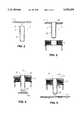
- FIGS. 2 to 7are cross sectional views illustrating the configuration of the stator.
- FIG. 8is an exploded view of the typical electric fan.
- an electric fan in accordance with the present inventioncomprises a housing 1 having a hub 11 provided in the center thereof, an electric board 2 and a stator 3 to be engaged within the housing 1 by a shaft 4, the electric board 2 includes a center hole 21 formed therein for aligning with the hub 11 of the housing 1, the shaft 4 includes a reduced diameter portion 42 engaged with the hole 21 and engaged in the hub 11 by force-fitted engagement, and includes an enlarged portion 41 and an annular flange 43.
- the stator 3includes a center hole 33 for engaging with the enlarged port ion 42 of the shaft 4, the center hole 33 has an inner diameter slightly larger than the outer diameter of the enlarged portion 42 of the shaft 4, the stator further includes an upper polar plate 31 and a lower polar plate 32 each having a center hole 30, 35 formed therein, in which the center hole 30 of the upper polar plate 31 is slightly smaller than the outer diameter of the annular flange 43 of the shaft 4 such that the upper polar plate 31 can be engaged on the annular flange 43 by force-fitted engagement, and the center hole 35 of the lower polar plate 32 is force-fitted on the reduced diameter portion 42 of the shaft 4, the center holes 30, 35 of the polar plates 32, 31 may further be provided with teeth 34 therein for further solidly engaging with the shaft 4, whereby, the stator 3 can be solidly retained between the polar plates 31, 32.
- the teeth 34can be formed by creating several pairs of closely spaced slits in the upper and lower polar plates 31,32. Preferably, there are a total of four pairs of slits, each pair being equally spaced from the others about the inner circumference of the polar plates 31,32.
- the teeth 34are defined between the pairs of slits. According to the preferred arrangement of FIG. 1, the slits are directed radially out from the center holes 30 and 35, and have a longitudinal length parallel to the longitudinal axis of the shaft 4.
- the upper polar plate 31is firstly engaged on the annular flange 43 of the shaft 4 (FIG. 2), the stator 3 is then engaged on the enlarged portion 41 of the shaft 4 (FIG. 3), the lower polar plate 32 and the electric board 2 are then force-fitted on the reduced diameter portion of the shaft 4 (FIGS. 4 and 5), the reduced diameter portion of the shaft 4 is then force-fitted into the hub 11 of the housing 1 (FIGS. 6 and 7) such that the polar plates 31, 32, the stator 3, the electric board 2 and the shaft 4 can be easily engaged and assembled within the housing 1.
- the electric fan in accordance with the present inventionincludes a stator which has a configuration that can be easily engaged and assembled within the housing, such that the electric fan can be easily manufactured.
Landscapes
- Engineering & Computer Science (AREA)
- Power Engineering (AREA)
- Mechanical Engineering (AREA)
- General Engineering & Computer Science (AREA)
- Microelectronics & Electronic Packaging (AREA)
- Structures Of Non-Positive Displacement Pumps (AREA)
Abstract
Description
This is a continuation of application Ser. No. 08/177,519, filed Jan. 4, 1994 which was abandoned upon the filing hereof.
1. Field of the Invention
The present invention relates to an electric fan, and more particularly to a stator of an electric fan.
2. Description of the Prior Art
A typical electric fan is shown in FIG. 8 and comprises a rotor A rotatably supported in an axle of a housing D by a bearing B, and a stator C engaged in the rotor A, however, the axle is integrally formed in the housing D, and the space within the housing D is compact such that it will be very difficult to assemble the stator C and the rotor A within the housing D.
The present invention has arisen to mitigate and/or obviate the afore-described disadvantages of the conventional stators of the electric fans.
The primary objective of the present invention is to provide a stator which can be easily assembled within the housing of the electric fan.
In accordance with one aspect of the invention, there is provided an electric fan comprising a housing including a center having a hub formed therein, a shaft including a first end force-fitted in the hub, a second end having an annular flange formed therein, and a center portion having an enlarged portion formed thereon, an electric board and a lower polar plate force-fitted on the first end of the shaft, a stator engaged on the enlarged portion, and an upper polar plate force-fitted on the annular flange so as to stably retain the stator between the upper polar plate and the lower polar plate. The upper polar plate and the lower polar plate each includes a hole formed therein for engaging with the shaft and having at least one tooth formed therein for solidly engaging with the shaft.
Further objectives and advantages of the present invention will become apparent from a careful reading of the detailed description provided hereinbelow, with appropriate reference to the accompanying drawings.
FIG. 1 is an exploded view of an electric fan in accordance with the present invention;
FIGS. 2 to 7 are cross sectional views illustrating the configuration of the stator; and
FIG. 8 is an exploded view of the typical electric fan.
Referring to the drawings, and initially to FIG. 1, an electric fan in accordance with the present invention comprises a housing 1 having ahub 11 provided in the center thereof, anelectric board 2 and astator 3 to be engaged within the housing 1 by a shaft 4, theelectric board 2 includes a center hole 21 formed therein for aligning with thehub 11 of the housing 1, the shaft 4 includes a reduceddiameter portion 42 engaged with the hole 21 and engaged in thehub 11 by force-fitted engagement, and includes an enlargedportion 41 and anannular flange 43.
Thestator 3 includes acenter hole 33 for engaging with the enlargedport ion 42 of the shaft 4, thecenter hole 33 has an inner diameter slightly larger than the outer diameter of the enlargedportion 42 of the shaft 4, the stator further includes an upperpolar plate 31 and a lowerpolar plate 32 each having acenter hole center hole 30 of the upperpolar plate 31 is slightly smaller than the outer diameter of theannular flange 43 of the shaft 4 such that the upperpolar plate 31 can be engaged on theannular flange 43 by force-fitted engagement, and thecenter hole 35 of the lowerpolar plate 32 is force-fitted on the reduceddiameter portion 42 of the shaft 4, thecenter holes polar plates teeth 34 therein for further solidly engaging with the shaft 4, whereby, thestator 3 can be solidly retained between thepolar plates teeth 34 can be formed by creating several pairs of closely spaced slits in the upper and lowerpolar plates polar plates teeth 34 are defined between the pairs of slits. According to the preferred arrangement of FIG. 1, the slits are directed radially out from thecenter holes
In assembling thestator 3, the upperpolar plate 31 is firstly engaged on theannular flange 43 of the shaft 4 (FIG. 2), thestator 3 is then engaged on the enlargedportion 41 of the shaft 4 (FIG. 3), the lowerpolar plate 32 and theelectric board 2 are then force-fitted on the reduced diameter portion of the shaft 4 (FIGS. 4 and 5), the reduced diameter portion of the shaft 4 is then force-fitted into thehub 11 of the housing 1 (FIGS. 6 and 7) such that thepolar plates stator 3, theelectric board 2 and the shaft 4 can be easily engaged and assembled within the housing 1.
Accordingly, the electric fan in accordance with the present invention includes a stator which has a configuration that can be easily engaged and assembled within the housing, such that the electric fan can be easily manufactured.
Although this invention has been described with a certain degree of particularity, it is to be understood that the present disclosure has been made by way of example only and that numerous changes in the detailed construction and the combination and arrangement of parts may be resorted to without departing from the spirit and scope of the invention as hereinafter claimed.
Claims (4)
1. An electric fan comprising:
a housing including a center having a hub formed therein,
a shaft including a first end force-fitted in said hub, a second end having an annular flange formed therein, and a center portion having an enlarged portion formed thereon, said enlarged portion having a larger outer diameter than that of the annular flange and the first end,
an electric board including a first center hole force-fitted on said first end of said shaft,
a lower polar plate including a second center hole force-fitted on said first end of said shaft,
a stator including a third center hole engaged on said enlarged portion, and
an upper polar plate including a fourth center hole force-fitted on said annular flange so as to stably retain said stator between said upper polar plate and said lower polar plate,
said fourth center hole of said upper polar plate and said second center hole of said lower polar plate each including at least one tooth formed therein for engaging with said shaft so as to be solidly secured to said shaft and so as to solidly retain said stator between said upper and said lower polar plates, and
wherein said at least one tooth is defined by at least two pairs of slits which extend radially out from each of said fourth center hole and said second center hole, said at least two pairs of slits having a longitudinal length parallel to a longitudinal axis of the shaft, said at least one tooth being defined between said at least two pairs of slits.
2. The electric fan of claim 1, wherein said enlarged portion is formed integrally with said shaft to prevent relative rotation between the shaft and enlarged portion and to facilitate assembly of the electric fan.
3. An electric fan comprising:
a housing including a center having a hub formed therein,
a shaft including a first end force-fitted in said hub, a second end having an annular flange formed therein, and a center portion having an enlarged portion formed thereon, said enlarged portion having a larger outer diameter than that of the annular flange and the first end,
an electric board including a first center hole force-fitted on said first end of said shaft,
a lower polar plate including a second center hole force-fitted on said first end of said shaft,
a stator including a third center hole engaged on said enlarged portion, and
an upper polar plate including a fourth center hole force-fitted on said annular flange so as to stably retain said stator between said upper polar plate and said lower polar plate,
said fourth center hole of said upper polar plate and said second center hole of said lower polar plate each including at least one tooth formed therein for engaging with said shaft so as to be solidly secured to said shaft and so as to solidly retain said stator between said upper and said lower polar plates, and
wherein said at least one tooth comprises four teeth in each of said fourth center hole and said second center hole, said four teeth being defined in each of said fourth and second center holes by four pairs of slits, said four pairs of slits being equally spaced about the fourth center hole and about the second center hole and extending radially out therefrom, said four pairs of slits having a longitudinal length parallel to a longitudinal axis of the shaft.
4. The electric fan of claim 3, wherein said enlarged portion is formed integrally with said shaft to prevent relative rotation between the shaft and enlarged portion and to facilitate assembly of the electric fan.
Priority Applications (3)
| Application Number | Priority Date | Filing Date | Title |
|---|---|---|---|
| GB9400089AGB2285541B (en) | 1994-01-05 | 1994-01-05 | Electric fans and method of assembly thereof |
| FR9400262AFR2714935B1 (en) | 1994-01-05 | 1994-01-12 | Electric fan. |
| US08/369,298US5492458A (en) | 1994-01-04 | 1995-01-06 | Stator of electric fan |
Applications Claiming Priority (4)
| Application Number | Priority Date | Filing Date | Title |
|---|---|---|---|
| US17751994A | 1994-01-04 | 1994-01-04 | |
| GB9400089AGB2285541B (en) | 1994-01-05 | 1994-01-05 | Electric fans and method of assembly thereof |
| FR9400262AFR2714935B1 (en) | 1994-01-05 | 1994-01-12 | Electric fan. |
| US08/369,298US5492458A (en) | 1994-01-04 | 1995-01-06 | Stator of electric fan |
Related Parent Applications (1)
| Application Number | Title | Priority Date | Filing Date |
|---|---|---|---|
| US17751994AContinuation | 1994-01-04 | 1994-01-04 |
Publications (1)
| Publication Number | Publication Date |
|---|---|
| US5492458Atrue US5492458A (en) | 1996-02-20 |
Family
ID=27252858
Family Applications (1)
| Application Number | Title | Priority Date | Filing Date |
|---|---|---|---|
| US08/369,298Expired - LifetimeUS5492458A (en) | 1994-01-04 | 1995-01-06 | Stator of electric fan |
Country Status (3)
| Country | Link |
|---|---|
| US (1) | US5492458A (en) |
| FR (1) | FR2714935B1 (en) |
| GB (1) | GB2285541B (en) |
Cited By (40)
| Publication number | Priority date | Publication date | Assignee | Title |
|---|---|---|---|---|
| US5654598A (en)* | 1995-12-14 | 1997-08-05 | Siemens Electric Limited | Brushless motor with inside mounted single bearing |
| US5663604A (en)* | 1994-12-28 | 1997-09-02 | Nidec Corporation | Brushless motor |
| US5744893A (en)* | 1996-11-25 | 1998-04-28 | Industrial Technology Research Institute | Brushless motor stator design |
| FR2755315A1 (en)* | 1996-10-29 | 1998-04-30 | Sunonwealth Electr Mach Ind Co | STATOR WINDING STRUCTURE FOR MOTOR AND METHOD OF MAKING SAME |
| US5847524A (en)* | 1996-12-05 | 1998-12-08 | General Electric Company | Constant speed control for a motor |
| US5962938A (en) | 1997-10-21 | 1999-10-05 | General Electric Company | Motor with external rotor |
| US5997265A (en)* | 1997-09-23 | 1999-12-07 | D-Link Corporation | Bearing structure for radiating fans |
| US6000919A (en)* | 1999-02-17 | 1999-12-14 | Hsieh; Hsin-Mao | Fan with reduced thickness |
| US6118198A (en) | 1999-03-25 | 2000-09-12 | General Electric Company | Electric motor with ice out protection |
| US6133666A (en) | 1999-03-25 | 2000-10-17 | General Electric Company | Electric motor with a stator including a central locator |
| US6147465A (en) | 1999-03-25 | 2000-11-14 | General Electric Company | Microprocessor controlled single phase motor with external rotor having integral fan |
| US6158985A (en)* | 1998-10-07 | 2000-12-12 | Sanyo Denki Co., Ltd. | Air fan including waterproof structure |
| EP1075072A1 (en)* | 1999-03-16 | 2001-02-07 | Sunonwealth Electric Machine Industry Co., Ltd. | Brushless DC motor and its stator |
| US6232687B1 (en) | 1999-03-25 | 2001-05-15 | General Electric Company | Electric motor having snap connection assembly |
| US6239532B1 (en) | 1996-12-05 | 2001-05-29 | General Electric Company | Motor with external rotor |
| US6246140B1 (en) | 2000-03-09 | 2001-06-12 | Sunonwealth Electric Machine Industry | Pivotal structure for a motor rotor |
| US6270325B1 (en)* | 1999-09-14 | 2001-08-07 | Hsieh Hsin-Mao | Magnetically assembled cooling fan |
| US6271609B1 (en) | 1999-03-25 | 2001-08-07 | General Electric Company | Programmable electric motor and method of assembly |
| US6309190B1 (en)* | 2000-01-28 | 2001-10-30 | Yen Sun Technic Industrial Corporation | Shaft supporting structure for an axial fan |
| US20010036416A1 (en)* | 2000-04-28 | 2001-11-01 | Minebea Kabushiki-Kaisha | Blower |
| US6315529B1 (en)* | 2000-05-04 | 2001-11-13 | Tranyoung Technology Corp. | Cooling fan with anti deflection arrangement |
| US6320291B1 (en)* | 1999-08-18 | 2001-11-20 | Delta Electronics, Inc. | Construction of motor |
| US6400053B1 (en)* | 2000-10-12 | 2002-06-04 | Sunonwealth Electric Machine Industry Co., Ltd. | Axle balance plates for D.C brushless motor |
| US20020110456A1 (en)* | 2001-01-19 | 2002-08-15 | Gate S.P.A. | Electric fan |
| FR2827091A1 (en)* | 2001-05-07 | 2003-01-10 | Sunonwealth Electr Mach Ind Co | Stator assembly for motor, has lower and upper pole plates with radial poles that include magnetic pole faces having same or different length |
| US6612814B2 (en)* | 2002-01-29 | 2003-09-02 | Ideal Elethermal Inc. | Electrical fan having an oil retaining ring to prevent loss and evaporation of lubricant oil |
| US20040201298A1 (en)* | 2003-04-08 | 2004-10-14 | Sunonwealth Electric Machine Industry Co., Ltd. | Combination of a base and an axle tube for a fan motor |
| DE19853330B4 (en)* | 1998-11-04 | 2005-01-05 | Sunonwealth Electric Machine Industry Co., Ltd. | Miniature Wärmeableitgebläseanordnung |
| US6841957B2 (en)* | 1998-01-23 | 2005-01-11 | Conair Rotron, Inc. | Low profile motor |
| EP1684408A1 (en)* | 2005-01-21 | 2006-07-26 | Harman Becker Automotive Systems GmbH | Electric motor system |
| US20070178720A1 (en)* | 2006-01-31 | 2007-08-02 | Nidec Corporation | Electric Fan |
| US20100074747A1 (en)* | 2008-09-22 | 2010-03-25 | Chien-Chun Yu | Mini axial fan with an improved core shaft structure |
| US20100172095A1 (en)* | 2009-01-05 | 2010-07-08 | Macdonald Mark | Crossflow blower apparatus and system |
| US20110305507A1 (en)* | 2010-06-15 | 2011-12-15 | Changde Li | Cooling fan bearing retainer ring structure |
| US20120002368A1 (en)* | 2010-06-30 | 2012-01-05 | Broili Ben M | Integrated crossflow blower motor apparatus and system |
| US20120039730A1 (en)* | 2010-08-13 | 2012-02-16 | Asia Vital Components Co., Ltd. | Central tubular structure of a shaft seat and fan device thereof |
| US20120039729A1 (en)* | 2010-08-16 | 2012-02-16 | Alex Horng | Motor and Cooling Fan utilizing the same |
| US20130234541A1 (en)* | 2012-03-08 | 2013-09-12 | Stainless Motors, Inc. | Electric Motor Configured for Facilitated Washability |
| US20160025104A1 (en)* | 2014-07-28 | 2016-01-28 | Asia Vital Components Co., Ltd. | Annular fan wiring structure |
| US20240164051A1 (en)* | 2022-11-15 | 2024-05-16 | Delta Electronics, Inc. | Fan module |
Citations (10)
| Publication number | Priority date | Publication date | Assignee | Title |
|---|---|---|---|---|
| US869901A (en)* | 1907-01-17 | 1907-11-05 | Henry Hahn | Tappet. |
| US2742223A (en)* | 1952-12-13 | 1956-04-17 | Font Eduardo Soler | Electric propeller fans and the like |
| US4360498A (en)* | 1981-04-14 | 1982-11-23 | Herder Robert O | Sectional lined end box for chemical cell |
| US4376333A (en)* | 1978-06-21 | 1983-03-15 | Hitachi, Ltd. | Method of joining members of metal by forced insertion |
| US4959571A (en)* | 1988-03-11 | 1990-09-25 | Mitsubishi Denki Kabushiki Kaisha | Axial-flow fan with tapered hub and duct |
| US4987331A (en)* | 1989-03-06 | 1991-01-22 | Alex Horng | Non-brush D.C. motor with an improved stator |
| US5019735A (en)* | 1990-08-07 | 1991-05-28 | Lee Jen J | Motor construction for an electric fan |
| US5099181A (en)* | 1991-05-03 | 1992-03-24 | Canon K N Hsu | Pulse-width modulation speed controllable DC brushless cooling fan |
| US5272930A (en)* | 1991-06-07 | 1993-12-28 | Nippon Piston Ring Co., Ltd. | Mechanical element having a shaft pressure-fitted into an engaging member and its manufacturing method |
| US5288216A (en)* | 1990-11-23 | 1994-02-22 | U.S. Philips Corporation | Fan unit for generating gas streams |
Family Cites Families (7)
| Publication number | Priority date | Publication date | Assignee | Title |
|---|---|---|---|---|
| US3378192A (en)* | 1966-12-20 | 1968-04-16 | Imc Magneties Corp | Means for securing the impeller to the motor of an electrically driven fan |
| DE2912802C2 (en)* | 1979-03-30 | 1983-11-10 | Siemens AG, 1000 Berlin und 8000 München | Arrangement for interconnecting the winding ends of the stator winding with an external connecting cable in an external rotor motor |
| US4882511A (en)* | 1984-06-01 | 1989-11-21 | Papst-Motoren Gmbh & Co. Kg | Brushless three-phase D.C. motor |
| DE3871480D1 (en)* | 1987-10-01 | 1992-07-02 | Seiko Electronic Components | AXIAL FAN. |
| US4965686A (en)* | 1989-03-31 | 1990-10-23 | Raymond Engineering Inc. | Disc drive assembly for magnetic disc memory unit |
| CA2037852C (en)* | 1991-02-26 | 1993-06-29 | Alex Horng | Brushless d.c. motor with plastic stator base |
| GB2269058B (en)* | 1992-07-27 | 1996-03-06 | Alex Horng | Industrial heat dissipating electric fan |
- 1994
- 1994-01-05GBGB9400089Apatent/GB2285541B/ennot_activeExpired - Fee Related
- 1994-01-12FRFR9400262Apatent/FR2714935B1/ennot_activeExpired - Fee Related
- 1995
- 1995-01-06USUS08/369,298patent/US5492458A/ennot_activeExpired - Lifetime
Patent Citations (11)
| Publication number | Priority date | Publication date | Assignee | Title |
|---|---|---|---|---|
| US869901A (en)* | 1907-01-17 | 1907-11-05 | Henry Hahn | Tappet. |
| US2742223A (en)* | 1952-12-13 | 1956-04-17 | Font Eduardo Soler | Electric propeller fans and the like |
| US4376333A (en)* | 1978-06-21 | 1983-03-15 | Hitachi, Ltd. | Method of joining members of metal by forced insertion |
| US4360498A (en)* | 1981-04-14 | 1982-11-23 | Herder Robert O | Sectional lined end box for chemical cell |
| US4959571A (en)* | 1988-03-11 | 1990-09-25 | Mitsubishi Denki Kabushiki Kaisha | Axial-flow fan with tapered hub and duct |
| US4987331A (en)* | 1989-03-06 | 1991-01-22 | Alex Horng | Non-brush D.C. motor with an improved stator |
| US5019735A (en)* | 1990-08-07 | 1991-05-28 | Lee Jen J | Motor construction for an electric fan |
| US5288216A (en)* | 1990-11-23 | 1994-02-22 | U.S. Philips Corporation | Fan unit for generating gas streams |
| US5099181A (en)* | 1991-05-03 | 1992-03-24 | Canon K N Hsu | Pulse-width modulation speed controllable DC brushless cooling fan |
| US5272930A (en)* | 1991-06-07 | 1993-12-28 | Nippon Piston Ring Co., Ltd. | Mechanical element having a shaft pressure-fitted into an engaging member and its manufacturing method |
| US5272930B1 (en)* | 1991-06-07 | 1997-09-23 | Nippon Piston Ring Co Ltd | Mechanical element having a shaft pressure-fitted into an engaging member and its manufacturing method |
Cited By (52)
| Publication number | Priority date | Publication date | Assignee | Title |
|---|---|---|---|---|
| US5663604A (en)* | 1994-12-28 | 1997-09-02 | Nidec Corporation | Brushless motor |
| US5654598A (en)* | 1995-12-14 | 1997-08-05 | Siemens Electric Limited | Brushless motor with inside mounted single bearing |
| FR2755315A1 (en)* | 1996-10-29 | 1998-04-30 | Sunonwealth Electr Mach Ind Co | STATOR WINDING STRUCTURE FOR MOTOR AND METHOD OF MAKING SAME |
| US5744893A (en)* | 1996-11-25 | 1998-04-28 | Industrial Technology Research Institute | Brushless motor stator design |
| US5847524A (en)* | 1996-12-05 | 1998-12-08 | General Electric Company | Constant speed control for a motor |
| US5982122A (en)* | 1996-12-05 | 1999-11-09 | General Electric Company | Capacitively powered motor and constant speed control therefor |
| US6239532B1 (en) | 1996-12-05 | 2001-05-29 | General Electric Company | Motor with external rotor |
| US5997265A (en)* | 1997-09-23 | 1999-12-07 | D-Link Corporation | Bearing structure for radiating fans |
| US5962938A (en) | 1997-10-21 | 1999-10-05 | General Electric Company | Motor with external rotor |
| US6286199B1 (en) | 1997-10-21 | 2001-09-11 | General Electric Company | Method for assembly of motor with external rotor |
| US6841957B2 (en)* | 1998-01-23 | 2005-01-11 | Conair Rotron, Inc. | Low profile motor |
| US6158985A (en)* | 1998-10-07 | 2000-12-12 | Sanyo Denki Co., Ltd. | Air fan including waterproof structure |
| DE19853330B4 (en)* | 1998-11-04 | 2005-01-05 | Sunonwealth Electric Machine Industry Co., Ltd. | Miniature Wärmeableitgebläseanordnung |
| US6000919A (en)* | 1999-02-17 | 1999-12-14 | Hsieh; Hsin-Mao | Fan with reduced thickness |
| JP3431854B2 (en) | 1999-03-16 | 2003-07-28 | 建準電機工業股▲分▼有限公司 | Brushless DC motor and its stator |
| EP1075072A1 (en)* | 1999-03-16 | 2001-02-07 | Sunonwealth Electric Machine Industry Co., Ltd. | Brushless DC motor and its stator |
| US6232687B1 (en) | 1999-03-25 | 2001-05-15 | General Electric Company | Electric motor having snap connection assembly |
| US6271609B1 (en) | 1999-03-25 | 2001-08-07 | General Electric Company | Programmable electric motor and method of assembly |
| US6118198A (en) | 1999-03-25 | 2000-09-12 | General Electric Company | Electric motor with ice out protection |
| US6133666A (en) | 1999-03-25 | 2000-10-17 | General Electric Company | Electric motor with a stator including a central locator |
| US6147465A (en) | 1999-03-25 | 2000-11-14 | General Electric Company | Microprocessor controlled single phase motor with external rotor having integral fan |
| US6320291B1 (en)* | 1999-08-18 | 2001-11-20 | Delta Electronics, Inc. | Construction of motor |
| US6270325B1 (en)* | 1999-09-14 | 2001-08-07 | Hsieh Hsin-Mao | Magnetically assembled cooling fan |
| US6309190B1 (en)* | 2000-01-28 | 2001-10-30 | Yen Sun Technic Industrial Corporation | Shaft supporting structure for an axial fan |
| US6246140B1 (en) | 2000-03-09 | 2001-06-12 | Sunonwealth Electric Machine Industry | Pivotal structure for a motor rotor |
| US6916160B2 (en) | 2000-04-28 | 2005-07-12 | Minebea Kabushiki-Kaisha | Axial electric fan blower with electric components housing sealed from moisture, dirt and dust or other harmful gas |
| EP1150017A3 (en)* | 2000-04-28 | 2003-01-15 | Minebea Kabushiki Kaisha | Blower |
| US20010036416A1 (en)* | 2000-04-28 | 2001-11-01 | Minebea Kabushiki-Kaisha | Blower |
| US6315529B1 (en)* | 2000-05-04 | 2001-11-13 | Tranyoung Technology Corp. | Cooling fan with anti deflection arrangement |
| US6400053B1 (en)* | 2000-10-12 | 2002-06-04 | Sunonwealth Electric Machine Industry Co., Ltd. | Axle balance plates for D.C brushless motor |
| US20020110456A1 (en)* | 2001-01-19 | 2002-08-15 | Gate S.P.A. | Electric fan |
| FR2827091A1 (en)* | 2001-05-07 | 2003-01-10 | Sunonwealth Electr Mach Ind Co | Stator assembly for motor, has lower and upper pole plates with radial poles that include magnetic pole faces having same or different length |
| US6612814B2 (en)* | 2002-01-29 | 2003-09-02 | Ideal Elethermal Inc. | Electrical fan having an oil retaining ring to prevent loss and evaporation of lubricant oil |
| US20040201298A1 (en)* | 2003-04-08 | 2004-10-14 | Sunonwealth Electric Machine Industry Co., Ltd. | Combination of a base and an axle tube for a fan motor |
| EP1684408A1 (en)* | 2005-01-21 | 2006-07-26 | Harman Becker Automotive Systems GmbH | Electric motor system |
| US20080030161A1 (en)* | 2005-01-21 | 2008-02-07 | Michael Ludwig | Electric motor system |
| US7439698B2 (en) | 2005-01-21 | 2008-10-21 | Harman International Industries, Incorporated | Electric motor system |
| US20070178720A1 (en)* | 2006-01-31 | 2007-08-02 | Nidec Corporation | Electric Fan |
| US20100074747A1 (en)* | 2008-09-22 | 2010-03-25 | Chien-Chun Yu | Mini axial fan with an improved core shaft structure |
| US10914308B2 (en) | 2009-01-05 | 2021-02-09 | Intel Corporation | Crossflow blower apparatus and system |
| US20100172095A1 (en)* | 2009-01-05 | 2010-07-08 | Macdonald Mark | Crossflow blower apparatus and system |
| US20110305507A1 (en)* | 2010-06-15 | 2011-12-15 | Changde Li | Cooling fan bearing retainer ring structure |
| US20120002368A1 (en)* | 2010-06-30 | 2012-01-05 | Broili Ben M | Integrated crossflow blower motor apparatus and system |
| US9249803B2 (en)* | 2010-06-30 | 2016-02-02 | Intel Corporation | Integrated crossflow blower motor apparatus and system |
| US8651830B2 (en)* | 2010-08-13 | 2014-02-18 | Asia Vital Components Co., Ltd. | Central tubular structure of a shaft seat and fan device thereof |
| US20120039730A1 (en)* | 2010-08-13 | 2012-02-16 | Asia Vital Components Co., Ltd. | Central tubular structure of a shaft seat and fan device thereof |
| US20120039729A1 (en)* | 2010-08-16 | 2012-02-16 | Alex Horng | Motor and Cooling Fan utilizing the same |
| US8506264B2 (en)* | 2010-08-16 | 2013-08-13 | Sunonwealth Electric Machine Industry Co., Ltd. | Motor and cooling fan with a circuit board having a heat-conducting insulator |
| US20130234541A1 (en)* | 2012-03-08 | 2013-09-12 | Stainless Motors, Inc. | Electric Motor Configured for Facilitated Washability |
| US9197109B2 (en)* | 2012-03-08 | 2015-11-24 | Stainless Motors, Inc. | Electric motor configured for facilitated washability |
| US20160025104A1 (en)* | 2014-07-28 | 2016-01-28 | Asia Vital Components Co., Ltd. | Annular fan wiring structure |
| US20240164051A1 (en)* | 2022-11-15 | 2024-05-16 | Delta Electronics, Inc. | Fan module |
Also Published As
| Publication number | Publication date |
|---|---|
| FR2714935B1 (en) | 1996-03-01 |
| GB2285541B (en) | 1997-04-16 |
| GB2285541A (en) | 1995-07-12 |
| FR2714935A1 (en) | 1995-07-13 |
| GB9400089D0 (en) | 1994-03-02 |
Similar Documents
| Publication | Publication Date | Title |
|---|---|---|
| US5492458A (en) | Stator of electric fan | |
| US4682065A (en) | Molded plastic motor housing with integral stator mounting and shaft journalling projection | |
| US5893705A (en) | Integrated motor and blower apparatus having two back-to-back coupled rotors | |
| US4603273A (en) | Dynamoelectric machine with extended cleat assembly | |
| US6617736B1 (en) | Axle tube structure for a motor | |
| US20050260065A1 (en) | Blower | |
| US6002186A (en) | Electric stepper motor having a cylindrical magnetic rotor with a pair of cups made of magnetic material | |
| EP1942280A3 (en) | Compressor unit comprising a centrifugical compressor and an electric motor | |
| US5019735A (en) | Motor construction for an electric fan | |
| US20040160135A1 (en) | Single magnetic conductive plate structure for forming a single pole plate brushless dc motor | |
| US6538355B1 (en) | Supporting structure for a rotor | |
| US5967763A (en) | Positioning devices for a sensor element of a miniature fan | |
| AU2002235524A1 (en) | Design for frameless cartridge motors | |
| US6048173A (en) | Engagement of blade brackets and the motor casing for a ceiling fan | |
| EP1096152A3 (en) | Turbo molecular pump | |
| US7354254B2 (en) | Compact vacuum pump | |
| US11677285B2 (en) | Outer rotor type motor capable of improving withstand load performance in relation to external load and lifespan | |
| US20100259115A1 (en) | Motor | |
| US6724106B1 (en) | Miniature brushless dc fan motor | |
| US6140736A (en) | Anti-loosening outer rotor means for high-torque outer-rotor type electric motor | |
| US6648511B2 (en) | Electric motor bearing system and journal | |
| US4009970A (en) | Resilient fan hub | |
| JP4244325B2 (en) | Rotating electrical machine rotor | |
| US5106277A (en) | Drive connection for fuel pump rotor | |
| US6739814B1 (en) | Retaining ring for a rotor |
Legal Events
| Date | Code | Title | Description |
|---|---|---|---|
| STCF | Information on status: patent grant | Free format text:PATENTED CASE | |
| AS | Assignment | Owner name:SUNONWEALTH ELECTRIC MACHINE INDUSTRY CO., LTD., T Free format text:ASSIGNMENT OF ASSIGNORS INTEREST;ASSIGNOR:HORNG, ALEX;REEL/FRAME:008842/0046 Effective date:19971020 | |
| FEPP | Fee payment procedure | Free format text:PAT HLDR NO LONGER CLAIMS SMALL ENT STAT AS INDIV INVENTOR (ORIGINAL EVENT CODE: LSM1); ENTITY STATUS OF PATENT OWNER: LARGE ENTITY | |
| FPAY | Fee payment | Year of fee payment:4 | |
| FEPP | Fee payment procedure | Free format text:PAYOR NUMBER ASSIGNED (ORIGINAL EVENT CODE: ASPN); ENTITY STATUS OF PATENT OWNER: LARGE ENTITY | |
| FPAY | Fee payment | Year of fee payment:8 | |
| FPAY | Fee payment | Year of fee payment:12 |