US5491477A - Anti-rotation mechanism for direct manipulation position input controller for computer - Google Patents
Anti-rotation mechanism for direct manipulation position input controller for computerDownload PDFInfo
- Publication number
- US5491477A US5491477AUS08/120,678US12067893AUS5491477AUS 5491477 AUS5491477 AUS 5491477AUS 12067893 AUS12067893 AUS 12067893AUS 5491477 AUS5491477 AUS 5491477A
- Authority
- US
- United States
- Prior art keywords
- gripable
- movement
- housing
- pantagraph
- plate
- Prior art date
- Legal status (The legal status is an assumption and is not a legal conclusion. Google has not performed a legal analysis and makes no representation as to the accuracy of the status listed.)
- Expired - Lifetime
Links
Images


Classifications
- G—PHYSICS
- G06—COMPUTING OR CALCULATING; COUNTING
- G06F—ELECTRIC DIGITAL DATA PROCESSING
- G06F3/00—Input arrangements for transferring data to be processed into a form capable of being handled by the computer; Output arrangements for transferring data from processing unit to output unit, e.g. interface arrangements
- G06F3/01—Input arrangements or combined input and output arrangements for interaction between user and computer
- G06F3/03—Arrangements for converting the position or the displacement of a member into a coded form
- G06F3/033—Pointing devices displaced or positioned by the user, e.g. mice, trackballs, pens or joysticks; Accessories therefor
- G06F3/0354—Pointing devices displaced or positioned by the user, e.g. mice, trackballs, pens or joysticks; Accessories therefor with detection of 2D relative movements between the device, or an operating part thereof, and a plane or surface, e.g. 2D mice, trackballs, pens or pucks
- G06F3/03548—Sliders, in which the moving part moves in a plane
Definitions
- This inventionrelates to a device for controlling the position of objects on the display of a computer system, and more particularly, to an improved control device for manipulating such objects while preventing rotation which causes skewed movement of such objects.
- Standard control devices for manipulating the position of objects on the display screen of a computer systeminclude cursor positioning keys, mouse systems, track balls and joy sticks.
- cursor positioning keysWith a mouse, the movement of the mouse across a pad translates to the movement of a cursor or other object across the computer display screen in the same direction in most circumstances.
- the rotation of a trackballwhile remaining in place, creates an equivalent movement of a cursor, or the like, across the computer display screen.
- the angling of the wristmay be important for the drawing techniques or styles which they use. For example, in using paint brushes, colored pencils, chalk or charcoal, sometimes the artist angles his or her wrist to create the desired brush stroke or the like. However, if the artist were to angle the wrist while using a prior art mouse, the line would not go where the mouse goes, but would go at an angle instead. Also, for all users, there is a natural tendency to curl inward the wrist toward the body, whether with the right or left hand.
- pantagraphwhich has been used in the graphics industry for a number of years to trace and enlarge a picture, drawing or the like.
- the deviceconsists of a pointer which is coupled through a connector to a pen, where the coupling mechanism enable the enlargement of the image traced by the pointer.
- These pantagraph deviceshave not heretofore been adapted for any use on a computer system.
- the present inventioncomprises a pantagraph-like device which couples a control knob to a computer system.
- the devicedetects the movement of the control knob and translates it to the computer system so that movement of the control knob causes a cursor or other object on a computer screen to move.
- the pantagraph-like deviceprevents the control knob from rotating, so that under all conditions, movement in the x and y planes causes equivalent movement of the object on the computer screen without any skewing.
- the inventionmaintains the true x and y plane movements by preventing rotation of the control knob relative to the movement sensing means.
- the devicealso permits fine control of the cursor or other computer screen object when there is limited movement of the cursor because the control mechanism can be "ratcheted” by picking it up off the surface, pulling it back and sliding it along the surface again.
- the present inventioncomprises a plate with a border and a control knob disposed on the plate.
- the control knobis connected to any type of position sensing mechanisms including a linear, rotary or optical sensing mechanism, all of which are known in the art.
- the control knobcan be any useful shape, including a pen shape, which artists may find very comfortable.
- the entire devicecan be disposed within a small area, and therefore, can be used even with a portable computer having limited desk space.
- the pantagraph-like coupling devicehas two sets of generally parallel arms, one set of arms being coupled at one end to the control knob or plate on which the control knob is fixed, and the other end of said first set of arms being coupled to a regular geometric plate, such as a square plate, with each one of the first set of arms being connected to an diagonally opposite corner of the square plate.
- the other set of armsis connected to an anchor means or other fixed position device at one end, and at the other end, each of the second set of arms is connected to the two remaining diagonally opposing corners of the regular geometric plate. If the regular geometric plate is a circle, then each set of arms is connected to said circular plate such that an imaginary line connecting the connection points of said arms to said plate passes through the center of the circular plate.
- the sensing devicecan either be disposed directly under the control knob, in which case, it may be directly connected to the control knob, or it can be disposed remote from the control knob.
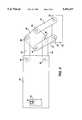
- FIG. 1is a side perspective illustration of one embodiment of the present invention being operated by a user.
- FIG. 2is a top plan view of the anti-rotation device of the present invention in a partial cut-away view illustrating the operation of the invention in two positions.
- FIG. 3is a side sectional view of the present invention taken through lines 2--2 of FIG. 2, and illustrating one type of position detection device which may be used in conjunction with the present invention.
- FIG. 4is an exploded view of an alternative embodiment of the present invention which utilizes an optical sensing device for position detection.
- FIG. 5is an enlarged top plan view of the embodiment of the present invention shown in FIG. 2.
- FIG. 6is an enlarged top plan view of an alternative embodiment of the present invention.
- FIG. 7is an enlarged top plan view of the embodiment of the present invention shown in FIG. 6 with the control knob in a different position.
- the present inventionas shown generally in FIG. 1 comprises an input device for a computer system for inputting the position of objects, such as a cursor or mark, on a computer screen.
- the computeris a conventional personal computer 11 or the equivalent and may comprise a video screen 13 and a computer housing 15, or any other arrangement well-known in the art.
- the device 10can be made integral with a keyboard (not shown) of a computer in the same way that a track ball can be incorporated into a computer system. Alternatively, the device may be a separate stand-alone device.
- FIG. 2is a partially cutaway view of the input device of the present invention installed in a housing 14 which can be a special housing for a stand-alone version of the device or a portion of a keyboard for a more compact version of the device.
- the deviceWhen installed in a keyboard the device includes a control knob 16 with a button means 26, attached to a plate 18, the plate 18 being slidably attached to the interior of the housing 14, and a border 20 defining an area of slidable movement of the control knob 16.
- the plate 18is preferably sized so that no matter where the control knob is positioned within the border 20, the plate entirely covers the area within the border 20. This ensures that there is no gap, and keeps the area under the plate generally clean.
- the border 20is defined by top border member 21a, bottom border member 21b, left side border member 21c and right side border member 21d.
- arrow 1depicts the movement of the plate 18 from a center position to a far right position.
- arrow 2depicts the movement of the plate 18 to a lower left position.
- the control knob 16comprises a body portion 24 and a button means 26.
- the body portion 24can be any shape but is preferably a shape which is easy to grip.
- the button meanscan either be raised, flush or recessed in the body portion 24, and serves as a button as is typically found on a mouse, as is known in the art.
- the plate 18is attached by two pivot means 28 and 30 to arms 32 and 34 respectively, which are attached on the underside of the plate 18.
- the opposite ends of arms 32 and 34are attached to pantagraph plate 36, and specifically are attached at pivots 38 and 40 on diagonally opposing sides of pantagraph plate 36.
- the arms 32 and 34are attached to pivots 38 and 40 on the underside of pantagraph plate 36.
- Arms 42 and 44are attached to the remaining two corners of pantagraph plate 36 at pivots 46 and 48.
- the other ends of arms 42 and 44are coupled at pivots 56 and 58, respectively, to mount 50 which is secured in position to the housing.
- the plate 18ais attached to arms 32a and 34a respectively.
- the opposite ends of arms 32a and 34aare attached to pantagraph plate 36a.
- Arms 42a and 44aare attached to the remaining two corners of pantagraph plate 36a.
- the other ends of arms 42a and 44aare coupled to mount 50 which is secured in position to the housing.
- the plate 18bis attached to arms 32b and 34b respectively.
- the opposite ends of arms 32b and 34bare attached to pantagraph plate 36b.
- Arms 42b and 44bare attached to the remaining two corners of pantagraph plate 36b.
- the other ends of arms 42a and 44aare coupled to mount 50 which is secured in position to the housing.
- FIGS. 6 and 7show another embodiment of the present invention in which the pantagraph plate 66a and 66b is round rather than rectangular.
- the plate 48ais attached to arms 62a and 64a respectively.
- the opposite ends of arms 62a and 64aare attached to pantagraph plate 66a .
- Arms 72a and 74aare attached to the remaining two corners of pantagraph plate 66a .
- the other ends of arms 72a and 74aare coupled to mount 80 which is secured in position to the housing.
- the plate 48bis attached to arms 62b and 64b respectively.
- the opposite ends of arms 62b and 64bare attached to pantagraph plate 66b .
- Arms 72b and 74bare attached to the remaining two corners of pantagraph plate 66b .
- the other ends of arms 72a and 74aare coupled to mount 80 which is secured in position to the housing.
- FIGS. 3 and 4show alternative position sensing devices. It will be appreciated by persons of skill in the art that any type of position sensing device may be utilized in the present invention without departing from the spirit and scope of the present invention. It is also beyond the scope of this application to describe, in detail, the operation of position sensing devices since such devices are well known in the prior art.
- the critical feature of the present inventionis the association of a fixed position relative to the control knob with the position sensing device so that the movement of the control knob translates to a comparable movement of a cursor or other indicator on the computer screen.
- FIG. 3specifically depicts one embodiment where a mechanical mouse device is used to control the cursor movement. It will be obvious to any one skilled in the art that many modifications can be made to this structure without departing from the spirit and scope of the present invention.
- the plate 18overlies and engages a ball 52 so that movement of the plate in any direction x, y or anywhere through the x-y axis causes a comparable rotation of the ball 52.
- sensing wheel 54Sitting below the ball is sensing wheel 54 which senses the rotation of the ball 52 in one direction, and a second sensing wheel (not shown), which senses rotation in a perpendicular direction.
- sensing wheel 54Sitting below the ball is sensing wheel 54 which senses the rotation of the ball 52 in one direction, and a second sensing wheel (not shown), which senses rotation in a perpendicular direction.
- Such sensing devicesare well known in the art.
- the ball 52remains stationary relative to the plate, except for the rotation described above, so that any and all movement of the plate 18 translates precisely to the same mount of rotation of the ball 52.
- the plate 52is held to move in the x and y planes by the arm 34 and the arm 32 (not shown) being attached to the plate 36, which in turn is attached to the housing by bracket 50 through arms 42 and 44.
- the position sensing deviceis optical rather than mechanical.
- Such devicesare well known in the prior art, and operate on the principal of counting the number of grid lines or other markers which pass an optical eye.
- the present inventioncomprises a sensing device 82 having an eye 84 for detecting the relative movement of the plate 86 relative to the eye 84, the sensing device being fixed in position relative to the computer.
- FIG. 4also illustrates that the control knob 88 may be rotatably disposed in the plate 86. This facilitates use with either hand of a user for improved comfort without skewing the movement of the cursor on the computer screen.
- the plate 86is connected to arms 89 and 90 which are connected on opposite sides to pantagraph plate 92, with the other two opposing sides of pantagraph plate 92 being connected to arms 93 and 94 which are attached to bracket 96.
- the position sensing apparatusbeing directly associated with the plate, such arrangement is not required, and the position sensing apparatus can be disposed in a position remote from the plate as long as the sensing apparatus is arranged to sense the relative movement of the plate to the system.
- the sensing apparatusmay be an arm containing an optical eye being attached to the underside of the plate and a grid being disposed adjacent the eye in a remote portion of the device.
- the movement of the cursor or other screen pointerdoes not need to be linear with the movement of the control knob, and it may be scaled up or down depending upon whether fine or gross movements are required for the particular task being performed.
Landscapes
- Engineering & Computer Science (AREA)
- General Engineering & Computer Science (AREA)
- Theoretical Computer Science (AREA)
- Human Computer Interaction (AREA)
- Physics & Mathematics (AREA)
- General Physics & Mathematics (AREA)
- Position Input By Displaying (AREA)
Abstract
Description
Claims (18)
Priority Applications (1)
| Application Number | Priority Date | Filing Date | Title |
|---|---|---|---|
| US08/120,678US5491477A (en) | 1993-09-13 | 1993-09-13 | Anti-rotation mechanism for direct manipulation position input controller for computer |
Applications Claiming Priority (1)
| Application Number | Priority Date | Filing Date | Title |
|---|---|---|---|
| US08/120,678US5491477A (en) | 1993-09-13 | 1993-09-13 | Anti-rotation mechanism for direct manipulation position input controller for computer |
Publications (1)
| Publication Number | Publication Date |
|---|---|
| US5491477Atrue US5491477A (en) | 1996-02-13 |
Family
ID=22391865
Family Applications (1)
| Application Number | Title | Priority Date | Filing Date |
|---|---|---|---|
| US08/120,678Expired - LifetimeUS5491477A (en) | 1993-09-13 | 1993-09-13 | Anti-rotation mechanism for direct manipulation position input controller for computer |
Country Status (1)
| Country | Link |
|---|---|
| US (1) | US5491477A (en) |
Cited By (58)
| Publication number | Priority date | Publication date | Assignee | Title |
|---|---|---|---|---|
| WO1997025657A1 (en)* | 1996-01-11 | 1997-07-17 | Lex Computer And Management Corporation | Method and apparatus for tactilely responsive user interface |
| US5729230A (en)* | 1996-01-17 | 1998-03-17 | Hughes Aircraft Company | Delta-Sigma Δ-Σ modulator having a dynamically tunable continuous time Gm-C architecture |
| US5990869A (en)* | 1996-08-20 | 1999-11-23 | Alliance Technologies Corp. | Force feedback mouse |
| US6024576A (en)* | 1996-09-06 | 2000-02-15 | Immersion Corporation | Hemispherical, high bandwidth mechanical interface for computer systems |
| US6061004A (en)* | 1995-11-26 | 2000-05-09 | Immersion Corporation | Providing force feedback using an interface device including an indexing function |
| US6078308A (en)* | 1995-12-13 | 2000-06-20 | Immersion Corporation | Graphical click surfaces for force feedback applications to provide user selection using cursor interaction with a trigger position within a boundary of a graphical object |
| US6088019A (en)* | 1998-06-23 | 2000-07-11 | Immersion Corporation | Low cost force feedback device with actuator for non-primary axis |
| US6096984A (en)* | 1997-01-21 | 2000-08-01 | Dell Usa, L.P. | Adjustable touchpad |
| US6100874A (en)* | 1995-11-17 | 2000-08-08 | Immersion Corporation | Force feedback mouse interface |
| US6128006A (en)* | 1998-03-26 | 2000-10-03 | Immersion Corporation | Force feedback mouse wheel and other control wheels |
| US6154201A (en)* | 1996-11-26 | 2000-11-28 | Immersion Corporation | Control knob with multiple degrees of freedom and force feedback |
| US6166723A (en)* | 1995-11-17 | 2000-12-26 | Immersion Corporation | Mouse interface device providing force feedback |
| US6232891B1 (en) | 1996-11-26 | 2001-05-15 | Immersion Corporation | Force feedback interface device having isometric functionality |
| US6243078B1 (en) | 1998-06-23 | 2001-06-05 | Immersion Corporation | Pointing device with forced feedback button |
| US6246390B1 (en) | 1995-01-18 | 2001-06-12 | Immersion Corporation | Multiple degree-of-freedom mechanical interface to a computer system |
| US6252583B1 (en) | 1997-11-14 | 2001-06-26 | Immersion Corporation | Memory and force output management for a force feedback system |
| US6256011B1 (en) | 1997-12-03 | 2001-07-03 | Immersion Corporation | Multi-function control device with force feedback |
| US20010010513A1 (en)* | 1998-06-23 | 2001-08-02 | Immersion Corporation | Tactile mouse |
| US6281651B1 (en) | 1997-11-03 | 2001-08-28 | Immersion Corporation | Haptic pointing devices |
| US6300936B1 (en) | 1997-11-14 | 2001-10-09 | Immersion Corporation | Force feedback system including multi-tasking graphical host environment and interface device |
| USRE37528E1 (en) | 1994-11-03 | 2002-01-22 | Immersion Corporation | Direct-drive manipulator for pen-based force display |
| US6400352B1 (en) | 1995-01-18 | 2002-06-04 | Immersion Corporation | Mechanical and force transmission for force feedback devices |
| US6437770B1 (en) | 1998-01-26 | 2002-08-20 | University Of Washington | Flat-coil actuator having coil embedded in linkage |
| US20030025723A1 (en)* | 2001-07-16 | 2003-02-06 | Immersion Corporation | Pivotable computer interface |
| US20030038776A1 (en)* | 1998-06-23 | 2003-02-27 | Immersion Corporation | Haptic feedback for touchpads and other touch controls |
| US6564168B1 (en) | 1999-09-14 | 2003-05-13 | Immersion Corporation | High-resolution optical encoder with phased-array photodetectors |
| US6686911B1 (en) | 1996-11-26 | 2004-02-03 | Immersion Corporation | Control knob with control modes and force feedback |
| US6697044B2 (en) | 1998-09-17 | 2004-02-24 | Immersion Corporation | Haptic feedback device with button forces |
| US6707443B2 (en) | 1998-06-23 | 2004-03-16 | Immersion Corporation | Haptic trackball device |
| US6781569B1 (en) | 1999-06-11 | 2004-08-24 | Immersion Corporation | Hand controller |
| US20050017454A1 (en)* | 2003-06-09 | 2005-01-27 | Shoichi Endo | Interactive gaming systems with haptic feedback |
| US20050088408A1 (en)* | 1999-05-11 | 2005-04-28 | Braun Adam C. | Method and apparatus for compensating for position slip in interface devices |
| US6946812B1 (en) | 1996-10-25 | 2005-09-20 | Immersion Corporation | Method and apparatus for providing force feedback using multiple grounded actuators |
| US6956558B1 (en) | 1998-03-26 | 2005-10-18 | Immersion Corporation | Rotary force feedback wheels for remote control devices |
| US20060012584A1 (en)* | 1998-10-26 | 2006-01-19 | Vassallo Steven P | Mechanisms for control knobs and other interface devices |
| US20060192760A1 (en)* | 2000-09-28 | 2006-08-31 | Immersion Corporation | Actuator for providing tactile sensations and device for directional tactile sensations |
| US20060267949A1 (en)* | 1999-12-07 | 2006-11-30 | Rosenberg Louis B | Haptic feedback using a keyboard device |
| US20060283279A1 (en)* | 2002-04-03 | 2006-12-21 | Levin Michael D | Haptic control devices |
| US20070057913A1 (en)* | 2002-12-08 | 2007-03-15 | Immersion Corporation, A Delaware Corporation | Methods and systems for providing haptic messaging to handheld communication devices |
| US20070130212A1 (en)* | 1996-05-21 | 2007-06-07 | Peurach Thomas M | Haptic authoring |
| US20070152988A1 (en)* | 1996-11-26 | 2007-07-05 | Levin Michael D | Control knob with multiple degrees of freedom and force feedback |
| US7327348B2 (en) | 1996-11-26 | 2008-02-05 | Immersion Corporation | Haptic feedback effects for control knobs and other interface devices |
| US20080055241A1 (en)* | 1998-03-26 | 2008-03-06 | Immersion Corporation | Systems and Methods for Haptic Feedback Effects for Control Knobs |
| US20080060856A1 (en)* | 2000-01-19 | 2008-03-13 | Immersion Corporation | Haptic interface for touch screen embodiments |
| US7423631B2 (en) | 1998-06-23 | 2008-09-09 | Immersion Corporation | Low-cost haptic mouse implementations |
| US7432910B2 (en) | 1998-06-23 | 2008-10-07 | Immersion Corporation | Haptic interface device and actuator assembly providing linear haptic sensations |
| US20090021473A1 (en)* | 2002-12-08 | 2009-01-22 | Grant Danny A | Haptic Communication Devices |
| US20090278819A1 (en)* | 1999-09-28 | 2009-11-12 | Immersion Corporation | Controlling Haptic Sensations For Vibrotactile Feedback Interface Devices |
| US20100214223A1 (en)* | 2005-08-27 | 2010-08-26 | Cojac Limited | Mouse with twist detection mechanism |
| US20100305928A1 (en)* | 2009-05-28 | 2010-12-02 | Immersion Corporation | Systems and Methods For Editing A Model Of A Physical System For A Simulation |
| USRE42183E1 (en) | 1994-11-22 | 2011-03-01 | Immersion Corporation | Interface control |
| US20110121953A1 (en)* | 2009-11-24 | 2011-05-26 | Immersion Corporation | Handheld Computer Interface with Haptic Feedback |
| US8157650B2 (en) | 2006-09-13 | 2012-04-17 | Immersion Corporation | Systems and methods for casino gaming haptics |
| US8830161B2 (en) | 2002-12-08 | 2014-09-09 | Immersion Corporation | Methods and systems for providing a virtual touch haptic effect to handheld communication devices |
| US8917234B2 (en) | 2002-10-15 | 2014-12-23 | Immersion Corporation | Products and processes for providing force sensations in a user interface |
| US9486292B2 (en) | 2008-02-14 | 2016-11-08 | Immersion Corporation | Systems and methods for real-time winding analysis for knot detection |
| US9582178B2 (en) | 2011-11-07 | 2017-02-28 | Immersion Corporation | Systems and methods for multi-pressure interaction on touch-sensitive surfaces |
| US9866924B2 (en) | 2013-03-14 | 2018-01-09 | Immersion Corporation | Systems and methods for enhanced television interaction |
Citations (8)
| Publication number | Priority date | Publication date | Assignee | Title |
|---|---|---|---|---|
| US4444997A (en)* | 1982-08-18 | 1984-04-24 | Polytel Computer Products Corp. | Device for generating electric signals representing the position coordinates of a stylus on a reference surface |
| US4550316A (en)* | 1983-04-29 | 1985-10-29 | Display Interface Corp. | Stylus mouse |
| US4561183A (en)* | 1984-07-23 | 1985-12-31 | General Dynamics Pomona Division | Tracing aid for computer graphics |
| US4780707A (en)* | 1985-07-18 | 1988-10-25 | Selker Edwin J | Analog input device for a computer |
| US4868549A (en)* | 1987-05-18 | 1989-09-19 | International Business Machines Corporation | Feedback mouse |
| US4935728A (en)* | 1985-01-02 | 1990-06-19 | Altra Corporation | Computer control |
| US5132672A (en)* | 1990-03-27 | 1992-07-21 | Apple Computer, Inc. | Three degree of freedom graphic object controller |
| US5248961A (en)* | 1989-10-16 | 1993-09-28 | Hosiden Corporation | Track ball |
- 1993
- 1993-09-13USUS08/120,678patent/US5491477A/ennot_activeExpired - Lifetime
Patent Citations (8)
| Publication number | Priority date | Publication date | Assignee | Title |
|---|---|---|---|---|
| US4444997A (en)* | 1982-08-18 | 1984-04-24 | Polytel Computer Products Corp. | Device for generating electric signals representing the position coordinates of a stylus on a reference surface |
| US4550316A (en)* | 1983-04-29 | 1985-10-29 | Display Interface Corp. | Stylus mouse |
| US4561183A (en)* | 1984-07-23 | 1985-12-31 | General Dynamics Pomona Division | Tracing aid for computer graphics |
| US4935728A (en)* | 1985-01-02 | 1990-06-19 | Altra Corporation | Computer control |
| US4780707A (en)* | 1985-07-18 | 1988-10-25 | Selker Edwin J | Analog input device for a computer |
| US4868549A (en)* | 1987-05-18 | 1989-09-19 | International Business Machines Corporation | Feedback mouse |
| US5248961A (en)* | 1989-10-16 | 1993-09-28 | Hosiden Corporation | Track ball |
| US5132672A (en)* | 1990-03-27 | 1992-07-21 | Apple Computer, Inc. | Three degree of freedom graphic object controller |
Cited By (142)
| Publication number | Priority date | Publication date | Assignee | Title |
|---|---|---|---|---|
| US7812820B2 (en) | 1991-10-24 | 2010-10-12 | Immersion Corporation | Interface device with tactile responsiveness |
| US20020072814A1 (en)* | 1991-10-24 | 2002-06-13 | Immersion Corporation | Interface device with tactile responsiveness |
| US5889670A (en)* | 1991-10-24 | 1999-03-30 | Immersion Corporation | Method and apparatus for tactilely responsive user interface |
| US6876891B1 (en) | 1991-10-24 | 2005-04-05 | Immersion Corporation | Method and apparatus for providing tactile responsiveness in an interface device |
| USRE37528E1 (en) | 1994-11-03 | 2002-01-22 | Immersion Corporation | Direct-drive manipulator for pen-based force display |
| USRE42183E1 (en) | 1994-11-22 | 2011-03-01 | Immersion Corporation | Interface control |
| US6400352B1 (en) | 1995-01-18 | 2002-06-04 | Immersion Corporation | Mechanical and force transmission for force feedback devices |
| US7023423B2 (en) | 1995-01-18 | 2006-04-04 | Immersion Corporation | Laparoscopic simulation interface |
| US6246390B1 (en) | 1995-01-18 | 2001-06-12 | Immersion Corporation | Multiple degree-of-freedom mechanical interface to a computer system |
| US20020018046A1 (en)* | 1995-01-18 | 2002-02-14 | Immersion Corporation | Laparoscopic simulation interface |
| US7106313B2 (en) | 1995-11-17 | 2006-09-12 | Immersion Corporation | Force feedback interface device with force functionality button |
| US6100874A (en)* | 1995-11-17 | 2000-08-08 | Immersion Corporation | Force feedback mouse interface |
| US7253803B2 (en) | 1995-11-17 | 2007-08-07 | Immersion Corporation | Force feedback interface device with sensor |
| US6166723A (en)* | 1995-11-17 | 2000-12-26 | Immersion Corporation | Mouse interface device providing force feedback |
| US6061004A (en)* | 1995-11-26 | 2000-05-09 | Immersion Corporation | Providing force feedback using an interface device including an indexing function |
| US7131073B2 (en) | 1995-12-13 | 2006-10-31 | Immersion Corporation | Force feedback applications based on cursor engagement with graphical targets |
| US6078308A (en)* | 1995-12-13 | 2000-06-20 | Immersion Corporation | Graphical click surfaces for force feedback applications to provide user selection using cursor interaction with a trigger position within a boundary of a graphical object |
| US20020050978A1 (en)* | 1995-12-13 | 2002-05-02 | Immersion Corporation | Force feedback applications based on cursor engagement with graphical targets |
| WO1997025657A1 (en)* | 1996-01-11 | 1997-07-17 | Lex Computer And Management Corporation | Method and apparatus for tactilely responsive user interface |
| US5729230A (en)* | 1996-01-17 | 1998-03-17 | Hughes Aircraft Company | Delta-Sigma Δ-Σ modulator having a dynamically tunable continuous time Gm-C architecture |
| US7765182B2 (en) | 1996-05-21 | 2010-07-27 | Immersion Corporation | Haptic authoring |
| US20070130212A1 (en)* | 1996-05-21 | 2007-06-07 | Peurach Thomas M | Haptic authoring |
| US5990869A (en)* | 1996-08-20 | 1999-11-23 | Alliance Technologies Corp. | Force feedback mouse |
| US20040183777A1 (en)* | 1996-09-06 | 2004-09-23 | Bevirt Joeben | Method and apparatus for providing an interface mechanism for a computer simulation |
| US7249951B2 (en) | 1996-09-06 | 2007-07-31 | Immersion Corporation | Method and apparatus for providing an interface mechanism for a computer simulation |
| US6705871B1 (en) | 1996-09-06 | 2004-03-16 | Immersion Corporation | Method and apparatus for providing an interface mechanism for a computer simulation |
| US6024576A (en)* | 1996-09-06 | 2000-02-15 | Immersion Corporation | Hemispherical, high bandwidth mechanical interface for computer systems |
| US6946812B1 (en) | 1996-10-25 | 2005-09-20 | Immersion Corporation | Method and apparatus for providing force feedback using multiple grounded actuators |
| US6259382B1 (en) | 1996-11-26 | 2001-07-10 | Immersion Corporation | Isotonic-isometric force feedback interface |
| US20040100440A1 (en)* | 1996-11-26 | 2004-05-27 | Levin Michael D. | Control knob with multiple degrees of freedom and force feedback |
| US7102541B2 (en) | 1996-11-26 | 2006-09-05 | Immersion Corporation | Isotonic-isometric haptic feedback interface |
| US20090079712A1 (en)* | 1996-11-26 | 2009-03-26 | Immersion Corporation | Control Knob With Multiple Degrees of Freedom and Force Feedback |
| US6154201A (en)* | 1996-11-26 | 2000-11-28 | Immersion Corporation | Control knob with multiple degrees of freedom and force feedback |
| US8188989B2 (en) | 1996-11-26 | 2012-05-29 | Immersion Corporation | Control knob with multiple degrees of freedom and force feedback |
| US6686911B1 (en) | 1996-11-26 | 2004-02-03 | Immersion Corporation | Control knob with control modes and force feedback |
| US6232891B1 (en) | 1996-11-26 | 2001-05-15 | Immersion Corporation | Force feedback interface device having isometric functionality |
| US7327348B2 (en) | 1996-11-26 | 2008-02-05 | Immersion Corporation | Haptic feedback effects for control knobs and other interface devices |
| US20070152988A1 (en)* | 1996-11-26 | 2007-07-05 | Levin Michael D | Control knob with multiple degrees of freedom and force feedback |
| US7489309B2 (en) | 1996-11-26 | 2009-02-10 | Immersion Corporation | Control knob with multiple degrees of freedom and force feedback |
| US6096984A (en)* | 1997-01-21 | 2000-08-01 | Dell Usa, L.P. | Adjustable touchpad |
| US6281651B1 (en) | 1997-11-03 | 2001-08-28 | Immersion Corporation | Haptic pointing devices |
| US6252583B1 (en) | 1997-11-14 | 2001-06-26 | Immersion Corporation | Memory and force output management for a force feedback system |
| US8527873B2 (en) | 1997-11-14 | 2013-09-03 | Immersion Corporation | Force feedback system including multi-tasking graphical host environment and interface device |
| US7168042B2 (en) | 1997-11-14 | 2007-01-23 | Immersion Corporation | Force effects for object types in a graphical user interface |
| US9740287B2 (en) | 1997-11-14 | 2017-08-22 | Immersion Corporation | Force feedback system including multi-tasking graphical host environment and interface device |
| US6300936B1 (en) | 1997-11-14 | 2001-10-09 | Immersion Corporation | Force feedback system including multi-tasking graphical host environment and interface device |
| US6343349B1 (en) | 1997-11-14 | 2002-01-29 | Immersion Corporation | Memory caching for force feedback effects |
| US20030063064A1 (en)* | 1997-11-14 | 2003-04-03 | Immersion Corporation | Force effects for object types in a graphical user interface |
| US9778745B2 (en) | 1997-11-14 | 2017-10-03 | Immersion Corporation | Force feedback system including multi-tasking graphical host environment and interface device |
| US20070052674A1 (en)* | 1997-12-03 | 2007-03-08 | Culver Craig F | Tactile feedback interface device including display screen |
| US6256011B1 (en) | 1997-12-03 | 2001-07-03 | Immersion Corporation | Multi-function control device with force feedback |
| US7889174B2 (en) | 1997-12-03 | 2011-02-15 | Immersion Corporation | Tactile feedback interface device including display screen |
| US6437770B1 (en) | 1998-01-26 | 2002-08-20 | University Of Washington | Flat-coil actuator having coil embedded in linkage |
| US20080055241A1 (en)* | 1998-03-26 | 2008-03-06 | Immersion Corporation | Systems and Methods for Haptic Feedback Effects for Control Knobs |
| US6956558B1 (en) | 1998-03-26 | 2005-10-18 | Immersion Corporation | Rotary force feedback wheels for remote control devices |
| US6128006A (en)* | 1998-03-26 | 2000-10-03 | Immersion Corporation | Force feedback mouse wheel and other control wheels |
| US8063893B2 (en) | 1998-06-23 | 2011-11-22 | Immersion Corporation | Haptic feedback for touchpads and other touch controls |
| US20070229478A1 (en)* | 1998-06-23 | 2007-10-04 | Immersion Corporation | Haptic feedback for touchpads and other touch controls |
| US20030038776A1 (en)* | 1998-06-23 | 2003-02-27 | Immersion Corporation | Haptic feedback for touchpads and other touch controls |
| US7136045B2 (en) | 1998-06-23 | 2006-11-14 | Immersion Corporation | Tactile mouse |
| US7944435B2 (en) | 1998-06-23 | 2011-05-17 | Immersion Corporation | Haptic feedback for touchpads and other touch controls |
| US7148875B2 (en) | 1998-06-23 | 2006-12-12 | Immersion Corporation | Haptic feedback for touchpads and other touch controls |
| US20020097223A1 (en)* | 1998-06-23 | 2002-07-25 | Immersion Corporation | Haptic feedback stylus and othef devices |
| US8487873B2 (en) | 1998-06-23 | 2013-07-16 | Immersion Corporation | Haptic feedback device |
| US8031181B2 (en) | 1998-06-23 | 2011-10-04 | Immersion Corporation | Haptic feedback for touchpads and other touch controls |
| US7728820B2 (en) | 1998-06-23 | 2010-06-01 | Immersion Corporation | Haptic feedback for touchpads and other touch controls |
| US20070040815A1 (en)* | 1998-06-23 | 2007-02-22 | Immersion Corporation | Haptic feedback for touchpads and other touch controls |
| US8049734B2 (en) | 1998-06-23 | 2011-11-01 | Immersion Corporation | Haptic feedback for touchpads and other touch control |
| US8059105B2 (en) | 1998-06-23 | 2011-11-15 | Immersion Corporation | Haptic feedback for touchpads and other touch controls |
| US20010010513A1 (en)* | 1998-06-23 | 2001-08-02 | Immersion Corporation | Tactile mouse |
| US6469692B2 (en) | 1998-06-23 | 2002-10-22 | Immersion Corporation | Interface device with tactile feedback button |
| US7982720B2 (en) | 1998-06-23 | 2011-07-19 | Immersion Corporation | Haptic feedback for touchpads and other touch controls |
| US20040075676A1 (en)* | 1998-06-23 | 2004-04-22 | Rosenberg Louis B. | Haptic feedback for touchpads and other touch controls |
| US20070298877A1 (en)* | 1998-06-23 | 2007-12-27 | Immersion Corporation | Haptic feedback device |
| US7265750B2 (en) | 1998-06-23 | 2007-09-04 | Immersion Corporation | Haptic feedback stylus and other devices |
| US6707443B2 (en) | 1998-06-23 | 2004-03-16 | Immersion Corporation | Haptic trackball device |
| US6243078B1 (en) | 1998-06-23 | 2001-06-05 | Immersion Corporation | Pointing device with forced feedback button |
| US7978183B2 (en) | 1998-06-23 | 2011-07-12 | Immersion Corporation | Haptic feedback for touchpads and other touch controls |
| US20080062122A1 (en)* | 1998-06-23 | 2008-03-13 | Immersion Corporation | Haptic feedback for touchpads and other touch controls |
| US8462116B2 (en) | 1998-06-23 | 2013-06-11 | Immersion Corporation | Haptic trackball device |
| US20080068351A1 (en)* | 1998-06-23 | 2008-03-20 | Immersion Corporation | Haptic feedback for touchpads and other touch control |
| US20080111788A1 (en)* | 1998-06-23 | 2008-05-15 | Immersion Corporation | Haptic feedback for touchpads and other touch controls |
| US7423631B2 (en) | 1998-06-23 | 2008-09-09 | Immersion Corporation | Low-cost haptic mouse implementations |
| US7432910B2 (en) | 1998-06-23 | 2008-10-07 | Immersion Corporation | Haptic interface device and actuator assembly providing linear haptic sensations |
| US7710399B2 (en) | 1998-06-23 | 2010-05-04 | Immersion Corporation | Haptic trackball device |
| USRE40808E1 (en) | 1998-06-23 | 2009-06-30 | Immersion Corporation | Low-cost haptic mouse implementations |
| US6088019A (en)* | 1998-06-23 | 2000-07-11 | Immersion Corporation | Low cost force feedback device with actuator for non-primary axis |
| US6697044B2 (en) | 1998-09-17 | 2004-02-24 | Immersion Corporation | Haptic feedback device with button forces |
| US7561141B2 (en) | 1998-09-17 | 2009-07-14 | Immersion Corporation | Haptic feedback device with button forces |
| US20050128186A1 (en)* | 1998-09-17 | 2005-06-16 | Shahoian Erik J. | Haptic feedback device with button forces |
| US20060012584A1 (en)* | 1998-10-26 | 2006-01-19 | Vassallo Steven P | Mechanisms for control knobs and other interface devices |
| US7038667B1 (en) | 1998-10-26 | 2006-05-02 | Immersion Corporation | Mechanisms for control knobs and other interface devices |
| US7978186B2 (en) | 1998-10-26 | 2011-07-12 | Immersion Corporation | Mechanisms for control knobs and other interface devices |
| US20080303789A1 (en)* | 1999-05-11 | 2008-12-11 | Immersion Corporation | Method and Apparatus for Compensating for Position Slip in Interface Devices |
| US8103472B2 (en) | 1999-05-11 | 2012-01-24 | Immersion Corporation | Method and apparatus for compensating for position slip in interface devices |
| US6903721B2 (en) | 1999-05-11 | 2005-06-07 | Immersion Corporation | Method and apparatus for compensating for position slip in interface devices |
| US7447604B2 (en) | 1999-05-11 | 2008-11-04 | Immersion Corporation | Method and apparatus for compensating for position slip in interface devices |
| US20050088408A1 (en)* | 1999-05-11 | 2005-04-28 | Braun Adam C. | Method and apparatus for compensating for position slip in interface devices |
| US6781569B1 (en) | 1999-06-11 | 2004-08-24 | Immersion Corporation | Hand controller |
| US6928386B2 (en) | 1999-09-14 | 2005-08-09 | Immersion Corporation | High-resolution optical encoder with phased-array photodetectors |
| US20040061502A1 (en)* | 1999-09-14 | 2004-04-01 | Hasser Christopher J. | High-resolution optical encoder with phased-array photodetectors |
| US6564168B1 (en) | 1999-09-14 | 2003-05-13 | Immersion Corporation | High-resolution optical encoder with phased-array photodetectors |
| US9492847B2 (en) | 1999-09-28 | 2016-11-15 | Immersion Corporation | Controlling haptic sensations for vibrotactile feedback interface devices |
| US20090278819A1 (en)* | 1999-09-28 | 2009-11-12 | Immersion Corporation | Controlling Haptic Sensations For Vibrotactile Feedback Interface Devices |
| US7688310B2 (en) | 1999-12-07 | 2010-03-30 | Immersion Corporation | Haptic feedback using a keyboard device |
| US20060267949A1 (en)* | 1999-12-07 | 2006-11-30 | Rosenberg Louis B | Haptic feedback using a keyboard device |
| US9280205B2 (en) | 1999-12-17 | 2016-03-08 | Immersion Corporation | Haptic feedback for touchpads and other touch controls |
| US8212772B2 (en) | 1999-12-21 | 2012-07-03 | Immersion Corporation | Haptic interface device and actuator assembly providing linear haptic sensations |
| US8059104B2 (en) | 2000-01-19 | 2011-11-15 | Immersion Corporation | Haptic interface for touch screen embodiments |
| US20080062144A1 (en)* | 2000-01-19 | 2008-03-13 | Immersion Corporation | Haptic interface for touch screen embodiments |
| US8063892B2 (en) | 2000-01-19 | 2011-11-22 | Immersion Corporation | Haptic interface for touch screen embodiments |
| US20080062145A1 (en)* | 2000-01-19 | 2008-03-13 | Immersion Corporation | Haptic interface for touch screen embodiments |
| US20080060856A1 (en)* | 2000-01-19 | 2008-03-13 | Immersion Corporation | Haptic interface for touch screen embodiments |
| US8188981B2 (en) | 2000-01-19 | 2012-05-29 | Immersion Corporation | Haptic interface for touch screen embodiments |
| US8441444B2 (en) | 2000-09-28 | 2013-05-14 | Immersion Corporation | System and method for providing directional tactile sensations |
| US20060192760A1 (en)* | 2000-09-28 | 2006-08-31 | Immersion Corporation | Actuator for providing tactile sensations and device for directional tactile sensations |
| US7877243B2 (en) | 2001-07-16 | 2011-01-25 | Immersion Corporation | Pivotable computer interface |
| US20030025723A1 (en)* | 2001-07-16 | 2003-02-06 | Immersion Corporation | Pivotable computer interface |
| US20060283279A1 (en)* | 2002-04-03 | 2006-12-21 | Levin Michael D | Haptic control devices |
| US7650810B2 (en) | 2002-04-03 | 2010-01-26 | Immersion Corporation | Haptic control devices |
| US8917234B2 (en) | 2002-10-15 | 2014-12-23 | Immersion Corporation | Products and processes for providing force sensations in a user interface |
| US20090021473A1 (en)* | 2002-12-08 | 2009-01-22 | Grant Danny A | Haptic Communication Devices |
| US8059088B2 (en) | 2002-12-08 | 2011-11-15 | Immersion Corporation | Methods and systems for providing haptic messaging to handheld communication devices |
| US8316166B2 (en) | 2002-12-08 | 2012-11-20 | Immersion Corporation | Haptic messaging in handheld communication devices |
| US20070057913A1 (en)* | 2002-12-08 | 2007-03-15 | Immersion Corporation, A Delaware Corporation | Methods and systems for providing haptic messaging to handheld communication devices |
| US8803795B2 (en) | 2002-12-08 | 2014-08-12 | Immersion Corporation | Haptic communication devices |
| US8830161B2 (en) | 2002-12-08 | 2014-09-09 | Immersion Corporation | Methods and systems for providing a virtual touch haptic effect to handheld communication devices |
| US20050017454A1 (en)* | 2003-06-09 | 2005-01-27 | Shoichi Endo | Interactive gaming systems with haptic feedback |
| US8992322B2 (en) | 2003-06-09 | 2015-03-31 | Immersion Corporation | Interactive gaming systems with haptic feedback |
| US20100214223A1 (en)* | 2005-08-27 | 2010-08-26 | Cojac Limited | Mouse with twist detection mechanism |
| US8721416B2 (en) | 2006-09-13 | 2014-05-13 | Immersion Corporation | Systems and methods for casino gaming haptics |
| US8157650B2 (en) | 2006-09-13 | 2012-04-17 | Immersion Corporation | Systems and methods for casino gaming haptics |
| US9486292B2 (en) | 2008-02-14 | 2016-11-08 | Immersion Corporation | Systems and methods for real-time winding analysis for knot detection |
| US9104791B2 (en) | 2009-05-28 | 2015-08-11 | Immersion Corporation | Systems and methods for editing a model of a physical system for a simulation |
| US20100305928A1 (en)* | 2009-05-28 | 2010-12-02 | Immersion Corporation | Systems and Methods For Editing A Model Of A Physical System For A Simulation |
| US9227137B2 (en) | 2009-11-24 | 2016-01-05 | Immersion Corporation | Handheld computer interface with haptic feedback |
| US8542105B2 (en) | 2009-11-24 | 2013-09-24 | Immersion Corporation | Handheld computer interface with haptic feedback |
| US20110121953A1 (en)* | 2009-11-24 | 2011-05-26 | Immersion Corporation | Handheld Computer Interface with Haptic Feedback |
| US9582178B2 (en) | 2011-11-07 | 2017-02-28 | Immersion Corporation | Systems and methods for multi-pressure interaction on touch-sensitive surfaces |
| US10152131B2 (en) | 2011-11-07 | 2018-12-11 | Immersion Corporation | Systems and methods for multi-pressure interaction on touch-sensitive surfaces |
| US10775895B2 (en) | 2011-11-07 | 2020-09-15 | Immersion Corporation | Systems and methods for multi-pressure interaction on touch-sensitive surfaces |
| US9866924B2 (en) | 2013-03-14 | 2018-01-09 | Immersion Corporation | Systems and methods for enhanced television interaction |
Similar Documents
| Publication | Publication Date | Title |
|---|---|---|
| US5491477A (en) | Anti-rotation mechanism for direct manipulation position input controller for computer | |
| US4780707A (en) | Analog input device for a computer | |
| US4799049A (en) | Image position control | |
| US6809722B2 (en) | Hand-held mobile mouse | |
| US5404152A (en) | Multi-dimension track-ring | |
| EP0653725B1 (en) | Co-ordinate input device | |
| JP5198874B2 (en) | Computer mouse peripherals | |
| US20020060663A1 (en) | Computer input device for multiple-dimensional control | |
| EP0674288A1 (en) | Multidimensional mouse | |
| Greenstein et al. | Input devices | |
| US20050078092A1 (en) | Whiteboard desk projection display | |
| EP0320044A2 (en) | Manual input device for a display | |
| US20020186200A1 (en) | Method and apparatus for human interface with a computer | |
| US20100045604A1 (en) | Mouse device | |
| US20070290997A1 (en) | Puck-based input device with rotation detection | |
| JP2000132331A (en) | Roller slide type pointing device | |
| US5115231A (en) | Image position control | |
| US20050093837A1 (en) | Electronic pen-like input device | |
| US20030132914A1 (en) | Integrated computer mouse and pad pointing device | |
| US20110248917A1 (en) | Computer pointing device | |
| US5400054A (en) | Manually operable device for indicating position on a display screen | |
| US20200012360A1 (en) | Pointing device and manufacturing method thereof | |
| US20120026091A1 (en) | Pen-type mouse | |
| US7538758B2 (en) | Absolute coordinate, single user-interface element pointing device | |
| US7126582B2 (en) | Absolute coordinate, single user-interface element pointing device |
Legal Events
| Date | Code | Title | Description |
|---|---|---|---|
| AS | Assignment | Owner name:APPLE COMPUTER, INC., CALIFORNIA Free format text:ASSIGNMENT OF ASSIGNORS INTEREST;ASSIGNORS:CLARK, MICHAEL R.;KAY, ALAN C.;FERRARA, THOMAS;REEL/FRAME:006695/0173;SIGNING DATES FROM 19930908 TO 19930910 | |
| STCF | Information on status: patent grant | Free format text:PATENTED CASE | |
| FEPP | Fee payment procedure | Free format text:PAYOR NUMBER ASSIGNED (ORIGINAL EVENT CODE: ASPN); ENTITY STATUS OF PATENT OWNER: LARGE ENTITY | |
| FPAY | Fee payment | Year of fee payment:4 | |
| FPAY | Fee payment | Year of fee payment:8 | |
| FEPP | Fee payment procedure | Free format text:PAYER NUMBER DE-ASSIGNED (ORIGINAL EVENT CODE: RMPN); ENTITY STATUS OF PATENT OWNER: LARGE ENTITY Free format text:PAYOR NUMBER ASSIGNED (ORIGINAL EVENT CODE: ASPN); ENTITY STATUS OF PATENT OWNER: LARGE ENTITY | |
| AS | Assignment | Owner name:APPLE INC., CALIFORNIA Free format text:CHANGE OF NAME;ASSIGNOR:APPLE COMPUTER, INC., A CALIFORNIA CORPORATION;REEL/FRAME:019353/0669 Effective date:20070109 | |
| FPAY | Fee payment | Year of fee payment:12 |