US5490562A - Subsea flow enhancer - Google Patents
Subsea flow enhancerDownload PDFInfo
- Publication number
- US5490562A US5490562AUS08/384,924US38492495AUS5490562AUS 5490562 AUS5490562 AUS 5490562AUS 38492495 AUS38492495 AUS 38492495AUS 5490562 AUS5490562 AUS 5490562A
- Authority
- US
- United States
- Prior art keywords
- liquid
- flowline
- stream
- hydrocarbon
- recycle
- Prior art date
- Legal status (The legal status is an assumption and is not a legal conclusion. Google has not performed a legal analysis and makes no representation as to the accuracy of the status listed.)
- Expired - Fee Related
Links
Images

Classifications
- B—PERFORMING OPERATIONS; TRANSPORTING
- B01—PHYSICAL OR CHEMICAL PROCESSES OR APPARATUS IN GENERAL
- B01D—SEPARATION
- B01D19/00—Degasification of liquids
- B01D19/0068—General arrangements, e.g. flowsheets
- E—FIXED CONSTRUCTIONS
- E21—EARTH OR ROCK DRILLING; MINING
- E21B—EARTH OR ROCK DRILLING; OBTAINING OIL, GAS, WATER, SOLUBLE OR MELTABLE MATERIALS OR A SLURRY OF MINERALS FROM WELLS
- E21B43/00—Methods or apparatus for obtaining oil, gas, water, soluble or meltable materials or a slurry of minerals from wells
- E21B43/12—Methods or apparatus for controlling the flow of the obtained fluid to or in wells
- E—FIXED CONSTRUCTIONS
- E21—EARTH OR ROCK DRILLING; MINING
- E21B—EARTH OR ROCK DRILLING; OBTAINING OIL, GAS, WATER, SOLUBLE OR MELTABLE MATERIALS OR A SLURRY OF MINERALS FROM WELLS
- E21B43/00—Methods or apparatus for obtaining oil, gas, water, soluble or meltable materials or a slurry of minerals from wells
- E21B43/34—Arrangements for separating materials produced by the well
- E21B43/36—Underwater separating arrangements
- E—FIXED CONSTRUCTIONS
- E21—EARTH OR ROCK DRILLING; MINING
- E21B—EARTH OR ROCK DRILLING; OBTAINING OIL, GAS, WATER, SOLUBLE OR MELTABLE MATERIALS OR A SLURRY OF MINERALS FROM WELLS
- E21B43/00—Methods or apparatus for obtaining oil, gas, water, soluble or meltable materials or a slurry of minerals from wells
- E21B43/34—Arrangements for separating materials produced by the well
- E21B43/40—Separation associated with re-injection of separated materials
Definitions
- the present inventionrelates to a method and apparatus for efficient recovery of hydrocarbons from subsea wells. More specifically, the apparatus operates to reduce the formation of hydrates, reduce backpressure on the well and prevent paraffin formation in the hydrocarbon recovery process.
- Solids that form in hydrocarbon recovery pipelinesare of two types, paraffins and hydrates.
- Hydratesare solids that form in gaseous hydrocarbon and water mixtures when the temperature falls below the hydrate formation temperature. Hydrate formation temperatures vary with pressure and the properties of the gas. Typical hydrate formation temperatures range from about 60° F. to about 80° F. at pressures normally present in hydrocarbon production pipelines.
- Paraffinsare solids that form when oil cools below its "cloud point". In some cases the cloud point temperature can be over 100° F. Since typical deep sea water temperatures range from about 30° F. to 50° F., heat exchange of hydrocarbons with cooler sea water can result in undesirable solid formation, particularly at low flow rates.
- a variety of techniquescan be used to prevent solid formation. For example, insulation of hydrocarbon recovery pipelines prevents heat exchange with sea water. However, it is well known that natural flow rates vary between different wells and for individual wells over time. Insulation alone is insufficient to prevent problems with paraffin formation when hydrocarbon flow through a recovery line is very slow or when there is no flow. Furthermore, circumstances may demand that the well be temporarily shut down, for example when a hurricane passes or when mechanical problems occur. If the flow rate slows enough to allow the hydrocarbon to cool below its hydrate formation temperature or cloud point, then solids will accumulate in the pipelines and hydrocarbon recovery efficiency will be reduced. It would be prohibitively expensive to insulate pipelines adequately enough to prevent solid formation under all circumstances. Furthermore, insulation provides no benefit in restarting hydrocarbon flow through obstructed pipelines.
- Solid hydrate formationcan also be inhibited by chemical additives such as methanol, ethylene glycol and the like, which are introduced directly into the hydrocarbon recovery pipelines.
- chemical additivessuch as methanol, ethylene glycol and the like, which are introduced directly into the hydrocarbon recovery pipelines.
- the cost of these inhibitorsmay make their continuous use uneconomical.
- Another strategy for preventing solid formationinvolves adding heat to the recovered hydrocarbon.
- An example, of one such strategyis disclosed in U.S. Pat. No. 4,679,598, which describes a method of transporting subsea gas through a tube bundle.
- the bundleprovides an insulating external casing, an internal heating tube for carrying a heated medium and at least one hydrocarbon production pipeline. Heating fluid provided by an external source is circulated through the bundle and is transmitted into the production flowline.
- this inventiondoes not reduce backpressure on the well.
- hot oiling the wellWhen solids form in a pipeline, one technique for clearing the line is "hot oiling the well". This is a method of melting out the solids by introducing heated oil from the surface into a partially occluded pipeline. The hot oil melts away the blockages.
- a system of this typeis described in U.S. Pat. No. 4,911,240.
- This patentdiscloses an oil heater and storage tank and a pipeline leading from the storage tank to the wellhead. Hot oil is introduced into the wellhead, where it passes into the well string and dissolves paraffins and other deposits.
- the "hot oiling” processinterrupts production and does not prevent the build up of paraffins in an ongoing manner.
- the oil recovery industryhas not yet found a way to "hot oil” a well without interrupting hydrocarbon recovery. A process such as this would be more useful if it could be carded out during production and in a way that reduces backpressure on the well.
- downhole pumpscan be used to pump oil to the surface.
- the use of downhole pumpsis described in U.S. Pat. No. 4,967,843, which discloses the use of a pump employed near the bottom of the well to force composite hydrocarbons (hydrocarbons containing gas and liquid) to the surface.
- the pumpwhich is powered by a pressurized fluid line drives hydrocarbons up through the inner one of a pair of concentric tubes.
- the annular space between the tubesis used to send the drive fluid to the pump.
- the utility of this inventionis limited by the cooling of the hydraulic fluid which is recirculated from the platform down to the pump.
- U.S. Pat. No. 4,705,114which describes directing a composite hydrocarbon stream along the sea floor to directly beneath a platform where the stream is separated into gas and liquid streams.
- the gas and liquid streamsare introduced into the annulus of a riser comprising dual concentric pipes.
- the gasflows upward through the annulus of the riser to the platform, where it is collected.
- the liquid hydrocarbon poolflows down the annulus by gravity and enters the sump of a well beneath the riser tube.
- a downhole pump located in the sumpthen forces the liquid hydrocarbon to the surface through the inner pipe of the riser.
- the inventionprovides for recirculation of recovered hydrocarbon which may be required to allow the pump to maintain in continuous operation when the recovered oil is depleted from the sump.
- This systemoffers an advantage in that separating gas from liquid eliminates problems with hydrate formation in the liquid dominated lines, while paraffin formation is not a problem in the gas dominated line.
- paraffin formationis not a problem in the gas dominated line.
- introducing the liquid into the lower section of the riser pipe where the surrounding sea water is the coolest and requiring it to drain into the sump of the inner pipe of the risermay allow the hydrocarbon liquid to cool to below the cloud point.
- U.S. Pat. No. 4,154,297describes a gas lift apparatus that includes a heat exchanger for exchanging heat from well fluids to the gas injected into a well.
- the inventionprevents problems of local cooling caused by the rapid depressurization of the gas near the gas jet. This cooling could lead to solid formation around the gas jet and clogging of the pipeline.
- the inventionoperates by removing heat from the recovered hydrocarbon stream, thereby causing the same net loss of heat from these liquids.
- the inventions considered previouslyprovide advantages either in reducing the backpressure on the well or in maintaining the elevated temperature of the recovered hydrocarbons.
- a system that operates to reduce backpressure on the well while at the same time eliminating problems with solid formationwould be particularly useful.
- the systemshould not be difficult to restart after extended shutdowns.
- the present inventiondecreases backpressure on the well and minimizes the formation of hydrates and paraffins. Furthermore, hydrocarbon recovery can easily be restarted after the well is shut in for extended periods.
- the inventionprovides these advantages by separating the composite hydrocarbon stream into a vapor stream and a liquid stream soon after it emerges from beneath the sea floor, segregating these streams and providing for independent recovery of each stream.
- the vapor streampasses from the separator through a gas flowline to the platform where it is collected.
- the liquid hydrocarbon streampasses from the separator through a pressure increasing device where it exits into a liquid flowline.
- the liquid flowlinecarries the recovered oil to the platform where it is recovered.
- a recycle flowlineoriginates on the platform and carries recycle liquid to the point where it is mixed with the recovered liquid hydrocarbon stream and enters the liquid flowline which carries the mixture to the platform.
- recovered hydrocarbonsare introduced into the liquid flowline through an eductor or a hydraulic pump or similar means.
- an eductorWhen an eductor is used, the recycle liquid passing through the device creates a low pressure region that draws the recovered liquid hydrocarbon stream into the liquid flowline.
- an hydraulic pumpit is preferable to configure the recycle flowline so as to power the pump. The pump is used to force the recovered liquid hydrocarbon stream into the liquid flowline.
- any deviceis suitable to introduce the recovered liquid hydrocarbon stream into the liquid flowline so long as it increases the pressure of the liquid draining the separator so that it can flow into the liquid flowline.
- the pressure in the separatoris determined by the sum of the pressure due to the head of gas in the gas line flowing to the platform at the surface, the pressure drop in the gas piping from the separator to the processing equipment on the platform and the operating pressure of the gas processing equipment on the platform. This will always be much lower than the pressure required downstream of the pump to overcome the sum of the head of liquid in the liquid line flowing to the platform at the surface, the pressure drop in the liquid piping from the separator to the processing equipment on the platform and the operating pressure of the liquid processing equipment on the platform.
- a liquid level sensor disposed on the separatormaintains the liquid level in the separator.
- the liquid controllercould be a standard float device, a capacitance or inductance device, a nuclear device, or any of the many devices commonly used to sense gas/liquid interfaces.
- a nuclear deviceis used which can be mounted on the outside of the separator and replaced using a Remote Operated Vehicle (ROV).
- ROVRemote Operated Vehicle
- the present inventioneliminates problems with hydrate formation that are common in other deep sea gas recovery systems.
- hydrate formationis not problematic in the liquid dominated end of the recovery system, since the volume of gas that is present in liquid flowlines is negligible. Small quantities of gas may evolve as the liquid progresses to the sea surface and the pressure on the liquid passes below its bubble point. However, the potential for significant hydrate formation under these circumstances is negligible because of the small volume of gas that can form in the liquid dominated segment of the present invention.
- gas formation in liquid flowlinescan be reduced further by increasing pressures in relevant liquid flowlines. Pressure is increased by forcing a backpressure on the receiving end.
- hydrate formationis limited by the availability of moisture. Because the gas is separated and permanently segregated from the liquid stream early in the recovery process, the water which is produced from the reservoir or which condenses from the gas due to cooling from reservoir to separator conditions remains in the excluded liquid phase and has no subsequent opportunity to reenter the gas dominated end of the system.
- the only water that exists in the gas lineis the small amount of water vapor that condenses due to cooling from separator temperature to temperature at the end of the pipeline. Since water is a component of hydrates, .the limited quantity of moisture in the gas limits the quantity of hydrate that can form. In addition, since the quantity of condensed water is low after separation, only a small amount of hydrate inhibitor needs to be added to lower the hydrate formation temperature below the temperature at the end of the pipeline during normal flow conditions.
- insulationis added to the gas recovery flowline so that the temperature at the end of the flowline is above the hydrate formation temperature at design flowrates. If the line must be shut down for long periods of time, only a small amount of hydrates will form and these will not typically cause plugging on restart. By insulating the line, the use of hydrate inhibitors during flowing conditions may be eliminated. However, the cost of installing an insulated line may be significantly greater than the over-life cost of injecting a small amount of hydrate inhibitor in the preferred embodiment.
- Hydrates that do form in the gas flowline during long periods of shutdown of the present inventioncan be eliminated, if necessary, by reducing the flowline pressure prior to startup. At a pressure of one atmosphere hydrates rapidly melt above a temperature of 32° F. Alternatively, a volume of methanol or ethylene glycol or other hydrate inhibitor can be introduced into the gas recovery flowline prior to shutdown to inhibit the formation of hydrates during shutdown.
- the gas and liquid pipelinesare bundled with the recycle line and all are encased in insulation.
- the recycle fluid and circulating recycle fluidBy heating the recycle fluid and circulating recycle fluid back to the platform through the liquid line, hydrates which form during extended shutdowns can be melted prior to restarting production.
- the nature of subsea systemsis such that it is comforting to the operator to know that there is fall safe method to melt hydrate plugs which occur for unforseen reasons.
- the present inventionalso avoids the problems caused by paraffin formation that are common in other deep sea recovery devices.
- paraffin formationis not problematic in the gas dominated end of the recovery system, since paraffins are present only in the heavier hydrocarbon components present in the liquid line. Paraffin formation is minimized in the liquid dominated end of the recovery system by introducing the recovered hydrocarbon stream into the liquid flowline soon after it exits the separator. Liquid from the platform is also introduced into the liquid flowline so that there is a sufficient flowrate to allow recovery before the liquid hydrocarbon stream cools to below the cloud point.
- the circulating liquidis heated so that it imparts heat to recovered liquid hydrocarbon stream when they are mixed.
- the flowrate of the circulating liquidis adjusted to allow recovery of liquid hydrocarbons before they cool to below the cloud point. With this system, it is possible to produce well fluids at flowrates below 10% of design and still have the fluid temperatures at the end of the pipeline be above the cloud point.
- insulationcan be added to the flowlines to minimize heat exchange with sea water and chemical inhibitors of paraffin formation may be added to the recycle liquid.
- the recycle linehelps maintain high flow rates (shear forces), allows the operator to assure there is sufficient water in the fluid to soften the deposit, and allows for pigs to be easily launched from the platform, flow to the subsea well and return through the liquid line, scraping off any small buildup of paraffin.
- paraffins formed from mixtures of recovered liquid hydrocarbons by cooling below the cloud point in shut-in pipelineshave a low shear strength if the hydrocarbons are in a mixture containing 20-60% water. This shear strength is low enough that even if a paraffin plug forms on extended shut-in, it will be easily overcome with pipeline pressures only 1.5 to 2.0 times normal flowing pressure.
- the optimal hydrocarbon/water ratiodepends upon the characteristics of the recovered liquid hydrocarbon and is determined by measuring the shear strength of cooled sample mixtures containing a range of water concentrations by standard means.
- the present inventionis configured so that the water content of the liquid in the return flowline is maintained at this water concentration. Under these conditions the flowline can be operated or shutdown without the accumulation of intractable paraffins.
- the liquid pumped into the recycle flowlineconsists of water produced from the well itself.
- liquid hydrocarbons or water/hydrocarbon mixturesmay also be recycled through the flowlines.
- the advantage of minimizing paraffin shear strengthcan be realized by introducing a liquid with the appropriate composition of water and liquid hydrocarbon. This composition depends upon the flowrate of recycle fluid, the flowrate of recovered liquid hydrocarbon and the amount of water required to minimize paraffin shear strength in the return line.
- recycled fluidcan be heated to assure that even at flow rates less than 10% of design, liquid arriving at the end of the pipeline can be kept above the cloud point with only small flowrates of recycle fluid.
- Restarting the flow in liquid flowlinescan be accomplished by pumping recycle fluid through the circulation flowline, since the shear strength of any paraffin plugs which forms will be low.
- the introduction of heated liquid into the recycle flowlinecan be used to melt out residual paraffins in the flowline.
- the unique circulating liquid flowline of the present inventionprovides several additional advantages.
- the flowrate of liquid through this flowlineis controlled through pumps that are located on the platform. Location of the pumps on the platform, as opposed to underwater, facilitates maintenance and reduces operating costs.
- the flowlinecan easily be adapted to facilitate regular pigging. Incorporation of the circulating liquid flowline also facilitates developing alternative configurations for reinjecting produced water back into the reservoir. This helps to maintain the natural reservoir pressure.
- Water prepared on the platform for reinjection into the reservoirflows through the circulating liquid line. Part of this flow could be diverted to the liquid flowline to maintain flowrate and water cut in the liquid line and the rest would enter injection wells for flow into the reservoir. If a hydraulic pump were used to pump the produced liquid, the water being injected into the wells would provide the energy to drive the hydraulic pump. If an eductor were used, the water recirculated to the liquid flowline would provide the energy for the liquid flowline.
- a pressure sensing devicemonitors back pressure in the flowlines and controls valves that flush the system with heated liquid to melt out accumulated paraffin.
- an electric pumpis disposed on the liquid flowline that drains the separator. This pump drains liquid from the separator into the liquid flowline.
- the advantages of the circulating liquid flowlineare realized in a system that has the capability of delivering a higher liquid head and back pressure on the well is also reduced.
- the platformcontains a variety of equipment well known in the art of hydrocarbon recovery for operation of the present invention, such as separators for separating hydrocarbon from water, pumps, heaters and monitoring equipment.
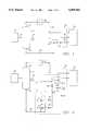
- FIG. 1is a schematic diagram of the present invention; and would be configured to recover petroleum products from a producing well utilizing a subsea separator and a recirculating liquid line;
- FIG. 2is a schematic diagram of an alternative embodiment of the invention wherein eductors introduce recovered liquid hydrocarbon into a liquid flowline;
- FIG. 3is a schematic diagram of an alternative embodiment of the invention wherein hydraulic pumps introduce recovered liquid hydrocarbon into a liquid flowline;
- FIG. 4is a schematic of an alternative embodiment wherein an electric pump is used to introduce recovered liquid hydrocarbon into a circulating liquid flowline through a manifold.
- the present inventionis shown in relation to a conventional subsea wellhead 10.
- a composite hydrocarbon streamis produced through wellhead 10 from a subsea well.
- Wellhead 10is connected by a relatively short segment of pipe 12 to separator 14.
- Pipe 12is of a suitable length and diameter to span the distance between separator 14 and wellhead 10 without producing excessive backpressure on the well. Normally, this distance is between 10 and 50 feet, although longer distances are sometimes encountered.
- Pipe 12is joined to separator 14 and the wellhead 10 in such a way as to maintain a liquid seal under the temperatures and pressures typically associated with wells, a characteristic common to all connections in the present system.
- Such flowline connectionscan be made by methods that are well known in the subsea liquid hydrocarbon production art.
- separatorscan be used to accomplish the separation contemplated in the present invention.
- basic separator designis explained in SURFACE PRODUCTION OPERATIONS, Volume I, Design of Oil and Water Handling Systems, co-authored by the inventor.
- Various centrifugal type separatorscould also be employed, such as that explained in "A Simple Model for the Efficiency of Rotary Separators” by Alhanati, J. S., et al. (SPE 1994), “Evaluation of the Performance of a New Upflow Design, by Aretz, H. J., 1993, published in SPE INTERNATIONAL, "New Separator Cuts Motion Effects on Floating Facilities” OCEAN INDUSTRY, June 1992, and the separator described in the aforementioned U.S. Pat. No. 4,705,114.
- the composite hydrocarbon streamis separated into a vapor hydrocarbon stream and a liquid hydrocarbon stream in separator 14.
- the separator 14is connected to a vapor flowline 20 at an exit port 16.
- flowline 20is not insulated to prevent loss of heat to the surrounding sea water.
- the hydrocarbon vapor streamexits separator 14 through exit port 16 and flows to the surface through vapor flowline 20, from which it is collected for downstream processing.
- vapor flowline 20leads to a platform 32, which is above the sea level. In this embodiment, vapor is collected for downstream processing on platform 32 by standard means.
- the separated liquid hydrocarbon streamexits separator 14 through an exit port 18 and flows through a pipe 22.
- pipe 22is operably connected to an introducing means 24 for introducing the recovered liquid hydrocarbon stream into a liquid flowline 28.
- recycle line 26, introducing means 24 and liquid flowline 28form a circulating loop 29.
- Recycle flowline 26extends between platform 32 and introducing means 24. Recycle liquid is pumped into recycle flowline 26 from platform 32. Recycle liquid passes through introducing means 24, where it is joined by the recovered liquid hydrocarbon stream. The mixed liquid flows from introducing means 24 through liquid flowline 28, from which it is collected for later processing. In the preferred embodiment, liquid flowline 28 returns the mixed liquid to platform 32.
- Platform 32is suitably equipped to separate recovered hydrocarbon from produced water and is capable of storing or down stream processing the recovered hydrocarbons and water.
- Platform 32is configured to introduce water, liquid hydrocarbon or selected mixtures of water and liquid hydrocarbon into recycle line 26 to maintain sufficient flowrates in liquid flowline 28 and a high enough water cut so that paraffin deposition can be eliminated or minimized for easy pigging.
- Pigscan be launched from platform 32 through recycle line 26 and liquid flowline 28, and be recovered on platform 32. It is also possible to provide valves so that pigs launched from platform 32 can be routed through gas flowline 20.
- the liquid in the return flowlineis maintained between 20 to 60 percent water. At this ratio, flow in the liquid flowline 28 can be completely shutdown and any paraffins that form will have a low shear strength, facilitating restarts after shutdown.
- flowlines 28, 20 and 26can be bundled, as shown in phantom at 30, so that the bundled flowlines are in thermal contact. They can be bundled along part or all of their length as desired.
- Hot liquid in one flowlineprovides heat to cooler flowlines in this configuration.
- platform 32is equipped with a means to heat the recycle fluid before pumping it into recycle line 26. Platform 32 is equipped to monitor the temperature of the liquid hydrocarbon stream as it exits liquid flowline 28. This temperature is maintained above the cloud point by heating recycle liquid introduced into the recycle line 26 or by increasing the flow in recycle line 26.
- introducing device 24is an eductor system 25 controlled by level sensor 34.
- the eductor systemcan consist of one or more eductors operating in parallel.
- recycle liquidpasses through at least one eductor 51, creating an area of low pressure which allows flow from pipe 22 to enter the eductor and flow into pipe 28, even though the pressure in pipe 22 is lower than the pressure in pipe 28.
- the level sensor 34directs liquid from recycle line 26 into eductors 51 by opening and closing valves 52. Pressure sensors 53 on recycle line 26 send a signal to valve 54 to allow excess liquid to be discharged to the sea through line 55 (if the liquid in recycle line 26 meets applicable environmental criteria), or injected into wells for waterflood purposes through line 55.
- introducing device 24can be an hydraulic pump system 40 as shown in FIG. 3, with one or more hydraulic pumps 41, or an electric motor pump system 42 as shown in FIG. 4, with one or more electric pumps 43.
- level sensor 34can control starting or stopping of the pumps and/or flow throttle control valve 57.
- the backpressure on the separatoris determined by the sum of the gas pressure drop in pipe 20, the outlet pressure of pipe 20 on platform 32 and the pressure required to overcome the weight of the column of gas in pipe 20. If lower pressures are required, a compressor could be installed at 35 in pipe 20.
- the systemmay be configured to allow recycle liquid to circulate through the gas flowline to facilitate recirculation, to allow pigging the gas flowline in the event that the gas flowline becomes partially blocked, or the recycle flowline also can be used to inject liquid back into the well to keep the well bore, wellhead and separator warm in case of extended shut-in. All such modifications are intended to be included within the scope of the appended claims.
Landscapes
- Life Sciences & Earth Sciences (AREA)
- Engineering & Computer Science (AREA)
- Geology (AREA)
- Mining & Mineral Resources (AREA)
- Physics & Mathematics (AREA)
- Environmental & Geological Engineering (AREA)
- Fluid Mechanics (AREA)
- General Life Sciences & Earth Sciences (AREA)
- Geochemistry & Mineralogy (AREA)
- Chemical & Material Sciences (AREA)
- Chemical Kinetics & Catalysis (AREA)
- Production Of Liquid Hydrocarbon Mixture For Refining Petroleum (AREA)
Abstract
Description
Claims (13)
Priority Applications (2)
| Application Number | Priority Date | Filing Date | Title |
|---|---|---|---|
| US08/384,924US5490562A (en) | 1995-02-07 | 1995-02-07 | Subsea flow enhancer |
| PCT/US1995/012440WO1996024750A1 (en) | 1995-02-07 | 1995-09-27 | Subsea flow enhancer |
Applications Claiming Priority (1)
| Application Number | Priority Date | Filing Date | Title |
|---|---|---|---|
| US08/384,924US5490562A (en) | 1995-02-07 | 1995-02-07 | Subsea flow enhancer |
Publications (1)
| Publication Number | Publication Date |
|---|---|
| US5490562Atrue US5490562A (en) | 1996-02-13 |
Family
ID=23519313
Family Applications (1)
| Application Number | Title | Priority Date | Filing Date |
|---|---|---|---|
| US08/384,924Expired - Fee RelatedUS5490562A (en) | 1995-02-07 | 1995-02-07 | Subsea flow enhancer |
Country Status (2)
| Country | Link |
|---|---|
| US (1) | US5490562A (en) |
| WO (1) | WO1996024750A1 (en) |
Cited By (36)
| Publication number | Priority date | Publication date | Assignee | Title |
|---|---|---|---|---|
| WO1999043924A1 (en)* | 1998-02-24 | 1999-09-02 | Multiphase Power And Processing Technologies Llc | Energy recovery in a wellbore |
| US5983822A (en) | 1998-09-03 | 1999-11-16 | Texaco Inc. | Polygon floating offshore structure |
| US6142707A (en)* | 1996-03-26 | 2000-11-07 | Shell Oil Company | Direct electric pipeline heating |
| US6171025B1 (en)* | 1995-12-29 | 2001-01-09 | Shell Oil Company | Method for pipeline leak detection |
| US6179523B1 (en) | 1995-12-29 | 2001-01-30 | Shell Oil Company | Method for pipeline installation |
| US6197095B1 (en)* | 1999-02-16 | 2001-03-06 | John C. Ditria | Subsea multiphase fluid separating system and method |
| US6230645B1 (en) | 1998-09-03 | 2001-05-15 | Texaco Inc. | Floating offshore structure containing apertures |
| US6264401B1 (en) | 1995-12-29 | 2001-07-24 | Shell Oil Company | Method for enhancing the flow of heavy crudes through subsea pipelines |
| US6315497B1 (en)* | 1995-12-29 | 2001-11-13 | Shell Oil Company | Joint for applying current across a pipe-in-pipe system |
| WO2001073261A3 (en)* | 2000-03-27 | 2002-02-28 | Rockwater Ltd | Riser with retrievable internal services |
| US6367547B1 (en) | 1999-04-16 | 2002-04-09 | Halliburton Energy Services, Inc. | Downhole separator for use in a subterranean well and method |
| US6686745B2 (en) | 2001-07-20 | 2004-02-03 | Shell Oil Company | Apparatus and method for electrical testing of electrically heated pipe-in-pipe pipeline |
| US6688900B2 (en) | 2002-06-25 | 2004-02-10 | Shell Oil Company | Insulating joint for electrically heated pipeline |
| US6714018B2 (en) | 2001-07-20 | 2004-03-30 | Shell Oil Company | Method of commissioning and operating an electrically heated pipe-in-pipe subsea pipeline |
| US20040060693A1 (en)* | 2001-07-20 | 2004-04-01 | Bass Ronald Marshall | Annulus for electrically heated pipe-in-pipe subsea pipeline |
| US6739803B2 (en) | 2001-07-20 | 2004-05-25 | Shell Oil Company | Method of installation of electrically heated pipe-in-pipe subsea pipeline |
| US20040100273A1 (en)* | 2002-11-08 | 2004-05-27 | Liney David J. | Testing electrical integrity of electrically heated subsea pipelines |
| US20040159437A1 (en)* | 2003-02-13 | 2004-08-19 | Conocophillips, Company | Sub-sea blow case compressor |
| US20090050326A1 (en)* | 2005-07-05 | 2009-02-26 | Aker Kvaerner Subsea As | Device and Method for Cleaning a Compressor |
| WO2009042307A1 (en)* | 2007-09-25 | 2009-04-02 | Exxonmobile Upstream Research Company | Method and apparatus for flow assurance management in subsea single production flowline |
| US20100032164A1 (en)* | 2006-10-27 | 2010-02-11 | William Bakke | Sub sea processing system |
| US20100193194A1 (en)* | 2007-09-25 | 2010-08-05 | Stoisits Richard F | Method For Managing Hydrates In Subsea Production Line |
| US20100284829A1 (en)* | 2009-05-06 | 2010-11-11 | Curtiss-Wright Electro-Mechanical Corporation | Gas tolerant subsea pump |
| US20110067881A1 (en)* | 2008-12-16 | 2011-03-24 | Chevron U.S.A. Inc. | System and method for delivering material to a subsea well |
| US20110158824A1 (en)* | 2009-12-24 | 2011-06-30 | Wright David C | Subsea technique for promoting fluid flow |
| US20110171817A1 (en)* | 2010-01-12 | 2011-07-14 | Axcelis Technologies, Inc. | Aromatic Molecular Carbon Implantation Processes |
| FR2961551A1 (en)* | 2010-06-21 | 2011-12-23 | Total Sa | Preparing hydrocarbons comprises extracting fluid in subterranean formation, separating fluid in liquid and gaseous phases, injecting compound inhibiting formation of hydrates, transporting liquid and gaseous phases in pipe and recovering |
| US20120073822A1 (en)* | 2008-04-04 | 2012-03-29 | Vws Westgarth Limited | Fluid Treatment System |
| US20120257990A1 (en)* | 2009-12-29 | 2012-10-11 | Erikson Klas Goeran | Control of subsea compressors |
| US20150291901A1 (en)* | 2012-11-26 | 2015-10-15 | Statoil Petroleum As | Combined dehydration of gas and inhibition of liquid from a well stream |
| US9879663B2 (en)* | 2013-03-01 | 2018-01-30 | Advanced Cooling Technologies, Inc. | Multi-phase pump system and method of pumping a two-phase fluid stream |
| US20180200669A1 (en)* | 2011-07-01 | 2018-07-19 | Statoil Petroleum As | Method and system for lowering the water dew point of a hydrocarbon fluid stream subsea |
| US11414962B2 (en) | 2020-09-08 | 2022-08-16 | Frederick William MacDougall | Coalification and carbon sequestration using deep ocean hydrothermal borehole vents |
| US11448055B2 (en) | 2019-05-16 | 2022-09-20 | David C. Wright | Subsea duplex pump, subsea pumping system, and subsea pumping method |
| US11794893B2 (en) | 2020-09-08 | 2023-10-24 | Frederick William MacDougall | Transportation system for transporting organic payloads |
| WO2024042351A1 (en)* | 2022-08-25 | 2024-02-29 | Al Ajaji Abdulaziz | Zero flaring operations using non-metallic pipes |
Citations (8)
| Publication number | Priority date | Publication date | Assignee | Title |
|---|---|---|---|---|
| US4284139A (en)* | 1980-02-28 | 1981-08-18 | Conoco, Inc. | Process for stimulating and upgrading the oil production from a heavy oil reservoir |
| US4480691A (en)* | 1982-09-29 | 1984-11-06 | Herter George L | Recycled fatty acid crude petroleum recovery process |
| US4664190A (en)* | 1985-12-18 | 1987-05-12 | Shell Western E&P Inc. | Process for recovering natural gas liquids |
| US4741398A (en)* | 1986-12-30 | 1988-05-03 | The United States Of America As Represented By The United States Department Of Energy | Hydraulic accumulator-compressor for geopressured enhanced oil recovery |
| US5109928A (en)* | 1990-08-17 | 1992-05-05 | Mccants Malcolm T | Method for production of hydrocarbon diluent from heavy crude oil |
| US5149344A (en)* | 1991-05-02 | 1992-09-22 | Texaco Inc. | Multi-phase flow and separator |
| US5236605A (en)* | 1992-07-07 | 1993-08-17 | Horizontal Rentals, Inc. | Method and apparatus for continuous separation of oil from solid and liquid contaminants |
| US5390740A (en)* | 1993-12-17 | 1995-02-21 | Texaco Inc. | Method and apparatus to recycle production well casing vapor |
- 1995
- 1995-02-07USUS08/384,924patent/US5490562A/ennot_activeExpired - Fee Related
- 1995-09-27WOPCT/US1995/012440patent/WO1996024750A1/enactiveApplication Filing
Patent Citations (8)
| Publication number | Priority date | Publication date | Assignee | Title |
|---|---|---|---|---|
| US4284139A (en)* | 1980-02-28 | 1981-08-18 | Conoco, Inc. | Process for stimulating and upgrading the oil production from a heavy oil reservoir |
| US4480691A (en)* | 1982-09-29 | 1984-11-06 | Herter George L | Recycled fatty acid crude petroleum recovery process |
| US4664190A (en)* | 1985-12-18 | 1987-05-12 | Shell Western E&P Inc. | Process for recovering natural gas liquids |
| US4741398A (en)* | 1986-12-30 | 1988-05-03 | The United States Of America As Represented By The United States Department Of Energy | Hydraulic accumulator-compressor for geopressured enhanced oil recovery |
| US5109928A (en)* | 1990-08-17 | 1992-05-05 | Mccants Malcolm T | Method for production of hydrocarbon diluent from heavy crude oil |
| US5149344A (en)* | 1991-05-02 | 1992-09-22 | Texaco Inc. | Multi-phase flow and separator |
| US5236605A (en)* | 1992-07-07 | 1993-08-17 | Horizontal Rentals, Inc. | Method and apparatus for continuous separation of oil from solid and liquid contaminants |
| US5390740A (en)* | 1993-12-17 | 1995-02-21 | Texaco Inc. | Method and apparatus to recycle production well casing vapor |
Cited By (58)
| Publication number | Priority date | Publication date | Assignee | Title |
|---|---|---|---|---|
| US6171025B1 (en)* | 1995-12-29 | 2001-01-09 | Shell Oil Company | Method for pipeline leak detection |
| US6179523B1 (en) | 1995-12-29 | 2001-01-30 | Shell Oil Company | Method for pipeline installation |
| US6264401B1 (en) | 1995-12-29 | 2001-07-24 | Shell Oil Company | Method for enhancing the flow of heavy crudes through subsea pipelines |
| US6315497B1 (en)* | 1995-12-29 | 2001-11-13 | Shell Oil Company | Joint for applying current across a pipe-in-pipe system |
| US6142707A (en)* | 1996-03-26 | 2000-11-07 | Shell Oil Company | Direct electric pipeline heating |
| WO1999043924A1 (en)* | 1998-02-24 | 1999-09-02 | Multiphase Power And Processing Technologies Llc | Energy recovery in a wellbore |
| US6383262B1 (en)* | 1998-02-24 | 2002-05-07 | Multiphase Power And Processing Technologies, Inc. | Energy recovery in a wellbore |
| US5983822A (en) | 1998-09-03 | 1999-11-16 | Texaco Inc. | Polygon floating offshore structure |
| US6230645B1 (en) | 1998-09-03 | 2001-05-15 | Texaco Inc. | Floating offshore structure containing apertures |
| US6197095B1 (en)* | 1999-02-16 | 2001-03-06 | John C. Ditria | Subsea multiphase fluid separating system and method |
| US6367547B1 (en) | 1999-04-16 | 2002-04-09 | Halliburton Energy Services, Inc. | Downhole separator for use in a subterranean well and method |
| WO2001073261A3 (en)* | 2000-03-27 | 2002-02-28 | Rockwater Ltd | Riser with retrievable internal services |
| US6739803B2 (en) | 2001-07-20 | 2004-05-25 | Shell Oil Company | Method of installation of electrically heated pipe-in-pipe subsea pipeline |
| US6686745B2 (en) | 2001-07-20 | 2004-02-03 | Shell Oil Company | Apparatus and method for electrical testing of electrically heated pipe-in-pipe pipeline |
| US6714018B2 (en) | 2001-07-20 | 2004-03-30 | Shell Oil Company | Method of commissioning and operating an electrically heated pipe-in-pipe subsea pipeline |
| US20040060693A1 (en)* | 2001-07-20 | 2004-04-01 | Bass Ronald Marshall | Annulus for electrically heated pipe-in-pipe subsea pipeline |
| US6814146B2 (en) | 2001-07-20 | 2004-11-09 | Shell Oil Company | Annulus for electrically heated pipe-in-pipe subsea pipeline |
| US6688900B2 (en) | 2002-06-25 | 2004-02-10 | Shell Oil Company | Insulating joint for electrically heated pipeline |
| US20040100273A1 (en)* | 2002-11-08 | 2004-05-27 | Liney David J. | Testing electrical integrity of electrically heated subsea pipelines |
| US6937030B2 (en) | 2002-11-08 | 2005-08-30 | Shell Oil Company | Testing electrical integrity of electrically heated subsea pipelines |
| US20040159437A1 (en)* | 2003-02-13 | 2004-08-19 | Conocophillips, Company | Sub-sea blow case compressor |
| US6907933B2 (en)* | 2003-02-13 | 2005-06-21 | Conocophillips Company | Sub-sea blow case compressor |
| US20090050326A1 (en)* | 2005-07-05 | 2009-02-26 | Aker Kvaerner Subsea As | Device and Method for Cleaning a Compressor |
| US9435186B2 (en)* | 2006-10-27 | 2016-09-06 | Statoil Petroleum As | Sub sea processing system |
| US20100032164A1 (en)* | 2006-10-27 | 2010-02-11 | William Bakke | Sub sea processing system |
| US8919445B2 (en)* | 2007-02-21 | 2014-12-30 | Exxonmobil Upstream Research Company | Method and system for flow assurance management in subsea single production flowline |
| US20120031621A1 (en)* | 2007-02-21 | 2012-02-09 | Fowler Tracy A | Method and System For Flow Assurance Management In Subsea Single Production Flowline |
| US20100193194A1 (en)* | 2007-09-25 | 2010-08-05 | Stoisits Richard F | Method For Managing Hydrates In Subsea Production Line |
| US20100252260A1 (en)* | 2007-09-25 | 2010-10-07 | Fowler Tracy A | Method and Apparatus For Flow Assurance Management In Subsea Single Production Flowline |
| WO2009042307A1 (en)* | 2007-09-25 | 2009-04-02 | Exxonmobile Upstream Research Company | Method and apparatus for flow assurance management in subsea single production flowline |
| US8430169B2 (en) | 2007-09-25 | 2013-04-30 | Exxonmobil Upstream Research Company | Method for managing hydrates in subsea production line |
| US8469101B2 (en)* | 2007-09-25 | 2013-06-25 | Exxonmobil Upstream Research Company | Method and apparatus for flow assurance management in subsea single production flowline |
| US9010438B2 (en)* | 2008-04-04 | 2015-04-21 | Vws Westgarth Limited | Fluid treatment system |
| US20120073822A1 (en)* | 2008-04-04 | 2012-03-29 | Vws Westgarth Limited | Fluid Treatment System |
| US20110067881A1 (en)* | 2008-12-16 | 2011-03-24 | Chevron U.S.A. Inc. | System and method for delivering material to a subsea well |
| US20100284829A1 (en)* | 2009-05-06 | 2010-11-11 | Curtiss-Wright Electro-Mechanical Corporation | Gas tolerant subsea pump |
| WO2010129749A1 (en)* | 2009-05-06 | 2010-11-11 | Curtiss-Wright Electro-Mechanical Corporation | Gas tolerant subsea pump |
| US8393876B2 (en) | 2009-05-06 | 2013-03-12 | Curtiss-Wright Electro-Mechanical Corp. | Gas tolerant subsea pump |
| US20110158824A1 (en)* | 2009-12-24 | 2011-06-30 | Wright David C | Subsea technique for promoting fluid flow |
| US9435185B2 (en) | 2009-12-24 | 2016-09-06 | Wright's Well Control Services, Llc | Subsea technique for promoting fluid flow |
| US10161238B2 (en)* | 2009-12-24 | 2018-12-25 | Wright's Well Control Services, Llc | Subsea technique for promoting fluid flow |
| US20120257990A1 (en)* | 2009-12-29 | 2012-10-11 | Erikson Klas Goeran | Control of subsea compressors |
| US9382921B2 (en)* | 2009-12-29 | 2016-07-05 | Aker Subsea As | Control of subsea compressors |
| US20110171817A1 (en)* | 2010-01-12 | 2011-07-14 | Axcelis Technologies, Inc. | Aromatic Molecular Carbon Implantation Processes |
| FR2961551A1 (en)* | 2010-06-21 | 2011-12-23 | Total Sa | Preparing hydrocarbons comprises extracting fluid in subterranean formation, separating fluid in liquid and gaseous phases, injecting compound inhibiting formation of hydrates, transporting liquid and gaseous phases in pipe and recovering |
| US20180200669A1 (en)* | 2011-07-01 | 2018-07-19 | Statoil Petroleum As | Method and system for lowering the water dew point of a hydrocarbon fluid stream subsea |
| US10786780B2 (en)* | 2011-07-01 | 2020-09-29 | Equinor Energy As | Method and system for lowering the water dew point of a hydrocarbon fluid stream subsea |
| US20180187112A1 (en)* | 2012-11-26 | 2018-07-05 | Statoil Petroleum As | Combined dehydration of gas and inhibition of liquid from a well stream |
| US10184090B2 (en)* | 2012-11-26 | 2019-01-22 | Statoil Petroleum As | Combined dehydration of gas and inhibition of liquid from a well stream |
| US20190093039A1 (en)* | 2012-11-26 | 2019-03-28 | Statoil Petroleum As | Combined dehydration of gas and inhibition of liquid from a well stream |
| US10576415B2 (en)* | 2012-11-26 | 2020-03-03 | Equinor Energy As | Combined dehydration of gas and inhibition of liquid from a well stream |
| US20150291901A1 (en)* | 2012-11-26 | 2015-10-15 | Statoil Petroleum As | Combined dehydration of gas and inhibition of liquid from a well stream |
| US10821398B2 (en)* | 2012-11-26 | 2020-11-03 | Equinor Energy As | Combined dehydration of gas and inhibition of liquid from a well stream |
| US9879663B2 (en)* | 2013-03-01 | 2018-01-30 | Advanced Cooling Technologies, Inc. | Multi-phase pump system and method of pumping a two-phase fluid stream |
| US11448055B2 (en) | 2019-05-16 | 2022-09-20 | David C. Wright | Subsea duplex pump, subsea pumping system, and subsea pumping method |
| US11414962B2 (en) | 2020-09-08 | 2022-08-16 | Frederick William MacDougall | Coalification and carbon sequestration using deep ocean hydrothermal borehole vents |
| US11794893B2 (en) | 2020-09-08 | 2023-10-24 | Frederick William MacDougall | Transportation system for transporting organic payloads |
| WO2024042351A1 (en)* | 2022-08-25 | 2024-02-29 | Al Ajaji Abdulaziz | Zero flaring operations using non-metallic pipes |
Also Published As
| Publication number | Publication date |
|---|---|
| WO1996024750A1 (en) | 1996-08-15 |
Similar Documents
| Publication | Publication Date | Title |
|---|---|---|
| US5490562A (en) | Subsea flow enhancer | |
| US8430169B2 (en) | Method for managing hydrates in subsea production line | |
| US8919445B2 (en) | Method and system for flow assurance management in subsea single production flowline | |
| US7152682B2 (en) | Subsea process assembly | |
| AU2009202054B2 (en) | Subsea Compression System and Method | |
| US6772840B2 (en) | Methods and apparatus for a subsea tie back | |
| US8857519B2 (en) | Method of retrofitting subsea equipment with separation and boosting | |
| US20030145991A1 (en) | Subsea production system | |
| EA012681B1 (en) | Apparatus for extracting, cooling and transporting effluents produced by an undersea well (embodiments) | |
| US20120073823A1 (en) | System for subsea extraction of gaseous materials from, and prevention, of hydrates | |
| WO2006031335A1 (en) | Method for managing hydrates in subsea production line | |
| US9004177B2 (en) | Subsea production systems and methods | |
| US7243721B2 (en) | Methods and apparatus for heating oil production reservoirs | |
| US20250101846A1 (en) | Downhole fluid and solid separation with sediment and nonproduction fluid management in a well | |
| WO2015036041A1 (en) | Hydrocarbon separation apparatus with recirculation loop | |
| Marjohan | How to Increase Recovery of Hydrocarbons Utilizing Subsea Processing Technology | |
| WO2008035090A1 (en) | Method of inhibiting hydrate formation | |
| Scott et al. | Assessment of subsea production & well systems | |
| Mandke et al. | Single trip pigging of gas lines during late field life | |
| Birkeland et al. | An Efficient Wellstream Booster Solution for Deep and Ultra Deep Water Oil Fields | |
| WO2020246899A1 (en) | Controlling the temperature of injection water for reservoir pressure support | |
| Beran et al. | Subsea Pressure Boost/Separation: A Necessity for Deepwater Development? | |
| GB2371817A (en) | Method of providing artificial lift in a well |
Legal Events
| Date | Code | Title | Description |
|---|---|---|---|
| AS | Assignment | Owner name:PARAGON ENGINEERING SERVICES INCORPORATED, TEXAS Free format text:ASSIGNMENT OF ASSIGNORS INTEREST;ASSIGNOR:ARNOLD, KENNETH E.;REEL/FRAME:007359/0334 Effective date:19950206 | |
| FEPP | Fee payment procedure | Free format text:PAYOR NUMBER ASSIGNED (ORIGINAL EVENT CODE: ASPN); ENTITY STATUS OF PATENT OWNER: SMALL ENTITY | |
| FPAY | Fee payment | Year of fee payment:4 | |
| AS | Assignment | Owner name:CHASE MANHATTAN BANK, AS COLLATERAL AGENT, THE, NE Free format text:SECURITY INTEREST;ASSIGNOR:MASCOTECH, INC.;REEL/FRAME:011457/0321 Effective date:20001128 | |
| AS | Assignment | Owner name:METALDYNE CORPORATION (F/K/A MASCOTECH, INC.), MIC Free format text:RELEASE;ASSIGNOR:JPMORGAN CHASE BANK (F/K/A THE CHASE MANHATTAN BANK) AS COLLATERAL AGENT;REEL/FRAME:013169/0624 Effective date:20020808 | |
| REMI | Maintenance fee reminder mailed | ||
| LAPS | Lapse for failure to pay maintenance fees | ||
| FP | Lapsed due to failure to pay maintenance fee | Effective date:20040213 | |
| AS | Assignment | Owner name:MASCOTECH, INC., MICHIGAN Free format text:TERMINATION AND RELEASE OF SECURITY INTEREST IN PATENT RIGHTS;ASSIGNOR:JPMORGAN CHASE BANK, N.A. (F/K/A THE CHASE MANHATTAN BANK), AS COLLATERAL AGENT;REEL/FRAME:018861/0449 Effective date:20070111 | |
| STCH | Information on status: patent discontinuation | Free format text:PATENT EXPIRED DUE TO NONPAYMENT OF MAINTENANCE FEES UNDER 37 CFR 1.362 |