US5490533A - Collapsible shelter with elevated canopy - Google Patents
Collapsible shelter with elevated canopyDownload PDFInfo
- Publication number
- US5490533A US5490533AUS08/042,996US4299693AUS5490533AUS 5490533 AUS5490533 AUS 5490533AUS 4299693 AUS4299693 AUS 4299693AUS 5490533 AUS5490533 AUS 5490533A
- Authority
- US
- United States
- Prior art keywords
- link
- central
- truss
- pairs
- truss pairs
- Prior art date
- Legal status (The legal status is an assumption and is not a legal conclusion. Google has not performed a legal analysis and makes no representation as to the accuracy of the status listed.)
- Expired - Lifetime
Links
- 239000004744fabricSubstances0.000description3
- 238000001556precipitationMethods0.000description3
- 239000004677NylonSubstances0.000description1
- 208000018747cerebellar ataxia with neuropathy and bilateral vestibular areflexia syndromeDiseases0.000description1
- 239000003562lightweight materialSubstances0.000description1
- 239000000463materialSubstances0.000description1
- 230000004048modificationEffects0.000description1
- 238000012986modificationMethods0.000description1
- 229920001778nylonPolymers0.000description1
- 239000004033plasticSubstances0.000description1
Images


Classifications
- E—FIXED CONSTRUCTIONS
- E04—BUILDING
- E04H—BUILDINGS OR LIKE STRUCTURES FOR PARTICULAR PURPOSES; SWIMMING OR SPLASH BATHS OR POOLS; MASTS; FENCING; TENTS OR CANOPIES, IN GENERAL
- E04H15/00—Tents or canopies, in general
- E04H15/32—Parts, components, construction details, accessories, interior equipment, specially adapted for tents, e.g. guy-line equipment, skirts, thresholds
- E04H15/58—Closures; Awnings; Sunshades
- E—FIXED CONSTRUCTIONS
- E04—BUILDING
- E04H—BUILDINGS OR LIKE STRUCTURES FOR PARTICULAR PURPOSES; SWIMMING OR SPLASH BATHS OR POOLS; MASTS; FENCING; TENTS OR CANOPIES, IN GENERAL
- E04H15/00—Tents or canopies, in general
- E04H15/32—Parts, components, construction details, accessories, interior equipment, specially adapted for tents, e.g. guy-line equipment, skirts, thresholds
- E04H15/34—Supporting means, e.g. frames
- E04H15/44—Supporting means, e.g. frames collapsible, e.g. breakdown type
- E04H15/46—Supporting means, e.g. frames collapsible, e.g. breakdown type telescoping and foldable
- E—FIXED CONSTRUCTIONS
- E04—BUILDING
- E04H—BUILDINGS OR LIKE STRUCTURES FOR PARTICULAR PURPOSES; SWIMMING OR SPLASH BATHS OR POOLS; MASTS; FENCING; TENTS OR CANOPIES, IN GENERAL
- E04H15/00—Tents or canopies, in general
- E04H15/32—Parts, components, construction details, accessories, interior equipment, specially adapted for tents, e.g. guy-line equipment, skirts, thresholds
- E04H15/34—Supporting means, e.g. frames
- E04H15/44—Supporting means, e.g. frames collapsible, e.g. breakdown type
- E04H15/48—Supporting means, e.g. frames collapsible, e.g. breakdown type foldable, i.e. having pivoted or hinged means
- E04H15/50—Supporting means, e.g. frames collapsible, e.g. breakdown type foldable, i.e. having pivoted or hinged means lazy-tongs type
- E—FIXED CONSTRUCTIONS
- E04—BUILDING
- E04H—BUILDINGS OR LIKE STRUCTURES FOR PARTICULAR PURPOSES; SWIMMING OR SPLASH BATHS OR POOLS; MASTS; FENCING; TENTS OR CANOPIES, IN GENERAL
- E04H15/00—Tents or canopies, in general
- E04H15/32—Parts, components, construction details, accessories, interior equipment, specially adapted for tents, e.g. guy-line equipment, skirts, thresholds
- E04H15/60—Poles
Definitions
- This inventionrelates generally to folding, collapsible structures, and more particularly relates to a collapsible, field shelter structure having an elevated canopy.
- Temporary shelters that can be easily transported and rapidly set up at emergency sitescan be particularly useful in providing temporary care and housing. Such shelters can also be useful for non-emergency outdoor gatherings, such as for temporary military posts, field trips, and the like.
- One such quickly erectable, collapsible shelter having a framework of X-shaped linkages, telescoping legs, and a canopy covering the frameworkis described in my U.S. Pat. No. 4,607,656.
- the legs of that shelterare capable of telescoping to about twice their stowed length, and the framework of X-shaped truss pairs is capable of horizontal extension between the legs to support a canopy.
- the frameworkcan be constructed of lightweight material, and the telescoping legs can be extended to raise the framework of the shelter.
- the height of the canopyis limited to the extended length of the legs, and the canopy is essentially flat, allowing for collection of precipitation and debris on top of the canopy, which can promote leaks and tears in the canopy.
- the size and stability of the shelteris generally limited by the strength of the framework.
- the present inventionprovides for a collapsible shelter with an improved truss framework that raises a gabled shelter canopy to provide increased headroom, strength and stability.
- the inventionaccordingly provides for a collapsible shelter having a canopy with at least three vertically disposed legs supporting the canopy. At least one perimeter truss means is connected to each of the legs.
- Each of the perimeter truss meanspreferably includes a pair of first and second link members, with the first link member having an outer end connected to the upper end of one leg, and the second link member having an outer end slidably connected to the leg.
- the first and second link membersare pivotally connected together in a scissors configuration so as to be extendable from a first collapsed position extending horizontally between two legs to a second extended position extending above the legs.
- the perimiter truss meansincludes a second perimeter truss pair of link members connected to each of the first perimeter truss pairs, with the first link of the second perimeter truss pairs being pivotally connected to the second link of a corresponding first perimeter truss pair, and the second link of the second perimeter truss pair being pivotally connected to the first link of the corresponding first perimeter truss pair.
- the first and second link members of the second perimeter truss pairsare also preferably pivotally connected together in a modified scissors configuration so as to be extendable from a first collapsed position extending horizontally between legs to a second extended position extending above the first perimeter truss pair.
- At least two central truss meansare also provided, with each of the central truss means including a pair of first and second link members connected together in a scissors configuration.
- Each of the central truss pairsare connected to the inner ends of one perimeter truss means, and the first and second link members are pivotally connected together in a scissors configuration so as to be extendable from a first collapsed position to a second extended position.
- tensioning meansare also secured between the leg slider member and the central support slider member, to provide additional strength and stability to the framework of the shelter in a raised, extended configuration.
- first perimeter truss pairs of link membersare connected to each of four legs.
- the outer end of the first link of each truss pair connected to the legis pivotally connected to the upper end of a leg, and the outer end of the second link is slidably connected to the leg, preferably being pivotally secured to a slider member on the leg.
- the first and second link membersare pivotally connected together in a modified scissors configuration so as to be extendable from a first collapsed position extending horizontally between adjacent legs to a second extended position extending above the legs.
- Second perimeter truss pairs of link membersare also preferably connected to each of the first perimeter truss pairs, with the first link of the second perimeter truss pairs being pivotally connected to the second link of a corresponding first perimeter truss pair, and the second link of the second perimeter truss pair being pivotally connected to the first link of the corresponding first perimeter truss pair.
- the first and second link members of the second perimeter truss pairsare also preferably pivotally connected together in a modified scissors configuration so as to be extendable from a first collapsed position extending horizontally between legs to a second extended position extending above the first perimeter truss pair.
- Each of the second perimeter truss pairsare preferably pivotally connected to another second perimeter truss pair.
- At least two first central truss pairs of link membersare also provided in the four-sided shelter embodiment, pivotally connected together in a scissors configuration are each connected to the inner ends of one of the perimeter truss pairs, and are preferably pivotally connected to a junction of the inner ends of second perimeter truss pairs.
- At least two second, inner central truss pairs of link members pivotally connected together in a scissors configurationare preferably each pivotally connected to the inner ends of one of the first, outer central truss pairs.
- the inner ends of the central truss pairsare preferably pivotally connected to the inner ends of at least one other of the inner central truss pairs, and are preferably pivotally connected to a vertically oriented central support member supporting the canopy and a central support slider member disposed to slidably engage the central support member.
- Tensioning meansare also preferably provided between the leg slider member and the central support slider member.
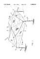
- FIG. 1is a perspective view of the improved collapsible shelter with an elevated canopy of the invention, showing the elevated gabled roof structure;
- FIG. 2is a cross-sectional elevational view of the collapsible shelter of the invention, taken along line 2--2 of FIG. 1, showing the perimeter and central truss pairs of the shelter in an extended, raised configuration;
- FIG. 3is a top sectional view of the collapsible shelter of the invention.
- FIG. 4is an enlarged view of a portion of the linkage between the perimeter truss pairs and the central truss pairs;
- FIG. 5is an enlarged sectional view of a leg of the collapsible shelter, taken along line 5--5 of FIG. 3;
- FIG. 6is a side elevational view of the framework of the collapsible shelter, showing the perimeter truss pairs in a substantially collapsed configuration
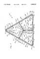
- FIG. 7is a top sectional view of a three-sided embodiment of the collapsible shelter of the invention, similar to that shown in FIG. 3.
- the size and available headroom of previous collapsible sheltershave been generally limited by the extended length of the legs of the structure, and provided essentially flat roof structures, allowing for collection of precipitation in pockets or puddles on top of the shelter.
- the improved collapsible shelter of the inventionprovides for larger, lighter collapsible shelter structures, with a raised gabled roof structure which also improves the strength and stability of the shelter.
- the inventionis embodied in an improved collapsible shelter 10, having a canopy 12 with at least three sides 14, and preferably four sides, at least three corners 16, and preferably four corners.
- the canopyis preferably formed of nylon fabric, so as to be light and easily transportable, although the canopy could also be made of other suitable sheet materials, such as canvass, or other types of cloth fabric, or plastic.
- each of the legshas an upper end 20 and a lower end 22, and preferably each leg includes telescoping upper and lower sections 24 and 26, respectively, with the telescoping lower section including a spring loaded detent pin 27 for indexing in apertures 28 provided in the upper section for adjusting the leg height as desired.
- the extendable lower sectionalso preferably includes a foot portion 29 for engagement with the ground or other floor surface.
- a leg slider member 32is also slidably mounted on the upper section of each of the legs.
- a spring loaded detent pin 34is also provided in the upper leg section for indexing with an aperture 36 in the leg slider member, as will be further explained below.
- the perimeter framework 38includes perimeter truss means 40 including two first perimeter truss pairs 42 of link members connected to each of the legs at right angles, with each of the first perimeter truss pairs including a first link member 44 having an outer end 46 connected to the upper end of a leg, an inner end 48, a longitudinal center 50, and a pivot point 52 spaced apart from the longitudinal center toward the outer end by a predetermined distance L 1 .
- Each of the first perimeter truss pairsfurther includes a second link 54 having an outer end 56 pivotally connected to the leg slider member, thus slidably connecting the second link to the upper section of the leg.
- the second link of the first perimeter truss pairsincludes an inner end 58, a longitudinal center 60, and a pivot point 62 spaced apart from the longitudinal center toward the inner end by the same predetermined distance L 1 .
- the pivot points of the first and second links in each of the first perimeter truss pairsare pivotally connected in a modified scissors configuration, so that although the first and second link members extend a short distance generally horizontally toward another leg in a first collapsed position of the shelter, as shown in FIG. 6, the first and second link members extend to a second extended position with the inner ends of the link members extending above the upper end of the leg, as shown in FIG. 2.
- the perimeter truss meansalso includes a second perimeter truss pair 64 of link members, which is pivotally connected to each of the first perimeter truss pairs, to extend the framework further above the legs of the shelter.
- Each of the second perimeter truss pairspreferably includes a first link 66 having an outer end 68 pivotally connected to the inner end of the second link of the associated first perimeter truss pair, an inner end 70, a longitudinal center point 72, and a pivot point 74 spaced apart from the longitudinal center point toward the inner end a predetermined distance L 2 .
- Each of the second perimeter truss pairsalso preferably includes a second link 76 having an outer end 78 pivotally connected to the inner end of the first link of the associated first perimeter truss pair, an inner end 80, a longitudinal center point 82, and a pivot point 84 spaced apart from the longitudinal center point toward the outer end the predetermined distance L 2 .
- the pivot points of the first and second links in each of the second perimeter truss pairsare preferably pivotally connected together, resulting in a modified scissors configuration so that the second truss pairs are also extendable from a first collapsed position extending generally horizontally between legs, to a second extended position extending above the first perimeter truss pair.
- the inner ends 70 and 80 of each second perimeter truss pairare further preferably pivotally connected to the inner ends 70 and 80 of another second perimeter truss pair at a junction 86 centered between two legs of one side of the shelter framework.
- a plurality of central truss means 88are also provided, including at least two outer central truss pairs 90 of link members, with each of the outer central truss pairs being pivotally connected to the inner ends of at least one of the second perimeter truss pairs at the junction 86, such as by right angle bracket members 87, to which the inner ends of the second perimeter truss pairs and the outer central truss pairs are pivotally connected.
- the framework of the shelterhas a square configuration, and four outer central truss pairs are provided, connected to the four side junctions of the shelter framework. Where the shelter framework has three sides, three outer central truss pairs may be provided.
- Each of the outer central truss pairspreferably includes a first link 92 having an outer end 94 connected to the inner end of the second link of the second perimeter truss pair, an inner end 96, and a pivot point 98 located at the longitudinal center point of the outer central truss pair first link.
- Each of the outer central truss pairsalso preferably includes a second link 100 having an outer end 102 connected to the inner end of the first link of the second perimeter truss pair, an inner end 104, and a pivot point 106 located at the longitudinal center point of the outer central truss pair second link.
- Each of the pivot points of the first and second links of the outer central truss pairsare pivotally connected together to extend horizontally between the sides of the shelter framework.
- the central truss meansalso includes at least two inner central truss pairs 110 of link members, with each of the inner central truss pairs being pivotally connected to the inner ends of an associated outer center truss pair.
- Each of the inner central truss pairspreferably includes a first link 112 having an outer end 114 connected to the inner end of the second link of the outer central truss pair, an inner end 116, and a pivot point 118 located at the longitudinal center point of the inner central truss pair first link.
- Each of the inner central truss pairsalso preferably includes a second link 120 having an outer end 122 connected to the inner end of the first link of the outer central truss pair, an inner end 124, and a pivot point 126 located at the longitudinal center point of the inner central truss pair second link.
- Each of the pivot points of the first and second links of the inner central truss pairsare pivotally connected together to extend horizontally between the sides of the shelter framework.
- the inner ends of each of the first and second links of the inner central truss pairsare preferably pivotally connected to the inner ends of the first and second links of at least one other of the inner central truss pairs.
- the inner ends of the inner central truss pairsare preferably connected to at least one vertically oriented central support member 130 provided to support the canopy when the shelter framework is in an extended configuration.
- a central slider member 132is pivotally connected to an inner end of the inner central truss pair, and is disposed to slidably engage the central support member when the shelter framework is in an extended configuration.
- the inner ends of each of the first links of the inner central truss pairsare preferably pivotally connected to one of the central support member and the central slider member, and the inner ends of each of the second links of the inner central truss pairs are preferably pivotally connected to the other of the central support member and the central slider member.
- a tensioning means 138is preferably connected between the leg slider member and the central support slider member for adding strength and stability to the extended configuration of the shelter framework.
- the tensioning meanspreferably includes a first cable 140 secured to each leg by a bracket 142 on the leg slider, a second cable 144 secured to a bracket 146 on the center slider, and a cable lock 148, such as an over center type of cable lock, for example, securing the first and second cables together.
- the central support membermay also include a peak pole member 150, for further extending the top center of the canopy above the shelter framework, to draw the canopy tight.
- FIG. 7A preferred three-sided embodiment of the collapsible shelter 10' of the invention is illustrated in FIG. 7, in which like reference numerals refer to like elements from the previous figures.
- the three-sided collapsible shelteris substantially similar to the four-sided embodiment illustrated in the previous figures, described above.
- the three-sided shelterincludes a canopy 12' with three sides 14', and three corners 16'.
- Each leg 18'also preferably includes telescoping upper and lower sections for adjusting the leg height as desired, as described previously.
- a leg slider memberis also slidably mounted on the upper section of each of the legs, as described above.
- the perimeter framework 38'includes perimeter truss means 40' including two first perimeter truss pairs 42' of link members connected to each of the legs at approximately 60 degree angles, with each of the first perimeter truss pairs including a first link member 44' having an outer end 46' connected to the upper end of a leg, an inner end 48', a longitudinal center 50', and a pivot point 52' spaced apart from the longitudinal center toward the outer end by a predetermined distance L 1 '.
- Each of the first perimeter truss pairsfurther includes a second link 54' having an outer end 56' pivotally connected to the leg slider member, thus slidably connecting the second link to the upper section of the leg.
- the second link of the first perimeter truss pairsincludes an inner end 58', a longitudinal center 60', and a pivot point 62' spaced apart from the longitudinal center toward the inner end by the same predetermined distance L 1 '.
- the pivot points of the first and second links in each of the first perimeter truss pairsare pivotally connected in a modified scissors configuration, so that although the first and second link members extend a short distance generally horizontally toward another leg in a first collapsed position of the shelter, as previously shown in FIG. 6, the first and second link members extend to a second extended position with the inner ends of the link members extending above the upper end of the leg, as was previously shown in FIG. 2.
- the perimeter truss meansalso includes a second perimeter truss pair 64' of link members, which is pivotally connected to each of the first perimeter truss pairs, to extend the framework further above the legs of the shelter.
- Each of the second perimeter truss pairspreferably includes a first link 66' having an outer end 68' pivotally connected to the inner end of the second link of the associated first perimeter truss pair, an inner end 70', a longitudinal center point 72', and a pivot point 74' spaced apart from the longitudinal center point toward the inner end a predetermined distance L 2 '.
- Each of the second perimeter truss pairsalso preferably includes a second link 76' having an outer end 78' pivotally connected to the inner end of the first link of the associated first perimeter truss pair, an inner end 80', a longitudinal center point 82', and a pivot point 84' spaced apart from the longitudinal center point toward the outer end the predetermined distance L 2 '.
- the pivot points of the first and second links in each of the second perimeter truss pairsare preferably pivotally connected together, resulting in a modified scissors configuration so that the second truss pairs are also extendable from a first collapsed position extending generally horizontally between legs, to a second extended position extending above the first perimeter truss pair.
- the inner ends of each second perimeter truss pairare further preferably pivotally connected to the inner ends of another second perimeter truss pair at a junction 86' centered between two legs of one side of the shelter framework.
- three central truss means 88'are also provided, including at least two outer central truss pairs 90' of link members, with each of the outer central truss pairs being pivotally connected to the inner ends of at least one of the second perimeter truss pairs at the junction 86', such as by right angle bracket members 87', to which the inner ends of the second perimeter truss pairs and the outer central truss pairs are pivotally connected.
- Each of the outer central truss pairspreferably includes a first link 92' having an outer end 94' connected to the inner end of the second link of the second perimeter truss pair, an inner end 96', and a pivot point 98' located at the longitudinal center point of the outer central truss pair first link.
- Each of the outer central truss pairsalso preferably includes a second link 100' having an outer end 102' connected to the inner end of the first link of the second perimeter truss pair, an inner end 104', and a pivot point 106' located at the longitudinal center point of the outer central truss pair second link.
- Each of the pivot points of the first and second links of the outer central truss pairsare pivotally connected together to extend horizontally between the sides of the shelter framework.
- each central truss meansalso includes an inner central truss pair 110' of link members, with each of the inner central truss pairs being pivotally connected to the inner ends of an associated outer center truss pair.
- Each of the inner central truss pairspreferably includes a first link 112' having an outer end 114' connected to the inner end of the second link of the outer central truss pair, an inner end 116', and a pivot point 118' located at the longitudinal center point of the inner central truss pair first link.
- Each of the inner central truss pairsalso preferably includes a second link 120' having an outer end 122' connected to the inner end of the first link of the outer central truss pair, an inner end 124', and a pivot point 126' located at the longitudinal center point of the inner central truss pair second link.
- Each of the pivot points of the first and second links of the inner central truss pairsare pivotally connected together to extend horizontally between the sides of the shelter framework.
- the inner ends of each of the first and second links of the inner central truss pairsare preferably pivotally connected to the inner ends of the first and second links of at least one other of the inner central truss pairs.
- the inner ends of the inner central truss pairsare preferably connected to at least one vertically oriented central support member 130' provided to support the canopy when the shelter framework is in an extended configuration.
- a central slider memberis also preferably pivotally connected to an inner end of the inner central truss pair, and is disposed to slidably engage the central support member when the shelter framework is in an extended configuration.
- the inner ends of each of the first links of the inner central truss pairsare preferably pivotally connected to one of the central support member and the central slider member, and the inner ends of each of the second links of the inner central truss pairs are preferably pivotally connected to the other of the central support member and the central slider member.
- a tensioning means 138'is also preferably connected between the leg slider member and the central support slider member in the three-sided collapsible shelter embodiment.
- the tensioning meanspreferably includes a first cable 140' secured to each leg, a second cable 144' secured to the center slider, and a cable lock 148', such as an over center type of cable lock, for example, securing the first and second cables together.
- the central support membermay also include a peak pole member (not shown) for further extending the top center of the canopy above the shelter framework, to draw the canopy tight.
- the inventionprovides for a quickly erectable, collapsible shelter having an elevated roof, that is gabled to provide more headroom, and to provide greater strength and stability of the shelter when the framework is in an extended configuration.
Landscapes
- Engineering & Computer Science (AREA)
- Architecture (AREA)
- Civil Engineering (AREA)
- Structural Engineering (AREA)
- Tents Or Canopies (AREA)
- Buildings Adapted To Withstand Abnormal External Influences (AREA)
- Catching Or Destruction (AREA)
- Toys (AREA)
- Cultivation Receptacles Or Flower-Pots, Or Pots For Seedlings (AREA)
- Table Devices Or Equipment (AREA)
Abstract
Description
Claims (23)
Priority Applications (21)
| Application Number | Priority Date | Filing Date | Title |
|---|---|---|---|
| US08/042,996US5490533A (en) | 1993-04-05 | 1993-04-05 | Collapsible shelter with elevated canopy |
| AU65548/94AAU6554894A (en) | 1993-04-05 | 1994-04-04 | Improved collapsible shelter with elevated canopy |
| HK98114619.5AHK1013322B (en) | 1993-04-05 | 1994-04-04 | Improved collapsible shelter with elevated canopy |
| JP6522449AJP2949648B2 (en) | 1993-04-05 | 1994-04-04 | Improved collapsible shelter with high canopy |
| AT94913353TATE222315T1 (en) | 1993-04-05 | 1994-04-04 | IMPROVED COLLAPSIBLE SHELTER WITH HIGH TOP |
| DE69431183TDE69431183T2 (en) | 1993-04-05 | 1994-04-04 | IMPROVED FOLDABLE PROTECTIVE HUT WITH HIGH CANOPY |
| CA002159825ACA2159825C (en) | 1993-04-05 | 1994-04-04 | Improved collapsible shelter with elevated canopy |
| KR1019950704390AKR0163477B1 (en) | 1993-04-05 | 1994-04-04 | Prefabricated Selter with Retractable Cover |
| CN94192063ACN1046986C (en) | 1993-04-05 | 1994-04-04 | Improved folding tent with raised canopy |
| RU95118870ARU2123096C1 (en) | 1993-04-05 | 1994-04-04 | Folding shed (versions) |
| EP94913353AEP0693155B1 (en) | 1993-04-05 | 1994-04-04 | Improved collapsible shelter with elevated canopy |
| BR9405851ABR9405851A (en) | 1993-04-05 | 1994-04-04 | Enhanced collapsible shelter with raised dome |
| PCT/US1994/003668WO1994023162A1 (en) | 1993-04-05 | 1994-04-04 | Improved collapsible shelter with elevated canopy |
| ZA942354AZA942354B (en) | 1993-04-05 | 1994-04-05 | Collapsible shelter with elevated canopy |
| TW083103997ATW320670B (en) | 1993-04-05 | 1994-05-03 | |
| US08/279,656US5485863A (en) | 1993-04-05 | 1994-07-25 | Collapsible shelter with elevated canopy |
| US08/552,091US5632292A (en) | 1993-04-05 | 1995-11-02 | Collapsible shelter with elevated canopy |
| US08/823,589US5813425A (en) | 1993-04-05 | 1997-03-25 | Collapsible shelter with elevated canopy |
| US09/100,441US5934301A (en) | 1993-04-05 | 1998-06-19 | Collapsible shelter with elevated canopy |
| US09/344,730US6129102A (en) | 1993-04-05 | 1999-06-25 | Collapsible shelter with elevated canopy |
| US09/643,133US6412507B1 (en) | 1993-04-05 | 2000-08-21 | Collapsible shelter with elevated canopy |
Applications Claiming Priority (1)
| Application Number | Priority Date | Filing Date | Title |
|---|---|---|---|
| US08/042,996US5490533A (en) | 1993-04-05 | 1993-04-05 | Collapsible shelter with elevated canopy |
Related Child Applications (2)
| Application Number | Title | Priority Date | Filing Date |
|---|---|---|---|
| US08/279,656Continuation-In-PartUS5485863A (en) | 1993-04-05 | 1994-07-25 | Collapsible shelter with elevated canopy |
| US08/823,589Continuation-In-PartUS5813425A (en) | 1993-04-05 | 1997-03-25 | Collapsible shelter with elevated canopy |
Publications (1)
| Publication Number | Publication Date |
|---|---|
| US5490533Atrue US5490533A (en) | 1996-02-13 |
Family
ID=21924893
Family Applications (1)
| Application Number | Title | Priority Date | Filing Date |
|---|---|---|---|
| US08/042,996Expired - LifetimeUS5490533A (en) | 1993-04-05 | 1993-04-05 | Collapsible shelter with elevated canopy |
Country Status (14)
| Country | Link |
|---|---|
| US (1) | US5490533A (en) |
| EP (1) | EP0693155B1 (en) |
| JP (1) | JP2949648B2 (en) |
| KR (1) | KR0163477B1 (en) |
| CN (1) | CN1046986C (en) |
| AT (1) | ATE222315T1 (en) |
| AU (1) | AU6554894A (en) |
| BR (1) | BR9405851A (en) |
| CA (1) | CA2159825C (en) |
| DE (1) | DE69431183T2 (en) |
| RU (1) | RU2123096C1 (en) |
| TW (1) | TW320670B (en) |
| WO (1) | WO1994023162A1 (en) |
| ZA (1) | ZA942354B (en) |
Cited By (57)
| Publication number | Priority date | Publication date | Assignee | Title |
|---|---|---|---|---|
| US5701923A (en)* | 1996-03-07 | 1997-12-30 | Losi, Jr.; Raymond | Collapsible shelter |
| WO1998038400A2 (en) | 1997-02-27 | 1998-09-03 | Urs Guggisberg | Wind and weather protective device in the form of a folding roof and/or partition |
| US5921260A (en)* | 1994-07-25 | 1999-07-13 | Carter; Mark C. | Collapsible shelter with flexible collapsible canopy |
| US6041800A (en)* | 1998-08-07 | 2000-03-28 | Carter; Mark C. | Erectable shelter with gable roof |
| US6129102A (en)* | 1993-04-05 | 2000-10-10 | Carter; Mark C. | Collapsible shelter with elevated canopy |
| US6173726B1 (en) | 1998-12-09 | 2001-01-16 | Fiskars Inc. | Erectable shelter including a collapsible truss |
| US6382224B1 (en) | 1994-07-25 | 2002-05-07 | United California Bank | Erectable canopy with reinforced roof structure |
| US6470902B1 (en) | 1994-07-25 | 2002-10-29 | United California Bank | Erectable canopy with reinforced roof structure |
| US20030084934A1 (en)* | 2001-10-26 | 2003-05-08 | Goldwitz Brian L | Shelter with twist tight canopy and method for assembling same |
| US20030151293A1 (en)* | 2002-02-11 | 2003-08-14 | Mclarty Richard H. | Furniture frame |
| US20040079406A1 (en)* | 2002-10-29 | 2004-04-29 | Taewoong Byun | Collapsible canopy framework structure of a regular polygon |
| US6742309B2 (en) | 2001-04-13 | 2004-06-01 | Survival, Inc. | Decontamination and contaminant processing system and method |
| US20040211455A1 (en)* | 2003-02-21 | 2004-10-28 | Variflex, Inc. | Portable shelter with rolling element bearings |
| US20050028856A1 (en)* | 2003-08-06 | 2005-02-10 | Seo Dong Woog | Collapsible canopy frame having reduced truss bar length |
| US20050055948A1 (en)* | 2003-09-12 | 2005-03-17 | Arvin Patel | Collapsible gazebo frame with independent canopy support |
| US20050072064A1 (en)* | 2003-09-12 | 2005-04-07 | Arvin Patel | Collapsible gazebo frame with independent canopy support |
| US20050097829A1 (en)* | 2003-11-12 | 2005-05-12 | Seo Dong W. | Collapsible canopy having reduced length |
| US20050194031A1 (en)* | 2004-03-04 | 2005-09-08 | Tracy Forlini Goldwitz | System and method for storing, assembling and transporting a canopy |
| US20050194030A1 (en)* | 2004-02-27 | 2005-09-08 | Opac, Llc | Shelter having an extendable roof |
| US20060081282A1 (en)* | 2004-09-20 | 2006-04-20 | Rottmann Andrew A | Tent frame and canopy |
| US20060118155A1 (en)* | 2004-11-19 | 2006-06-08 | Carter Mark C | Erectable shelter with three way awning |
| EP1257715B1 (en)* | 2000-02-10 | 2006-07-12 | Peter Dann Limited | Arch structure |
| US20070074826A1 (en)* | 2003-12-22 | 2007-04-05 | Jelic Ralph G | Retractable shade for coverings for architectural openings |
| US20070095376A1 (en)* | 2004-09-20 | 2007-05-03 | Rottmann Andrew A | Tent frame and canopy |
| US20070251562A1 (en)* | 2006-04-28 | 2007-11-01 | Carter Mark C | Rail skirt system |
| WO2007127753A2 (en) | 2006-04-28 | 2007-11-08 | Carter Mark C | Modular folding display booth structure |
| US20080066795A1 (en)* | 2006-09-18 | 2008-03-20 | Bravo Sports | Canopy with automatic roof structure having improved structural stability |
| US20080264462A1 (en)* | 2004-09-20 | 2008-10-30 | Rottmann Andrew A | Test frame and canopy |
| US20090071523A1 (en)* | 2007-09-13 | 2009-03-19 | Bravo Sports | Canopy with ventilation |
| US20090071521A1 (en)* | 2007-09-13 | 2009-03-19 | Bravo Sports | Canopy with reinforced eaves |
| US20090071520A1 (en)* | 2007-09-13 | 2009-03-19 | Bravo Sports | Canopy latch system |
| US20090283123A1 (en)* | 2008-05-14 | 2009-11-19 | David Reeb | Collapsible Shelter |
| US20090314323A1 (en)* | 2006-07-10 | 2009-12-24 | Hkd International (Hk) Limited | Adjustable support assembly for a collapsible canopy |
| US20100043856A1 (en)* | 2006-07-06 | 2010-02-25 | Hkd International (Hk) Limited | Collapsible canopy support structure |
| US20100071299A1 (en)* | 2006-09-26 | 2010-03-25 | Kamal Daas | Lattice supporting framework |
| US7703469B2 (en) | 2008-06-13 | 2010-04-27 | Paxdanz, Llc | Portable adjustable shade structure |
| US7775229B2 (en) | 2008-08-29 | 2010-08-17 | Bravo Sports | Canopy with one or more side awnings |
| US20100243015A1 (en)* | 2008-06-13 | 2010-09-30 | Paxdanz, Llc | Portable adjustable shade structure |
| US20100275962A1 (en)* | 2006-08-24 | 2010-11-04 | Hkd International (Hk) Limited | Mounting Assembly For A Collapsible Canopy |
| US20110192438A1 (en)* | 2010-02-05 | 2011-08-11 | Atico International Usa, Inc. | Collapsible central support device |
| CN102767236A (en)* | 2012-07-30 | 2012-11-07 | 中山市先行展示制品有限公司 | Detachable mobile showing shed |
| US8746267B2 (en) | 2012-10-01 | 2014-06-10 | Bravo Sports | Height-adjustable canopy leg |
| US20140221128A1 (en)* | 2013-02-04 | 2014-08-07 | Michael Ferraro | Collapsible batting cage |
| USD734060S1 (en) | 2013-04-01 | 2015-07-14 | Hunter Douglas Inc. | Cellular shade component |
| USD734061S1 (en) | 2013-04-01 | 2015-07-14 | Hunter Douglas Inc. | Portion of a cellular shade component |
| USD736884S1 (en) | 2013-07-16 | 2015-08-18 | Bravo Sports | Adjustable locking leg assembly |
| US9376860B2 (en) | 2011-08-26 | 2016-06-28 | Hunter Douglas Inc. | Double pleat cellular shade element |
| US9382754B2 (en) | 2010-06-23 | 2016-07-05 | Hunter Douglas Inc. | Plastic double-cell covering for architectural openings |
| USD764836S1 (en) | 2014-09-08 | 2016-08-30 | Hunter Douglas Inc. | Covering for an architectural opening having multiple columns of double cells |
| US9528292B1 (en) | 2013-08-09 | 2016-12-27 | Bravo Sports | Canopy with overhang |
| USD774815S1 (en) | 2014-03-06 | 2016-12-27 | Bravo Sports | Shade cover |
| US9683387B2 (en) | 2012-12-07 | 2017-06-20 | Bravo Sports | Canopy shelter link point |
| US9797157B2 (en) | 2014-03-04 | 2017-10-24 | Shelterlogic Corp. | Canopy with detachable awning |
| US9867466B2 (en) | 2014-12-15 | 2018-01-16 | Shelterlogic Corp. | Foldable chair |
| US9885812B2 (en) | 2011-08-26 | 2018-02-06 | Hunter Douglas Inc. | Feature for inhibiting light stripe between cellular elements in a covering for an architectural opening |
| US10072439B2 (en) | 2012-10-02 | 2018-09-11 | Shelterlogic Corp. | Sliding-eave mount mechanism for canopy structure |
| US11149464B2 (en) | 2018-11-02 | 2021-10-19 | Paradise Grilling Systems, Inc. | Palapa canopy collapsible frame |
Families Citing this family (18)
| Publication number | Priority date | Publication date | Assignee | Title |
|---|---|---|---|---|
| TW317575B (en)* | 1994-01-21 | 1997-10-11 | Olin Corp | |
| NL1002894C2 (en)* | 1996-04-18 | 1997-10-21 | Nl Orde Van Uitvinders Novu | Scissor-type unfolding frame |
| GB2315286B (en)* | 1996-07-17 | 2001-01-17 | Ahmed Mahmoud Kafafi | Structure |
| US6374842B1 (en) | 1998-08-07 | 2002-04-23 | Mark C. Carter | Triangular erectable shelter with flexible roof assembly |
| US6138702A (en)* | 1998-09-17 | 2000-10-31 | Carter; Mark C. | Resilient support for erectable shelter roof |
| DE19940169C1 (en) | 1999-08-25 | 2000-12-14 | Gerhard C Rueckert | Adaptable framework with cellular structure has each support structure cell provided with 2 sets of edge nodes lying in 2 different planes and at least one further node coupled to edge nodes of one or both sets |
| AUPQ995900A0 (en) | 2000-09-07 | 2000-09-28 | Gale Pacific Limited | Erectable, collapsible shelter |
| US7299813B2 (en) | 2003-09-02 | 2007-11-27 | Ochi Industries Corporation | Foldable tent |
| US7810771B1 (en) | 2006-11-17 | 2010-10-12 | Fastcap, LLC | Systems and methods for attaching barrier sheet material to extensible pole assemblies |
| EP2308756A3 (en)* | 2009-10-06 | 2017-07-19 | Rohr Spezialfahrzeuge GmbH | Support mast for supporting and moving a pantograph |
| US9631393B2 (en)* | 2011-05-23 | 2017-04-25 | World Shelters, Inc. | Structural module with stop, collapsible structure, and method of erecting a collapsible structure |
| CN103896067A (en)* | 2012-12-27 | 2014-07-02 | 嘉兴市博宏新型建材有限公司 | Coal conveyor with belt conveying device |
| CN103896068A (en)* | 2012-12-27 | 2014-07-02 | 嘉兴市博宏新型建材有限公司 | Coal feeding machine with belt conveying device |
| CN204920432U (en) | 2013-01-08 | 2015-12-30 | 布里福运动公司 | A support and roof board frame system for roof board frame |
| CN104196318A (en)* | 2014-09-10 | 2014-12-10 | 张琪 | Aluminum tube canopy supporting device |
| CN105239820A (en)* | 2015-08-30 | 2016-01-13 | 程叙毅 | Multipurpose combined telescopic shed |
| RU167608U1 (en)* | 2016-08-08 | 2017-01-10 | Александр Анатольевич Кузнецов | FOLDING CANOPY |
| GB2612869B (en)* | 2020-12-07 | 2024-01-03 | Abbasian Ghazaleh | Rapidly constructible emergency shelter with internal suspended bases |
Citations (9)
| Publication number | Priority date | Publication date | Assignee | Title |
|---|---|---|---|---|
| US1712836A (en)* | 1927-11-19 | 1929-05-14 | Mills August | Combination bed and tent |
| US1853367A (en)* | 1931-04-22 | 1932-04-12 | Ralph M Reeves | Collapsible tent frame |
| US3199518A (en)* | 1963-12-09 | 1965-08-10 | Herman A Glidewell | Collapsible shelter frame |
| US4601301A (en)* | 1985-06-19 | 1986-07-22 | Terry Hermanson | Umbrella with lazy tong structure |
| US4607656A (en)* | 1983-09-26 | 1986-08-26 | Carter Mark C | Quick erection collapsible shelter |
| US4641676A (en)* | 1984-01-23 | 1987-02-10 | Lynch James P | Collapsible canopy structure |
| US5035253A (en)* | 1989-10-30 | 1991-07-30 | Bortles Allan D | Tent canopy rain awning |
| US5244001A (en)* | 1991-01-04 | 1993-09-14 | Lynch James P | Collapsible canopy framework having captured scissor ends with non-compressive pivots |
| US5275188A (en)* | 1991-08-09 | 1994-01-04 | Tsai Ming L | Modified folding tent |
- 1993
- 1993-04-05USUS08/042,996patent/US5490533A/ennot_activeExpired - Lifetime
- 1994
- 1994-04-04EPEP94913353Apatent/EP0693155B1/ennot_activeExpired - Lifetime
- 1994-04-04CACA002159825Apatent/CA2159825C/ennot_activeExpired - Lifetime
- 1994-04-04CNCN94192063Apatent/CN1046986C/ennot_activeExpired - Lifetime
- 1994-04-04RURU95118870Apatent/RU2123096C1/enactive
- 1994-04-04BRBR9405851Apatent/BR9405851A/ennot_activeIP Right Cessation
- 1994-04-04ATAT94913353Tpatent/ATE222315T1/ennot_activeIP Right Cessation
- 1994-04-04JPJP6522449Apatent/JP2949648B2/ennot_activeExpired - Lifetime
- 1994-04-04KRKR1019950704390Apatent/KR0163477B1/ennot_activeExpired - Fee Related
- 1994-04-04DEDE69431183Tpatent/DE69431183T2/ennot_activeExpired - Lifetime
- 1994-04-04AUAU65548/94Apatent/AU6554894A/ennot_activeAbandoned
- 1994-04-04WOPCT/US1994/003668patent/WO1994023162A1/enactiveIP Right Grant
- 1994-04-05ZAZA942354Apatent/ZA942354B/enunknown
- 1994-05-03TWTW083103997Apatent/TW320670B/zhnot_activeIP Right Cessation
Patent Citations (9)
| Publication number | Priority date | Publication date | Assignee | Title |
|---|---|---|---|---|
| US1712836A (en)* | 1927-11-19 | 1929-05-14 | Mills August | Combination bed and tent |
| US1853367A (en)* | 1931-04-22 | 1932-04-12 | Ralph M Reeves | Collapsible tent frame |
| US3199518A (en)* | 1963-12-09 | 1965-08-10 | Herman A Glidewell | Collapsible shelter frame |
| US4607656A (en)* | 1983-09-26 | 1986-08-26 | Carter Mark C | Quick erection collapsible shelter |
| US4641676A (en)* | 1984-01-23 | 1987-02-10 | Lynch James P | Collapsible canopy structure |
| US4601301A (en)* | 1985-06-19 | 1986-07-22 | Terry Hermanson | Umbrella with lazy tong structure |
| US5035253A (en)* | 1989-10-30 | 1991-07-30 | Bortles Allan D | Tent canopy rain awning |
| US5244001A (en)* | 1991-01-04 | 1993-09-14 | Lynch James P | Collapsible canopy framework having captured scissor ends with non-compressive pivots |
| US5275188A (en)* | 1991-08-09 | 1994-01-04 | Tsai Ming L | Modified folding tent |
Cited By (149)
| Publication number | Priority date | Publication date | Assignee | Title |
|---|---|---|---|---|
| US6129102A (en)* | 1993-04-05 | 2000-10-10 | Carter; Mark C. | Collapsible shelter with elevated canopy |
| US6412507B1 (en)* | 1993-04-05 | 2002-07-02 | Mark C. Carter | Collapsible shelter with elevated canopy |
| US20050155638A1 (en)* | 1994-07-25 | 2005-07-21 | Carter Mark C. | Erectable canopy with reinforced roof structure |
| US20090217959A1 (en)* | 1994-07-25 | 2009-09-03 | Carter Mark C | Erectable canopy with reinforced roof structure |
| US7051745B2 (en) | 1994-07-25 | 2006-05-30 | Carter Mark C | Erectable canopy with reinforced roof structure |
| US5921260A (en)* | 1994-07-25 | 1999-07-13 | Carter; Mark C. | Collapsible shelter with flexible collapsible canopy |
| US7178542B2 (en) | 1994-07-25 | 2007-02-20 | Carter Mark C | Erectable canopy with reinforced roof structure |
| US7178541B2 (en) | 1994-07-25 | 2007-02-20 | Carter Mark C | Erectable canopy with reinforced roof structure |
| US7891369B2 (en) | 1994-07-25 | 2011-02-22 | Carter Mark C | Collapsible shelter with flexible, collapsible canopy |
| US6382224B1 (en) | 1994-07-25 | 2002-05-07 | United California Bank | Erectable canopy with reinforced roof structure |
| US20070119494A1 (en)* | 1994-07-25 | 2007-05-31 | Carter Mark C | Erectable canopy with reinforced roof structure |
| US20040163695A1 (en)* | 1994-07-25 | 2004-08-26 | Carter Mark C. | Erectable canopy with reinforced roof structure |
| US20040094191A1 (en)* | 1994-07-25 | 2004-05-20 | Carter Mark C. | Erectable canopy with reinforced roof structure |
| US6470902B1 (en) | 1994-07-25 | 2002-10-29 | United California Bank | Erectable canopy with reinforced roof structure |
| US6502597B2 (en) | 1994-07-25 | 2003-01-07 | Lasalle Business Credit, Inc. | Erectable canopy with reinforced roof structure |
| US7640943B2 (en) | 1994-07-25 | 2010-01-05 | Mark C Carter | Collapsible shelter with flexible, collapsible canopy |
| US6601599B2 (en) | 1994-07-25 | 2003-08-05 | Mark C. Carter | Erectable canopy with reinforced roof structure |
| US20070119493A1 (en)* | 1994-07-25 | 2007-05-31 | Carter Mark C | Erectable canopy with reinforced roof structure |
| US6701949B2 (en) | 1994-07-25 | 2004-03-09 | Mark C. Carter | Erectable canopy with reinforced roof structure |
| US7845365B2 (en) | 1994-07-25 | 2010-12-07 | Carter Mark C | Erectable canopy with reinforced roof structure |
| US6926021B2 (en)* | 1994-07-25 | 2005-08-09 | Mark C. Carter | Erectable canopy with reinforced roof structure |
| US7624747B2 (en) | 1994-07-25 | 2009-12-01 | Carter Mark C | Erectable canopy with reinforced roof structure |
| US20050229962A1 (en)* | 1994-07-25 | 2005-10-20 | Carter Mark C | Erectable canopy with reinforced roof structure |
| US7530364B2 (en) | 1994-07-25 | 2009-05-12 | Carter Mark C | Erectable canopy with reinforced roof structure |
| US20100043857A1 (en)* | 1994-07-25 | 2010-02-25 | Carter Mark C | Erectable canopy with reinforced roof structure |
| US7735505B2 (en) | 1994-07-25 | 2010-06-15 | Carter Mark C | Erectable canopy with reinforced roof structure |
| US20090038666A1 (en)* | 1994-07-25 | 2009-02-12 | Carter Mark C | Erectable canopy with reinforced roof structure |
| US6874520B2 (en) | 1994-07-25 | 2005-04-05 | Mark C. Carter | Erectable canopy with reinforced roof structure |
| US7448401B2 (en) | 1994-07-25 | 2008-11-11 | Carter Mark C | Erectable canopy with reinforced roof structure |
| US7363933B2 (en)* | 1994-07-25 | 2008-04-29 | Carter Mark C | Erectable canopy with reinforced roof structure |
| US6035877A (en)* | 1996-03-07 | 2000-03-14 | Losi, Jr.; Raymond | Collapsible shelter |
| US5701923A (en)* | 1996-03-07 | 1997-12-30 | Losi, Jr.; Raymond | Collapsible shelter |
| WO1998038400A2 (en) | 1997-02-27 | 1998-09-03 | Urs Guggisberg | Wind and weather protective device in the form of a folding roof and/or partition |
| US6273115B1 (en) | 1997-02-27 | 2001-08-14 | Urs Guggisberg | Wind and weather protective device in the form of a folding roof and/or partition |
| US6439251B2 (en) | 1998-08-07 | 2002-08-27 | Mark C. Carter | Erectable shelter with gable roof |
| AU749020B2 (en)* | 1998-08-07 | 2002-06-13 | Mark C. Carter | Erectable shelter with gable roof |
| US6192910B1 (en) | 1998-08-07 | 2001-02-27 | Mark C. Carter | Erectable shelter with gable roof |
| US6041800A (en)* | 1998-08-07 | 2000-03-28 | Carter; Mark C. | Erectable shelter with gable roof |
| US6173726B1 (en) | 1998-12-09 | 2001-01-16 | Fiskars Inc. | Erectable shelter including a collapsible truss |
| EP1257715B1 (en)* | 2000-02-10 | 2006-07-12 | Peter Dann Limited | Arch structure |
| US6742309B2 (en) | 2001-04-13 | 2004-06-01 | Survival, Inc. | Decontamination and contaminant processing system and method |
| US20050005533A1 (en)* | 2001-04-13 | 2005-01-13 | Stewart Ricky William | Decontamination and contaminant processing system and method |
| US20080289672A1 (en)* | 2001-04-13 | 2008-11-27 | Ricky William Stewart | Decontamination and contaminant processing system and method |
| US7299811B2 (en) | 2001-04-13 | 2007-11-27 | Universal Survival Technologies, Llc | Decontamination and contaminant processing system and method |
| US7703467B2 (en) | 2001-04-13 | 2010-04-27 | Ultimate Survival Technologies, Llc | Decontamination and contaminant processing system and method |
| US20030084934A1 (en)* | 2001-10-26 | 2003-05-08 | Goldwitz Brian L | Shelter with twist tight canopy and method for assembling same |
| US6994099B2 (en) | 2001-10-26 | 2006-02-07 | Opac, Llc | Shelter with twist tight canopy and method for assembling same |
| US20030151293A1 (en)* | 2002-02-11 | 2003-08-14 | Mclarty Richard H. | Furniture frame |
| US20040079406A1 (en)* | 2002-10-29 | 2004-04-29 | Taewoong Byun | Collapsible canopy framework structure of a regular polygon |
| US6929017B2 (en)* | 2002-10-29 | 2005-08-16 | Taewoong Byun | Collapsible canopy framework structure of a regular polygon |
| US20040211455A1 (en)* | 2003-02-21 | 2004-10-28 | Variflex, Inc. | Portable shelter with rolling element bearings |
| US7044146B2 (en) | 2003-02-21 | 2006-05-16 | Variflex, Inc. | Portable shelter with rolling element bearings |
| US20050028856A1 (en)* | 2003-08-06 | 2005-02-10 | Seo Dong Woog | Collapsible canopy frame having reduced truss bar length |
| US7360549B2 (en) | 2003-08-06 | 2008-04-22 | Caravan Canopy International, Inc. | Collapsible canopy frame having reduced truss bar length |
| US20050055948A1 (en)* | 2003-09-12 | 2005-03-17 | Arvin Patel | Collapsible gazebo frame with independent canopy support |
| US7168439B2 (en) | 2003-09-12 | 2007-01-30 | North Pole Limited | Collapsible gazebo frame with independent canopy support |
| US7178539B2 (en) | 2003-09-12 | 2007-02-20 | North Pole Limited | Collapsible gazebo frame with independent canopy support |
| US20070144572A1 (en)* | 2003-09-12 | 2007-06-28 | North Pole Limited | Collapsible gazebo frame with independent canopy support |
| US20050072064A1 (en)* | 2003-09-12 | 2005-04-07 | Arvin Patel | Collapsible gazebo frame with independent canopy support |
| US7240686B2 (en) | 2003-11-12 | 2007-07-10 | Caravan Canopy International, Inc. | Collapsible canopy having reduced length |
| US20050097829A1 (en)* | 2003-11-12 | 2005-05-12 | Seo Dong W. | Collapsible canopy having reduced length |
| RU2345206C2 (en)* | 2003-12-22 | 2009-01-27 | Хантер Дуглас Инк. | Removable curtain for architectonic apertures coverage |
| US9382755B2 (en) | 2003-12-22 | 2016-07-05 | Hunter Douglas Inc. | Retractable shade for coverings for architectural openings |
| US8763673B2 (en) | 2003-12-22 | 2014-07-01 | Hunter Douglas Inc. | Retractable shade for coverings for architectural openings |
| USD693600S1 (en) | 2003-12-22 | 2013-11-19 | Hunter Douglas Inc. | Covering for an architectural opening |
| US10066436B2 (en) | 2003-12-22 | 2018-09-04 | Hunter Douglas Inc. | Retractable shade for coverings for architectural openings |
| US20100276088A1 (en)* | 2003-12-22 | 2010-11-04 | Hunter Douglas Inc. | Retractable shade for coverings for architectural openings |
| US20070074826A1 (en)* | 2003-12-22 | 2007-04-05 | Jelic Ralph G | Retractable shade for coverings for architectural openings |
| US20090293927A1 (en)* | 2004-02-27 | 2009-12-03 | Shelterlogic Llc | Shelter having an extendable roof |
| US20090056779A1 (en)* | 2004-02-27 | 2009-03-05 | Shelterlogic, Llc | Auxiliary section for a canopy |
| US20050194030A1 (en)* | 2004-02-27 | 2005-09-08 | Opac, Llc | Shelter having an extendable roof |
| US20050194031A1 (en)* | 2004-03-04 | 2005-09-08 | Tracy Forlini Goldwitz | System and method for storing, assembling and transporting a canopy |
| US20080035194A1 (en)* | 2004-03-04 | 2008-02-14 | Shelterlogic, Llc | System and method for storing, assembling and transporting a canopy |
| US7296584B2 (en) | 2004-03-04 | 2007-11-20 | Shelterlogic Llc | System and method for storing, assembling and transporting a canopy |
| US7766024B2 (en) | 2004-09-20 | 2010-08-03 | Rottmann Andrew A | Tent frame and canopy |
| US20060081282A1 (en)* | 2004-09-20 | 2006-04-20 | Rottmann Andrew A | Tent frame and canopy |
| US7575010B2 (en) | 2004-09-20 | 2009-08-18 | Rottmann Andrew A | Tent frame and canopy |
| US7185667B2 (en) | 2004-09-20 | 2007-03-06 | Rottmann Andrew A | Tent frame and canopy |
| US20070095376A1 (en)* | 2004-09-20 | 2007-05-03 | Rottmann Andrew A | Tent frame and canopy |
| US20080264462A1 (en)* | 2004-09-20 | 2008-10-30 | Rottmann Andrew A | Test frame and canopy |
| US7540297B2 (en) | 2004-11-19 | 2009-06-02 | Carter Mark C | Erectable shelter with three way awning |
| US20080017230A1 (en)* | 2004-11-19 | 2008-01-24 | Mark Carter | Erectable shelter with three way awning |
| US8096312B2 (en) | 2004-11-19 | 2012-01-17 | Carter Mark C | Erectable shelter with three way awning |
| US20090250089A1 (en)* | 2004-11-19 | 2009-10-08 | Carter Mark C | Erectable shelter with three way awning |
| US20110048483A1 (en)* | 2004-11-19 | 2011-03-03 | Carter Mark C | Erectable shelter with three way awning |
| US7299812B2 (en) | 2004-11-19 | 2007-11-27 | Carter Mark C | Erectable shelter with three way awning |
| US20060118155A1 (en)* | 2004-11-19 | 2006-06-08 | Carter Mark C | Erectable shelter with three way awning |
| US7849868B2 (en) | 2004-11-19 | 2010-12-14 | Carter Mark C | Erectable shelter with three way awning |
| US8640722B2 (en) | 2006-04-28 | 2014-02-04 | Mark C. Carter | Rail skirt system |
| US8166991B2 (en) | 2006-04-28 | 2012-05-01 | Carter Mark C | Rail skirt system |
| US7958903B2 (en) | 2006-04-28 | 2011-06-14 | Carter Mark C | Rail skirt system |
| WO2007127753A2 (en) | 2006-04-28 | 2007-11-08 | Carter Mark C | Modular folding display booth structure |
| US20100180923A1 (en)* | 2006-04-28 | 2010-07-22 | Carter Mark C | Rail skirt system |
| US20110232712A1 (en)* | 2006-04-28 | 2011-09-29 | Carter Mark C | Rail skirt system |
| WO2007127860A2 (en) | 2006-04-28 | 2007-11-08 | Carter Mark C | Rail skirt system |
| US7686026B2 (en) | 2006-04-28 | 2010-03-30 | Carter Mark C | Rail skirt system |
| US8356615B2 (en) | 2006-04-28 | 2013-01-22 | Carter Mark C | Rail skirt system |
| US9382724B2 (en) | 2006-04-28 | 2016-07-05 | Mark C. Carter | Rail skirt system |
| US20070251562A1 (en)* | 2006-04-28 | 2007-11-01 | Carter Mark C | Rail skirt system |
| US20090095337A1 (en)* | 2006-04-28 | 2009-04-16 | Carter Mark C | Modular folding display booth structure |
| US20100043856A1 (en)* | 2006-07-06 | 2010-02-25 | Hkd International (Hk) Limited | Collapsible canopy support structure |
| US8418711B2 (en) | 2006-07-06 | 2013-04-16 | Hkd International (Hk) Limited | Collapsible canopy support structure |
| US8215326B2 (en) | 2006-07-10 | 2012-07-10 | Hkd International (Hk) Limited | Adjustable support assembly for a collapsible canopy |
| US20090314323A1 (en)* | 2006-07-10 | 2009-12-24 | Hkd International (Hk) Limited | Adjustable support assembly for a collapsible canopy |
| US20100275962A1 (en)* | 2006-08-24 | 2010-11-04 | Hkd International (Hk) Limited | Mounting Assembly For A Collapsible Canopy |
| US8776815B2 (en) | 2006-08-24 | 2014-07-15 | Hkd International (Hk) Limited | Mounting assembly for a collapsible canopy |
| US7836908B2 (en) | 2006-09-18 | 2010-11-23 | Bravo Sports | Canopy with automatic roof structure having improved structural stability |
| US20080066795A1 (en)* | 2006-09-18 | 2008-03-20 | Bravo Sports | Canopy with automatic roof structure having improved structural stability |
| US8333209B2 (en)* | 2006-09-26 | 2012-12-18 | Prodelta Investments B.V. | Lattice supporting framework |
| US20100071299A1 (en)* | 2006-09-26 | 2010-03-25 | Kamal Daas | Lattice supporting framework |
| US20090071520A1 (en)* | 2007-09-13 | 2009-03-19 | Bravo Sports | Canopy latch system |
| US20090071523A1 (en)* | 2007-09-13 | 2009-03-19 | Bravo Sports | Canopy with ventilation |
| US20100269877A1 (en)* | 2007-09-13 | 2010-10-28 | Bravo Sports Corporation | Collapsible canopy shelter |
| US20110056529A1 (en)* | 2007-09-13 | 2011-03-10 | Bravo Sports | Canopy with ventilation |
| US7753064B2 (en) | 2007-09-13 | 2010-07-13 | Bravo Sports Corporation | Canopy latch system |
| US8087422B2 (en) | 2007-09-13 | 2012-01-03 | Bravo Sports | Canopy with ventilation |
| US20090071521A1 (en)* | 2007-09-13 | 2009-03-19 | Bravo Sports | Canopy with reinforced eaves |
| US7798162B2 (en) | 2007-09-13 | 2010-09-21 | Bravo Sports | Canopy with reinforced eaves |
| US7784480B2 (en) | 2007-09-13 | 2010-08-31 | Bravo Sports | Canopy with ventilation |
| US20090283123A1 (en)* | 2008-05-14 | 2009-11-19 | David Reeb | Collapsible Shelter |
| US8186369B2 (en) | 2008-05-14 | 2012-05-29 | Swimways Corporation | Collapsible shelter |
| US8776816B2 (en) | 2008-06-13 | 2014-07-15 | Paxdanz, Llc | Portable adjustable shade structure |
| US7703469B2 (en) | 2008-06-13 | 2010-04-27 | Paxdanz, Llc | Portable adjustable shade structure |
| US20100243015A1 (en)* | 2008-06-13 | 2010-09-30 | Paxdanz, Llc | Portable adjustable shade structure |
| US7775229B2 (en) | 2008-08-29 | 2010-08-17 | Bravo Sports | Canopy with one or more side awnings |
| US20110192438A1 (en)* | 2010-02-05 | 2011-08-11 | Atico International Usa, Inc. | Collapsible central support device |
| US9382754B2 (en) | 2010-06-23 | 2016-07-05 | Hunter Douglas Inc. | Plastic double-cell covering for architectural openings |
| US10030436B2 (en) | 2010-06-23 | 2018-07-24 | Hunter Douglas Inc. | Plastic double-cell covering for architectural openings |
| US11674350B2 (en) | 2011-08-26 | 2023-06-13 | Hunter Douglas Inc. | Feature for inhibiting light stripe between cellular elements in a covering for an architectural opening |
| US9885812B2 (en) | 2011-08-26 | 2018-02-06 | Hunter Douglas Inc. | Feature for inhibiting light stripe between cellular elements in a covering for an architectural opening |
| US9376860B2 (en) | 2011-08-26 | 2016-06-28 | Hunter Douglas Inc. | Double pleat cellular shade element |
| CN102767236B (en)* | 2012-07-30 | 2014-06-25 | 中山市先行展示制品有限公司 | Detachable mobile showing shed |
| CN102767236A (en)* | 2012-07-30 | 2012-11-07 | 中山市先行展示制品有限公司 | Detachable mobile showing shed |
| US8746267B2 (en) | 2012-10-01 | 2014-06-10 | Bravo Sports | Height-adjustable canopy leg |
| US10072439B2 (en) | 2012-10-02 | 2018-09-11 | Shelterlogic Corp. | Sliding-eave mount mechanism for canopy structure |
| US9683387B2 (en) | 2012-12-07 | 2017-06-20 | Bravo Sports | Canopy shelter link point |
| US20140221128A1 (en)* | 2013-02-04 | 2014-08-07 | Michael Ferraro | Collapsible batting cage |
| USD913723S1 (en) | 2013-04-01 | 2021-03-23 | Hunter Douglas Inc. | Cellular shade component |
| USD734060S1 (en) | 2013-04-01 | 2015-07-14 | Hunter Douglas Inc. | Cellular shade component |
| USD815858S1 (en) | 2013-04-01 | 2018-04-24 | Hunter Douglas Inc. | Cellular shade component |
| USD734061S1 (en) | 2013-04-01 | 2015-07-14 | Hunter Douglas Inc. | Portion of a cellular shade component |
| USD736884S1 (en) | 2013-07-16 | 2015-08-18 | Bravo Sports | Adjustable locking leg assembly |
| USD932580S1 (en) | 2013-07-16 | 2021-10-05 | Shelterlogic Corp. | Lock for an adjustable locking leg assembly |
| US9528292B1 (en) | 2013-08-09 | 2016-12-27 | Bravo Sports | Canopy with overhang |
| US9797157B2 (en) | 2014-03-04 | 2017-10-24 | Shelterlogic Corp. | Canopy with detachable awning |
| USD774815S1 (en) | 2014-03-06 | 2016-12-27 | Bravo Sports | Shade cover |
| USD764836S1 (en) | 2014-09-08 | 2016-08-30 | Hunter Douglas Inc. | Covering for an architectural opening having multiple columns of double cells |
| US9867466B2 (en) | 2014-12-15 | 2018-01-16 | Shelterlogic Corp. | Foldable chair |
| US11149464B2 (en) | 2018-11-02 | 2021-10-19 | Paradise Grilling Systems, Inc. | Palapa canopy collapsible frame |
Also Published As
| Publication number | Publication date |
|---|---|
| CN1046986C (en) | 1999-12-01 |
| JP2949648B2 (en) | 1999-09-20 |
| DE69431183D1 (en) | 2002-09-19 |
| HK1013322A1 (en) | 1999-08-20 |
| KR0163477B1 (en) | 1998-12-15 |
| DE69431183T2 (en) | 2003-05-15 |
| CA2159825C (en) | 1999-02-23 |
| ZA942354B (en) | 1994-11-17 |
| JPH08508799A (en) | 1996-09-17 |
| ATE222315T1 (en) | 2002-08-15 |
| CA2159825A1 (en) | 1994-10-13 |
| WO1994023162A1 (en) | 1994-10-13 |
| TW320670B (en) | 1997-11-21 |
| EP0693155A1 (en) | 1996-01-24 |
| EP0693155B1 (en) | 2002-08-14 |
| BR9405851A (en) | 1995-12-05 |
| EP0693155A4 (en) | 1996-11-13 |
| CN1123044A (en) | 1996-05-22 |
| AU6554894A (en) | 1994-10-24 |
| KR960702044A (en) | 1996-03-28 |
| RU2123096C1 (en) | 1998-12-10 |
Similar Documents
| Publication | Publication Date | Title |
|---|---|---|
| US5490533A (en) | Collapsible shelter with elevated canopy | |
| US5485863A (en) | Collapsible shelter with elevated canopy | |
| US6129102A (en) | Collapsible shelter with elevated canopy | |
| US6041800A (en) | Erectable shelter with gable roof | |
| US6138702A (en) | Resilient support for erectable shelter roof | |
| US7240687B2 (en) | Erectable shelter with collapsible central roof support | |
| HK1013322B (en) | Improved collapsible shelter with elevated canopy | |
| HK1013323B (en) | Collapsible shelter with elevated canopy |
Legal Events
| Date | Code | Title | Description |
|---|---|---|---|
| STPP | Information on status: patent application and granting procedure in general | Free format text:APPLICATION UNDERGOING PREEXAM PROCESSING | |
| AS | Assignment | Owner name:BANK OF AMERICA NATIONAL TRUST AND SAVINGS ASSOCIA Free format text:SECURITY INTEREST;ASSIGNOR:INTERNATIONAL E-Z UP, INC.;REEL/FRAME:008876/0529 Effective date:19971211 | |
| FPAY | Fee payment | Year of fee payment:4 | |
| AS | Assignment | Owner name:SANWA BANK CALIFORNIA, CALIFORNIA Free format text:SECURITY AGREEMENT;ASSIGNOR:CARTER, MARK C.;REEL/FRAME:010340/0687 Effective date:19990930 Owner name:CARTER, MARK C., CALIFORNIA Free format text:TERMINATION OF SECURITY INTEREST;ASSIGNOR:BANK OF AMERICA, N.A.;REEL/FRAME:010340/0703 Effective date:19991001 | |
| AS | Assignment | Owner name:SANWA BANK CALIFORNIA, A CORP. OF CALIFORNIA, CALI Free format text:RE-RECORD TO CORRECT THE ADDRESS OF THE RECEIVING PARTY, PREVIOUSLY RECORDED ON REEL 010340 FRAME 0687, ASSIGNOR CONFIRMS THE ASSIGNMENT OF THE ENTIRE INTEREST.;ASSIGNOR:SANWA BANK CALIFORNIA, A CORP. OF CALIFORNIA;REEL/FRAME:010927/0185 Effective date:19991027 | |
| AS | Assignment | Owner name:LASALLE BUSINESS CREDIT, INC., CALIFORNIA Free format text:SECURITY INTEREST;ASSIGNOR:CARTER, MARK C.;REEL/FRAME:013211/0018 Effective date:20020815 | |
| AS | Assignment | Owner name:CARTER, MARK C., CALIFORNIA Free format text:TERMINATION OF SECURITY INTEREST;ASSIGNOR:BANK OF THE WEST D/B/A UNITED CALIFORNIA (FORMERLY KNOWN AS SANWA BANK CALIFORNIA);REEL/FRAME:013269/0220 Effective date:20020829 | |
| FEPP | Fee payment procedure | Free format text:PAYOR NUMBER ASSIGNED (ORIGINAL EVENT CODE: ASPN); ENTITY STATUS OF PATENT OWNER: SMALL ENTITY Free format text:PAYER NUMBER DE-ASSIGNED (ORIGINAL EVENT CODE: RMPN); ENTITY STATUS OF PATENT OWNER: SMALL ENTITY | |
| FPAY | Fee payment | Year of fee payment:8 | |
| AS | Assignment | Owner name:LASALLE BUSINESS CREDIT, INC., CALIFORNIA Free format text:PATENT RELEASE;ASSIGNOR:CARTER, MARK C.;REEL/FRAME:014624/0024 Effective date:20031010 | |
| FPAY | Fee payment | Year of fee payment:12 | |
| AS | Assignment | Owner name:INTERNATIONAL E-Z UP, INC., CALIFORNIA Free format text:ASSIGNMENT OF ASSIGNORS INTEREST;ASSIGNOR:CARTER, MARK C.;REEL/FRAME:049334/0981 Effective date:20190521 |