US5490036A - Portable computer with tiltable keyboard structure having releasably engageable latch assembly members extending therefrom - Google Patents
Portable computer with tiltable keyboard structure having releasably engageable latch assembly members extending therefromDownload PDFInfo
- Publication number
- US5490036A US5490036AUS08/183,018US18301894AUS5490036AUS 5490036 AUS5490036 AUS 5490036AUS 18301894 AUS18301894 AUS 18301894AUS 5490036 AUS5490036 AUS 5490036A
- Authority
- US
- United States
- Prior art keywords
- base housing
- keyboard structure
- housing
- computer
- top side
- Prior art date
- Legal status (The legal status is an assumption and is not a legal conclusion. Google has not performed a legal analysis and makes no representation as to the accuracy of the status listed.)
- Expired - Lifetime
Links
Images


Classifications
- G—PHYSICS
- G06—COMPUTING OR CALCULATING; COUNTING
- G06F—ELECTRIC DIGITAL DATA PROCESSING
- G06F1/00—Details not covered by groups G06F3/00 - G06F13/00 and G06F21/00
- G06F1/16—Constructional details or arrangements
- G06F1/1613—Constructional details or arrangements for portable computers
- G06F1/1615—Constructional details or arrangements for portable computers with several enclosures having relative motions, each enclosure supporting at least one I/O or computing function
- G06F1/1616—Constructional details or arrangements for portable computers with several enclosures having relative motions, each enclosure supporting at least one I/O or computing function with folding flat displays, e.g. laptop computers or notebooks having a clamshell configuration, with body parts pivoting to an open position around an axis parallel to the plane they define in closed position
- G—PHYSICS
- G06—COMPUTING OR CALCULATING; COUNTING
- G06F—ELECTRIC DIGITAL DATA PROCESSING
- G06F1/00—Details not covered by groups G06F3/00 - G06F13/00 and G06F21/00
- G06F1/16—Constructional details or arrangements
- G06F1/1613—Constructional details or arrangements for portable computers
- G06F1/1633—Constructional details or arrangements of portable computers not specific to the type of enclosures covered by groups G06F1/1615 - G06F1/1626
- G06F1/1656—Details related to functional adaptations of the enclosure, e.g. to provide protection against EMI, shock, water, or to host detachable peripherals like a mouse or removable expansions units like PCMCIA cards, or to provide access to internal components for maintenance or to removable storage supports like CDs or DVDs, or to mechanically mount accessories
- G—PHYSICS
- G06—COMPUTING OR CALCULATING; COUNTING
- G06F—ELECTRIC DIGITAL DATA PROCESSING
- G06F1/00—Details not covered by groups G06F3/00 - G06F13/00 and G06F21/00
- G06F1/16—Constructional details or arrangements
- G06F1/1613—Constructional details or arrangements for portable computers
- G06F1/1633—Constructional details or arrangements of portable computers not specific to the type of enclosures covered by groups G06F1/1615 - G06F1/1626
- G06F1/1662—Details related to the integrated keyboard
- G06F1/1667—Arrangements for adjusting the tilt angle of the integrated keyboard independently from the main body
- H—ELECTRICITY
- H01—ELECTRIC ELEMENTS
- H01H—ELECTRIC SWITCHES; RELAYS; SELECTORS; EMERGENCY PROTECTIVE DEVICES
- H01H2223/00—Casings
- H01H2223/01—Mounting on appliance
- H01H2223/018—Mounting on appliance rotatably
Definitions
- the present inventionrelates generally to keyboard portions of compact portable computers such as laptop and notebook computers, and more particularly relates to a titltable keyboard structure for portable computers.
- Desktop computersare typically designed with detached input/output devices such as monitors, keyboards, mice, trackballs, etc. which allow a user to configure the position of the I/O devices in a manner that is most comfortable or ergonomically convenient.
- full size keyboardsare typically attached to a desktop computer via a long keyboard cable.
- the cableallows a user to position the keyboard on the edge of a desk, in his/her lap, or in any other position that is desired, as long as the cable is still attached.
- most full sized keyboardsprovide tiltable feet on their underneath side to allow a user to tilt the keyboard upwardly from the rear. This positions each rearwardly successive key row at a slightly higher elevation than that of the preceding key row to thereby ergonomically improve user hand and wrist orientations during keyboard use.
- notebook computersare typically designed with the I/O devices physically and electrically attached within the casing of the computer.
- the monitor or screen of a notebook computeris encased within the lid of the notebook computer, and swings upward from the base via a hinged connector.
- Miceare replaced with trackballs or other pointing devices which are mounted within the base of the computer, or next to the screen.
- Keyboardsare rigidly mounted with the base of the notebook computer. It is recognized that the tiltable feature of desktop keyboards is desired in notebook computing. To acheive this ergonomic advantage, however, notebook computers provide titltable feet on the rear base of the computer.
- the tiltable feetare swung out from underneath the base thereby tilting the keyboard towards the user.
- Such an arrangementprovides an ergonomic typing angle if the notebook computer is placed on a hard flat surface.
- a hard flat surfaceis unavailable. Rather, users of portable computers often find themselves entering data with the computer placed on airplane trays, file folders, pillows, on their own knees, etc. In these situations, tiltable feet on the base of the notebook computer do not have an appropriate surface on which to rest. Therefore, users are required to type onto a keyboard that is essentially flat. What is needed is a mechanism which allows a user to adjust the tilt angle of the keyboard in a notebook computer in environments which do not provide hard flat surfaces on which the computer can rest.
- the present inventionprovides a compact portable computer, such as a laptop or notebook computer, comprising a base housing and a lid housing secured along a rear side of the base housing for pivotal motion relative thereto between open and closed positions.
- a compact portable computersuch as a laptop or notebook computer
- the lid housingIn its closed position the lid housing extends across and covers the top side of the base housing in a manner such that the computer is externally configured in a characteristic thin rectangular storage and transport orientation.
- the bottom side of the base housingis placed on top a suitable horizontal support surface, and the lid housing is pivoted upwardly and rearwardly to its open position.
- the pivotal opening of the lid housingexposes to a user a monitor screen extending along the front side of the lid housing, and also exposes a keyboard structure supported within the base housing and having a top side extending across the open top side of the base housing in an essentially parallel relationship with the bottom side of the base housing.
- the keyboard structuremay then be moved relative to the base housing from this initial storage/transport orientation to, and releasably locked in, a tilted use orientation in which the top side of the keyboard structure slopes forwardly and downwardly toward the user of the computer.
- This desirable ability to improve the typing position of the keyboard structureis preferably achieved by securing the front side of the keyboard structure to the base housing for upward and downward pivotal motion relative thereto about a horizontal axis parallel to its front side, and interconnecting a rear side portion of the keyboard structure with the base housing using specially designed, simple, light weight latch means.
- the front side connection of the keyboard structurepermits it to be selectively pivoted between a storage/transport position, a tilted use position and an access position which allows access to the interior of the computer housing through an access opening positioned on top of the base housing.
- the latch meansare operative to releasably lock the keyboard structure in either the storage/transport position or the tilted use position and, as desired, may be configured to releasably lock the keyboard structure in more than one tilted use position. Additionally, the latch means are releasable to allow the keyboard to be pivoted to its access position.
- the latch meanscomprise generally planar overlapping portions, with cooperating detent-type structures, that depend from the side walls of the keyboard structure and that extend upwardly from the side walls of the base housing.
- the latch meansare positioned on both side walls of the keyboard structure and the base housing.
- the detent structuresmay be cooperating detent projections and depressions or may be some other similar design which allows the latch means to have cooperating interlocking means.
- the latch meansalso serve as stop means for preventing the keyboard from being pivoted below its storage/transportation position.
- the computerhas an access opening in the top of the base housing of the computer.
- the computer motherboardis positioned in an upper portion of the base housing to which access can be achieved through the access opening when the keyboard structure is in the access position. The access opening allows easy access to the computer's interior for inspection, repair and upgrade purposes.
- FIG. 1is a simplified side elevational view of a representative portable computer with a keyboard structure, the computer being shown in an opened position with the keyboard in a releasably latched storage/transport and horizontal use position;
- FIG. 1Ais an enlarged scale partial cross-sectional view through the computer taken along the lines 1A--1A illustrating the position of the respective indents of the keyboard structure and computer housing comprising the latch assembly with the keyboard in the releasably latched storage/transport and horizontal use position.
- FIG. 2is a side view of a representative portable computer with the keyboard structure in the preferred forwardly and downwardly sloped use position.
- FIG. 2Ais a cross-sectional view taken along the lines 2A--2A which illustrates the position of the respective indents of the keyboard structure and the computer housing comprising the latch structure with the keyboard in the preferred forwardly and downwardly sloped use position.
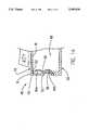
- FIG. 3is a side view of a representative portable computer which illustrates the keyboard structure in a perpendicular position to the computer housing that allows access to the interior of computer housing.
- FIG. 4is a partial top view of a representative portable computer which illustrates the keyboard structure in a transverse access position to the computer housing and shows a representative mother board within the interior of the computer housing.
- the present inventionincorporates a uniquely positionable keyboard structure 10 in a compact portable computer such as the representatively illustrated laptop or notebook computer 12.
- the keyboard structure 10has a front side portion 14; a top key side portion 16 with an interior side 18 (see FIG. 1A); and oppositely positioned left and right side walls 20 and 22 (FIG. 4) depending from the top key side portion 16.
- the computer 12includes an open-topped, relatively thin rectangular base housing 24 formed from a molded plastic material.
- the base housing 24has a bottom wall 26 adapted to rest upon a suitable horizontal support surface 28; a front wall 30, left and right side walls 32, 34 (see FIG. 4) extending rearwardly from the opposite ends of front wall 30; a rear side portion 36; and an upstanding rear wall 38 extending parallel to the front wall 30.
- a relatively thin rectangular plastic lid housing 40is conventionally secured to the rear side portion 38 of the base housing 36 in a manner permitting the lid housing 40 to be pivoted between its illustrated upright use position (see FIGS. 1 and 2) and a lowered storage/transport position (not shown) in which the lid housing 40 extends across and covers a top side of the base housing 24.
- the lid housing 40carries a monitor structure having a screen portion 42 extending across the front side of the lid housing 40 and visible to the computer user when the lid housing is in its upwardly pivoted use position.
- the keyboard structure 10is supported on the top side of the base housing 24 in a manner subsequently described.
- the now exposed keyboard structure 10is in its storage/transport orientation in which the top key side 16 thereof extends across the top side of the base housing 24 and is essentially parallel to the bottom wall 26 of the base housing 24 and thus the horizontal surface 28 upon which it rests.
- this horizontal orientation of the keyboardis the one that the computer user is limited to during typing thereon. This is in contrast to the more comfortable forwardly and downwardly sloping keyboard orientation available in separate desktop computer keyboard sections due to the incorporation therein of sloping housing udersides and/or downwardly pivotable rear support legs.
- the keyboard structure 10 in the computer 12may be tilted upwardly from its horizontal FIG. 1 position to the forwardly and downwardly sloping tilted use orientation shown in FIG. 2 in which the keyboard structure 10 is releasably locked to the base housing 24 and provides the computer user with considerably more comfortable typing hand and wrist positioning. It will be appreciated, of course, that the keyboard 10 may also be used in its horizontal orientation if so desired.
- the keyboard structure 10is mounted on the top side of base housing 24, between its front and rear walls 30 and 38.
- the front side 14 of the keyboard structure 10is pivotally connected to the base housing 24 by a hinge 44 which allows the keyboard structure 10 to be pivoted to an access position as shown in FIG. 3.
- This positionexposes the interior of the base housing 24 through an access opening 46.
- the usercan gain access to motherboard 47 to replace or exchange components 49 or expand the memory if so desired.
- This unique feature of the present inventionis particularly desirable when the motherboard is positioned in the upper portion of the interior of the base housing with the components facing upward toward the top of the computer. In such instances, where there is no access opening on the top of the computer as provided by the present invention or where the opening to the interior of the computer is positioned on the bottom side of the computer, accessibility to the component side of the motherboard can be achieved only by disassembling the unit.
- the present inventionprovides specially designed latch means which allow the keyboard to be tilted to a more desirable orientation.
- the latch meanswhich are discussed below, are not only light weight, but are extremely simple in design and cost effective. Thus, the advantages of having a tiltable keyboard are gained at little production cost and without the addition of any significant weight being added to the computer
- the computer of the present inventionincludes a simple latch assembly 48 for releasably holding the keyboard structure 10 in either the storage/transport position as shown in FIG. 1 or the tilted use position as shown in FIGS. 2A.
- latch assembly 48is resilient and includes a first generally planar wall portion 50 with a lower end portion 52 depending from at least one of the side walls 20, 22 of the keyboard structure 10, and a partially spherical inwardly projecting detent projection 56.
- the latch assembly 48also includes a second planar wall portion 58 extending upwardly from at least one of the side walls 32, 34 of the base housing 24 and having an upper end 62.
- Upper and lower detent depressions 64a and 64bare formed on the outer side of the second planar wall 58 and lockingly receive the detent projection 56 to releasably hold the lid 40 in a selected one of its tilted use and storage/transport positions.
- the detent structurescould be of varying designs which could function to releasably interlock the detent wall portions.
- more than two detent depressionscould be used to allow for varying degrees of keyboard slope.
- the latch assembly 48may also serve the dual purpose of a stop means for preventing the downward pivoting of the keyboard structure 10 past the storage/transport orientation.
- stop means 66is comprised of abutting portions of the keyboard structure 10 and the base housing 24. More specifically, the downward motion of the keyboard structure 10 is stopped by the upper end portion 62 of the second planar wall portion 58 coming into contact with the interior side 18 of the keyboard structure 10 and a bottom end of the first planar wall portion 50 simultaneously coming into contact an upwardly facing ledge 68 formed in at least one of the side walls 32, 34 of the base housing 10.
- the stop meanswould still be effective since the second end portion 62 of planar wall portion 58 would still come into contact with the interior side 18 of the keyboard 10. It is important to note that the latch means 48 on the keyboard structure 10 and the base housing 26 may be totally disengaged from one another so as to allow the keyboard structure 10 to be pivoted to the transverse access position shown in FIG. 3.
- keyboard structure 10In use, computer 12 is generally stored in the closed position and as such, the keyboard structure 10 will be in its stored/transport position as shown in FIG. 1. When keyboard structure 10 is in this position, the bottom end of the first planar wall portion 50 of the latch assembly 48 will be cooperatively engaged with the ledge 68 and the upper end portion 62 of the second planar wall portion 58 will be engaged with the interior side 18 of the keyboard structure 10 as shown in FIG. 1A. When use of the computer is desired, the lid 40 will be manually pivoted to its upright use position. The keyboard structure 10 can then be raised to its tilted use orientation as shown in FIG.
- the latch means 48may be disengaged by gently lifting up keyboard structure 10 and displacing the first planar wall portion 50 sufficiently to disengage the keyboard detent 56 from the base housing detent recess 64b.
- the keyboard structure 10When it is desired to store the computer, the keyboard structure 10 may be returned to its storage/transportation position by manually pressing down on the keyboard structure 10 with sufficient force to disengage the keyboard structure detent projection 56 from the base housing detent recess 64a. Again, in the alternative, the latch means 48 may be disengaged by gently pressing the keyboard structure 10 down and displacing the first planar wall portion 50. The stop means 66 will then prevent keyboard structure 10 from being pressed below the storage/transport position.
- the usermay lift up on keyboard structure 10 with sufficient force to disengage and separate the cooperating detent wall portions 50, 58. Once these detent wall portions are separated from one another, the user may pivot the keyboard structure 10 to its full upright access position as shown in FIG. 3. This access position provides the user with access to the motherboard 47 within the interior of the computer base housing 24.
- the keyboard structure 10is so positioned, components may be added or replaced as desired.
- the keyboard structure 10is manually lowered and sufficient force is applied to the keyboard structure 10 to releasably reengage the overlapping detent wall portions 50, 58 in either the tilted use position or the storage/transportation position.
Landscapes
- Engineering & Computer Science (AREA)
- Computer Hardware Design (AREA)
- Theoretical Computer Science (AREA)
- General Engineering & Computer Science (AREA)
- Physics & Mathematics (AREA)
- Human Computer Interaction (AREA)
- General Physics & Mathematics (AREA)
- Mathematical Physics (AREA)
- Input From Keyboards Or The Like (AREA)
- Casings For Electric Apparatus (AREA)
Abstract
Description
Claims (12)
Priority Applications (1)
| Application Number | Priority Date | Filing Date | Title |
|---|---|---|---|
| US08/183,018US5490036A (en) | 1994-01-18 | 1994-01-18 | Portable computer with tiltable keyboard structure having releasably engageable latch assembly members extending therefrom |
Applications Claiming Priority (1)
| Application Number | Priority Date | Filing Date | Title |
|---|---|---|---|
| US08/183,018US5490036A (en) | 1994-01-18 | 1994-01-18 | Portable computer with tiltable keyboard structure having releasably engageable latch assembly members extending therefrom |
Publications (1)
| Publication Number | Publication Date |
|---|---|
| US5490036Atrue US5490036A (en) | 1996-02-06 |
Family
ID=22671079
Family Applications (1)
| Application Number | Title | Priority Date | Filing Date |
|---|---|---|---|
| US08/183,018Expired - LifetimeUS5490036A (en) | 1994-01-18 | 1994-01-18 | Portable computer with tiltable keyboard structure having releasably engageable latch assembly members extending therefrom |
Country Status (1)
| Country | Link |
|---|---|
| US (1) | US5490036A (en) |
Cited By (40)
| Publication number | Priority date | Publication date | Assignee | Title |
|---|---|---|---|---|
| US5642257A (en)* | 1994-09-06 | 1997-06-24 | Citizen Watch Co., Ltd. | Attaching/detaching structure for a keyboard module in an information processing equipment |
| US5729480A (en)* | 1995-09-20 | 1998-03-17 | International Business Machine Corporation | Portable information processing apparatus |
| US5754395A (en)* | 1995-08-29 | 1998-05-19 | Acer Advanced Labs, Inc. | Ergonomic keyboard for a portable computer which is moveable between two positions |
| US5764474A (en)* | 1997-03-03 | 1998-06-09 | Compaq Computer Corporation | Portable computer with tilting keyboard that exposes pointing device |
| US5786775A (en)* | 1997-02-05 | 1998-07-28 | Compal Electronics, Inc. | Keyboard structure of a portable computer |
| US5966284A (en)* | 1996-07-31 | 1999-10-12 | Samsung Electronics Co., Ltd. | Keyboard mounting apparatus for a portable computer |
| EP0965077A4 (en)* | 1996-11-14 | 2000-01-19 | Teledyne Ind | AVIONIC SYSTEM WITH ACCESS BY ARTICULATED DISPLAY AND CONTROL PANEL |
| US6028768A (en)* | 1997-07-30 | 2000-02-22 | International Business Machines Corporation | Mechanism for deploying a keyboard for a portable computer |
| US6064564A (en)* | 1997-12-29 | 2000-05-16 | Compaq Computer Corporation | Portable computer with vertically positionable keyboard |
| US6091600A (en)* | 1997-06-30 | 2000-07-18 | Daewoo Telecom Ltd | Apparatus for tilting keyboard of portable computer |
| US6108196A (en)* | 1997-06-04 | 2000-08-22 | Samsung Electronics Co., Ltd. | Locking mechanism for notebook computer |
| US6115239A (en)* | 1997-06-03 | 2000-09-05 | Samsung Electronics Co., Ltd. | Locking mechanism for portable computer |
| US6147858A (en)* | 1998-03-31 | 2000-11-14 | Fujitsu Takamisawa Components Company | Keyboard unit and portable type information apparatus having the same |
| US6175504B1 (en) | 1998-09-17 | 2001-01-16 | Dell Usa, L.P. | Multi-member axial flexible circuit |
| US6292357B1 (en)* | 1999-10-07 | 2001-09-18 | International Business Machines Corporation | Laptop computer with ergonomically enhanced interface features |
| US6310766B1 (en) | 1997-03-15 | 2001-10-30 | Samsung Electronics Co., Ltd. | Latching apparatus for a portable computer |
| US6411504B2 (en) | 1999-08-25 | 2002-06-25 | Dell Usa, L.P. | Portable computer having latching hooks |
| US6573843B1 (en) | 1999-07-14 | 2003-06-03 | Micron Technology, Inc. | Snap-on keyboard and method of integrating keyboard |
| US6612668B2 (en) | 2001-08-24 | 2003-09-02 | Micron Technology, Inc. | Portable computer with articulate base |
| US6628507B2 (en)* | 2001-09-10 | 2003-09-30 | Wistron Corporation | Data processing device with liquid discharge capability |
| US20030206395A1 (en)* | 2002-05-02 | 2003-11-06 | International Business Machines Corporation | Rotational wrist pad operably linked to extendable legs of a computer having a backside surface configured for flush storage of the wrist pad |
| US20030213101A1 (en)* | 2002-05-15 | 2003-11-20 | First International Computer, Inc. | Hinge assembly for notebook computers |
| US6700773B1 (en) | 2000-11-03 | 2004-03-02 | Revolutionary Learning Systems, Inc. | Method and apparatus for implementing a configurable personal computing device |
| US20050146846A1 (en)* | 2004-01-02 | 2005-07-07 | Hon Hai Precision Industry Co., Ltd. | Mounting apparatus for motherboards |
| US20060034038A1 (en)* | 2004-08-11 | 2006-02-16 | Chunhong Hou | Including additional keys for mobile computers |
| USD517540S1 (en)* | 2004-09-10 | 2006-03-21 | Computer Dj Ltd. | Lap top computer |
| US20060125796A1 (en)* | 2004-12-10 | 2006-06-15 | Utz James R | Systems and methods for configuring user interface devices |
| US20070033972A1 (en)* | 2005-05-12 | 2007-02-15 | Lin-Kun Wang | Electronic Apparatus Capable of Conveniently Assembling and Disassembling a Key Module |
| USD594008S1 (en) | 2007-06-26 | 2009-06-09 | Hewlett-Packard Development Company, L.P. | Portable computer having a keyboard channel |
| US20100165567A1 (en)* | 2008-12-25 | 2010-07-01 | Shih Chia-Cheng | Portable electronic device with an input/output module to be driven to lift for improving heat dissipation when opening the screen module |
| US20100315773A1 (en)* | 2009-06-12 | 2010-12-16 | Hewlett-Packard Development Company, L.P. | Foot height adjustment system and method |
| CN102289294A (en)* | 2011-08-11 | 2011-12-21 | 张家港和乔电子有限公司 | Novel detachable keyboard |
| US20120134117A1 (en)* | 2010-11-30 | 2012-05-31 | Compal Electronics, Inc. | Portable electronic device |
| US20120300382A1 (en)* | 2011-05-23 | 2012-11-29 | Hon Hai Precision Industry Co., Ltd. | Notebook computer including a detachable keyboard |
| US9829927B2 (en)* | 2016-02-09 | 2017-11-28 | Google Llc | Laptop computer with cover rotatably attached to base that rotates to cover keyboard |
| CN109710032A (en)* | 2018-12-29 | 2019-05-03 | 安徽职业技术学院 | A kind of improved computer dust guard |
| US10429900B1 (en)* | 2018-04-02 | 2019-10-01 | Lenovo (Singapore) Pte. Ltd. | Coupled structure and electronic device |
| US10678300B2 (en)* | 2016-12-31 | 2020-06-09 | Lenovo (Singapore) Pte. Ltd. | Multi-fold computing device |
| US20240402765A1 (en)* | 2023-06-02 | 2024-12-05 | Acer Incorporated | Laptop computer with detachable touchpad module |
| US20250248004A1 (en)* | 2024-01-30 | 2025-07-31 | Dell Products L.P. | Two-in-one air shroud design |
Citations (1)
| Publication number | Priority date | Publication date | Assignee | Title |
|---|---|---|---|---|
| US5153589A (en)* | 1988-06-29 | 1992-10-06 | Ncr Corporation | Data processing terminal with removable keyboard module |
- 1994
- 1994-01-18USUS08/183,018patent/US5490036A/ennot_activeExpired - Lifetime
Patent Citations (1)
| Publication number | Priority date | Publication date | Assignee | Title |
|---|---|---|---|---|
| US5153589A (en)* | 1988-06-29 | 1992-10-06 | Ncr Corporation | Data processing terminal with removable keyboard module |
Non-Patent Citations (2)
| Title |
|---|
| IBM Technical Disclosure Bulletin, vol. 29, No. 8, pp. 3491 and 3492, Jan., 1987, "Access Method For Feature Expansion.". |
| IBM Technical Disclosure Bulletin, vol. 29, No. 8, pp. 3491 and 3492, Jan., 1987, Access Method For Feature Expansion. .* |
Cited By (49)
| Publication number | Priority date | Publication date | Assignee | Title |
|---|---|---|---|---|
| US5642257A (en)* | 1994-09-06 | 1997-06-24 | Citizen Watch Co., Ltd. | Attaching/detaching structure for a keyboard module in an information processing equipment |
| US5754395A (en)* | 1995-08-29 | 1998-05-19 | Acer Advanced Labs, Inc. | Ergonomic keyboard for a portable computer which is moveable between two positions |
| US5729480A (en)* | 1995-09-20 | 1998-03-17 | International Business Machine Corporation | Portable information processing apparatus |
| US5966284A (en)* | 1996-07-31 | 1999-10-12 | Samsung Electronics Co., Ltd. | Keyboard mounting apparatus for a portable computer |
| EP0965077A4 (en)* | 1996-11-14 | 2000-01-19 | Teledyne Ind | AVIONIC SYSTEM WITH ACCESS BY ARTICULATED DISPLAY AND CONTROL PANEL |
| US5786775A (en)* | 1997-02-05 | 1998-07-28 | Compal Electronics, Inc. | Keyboard structure of a portable computer |
| US5764474A (en)* | 1997-03-03 | 1998-06-09 | Compaq Computer Corporation | Portable computer with tilting keyboard that exposes pointing device |
| US6310766B1 (en) | 1997-03-15 | 2001-10-30 | Samsung Electronics Co., Ltd. | Latching apparatus for a portable computer |
| US6115239A (en)* | 1997-06-03 | 2000-09-05 | Samsung Electronics Co., Ltd. | Locking mechanism for portable computer |
| US6108196A (en)* | 1997-06-04 | 2000-08-22 | Samsung Electronics Co., Ltd. | Locking mechanism for notebook computer |
| US6091600A (en)* | 1997-06-30 | 2000-07-18 | Daewoo Telecom Ltd | Apparatus for tilting keyboard of portable computer |
| US6028768A (en)* | 1997-07-30 | 2000-02-22 | International Business Machines Corporation | Mechanism for deploying a keyboard for a portable computer |
| US6064564A (en)* | 1997-12-29 | 2000-05-16 | Compaq Computer Corporation | Portable computer with vertically positionable keyboard |
| US6307736B1 (en) | 1997-12-29 | 2001-10-23 | Compaq Computer Corporation | Portable computer with vertically positionable keyboard |
| US6147858A (en)* | 1998-03-31 | 2000-11-14 | Fujitsu Takamisawa Components Company | Keyboard unit and portable type information apparatus having the same |
| US6175504B1 (en) | 1998-09-17 | 2001-01-16 | Dell Usa, L.P. | Multi-member axial flexible circuit |
| US6573843B1 (en) | 1999-07-14 | 2003-06-03 | Micron Technology, Inc. | Snap-on keyboard and method of integrating keyboard |
| US6411504B2 (en) | 1999-08-25 | 2002-06-25 | Dell Usa, L.P. | Portable computer having latching hooks |
| US6292357B1 (en)* | 1999-10-07 | 2001-09-18 | International Business Machines Corporation | Laptop computer with ergonomically enhanced interface features |
| US6344967B2 (en)* | 1999-10-07 | 2002-02-05 | International Business Machines Corporation | Laptop computer with ergonomically enhanced interface features |
| US6404621B2 (en)* | 1999-10-07 | 2002-06-11 | International Business Machines Corporation | Laptop computer with ergonomically enhanced interface features |
| US6700773B1 (en) | 2000-11-03 | 2004-03-02 | Revolutionary Learning Systems, Inc. | Method and apparatus for implementing a configurable personal computing device |
| US6612668B2 (en) | 2001-08-24 | 2003-09-02 | Micron Technology, Inc. | Portable computer with articulate base |
| US6628507B2 (en)* | 2001-09-10 | 2003-09-30 | Wistron Corporation | Data processing device with liquid discharge capability |
| US20030206395A1 (en)* | 2002-05-02 | 2003-11-06 | International Business Machines Corporation | Rotational wrist pad operably linked to extendable legs of a computer having a backside surface configured for flush storage of the wrist pad |
| US6654230B1 (en)* | 2002-05-02 | 2003-11-25 | International Business Machines Corp. | Rotational wrist pad operably linked to extendable legs of a computer having a backside surface configured for flush storage of the wrist pad |
| US20030213101A1 (en)* | 2002-05-15 | 2003-11-20 | First International Computer, Inc. | Hinge assembly for notebook computers |
| US6895638B2 (en)* | 2002-05-15 | 2005-05-24 | First International Computer Inc. | Hinge assembly for notebook computers |
| US20050146846A1 (en)* | 2004-01-02 | 2005-07-07 | Hon Hai Precision Industry Co., Ltd. | Mounting apparatus for motherboards |
| US7064958B2 (en)* | 2004-01-02 | 2006-06-20 | Hon Hai Precision Industry Co., Ltd | Mounting apparatus for motherboards |
| US20060034038A1 (en)* | 2004-08-11 | 2006-02-16 | Chunhong Hou | Including additional keys for mobile computers |
| USD517540S1 (en)* | 2004-09-10 | 2006-03-21 | Computer Dj Ltd. | Lap top computer |
| US20060125796A1 (en)* | 2004-12-10 | 2006-06-15 | Utz James R | Systems and methods for configuring user interface devices |
| US20070033972A1 (en)* | 2005-05-12 | 2007-02-15 | Lin-Kun Wang | Electronic Apparatus Capable of Conveniently Assembling and Disassembling a Key Module |
| US7447008B2 (en)* | 2005-05-12 | 2008-11-04 | Qisda Corporation | Electronic apparatus capable of conveniently assembling and disassembling a key module |
| USD594008S1 (en) | 2007-06-26 | 2009-06-09 | Hewlett-Packard Development Company, L.P. | Portable computer having a keyboard channel |
| US20100165567A1 (en)* | 2008-12-25 | 2010-07-01 | Shih Chia-Cheng | Portable electronic device with an input/output module to be driven to lift for improving heat dissipation when opening the screen module |
| US20100315773A1 (en)* | 2009-06-12 | 2010-12-16 | Hewlett-Packard Development Company, L.P. | Foot height adjustment system and method |
| US20120134117A1 (en)* | 2010-11-30 | 2012-05-31 | Compal Electronics, Inc. | Portable electronic device |
| US8451624B2 (en)* | 2010-11-30 | 2013-05-28 | Compal Electronics, Inc. | Portable electronic device |
| US20120300382A1 (en)* | 2011-05-23 | 2012-11-29 | Hon Hai Precision Industry Co., Ltd. | Notebook computer including a detachable keyboard |
| CN102289294A (en)* | 2011-08-11 | 2011-12-21 | 张家港和乔电子有限公司 | Novel detachable keyboard |
| CN102289294B (en)* | 2011-08-11 | 2013-11-06 | 张家港和乔电子有限公司 | Novel detachable keyboard |
| US9829927B2 (en)* | 2016-02-09 | 2017-11-28 | Google Llc | Laptop computer with cover rotatably attached to base that rotates to cover keyboard |
| US10678300B2 (en)* | 2016-12-31 | 2020-06-09 | Lenovo (Singapore) Pte. Ltd. | Multi-fold computing device |
| US10429900B1 (en)* | 2018-04-02 | 2019-10-01 | Lenovo (Singapore) Pte. Ltd. | Coupled structure and electronic device |
| CN109710032A (en)* | 2018-12-29 | 2019-05-03 | 安徽职业技术学院 | A kind of improved computer dust guard |
| US20240402765A1 (en)* | 2023-06-02 | 2024-12-05 | Acer Incorporated | Laptop computer with detachable touchpad module |
| US20250248004A1 (en)* | 2024-01-30 | 2025-07-31 | Dell Products L.P. | Two-in-one air shroud design |
Similar Documents
| Publication | Publication Date | Title |
|---|---|---|
| US5490036A (en) | Portable computer with tiltable keyboard structure having releasably engageable latch assembly members extending therefrom | |
| US5629832A (en) | Electronic device keyboard with pivot bar tilt mechanism | |
| US5539615A (en) | Notebook computer keyboard with slot-supported sliding pin tilt mechanism | |
| US6903927B2 (en) | Convertible mobile computing device | |
| US5375076A (en) | Combined notepad and notebook computer | |
| US6975507B2 (en) | Structure of notebook computer | |
| US5490037A (en) | Flexing keyboard structure for a notebook computer | |
| US6104604A (en) | Modular keyboard | |
| US6700773B1 (en) | Method and apparatus for implementing a configurable personal computing device | |
| KR100392245B1 (en) | Flexibly interfaceable portable computing device | |
| US5548478A (en) | Portable computing device having an adjustable hinge | |
| US7030859B2 (en) | Flat-type computer with keyboard | |
| US5825614A (en) | Compact personal computer with LCD monitor | |
| US7298610B2 (en) | Supporting apparatus for portable computer | |
| US5894406A (en) | Elevated separate external keyboard apparatus for use with portable computer | |
| US6912121B2 (en) | Personal computer device having constant tilt display with adjustable height | |
| JP2669592B2 (en) | Pen input type portable computer, display device and setting method | |
| US6462937B1 (en) | Computer having an integrated gaming control pad | |
| US6332658B1 (en) | Lock device for expansion unit in computer | |
| JPH0719186B2 (en) | Computer and display device with input function | |
| US20030100338A1 (en) | Personal digital assistant cover with an integrated keypad | |
| US20030063059A1 (en) | Method and apparatus for reusing a flat panel monitor | |
| US5729480A (en) | Portable information processing apparatus | |
| US6778385B2 (en) | Portable computer with removable bottom component housing | |
| US6023411A (en) | Modular docking tray and method |
Legal Events
| Date | Code | Title | Description |
|---|---|---|---|
| AS | Assignment | Owner name:DELL USA, L.P., TEXAS Free format text:ASSIGNMENT OF ASSIGNORS INTEREST;ASSIGNORS:LIN, JENG-HUA;BUSCH, JOHN P.;HUFFMAN, JAMES W.;REEL/FRAME:006844/0267 Effective date:19940114 | |
| STCF | Information on status: patent grant | Free format text:PATENTED CASE | |
| FPAY | Fee payment | Year of fee payment:4 | |
| FEPP | Fee payment procedure | Free format text:PAYOR NUMBER ASSIGNED (ORIGINAL EVENT CODE: ASPN); ENTITY STATUS OF PATENT OWNER: LARGE ENTITY | |
| FPAY | Fee payment | Year of fee payment:8 | |
| FPAY | Fee payment | Year of fee payment:12 | |
| AS | Assignment | Owner name:BANK OF AMERICA, N.A., AS ADMINISTRATIVE AGENT, TE Free format text:PATENT SECURITY AGREEMENT (ABL);ASSIGNORS:DELL INC.;APPASSURE SOFTWARE, INC.;ASAP SOFTWARE EXPRESS, INC.;AND OTHERS;REEL/FRAME:031898/0001 Effective date:20131029 Owner name:BANK OF NEW YORK MELLON TRUST COMPANY, N.A., AS FIRST LIEN COLLATERAL AGENT, TEXAS Free format text:PATENT SECURITY AGREEMENT (NOTES);ASSIGNORS:APPASSURE SOFTWARE, INC.;ASAP SOFTWARE EXPRESS, INC.;BOOMI, INC.;AND OTHERS;REEL/FRAME:031897/0348 Effective date:20131029 Owner name:BANK OF AMERICA, N.A., AS COLLATERAL AGENT, NORTH CAROLINA Free format text:PATENT SECURITY AGREEMENT (TERM LOAN);ASSIGNORS:DELL INC.;APPASSURE SOFTWARE, INC.;ASAP SOFTWARE EXPRESS, INC.;AND OTHERS;REEL/FRAME:031899/0261 Effective date:20131029 Owner name:BANK OF AMERICA, N.A., AS ADMINISTRATIVE AGENT, TEXAS Free format text:PATENT SECURITY AGREEMENT (ABL);ASSIGNORS:DELL INC.;APPASSURE SOFTWARE, INC.;ASAP SOFTWARE EXPRESS, INC.;AND OTHERS;REEL/FRAME:031898/0001 Effective date:20131029 Owner name:BANK OF NEW YORK MELLON TRUST COMPANY, N.A., AS FI Free format text:PATENT SECURITY AGREEMENT (NOTES);ASSIGNORS:APPASSURE SOFTWARE, INC.;ASAP SOFTWARE EXPRESS, INC.;BOOMI, INC.;AND OTHERS;REEL/FRAME:031897/0348 Effective date:20131029 Owner name:BANK OF AMERICA, N.A., AS COLLATERAL AGENT, NORTH Free format text:PATENT SECURITY AGREEMENT (TERM LOAN);ASSIGNORS:DELL INC.;APPASSURE SOFTWARE, INC.;ASAP SOFTWARE EXPRESS, INC.;AND OTHERS;REEL/FRAME:031899/0261 Effective date:20131029 | |
| AS | Assignment | Owner name:DELL USA L.P., TEXAS Free format text:RELEASE BY SECURED PARTY;ASSIGNOR:BANK OF AMERICA, N.A., AS ADMINISTRATIVE AGENT;REEL/FRAME:040065/0216 Effective date:20160907 Owner name:APPASSURE SOFTWARE, INC., VIRGINIA Free format text:RELEASE BY SECURED PARTY;ASSIGNOR:BANK OF AMERICA, N.A., AS ADMINISTRATIVE AGENT;REEL/FRAME:040065/0216 Effective date:20160907 Owner name:ASAP SOFTWARE EXPRESS, INC., ILLINOIS Free format text:RELEASE BY SECURED PARTY;ASSIGNOR:BANK OF AMERICA, N.A., AS ADMINISTRATIVE AGENT;REEL/FRAME:040065/0216 Effective date:20160907 Owner name:DELL INC., TEXAS Free format text:RELEASE BY SECURED PARTY;ASSIGNOR:BANK OF AMERICA, N.A., AS ADMINISTRATIVE AGENT;REEL/FRAME:040065/0216 Effective date:20160907 Owner name:CREDANT TECHNOLOGIES, INC., TEXAS Free format text:RELEASE BY SECURED PARTY;ASSIGNOR:BANK OF AMERICA, N.A., AS ADMINISTRATIVE AGENT;REEL/FRAME:040065/0216 Effective date:20160907 Owner name:FORCE10 NETWORKS, INC., CALIFORNIA Free format text:RELEASE BY SECURED PARTY;ASSIGNOR:BANK OF AMERICA, N.A., AS ADMINISTRATIVE AGENT;REEL/FRAME:040065/0216 Effective date:20160907 Owner name:PEROT SYSTEMS CORPORATION, TEXAS Free format text:RELEASE BY SECURED PARTY;ASSIGNOR:BANK OF AMERICA, N.A., AS ADMINISTRATIVE AGENT;REEL/FRAME:040065/0216 Effective date:20160907 Owner name:COMPELLANT TECHNOLOGIES, INC., MINNESOTA Free format text:RELEASE BY SECURED PARTY;ASSIGNOR:BANK OF AMERICA, N.A., AS ADMINISTRATIVE AGENT;REEL/FRAME:040065/0216 Effective date:20160907 Owner name:DELL MARKETING L.P., TEXAS Free format text:RELEASE BY SECURED PARTY;ASSIGNOR:BANK OF AMERICA, N.A., AS ADMINISTRATIVE AGENT;REEL/FRAME:040065/0216 Effective date:20160907 Owner name:DELL SOFTWARE INC., CALIFORNIA Free format text:RELEASE BY SECURED PARTY;ASSIGNOR:BANK OF AMERICA, N.A., AS ADMINISTRATIVE AGENT;REEL/FRAME:040065/0216 Effective date:20160907 Owner name:SECUREWORKS, INC., GEORGIA Free format text:RELEASE BY SECURED PARTY;ASSIGNOR:BANK OF AMERICA, N.A., AS ADMINISTRATIVE AGENT;REEL/FRAME:040065/0216 Effective date:20160907 Owner name:WYSE TECHNOLOGY L.L.C., CALIFORNIA Free format text:RELEASE BY SECURED PARTY;ASSIGNOR:BANK OF AMERICA, N.A., AS ADMINISTRATIVE AGENT;REEL/FRAME:040065/0216 Effective date:20160907 Owner name:DELL PRODUCTS L.P., TEXAS Free format text:RELEASE BY SECURED PARTY;ASSIGNOR:BANK OF AMERICA, N.A., AS ADMINISTRATIVE AGENT;REEL/FRAME:040065/0216 Effective date:20160907 | |
| AS | Assignment | Owner name:DELL INC., TEXAS Free format text:RELEASE BY SECURED PARTY;ASSIGNOR:BANK OF AMERICA, N.A., AS COLLATERAL AGENT;REEL/FRAME:040040/0001 Effective date:20160907 Owner name:PEROT SYSTEMS CORPORATION, TEXAS Free format text:RELEASE BY SECURED PARTY;ASSIGNOR:BANK OF AMERICA, N.A., AS COLLATERAL AGENT;REEL/FRAME:040040/0001 Effective date:20160907 Owner name:COMPELLENT TECHNOLOGIES, INC., MINNESOTA Free format text:RELEASE BY SECURED PARTY;ASSIGNOR:BANK OF AMERICA, N.A., AS COLLATERAL AGENT;REEL/FRAME:040040/0001 Effective date:20160907 Owner name:WYSE TECHNOLOGY L.L.C., CALIFORNIA Free format text:RELEASE BY SECURED PARTY;ASSIGNOR:BANK OF AMERICA, N.A., AS COLLATERAL AGENT;REEL/FRAME:040040/0001 Effective date:20160907 Owner name:SECUREWORKS, INC., GEORGIA Free format text:RELEASE BY SECURED PARTY;ASSIGNOR:BANK OF AMERICA, N.A., AS COLLATERAL AGENT;REEL/FRAME:040040/0001 Effective date:20160907 Owner name:DELL SOFTWARE INC., CALIFORNIA Free format text:RELEASE BY SECURED PARTY;ASSIGNOR:BANK OF AMERICA, N.A., AS COLLATERAL AGENT;REEL/FRAME:040040/0001 Effective date:20160907 Owner name:ASAP SOFTWARE EXPRESS, INC., ILLINOIS Free format text:RELEASE BY SECURED PARTY;ASSIGNOR:BANK OF AMERICA, N.A., AS COLLATERAL AGENT;REEL/FRAME:040040/0001 Effective date:20160907 Owner name:CREDANT TECHNOLOGIES, INC., TEXAS Free format text:RELEASE BY SECURED PARTY;ASSIGNOR:BANK OF AMERICA, N.A., AS COLLATERAL AGENT;REEL/FRAME:040040/0001 Effective date:20160907 Owner name:APPASSURE SOFTWARE, INC., VIRGINIA Free format text:RELEASE BY SECURED PARTY;ASSIGNOR:BANK OF AMERICA, N.A., AS COLLATERAL AGENT;REEL/FRAME:040040/0001 Effective date:20160907 Owner name:DELL USA L.P., TEXAS Free format text:RELEASE BY SECURED PARTY;ASSIGNOR:BANK OF AMERICA, N.A., AS COLLATERAL AGENT;REEL/FRAME:040040/0001 Effective date:20160907 Owner name:DELL MARKETING L.P., TEXAS Free format text:RELEASE BY SECURED PARTY;ASSIGNOR:BANK OF AMERICA, N.A., AS COLLATERAL AGENT;REEL/FRAME:040040/0001 Effective date:20160907 Owner name:DELL PRODUCTS L.P., TEXAS Free format text:RELEASE BY SECURED PARTY;ASSIGNOR:BANK OF AMERICA, N.A., AS COLLATERAL AGENT;REEL/FRAME:040040/0001 Effective date:20160907 Owner name:FORCE10 NETWORKS, INC., CALIFORNIA Free format text:RELEASE BY SECURED PARTY;ASSIGNOR:BANK OF AMERICA, N.A., AS COLLATERAL AGENT;REEL/FRAME:040040/0001 Effective date:20160907 Owner name:DELL USA L.P., TEXAS Free format text:RELEASE BY SECURED PARTY;ASSIGNOR:BANK OF NEW YORK MELLON TRUST COMPANY, N.A., AS COLLATERAL AGENT;REEL/FRAME:040065/0618 Effective date:20160907 Owner name:WYSE TECHNOLOGY L.L.C., CALIFORNIA Free format text:RELEASE BY SECURED PARTY;ASSIGNOR:BANK OF NEW YORK MELLON TRUST COMPANY, N.A., AS COLLATERAL AGENT;REEL/FRAME:040065/0618 Effective date:20160907 Owner name:DELL SOFTWARE INC., CALIFORNIA Free format text:RELEASE BY SECURED PARTY;ASSIGNOR:BANK OF NEW YORK MELLON TRUST COMPANY, N.A., AS COLLATERAL AGENT;REEL/FRAME:040065/0618 Effective date:20160907 Owner name:SECUREWORKS, INC., GEORGIA Free format text:RELEASE BY SECURED PARTY;ASSIGNOR:BANK OF NEW YORK MELLON TRUST COMPANY, N.A., AS COLLATERAL AGENT;REEL/FRAME:040065/0618 Effective date:20160907 Owner name:COMPELLENT TECHNOLOGIES, INC., MINNESOTA Free format text:RELEASE BY SECURED PARTY;ASSIGNOR:BANK OF NEW YORK MELLON TRUST COMPANY, N.A., AS COLLATERAL AGENT;REEL/FRAME:040065/0618 Effective date:20160907 Owner name:DELL PRODUCTS L.P., TEXAS Free format text:RELEASE BY SECURED PARTY;ASSIGNOR:BANK OF NEW YORK MELLON TRUST COMPANY, N.A., AS COLLATERAL AGENT;REEL/FRAME:040065/0618 Effective date:20160907 Owner name:DELL INC., TEXAS Free format text:RELEASE BY SECURED PARTY;ASSIGNOR:BANK OF NEW YORK MELLON TRUST COMPANY, N.A., AS COLLATERAL AGENT;REEL/FRAME:040065/0618 Effective date:20160907 Owner name:ASAP SOFTWARE EXPRESS, INC., ILLINOIS Free format text:RELEASE BY SECURED PARTY;ASSIGNOR:BANK OF NEW YORK MELLON TRUST COMPANY, N.A., AS COLLATERAL AGENT;REEL/FRAME:040065/0618 Effective date:20160907 Owner name:DELL MARKETING L.P., TEXAS Free format text:RELEASE BY SECURED PARTY;ASSIGNOR:BANK OF NEW YORK MELLON TRUST COMPANY, N.A., AS COLLATERAL AGENT;REEL/FRAME:040065/0618 Effective date:20160907 Owner name:FORCE10 NETWORKS, INC., CALIFORNIA Free format text:RELEASE BY SECURED PARTY;ASSIGNOR:BANK OF NEW YORK MELLON TRUST COMPANY, N.A., AS COLLATERAL AGENT;REEL/FRAME:040065/0618 Effective date:20160907 Owner name:CREDANT TECHNOLOGIES, INC., TEXAS Free format text:RELEASE BY SECURED PARTY;ASSIGNOR:BANK OF NEW YORK MELLON TRUST COMPANY, N.A., AS COLLATERAL AGENT;REEL/FRAME:040065/0618 Effective date:20160907 Owner name:APPASSURE SOFTWARE, INC., VIRGINIA Free format text:RELEASE BY SECURED PARTY;ASSIGNOR:BANK OF NEW YORK MELLON TRUST COMPANY, N.A., AS COLLATERAL AGENT;REEL/FRAME:040065/0618 Effective date:20160907 Owner name:PEROT SYSTEMS CORPORATION, TEXAS Free format text:RELEASE BY SECURED PARTY;ASSIGNOR:BANK OF NEW YORK MELLON TRUST COMPANY, N.A., AS COLLATERAL AGENT;REEL/FRAME:040065/0618 Effective date:20160907 |