US5490033A - Electrostatic discharge protection device - Google Patents
Electrostatic discharge protection deviceDownload PDFInfo
- Publication number
- US5490033A US5490033AUS08/234,917US23491794AUS5490033AUS 5490033 AUS5490033 AUS 5490033AUS 23491794 AUS23491794 AUS 23491794AUS 5490033 AUS5490033 AUS 5490033A
- Authority
- US
- United States
- Prior art keywords
- electrostatic discharge
- protection device
- discharge protection
- core
- complimentary
- Prior art date
- Legal status (The legal status is an assumption and is not a legal conclusion. Google has not performed a legal analysis and makes no representation as to the accuracy of the status listed.)
- Expired - Fee Related
Links
Images


Classifications
- H—ELECTRICITY
- H01—ELECTRIC ELEMENTS
- H01R—ELECTRICALLY-CONDUCTIVE CONNECTIONS; STRUCTURAL ASSOCIATIONS OF A PLURALITY OF MUTUALLY-INSULATED ELECTRICAL CONNECTING ELEMENTS; COUPLING DEVICES; CURRENT COLLECTORS
- H01R24/00—Two-part coupling devices, or either of their cooperating parts, characterised by their overall structure
- H01R24/38—Two-part coupling devices, or either of their cooperating parts, characterised by their overall structure having concentrically or coaxially arranged contacts
- H01R24/40—Two-part coupling devices, or either of their cooperating parts, characterised by their overall structure having concentrically or coaxially arranged contacts specially adapted for high frequency
- H01R24/42—Two-part coupling devices, or either of their cooperating parts, characterised by their overall structure having concentrically or coaxially arranged contacts specially adapted for high frequency comprising impedance matching means or electrical components, e.g. filters or switches
- H01R24/46—Two-part coupling devices, or either of their cooperating parts, characterised by their overall structure having concentrically or coaxially arranged contacts specially adapted for high frequency comprising impedance matching means or electrical components, e.g. filters or switches comprising switches
- H—ELECTRICITY
- H01—ELECTRIC ELEMENTS
- H01R—ELECTRICALLY-CONDUCTIVE CONNECTIONS; STRUCTURAL ASSOCIATIONS OF A PLURALITY OF MUTUALLY-INSULATED ELECTRICAL CONNECTING ELEMENTS; COUPLING DEVICES; CURRENT COLLECTORS
- H01R13/00—Details of coupling devices of the kinds covered by groups H01R12/70 or H01R24/00 - H01R33/00
- H01R13/648—Protective earth or shield arrangements on coupling devices, e.g. anti-static shielding
- H01R13/6485—Electrostatic discharge protection
- H—ELECTRICITY
- H01—ELECTRIC ELEMENTS
- H01R—ELECTRICALLY-CONDUCTIVE CONNECTIONS; STRUCTURAL ASSOCIATIONS OF A PLURALITY OF MUTUALLY-INSULATED ELECTRICAL CONNECTING ELEMENTS; COUPLING DEVICES; CURRENT COLLECTORS
- H01R13/00—Details of coupling devices of the kinds covered by groups H01R12/70 or H01R24/00 - H01R33/00
- H01R13/66—Structural association with built-in electrical component
- H01R13/70—Structural association with built-in electrical component with built-in switch
- H01R13/703—Structural association with built-in electrical component with built-in switch operated by engagement or disengagement of coupling parts, e.g. dual-continuity coupling part
- H—ELECTRICITY
- H01—ELECTRIC ELEMENTS
- H01R—ELECTRICALLY-CONDUCTIVE CONNECTIONS; STRUCTURAL ASSOCIATIONS OF A PLURALITY OF MUTUALLY-INSULATED ELECTRICAL CONNECTING ELEMENTS; COUPLING DEVICES; CURRENT COLLECTORS
- H01R2103/00—Two poles
- H—ELECTRICITY
- H01—ELECTRIC ELEMENTS
- H01R—ELECTRICALLY-CONDUCTIVE CONNECTIONS; STRUCTURAL ASSOCIATIONS OF A PLURALITY OF MUTUALLY-INSULATED ELECTRICAL CONNECTING ELEMENTS; COUPLING DEVICES; CURRENT COLLECTORS
- H01R31/00—Coupling parts supported only by co-operation with counterpart
- H01R31/08—Short-circuiting members for bridging contacts in a counterpart
Definitions
- the present inventionrelates generally to electrostatic discharge protection devices. More particularly, the invention relates to electrostatic discharge protection devices for connector-receptor assemblies where the electrostatic discharge protection device connects ground and core conductors to inhibit electrostatic charge accumulation when the connector-receptor are disconnected, and automatically disconnects this ground connection upon operative combination of the connector-receptor.
- Electrostatic chargeis a stationary electric charge which accumulates on various surfaces.
- An electrostatic dischargeoccurs when the electrostatic charge becomes substantial enough to overcome a dielectric material between the charge and another surface of a lower electrical potential.
- An example of such a dischargeis naturally occurring lightning.
- Electrostatic discharge in the realm of electronicscan be devastating to microelectronic devices.
- a sharp voltage spike caused by an electrostatic dischargecan cause permanent and costly damage to individual precision devices, such as random access memory (RAM) or other semiconductor devices, inter alia.
- Circuit designs which are specially susceptible to electrostatic dischargeare those having external connections.
- a thicknet local area network (LAN) card in a personal computeris often designed with a BNC type connector extending to the exterior of the personal computer.
- a coaxial cable having a complimentary BNC connectoris attached to the BNC connector on the card to provide access to a network. While the coaxial cable is unattached, electrostatic discharge can occur destroying the devices or components on the card without any physical manifestation leading to costly hardware diagnostics and subsequent repairs.
- an electrostatic discharge protection deviceoperates to automatically open a short between selected conductors upon connection to a mating connector.
- the aforementioned and other objectsare achieved by the invention which provides, in one aspect, an electrostatic discharge protection device.
- the electrostatic discharge protection deviceis useful with a connector having first and second complimentary members which are adapted to be joined electrically connecting corresponding parts of multiple high frequency cables.
- High frequency cablesgenerally have a ground conductor formed in a tubular arrangement to encompass one or more core conductors.
- the ground conductoris adapted to be electrically grounded and is spaced apart from the core conductors by a dielectric material medium for providing electrical insulation between the core conductors and the ground conductor.
- Each of two complimentary members of the connectorhave a ground shell which is electrically connected to the ground conductor and have at least one or more core connector where each core connector electrically connected to a corresponding one of one or more core conductors.
- the electrostatic discharge protection devicecomprises grounding means which is disposed within the ground shell of the first complimentary member.
- the grounding means in the first complimentary memberis in an operative position establishing a shunt between the ground shell and each of the one or more core connectors. This shunt places the ground shell and such core connectors of the first complimentary member at a substantially equivalent electrical potential to prevent electrostatic discharge therebetween.
- the grounding meansautomatically is displaced into an inoperative position where the shunt is disconnected, allowing the ground shell and such one or more core conductors of the first complimentary member to become substantially electrically isolated.
- the electrostatic discharge protection devicecan be used with a male-type or female-type connector and is reusable in that the first complimentary member and the second complimentary member can be joined and disconnected multiple times without detriment to the operation of the grounding member.
- the inventionprovides methods in accord with the apparatus described above.
- the aforementioned and other aspects of the inventionare evident in the drawings and in the description that follows.
- FIG. 1shows an exploded perspective view of a BNC-type electrical connector-receptor and an electrostatic discharge protection device in accordance with the invention
- FIG. 2shows perspective view of a BNC-type connector utilizing the electrostatic discharge protection device of FIG. 1.
- FIG. 3shows perspective view of a BNC-type connector utilizing the electrostatic discharge protection device of FIG. 4 in full engagement with a receptor.
- FIG. 4shows an exploded perspective view of a BNC-type electrical connector-receptor and an electrostatic discharge protection device in accordance with the invention
- FIG. 5shows perspective view of a BNC-type receptor utilizing the electrostatic discharge protection device of FIG. 4.
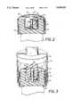
- FIG. 6shows cross-sectional view of a BNC-type connector in full engagement with a receptor utilizing the electrostatic discharge protection device of FIG. 4.
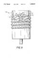
- FIG. 7shows an exploded perspective view of a SMA-type electrical connector-receptor and an electrostatic discharge protection device in accordance with the invention
- FIG. 8shows perspective view of a SMA-type receptor utilizing the electrostatic discharge protection device of FIG. 7.
- FIG. 9shows perspective view of a SMA-type connector in full engagement with a receptor utilizing the electrostatic discharge protection device of FIG. 7.
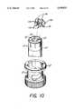
- FIG. 10shows a perspective view of a BNC-type connector for a twinaxial cable with an electrostatic discharge protection device in accordance with the invention.
- High frequency cableis generally designed with one outside conductor surrounding one or more core conductors.
- the outside conductoris generally grounded such that it remains electrically neutral. In this way, the enclosed core conductors are shielded from electromagnetic signals and noise.
- Connecting two or more of these high frequency cablesrequires connectors adapted for such a conductor arrangement. Examples of such connectors are known in the art as a subminiature connector (hereinafter "SMA”) and a bayonet navy connector (hereinafter “BNC”) connector, both of which are illustrated herein.
- SMAsubminiature connector
- BNCbayonet navy connector
- the connector 20in one embodiment is a BNC connector having a cylindrical housing 21 for securing the receptor 30 upon insertion.
- a cable terminator 23which is electrically connected to a high frequency cable.
- the high frequency cableis a coaxial cable consisting of a conducting outer metal tube enclosing and insulated from a central conducting core. Though this is the exemplified form, other high frequency shielded cables may be substituted without detriment to the invention and therefore the use of coaxial cable should be considered illustrative and not restrictive.
- the cable terminator 23is arranged for a coaxial cable as previously discussed.
- a ground conductor or shell 22is in electrical communication with the outer metal tube 22a of the coaxial cable and is arranged in the connector 20 in a manner similar to that of the outer metal tube in a coaxial cable.
- the outer metal tube 22a of a coaxial cableis generally held electrically neutral, or ground, which provides a shield for inner conductors. Outside electromagnetic interference strikes the outside metal tube and is grounded thus stopping penetration into the cable.
- the ground conductor 22being in electrical communication with the outside metal tube, is also electrically neutral.
- a dielectric material ring 24is enclosed by the ground conductor.
- the dielectric material ring 24is an electrical insulator ensuring that conduction between the ground conductor 22 and central conductor is inhibited.
- An open bore 26is enclosed by the dielectric material ring 24 for receiving the receptor as further described herein.
- the core connector 28is a hollow pin which receives and is electrically connected to the central conducting core of the coaxial cable which ultimately connects to other electrical components remotely stationed with respect to the connector 20 in a well known manner.
- the connector 20is adapted for ready insertion or withdrawal from the complimentary receptor 30 which is also a termination point for a coaxial cable.
- the receptor 30mates with the connector 20 in such a way as to allow electrical communication between the coaxial cables. In the BNC connector, this is accomplished by inserting two pegs 31 extending radially outward from the receptor following a diameter of the cable into a slot 25 in the cylindrical housing 21. The receptor 30 is pushed down into the connector 20 such that the pegs 31 follow the slot 25 into a locked position. Withdrawal is accomplished following a similar process, but reversed.
- a ground shell 32passes between the cylindrical housing 21 and the ground conductor 22.
- the ground shell 32may or may not make mechanical contact with the ground conductor 22, but in either event, conduction is allowed through the cylindrical housing 21 which is in electrical communication with the ground conductor 22.
- the receptor 30uses a dielectric material to separate the conductors.
- a dielectric material ring 34is formed with an outside diameter slightly less than the diameter of the bore 26 of the connector such that upon insertion the dielectric material ring 34 fits within the bore 26.
- a ferrule or complimentary connector 38which is in electrical communication with the central conducting core of the coaxial cable attached to the receptor 30.
- the ferulehas an inside diameter which is which is substantially the same as the outside diameter of the core connector 28. As the core connector 28 is inserted into the ferrule 38, the ferrule expands due to radial pressure caused by the mechanical contact with the core conductor 28. This mechanical contact establishes electrical continuity within the coaxial cables thus electrically connecting same.
- the electrostatic discharge protection device 10 of the inventionis a conductive device in the form of a grounding member or means that operates with the above-described connector-receptor relationship to ground electrostatic charge from the central conducting core of the coaxial cable gathered while in an unconnected state.
- the electrostatic discharge protection device 10accomplishes this by creating a shunt between the outer metal tube 22 and the central core connector 28 thus making the central conducting core electrically neutral and stopping propagation of electrostatic charge or noise to any attached electronic components.
- electrostatic discharge protection device 10is fabricated to be electrically conductive while having a high spring constant providing resiliency.
- a spring alloy of beryllium copperis used.
- the electrostatic discharge protection device 10may be fabricated of conductive plastic or other material having a higher impedance, or a contact on the electrostatic discharge protection device can be coated with a resistive material to increase overall impedance. Since a characteristic of electrostatic discharge is high voltage with low current, a higher impedance has minimal effect upon the protective capabilities of the electrostatic discharge protection device.
- the electrostatic discharge protection device 10 for the connector 20comprises three basic parts: a ground tab 12, a bridge 14, and a contact 16.
- the ground tab 12is planar and has a width which was experimentally determined to be optimum at approximately 1/8 inch. The experimentation weighed the fact that as the width increased susceptibility increased proportionally and as susceptance increases the usable frequency range for the connector decreases; but if the width was too small then the force holding the electrostatic discharge protection device in position would not be enough and the electrostatic discharge protection device would cock upon combination of the connector and receptor and fall out upon withdrawal. Therefore, the width of the ground tab 12 should be minimized while still retaining its ability to hold the electrostatic discharge protection device in position.
- the ground tab 12is placed between the ground conductor 22 and the dielectric material ring 24. Because the ground tab 12 is planar and is placed between two concentric annular bodies, the ground tab is forced to curve along the outer radius of the dielectric material ring 24. The ground tab 12 in attempting to retain its planar structure due to its resilient spring bias, extends outward against the inner radius of the ground conductor 22. This arrangement creates a strong frictional resistance against removing the electrostatic discharge protection device 10 from this position and ensures good electrical contact with the ground conductor 22.
- the bridge 14extends from the ground tab 12 radially inward toward the center of the connector 20.
- the length of the bridge 14is substantially the same as that of the dielectric material ring 24 thus carrying the electrostatic discharge protection device over the dielectric material into the bore 26.
- the contact 16extends from tile bridge 14 downward at an angle with respect to the ground tab 12 pressing the contact 16 against the core conductor 28.
- the transition between the bridge 14 and the contact 16is curved such that repeated combinations of the receptor-connector do not cause the bend to kink and break.
- a similar gradual bendis placed in the contact 16 making the bend tangent to a lateral surface of the dielectric material ring 24 and then proceeding along a circular radius, further avoiding the problem of kinking.
- the contact 16When fabricated, the contact 16 has an angle with respect to the ground tab 12 in excess of the angle maintained when the electrostatic discharge protection device 10 is inserted into the connector 20. In this way, the resilient spring bias of the electrostatic discharge protection device 10 urges the contact 16 against the core conductor 28 thus establishing electrical communication between the core conductor 28 and the ground conductor 22.
- the contact 16has a notch 18 at its distal end in the shape of a "V".
- the "V”ensures that the contact 16 will always engage the core conductor 28 in the desired position: the center of the "V”. At the same time, the "V" increases surface area contact to ensure proper conduction.
- the electrostatic discharge protection device 10 of the inventionautomatically breaks the shunt between the core conductor 28 and the ground conductor 22 upon combination with the receptor 30. Looking more specifically at FIG. 3, the invention accomplishes this by allowing the dielectric material ring 24 to displace or push the contact 16 away from the core conductor 28 such that is immured between the dielectric material ring 24 of the connector 20 and the dielectric material ring 34 of the receptor.
- the spring bias of the contact 16immediately forces the contact 16 back into electrical communication with the core conductor 28 again grounding the core conductor 28.
- FIGS. 4-6where like numerals designate previously described elements, there is shown an alternate embodiment of the invention.
- the electrostatic discharge protection device 40is inserted into the receptor 30'. Having made this distinction, it should be noted that these embodiments are not mutually exclusive for use in one connector-receptor assembly.
- An electrostatic discharge protection devicemay be on both the receptor and on the connector without detriment as long as there exists an angular separation distance of approximately 45° to avoid an impedance drop between the two conductive devices.
- the electrostatic discharge protection device 40 or grounding meansis placed over the dielectric material ring 34' as before such that a bridge 44 spans the dielectric material ring 34'. Extending down from the bridge and radially outward is a ground contact 42. As with the contact 16 of the connector 20 arrangement, the ground contact 42 is formed such that placement of the ground contact 42 within the bore 36' forces the ground contact inward from its fabricated position. This creates an outward spring bias causing the ground contact to engage the ground shell 32'.
- the distal end of the ground contact 42is slightly rounded such that upon disengagement of the connector-receptor, the ground contact 42 will not bind the connector by biting into the dielectric material ring 24'.
- a ferrule contact 46Extending down from the bridge toward the center of the receptor 30' is a ferrule contact 46.
- the ferrule contact 46is planar and is forced in between two concentric annular rings: the ferrule 38' and the dielectric material ring 34'.
- the spring biaspushes the ferrule contact 46 toward a planar geometry creating a force that holds the electrostatic discharge protection device 40 in place as well as establishing an electrical contact against the ferrule 38'.
- the dielectric material ring 24' of the connectorUpon insertion into the connector 20', the dielectric material ring 24' of the connector pushes the ground contact 42 down away from the ground shell 32' breaking the short circuit previously established.
- the electrostatic discharge protection device 40remains in this disengaged position until the receptor 30' is removed from the connector 20' at which time the spring bias of the ground contact 42 causes the short circuit to be reestablished.
- the previous embodimentsare well adapted for use with connectors having a central core contact which extends axially from within the connectors.
- a different configuration of the electrostatic discharge protection devicemust be used.
- the SMA connectoris oriented similarly to the BNC connector with a primary difference being that the central conductor and dielectric material ring do not extend axially from the bottom of the connector.
- the electrostatic discharge protection device 40is adapted for a ferrule which does not project from the base of the connector.
- the depicted receptor 110 of an SMA connectorillustrates such an arrangement.
- a ground shell 112forms the outer housing of the receptor and is connected to the outer metal tube of the coaxial cable.
- the ground shellis threaded on its exterior surface to allow a locking connection with a connector 120.
- a dielectric material 114Housed within the ground shell 112 is a dielectric material 114 surrounding a ferrule 116.
- the arrangementis similar to the previously described BNC connector except that the dielectric material 114 extends radially out to the ground shell 112.
- the ferrule 116 at a proximal pointis flush with a surface 118 of the dielectric material.
- a electrostatic discharge protection device 100is arranged to contact only the top of the ferrule 116 and to conduct between the ground shell 112 and the ferrule 116 in this way.
- the electrostatic discharge protection device 100is formed to be substantially planar such that a ground plate 102 can be placed flatly over the surface 118 of the dielectric material 114. When placed in this way, extensions from the ground plate 102, called darts 108, are bent slightly upward away from the surface 118 and in contact with the ground shell 112. The darts 108 hold the electrostatic discharge protection device 100 firmly in place by biting into the lateral surface of the ground shell 112 and at the same time establish an electrical connection with the ground shell 112.
- the ground plate 102is a flat annular ring having two flanks 104 that extend toward the enclosed region of the ring.
- the flanks 104are formed having a semicircular bend extending outward from the plane of the ground plate 102 away from the surface 118 of the dielectric material 114.
- the flanks 104are formed of a resilient conductive material, such as beryllium copper, such that the may be repeatedly compressed flat and upon removal of the compression force, the flanks regain their former shape.
- the two flanks 104meet at a distal point near a geometric center of the ground plate 102 to form an aperture 107 which is bounded by the flanks 104 and the ground plate 102.
- the barb 106Projecting into the aperture 107 from the flanks 104 is a barb 106.
- the barb 106is bent at an angle axially with respect to the central axis of the electrostatic discharge protection device but projects toward the surface 118 of the dielectric material.
- the barb 106is fabricated of the same or similar resilient conductive material as the flanks and provides a contact with the ferrule 116.
- the darts 108bend slightly biting into the lateral surface of the ground shell to both hold the electrostatic discharge protection device 100 into place as well as create an electrical contact with the ground shell 112.
- the electrostatic discharge protection device 100being in an uncompressed form, places the barb 106 slightly inside the ferrule 116 such that a surface of the barb 106 is resting against the top of the ferrule 116. In this way, electrical communication is established between the ferrule 116 and the ground shell 112 thus grounding any electrostatic discharge in the ferrule.
- the connector 120is then used to mate with the receptor 110 to combine two or more coaxial cables.
- the connector 120has a housing 122 which has interior threads and is in electrical communication with outer metal tube of the coaxial cable.
- the housing 122is threaded in such a way as to be complimentary to the threads of the ground shell 112, thus allowing threaded combination of the connector 120 and the receptor 110.
- the connector 120has a core conductor 126 which projects out axially from the center of the connector 120 and out beyond a dielectric material 124 which separates the core conductor 126 and the housing.
- the electrostatic discharge protection device 100Upon removal of tile connector 120 from the receptor 110 to disconnect the coaxial cable, the electrostatic discharge protection device 100 resumes its normal form thus reestablishing a short circuit across the ferrule 116 and the ground shell 112.
- the electrostatic discharge protection device 130is designed for use with a twinaxial cable which a high frequency cable having two core conductors.
- the inventionmay be used with cable arrangements having multiple core conductors in excess of the two described herein, one skilled in the art will realize that such an adaptation is simply an extension of this teaching.
- the connectoris shown having two corresponding core connectors 28". Otherwise, the BNC connector is as previously described.
- the electrostatic discharge protection device 130is placed over the dielectric ring 24" as before such that bridges 134 span the dielectric ring 34". Extending down from the bridges 134 radially inward are contacts 136, each having a notch 138. From an outer point of the bridge 134 extends a ground tab 132 which is structured similarly to the ground tab of the first embodiment described herein. In this embodiment, there are two bridges extending from the ground tab 132.
- Adapting the receptor version of the electrostatic discharge protection deviceis accomplished in a similar manner and is considered a trivial exercise for one skilled in the art.
Landscapes
- Elimination Of Static Electricity (AREA)
- Details Of Connecting Devices For Male And Female Coupling (AREA)
- Emergency Protection Circuit Devices (AREA)
- Testing Relating To Insulation (AREA)
Abstract
Description
Claims (21)
Priority Applications (4)
| Application Number | Priority Date | Filing Date | Title |
|---|---|---|---|
| US08/234,917US5490033A (en) | 1994-04-28 | 1994-04-28 | Electrostatic discharge protection device |
| PCT/US1995/005244WO1995030258A1 (en) | 1994-04-28 | 1995-04-26 | Electrostatic discharge protection device |
| EP95917189AEP0757850A1 (en) | 1994-04-28 | 1995-04-26 | Electrostatic discharge protection device |
| CA002188928ACA2188928C (en) | 1994-04-28 | 1995-04-26 | Electrostatic discharge protection device |
Applications Claiming Priority (1)
| Application Number | Priority Date | Filing Date | Title |
|---|---|---|---|
| US08/234,917US5490033A (en) | 1994-04-28 | 1994-04-28 | Electrostatic discharge protection device |
Publications (1)
| Publication Number | Publication Date |
|---|---|
| US5490033Atrue US5490033A (en) | 1996-02-06 |
Family
ID=22883337
Family Applications (1)
| Application Number | Title | Priority Date | Filing Date |
|---|---|---|---|
| US08/234,917Expired - Fee RelatedUS5490033A (en) | 1994-04-28 | 1994-04-28 | Electrostatic discharge protection device |
Country Status (4)
| Country | Link |
|---|---|
| US (1) | US5490033A (en) |
| EP (1) | EP0757850A1 (en) |
| CA (1) | CA2188928C (en) |
| WO (1) | WO1995030258A1 (en) |
Cited By (92)
| Publication number | Priority date | Publication date | Assignee | Title |
|---|---|---|---|---|
| US5583733A (en)* | 1994-12-21 | 1996-12-10 | Polaroid Corporation | Electrostatic discharge protection device |
| US5648634A (en) | 1993-10-20 | 1997-07-15 | Quantic Industries, Inc. | Electrical initiator |
| US5763814A (en) | 1993-10-20 | 1998-06-09 | Quanti Industries, Inc. | Electrical initiator |
| US5812357A (en)* | 1996-10-11 | 1998-09-22 | Polaroid Corporation | Electrostatic discharge protection device |
| US5877933A (en)* | 1997-04-16 | 1999-03-02 | Johansen; Arnold W. | Electrostatic discharge protection device for magnetoresistive head |
| US5963415A (en)* | 1997-07-05 | 1999-10-05 | Polaroid Corporation | Electrostatic discharge protection device |
| US6065976A (en)* | 1997-11-06 | 2000-05-23 | Wang; Tsan-Chi | Coaxial cable connector |
| US20010039137A1 (en)* | 2000-04-12 | 2001-11-08 | Koichi Tamura | X-ray fluorescence analysis apparatus |
| EP1041680A3 (en)* | 1999-03-30 | 2003-06-18 | The Whitaker Corporation | Electrostatic discharge protection for a coaxial connector |
| US20040009684A1 (en)* | 2002-05-24 | 2004-01-15 | Olson Stanley W. | Plug |
| FR2843493A1 (en)* | 2002-08-09 | 2004-02-13 | Amphenol Tuchel Elect | Plug-in connector used with electrical control device for airbag passenger restraint system for automobile, comprises short-circuit spring connected to contact pins and earth |
| US20040038584A1 (en)* | 2001-08-27 | 2004-02-26 | Trompeter Electronics, Inc. | BNC connector having visual indication |
| EP1401063A1 (en)* | 2002-09-21 | 2004-03-24 | AMPHENOL-TUCHEL ELECTRONICS GmbH | Connector piece |
| US20050272292A1 (en)* | 2004-06-08 | 2005-12-08 | Sony Corporation | AC plug and electrical apparatus provided with same |
| US20070128909A1 (en)* | 2005-12-06 | 2007-06-07 | Smadi Mithkal M | Methods and arrangements to attenuate an electrostatic charge on a cable prior to coupling the cable with an electronic system |
| US20070128908A1 (en)* | 2005-12-06 | 2007-06-07 | Smadi Mithkal M | Methods and arrangements for an adapter to improve electrostatic discharge protection |
| US7452228B1 (en) | 2007-06-12 | 2008-11-18 | Kennedy James P | BNC plug connector with rotational position indication and associated method |
| US20090081902A1 (en)* | 2007-09-24 | 2009-03-26 | John Mezzalingua Associates, Inc. | Coaxial cable connector and method of use thereof |
| US20100081324A1 (en)* | 2007-09-24 | 2010-04-01 | John Mezzalingua Associates, Inc. | Coaxial cable connector with an internal coupler and method of use thereof |
| US20100124839A1 (en)* | 2008-11-17 | 2010-05-20 | John Mezzalingua Associates, Inc. | Coaxial connector with integrated mating force sensor and method of use thereof |
| US20100124838A1 (en)* | 2008-11-17 | 2010-05-20 | Noah Montena | Coaxial connector with integrated mating force sensor and method of use thereof |
| US20100178806A1 (en)* | 2007-09-24 | 2010-07-15 | John Mezzalingua Associates, Inc. | Coaxial cable connector with an external sensor and method of use thereof |
| US20100194382A1 (en)* | 2007-09-24 | 2010-08-05 | John Mezzalingua Associates, Inc. | Method for determining electrical power signal levels in a transmission system |
| US20100315942A1 (en)* | 2009-06-15 | 2010-12-16 | John Mezzalingua Associates, Inc. | Device and method for monitoring a communications system |
| KR101019894B1 (en)* | 2002-12-11 | 2011-03-04 | 에프씨아이 | How to assemble the ignition short circuit contacts, gas generator igniter connector and gas generator igniter connector |
| US20110077884A1 (en)* | 2008-11-17 | 2011-03-31 | Rochester Institute Of Technology | Internal coaxial cable connector integrated circuit and method of use thereof |
| US20110074388A1 (en)* | 2008-11-17 | 2011-03-31 | Rochester Institute Of Technology | Embedded coupler device and method of use thereoff |
| US20110080057A1 (en)* | 2008-11-17 | 2011-04-07 | Rochester Institute Of Technology | Power harvesting device and method of use thereof |
| US20110080158A1 (en)* | 2007-09-24 | 2011-04-07 | John Mezzalingua Associates, Inc. | Coaxial cable connector with internal floating ground circuitry and method of use thereof |
| US20110117774A1 (en)* | 2008-09-30 | 2011-05-19 | Thomas & Betts International, Inc. | Cable Connector |
| US20110130034A1 (en)* | 2008-11-17 | 2011-06-02 | John Mezzalingua Associates Inc. | Coaxial connector with integrated molded substrate and method of use thereof |
| US7963500B1 (en)* | 2006-12-06 | 2011-06-21 | Holiday Angela C | Snowman mold |
| US20110151714A1 (en)* | 2009-12-21 | 2011-06-23 | Flaherty Thomas E | Digital, Small Signal and RF Microwave Coaxial Subminiature Push-on Differential Pair System |
| US20110161050A1 (en)* | 2009-12-03 | 2011-06-30 | John Mezzalingua Associates, Inc. | Coaxial cable connector parameter monitoring system |
| US20110237123A1 (en)* | 2010-03-29 | 2011-09-29 | Donald Andrew Burris | Digital, Small Signal and RF Microwave Coaxial Subminiature Push-on Differential Pair System |
| US20110237125A1 (en)* | 2007-09-24 | 2011-09-29 | John Mezzalingua Associates, Inc. | Status sensing and reporting interface |
| USRE42926E1 (en) | 2001-08-27 | 2011-11-15 | Trompeter Electronics, Inc. | Miniature BNC connector |
| US20120040537A1 (en)* | 2010-08-10 | 2012-02-16 | Donald Andrew Burris | Coaxial cable connector with radio frequency interference and grounding shield |
| US20120122325A1 (en)* | 2010-11-16 | 2012-05-17 | Compal Electronics, Inc. | Connecting port |
| US8287320B2 (en) | 2009-05-22 | 2012-10-16 | John Mezzalingua Associates, Inc. | Coaxial cable connector having electrical continuity member |
| US8313345B2 (en) | 2009-04-02 | 2012-11-20 | John Mezzalingua Associates, Inc. | Coaxial cable continuity connector |
| US8323053B2 (en) | 2010-10-18 | 2012-12-04 | John Mezzalingua Associates, Inc. | Connector having a constant contact nut |
| US8337229B2 (en) | 2010-11-11 | 2012-12-25 | John Mezzalingua Associates, Inc. | Connector having a nut-body continuity element and method of use thereof |
| US8366481B2 (en) | 2011-03-30 | 2013-02-05 | John Mezzalingua Associates, Inc. | Continuity maintaining biasing member |
| US8382517B2 (en) | 2010-10-18 | 2013-02-26 | John Mezzalingua Associates, Inc. | Dielectric sealing member and method of use thereof |
| US8388377B2 (en) | 2011-04-01 | 2013-03-05 | John Mezzalingua Associates, Inc. | Slide actuated coaxial cable connector |
| US8398421B2 (en) | 2011-02-01 | 2013-03-19 | John Mezzalingua Associates, Inc. | Connector having a dielectric seal and method of use thereof |
| US8414322B2 (en) | 2010-12-14 | 2013-04-09 | Ppc Broadband, Inc. | Push-on CATV port terminator |
| US8444445B2 (en) | 2009-05-22 | 2013-05-21 | Ppc Broadband, Inc. | Coaxial cable connector having electrical continuity member |
| US8465322B2 (en) | 2011-03-25 | 2013-06-18 | Ppc Broadband, Inc. | Coaxial cable connector |
| US8469739B2 (en) | 2011-02-08 | 2013-06-25 | Belden Inc. | Cable connector with biasing element |
| US8573996B2 (en) | 2009-05-22 | 2013-11-05 | Ppc Broadband, Inc. | Coaxial cable connector having electrical continuity member |
| US8591244B2 (en) | 2011-07-08 | 2013-11-26 | Ppc Broadband, Inc. | Cable connector |
| US8604936B2 (en) | 2010-12-13 | 2013-12-10 | Ppc Broadband, Inc. | Coaxial cable connector, system and method of use thereof |
| US20140141638A1 (en)* | 2012-11-21 | 2014-05-22 | Chung-Chuan Huang | Coaxial connector and tool for disconnecting the coaxial connector |
| US8753147B2 (en) | 2011-06-10 | 2014-06-17 | Ppc Broadband, Inc. | Connector having a coupling member for locking onto a port and maintaining electrical continuity |
| US20140204489A1 (en)* | 2013-01-23 | 2014-07-24 | Jjs Communications Co., Ltd. | Surge Discharge Point for Devices |
| US20140321007A1 (en)* | 2013-04-25 | 2014-10-30 | Tektronix, Inc. | Low insertion loss electrostatic discharge (esd) limiter |
| US9017101B2 (en) | 2011-03-30 | 2015-04-28 | Ppc Broadband, Inc. | Continuity maintaining biasing member |
| US9048599B2 (en) | 2013-10-28 | 2015-06-02 | Corning Gilbert Inc. | Coaxial cable connector having a gripping member with a notch and disposed inside a shell |
| US9071019B2 (en) | 2010-10-27 | 2015-06-30 | Corning Gilbert, Inc. | Push-on cable connector with a coupler and retention and release mechanism |
| US9136654B2 (en) | 2012-01-05 | 2015-09-15 | Corning Gilbert, Inc. | Quick mount connector for a coaxial cable |
| US9147955B2 (en) | 2011-11-02 | 2015-09-29 | Ppc Broadband, Inc. | Continuity providing port |
| US9147963B2 (en) | 2012-11-29 | 2015-09-29 | Corning Gilbert Inc. | Hardline coaxial connector with a locking ferrule |
| US9153911B2 (en) | 2013-02-19 | 2015-10-06 | Corning Gilbert Inc. | Coaxial cable continuity connector |
| US9166348B2 (en) | 2010-04-13 | 2015-10-20 | Corning Gilbert Inc. | Coaxial connector with inhibited ingress and improved grounding |
| US9172154B2 (en) | 2013-03-15 | 2015-10-27 | Corning Gilbert Inc. | Coaxial cable connector with integral RFI protection |
| US9190744B2 (en) | 2011-09-14 | 2015-11-17 | Corning Optical Communications Rf Llc | Coaxial cable connector with radio frequency interference and grounding shield |
| US9203167B2 (en) | 2011-05-26 | 2015-12-01 | Ppc Broadband, Inc. | Coaxial cable connector with conductive seal |
| US9287659B2 (en) | 2012-10-16 | 2016-03-15 | Corning Optical Communications Rf Llc | Coaxial cable connector with integral RFI protection |
| US9312611B2 (en) | 2004-11-24 | 2016-04-12 | Ppc Broadband, Inc. | Connector having a conductively coated member and method of use thereof |
| US9369811B2 (en)* | 2014-04-24 | 2016-06-14 | Kabushiki Kaisha Audio-Technica | Condenser microphone |
| US9407016B2 (en) | 2012-02-22 | 2016-08-02 | Corning Optical Communications Rf Llc | Coaxial cable connector with integral continuity contacting portion |
| US9525220B1 (en) | 2015-11-25 | 2016-12-20 | Corning Optical Communications LLC | Coaxial cable connector |
| US9548557B2 (en) | 2013-06-26 | 2017-01-17 | Corning Optical Communications LLC | Connector assemblies and methods of manufacture |
| US9548572B2 (en) | 2014-11-03 | 2017-01-17 | Corning Optical Communications LLC | Coaxial cable connector having a coupler and a post with a contacting portion and a shoulder |
| US9570845B2 (en) | 2009-05-22 | 2017-02-14 | Ppc Broadband, Inc. | Connector having a continuity member operable in a radial direction |
| US9590287B2 (en) | 2015-02-20 | 2017-03-07 | Corning Optical Communications Rf Llc | Surge protected coaxial termination |
| US9711917B2 (en) | 2011-05-26 | 2017-07-18 | Ppc Broadband, Inc. | Band spring continuity member for coaxial cable connector |
| DE102016001079A1 (en)* | 2016-02-02 | 2017-08-03 | Mbda Deutschland Gmbh | connecting element |
| US9762008B2 (en) | 2013-05-20 | 2017-09-12 | Corning Optical Communications Rf Llc | Coaxial cable connector with integral RFI protection |
| DE102016220090A1 (en)* | 2016-10-14 | 2017-12-28 | Continental Automotive Gmbh | Plug-in device with interlock monitoring, electrical arrangement with a plug-in device |
| US9859631B2 (en) | 2011-09-15 | 2018-01-02 | Corning Optical Communications Rf Llc | Coaxial cable connector with integral radio frequency interference and grounding shield |
| US10033122B2 (en) | 2015-02-20 | 2018-07-24 | Corning Optical Communications Rf Llc | Cable or conduit connector with jacket retention feature |
| US10211547B2 (en) | 2015-09-03 | 2019-02-19 | Corning Optical Communications Rf Llc | Coaxial cable connector |
| US10290958B2 (en) | 2013-04-29 | 2019-05-14 | Corning Optical Communications Rf Llc | Coaxial cable connector with integral RFI protection and biasing ring |
| US10756455B2 (en) | 2005-01-25 | 2020-08-25 | Corning Optical Communications Rf Llc | Electrical connector with grounding member |
| US11071190B2 (en)* | 2019-01-22 | 2021-07-20 | Midas Wei Trading Co., Ltd. | Electrostatic discharge device |
| US20220077605A1 (en)* | 2019-05-15 | 2022-03-10 | Newfrey Llc | Stud/nut ground apparatus with a tin-zinc coating |
| US20230243902A1 (en)* | 2020-05-15 | 2023-08-03 | FieldLine Inc. | Optically-pumped magnetometer (opm) with an opm connector that mitigates electrostatic discharge (esd) and stores opm operational data |
| US12034264B2 (en) | 2021-03-31 | 2024-07-09 | Corning Optical Communications Rf Llc | Coaxial cable connector assemblies with outer conductor engagement features and methods for using the same |
| US20250038430A1 (en)* | 2023-07-27 | 2025-01-30 | PureEdge Lighting LLC | Inline Wire Tap Quick Connector |
Families Citing this family (4)
| Publication number | Priority date | Publication date | Assignee | Title |
|---|---|---|---|---|
| JP3551770B2 (en)* | 1998-01-13 | 2004-08-11 | 株式会社村田製作所 | Coaxial connector |
| FR2778503B1 (en)* | 1998-05-07 | 2000-07-28 | Socapex Amphenol | ELECTRICAL SWITCHING DEVICE |
| JP3473531B2 (en) | 2000-01-07 | 2003-12-08 | 株式会社村田製作所 | Coaxial connector and communication device |
| FR3135837B1 (en)* | 2022-05-19 | 2024-10-25 | Safran | Electrical connector for preventing the occurrence of an electric arc in series and associated method |
Citations (24)
| Publication number | Priority date | Publication date | Assignee | Title |
|---|---|---|---|---|
| DE71031C (en)* | A. HENCKE, Kgl. Polizei-Lieutenant und Premier-Lieutenant a. D., in Berlin N.W., Spenerstr. 331 | Horseshoe with rubber tread | ||
| US3467940A (en)* | 1967-03-17 | 1969-09-16 | William H Wallo | Electrical connecting spring device |
| US3653498A (en)* | 1970-12-24 | 1972-04-04 | Rca Corp | Static charge protective packages for electron devices |
| US3774075A (en)* | 1970-09-23 | 1973-11-20 | Motorola Inc | Package including electrical equipment lead shorting element |
| DE2348630A1 (en)* | 1973-09-27 | 1975-04-03 | Siemens Ag | Prevention of damage or destruction of MOS components - by electrostatic charges during their mounting on circuit boards |
| US4019094A (en)* | 1975-12-19 | 1977-04-19 | General Electric Company | Static control shorting clip for semiconductor package |
| GB2025711A (en)* | 1978-07-12 | 1980-01-23 | Daimler Benz Ag | Protection arrangement for an electric igniter |
| JPS5913353A (en)* | 1982-07-13 | 1984-01-24 | Toshiba Corp | semiconductor equipment |
| JPS61148852A (en)* | 1984-12-24 | 1986-07-07 | Hitachi Ltd | Semiconductor device |
| DE3507875A1 (en)* | 1985-03-06 | 1986-09-18 | Hans Kolbe & Co, 3202 Bad Salzdetfurth | Coaxial electrical plug connection |
| US4617605A (en)* | 1981-07-31 | 1986-10-14 | Gao Gesellschaft Fur Automation Und Organisation | Carrier element for an IC module |
| JPS62276855A (en)* | 1986-05-26 | 1987-12-01 | Hitachi Ltd | Electronic device protector and electronic device mounting method using electronic device protector |
| DE3623993A1 (en)* | 1986-07-16 | 1988-01-21 | Elco Elektronik Gmbh | Compact electrical plug connection |
| US4822304A (en)* | 1987-09-24 | 1989-04-18 | Minnesota Mining And Manufacturing Company | EMI shielded electrical connector and cable assembly |
| US4824377A (en)* | 1988-02-03 | 1989-04-25 | Americal Telephone And Telegraph Company | Unmated pin connector having improved electrostatic discharge protection |
| US4971568A (en)* | 1989-12-11 | 1990-11-20 | Polaroid Corporation | Electrical connector with attachment for automatically shorting select conductors upon disconnection of connector |
| US5018989A (en)* | 1990-09-21 | 1991-05-28 | Amp Incorporated | Electrical connector containing components and method of making same |
| US5108299A (en)* | 1991-04-18 | 1992-04-28 | Polaroid Corporation | Electrostatic discharge protection devices for semiconductor chip packages |
| US5163850A (en)* | 1991-04-18 | 1992-11-17 | Polaroid Corporation | Electrostatic discharge protection devices for semiconductor chip packages |
| US5164880A (en)* | 1991-03-01 | 1992-11-17 | Polaroid Corporation | Electrostatic discharge protection device for a printed circuit board |
| US5259777A (en)* | 1991-06-04 | 1993-11-09 | Amphenol-Tuchel Electronics Gmbh | Set of contact elements for contacting the contact zones of cards |
| US5289336A (en)* | 1992-01-14 | 1994-02-22 | Harris Corporation | Static electricity dispersant |
| US5342220A (en)* | 1991-07-03 | 1994-08-30 | The Whitaker Corporation | Electrical connector with electrostatic discharge protection |
| US5372515A (en)* | 1993-06-10 | 1994-12-13 | Martin Marietta Corporation | Mechanical ESD protector |
- 1994
- 1994-04-28USUS08/234,917patent/US5490033A/ennot_activeExpired - Fee Related
- 1995
- 1995-04-26WOPCT/US1995/005244patent/WO1995030258A1/ennot_activeApplication Discontinuation
- 1995-04-26CACA002188928Apatent/CA2188928C/ennot_activeExpired - Fee Related
- 1995-04-26EPEP95917189Apatent/EP0757850A1/ennot_activeWithdrawn
Patent Citations (25)
| Publication number | Priority date | Publication date | Assignee | Title |
|---|---|---|---|---|
| DE71031C (en)* | A. HENCKE, Kgl. Polizei-Lieutenant und Premier-Lieutenant a. D., in Berlin N.W., Spenerstr. 331 | Horseshoe with rubber tread | ||
| US3467940A (en)* | 1967-03-17 | 1969-09-16 | William H Wallo | Electrical connecting spring device |
| US3774075A (en)* | 1970-09-23 | 1973-11-20 | Motorola Inc | Package including electrical equipment lead shorting element |
| US3653498A (en)* | 1970-12-24 | 1972-04-04 | Rca Corp | Static charge protective packages for electron devices |
| DE2348630A1 (en)* | 1973-09-27 | 1975-04-03 | Siemens Ag | Prevention of damage or destruction of MOS components - by electrostatic charges during their mounting on circuit boards |
| US4019094A (en)* | 1975-12-19 | 1977-04-19 | General Electric Company | Static control shorting clip for semiconductor package |
| GB2025711A (en)* | 1978-07-12 | 1980-01-23 | Daimler Benz Ag | Protection arrangement for an electric igniter |
| US4617605A (en)* | 1981-07-31 | 1986-10-14 | Gao Gesellschaft Fur Automation Und Organisation | Carrier element for an IC module |
| JPS5913353A (en)* | 1982-07-13 | 1984-01-24 | Toshiba Corp | semiconductor equipment |
| JPS61148852A (en)* | 1984-12-24 | 1986-07-07 | Hitachi Ltd | Semiconductor device |
| DE3507875A1 (en)* | 1985-03-06 | 1986-09-18 | Hans Kolbe & Co, 3202 Bad Salzdetfurth | Coaxial electrical plug connection |
| JPS62276855A (en)* | 1986-05-26 | 1987-12-01 | Hitachi Ltd | Electronic device protector and electronic device mounting method using electronic device protector |
| DE3623993A1 (en)* | 1986-07-16 | 1988-01-21 | Elco Elektronik Gmbh | Compact electrical plug connection |
| US4822304A (en)* | 1987-09-24 | 1989-04-18 | Minnesota Mining And Manufacturing Company | EMI shielded electrical connector and cable assembly |
| US4824377A (en)* | 1988-02-03 | 1989-04-25 | Americal Telephone And Telegraph Company | Unmated pin connector having improved electrostatic discharge protection |
| US4971568A (en)* | 1989-12-11 | 1990-11-20 | Polaroid Corporation | Electrical connector with attachment for automatically shorting select conductors upon disconnection of connector |
| EP0432368A1 (en)* | 1989-12-11 | 1991-06-19 | Polaroid Corporation | Electrical connector with attachment for automatically shorting select conductors upon disconnection of connector |
| US5018989A (en)* | 1990-09-21 | 1991-05-28 | Amp Incorporated | Electrical connector containing components and method of making same |
| US5164880A (en)* | 1991-03-01 | 1992-11-17 | Polaroid Corporation | Electrostatic discharge protection device for a printed circuit board |
| US5108299A (en)* | 1991-04-18 | 1992-04-28 | Polaroid Corporation | Electrostatic discharge protection devices for semiconductor chip packages |
| US5163850A (en)* | 1991-04-18 | 1992-11-17 | Polaroid Corporation | Electrostatic discharge protection devices for semiconductor chip packages |
| US5259777A (en)* | 1991-06-04 | 1993-11-09 | Amphenol-Tuchel Electronics Gmbh | Set of contact elements for contacting the contact zones of cards |
| US5342220A (en)* | 1991-07-03 | 1994-08-30 | The Whitaker Corporation | Electrical connector with electrostatic discharge protection |
| US5289336A (en)* | 1992-01-14 | 1994-02-22 | Harris Corporation | Static electricity dispersant |
| US5372515A (en)* | 1993-06-10 | 1994-12-13 | Martin Marietta Corporation | Mechanical ESD protector |
Non-Patent Citations (4)
| Title |
|---|
| Middlebrook, Carlton G., "Electrical Shorting Cap," Navy Technical Disclosure Bulletin, vol. 6, No. 3, Mar. 1981, pp. 33-36 (Navy Technology Catalog No. 5260 1530, Navy Case No. 63818). |
| Middlebrook, Carlton G., Electrical Shorting Cap, Navy Technical Disclosure Bulletin, vol. 6, No. 3, Mar. 1981, pp. 33 36 (Navy Technology Catalog No. 5260 1530, Navy Case No. 63818).* |
| Wang, Shay Ping T., and Ogden, Paul, Membrane Type Pin Protector for Pin Grid Array Devices, 1991 IEEE/SEMI Advanced Semiconductor Manufacturing Conference, pp. 120 127.* |
| Wang, Shay-Ping T., and Ogden, Paul, "Membrane-Type Pin Protector for Pin Grid Array Devices," 1991 IEEE/SEMI Advanced Semiconductor Manufacturing Conference, pp. 120-127. |
Cited By (188)
| Publication number | Priority date | Publication date | Assignee | Title |
|---|---|---|---|---|
| US5648634A (en) | 1993-10-20 | 1997-07-15 | Quantic Industries, Inc. | Electrical initiator |
| US5763814A (en) | 1993-10-20 | 1998-06-09 | Quanti Industries, Inc. | Electrical initiator |
| US5583733A (en)* | 1994-12-21 | 1996-12-10 | Polaroid Corporation | Electrostatic discharge protection device |
| US5812357A (en)* | 1996-10-11 | 1998-09-22 | Polaroid Corporation | Electrostatic discharge protection device |
| US5877933A (en)* | 1997-04-16 | 1999-03-02 | Johansen; Arnold W. | Electrostatic discharge protection device for magnetoresistive head |
| US5963415A (en)* | 1997-07-05 | 1999-10-05 | Polaroid Corporation | Electrostatic discharge protection device |
| US6065976A (en)* | 1997-11-06 | 2000-05-23 | Wang; Tsan-Chi | Coaxial cable connector |
| EP1041680A3 (en)* | 1999-03-30 | 2003-06-18 | The Whitaker Corporation | Electrostatic discharge protection for a coaxial connector |
| US20010039137A1 (en)* | 2000-04-12 | 2001-11-08 | Koichi Tamura | X-ray fluorescence analysis apparatus |
| US6921283B2 (en)* | 2001-08-27 | 2005-07-26 | Trompeter Electronics, Inc. | BNC connector having visual indication |
| US7104826B2 (en) | 2001-08-27 | 2006-09-12 | Trompeter Electronics, Inc. | Miniature BNC connector |
| US20040038584A1 (en)* | 2001-08-27 | 2004-02-26 | Trompeter Electronics, Inc. | BNC connector having visual indication |
| US7455542B2 (en) | 2001-08-27 | 2008-11-25 | Trompeter Electronics, Inc. | Miniature BNC connector |
| US20050037652A1 (en)* | 2001-08-27 | 2005-02-17 | Trompeter Electronics, Inc. | Miniature BNC connector |
| US7338305B2 (en) | 2001-08-27 | 2008-03-04 | Trompeter Electronics | BNC connector having visual indication |
| USRE42926E1 (en) | 2001-08-27 | 2011-11-15 | Trompeter Electronics, Inc. | Miniature BNC connector |
| US6942525B2 (en)* | 2002-05-24 | 2005-09-13 | Fci Americas Technology, Inc. | Plug |
| US20040009684A1 (en)* | 2002-05-24 | 2004-01-15 | Olson Stanley W. | Plug |
| FR2843493A1 (en)* | 2002-08-09 | 2004-02-13 | Amphenol Tuchel Elect | Plug-in connector used with electrical control device for airbag passenger restraint system for automobile, comprises short-circuit spring connected to contact pins and earth |
| EP1401063A1 (en)* | 2002-09-21 | 2004-03-24 | AMPHENOL-TUCHEL ELECTRONICS GmbH | Connector piece |
| KR101019894B1 (en)* | 2002-12-11 | 2011-03-04 | 에프씨아이 | How to assemble the ignition short circuit contacts, gas generator igniter connector and gas generator igniter connector |
| US20050272292A1 (en)* | 2004-06-08 | 2005-12-08 | Sony Corporation | AC plug and electrical apparatus provided with same |
| US7254005B2 (en)* | 2004-06-08 | 2007-08-07 | Sony Corporation | AC plug and electrical apparatus provided with same |
| US10446983B2 (en) | 2004-11-24 | 2019-10-15 | Ppc Broadband, Inc. | Connector having a grounding member |
| US12009619B2 (en) | 2004-11-24 | 2024-06-11 | Ppc Broadband, Inc. | Connector having a connector body conductive member |
| US10965063B2 (en) | 2004-11-24 | 2021-03-30 | Ppc Broadband, Inc. | Connector having a grounding member |
| US11984687B2 (en) | 2004-11-24 | 2024-05-14 | Ppc Broadband, Inc. | Connector having a grounding member |
| US10038284B2 (en) | 2004-11-24 | 2018-07-31 | Ppc Broadband, Inc. | Connector having a grounding member |
| US9312611B2 (en) | 2004-11-24 | 2016-04-12 | Ppc Broadband, Inc. | Connector having a conductively coated member and method of use thereof |
| US10756455B2 (en) | 2005-01-25 | 2020-08-25 | Corning Optical Communications Rf Llc | Electrical connector with grounding member |
| US20070128909A1 (en)* | 2005-12-06 | 2007-06-07 | Smadi Mithkal M | Methods and arrangements to attenuate an electrostatic charge on a cable prior to coupling the cable with an electronic system |
| US7556517B2 (en) | 2005-12-06 | 2009-07-07 | International Business Machines Corporation | Attenuation of an electrostatic charge on a cable prior to coupling the cable with an electronic system |
| US7654839B2 (en) | 2005-12-06 | 2010-02-02 | International Business Machines Corporation | Attenuation of an electrostatic charge on a cable prior to coupling the cable with an electronic system |
| US20070128908A1 (en)* | 2005-12-06 | 2007-06-07 | Smadi Mithkal M | Methods and arrangements for an adapter to improve electrostatic discharge protection |
| US7247037B2 (en)* | 2005-12-06 | 2007-07-24 | International Business Machines Corporation | Methods and arrangements for an adapter to improve electrostatic discharge protection |
| US7247038B2 (en)* | 2005-12-06 | 2007-07-24 | International Business Machines Corporation | Methods and arrangements to attenuate an electrostatic charge on a cable prior to coupling the cable with an electronic system |
| US20070238342A1 (en)* | 2005-12-06 | 2007-10-11 | Smadi Mithkal M | Methods and Arrangements to Attenuate an Electrostatic Charge on a Cable Prior to Coupling the Cable with an Electronic System |
| US20070243738A1 (en)* | 2005-12-06 | 2007-10-18 | Smadi Mithkal M | Methods and Arrangements to Attenuate an Electrostatic Charge on a Cable Prior to Coupling the Cable with an Electronic System |
| US7407400B2 (en) | 2005-12-06 | 2008-08-05 | International Business Machines Corporation | Methods and arrangements to attenuate an electrostatic charge on a cable prior to coupling the cable with an electronic system |
| US7510417B2 (en) | 2005-12-06 | 2009-03-31 | International Business Machines Corporation | Attenuate an electrostatic charge on a cable prior to coupling the cable with an electronic system |
| US20080311773A1 (en)* | 2005-12-06 | 2008-12-18 | International Business Machines Corporation | Attenuation of an Electrostatic Charge on a Cable Prior to Coupling the Cable with an Electronic System |
| US7963500B1 (en)* | 2006-12-06 | 2011-06-21 | Holiday Angela C | Snowman mold |
| US7452228B1 (en) | 2007-06-12 | 2008-11-18 | Kennedy James P | BNC plug connector with rotational position indication and associated method |
| US20090081902A1 (en)* | 2007-09-24 | 2009-03-26 | John Mezzalingua Associates, Inc. | Coaxial cable connector and method of use thereof |
| US20100081324A1 (en)* | 2007-09-24 | 2010-04-01 | John Mezzalingua Associates, Inc. | Coaxial cable connector with an internal coupler and method of use thereof |
| US8400318B2 (en) | 2007-09-24 | 2013-03-19 | John Mezzalingua Associates, Inc. | Method for determining electrical power signal levels in a transmission system |
| US8149127B2 (en) | 2007-09-24 | 2012-04-03 | John Mezzalingua Associates, Inc. | Coaxial cable connector with an internal coupler and method of use thereof |
| US20110080158A1 (en)* | 2007-09-24 | 2011-04-07 | John Mezzalingua Associates, Inc. | Coaxial cable connector with internal floating ground circuitry and method of use thereof |
| US20110237125A1 (en)* | 2007-09-24 | 2011-09-29 | John Mezzalingua Associates, Inc. | Status sensing and reporting interface |
| US8400319B2 (en) | 2007-09-24 | 2013-03-19 | John Mezzalingua Associates, Inc. | Coaxial cable connector with an external sensor and method of use thereof |
| US8570178B2 (en) | 2007-09-24 | 2013-10-29 | Ppc Broadband, Inc. | Coaxial cable connector with internal floating ground circuitry and method of use thereof |
| US8773255B2 (en) | 2007-09-24 | 2014-07-08 | Ppc Broadband, Inc. | Status sensing and reporting interface |
| US20100194382A1 (en)* | 2007-09-24 | 2010-08-05 | John Mezzalingua Associates, Inc. | Method for determining electrical power signal levels in a transmission system |
| US20100178806A1 (en)* | 2007-09-24 | 2010-07-15 | John Mezzalingua Associates, Inc. | Coaxial cable connector with an external sensor and method of use thereof |
| US7733236B2 (en)* | 2007-09-24 | 2010-06-08 | John Mezzalingua Associates, Inc. | Coaxial cable connector and method of use thereof |
| US20110117774A1 (en)* | 2008-09-30 | 2011-05-19 | Thomas & Betts International, Inc. | Cable Connector |
| US8506325B2 (en) | 2008-09-30 | 2013-08-13 | Belden Inc. | Cable connector having a biasing element |
| US8062063B2 (en) | 2008-09-30 | 2011-11-22 | Belden Inc. | Cable connector having a biasing element |
| US8075337B2 (en) | 2008-09-30 | 2011-12-13 | Belden Inc. | Cable connector |
| US8113875B2 (en) | 2008-09-30 | 2012-02-14 | Belden Inc. | Cable connector |
| US7850482B2 (en) | 2008-11-17 | 2010-12-14 | John Mezzalingua Associates, Inc. | Coaxial connector with integrated mating force sensor and method of use thereof |
| US20110130034A1 (en)* | 2008-11-17 | 2011-06-02 | John Mezzalingua Associates Inc. | Coaxial connector with integrated molded substrate and method of use thereof |
| US20100124838A1 (en)* | 2008-11-17 | 2010-05-20 | Noah Montena | Coaxial connector with integrated mating force sensor and method of use thereof |
| US20110077884A1 (en)* | 2008-11-17 | 2011-03-31 | Rochester Institute Of Technology | Internal coaxial cable connector integrated circuit and method of use thereof |
| US8303334B2 (en) | 2008-11-17 | 2012-11-06 | John Mezzalingua Associates, Inc. | Embedded coupler device and method of use thereof |
| US20110074388A1 (en)* | 2008-11-17 | 2011-03-31 | Rochester Institute Of Technology | Embedded coupler device and method of use thereoff |
| US7909637B2 (en) | 2008-11-17 | 2011-03-22 | John Mezzalingua Associates, Inc. | Coaxial connector with integrated mating force sensor and method of use thereof |
| US20100124839A1 (en)* | 2008-11-17 | 2010-05-20 | John Mezzalingua Associates, Inc. | Coaxial connector with integrated mating force sensor and method of use thereof |
| US20110080057A1 (en)* | 2008-11-17 | 2011-04-07 | Rochester Institute Of Technology | Power harvesting device and method of use thereof |
| US8414326B2 (en) | 2008-11-17 | 2013-04-09 | Rochester Institute Of Technology | Internal coaxial cable connector integrated circuit and method of use thereof |
| US8419464B2 (en) | 2008-11-17 | 2013-04-16 | Ppc Broadband, Inc. | Coaxial connector with integrated molded substrate and method of use thereof |
| US8376774B2 (en) | 2008-11-17 | 2013-02-19 | Rochester Institute Of Technology | Power extracting device and method of use thereof |
| US8506326B2 (en) | 2009-04-02 | 2013-08-13 | Ppc Broadband, Inc. | Coaxial cable continuity connector |
| US8313345B2 (en) | 2009-04-02 | 2012-11-20 | John Mezzalingua Associates, Inc. | Coaxial cable continuity connector |
| US8562366B2 (en) | 2009-05-22 | 2013-10-22 | Ppc Broadband, Inc. | Coaxial cable connector having electrical continuity member |
| US9660398B2 (en) | 2009-05-22 | 2017-05-23 | Ppc Broadband, Inc. | Coaxial cable connector having electrical continuity member |
| US9570845B2 (en) | 2009-05-22 | 2017-02-14 | Ppc Broadband, Inc. | Connector having a continuity member operable in a radial direction |
| US8287320B2 (en) | 2009-05-22 | 2012-10-16 | John Mezzalingua Associates, Inc. | Coaxial cable connector having electrical continuity member |
| US8801448B2 (en) | 2009-05-22 | 2014-08-12 | Ppc Broadband, Inc. | Coaxial cable connector having electrical continuity structure |
| US12244108B2 (en) | 2009-05-22 | 2025-03-04 | Ppc Broadband, Inc. | Ground portion for maintaining a ground path in a coaxial cable connector |
| US8444445B2 (en) | 2009-05-22 | 2013-05-21 | Ppc Broadband, Inc. | Coaxial cable connector having electrical continuity member |
| US9496661B2 (en) | 2009-05-22 | 2016-11-15 | Ppc Broadband, Inc. | Coaxial cable connector having electrical continuity member |
| US8647136B2 (en) | 2009-05-22 | 2014-02-11 | Ppc Broadband, Inc. | Coaxial cable connector having electrical continuity member |
| US9419389B2 (en) | 2009-05-22 | 2016-08-16 | Ppc Broadband, Inc. | Coaxial cable connector having electrical continuity member |
| US8597041B2 (en) | 2009-05-22 | 2013-12-03 | Ppc Broadband, Inc. | Coaxial cable connector having electrical continuity member |
| US8573996B2 (en) | 2009-05-22 | 2013-11-05 | Ppc Broadband, Inc. | Coaxial cable connector having electrical continuity member |
| US8313353B2 (en) | 2009-05-22 | 2012-11-20 | John Mezzalingua Associates, Inc. | Coaxial cable connector having electrical continuity member |
| US10862251B2 (en) | 2009-05-22 | 2020-12-08 | Ppc Broadband, Inc. | Coaxial cable connector having an electrical grounding portion |
| US10931068B2 (en) | 2009-05-22 | 2021-02-23 | Ppc Broadband, Inc. | Connector having a grounding member operable in a radial direction |
| US8323060B2 (en) | 2009-05-22 | 2012-12-04 | John Mezzalingua Associates, Inc. | Coaxial cable connector having electrical continuity member |
| US20100315942A1 (en)* | 2009-06-15 | 2010-12-16 | John Mezzalingua Associates, Inc. | Device and method for monitoring a communications system |
| US8854947B2 (en) | 2009-06-15 | 2014-10-07 | Ppc Broadband, Inc. | Device and method for monitoring a communications system |
| US8618944B2 (en) | 2009-12-03 | 2013-12-31 | Ppc Broadband, Inc. | Coaxial cable connector parameter monitoring system |
| US20110161050A1 (en)* | 2009-12-03 | 2011-06-30 | John Mezzalingua Associates, Inc. | Coaxial cable connector parameter monitoring system |
| US8597050B2 (en) | 2009-12-21 | 2013-12-03 | Corning Gilbert Inc. | Digital, small signal and RF microwave coaxial subminiature push-on differential pair system |
| WO2011084565A1 (en)* | 2009-12-21 | 2011-07-14 | Corning Gilbert Inc. | Digital, small signal and rf microwave coaxial subminiature push-on differential pair system |
| US20110151714A1 (en)* | 2009-12-21 | 2011-06-23 | Flaherty Thomas E | Digital, Small Signal and RF Microwave Coaxial Subminiature Push-on Differential Pair System |
| US8568163B2 (en) | 2010-03-29 | 2013-10-29 | Corning Gilbert Inc. | Digital, small signal and RF microwave coaxial subminiature push-on differential pair system |
| US20110237123A1 (en)* | 2010-03-29 | 2011-09-29 | Donald Andrew Burris | Digital, Small Signal and RF Microwave Coaxial Subminiature Push-on Differential Pair System |
| US9166348B2 (en) | 2010-04-13 | 2015-10-20 | Corning Gilbert Inc. | Coaxial connector with inhibited ingress and improved grounding |
| US10312629B2 (en) | 2010-04-13 | 2019-06-04 | Corning Optical Communications Rf Llc | Coaxial connector with inhibited ingress and improved grounding |
| US9905959B2 (en) | 2010-04-13 | 2018-02-27 | Corning Optical Communication RF LLC | Coaxial connector with inhibited ingress and improved grounding |
| US8888526B2 (en)* | 2010-08-10 | 2014-11-18 | Corning Gilbert, Inc. | Coaxial cable connector with radio frequency interference and grounding shield |
| US20120040537A1 (en)* | 2010-08-10 | 2012-02-16 | Donald Andrew Burris | Coaxial cable connector with radio frequency interference and grounding shield |
| US8323053B2 (en) | 2010-10-18 | 2012-12-04 | John Mezzalingua Associates, Inc. | Connector having a constant contact nut |
| US8382517B2 (en) | 2010-10-18 | 2013-02-26 | John Mezzalingua Associates, Inc. | Dielectric sealing member and method of use thereof |
| US9071019B2 (en) | 2010-10-27 | 2015-06-30 | Corning Gilbert, Inc. | Push-on cable connector with a coupler and retention and release mechanism |
| US8550835B2 (en) | 2010-11-11 | 2013-10-08 | Ppc Broadband, Inc. | Connector having a nut-body continuity element and method of use thereof |
| US10686264B2 (en) | 2010-11-11 | 2020-06-16 | Ppc Broadband, Inc. | Coaxial cable connector having a grounding bridge portion |
| US8858251B2 (en) | 2010-11-11 | 2014-10-14 | Ppc Broadband, Inc. | Connector having a coupler-body continuity member |
| US8337229B2 (en) | 2010-11-11 | 2012-12-25 | John Mezzalingua Associates, Inc. | Connector having a nut-body continuity element and method of use thereof |
| US8529279B2 (en) | 2010-11-11 | 2013-09-10 | Ppc Broadband, Inc. | Connector having a nut-body continuity element and method of use thereof |
| US8915754B2 (en) | 2010-11-11 | 2014-12-23 | Ppc Broadband, Inc. | Connector having a coupler-body continuity member |
| US8920192B2 (en) | 2010-11-11 | 2014-12-30 | Ppc Broadband, Inc. | Connector having a coupler-body continuity member |
| US8920182B2 (en) | 2010-11-11 | 2014-12-30 | Ppc Broadband, Inc. | Connector having a coupler-body continuity member |
| US20120122325A1 (en)* | 2010-11-16 | 2012-05-17 | Compal Electronics, Inc. | Connecting port |
| US8562364B2 (en)* | 2010-11-16 | 2013-10-22 | Compal Electronics, Inc. | Connecting port |
| US8604936B2 (en) | 2010-12-13 | 2013-12-10 | Ppc Broadband, Inc. | Coaxial cable connector, system and method of use thereof |
| US8414322B2 (en) | 2010-12-14 | 2013-04-09 | Ppc Broadband, Inc. | Push-on CATV port terminator |
| US8398421B2 (en) | 2011-02-01 | 2013-03-19 | John Mezzalingua Associates, Inc. | Connector having a dielectric seal and method of use thereof |
| US8469739B2 (en) | 2011-02-08 | 2013-06-25 | Belden Inc. | Cable connector with biasing element |
| US8465322B2 (en) | 2011-03-25 | 2013-06-18 | Ppc Broadband, Inc. | Coaxial cable connector |
| US9153917B2 (en) | 2011-03-25 | 2015-10-06 | Ppc Broadband, Inc. | Coaxial cable connector |
| US10186790B2 (en) | 2011-03-30 | 2019-01-22 | Ppc Broadband, Inc. | Connector producing a biasing force |
| US8469740B2 (en) | 2011-03-30 | 2013-06-25 | Ppc Broadband, Inc. | Continuity maintaining biasing member |
| US8480431B2 (en) | 2011-03-30 | 2013-07-09 | Ppc Broadband, Inc. | Continuity maintaining biasing member |
| US9660360B2 (en) | 2011-03-30 | 2017-05-23 | Ppc Broadband, Inc. | Connector producing a biasing force |
| US9608345B2 (en) | 2011-03-30 | 2017-03-28 | Ppc Broadband, Inc. | Continuity maintaining biasing member |
| US9595776B2 (en) | 2011-03-30 | 2017-03-14 | Ppc Broadband, Inc. | Connector producing a biasing force |
| US8485845B2 (en) | 2011-03-30 | 2013-07-16 | Ppc Broadband, Inc. | Continuity maintaining biasing member |
| US8366481B2 (en) | 2011-03-30 | 2013-02-05 | John Mezzalingua Associates, Inc. | Continuity maintaining biasing member |
| US10559898B2 (en) | 2011-03-30 | 2020-02-11 | Ppc Broadband, Inc. | Connector producing a biasing force |
| US8475205B2 (en) | 2011-03-30 | 2013-07-02 | Ppc Broadband, Inc. | Continuity maintaining biasing member |
| US9017101B2 (en) | 2011-03-30 | 2015-04-28 | Ppc Broadband, Inc. | Continuity maintaining biasing member |
| US8480430B2 (en) | 2011-03-30 | 2013-07-09 | Ppc Broadband, Inc. | Continuity maintaining biasing member |
| US11811184B2 (en) | 2011-03-30 | 2023-11-07 | Ppc Broadband, Inc. | Connector producing a biasing force |
| US8388377B2 (en) | 2011-04-01 | 2013-03-05 | John Mezzalingua Associates, Inc. | Slide actuated coaxial cable connector |
| US11283226B2 (en) | 2011-05-26 | 2022-03-22 | Ppc Broadband, Inc. | Grounding member for coaxial cable connector |
| US9711917B2 (en) | 2011-05-26 | 2017-07-18 | Ppc Broadband, Inc. | Band spring continuity member for coaxial cable connector |
| US9203167B2 (en) | 2011-05-26 | 2015-12-01 | Ppc Broadband, Inc. | Coaxial cable connector with conductive seal |
| US10707629B2 (en) | 2011-05-26 | 2020-07-07 | Ppc Broadband, Inc. | Grounding member for coaxial cable connector |
| US8758050B2 (en) | 2011-06-10 | 2014-06-24 | Hiscock & Barclay LLP | Connector having a coupling member for locking onto a port and maintaining electrical continuity |
| US8753147B2 (en) | 2011-06-10 | 2014-06-17 | Ppc Broadband, Inc. | Connector having a coupling member for locking onto a port and maintaining electrical continuity |
| US8591244B2 (en) | 2011-07-08 | 2013-11-26 | Ppc Broadband, Inc. | Cable connector |
| US9190744B2 (en) | 2011-09-14 | 2015-11-17 | Corning Optical Communications Rf Llc | Coaxial cable connector with radio frequency interference and grounding shield |
| US9859631B2 (en) | 2011-09-15 | 2018-01-02 | Corning Optical Communications Rf Llc | Coaxial cable connector with integral radio frequency interference and grounding shield |
| US10116099B2 (en) | 2011-11-02 | 2018-10-30 | Ppc Broadband, Inc. | Devices for biasingly maintaining a port ground path |
| US9537232B2 (en) | 2011-11-02 | 2017-01-03 | Ppc Broadband, Inc. | Continuity providing port |
| US11233362B2 (en) | 2011-11-02 | 2022-01-25 | Ppc Broadband, Inc. | Devices for biasingly maintaining a port ground path |
| US9147955B2 (en) | 2011-11-02 | 2015-09-29 | Ppc Broadband, Inc. | Continuity providing port |
| US10700475B2 (en) | 2011-11-02 | 2020-06-30 | Ppc Broadband, Inc. | Devices for biasingly maintaining a port ground path |
| US9136654B2 (en) | 2012-01-05 | 2015-09-15 | Corning Gilbert, Inc. | Quick mount connector for a coaxial cable |
| US9768565B2 (en) | 2012-01-05 | 2017-09-19 | Corning Optical Communications Rf Llc | Quick mount connector for a coaxial cable |
| US9484645B2 (en) | 2012-01-05 | 2016-11-01 | Corning Optical Communications Rf Llc | Quick mount connector for a coaxial cable |
| US9407016B2 (en) | 2012-02-22 | 2016-08-02 | Corning Optical Communications Rf Llc | Coaxial cable connector with integral continuity contacting portion |
| US9287659B2 (en) | 2012-10-16 | 2016-03-15 | Corning Optical Communications Rf Llc | Coaxial cable connector with integral RFI protection |
| US9912105B2 (en) | 2012-10-16 | 2018-03-06 | Corning Optical Communications Rf Llc | Coaxial cable connector with integral RFI protection |
| US9722363B2 (en) | 2012-10-16 | 2017-08-01 | Corning Optical Communications Rf Llc | Coaxial cable connector with integral RFI protection |
| US10236636B2 (en) | 2012-10-16 | 2019-03-19 | Corning Optical Communications Rf Llc | Coaxial cable connector with integral RFI protection |
| US20140141638A1 (en)* | 2012-11-21 | 2014-05-22 | Chung-Chuan Huang | Coaxial connector and tool for disconnecting the coaxial connector |
| US8944837B2 (en)* | 2012-11-21 | 2015-02-03 | Chung-Chuan Huang | Coaxial connector and tool for disconnecting the coaxial connector |
| US9147963B2 (en) | 2012-11-29 | 2015-09-29 | Corning Gilbert Inc. | Hardline coaxial connector with a locking ferrule |
| US20140204489A1 (en)* | 2013-01-23 | 2014-07-24 | Jjs Communications Co., Ltd. | Surge Discharge Point for Devices |
| US9153911B2 (en) | 2013-02-19 | 2015-10-06 | Corning Gilbert Inc. | Coaxial cable continuity connector |
| US9172154B2 (en) | 2013-03-15 | 2015-10-27 | Corning Gilbert Inc. | Coaxial cable connector with integral RFI protection |
| US20140321007A1 (en)* | 2013-04-25 | 2014-10-30 | Tektronix, Inc. | Low insertion loss electrostatic discharge (esd) limiter |
| US9455570B2 (en)* | 2013-04-25 | 2016-09-27 | Tektronix, Inc. | Low insertion loss electrostatic discharge (ESD) limiter |
| US10290958B2 (en) | 2013-04-29 | 2019-05-14 | Corning Optical Communications Rf Llc | Coaxial cable connector with integral RFI protection and biasing ring |
| US9762008B2 (en) | 2013-05-20 | 2017-09-12 | Corning Optical Communications Rf Llc | Coaxial cable connector with integral RFI protection |
| US10396508B2 (en) | 2013-05-20 | 2019-08-27 | Corning Optical Communications Rf Llc | Coaxial cable connector with integral RFI protection |
| US9548557B2 (en) | 2013-06-26 | 2017-01-17 | Corning Optical Communications LLC | Connector assemblies and methods of manufacture |
| US9048599B2 (en) | 2013-10-28 | 2015-06-02 | Corning Gilbert Inc. | Coaxial cable connector having a gripping member with a notch and disposed inside a shell |
| US9369811B2 (en)* | 2014-04-24 | 2016-06-14 | Kabushiki Kaisha Audio-Technica | Condenser microphone |
| US9548572B2 (en) | 2014-11-03 | 2017-01-17 | Corning Optical Communications LLC | Coaxial cable connector having a coupler and a post with a contacting portion and a shoulder |
| US9991651B2 (en) | 2014-11-03 | 2018-06-05 | Corning Optical Communications Rf Llc | Coaxial cable connector with post including radially expanding tabs |
| US10033122B2 (en) | 2015-02-20 | 2018-07-24 | Corning Optical Communications Rf Llc | Cable or conduit connector with jacket retention feature |
| US9590287B2 (en) | 2015-02-20 | 2017-03-07 | Corning Optical Communications Rf Llc | Surge protected coaxial termination |
| US10211547B2 (en) | 2015-09-03 | 2019-02-19 | Corning Optical Communications Rf Llc | Coaxial cable connector |
| US9882320B2 (en) | 2015-11-25 | 2018-01-30 | Corning Optical Communications Rf Llc | Coaxial cable connector |
| US9525220B1 (en) | 2015-11-25 | 2016-12-20 | Corning Optical Communications LLC | Coaxial cable connector |
| DE102016001079A1 (en)* | 2016-02-02 | 2017-08-03 | Mbda Deutschland Gmbh | connecting element |
| DE102016220090A1 (en)* | 2016-10-14 | 2017-12-28 | Continental Automotive Gmbh | Plug-in device with interlock monitoring, electrical arrangement with a plug-in device |
| US11071190B2 (en)* | 2019-01-22 | 2021-07-20 | Midas Wei Trading Co., Ltd. | Electrostatic discharge device |
| US11757210B2 (en)* | 2019-05-15 | 2023-09-12 | Newfrey Llc | Stud/nut ground apparatus with a tin-zinc coating |
| US20220077605A1 (en)* | 2019-05-15 | 2022-03-10 | Newfrey Llc | Stud/nut ground apparatus with a tin-zinc coating |
| US20230243902A1 (en)* | 2020-05-15 | 2023-08-03 | FieldLine Inc. | Optically-pumped magnetometer (opm) with an opm connector that mitigates electrostatic discharge (esd) and stores opm operational data |
| US12034264B2 (en) | 2021-03-31 | 2024-07-09 | Corning Optical Communications Rf Llc | Coaxial cable connector assemblies with outer conductor engagement features and methods for using the same |
| US20250038430A1 (en)* | 2023-07-27 | 2025-01-30 | PureEdge Lighting LLC | Inline Wire Tap Quick Connector |
Also Published As
| Publication number | Publication date |
|---|---|
| CA2188928A1 (en) | 1995-11-09 |
| WO1995030258A1 (en) | 1995-11-09 |
| EP0757850A1 (en) | 1997-02-12 |
| CA2188928C (en) | 2001-10-30 |
Similar Documents
| Publication | Publication Date | Title |
|---|---|---|
| US5490033A (en) | Electrostatic discharge protection device | |
| US4012105A (en) | Coaxial electrical connector | |
| US4619496A (en) | Coaxial plug and jack connectors | |
| US6149448A (en) | Electrical connector assembly | |
| US7931509B2 (en) | Coaxial fitting contact tube construction | |
| US5062808A (en) | Adapter for interconnecting socket connectors for triaxial cable | |
| EP0294419B1 (en) | Low profile press fit connector | |
| US4412717A (en) | Coaxial connector plug | |
| US4339166A (en) | Connector | |
| US4453796A (en) | Coaxial connector plug | |
| US5716236A (en) | System for terminating the shield of a high speed cable | |
| US3980382A (en) | Matched impedance coaxial cable to printed circuit board terminator | |
| US5417588A (en) | Coax connector with center pin locking | |
| EP0420231A2 (en) | Self-aligning RF push-on connector | |
| EP0601702A1 (en) | Internal/external antenna switch connector | |
| US5556292A (en) | Cable connector | |
| US4824384A (en) | Electrical cable connector and method of use | |
| CA1251836A (en) | Coaxial cable terminator | |
| US6835079B2 (en) | Electrical connector assembly with shorting member | |
| US5219297A (en) | Self-bypass twin coaxial network connector | |
| JPH0119742B2 (en) | ||
| WO1998016971A9 (en) | Subminiature matched impedance rf coaxial connector | |
| WO1998016971A1 (en) | Subminiature matched impedance rf coaxial connector | |
| US3828304A (en) | Slide-on rf connector | |
| US6428356B1 (en) | Test interface for coaxial cable |
Legal Events
| Date | Code | Title | Description |
|---|---|---|---|
| AS | Assignment | Owner name:POLAROID CORPORATION, MASSACHUSETTS Free format text:ASSIGNMENT OF ASSIGNORS INTEREST;ASSIGNOR:CRONIN, DAVID V.;REEL/FRAME:006982/0175 Effective date:19940428 | |
| FPAY | Fee payment | Year of fee payment:4 | |
| AS | Assignment | Owner name:MORGAN GUARANTY TRUST COMPANY OF NEW YORK, NEW YOR Free format text:SECURITY AGREEMENT;ASSIGNOR:POLAROID CORPORATION;REEL/FRAME:011658/0699 Effective date:20010321 | |
| REMI | Maintenance fee reminder mailed | ||
| LAPS | Lapse for failure to pay maintenance fees | ||
| FP | Expired due to failure to pay maintenance fee | Effective date:20040206 | |
| AS | Assignment | Owner name:POLAROID CORPORATION (F/K/A OEP IMAGING OPERATING Free format text:U.S. BANKRUPTCY COURT DISTRICT OF DELAWARE ORDER AUTHORIZING RELEASE OF ALL LIENS;ASSIGNOR:JPMORGAN CHASE BANK, N.A. (F/K/A MORGAN GUARANTY TRUST COMPANY OF NEW YORK);REEL/FRAME:016621/0377 Effective date:20020418 | |
| AS | Assignment | Owner name:OEP IMAGING OPERATING CORPORATION,NEW YORK Free format text:ASSIGNMENT OF ASSIGNORS INTEREST;ASSIGNOR:POLAROID CORPORATION;REEL/FRAME:018584/0600 Effective date:20020731 Owner name:OEP IMAGING OPERATING CORPORATION, NEW YORK Free format text:ASSIGNMENT OF ASSIGNORS INTEREST;ASSIGNOR:POLAROID CORPORATION;REEL/FRAME:018584/0600 Effective date:20020731 | |
| AS | Assignment | Owner name:POLAROID CORPORATION (FMR OEP IMAGING OPERATING CO Free format text:SUPPLEMENTAL ASSIGNMENT OF PATENTS;ASSIGNOR:PRIMARY PDC, INC. (FMR POLAROID CORPORATION);REEL/FRAME:019077/0001 Effective date:20070122 | |
| STCH | Information on status: patent discontinuation | Free format text:PATENT EXPIRED DUE TO NONPAYMENT OF MAINTENANCE FEES UNDER 37 CFR 1.362 |