US5489321A - Welding/sealing glass-enclosed space in a vacuum - Google Patents
Welding/sealing glass-enclosed space in a vacuumDownload PDFInfo
- Publication number
- US5489321A US5489321AUS08/274,788US27478894AUS5489321AUS 5489321 AUS5489321 AUS 5489321AUS 27478894 AUS27478894 AUS 27478894AUS 5489321 AUS5489321 AUS 5489321A
- Authority
- US
- United States
- Prior art keywords
- glass
- sheets
- melted
- radiation
- heat
- Prior art date
- Legal status (The legal status is an assumption and is not a legal conclusion. Google has not performed a legal analysis and makes no representation as to the accuracy of the status listed.)
- Expired - Fee Related
Links
Images


Classifications
- C—CHEMISTRY; METALLURGY
- C03—GLASS; MINERAL OR SLAG WOOL
- C03C—CHEMICAL COMPOSITION OF GLASSES, GLAZES OR VITREOUS ENAMELS; SURFACE TREATMENT OF GLASS; SURFACE TREATMENT OF FIBRES OR FILAMENTS MADE FROM GLASS, MINERALS OR SLAGS; JOINING GLASS TO GLASS OR OTHER MATERIALS
- C03C27/00—Joining pieces of glass to pieces of other inorganic material; Joining glass to glass other than by fusing
- C03C27/06—Joining glass to glass by processes other than fusing
- C—CHEMISTRY; METALLURGY
- C03—GLASS; MINERAL OR SLAG WOOL
- C03B—MANUFACTURE, SHAPING, OR SUPPLEMENTARY PROCESSES
- C03B23/00—Re-forming shaped glass
- C03B23/20—Uniting glass pieces by fusing without substantial reshaping
- C03B23/24—Making hollow glass sheets or bricks
- C03B23/245—Hollow glass sheets
- E—FIXED CONSTRUCTIONS
- E06—DOORS, WINDOWS, SHUTTERS, OR ROLLER BLINDS IN GENERAL; LADDERS
- E06B—FIXED OR MOVABLE CLOSURES FOR OPENINGS IN BUILDINGS, VEHICLES, FENCES OR LIKE ENCLOSURES IN GENERAL, e.g. DOORS, WINDOWS, BLINDS, GATES
- E06B3/00—Window sashes, door leaves, or like elements for closing wall or like openings; Layout of fixed or moving closures, e.g. windows in wall or like openings; Features of rigidly-mounted outer frames relating to the mounting of wing frames
- E06B3/66—Units comprising two or more parallel glass or like panes permanently secured together
- E06B3/6612—Evacuated glazing units
- Y—GENERAL TAGGING OF NEW TECHNOLOGICAL DEVELOPMENTS; GENERAL TAGGING OF CROSS-SECTIONAL TECHNOLOGIES SPANNING OVER SEVERAL SECTIONS OF THE IPC; TECHNICAL SUBJECTS COVERED BY FORMER USPC CROSS-REFERENCE ART COLLECTIONS [XRACs] AND DIGESTS
- Y02—TECHNOLOGIES OR APPLICATIONS FOR MITIGATION OR ADAPTATION AGAINST CLIMATE CHANGE
- Y02A—TECHNOLOGIES FOR ADAPTATION TO CLIMATE CHANGE
- Y02A30/00—Adapting or protecting infrastructure or their operation
- Y02A30/24—Structural elements or technologies for improving thermal insulation
- Y02A30/249—Glazing, e.g. vacuum glazing
- Y—GENERAL TAGGING OF NEW TECHNOLOGICAL DEVELOPMENTS; GENERAL TAGGING OF CROSS-SECTIONAL TECHNOLOGIES SPANNING OVER SEVERAL SECTIONS OF THE IPC; TECHNICAL SUBJECTS COVERED BY FORMER USPC CROSS-REFERENCE ART COLLECTIONS [XRACs] AND DIGESTS
- Y02—TECHNOLOGIES OR APPLICATIONS FOR MITIGATION OR ADAPTATION AGAINST CLIMATE CHANGE
- Y02B—CLIMATE CHANGE MITIGATION TECHNOLOGIES RELATED TO BUILDINGS, e.g. HOUSING, HOUSE APPLIANCES OR RELATED END-USER APPLICATIONS
- Y02B80/00—Architectural or constructional elements improving the thermal performance of buildings
- Y02B80/22—Glazing, e.g. vaccum glazing
Definitions
- This inventionis generally related to laser processing of materials and more specifically to an improved method of welding or sealing together the edges of juxtaposed, spaced apart glass sheets in a vacuum.
- the windowcomprises two juxtaposed sheets of glass held spaced apart in relation to each other by a plurality of spherical glass beads, and the edges of the juxtaposed glass sheets are glass-welded together to provide a sealed, evacuated space between the juxtaposed glass sheets that is completely glass-sealed from the exterior.
- the edges of the juxtaposed glass sheetsare welded together in a vacuum chamber by a laser beam that is focused and steered around the edges of the glass sheets.
- the laser used to melt and weld the edges togetherhad to be of a wavelength that is absorbed by the glass and of sufficient power to raise the temperature of the glass edges to the melting temperature of the glass, which is about 1,200° C. to 1,300° C. for borosilicate glass.
- the laser welding of the edges of the juxtaposed glass sheets to seal the vacuum spacehas been hindered by several technical problems that occur when the glass is heated above its annealing temperature in the vacuum chamber.
- a further object of this inventionis to provide a more efficient and controllable method of laser welding glass sheets together.
- the method of this inventionmay comprise the steps of positioning a strip of radiation absorbant material between the edges of two juxtaposed glass sheets that are transparent to the radiation, irradiating the strip of absorbant material through a glass sheet so that it absorbs sufficient energy to emanate enough heat to melt and flow together the portions of the glass sheets that are adjacent the absorbant material, and then allowing the melted glass to cool and solidify to form the welded seal.
- One embodimentalso includes the step of dissolving and diffusing the absorbant material into the melted glass enough so that it does not absorb and emanate enough energy to keep the glass melted, thereby providing self-stopping of the welding.
- FIG. 1is a diagrammatic view of a prior art laser welding system for welding and sealing edges of juxtaposed glass sheets that can be used in the method of the present invention
- FIG. 2is an enlarged diagrammatic view of a laser-welded edge seal according to the prior art process of which this invention is an improvement
- FIG. 3is an enlarged diagrammatic view of a laser-welded edge seal according to the prior art process of which this invention is an improvement
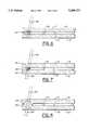
- FIG. 4is an enlarged diagrammatic view in cross-section of a glass panel illustrating the laser-welding method of the present invention
- FIG. 5is a diagrammatic view similar to FIG. 4, but illustrating the completed weld at the edge of the panel according to this invention
- FIG. 6is a diagrammatic view similar to FIG. 4, but illustrating an alternate embodiment, self-regulating method of laser welding according to this invention
- FIG. 7is a diagrammatic view similar to FIG. 6, but illustrating an intermediate phase of the alternate embodiment welding process wherein the absorber material melts and begins to disperse into the melted glass substrate;
- FIG. 8is a view similar to FIG. 7, but illustrating the self-regulating feature of the alternate embodiment where the absorbent material is dispersed enough into the glass substrate such that the laser radiation passes through the glass, instead of being absorbed, to terminate the welding process.
- the glass sheets 12, 14are held apart by glass spacer beads 20, and the edges are sealed vacuum tight by laser welding them.
- a system for making the laser weld 16 around the edges of the glass sheets 12, 14 to seal the vacuum in the space 30is illustrated diagrammatically in FIG. 1. It comprises a thermal vacuum chamber 50 into which the assembly of the glass sheets 12, 14 and spacer beads 20 are positioned.
- the chamber 50is evacuated to the vacuum desired in the space 30, such as 10 -6 torr, and the glass sheets 12, 14 are heated to, or slightly above, their annealing temperature.
- a laser beam 80 from a laser source 72is steered by a mirror 76 to focus on the peripheral edge of the top glass sheet 12 to melt the edge of the top glass sheet 12 together with the edge of the bottom glass sheet 14 to produce a glass weld 16 all around the panel 10.
- the laser beam 80is focused on the edge of the top glass sheet 12 to heat it to its melting temperature and to melt it together with the edge of the bottom glass sheet 14 to create the welded edge seal 16, as shown in FIG. 3.
- the laser beam 80 in the prior art embodimenthad to be radiation of a wavelength that is absorbed by glass, i.e., in the higher infrared range, and it had to be powerful enough to create sufficient heat to melt all the way through the top sheet 12 and into the bottom sheet 14. For example, a CO 2 laser with a wavelength of about 10.6 ⁇ m was suggested for that application.
- FIGS. 4 and 5The improvement of this invention is illustrated in FIGS. 4 and 5.
- a light absorbing material 110such as a metal or an appropriate oxide, is positioned between the glass sheets 12, 14 adjacent the edges where the glass is to be welded.
- the light absorptive heating material 110is preferably highly absorbant of light in wavelengths that are readily transmitted by the glass of sheets 12, 14. Therefore, as shown in FIG. 4, the laser beam 80 can pass unimpeded through the top glass sheet 12 to where it is then absorbed by the light absorbing and heating material 110.
- the laser beam energyUpon being absorbed by the material 110, the laser beam energy is convened and dissipated substantially as heat, which is both conducted and radiated into the adjacent glass panels 12, 14 as indicated by the approximate isothermal lines 112, 114, 116 in FIG. 4.
- the glasscan be, for example, good grade, borosilicate "technical glass", such as Corning 7056 (trademark) manufactured by Corning Glass, of Corning, N.Y., which is substantially transparent or transmissive to light wavelengths in the range of about 0.3 to 2.2 ⁇ m
- the lasercan be, for example, a neodymium doped yttrium aluminum garnet (Nd:YAG), which emits light with wavelength of about 1.06 ⁇ m.
- Nd:YAGneodymium doped yttrium aluminum garnet
- the following glassesare also compatible with Nd:YAG lasers: 1720 aluminosilicate; 0080 soda-lime; 7570 lead silicate; and 7940 fused silica (all available from Corning Glass).
- the light absorptive heating material 110should be substantially absorptive of light in the wavelength range of the laser, and it should be a material that is compatible with the glass.
- a heating material 110 that has a much different coefficient of expansion than the glasscould cause stress fractures in the weld 216 in conditions of large or fast temperature changes.
- the most compatible absorbant material 110is a material that is also soluble in the glass, so it forms a graded, low stress or non-stressed interface with the glass during the welding process.
- Iron oxide (FeO)is a particularly compatible absorbing material for this purpose, because it not only is soluble in glass, but its Fe 2+ ion has its maximum light absorption at a wavelength of about 1.1 ⁇ m, which substantially matches the 1.06 ⁇ m wavelength of the Nd:YAG laser.
- Vanadium ions (V 4+ )which best absorb 1.12 ⁇ m wavelength light
- nickel ions (Ni 2+ )which best absorb light in both the 1.19 ⁇ m and the 1.33 ⁇ m range, are also suitable substitutes.
- a smaller, properly-sized, strip or bead of light absorptive heating material 110such as FeO
- the laser beam 80 with a wavelength that is transmitted by the glass, but absorbed by the material 110is directed through the top glass sheet 12 to the heating material 110.
- the energy from the absorbed laser beam 80emanates from the material 110 as heat into the glass sheets 12, 14, as described above, to melt the glass adjacent the heating material 110.
- the heating material 110dissolves and diffuses into the melted glass to create a zone 130 of concentrated absorbing ions, such as the Fe 2+ ions from the dissolved FeO.
- the concentrated ions and the remaining undissolved material 110still absorb most of the laser beam 80, thus continue to produce enough heat to continue melting the surrounding glass as the weld 216 widens.
- some of the laser beam 80does pass through the zone 130 of concentrated ions.
- the remaining heating material 110becomes entirely dissolved into the surrounding glass. Then, as the dissolved ions diffuse into a widening zone 130', as shown in FIG. 8, they absorb less and less of the laser beam 80 as more and more of the laser beam 80 passes through the zone 130' and bottom glass sheet 14. Eventually, there is insufficient energy absorbed from the laser beam 80 to keep the glass melted, so it solidifies and self-ends or stops the welding process, even if the laser beam 80 is still incident on the zone 130'.
Landscapes
- Chemical & Material Sciences (AREA)
- Engineering & Computer Science (AREA)
- Materials Engineering (AREA)
- Organic Chemistry (AREA)
- Ceramic Engineering (AREA)
- Life Sciences & Earth Sciences (AREA)
- Chemical Kinetics & Catalysis (AREA)
- General Chemical & Material Sciences (AREA)
- Geochemistry & Mineralogy (AREA)
- Civil Engineering (AREA)
- Structural Engineering (AREA)
- Joining Of Glass To Other Materials (AREA)
Abstract
Description
The United States Government has rights in this invention under Contract No. DE-AC36-83CH10093 between the U.S. Department of Energy and the National Renewable Energy Laboratory, a Division of Midwest Research Institute.
1. Field of the Invention
This invention is generally related to laser processing of materials and more specifically to an improved method of welding or sealing together the edges of juxtaposed, spaced apart glass sheets in a vacuum.
2. Description of the Prior Art
In our U.S. Pat. No. 4,683,154, which is incorporated herein by reference, we described a laser sealed vacuum insulation window. The window comprises two juxtaposed sheets of glass held spaced apart in relation to each other by a plurality of spherical glass beads, and the edges of the juxtaposed glass sheets are glass-welded together to provide a sealed, evacuated space between the juxtaposed glass sheets that is completely glass-sealed from the exterior. The edges of the juxtaposed glass sheets are welded together in a vacuum chamber by a laser beam that is focused and steered around the edges of the glass sheets. The laser used to melt and weld the edges together had to be of a wavelength that is absorbed by the glass and of sufficient power to raise the temperature of the glass edges to the melting temperature of the glass, which is about 1,200° C. to 1,300° C. for borosilicate glass.
Unfortunately, the laser welding of the edges of the juxtaposed glass sheets to seal the vacuum space has been hindered by several technical problems that occur when the glass is heated above its annealing temperature in the vacuum chamber. First, dissolved gases in the glass tend to nucleate bubbles in the weld line, which become defects that can produce flaws and failures of the vacuum tight seal. Second, the molten glass at the weld point vaporizes and contaminates the mirror in the vacuum chamber that is used to steer the laser beam around the edges of the glass sheets being welded, which decreases specularity of the mirror and diffuses the laser beam, thus causing a loss of power and frustrating the welding process, and, if allowed to continue, could result in excessive absorption of the laser beam and consequent heat damage to the mirror.
Accordingly, it is a general object of the present invention to improve the process of laser welding/sealing the edges of juxtaposed sheets of glass together in a vacuum.
It is a more specific object of the present invention to provide a method for laser welding sheets of glass together that reduces the tendency to form gas bubbles in the weld.
It is still another specific object of the present invention to provide a method of laser welding glass sheets together in a vacuum that minimizes vapor production at the weld point.
A further object of this invention is to provide a more efficient and controllable method of laser welding glass sheets together.
Additional objects, advantages, and novel features of the invention shall be set forth in part in the description that follows, and in part will become apparent to those skilled in the art upon examination of the following or may be learned by the practice of the invention. The objects and the advantages may be realized and attained by means of the instrumentalities and in combinations particularly pointed out in the appended claims.
To achieve the foregoing and other objects and in accordance with the purposes of the present invention, the method of this invention may comprise the steps of positioning a strip of radiation absorbant material between the edges of two juxtaposed glass sheets that are transparent to the radiation, irradiating the strip of absorbant material through a glass sheet so that it absorbs sufficient energy to emanate enough heat to melt and flow together the portions of the glass sheets that are adjacent the absorbant material, and then allowing the melted glass to cool and solidify to form the welded seal. One embodiment also includes the step of dissolving and diffusing the absorbant material into the melted glass enough so that it does not absorb and emanate enough energy to keep the glass melted, thereby providing self-stopping of the welding.
The accompanying drawings, which are incorporated in and form a part of the specifications, illustrate the preferred embodiments of the present invention, and together with the descriptions serve to explain the principles of the invention.
In the Drawings:
In FIG. 1 is a diagrammatic view of a prior art laser welding system for welding and sealing edges of juxtaposed glass sheets that can be used in the method of the present invention;
FIG. 2 is an enlarged diagrammatic view of a laser-welded edge seal according to the prior art process of which this invention is an improvement;
FIG. 3 is an enlarged diagrammatic view of a laser-welded edge seal according to the prior art process of which this invention is an improvement;
FIG. 4 is an enlarged diagrammatic view in cross-section of a glass panel illustrating the laser-welding method of the present invention;
FIG. 5 is a diagrammatic view similar to FIG. 4, but illustrating the completed weld at the edge of the panel according to this invention;
FIG. 6 is a diagrammatic view similar to FIG. 4, but illustrating an alternate embodiment, self-regulating method of laser welding according to this invention;
FIG. 7 is a diagrammatic view similar to FIG. 6, but illustrating an intermediate phase of the alternate embodiment welding process wherein the absorber material melts and begins to disperse into the melted glass substrate; and
FIG. 8 is a view similar to FIG. 7, but illustrating the self-regulating feature of the alternate embodiment where the absorbent material is dispersed enough into the glass substrate such that the laser radiation passes through the glass, instead of being absorbed, to terminate the welding process.
In our previous embodiment of U.S. Pat. No. 4,683,154, as illustrated in FIG. 2, thelaser beam 80 is focused on the edge of thetop glass sheet 12 to heat it to its melting temperature and to melt it together with the edge of thebottom glass sheet 14 to create thewelded edge seal 16, as shown in FIG. 3. Thelaser beam 80 in the prior art embodiment, as best seen in FIG. 2, had to be radiation of a wavelength that is absorbed by glass, i.e., in the higher infrared range, and it had to be powerful enough to create sufficient heat to melt all the way through thetop sheet 12 and into thebottom sheet 14. For example, a CO2 laser with a wavelength of about 10.6 μm was suggested for that application. The process was difficult to control, because to get enough heat into thebottom glass sheet 14, the adjacent area of the top sheet had to be almost totally melted, thus puddling and sometimes running. Besides being an inefficient use and dissipation of heat, the heat vaporized some of the glass, as illustrated by thearrows 102 in FIG. 2, which vapor migrated to and deposited on thesteering mirror 76 causing diffraction, scattering, and weakening of thelaser beam 80, as well as producing a heat-absorbing surface on the mirror that would, if not checked, raise the temperature of the mirror to damaging levels. Also, glass is a supercooled liquid that has gas bubbles dissolved in it. The high temperatures and power of heat dissipation required to melt all the way through thetop glass sheet 12 and into thebottom glass sheet 14 and the resulting large amount of melt pool created caused substantial amounts of the dissolved gases in the glass to be freed to makebubbles 104. The resultingweld 16, as shown in FIG. 3, had an excess oflarge bubbles 104 formed and then trapped. Such large, trappedbubbles 104 can weaken the integrity of theweld 16, and they often became points of stress concentration and caused fractures and failure of theweld 16 and consequent loss of vacuum from thespace 30.
The improvement of this invention is illustrated in FIGS. 4 and 5. Alight absorbing material 110, such as a metal or an appropriate oxide, is positioned between theglass sheets absorptive heating material 110 is preferably highly absorbant of light in wavelengths that are readily transmitted by the glass ofsheets laser beam 80 can pass unimpeded through thetop glass sheet 12 to where it is then absorbed by the light absorbing andheating material 110. Upon being absorbed by thematerial 110, the laser beam energy is convened and dissipated substantially as heat, which is both conducted and radiated into theadjacent glass panels isothermal lines 112, 114, 116 in FIG. 4. This heat is sufficient to melt theadjacent glass panels surfaces 12', 14', where the weld has to be made, instead of from the outside surface, as was described above and illustrated in FIG. 2. With the heat concentrated more where it is needed, the welding process is more efficient. Less heat is needed for less time to make theweld 216, which forms around the hot, light absorbingmaterial 110, as shown in FIG. 5. Also, by using less and more concentrated heat for less time, formation of gas bubbles is more controlled and minimized, if not eliminated. Anygas bubbles 104 that might form are small and dispersed, as illustrated in FIG. 5, thus not as potentially harmful to theweld 216. It is preferable, although not always necessary, to heat theentire glass sheets mirror 76 is also reduced substantially by the improved method of this invention. Not only does the more confined and lower energy weld process produce less vapor, but thetop glass sheet 12 actually functions as a vapor shield between the weld area and themirror 76 to confinevapor 102, as shown in FIG. 4.
In the embodiment described above and shown in FIGS. 4 and 5, the glass can be, for example, good grade, borosilicate "technical glass", such as Corning 7056 (trademark) manufactured by Corning Glass, of Corning, N.Y., which is substantially transparent or transmissive to light wavelengths in the range of about 0.3 to 2.2 μm, and the laser can be, for example, a neodymium doped yttrium aluminum garnet (Nd:YAG), which emits light with wavelength of about 1.06 μm. However, there are many other glasses and lasers that can fit the transmissive criteria discussed above.
For example, the following glasses are also compatible with Nd:YAG lasers: 1720 aluminosilicate; 0080 soda-lime; 7570 lead silicate; and 7940 fused silica (all available from Corning Glass).
The lightabsorptive heating material 110, therefore, should be substantially absorptive of light in the wavelength range of the laser, and it should be a material that is compatible with the glass. For example, aheating material 110 that has a much different coefficient of expansion than the glass could cause stress fractures in theweld 216 in conditions of large or fast temperature changes.
The most compatibleabsorbant material 110 according to this invention is a material that is also soluble in the glass, so it forms a graded, low stress or non-stressed interface with the glass during the welding process. Iron oxide (FeO) is a particularly compatible absorbing material for this purpose, because it not only is soluble in glass, but its Fe2+ ion has its maximum light absorption at a wavelength of about 1.1 μm, which substantially matches the 1.06 μm wavelength of the Nd:YAG laser. Vanadium ions (V4+), which best absorb 1.12 μm wavelength light, and nickel ions (Ni2+), which best absorb light in both the 1.19 μm and the 1.33 μm range, are also suitable substitutes. These substitutes and many others, such as graphite and Kovar, may be useful, depending on the particular glass transmissivity and laser wavelength combination being used. In fact, the solubility of FeO and other suitable compounds in glass, if used in appropriate proportion with the heat needed to create an effective weld, can yield the additional advantage of a self-regulating or self-stopping welding process. Specifically, as the hot FeO dissolves into the surrounding melted glass, it diffuses into an ever-widening area and eventually becomes too diluted to absorb enough of thelaser beam 80 to keep the glass melted. If such depletion occurs as theweld 216 becomes sufficiently complete to seal thevacuum space 30 between theglass sheets
For example, as shown in FIG. 6, a smaller, properly-sized, strip or bead of lightabsorptive heating material 110, such as FeO, is shown, as before, sandwiched between theglass sheets laser beam 80 with a wavelength that is transmitted by the glass, but absorbed by thematerial 110 is directed through thetop glass sheet 12 to theheating material 110. The energy from the absorbedlaser beam 80 emanates from thematerial 110 as heat into theglass sheets heating material 110.
As the glass melts and flows around theheating material 110, as illustrated in FIG. 7, theheating material 110, dissolves and diffuses into the melted glass to create azone 130 of concentrated absorbing ions, such as the Fe2+ ions from the dissolved FeO. The concentrated ions and the remainingundissolved material 110 still absorb most of thelaser beam 80, thus continue to produce enough heat to continue melting the surrounding glass as theweld 216 widens. However, as shown by the broken line rays 80' in FIG. 7, some of thelaser beam 80 does pass through thezone 130 of concentrated ions.
As the welding progresses, the remainingheating material 110 becomes entirely dissolved into the surrounding glass. Then, as the dissolved ions diffuse into a widening zone 130', as shown in FIG. 8, they absorb less and less of thelaser beam 80 as more and more of thelaser beam 80 passes through the zone 130' andbottom glass sheet 14. Eventually, there is insufficient energy absorbed from thelaser beam 80 to keep the glass melted, so it solidifies and self-ends or stops the welding process, even if thelaser beam 80 is still incident on the zone 130'. Of course, by that time in a welding process, it is time for the laser beam to be moving away to an adjacent area (not shown) where the welding of the edges ofsheets reliable welds 216 can be obtained according to this invention. The resultingweld 216 remains substantially transparent, and the dissolvedheating material 110 becomes substantially invisible except perhaps for some coloration imparted to themolten glass weld 216.
The foregoing description is considered as illustrative only of the principles of the invention. Furthermore, since numerous modifications and changes will readily occur to those skilled in the art, it is not desired to limit the invention to the exact construction and process shown as described above. Accordingly, all suitable modifications and equivalents may be resorted to falling within the scope of the invention as defined by the claims which follow.
Claims (14)
1. A method of welding together two juxtaposed sheets of glass that are transparent to certain radiation, comprising the steps of:
positioning a radiation absorbent and heat dissipating material between said sheets;
directing a beam of said radiation through at least one of said sheets to said material and allowing said material to absorb sufficient amounts of said radiation to produce and emanate sufficient heat to said glass sheets to melt portions of said glass sheets that are adjacent said material;
allowing the melted portions of said adjacent sheets to flow together and then to cool below melting point temperature and solidify to form a weld from the melted portion of said adjacent sheets.
2. The method of claim 1, including the step of dissolving said material into said melted glass.
3. The method of claim 2, including the step of allowing said dissolved material to diffuse into said melted glass to a sufficient extent that the material absorbs insufficient amounts of said radiation to produce enough heat to keep the glass melted.
4. The method of claim 1, wherein said material comprises an oxide.
5. The method of claim 4, wherein said oxide comprises iron oxide (FeO).
6. The method of claim 4, wherein said oxide comprises vanadium oxide (VO2).
7. The method of claim 4, wherein said oxide comprises nickel oxide (NiO).
8. The method of claim 1, wherein said radiation has a wavelength in the range of 0.3 to 2.2 μm.
9. The method of claim 8, wherein said radiation is a laser beam.
10. The method of claim 9, wherein said laser beam is produced by a Nd:YAG laser.
11. The method of claim 3, wherein the material is positioned with respect to the radiation and the glass sheets so as to produce sufficient heat to result in a completed weld fastening said two sheets together with a vacuum-tight seal.
12. A method of welding together and hermetically sealing a space between peripheral edges of two juxtaposed sheets of glass which are substantially transparent to optical energy, comprising the steps of:
positioning a strip of optical energy absorbent and heat dissipating material between the peripheral edges of the respective juxtaposed sheets of glass; and
irradiating said strip of material through at least one of said sheets of glass with enough of said optical energy to produce enough heat in said strip of material to heat, melt, and flow together portions of both of said sheets of glass that are adjacent said strip; and
allowing said melted portions of said sheets of glass to cool, solidify and to hermetically seal to each other.
13. The method of claim 12, including the step of dissolving said strip of material with the melted glass.
14. The method of claim 13, including the step of allowing the dissolved strip of material to diffuse into the melted glass enough to lower absorption of the optical energy enough so that insufficient heat is produced by the remaining absorption to keep the glass melted.
Priority Applications (5)
| Application Number | Priority Date | Filing Date | Title |
|---|---|---|---|
| US08/274,788US5489321A (en) | 1994-07-14 | 1994-07-14 | Welding/sealing glass-enclosed space in a vacuum |
| EP95927268AEP0771313B1 (en) | 1994-07-14 | 1995-07-13 | Welding/sealing glass-enclosed space in a vacuum |
| AU31350/95AAU3135095A (en) | 1994-07-14 | 1995-07-13 | Welding/sealing glass-enclosed space in a vacuum |
| DE69519028TDE69519028T2 (en) | 1994-07-14 | 1995-07-13 | WELDING / MELTING A CAVITY SURROUNDED BY GLASS IN THE VACUUM |
| PCT/US1995/009068WO1996002473A1 (en) | 1994-07-14 | 1995-07-13 | Welding/sealing glass-enclosed space in a vacuum |
Applications Claiming Priority (1)
| Application Number | Priority Date | Filing Date | Title |
|---|---|---|---|
| US08/274,788US5489321A (en) | 1994-07-14 | 1994-07-14 | Welding/sealing glass-enclosed space in a vacuum |
Publications (1)
| Publication Number | Publication Date |
|---|---|
| US5489321Atrue US5489321A (en) | 1996-02-06 |
Family
ID=23049615
Family Applications (1)
| Application Number | Title | Priority Date | Filing Date |
|---|---|---|---|
| US08/274,788Expired - Fee RelatedUS5489321A (en) | 1994-07-14 | 1994-07-14 | Welding/sealing glass-enclosed space in a vacuum |
Country Status (5)
| Country | Link |
|---|---|
| US (1) | US5489321A (en) |
| EP (1) | EP0771313B1 (en) |
| AU (1) | AU3135095A (en) |
| DE (1) | DE69519028T2 (en) |
| WO (1) | WO1996002473A1 (en) |
Cited By (115)
| Publication number | Priority date | Publication date | Assignee | Title |
|---|---|---|---|---|
| US5604642A (en)* | 1995-01-20 | 1997-02-18 | The United States Of America As Represented By The Secretary Of The Air Force | Laser welding of light-weight honeycomb mirrors |
| US5643644A (en)* | 1993-09-27 | 1997-07-01 | Saint Gobain Vitrage | Insulating glazing |
| WO1998026440A1 (en)* | 1996-12-12 | 1998-06-18 | Candescent Technologies Corporation | Gap jumping to seal structure |
| US5820435A (en)* | 1996-12-12 | 1998-10-13 | Candescent Technologies Corporation | Gap jumping to seal structure including tacking of structure |
| US5847356A (en)* | 1996-08-30 | 1998-12-08 | Hewlett-Packard Company | Laser welded inkjet printhead assembly utilizing a combination laser and fiber optic push connect system |
| US6109994A (en)* | 1996-12-12 | 2000-08-29 | Candescent Technologies Corporation | Gap jumping to seal structure, typically using combination of vacuum and non-vacuum environments |
| US6162403A (en)* | 1998-11-02 | 2000-12-19 | General Motors Corporation | Spin formed vacuum bottle catalytic converter |
| US6212852B1 (en)* | 1999-03-15 | 2001-04-10 | Industrial Technology Research Institute | Evacuated glazing containing a thermally insulating vacuum |
| EP1046620A3 (en)* | 1999-04-23 | 2001-05-02 | Institut für Angewandte Photovoltaik | Method for welding material surfaces |
| US6291036B1 (en) | 1999-05-03 | 2001-09-18 | Guardian Industries Corporation | Vacuum IG window unit with spacers in seal |
| US6326067B1 (en) | 1999-05-03 | 2001-12-04 | Guardian Industries Corporation | Vacuum IG pillar with DLC coating |
| US6336984B1 (en) | 1999-09-24 | 2002-01-08 | Guardian Industries Corporation | Vacuum IG window unit with peripheral seal at least partially diffused at temper |
| US6352749B1 (en) | 1999-12-10 | 2002-03-05 | Guardian Industries Corp. | Vacuum IG unit with transparent spacers |
| US6365242B1 (en) | 1999-07-07 | 2002-04-02 | Guardian Industries Corp. | Peripheral seal for vacuum IG window unit |
| US6372312B1 (en) | 2000-02-17 | 2002-04-16 | Guardian Industries Corp. | Vacuum IG unit with micro-sized spacers |
| US20020050153A1 (en)* | 2000-03-01 | 2002-05-02 | Peter Schultz | Method and apparatus for creating a refractive gradient in glass using laser energy |
| US6383580B1 (en) | 1999-11-12 | 2002-05-07 | Guardian Industries Corp. | Vacuum IG window unit with edge mounted pump-out tube |
| US6399169B1 (en) | 1999-07-07 | 2002-06-04 | Guardian Industries Corp. | Vacuum IG window unit with dual peripheral seal |
| US6420002B1 (en) | 1999-08-18 | 2002-07-16 | Guardian Industries Corp. | Vacuum IG unit with spacer/pillar getter |
| US6436492B1 (en) | 1999-11-16 | 2002-08-20 | Guardian Industries Corp. | Vacuum IG window unit with fiber spacers |
| US6444281B1 (en) | 1999-10-13 | 2002-09-03 | Guardian Industries Corp. | Vacuum IG window unit with spacers between first and second edge seals |
| US20020136500A1 (en)* | 2001-03-15 | 2002-09-26 | Gratrix Edward J. | Attachment of optical elements |
| US6497931B1 (en) | 2000-01-11 | 2002-12-24 | Guardian Industries Corp. | Vacuum IG unit with colored spacers |
| US6503583B2 (en) | 1999-11-16 | 2003-01-07 | Guardian Industries Corp. | Vacuum IG window unit with fiber inclusive edge seal |
| US20030006220A1 (en)* | 2001-07-02 | 2003-01-09 | Michael Cummings | Method of ablating an opening in a hard, non-metallic substrate |
| US6506272B1 (en) | 2000-04-04 | 2003-01-14 | Guardian Industries Corp. | Vacuum IG unit with seal for pump-out aperture |
| US6532681B2 (en)* | 1997-08-08 | 2003-03-18 | Dr. Johannes Heidenhain Gmbh | Position measuring system including partial scale elements |
| US6541083B1 (en) | 2000-01-11 | 2003-04-01 | Guardian Industries Corp. | Vacuum IG unit with alkali silicate edge seal and/or spacers |
| US6558494B1 (en) | 1999-09-24 | 2003-05-06 | Guardian Industries Corp. | Vacuum IG window unit with edge seal at least partially diffused at temper and completed via microwave curing, and corresponding method of making the same |
| US6689318B1 (en) | 1995-08-30 | 2004-02-10 | Radiometer Medical A/S | Apparatus for analysis of physiological fluids |
| US20040035086A1 (en)* | 2000-06-14 | 2004-02-26 | Tetsuo Minaai | Glass panel |
| US6701749B2 (en) | 2000-09-27 | 2004-03-09 | Guardian Industries Corp. | Vacuum IG window unit with edge seal at least partially diffused at temper and completed via microwave curing, and corresponding method of making the same |
| US6722937B1 (en) | 2000-07-31 | 2004-04-20 | Candescent Technologies Corporation | Sealing of flat-panel device |
| US20040206953A1 (en)* | 2003-04-16 | 2004-10-21 | Robert Morena | Hermetically sealed glass package and method of fabrication |
| US20040207314A1 (en)* | 2003-04-16 | 2004-10-21 | Aitken Bruce G. | Glass package that is hermetically sealed with a frit and method of fabrication |
| US20050094937A1 (en)* | 2003-11-05 | 2005-05-05 | Nippon Sheet Glass Company Limited | Optical device and method for fabricating the same |
| US6901772B1 (en)* | 1999-08-05 | 2005-06-07 | Patent-Treuhand-Gesellschaft für elektrische Glühlampen mbH | Method for producing a gas discharge lamp |
| US20050151151A1 (en)* | 2003-04-16 | 2005-07-14 | Hawtof Daniel W. | Hermetically sealed package and method of fabrication of a hermetically sealed package |
| US20050174042A1 (en)* | 2004-01-16 | 2005-08-11 | Ryuji Nishikawa | Display panel and method for manufacturing display panel |
| US20050174039A1 (en)* | 2004-01-20 | 2005-08-11 | Ryuji Nishikawa | Display panel and method for manufacturing display panel |
| US20050199599A1 (en)* | 2004-03-09 | 2005-09-15 | Xinghua Li | Method of fabrication of hermetically sealed glass package |
| US6946171B1 (en) | 1999-09-22 | 2005-09-20 | Guardian Industries Corp. | Vacuum IG pillar with lubricating and/or reflective coating |
| US20060103301A1 (en)* | 2004-11-12 | 2006-05-18 | Eastman Kodak Company | Sealing of organic thin-film light-emitting devices |
| US20060130523A1 (en)* | 2004-12-20 | 2006-06-22 | Schroeder Joseph F Iii | Method of making a glass envelope |
| US20060157274A1 (en)* | 2002-03-22 | 2006-07-20 | Stark David H | Wafer-level hermetic micro-device packages |
| US20070128966A1 (en)* | 2005-12-06 | 2007-06-07 | Becken Keith J | Method of encapsulating a display element |
| US20070128967A1 (en)* | 2005-12-06 | 2007-06-07 | Becken Keith J | Method of making a glass envelope |
| US20070158316A1 (en)* | 2006-01-10 | 2007-07-12 | Honeywell International Inc. | System and method for blind laser brazing |
| KR100749417B1 (en) | 2005-06-30 | 2007-08-14 | 삼성에스디아이 주식회사 | Glass-to-glass joining method using laser, vacuum envelope manufactured by the method |
| US20070241085A1 (en)* | 2006-03-27 | 2007-10-18 | Nec Corporation | Laser cutting method, display apparatus manufacturing method, and display apparatus |
| US20080168801A1 (en)* | 2007-01-12 | 2008-07-17 | Paul Stephen Danielson | Method of sealing glass |
| US20090032924A1 (en)* | 2002-03-22 | 2009-02-05 | Stark David H | Hermetically sealed package with window |
| US20090074997A1 (en)* | 2007-09-14 | 2009-03-19 | Electronics Packaging Solutions, Inc. | Insulating glass unit having multi-height internal standoffs and visible decoration |
| US20100034996A1 (en)* | 2008-08-09 | 2010-02-11 | Lawrence Mott | Asymmetrical flexible edge seal for vacuum insulating glass |
| US20100175347A1 (en)* | 2009-01-15 | 2010-07-15 | Bettger Kenneth J | Filament-strung stand-off elements for maintaining pane separation in vacuum insulating glazing units |
| US20100178439A1 (en)* | 2009-01-15 | 2010-07-15 | Eversealed Windows, Inc. | Flexible edge seal for vacuum insulating glazing units |
| US20100186449A1 (en)* | 2003-04-16 | 2010-07-29 | Aitken Bruce G | Hermetically sealed glass package and method of fabrication |
| US20100218556A1 (en)* | 2009-02-27 | 2010-09-02 | Joel Patrick Carberry | Method and apparatus for the joining of low expansion glass |
| US20100251653A1 (en)* | 2007-03-16 | 2010-10-07 | Ball Aerospace & Technologies Corp. | Integrated Multilayer Insulation |
| US20100252698A1 (en)* | 2007-03-16 | 2010-10-07 | Dye Scott A | Integrated multilayer insulation |
| US7832177B2 (en) | 2002-03-22 | 2010-11-16 | Electronics Packaging Solutions, Inc. | Insulated glazing units |
| US20100313876A1 (en)* | 2008-07-09 | 2010-12-16 | Tvp Solar Sa | Vacuum solar thermal panel with a vacuum tight glass-metal sealing |
| US20110014731A1 (en)* | 2009-07-15 | 2011-01-20 | Kelvin Nguyen | Method for sealing a photonic device |
| US20110067448A1 (en)* | 2008-06-11 | 2011-03-24 | Hamamatsu Photonics K.K. | Fusion-bonding process for glass |
| US20110072854A1 (en)* | 2009-09-25 | 2011-03-31 | Hideto Nikkuni | Method for joining members to be joined and joining apparatus used therefor |
| US20110088430A1 (en)* | 2008-06-23 | 2011-04-21 | Hamamatsu Photonics K.K. | Fusion-bonding process for glass |
| US20110100670A1 (en)* | 2009-10-30 | 2011-05-05 | Canon Kabushiki Kaisha | Joined unit of glass base members, airtight envelope, and method for producing glass structural unit |
| US20120131959A1 (en)* | 2009-11-17 | 2012-05-31 | Lg Hausys, Ltd. | Laser sealing device for glass substrates |
| US8198203B2 (en) | 2008-10-20 | 2012-06-12 | Corning Incorporated | Antimony-free glass, antimony-free frit and a glass package that is hermetically sealed with the frit |
| US20120161305A1 (en)* | 2010-12-23 | 2012-06-28 | Medtronic, Inc. | Techniques for bonding substrates using an intermediate layer |
| KR101165566B1 (en) | 2009-11-25 | 2012-07-16 | 하마마츠 포토닉스 가부시키가이샤 | Glass welding method and glass layer fixing method |
| US20130008880A1 (en)* | 2010-03-16 | 2013-01-10 | Aisin Seiki Kabushiki Kaisha | Pulse laser device, transparent member welding method and transparent member welding apparatus |
| US8448468B2 (en) | 2008-06-11 | 2013-05-28 | Corning Incorporated | Mask and method for sealing a glass envelope |
| US20130153551A1 (en)* | 2011-12-15 | 2013-06-20 | Guardian Industries Corp. | Lighting solution for apparatuses for vacuum insulating glass (vig) unit tip-off, and/or associated methods |
| US8666505B2 (en) | 2010-10-26 | 2014-03-04 | Medtronic, Inc. | Wafer-scale package including power source |
| US20140151742A1 (en)* | 2012-11-30 | 2014-06-05 | Corning Incorporated | Glass sealing with transparent materials having transient absorption properties |
| US8950162B2 (en) | 2010-06-02 | 2015-02-10 | Eversealed Windows, Inc. | Multi-pane glass unit having seal with adhesive and hermetic coating layer |
| US9016091B2 (en) | 2009-11-25 | 2015-04-28 | Hamamatsu Photonics K.K. | Glass welding method and glass layer fixing method |
| US9021836B2 (en) | 2009-11-25 | 2015-05-05 | Hamamatsu Photonics K.K. | Glass welding method and glass layer fixing method |
| US9073778B2 (en) | 2009-11-12 | 2015-07-07 | Hamamatsu Photonics K.K. | Glass welding method |
| US9171721B2 (en) | 2010-10-26 | 2015-10-27 | Medtronic, Inc. | Laser assisted direct bonding |
| US9181126B2 (en) | 2008-05-26 | 2015-11-10 | Hamamatsu Photonics K.K. | Glass fusion method |
| US20160005996A1 (en)* | 2013-01-18 | 2016-01-07 | Innolux Corporation | Display apparatus and the sealing method thereof |
| US9236213B2 (en) | 2009-11-25 | 2016-01-12 | Hamamatsu Photonics K.K. | Glass welding method and glass layer fixing method |
| US9233872B2 (en) | 2009-11-25 | 2016-01-12 | Hamamatsu Photonics K.K. | Glass welding method and glass layer fixing method |
| US9328512B2 (en) | 2011-05-05 | 2016-05-03 | Eversealed Windows, Inc. | Method and apparatus for an insulating glazing unit and compliant seal for an insulating glazing unit |
| US9366071B1 (en) | 2014-12-03 | 2016-06-14 | Peter Petit | Low-friction spacer system for vacuum insulated glass |
| US9515286B2 (en) | 2013-05-10 | 2016-12-06 | Corning Incorporated | Laser welding transparent glass sheets using low melting glass or thin absorbing films |
| WO2017040105A1 (en)* | 2015-08-31 | 2017-03-09 | Corning Incorporated | Two-piece enclosure |
| US9701582B2 (en) | 2009-11-25 | 2017-07-11 | Hamamatsu Photonics K.K. | Glass welding method and glass layer fixing method |
| US9784027B2 (en) | 2013-12-31 | 2017-10-10 | Guardian Glass, LLC | Vacuum insulating glass (VIG) unit with metallic peripheral edge seal and/or methods of making the same |
| US9865533B2 (en) | 2014-12-24 | 2018-01-09 | Medtronic, Inc. | Feedthrough assemblies |
| US9887059B2 (en) | 2009-11-25 | 2018-02-06 | Hamamatsu Photonics K.K. | Glass welding method |
| EP2424822B1 (en) | 2009-05-01 | 2018-02-07 | Guardian Glass, LLC | Vacuum insulating glass unit including infrared meltable glass frit, and/or method of making the same |
| US9922790B2 (en) | 2009-11-25 | 2018-03-20 | Hamamatsu Photonics K.K. | Glass welding method |
| US9944452B1 (en) | 2014-12-12 | 2018-04-17 | Ball Aerospace & Technologies Corp. | Multi-layer insulation |
| US9968794B2 (en) | 2014-12-24 | 2018-05-15 | Medtronic, Inc. | Implantable medical device system including feedthrough assembly and method of forming same |
| US10012019B2 (en) | 2013-12-31 | 2018-07-03 | Guardian Glass, LLC | Vacuum insulating glass (VIG) unit with metallic peripheral edge seal and/or methods of making the same |
| US10098589B2 (en) | 2015-12-21 | 2018-10-16 | Medtronic, Inc. | Sealed package and method of forming same |
| US10124559B2 (en) | 2014-12-24 | 2018-11-13 | Medtronic, Inc. | Kinetically limited nano-scale diffusion bond structures and methods |
| US10136535B2 (en) | 2014-12-24 | 2018-11-20 | Medtronic, Inc. | Hermetically-sealed packages including feedthrough assemblies |
| US10145005B2 (en) | 2015-08-19 | 2018-12-04 | Guardian Glass, LLC | Techniques for low temperature direct graphene growth on glass |
| US20190077122A1 (en)* | 2016-03-31 | 2019-03-14 | Panasonic Intellectual Property Management Co., Ltd. | Glass panel unit and building component including the same |
| US10280680B2 (en) | 2013-12-31 | 2019-05-07 | Guardian Glass, LLC | Vacuum insulating glass (VIG) unit with pump-out port sealed using metal solder seal, and/or method of making the same |
| US10457595B2 (en) | 2014-10-31 | 2019-10-29 | Corning Incorporated | Laser welded glass packages |
| US10822864B2 (en) | 2014-02-03 | 2020-11-03 | V-Glass, Inc. | Compliant hermetic seal system for flat glass panel assembly |
| US10913232B2 (en) | 2016-08-30 | 2021-02-09 | Quest Thermal Group LLC | Cellular load-responsive multilayer insulation |
| US20210249627A1 (en)* | 2020-02-10 | 2021-08-12 | Samsung Display Co., Ltd. | Display device and method of fabricating the same |
| US20210408433A1 (en)* | 2020-06-25 | 2021-12-30 | Samsung Display Co., Ltd. | Display device and method of fabricating the same |
| KR20220049010A (en)* | 2019-08-15 | 2022-04-20 | 코닝 인코포레이티드 | Methods of bonding substrates via bonding and separating portions of the bonded substrates, such as making an array of liquid lenses and separating the array into individual liquid lenses. |
| US11426989B2 (en)* | 2016-11-18 | 2022-08-30 | Corning Optical Communications LLC | Laser bonded transparent glass-based articles and methods of making the same |
| US11851358B1 (en)* | 2016-01-14 | 2023-12-26 | Danbury Mission Technologies, Llc | Optical element shaping systems |
| US20240166548A1 (en)* | 2022-11-23 | 2024-05-23 | LuxWall, Inc. | Method of making vacuum insulated panel using laser processing of seal material to change stoichiometry and/or oxidation state(s) |
| US11992894B2 (en) | 2018-02-23 | 2024-05-28 | Corning Incorporated | Method of separating a liquid lens from an array of liquid lenses |
| US12442243B2 (en) | 2023-10-04 | 2025-10-14 | LuxWall, Inc. | Vacuum insulated panel with optimized seal width(s) |
Families Citing this family (22)
| Publication number | Priority date | Publication date | Assignee | Title |
|---|---|---|---|---|
| US5332458A (en)* | 1991-04-29 | 1994-07-26 | Weyerhaeuser Co | Corrugated paperboard strength enhancing process |
| US6131410A (en)* | 1998-03-16 | 2000-10-17 | The Regents Of The University Of California | Vacuum fusion bonding of glass plates |
| US6000243A (en)* | 1998-04-27 | 1999-12-14 | The Regents Of The University Of California | Vacuum pull down method for an enhanced bonding process |
| KR20000017103A (en)* | 1998-08-07 | 2000-03-25 | 신메이와 인더스트리즈,리미티드 | Glass Fusing Method and Device |
| DE10053402B4 (en)* | 2000-10-24 | 2008-04-17 | Institut für Fügetechnik und Werkstoffprüfung GmbH | Process and device for thermal joining of components made of silicate materials, silicate composites and silicate composite materials |
| US8500933B2 (en) | 2007-12-14 | 2013-08-06 | Guardian Industries Corp. | Localized heating of edge seals for a vacuum insulating glass unit, and/or unitized oven for accomplishing the same |
| US8506738B2 (en) | 2007-12-17 | 2013-08-13 | Guardian Industries Corp. | Localized heating via an infrared heat source array of edge seals for a vacuum insulating glass unit, and/or unitized oven with infrared heat source array for accomplishing the same |
| KR101042724B1 (en)* | 2009-12-17 | 2011-06-20 | (주)알가 | Edge sealing device of vacuum glass panel and vacuum glass panel manufacturing method using the same |
| US8802203B2 (en) | 2011-02-22 | 2014-08-12 | Guardian Industries Corp. | Vanadium-based frit materials, and/or methods of making the same |
| US9309146B2 (en) | 2011-02-22 | 2016-04-12 | Guardian Industries Corp. | Vanadium-based frit materials, binders, and/or solvents and methods of making the same |
| US9290408B2 (en) | 2011-02-22 | 2016-03-22 | Guardian Industries Corp. | Vanadium-based frit materials, and/or methods of making the same |
| US9359247B2 (en) | 2011-02-22 | 2016-06-07 | Guardian Industries Corp. | Coefficient of thermal expansion filler for vanadium-based frit materials and/or methods of making and/or using the same |
| US8733128B2 (en) | 2011-02-22 | 2014-05-27 | Guardian Industries Corp. | Materials and/or method of making vacuum insulating glass units including the same |
| US9458052B2 (en) | 2011-02-22 | 2016-10-04 | Guardian Industries Corp. | Coefficient of thermal expansion filler for vanadium-based frit materials and/or methods of making and/or using the same |
| US9822580B2 (en) | 2011-02-22 | 2017-11-21 | Guardian Glass, LLC | Localized heating techniques incorporating tunable infrared element(s) for vacuum insulating glass units, and/or apparatuses for same |
| KR101326938B1 (en)* | 2011-04-13 | 2013-11-11 | 엘지이노텍 주식회사 | Optical member and display device having the same |
| US9988302B2 (en) | 2014-02-04 | 2018-06-05 | Guardian Glass, LLC | Frits for use in vacuum insulating glass (VIG) units, and/or associated methods |
| US9593527B2 (en) | 2014-02-04 | 2017-03-14 | Guardian Industries Corp. | Vacuum insulating glass (VIG) unit with lead-free dual-frit edge seals and/or methods of making the same |
| CN104230155B (en)* | 2014-09-22 | 2017-12-19 | 天津沽上真空玻璃制造股份有限公司 | The edge bonding method of tempering, half tempered vacuum glass |
| DE102015108431B4 (en) | 2015-05-28 | 2018-11-22 | Schott Ag | Container for storing and / or applying a pharmaceutical substance and process for its preparation |
| WO2017075181A1 (en)* | 2015-10-30 | 2017-05-04 | Corning Incorporated | Vacuum insulated glass unit and pumping system and methodology for evacuating the same |
| US12352101B2 (en) | 2022-07-20 | 2025-07-08 | Jeld-Wen, Inc. | Vacuum insulated glazing units and methods for producing the same |
Citations (8)
| Publication number | Priority date | Publication date | Assignee | Title |
|---|---|---|---|---|
| US3217088A (en)* | 1962-11-30 | 1965-11-09 | Owens Illinois Glass Co | Joining glass members and encapsulation of small electrical components |
| US3749562A (en)* | 1969-07-15 | 1973-07-31 | Co Ind Francoise Tubes Electro | Method for making dry reed switches |
| US4142881A (en)* | 1977-06-27 | 1979-03-06 | Louis Raymond M R G | Process for welding glass so that metallic elements pass through the weld bead |
| US4508514A (en)* | 1983-09-19 | 1985-04-02 | Gte Products Corporation | Single-ended metal halide discharge lamp arc gap fabricating process |
| JPS616015A (en)* | 1984-06-18 | 1986-01-11 | Nissan Motor Co Ltd | Structure to prevent clamp falling off of cable fixing device for operation transmission |
| US4683154A (en)* | 1985-08-19 | 1987-07-28 | The United States Of America As Represented By The United States Department Of Energy | Laser sealed vacuum insulation window |
| US4961768A (en)* | 1989-04-20 | 1990-10-09 | Djeu Nicholas I | Methods for bonding optical fibers to wafers |
| US5176788A (en)* | 1991-07-08 | 1993-01-05 | The United States Of America As Represented By The Secretary Of The Navy | Method of joining diamond structures |
Family Cites Families (6)
| Publication number | Priority date | Publication date | Assignee | Title |
|---|---|---|---|---|
| US2032033A (en)* | 1932-09-29 | 1936-02-25 | Gen Aniline Works Inc | Acid triphenylmethane dyestuffs and a process of preparing them |
| US2193393A (en)* | 1937-10-05 | 1940-03-12 | Danner Edward | Heat insulating glass |
| US2398371A (en)* | 1944-01-26 | 1946-04-16 | Thomas S Gerspacher | Window glass |
| US2521048A (en)* | 1945-01-04 | 1950-09-05 | Libbey Owens Ford Glass Co | Method of fabricating glazing units |
| US3222153A (en)* | 1955-01-10 | 1965-12-07 | Libbey Owens Ford Glass Co | Method of producing multiple sheet glazing units |
| EP0042003B1 (en)* | 1979-12-20 | 1985-03-13 | United Technologies Corporation | Method for forming a fusible spacer for plasma display panel |
- 1994
- 1994-07-14USUS08/274,788patent/US5489321A/ennot_activeExpired - Fee Related
- 1995
- 1995-07-13WOPCT/US1995/009068patent/WO1996002473A1/enactiveIP Right Grant
- 1995-07-13DEDE69519028Tpatent/DE69519028T2/ennot_activeExpired - Fee Related
- 1995-07-13EPEP95927268Apatent/EP0771313B1/ennot_activeExpired - Lifetime
- 1995-07-13AUAU31350/95Apatent/AU3135095A/ennot_activeAbandoned
Patent Citations (8)
| Publication number | Priority date | Publication date | Assignee | Title |
|---|---|---|---|---|
| US3217088A (en)* | 1962-11-30 | 1965-11-09 | Owens Illinois Glass Co | Joining glass members and encapsulation of small electrical components |
| US3749562A (en)* | 1969-07-15 | 1973-07-31 | Co Ind Francoise Tubes Electro | Method for making dry reed switches |
| US4142881A (en)* | 1977-06-27 | 1979-03-06 | Louis Raymond M R G | Process for welding glass so that metallic elements pass through the weld bead |
| US4508514A (en)* | 1983-09-19 | 1985-04-02 | Gte Products Corporation | Single-ended metal halide discharge lamp arc gap fabricating process |
| JPS616015A (en)* | 1984-06-18 | 1986-01-11 | Nissan Motor Co Ltd | Structure to prevent clamp falling off of cable fixing device for operation transmission |
| US4683154A (en)* | 1985-08-19 | 1987-07-28 | The United States Of America As Represented By The United States Department Of Energy | Laser sealed vacuum insulation window |
| US4961768A (en)* | 1989-04-20 | 1990-10-09 | Djeu Nicholas I | Methods for bonding optical fibers to wafers |
| US5176788A (en)* | 1991-07-08 | 1993-01-05 | The United States Of America As Represented By The Secretary Of The Navy | Method of joining diamond structures |
Non-Patent Citations (1)
| Title |
|---|
| IBM Technical Disclosure Jul. 1972 Effecting a Hermetic Seal in a Glass System.* |
Cited By (198)
| Publication number | Priority date | Publication date | Assignee | Title |
|---|---|---|---|---|
| US5855638A (en)* | 1993-09-27 | 1999-01-05 | Saint Gobain Vitrage | Process for producing a vacuum in an insulating glazing |
| US5643644A (en)* | 1993-09-27 | 1997-07-01 | Saint Gobain Vitrage | Insulating glazing |
| US5604642A (en)* | 1995-01-20 | 1997-02-18 | The United States Of America As Represented By The Secretary Of The Air Force | Laser welding of light-weight honeycomb mirrors |
| US6689318B1 (en) | 1995-08-30 | 2004-02-10 | Radiometer Medical A/S | Apparatus for analysis of physiological fluids |
| US5847356A (en)* | 1996-08-30 | 1998-12-08 | Hewlett-Packard Company | Laser welded inkjet printhead assembly utilizing a combination laser and fiber optic push connect system |
| US5820435A (en)* | 1996-12-12 | 1998-10-13 | Candescent Technologies Corporation | Gap jumping to seal structure including tacking of structure |
| US6109994A (en)* | 1996-12-12 | 2000-08-29 | Candescent Technologies Corporation | Gap jumping to seal structure, typically using combination of vacuum and non-vacuum environments |
| US6416375B1 (en) | 1996-12-12 | 2002-07-09 | Candescent Technologies Corporation | Sealing of plate structures |
| KR100400185B1 (en)* | 1996-12-12 | 2003-10-01 | 컨데슨트 인터렉추얼 프로퍼티 서비시스 인코포레이티드 | Gap jumping to seal structure |
| EP1826800A3 (en)* | 1996-12-12 | 2009-05-13 | Canon Kabushiki Kaisha | Gap jumping to seal structure |
| WO1998026440A1 (en)* | 1996-12-12 | 1998-06-18 | Candescent Technologies Corporation | Gap jumping to seal structure |
| US6532681B2 (en)* | 1997-08-08 | 2003-03-18 | Dr. Johannes Heidenhain Gmbh | Position measuring system including partial scale elements |
| US6162403A (en)* | 1998-11-02 | 2000-12-19 | General Motors Corporation | Spin formed vacuum bottle catalytic converter |
| US6212852B1 (en)* | 1999-03-15 | 2001-04-10 | Industrial Technology Research Institute | Evacuated glazing containing a thermally insulating vacuum |
| EP1046620A3 (en)* | 1999-04-23 | 2001-05-02 | Institut für Angewandte Photovoltaik | Method for welding material surfaces |
| US6501044B1 (en) | 1999-04-23 | 2002-12-31 | Institut Fur Angewandte Photovoltaik Gmbh | Method for welding the surfaces of materials |
| US6291036B1 (en) | 1999-05-03 | 2001-09-18 | Guardian Industries Corporation | Vacuum IG window unit with spacers in seal |
| US6326067B1 (en) | 1999-05-03 | 2001-12-04 | Guardian Industries Corporation | Vacuum IG pillar with DLC coating |
| US6399169B1 (en) | 1999-07-07 | 2002-06-04 | Guardian Industries Corp. | Vacuum IG window unit with dual peripheral seal |
| US6365242B1 (en) | 1999-07-07 | 2002-04-02 | Guardian Industries Corp. | Peripheral seal for vacuum IG window unit |
| US6901772B1 (en)* | 1999-08-05 | 2005-06-07 | Patent-Treuhand-Gesellschaft für elektrische Glühlampen mbH | Method for producing a gas discharge lamp |
| US6420002B1 (en) | 1999-08-18 | 2002-07-16 | Guardian Industries Corp. | Vacuum IG unit with spacer/pillar getter |
| US6946171B1 (en) | 1999-09-22 | 2005-09-20 | Guardian Industries Corp. | Vacuum IG pillar with lubricating and/or reflective coating |
| US6558494B1 (en) | 1999-09-24 | 2003-05-06 | Guardian Industries Corp. | Vacuum IG window unit with edge seal at least partially diffused at temper and completed via microwave curing, and corresponding method of making the same |
| US6641689B1 (en) | 1999-09-24 | 2003-11-04 | Guardian Industries Corp. | Vacuum IG window unit with peripheral seal at least partially diffused at temper |
| US6336984B1 (en) | 1999-09-24 | 2002-01-08 | Guardian Industries Corporation | Vacuum IG window unit with peripheral seal at least partially diffused at temper |
| US6444281B1 (en) | 1999-10-13 | 2002-09-03 | Guardian Industries Corp. | Vacuum IG window unit with spacers between first and second edge seals |
| US6383580B1 (en) | 1999-11-12 | 2002-05-07 | Guardian Industries Corp. | Vacuum IG window unit with edge mounted pump-out tube |
| US6436492B1 (en) | 1999-11-16 | 2002-08-20 | Guardian Industries Corp. | Vacuum IG window unit with fiber spacers |
| US6503583B2 (en) | 1999-11-16 | 2003-01-07 | Guardian Industries Corp. | Vacuum IG window unit with fiber inclusive edge seal |
| US6352749B1 (en) | 1999-12-10 | 2002-03-05 | Guardian Industries Corp. | Vacuum IG unit with transparent spacers |
| US6541083B1 (en) | 2000-01-11 | 2003-04-01 | Guardian Industries Corp. | Vacuum IG unit with alkali silicate edge seal and/or spacers |
| US6497931B1 (en) | 2000-01-11 | 2002-12-24 | Guardian Industries Corp. | Vacuum IG unit with colored spacers |
| US6372312B1 (en) | 2000-02-17 | 2002-04-16 | Guardian Industries Corp. | Vacuum IG unit with micro-sized spacers |
| US20020050153A1 (en)* | 2000-03-01 | 2002-05-02 | Peter Schultz | Method and apparatus for creating a refractive gradient in glass using laser energy |
| US6506272B1 (en) | 2000-04-04 | 2003-01-14 | Guardian Industries Corp. | Vacuum IG unit with seal for pump-out aperture |
| US7141130B2 (en)* | 2000-06-14 | 2006-11-28 | Nippon Sheet Glass Co., Ltd. | Glass panel |
| US20040035086A1 (en)* | 2000-06-14 | 2004-02-26 | Tetsuo Minaai | Glass panel |
| US7114306B2 (en)* | 2000-06-14 | 2006-10-03 | Nippon Sheet Glass Co., Ltd. | Glass panel |
| US20060207217A1 (en)* | 2000-06-14 | 2006-09-21 | Tetsuo Minaai | Glass panel |
| US7473152B1 (en) | 2000-07-31 | 2009-01-06 | Canon Kabushiki Kaisha | Sealing of flat-panel device |
| US6722937B1 (en) | 2000-07-31 | 2004-04-20 | Candescent Technologies Corporation | Sealing of flat-panel device |
| US6701749B2 (en) | 2000-09-27 | 2004-03-09 | Guardian Industries Corp. | Vacuum IG window unit with edge seal at least partially diffused at temper and completed via microwave curing, and corresponding method of making the same |
| US6820445B2 (en)* | 2001-03-15 | 2004-11-23 | Zygo Corporation | Attachment of optical elements |
| US20020136500A1 (en)* | 2001-03-15 | 2002-09-26 | Gratrix Edward J. | Attachment of optical elements |
| US20030006220A1 (en)* | 2001-07-02 | 2003-01-09 | Michael Cummings | Method of ablating an opening in a hard, non-metallic substrate |
| US6864460B2 (en) | 2001-07-02 | 2005-03-08 | Virtek Laser Systems, Inc. | Method of ablating an opening in a hard, non-metallic substrate |
| US7832177B2 (en) | 2002-03-22 | 2010-11-16 | Electronics Packaging Solutions, Inc. | Insulated glazing units |
| US20060157274A1 (en)* | 2002-03-22 | 2006-07-20 | Stark David H | Wafer-level hermetic micro-device packages |
| US7517712B2 (en) | 2002-03-22 | 2009-04-14 | Electronics Packaging Solutions, Inc. | Wafer-level hermetic micro-device packages |
| US20090032924A1 (en)* | 2002-03-22 | 2009-02-05 | Stark David H | Hermetically sealed package with window |
| US7602121B2 (en) | 2003-04-16 | 2009-10-13 | Corning Incorporated | Glass package that is hermetically sealed with a frit and method of fabrication |
| US20040207314A1 (en)* | 2003-04-16 | 2004-10-21 | Aitken Bruce G. | Glass package that is hermetically sealed with a frit and method of fabrication |
| US20040206953A1 (en)* | 2003-04-16 | 2004-10-21 | Robert Morena | Hermetically sealed glass package and method of fabrication |
| US20060009109A1 (en)* | 2003-04-16 | 2006-01-12 | Aitken Bruce G | Glass package that is hermetically sealed with a frit and method of fabrication |
| US6998776B2 (en) | 2003-04-16 | 2006-02-14 | Corning Incorporated | Glass package that is hermetically sealed with a frit and method of fabrication |
| JP2006524419A (en)* | 2003-04-16 | 2006-10-26 | コーニング インコーポレイテッド | Glass package sealed with frit and manufacturing method thereof |
| US20050151151A1 (en)* | 2003-04-16 | 2005-07-14 | Hawtof Daniel W. | Hermetically sealed package and method of fabrication of a hermetically sealed package |
| US20070007894A1 (en)* | 2003-04-16 | 2007-01-11 | Aitken Bruce G | Glass package that is hermetically sealed with a frit and method of fabrication |
| US8148179B2 (en)* | 2003-04-16 | 2012-04-03 | Corning Incorporated | Hermetically sealed glass package and method of fabrication |
| US8063560B2 (en) | 2003-04-16 | 2011-11-22 | Corning Incorporated | Glass package that is hermetically sealed with a frit and method of fabrication |
| US7344901B2 (en) | 2003-04-16 | 2008-03-18 | Corning Incorporated | Hermetically sealed package and method of fabricating of a hermetically sealed package |
| US20100186449A1 (en)* | 2003-04-16 | 2010-07-29 | Aitken Bruce G | Hermetically sealed glass package and method of fabrication |
| US20050094937A1 (en)* | 2003-11-05 | 2005-05-05 | Nippon Sheet Glass Company Limited | Optical device and method for fabricating the same |
| US20050174042A1 (en)* | 2004-01-16 | 2005-08-11 | Ryuji Nishikawa | Display panel and method for manufacturing display panel |
| US20050174039A1 (en)* | 2004-01-20 | 2005-08-11 | Ryuji Nishikawa | Display panel and method for manufacturing display panel |
| US20050199599A1 (en)* | 2004-03-09 | 2005-09-15 | Xinghua Li | Method of fabrication of hermetically sealed glass package |
| US7393257B2 (en) | 2004-11-12 | 2008-07-01 | Eastman Kodak Company | Sealing of organic thin-film light-emitting devices |
| US20060103301A1 (en)* | 2004-11-12 | 2006-05-18 | Eastman Kodak Company | Sealing of organic thin-film light-emitting devices |
| US20060130523A1 (en)* | 2004-12-20 | 2006-06-22 | Schroeder Joseph F Iii | Method of making a glass envelope |
| US7565817B2 (en)* | 2004-12-20 | 2009-07-28 | Corning Incorporated | Method of making a glass envelope |
| KR100749417B1 (en) | 2005-06-30 | 2007-08-14 | 삼성에스디아이 주식회사 | Glass-to-glass joining method using laser, vacuum envelope manufactured by the method |
| US7537504B2 (en) | 2005-12-06 | 2009-05-26 | Corning Incorporated | Method of encapsulating a display element with frit wall and laser beam |
| US7597603B2 (en) | 2005-12-06 | 2009-10-06 | Corning Incorporated | Method of encapsulating a display element |
| US20070128966A1 (en)* | 2005-12-06 | 2007-06-07 | Becken Keith J | Method of encapsulating a display element |
| US20070128967A1 (en)* | 2005-12-06 | 2007-06-07 | Becken Keith J | Method of making a glass envelope |
| US20070158316A1 (en)* | 2006-01-10 | 2007-07-12 | Honeywell International Inc. | System and method for blind laser brazing |
| US8791387B2 (en)* | 2006-03-27 | 2014-07-29 | Nlt Technologies, Ltd. | Laser cutting method, display apparatus manufacturing method, and display apparatus |
| US20070241085A1 (en)* | 2006-03-27 | 2007-10-18 | Nec Corporation | Laser cutting method, display apparatus manufacturing method, and display apparatus |
| US20080168801A1 (en)* | 2007-01-12 | 2008-07-17 | Paul Stephen Danielson | Method of sealing glass |
| US7954301B2 (en) | 2007-03-16 | 2011-06-07 | Ball Aerospace & Technologies Corp. | Integrated multilayer insulation |
| US8234835B2 (en) | 2007-03-16 | 2012-08-07 | Quest Product Development Corporation | Integrated multilayer insulation |
| US20100251653A1 (en)* | 2007-03-16 | 2010-10-07 | Ball Aerospace & Technologies Corp. | Integrated Multilayer Insulation |
| US20100252698A1 (en)* | 2007-03-16 | 2010-10-07 | Dye Scott A | Integrated multilayer insulation |
| US7989040B2 (en) | 2007-09-14 | 2011-08-02 | Electronics Packaging Solutions, Inc. | Insulating glass unit having multi-height internal standoffs and visible decoration |
| US20090074997A1 (en)* | 2007-09-14 | 2009-03-19 | Electronics Packaging Solutions, Inc. | Insulating glass unit having multi-height internal standoffs and visible decoration |
| US9181126B2 (en) | 2008-05-26 | 2015-11-10 | Hamamatsu Photonics K.K. | Glass fusion method |
| US10322469B2 (en) | 2008-06-11 | 2019-06-18 | Hamamatsu Photonics K.K. | Fusion bonding process for glass |
| US20110067448A1 (en)* | 2008-06-11 | 2011-03-24 | Hamamatsu Photonics K.K. | Fusion-bonding process for glass |
| US8448468B2 (en) | 2008-06-11 | 2013-05-28 | Corning Incorporated | Mask and method for sealing a glass envelope |
| US9399594B2 (en) | 2008-06-11 | 2016-07-26 | Corning Incorporated | Mask and method for sealing a glass envelope |
| US20110088430A1 (en)* | 2008-06-23 | 2011-04-21 | Hamamatsu Photonics K.K. | Fusion-bonding process for glass |
| US9045365B2 (en) | 2008-06-23 | 2015-06-02 | Hamamatsu Photonics K.K. | Fusion-bonding process for glass |
| US20100313876A1 (en)* | 2008-07-09 | 2010-12-16 | Tvp Solar Sa | Vacuum solar thermal panel with a vacuum tight glass-metal sealing |
| US8096296B2 (en)* | 2008-07-09 | 2012-01-17 | Tvp Solar Sa | Vacuum solar thermal panel with a vacuum tight glass-metal sealing |
| US20100034996A1 (en)* | 2008-08-09 | 2010-02-11 | Lawrence Mott | Asymmetrical flexible edge seal for vacuum insulating glass |
| US8283023B2 (en) | 2008-08-09 | 2012-10-09 | Eversealed Windows, Inc. | Asymmetrical flexible edge seal for vacuum insulating glass |
| US8434328B2 (en) | 2008-10-20 | 2013-05-07 | Corning Incorporated | Antimony-free glass, antimony-free frit and a glass package that is hermetically sealed with the frit |
| US8198203B2 (en) | 2008-10-20 | 2012-06-12 | Corning Incorporated | Antimony-free glass, antimony-free frit and a glass package that is hermetically sealed with the frit |
| US20100178439A1 (en)* | 2009-01-15 | 2010-07-15 | Eversealed Windows, Inc. | Flexible edge seal for vacuum insulating glazing units |
| US20100175347A1 (en)* | 2009-01-15 | 2010-07-15 | Bettger Kenneth J | Filament-strung stand-off elements for maintaining pane separation in vacuum insulating glazing units |
| US8329267B2 (en) | 2009-01-15 | 2012-12-11 | Eversealed Windows, Inc. | Flexible edge seal for vacuum insulating glazing units |
| US8512830B2 (en) | 2009-01-15 | 2013-08-20 | Eversealed Windows, Inc. | Filament-strung stand-off elements for maintaining pane separation in vacuum insulating glazing units |
| US8291728B2 (en)* | 2009-02-27 | 2012-10-23 | Corning Incorporated | Method for the joining of low expansion glass |
| US20100218556A1 (en)* | 2009-02-27 | 2010-09-02 | Joel Patrick Carberry | Method and apparatus for the joining of low expansion glass |
| EP2424822B1 (en) | 2009-05-01 | 2018-02-07 | Guardian Glass, LLC | Vacuum insulating glass unit including infrared meltable glass frit, and/or method of making the same |
| US20110014731A1 (en)* | 2009-07-15 | 2011-01-20 | Kelvin Nguyen | Method for sealing a photonic device |
| US20110072854A1 (en)* | 2009-09-25 | 2011-03-31 | Hideto Nikkuni | Method for joining members to be joined and joining apparatus used therefor |
| US10370896B2 (en) | 2009-10-30 | 2019-08-06 | Canon Kabushiki Kaisha | Joined unit of glass base members, and airtight envelope |
| US20110100670A1 (en)* | 2009-10-30 | 2011-05-05 | Canon Kabushiki Kaisha | Joined unit of glass base members, airtight envelope, and method for producing glass structural unit |
| US9073778B2 (en) | 2009-11-12 | 2015-07-07 | Hamamatsu Photonics K.K. | Glass welding method |
| US20120131959A1 (en)* | 2009-11-17 | 2012-05-31 | Lg Hausys, Ltd. | Laser sealing device for glass substrates |
| KR101165566B1 (en) | 2009-11-25 | 2012-07-16 | 하마마츠 포토닉스 가부시키가이샤 | Glass welding method and glass layer fixing method |
| US9227871B2 (en) | 2009-11-25 | 2016-01-05 | Hamamatsu Photonics K.K. | Glass welding method and glass layer fixing method |
| US9701582B2 (en) | 2009-11-25 | 2017-07-11 | Hamamatsu Photonics K.K. | Glass welding method and glass layer fixing method |
| US9016091B2 (en) | 2009-11-25 | 2015-04-28 | Hamamatsu Photonics K.K. | Glass welding method and glass layer fixing method |
| US9021836B2 (en) | 2009-11-25 | 2015-05-05 | Hamamatsu Photonics K.K. | Glass welding method and glass layer fixing method |
| US9887059B2 (en) | 2009-11-25 | 2018-02-06 | Hamamatsu Photonics K.K. | Glass welding method |
| US9922790B2 (en) | 2009-11-25 | 2018-03-20 | Hamamatsu Photonics K.K. | Glass welding method |
| US9233872B2 (en) | 2009-11-25 | 2016-01-12 | Hamamatsu Photonics K.K. | Glass welding method and glass layer fixing method |
| US9236213B2 (en) | 2009-11-25 | 2016-01-12 | Hamamatsu Photonics K.K. | Glass welding method and glass layer fixing method |
| US8959955B2 (en)* | 2010-03-16 | 2015-02-24 | Aisin Seiki Kabushiki Kaisha | Pulse laser device, transparent member welding method and transparent member welding apparatus |
| US20130008880A1 (en)* | 2010-03-16 | 2013-01-10 | Aisin Seiki Kabushiki Kaisha | Pulse laser device, transparent member welding method and transparent member welding apparatus |
| US8950162B2 (en) | 2010-06-02 | 2015-02-10 | Eversealed Windows, Inc. | Multi-pane glass unit having seal with adhesive and hermetic coating layer |
| US8666505B2 (en) | 2010-10-26 | 2014-03-04 | Medtronic, Inc. | Wafer-scale package including power source |
| US9171721B2 (en) | 2010-10-26 | 2015-10-27 | Medtronic, Inc. | Laser assisted direct bonding |
| US9318400B2 (en) | 2010-10-26 | 2016-04-19 | Medtronic, Inc. | Wafer-scale package including power source |
| US9431312B2 (en) | 2010-10-26 | 2016-08-30 | Medtronic, Inc. | Wafer-scale package including power source |
| US9120287B2 (en) | 2010-12-23 | 2015-09-01 | Medtronic, Inc. | Techniques for bonding substrates using an intermediate layer |
| US9688053B2 (en) | 2010-12-23 | 2017-06-27 | Medtronic, Inc. | Devices formed with techniques for bonding substrates using an intermediate layer |
| US20120161305A1 (en)* | 2010-12-23 | 2012-06-28 | Medtronic, Inc. | Techniques for bonding substrates using an intermediate layer |
| US8796109B2 (en)* | 2010-12-23 | 2014-08-05 | Medtronic, Inc. | Techniques for bonding substrates using an intermediate layer |
| US9328512B2 (en) | 2011-05-05 | 2016-05-03 | Eversealed Windows, Inc. | Method and apparatus for an insulating glazing unit and compliant seal for an insulating glazing unit |
| US11035168B2 (en) | 2011-05-05 | 2021-06-15 | Astravac Glass, Inc. | Method and apparatus for an insulating glazing unit and compliant seal for an insulating glazing unit |
| US8742287B2 (en)* | 2011-12-15 | 2014-06-03 | Guardian Industries Corp. | Lighting solution for apparatuses for vacuum insulating glass (VIG) unit tip-off, and/or associated methods |
| US20130153551A1 (en)* | 2011-12-15 | 2013-06-20 | Guardian Industries Corp. | Lighting solution for apparatuses for vacuum insulating glass (vig) unit tip-off, and/or associated methods |
| JP2015505812A (en)* | 2011-12-15 | 2015-02-26 | ガーディアン・インダストリーズ・コーポレーション | Lighting solution and / or associated method for an apparatus for vacuum insulated glass (VIG) unit chip-off |
| JP2017057139A (en)* | 2012-11-30 | 2017-03-23 | コーニング インコーポレイテッド | Glass sealing with transparent material having transient absorption property |
| US9666763B2 (en)* | 2012-11-30 | 2017-05-30 | Corning Incorporated | Glass sealing with transparent materials having transient absorption properties |
| US20140151742A1 (en)* | 2012-11-30 | 2014-06-05 | Corning Incorporated | Glass sealing with transparent materials having transient absorption properties |
| CN105073671B (en)* | 2012-11-30 | 2018-10-16 | 康宁股份有限公司 | The glass capsulation carried out using the transparent material with transient absorption property |
| US10011525B2 (en) | 2012-11-30 | 2018-07-03 | Corning Incorporated | Glass sealing with transparent materials having transient absorption properties |
| CN105073671A (en)* | 2012-11-30 | 2015-11-18 | 康宁股份有限公司 | Glass sealing using transparent materials with transient absorbing properties |
| US9472778B2 (en)* | 2013-01-18 | 2016-10-18 | Innolux Corporation | Display apparatus and the sealing method thereof |
| US20160005996A1 (en)* | 2013-01-18 | 2016-01-07 | Innolux Corporation | Display apparatus and the sealing method thereof |
| US20230329033A1 (en)* | 2013-05-10 | 2023-10-12 | Corning Incorporated | Sealed devices comprising transparent laser weld regions |
| US12268046B2 (en)* | 2013-05-10 | 2025-04-01 | Corning Incorporated | Sealed devices comprising transparent laser weld regions |
| US9515286B2 (en) | 2013-05-10 | 2016-12-06 | Corning Incorporated | Laser welding transparent glass sheets using low melting glass or thin absorbing films |
| US10283731B2 (en) | 2013-05-10 | 2019-05-07 | Corning Incorporated | Laser welding transparent glass sheets using low melting glass or thin absorbing films |
| US11711938B2 (en)* | 2013-05-10 | 2023-07-25 | Corning Incorporated | Sealed devices comprising transparent laser weld regions |
| US9761828B2 (en) | 2013-05-10 | 2017-09-12 | Corning Incorporated | Laser welding transparent glass sheets using low melting glass or thin absorbing films |
| US10069104B2 (en) | 2013-05-10 | 2018-09-04 | Corning Incorporated | Laser welding transparent glass sheets using low melting glass or thin absorbing films |
| US9741963B2 (en) | 2013-05-10 | 2017-08-22 | Corning Incorporated | Sealed devices comprising transparent laser weld regions |
| US20190074476A1 (en)* | 2013-05-10 | 2019-03-07 | Corning Incorporated | Sealed devices comprising transparent laser weld regions |
| US10012019B2 (en) | 2013-12-31 | 2018-07-03 | Guardian Glass, LLC | Vacuum insulating glass (VIG) unit with metallic peripheral edge seal and/or methods of making the same |
| US10683695B2 (en) | 2013-12-31 | 2020-06-16 | Guardian Glass, Llc. | Vacuum insulating glass (VIG) unit with metallic peripheral edge seal and/or methods of making the same |
| US10280680B2 (en) | 2013-12-31 | 2019-05-07 | Guardian Glass, LLC | Vacuum insulating glass (VIG) unit with pump-out port sealed using metal solder seal, and/or method of making the same |
| US9784027B2 (en) | 2013-12-31 | 2017-10-10 | Guardian Glass, LLC | Vacuum insulating glass (VIG) unit with metallic peripheral edge seal and/or methods of making the same |
| US10822864B2 (en) | 2014-02-03 | 2020-11-03 | V-Glass, Inc. | Compliant hermetic seal system for flat glass panel assembly |
| US10858283B2 (en) | 2014-10-31 | 2020-12-08 | Corning Incorporated | Laser welded glass packages |
| US10457595B2 (en) | 2014-10-31 | 2019-10-29 | Corning Incorporated | Laser welded glass packages |
| US9366071B1 (en) | 2014-12-03 | 2016-06-14 | Peter Petit | Low-friction spacer system for vacuum insulated glass |
| US9944452B1 (en) | 2014-12-12 | 2018-04-17 | Ball Aerospace & Technologies Corp. | Multi-layer insulation |
| US10136535B2 (en) | 2014-12-24 | 2018-11-20 | Medtronic, Inc. | Hermetically-sealed packages including feedthrough assemblies |
| US10981355B2 (en) | 2014-12-24 | 2021-04-20 | Medtronic, Inc | Kinetically limited nano-scale diffusion bond structures and methods |
| US10535596B2 (en) | 2014-12-24 | 2020-01-14 | Medtronic, Inc. | Feedthrough assemblies and methods of forming same |
| US9865533B2 (en) | 2014-12-24 | 2018-01-09 | Medtronic, Inc. | Feedthrough assemblies |
| US11950387B2 (en) | 2014-12-24 | 2024-04-02 | Medtronic, Inc. | Methods for forming hermetically-sealed packages including feedthrough assemblies |
| US9968794B2 (en) | 2014-12-24 | 2018-05-15 | Medtronic, Inc. | Implantable medical device system including feedthrough assembly and method of forming same |
| US10813238B2 (en) | 2014-12-24 | 2020-10-20 | Medtronic, Inc. | Hermetically-sealed packages including feedthrough assemblies |
| US10124559B2 (en) | 2014-12-24 | 2018-11-13 | Medtronic, Inc. | Kinetically limited nano-scale diffusion bond structures and methods |
| US10145005B2 (en) | 2015-08-19 | 2018-12-04 | Guardian Glass, LLC | Techniques for low temperature direct graphene growth on glass |
| WO2017040105A1 (en)* | 2015-08-31 | 2017-03-09 | Corning Incorporated | Two-piece enclosure |
| US10765372B2 (en) | 2015-12-21 | 2020-09-08 | Medtronic, Inc. | Sealed package and method of forming same |
| US10098589B2 (en) | 2015-12-21 | 2018-10-16 | Medtronic, Inc. | Sealed package and method of forming same |
| US11419552B2 (en) | 2015-12-21 | 2022-08-23 | Medtronic, Inc. | Sealed package and method of forming same |
| US10420509B2 (en) | 2015-12-21 | 2019-09-24 | Medtronic, Inc. | Sealed package and method of forming same |
| US11744518B2 (en) | 2015-12-21 | 2023-09-05 | Medtronic, Inc. | Sealed package and method of forming same |
| US11851358B1 (en)* | 2016-01-14 | 2023-12-26 | Danbury Mission Technologies, Llc | Optical element shaping systems |
| US20190077122A1 (en)* | 2016-03-31 | 2019-03-14 | Panasonic Intellectual Property Management Co., Ltd. | Glass panel unit and building component including the same |
| US10675844B2 (en)* | 2016-03-31 | 2020-06-09 | Panasonic Intellectual Property Management Co., Ltd. | Glass panel unit and building component including the same |
| US10913232B2 (en) | 2016-08-30 | 2021-02-09 | Quest Thermal Group LLC | Cellular load-responsive multilayer insulation |
| US11426989B2 (en)* | 2016-11-18 | 2022-08-30 | Corning Optical Communications LLC | Laser bonded transparent glass-based articles and methods of making the same |
| US11992894B2 (en) | 2018-02-23 | 2024-05-28 | Corning Incorporated | Method of separating a liquid lens from an array of liquid lenses |
| CN114556163A (en)* | 2019-08-15 | 2022-05-27 | 康宁股份有限公司 | Methods of bonding substrates and separating a portion of the bonded substrates by a bonding portion, such as making liquid lens arrays and separating arrays into individual liquid lenses |
| KR20220049010A (en)* | 2019-08-15 | 2022-04-20 | 코닝 인코포레이티드 | Methods of bonding substrates via bonding and separating portions of the bonded substrates, such as making an array of liquid lenses and separating the array into individual liquid lenses. |
| KR102809239B1 (en) | 2019-08-15 | 2025-05-19 | 코닝 인코포레이티드 | A method of bonding substrates through a bonding member and separating portions of the bonded substrates, such as manufacturing an array of liquid lenses and separating the array into individual liquid lenses. |
| US12116303B2 (en) | 2019-08-15 | 2024-10-15 | Corning Incorporated | Method of bonding substrates and separating a portion of the bonded substrates through the bond, such as to manufacture an array of liquid lenses and separate the array into individual liquid lenses |
| US20210249627A1 (en)* | 2020-02-10 | 2021-08-12 | Samsung Display Co., Ltd. | Display device and method of fabricating the same |
| US11678502B2 (en)* | 2020-02-10 | 2023-06-13 | Samsung Display Co., Ltd. | Display device having improved bonding between display panel and encapsulation substrate and method of fabricating the same |
| US20210408433A1 (en)* | 2020-06-25 | 2021-12-30 | Samsung Display Co., Ltd. | Display device and method of fabricating the same |
| US20240166548A1 (en)* | 2022-11-23 | 2024-05-23 | LuxWall, Inc. | Method of making vacuum insulated panel using laser processing of seal material to change stoichiometry and/or oxidation state(s) |
| US12338677B2 (en)* | 2022-11-23 | 2025-06-24 | LuxWall, Inc. | Method of making vacuum insulated panel using laser processing of seal material to change stoichiometry and/or oxidation state(s) |
| US12365164B2 (en) | 2022-11-23 | 2025-07-22 | LuxWall, Inc. | Method of making vacuum insulated panel with optimized laser beam size |
| US12377640B2 (en) | 2022-11-23 | 2025-08-05 | LuxWall, Inc. | Method of making vacuum insulated panel with optimized laser speed |
| US12409634B2 (en) | 2022-11-23 | 2025-09-09 | LuxWall, Inc. | Vacuum insulated panel with seal for pump-out tube and/or method of making same |
| US12442243B2 (en) | 2023-10-04 | 2025-10-14 | LuxWall, Inc. | Vacuum insulated panel with optimized seal width(s) |
| US12442244B2 (en) | 2023-10-04 | 2025-10-14 | LuxWall, Inc. | Vacuum insulated panel seal density |
Also Published As
| Publication number | Publication date |
|---|---|
| AU3135095A (en) | 1996-02-16 |
| EP0771313A1 (en) | 1997-05-07 |
| DE69519028T2 (en) | 2001-05-17 |
| DE69519028D1 (en) | 2000-11-09 |
| EP0771313B1 (en) | 2000-10-04 |
| EP0771313A4 (en) | 1997-09-24 |
| WO1996002473A1 (en) | 1996-02-01 |
Similar Documents
| Publication | Publication Date | Title |
|---|---|---|
| US5489321A (en) | Welding/sealing glass-enclosed space in a vacuum | |
| US4424435A (en) | Low expansion laser welding arrangement | |
| TWI474990B (en) | Vacuum insulating glass unit including infrared meltable glass frit, and/or method of making the same | |
| KR102114985B1 (en) | Low temperature hermetic sealing via laser | |
| US8616023B2 (en) | Raised features on transparent substrates and related methods | |
| KR101844082B1 (en) | Glass welding method and glass layer fixing method | |
| KR101844078B1 (en) | Glass welding method and glass layer fixing method | |
| DK1117502T4 (en) | Welding method | |
| US3607176A (en) | Method of sealing metal in a vitreous enclosure | |
| KR102118419B1 (en) | Vacuum insulated glass window unit comprising edge seal and/or method for manufacturing same | |
| JP2007182003A (en) | Laser welding method of resin material | |
| JP2003506846A (en) | Gas discharge lamp manufacturing method | |
| JPH01134427A (en) | Liquid crystal display device | |
| JP2550344B2 (en) | Infrared heating single crystal manufacturing equipment | |
| Ratautas et al. | Sphere-to-plate glass welding using picosecond-laser radiation | |
| KR910007070A (en) | Method for suppressing dislocation generation of dendritic silicon web | |
| JPS6163019A (en) | Formation of semiconductor thin film | |
| JP2006198493A (en) | Liquid crystal panel processing apparatus and liquid crystal panel processing method | |
| JPS58211743A (en) | Manufacture of electrochromic display device | |
| JPH0135798B2 (en) | ||
| JPH0347337Y2 (en) | ||
| US11964898B2 (en) | Laser-induced separation of transparent oxide glass | |
| JP2017075064A (en) | Method and apparatus for processing multiple glass | |
| CN116330673A (en) | Laser plastic welding process | |
| JP2558659B2 (en) | Infrared heating single crystal manufacturing equipment |
Legal Events
| Date | Code | Title | Description |
|---|---|---|---|
| AS | Assignment | Owner name:MIDWEST RESEARCH INSTITUTE, MISSOURI Free format text:ASSIGNMENT OF ASSIGNORS INTEREST;ASSIGNORS:TRACY, C. EDWIN;BENSON, DAVID K.;REEL/FRAME:007084/0590 Effective date:19940711 | |
| AS | Assignment | Owner name:DEPARTMENT OF ENERGY, UNITED STATES OF AMERICA, DI Free format text:CONFIRMATORY LICENSE;ASSIGNOR:MIDWEST RESEARCH INSTITUTE;REEL/FRAME:008034/0127 Effective date:19951005 | |
| FPAY | Fee payment | Year of fee payment:4 | |
| REMI | Maintenance fee reminder mailed | ||
| LAPS | Lapse for failure to pay maintenance fees | ||
| FP | Lapsed due to failure to pay maintenance fee | Effective date:20040206 | |
| STCH | Information on status: patent discontinuation | Free format text:PATENT EXPIRED DUE TO NONPAYMENT OF MAINTENANCE FEES UNDER 37 CFR 1.362 |