US5489258A - Multi-position body support - Google Patents
Multi-position body supportDownload PDFInfo
- Publication number
- US5489258A US5489258AUS08/062,069US6206993AUS5489258AUS 5489258 AUS5489258 AUS 5489258AUS 6206993 AUS6206993 AUS 6206993AUS 5489258 AUS5489258 AUS 5489258A
- Authority
- US
- United States
- Prior art keywords
- vertical support
- frame
- support
- supports
- support frame
- Prior art date
- Legal status (The legal status is an assumption and is not a legal conclusion. Google has not performed a legal analysis and makes no representation as to the accuracy of the status listed.)
- Expired - Lifetime
Links
- 210000003127kneeAnatomy0.000claimsabstractdescription63
- 239000006260foamSubstances0.000claimsdescription10
- 210000002414legAnatomy0.000claimsdescription8
- 230000000994depressogenic effectEffects0.000claimsdescription5
- 230000007935neutral effectEffects0.000claims7
- 239000004616structural foamSubstances0.000claims4
- 230000008878couplingEffects0.000claims3
- 238000010168coupling processMethods0.000claims3
- 238000005859coupling reactionMethods0.000claims3
- 230000035939shockEffects0.000abstractdescription51
- 230000009977dual effectEffects0.000abstractdescription8
- 230000003213activating effectEffects0.000description12
- 239000012190activatorSubstances0.000description9
- 125000006850spacer groupChemical group0.000description8
- 239000007789gasSubstances0.000description5
- 208000014825Abnormal muscle toneDiseases0.000description3
- 230000000881depressing effectEffects0.000description3
- 229920001971elastomerPolymers0.000description3
- 238000003466weldingMethods0.000description3
- IJGRMHOSHXDMSA-UHFFFAOYSA-NAtomic nitrogenChemical compoundN#NIJGRMHOSHXDMSA-UHFFFAOYSA-N0.000description2
- 230000008468bone growthEffects0.000description2
- 230000000694effectsEffects0.000description2
- JOYRKODLDBILNP-UHFFFAOYSA-NEthyl urethaneChemical compoundCCOC(N)=OJOYRKODLDBILNP-UHFFFAOYSA-N0.000description1
- 239000004743PolypropyleneSubstances0.000description1
- 230000037396body weightEffects0.000description1
- 230000014461bone developmentEffects0.000description1
- 239000006227byproductSubstances0.000description1
- 206010008129cerebral palsyDiseases0.000description1
- 239000011248coating agentSubstances0.000description1
- 238000000576coating methodMethods0.000description1
- 238000013461designMethods0.000description1
- 239000000806elastomerSubstances0.000description1
- 230000003203everyday effectEffects0.000description1
- 239000000463materialSubstances0.000description1
- 239000002184metalSubstances0.000description1
- 238000000034methodMethods0.000description1
- 238000012986modificationMethods0.000description1
- 230000004048modificationEffects0.000description1
- 229910052757nitrogenInorganic materials0.000description1
- 238000000554physical therapyMethods0.000description1
- -1polypropylenePolymers0.000description1
- 229920001155polypropylenePolymers0.000description1
- 238000003825pressingMethods0.000description1
- 238000005096rolling processMethods0.000description1
- 210000002784stomachAnatomy0.000description1
- 239000002023woodSubstances0.000description1
Images


Classifications
- A—HUMAN NECESSITIES
- A61—MEDICAL OR VETERINARY SCIENCE; HYGIENE
- A61G—TRANSPORT, PERSONAL CONVEYANCES, OR ACCOMMODATION SPECIALLY ADAPTED FOR PATIENTS OR DISABLED PERSONS; OPERATING TABLES OR CHAIRS; CHAIRS FOR DENTISTRY; FUNERAL DEVICES
- A61G5/00—Chairs or personal conveyances specially adapted for patients or disabled persons, e.g. wheelchairs
- A61G5/10—Parts, details or accessories
- A61G5/14—Standing-up or sitting-down aids
- A—HUMAN NECESSITIES
- A61—MEDICAL OR VETERINARY SCIENCE; HYGIENE
- A61G—TRANSPORT, PERSONAL CONVEYANCES, OR ACCOMMODATION SPECIALLY ADAPTED FOR PATIENTS OR DISABLED PERSONS; OPERATING TABLES OR CHAIRS; CHAIRS FOR DENTISTRY; FUNERAL DEVICES
- A61G7/00—Beds specially adapted for nursing; Devices for lifting patients or disabled persons
- A61G7/10—Devices for lifting patients or disabled persons, e.g. special adaptations of hoists thereto
- A61G7/1001—Devices for lifting patients or disabled persons, e.g. special adaptations of hoists thereto specially adapted for specific applications
- A—HUMAN NECESSITIES
- A61—MEDICAL OR VETERINARY SCIENCE; HYGIENE
- A61G—TRANSPORT, PERSONAL CONVEYANCES, OR ACCOMMODATION SPECIALLY ADAPTED FOR PATIENTS OR DISABLED PERSONS; OPERATING TABLES OR CHAIRS; CHAIRS FOR DENTISTRY; FUNERAL DEVICES
- A61G5/00—Chairs or personal conveyances specially adapted for patients or disabled persons, e.g. wheelchairs
- A61G5/10—Parts, details or accessories
- A61G5/1091—Cushions, seats or abduction devices
- A—HUMAN NECESSITIES
- A61—MEDICAL OR VETERINARY SCIENCE; HYGIENE
- A61G—TRANSPORT, PERSONAL CONVEYANCES, OR ACCOMMODATION SPECIALLY ADAPTED FOR PATIENTS OR DISABLED PERSONS; OPERATING TABLES OR CHAIRS; CHAIRS FOR DENTISTRY; FUNERAL DEVICES
- A61G5/00—Chairs or personal conveyances specially adapted for patients or disabled persons, e.g. wheelchairs
- A61G5/10—Parts, details or accessories
- A61G5/1094—Tables, working plates or trays
- A—HUMAN NECESSITIES
- A61—MEDICAL OR VETERINARY SCIENCE; HYGIENE
- A61G—TRANSPORT, PERSONAL CONVEYANCES, OR ACCOMMODATION SPECIALLY ADAPTED FOR PATIENTS OR DISABLED PERSONS; OPERATING TABLES OR CHAIRS; CHAIRS FOR DENTISTRY; FUNERAL DEVICES
- A61G7/00—Beds specially adapted for nursing; Devices for lifting patients or disabled persons
- A61G7/10—Devices for lifting patients or disabled persons, e.g. special adaptations of hoists thereto
- A61G7/1049—Attachment, suspending or supporting means for patients
- A61G7/1051—Flexible harnesses or slings
- A—HUMAN NECESSITIES
- A61—MEDICAL OR VETERINARY SCIENCE; HYGIENE
- A61G—TRANSPORT, PERSONAL CONVEYANCES, OR ACCOMMODATION SPECIALLY ADAPTED FOR PATIENTS OR DISABLED PERSONS; OPERATING TABLES OR CHAIRS; CHAIRS FOR DENTISTRY; FUNERAL DEVICES
- A61G2200/00—Information related to the kind of patient or his position
- A61G2200/30—Specific positions of the patient
- A61G2200/32—Specific positions of the patient lying
- A61G2200/325—Specific positions of the patient lying prone
- A—HUMAN NECESSITIES
- A61—MEDICAL OR VETERINARY SCIENCE; HYGIENE
- A61G—TRANSPORT, PERSONAL CONVEYANCES, OR ACCOMMODATION SPECIALLY ADAPTED FOR PATIENTS OR DISABLED PERSONS; OPERATING TABLES OR CHAIRS; CHAIRS FOR DENTISTRY; FUNERAL DEVICES
- A61G2200/00—Information related to the kind of patient or his position
- A61G2200/30—Specific positions of the patient
- A61G2200/32—Specific positions of the patient lying
- A61G2200/327—Specific positions of the patient lying supine
- A—HUMAN NECESSITIES
- A61—MEDICAL OR VETERINARY SCIENCE; HYGIENE
- A61G—TRANSPORT, PERSONAL CONVEYANCES, OR ACCOMMODATION SPECIALLY ADAPTED FOR PATIENTS OR DISABLED PERSONS; OPERATING TABLES OR CHAIRS; CHAIRS FOR DENTISTRY; FUNERAL DEVICES
- A61G2200/00—Information related to the kind of patient or his position
- A61G2200/30—Specific positions of the patient
- A61G2200/36—Specific positions of the patient standing
- A—HUMAN NECESSITIES
- A61—MEDICAL OR VETERINARY SCIENCE; HYGIENE
- A61G—TRANSPORT, PERSONAL CONVEYANCES, OR ACCOMMODATION SPECIALLY ADAPTED FOR PATIENTS OR DISABLED PERSONS; OPERATING TABLES OR CHAIRS; CHAIRS FOR DENTISTRY; FUNERAL DEVICES
- A61G2200/00—Information related to the kind of patient or his position
- A61G2200/50—Information related to the kind of patient or his position the patient is supported by a specific part of the body
- A61G2200/52—Underarm
- A—HUMAN NECESSITIES
- A61—MEDICAL OR VETERINARY SCIENCE; HYGIENE
- A61G—TRANSPORT, PERSONAL CONVEYANCES, OR ACCOMMODATION SPECIALLY ADAPTED FOR PATIENTS OR DISABLED PERSONS; OPERATING TABLES OR CHAIRS; CHAIRS FOR DENTISTRY; FUNERAL DEVICES
- A61G5/00—Chairs or personal conveyances specially adapted for patients or disabled persons, e.g. wheelchairs
- A—HUMAN NECESSITIES
- A61—MEDICAL OR VETERINARY SCIENCE; HYGIENE
- A61G—TRANSPORT, PERSONAL CONVEYANCES, OR ACCOMMODATION SPECIALLY ADAPTED FOR PATIENTS OR DISABLED PERSONS; OPERATING TABLES OR CHAIRS; CHAIRS FOR DENTISTRY; FUNERAL DEVICES
- A61G7/00—Beds specially adapted for nursing; Devices for lifting patients or disabled persons
- A61G7/10—Devices for lifting patients or disabled persons, e.g. special adaptations of hoists thereto
- A61G7/104—Devices carried or supported by
- A61G7/1046—Mobile bases, e.g. having wheels
- Y—GENERAL TAGGING OF NEW TECHNOLOGICAL DEVELOPMENTS; GENERAL TAGGING OF CROSS-SECTIONAL TECHNOLOGIES SPANNING OVER SEVERAL SECTIONS OF THE IPC; TECHNICAL SUBJECTS COVERED BY FORMER USPC CROSS-REFERENCE ART COLLECTIONS [XRACs] AND DIGESTS
- Y10—TECHNICAL SUBJECTS COVERED BY FORMER USPC
- Y10S—TECHNICAL SUBJECTS COVERED BY FORMER USPC CROSS-REFERENCE ART COLLECTIONS [XRACs] AND DIGESTS
- Y10S297/00—Chairs and seats
- Y10S297/10—Occupant-arising assist
Definitions
- This inventionrelates to physical therapy aids for non-ambulatory patients.
- the inventionrelates to a multi-position stander for supporting a user in either a prone, supine, or vertical position.
- the inability to interact at peer level and the retarded bone growth and the abnormal muscle tonecan be corrected by placing the person in a standing position.
- Standingplaces the person at peer level and the person's weight is carried by her feet, which reduces the abnormal muscle tone, while allowing the person to be in hip and knee extension.
- the weight-bearing effects of standingstimulate bone growth and free the hands for activity and facilitates the user with head righting.
- Standingalso provides a psychological benefit by providing a way for the user to interact and socialize with others at a peer level. Therefore, it is desirable to have a device, such as a stander, which can orient a user in the standing position.
- the supine positionOrients the user anywhere between a generally horizontal position and an almost vertical position.
- the generally horizontal positionaids in transferring the user from a seated or lying position to the stander.
- the prone positionmuch of the user's weight is carried from the user's upper body to the stander, reducing the weight borne by the user's legs.
- the prone positiongenerally allows the user to comfortably work at a desk or other similar types of furniture.
- the userbears much of her body weight by her legs which are supported by the stander.
- the prone standergenerally comprises a base having a tubular support post pivotally mounted to the base. Laterally adjustable chest support, hip support and knee supports are slidably mounted to the support post. A foot platform is slidably mounted to the support post. A telescoping brace connects the front portion of the frame to the support post to provide for changing the angular orientation of the support post with respect to the base over a limited range of movement and in discrete steps.
- Previous standersare unsatisfactory because they require the physical therapist or the care giver to purchase a separate stander for the prone, supine and vertical position. No previous standers provided for a single stander that could position the user in the prone, supine or vertical position. Therefore, to obtain the benefits of the three positions, the physical therapist or the care giver would have to purchase a stander for each position. Requiring a single stander for each of the three positions increases the cost to the physical therapist or the care giver and reduces the convenience to the physical therapist and care giver for using the stander. Furthermore, many of the previous standers only provided for discrete adjustment of the support pads, which prevented the user from obtaining the most comfortable position of the supports.
- the inventionprovides a simple and convenient-to-use stander that can position the user in the prone, supine and vertical position.
- the inventionfurther provides a stander with an adjustable support pad system for the most comfortable positioning of the pads during use of the stander.
- a multi-position body supportcomprises a base frame, vertical support assembly and body support pads.
- the base frameis supported by the floor.
- the vertical support assemblyis pivotally mounted to the base frame and rotates about an axis of rotation which is generally horizontal with respect to the floor.
- the body support padssupport the user of the multiposition body support on the vertical support assembly by a belt or strap system associated with the body support pads for securing the user within the body support pads.
- the adjustable braceextends between the base frame and the vertical support assembly and adjustably supports the vertical support assembly in a number of different positions between a substantially horizontal position and a vertical position with respect to the base frame.
- the vertical support assemblycomprises a pair of parallel support tubes and the body support pads are clamped to the parallel support tubes.
- a knee support frame having a pair of tubesis slidably received on the parallel support tubes.
- a height adjustment framecomprises a pair of tubes which are slidably received on the parallel support tubes.
- the base framehas caster wheels which can independently lock the swivel movement of the wheel about a vertical axis and the rotation of the wheel about a horizontal axis.
- the body support padscomprise foot pads, knee pads, hip pad, trunk pad and a head pad.
- the foot padsare mounted on the vertical support assembly and can rotate about a horizontal axis, rotate about a vertical axis, laterally adjust with respect to the vertical support assembly and are also adjustable toward and away from the axis of rotation of the vertical support with respect to the base.
- the knee padsare mounted to the vertical support assembly and can be adjusted vertically and laterally with respect to the vertical support assembly.
- the knee padscomprise a U-shaped foam member having a belt spanning the ends of the legs of the U-shaped foam member.
- the hip padis mounted to the vertical support assembly and can be adjusted vertically with respect to the vertical support assembly.
- the hip padcomprises a U-shaped foam member having a belt spanning the ends of the legs of the U-shaped foam member.
- the trunk support padis mounted to the vertical support assembly and can be adjusted vertically with respect to the vertical support assembly.
- the trunk support padcomprises a U-shaped foam member having a larger bite portion than the sides which are tapered for an ergonomic fit under the arms of the user.
- a movable tray assemblyis also provided according to the invention for use with the stander.
- the tray assemblyhas a frame with lockable casters for ease of selective movement of the frame on a floor surface and further has a tray pivotably mounted to the frame at a height for use by a user strapped into the stander in a prone position.
- FIG. 1is a perspective view of the multi-position body support according to the invention oriented in the prone position;
- FIG. 2is a perspective view of the multi-position body support according to the invention oriented in the supine position;
- FIG. 3is a perspective view of the multi-position body support according to the invention oriented in the vertical position;
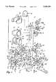
- FIG. 4is an exploded perspective view of the multi-position body support illustrated in FIGS. 1-3 with the padded strapping system not shown for clarity;
- FIG. 5is a front-view of the assembled multi-position body support shown in FIG. 1;
- FIG. 6is a rear view of the assembled multi-position body support shown in FIG. 1;
- FIG. 7is a side view of the assembled multi-position body support shown in FIG. 1 and an auxiliary tray assembly according to the invention
- FIG. 8is a partial sectional, assembly view of the support pads shown in FIG. 4 and showing an alternative belt design
- FIG. 9is a sectional view along line 9--9 of FIG. 5;
- FIG. 10is a sectional view along line 10--10 of FIG. 5;
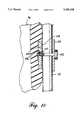
- FIG. 11is a sectional view along line 11--11 of FIG. 6;
- FIG. 12is a rear view of the tray shown in FIG. 7.
- FIGS. 1-4illustrate the multi-position body support 10, commonly known as a stander, in accordance with the invention.
- the multi-position body support 10provides support for a user in an infinite number of positions between a substantially horizontal or lying position to a vertical or standing position, including the either prone (FIG. 1), supine (FIG. 2) or vertical position (FIG. 3).
- the multi-position body supportcan also secure the user lying on her back or lying on her stomach.
- the multi-position body support 10comprises a base frame 12, vertical support assembly 14, body supports 16 and pneumatic shock assembly 17.
- the base frame 12comprises two longitudinal, horizontal, parallel tubular frame members 18, which are rigidly connected near one end by a transverse tubular cross member 20, preferably by welding.
- the tubular frame members 18 and tubular cross member 20define a horizontal plane that is parallel to a floor.
- the ends of the tubular frame members 18are closed by plugs 22.
- Dual lock caster wheels 24are pivotally mounted to each end of the tubular frame members 18 and connect the frame to the floor.
- the caster wheelsare dual lock caster wheels that independently lock both the pivoting of the wheel and the rotation of the wheel.
- a rubber stop 25is mounted to the tubular cross member 20 by a flange 23.
- the base frame 12further comprises aligned, tubular spacers 26.
- Each spaceris mounted to one of the tubular frame members 18 and extends inwardly into the interior of the base frame 12, defining a gap 27 between the tubular spacers 26.
- the end of each tubular spacer 26is closed by a metal plug 28, which has an aperture 30.
- each bushing aperture 30axially aligns with a tubular frame aperture 32 in the tubular frame members 18.
- An axle 34 with threaded axle ends 36, 38is mounted through the aligned plug apertures 30 and tubular frame apertures 32.
- the threaded axle ends 36, 38 of the axle 34receive lock nuts 37, which are covered by a nut cap 39.
- the vertical support assembly 14comprises a vertical support frame 40, knee support frame 42, height adjustment frame 44 and foot position cylinder 84.
- the vertical support frame 40has a horizontal tubular base member 46 whose ends are plugged by bushings 48, which have bushing apertures 50.
- Two identical and parallel support tubes 52are mounted to the tubular base member 46, preferably by welding, and defines the longitudinal axis of the vertical support assembly 14.
- One of the parallel support tubes 52has a plurality of plunger receiving apertures 54 disposed longitudinally along the extent of the parallel support tubes 52 (FIG. 6), preferably on the portion of the tubes facing the tubular cross member 20.
- a tongue 56is mounted to the tubular base member 46, normal to the parallel support tubes 52, preferably by welding, and defines an axis parallel to the longitudinal tubular frame members 18 and perpendicular to the longitudinal axis of the vertical support assembly 14.
- Aligned shock pin apertures 55pass through the parallel support tubes 52.
- the shock pin apertures 55are substantially parallel with and approximately four inches above the tubular base member 46.
- the knee support frame 42comprises connecting tubes 58, which have an inner diameter greater than the outer diameter of the parallel support tubes 52.
- a plunger support 60is mounted near one end of the connecting tubes 58 (FIGS. 6 and 7) and are adapted to receive a support plunger 62, which is biased by a spring (not shown) into the plunger receiving apertures 54.
- Two parallel tubular cross members 64oriented substantially normal to the parallel support tubes 52, are mounted to the connecting tubes 58 by parallel cross member mounting plates 66 and define a lateral or transverse axis for the vertical support assembly 14.
- the cross member mounting plates 66are preferably welded to the connecting tubes 58 and are provided with aligned cross member apertures 68 through which the tubular cross members 64 are inserted.
- the tubular cross members 64are welded to the cross member mounting plates 66.
- the ends of the tubular cross members 64are closed by plugs 70 which are similar to plugs 22.
- the height adjustment frame 44comprises a pair of parallel height adjustment tubes 72 with upper ends 76 and lower ends 80.
- the inner diameter of the height adjustment tubesis greater than the outer diameter of the parallel support tubes 52.
- the height adjustment tubes 72are rigidly connected by a connecting plate 74, preferably at the upper end 76 of the height adjustment tubes 72.
- a plunger support 78is mounted at the lower end 80 of one of the height adjustment tubes 72 (FIGS. 6 and 7) preferably the height adjustment tube 78 disposed above the parallel support tube 52 having the receiving apertures 54, for receiving and supporting a plunger 62.
- Plugs 82similar to plugs 22, close the upper ends of the height adjustment tubes 72.
- the vertical support frame 40is connected to the base frame 12 by positioning the tubular base member 46 within the gap 27 between the tubular spacers 26 and aligning the bushing apertures 50 and 30 to the bushings 48 and plugs 28, respectively, with the tubular frame apertures 32.
- the axle 34is inserted through the aligned tubular frame aperture 32 and bushing apertures 30 and 50.
- the axle 34is positioned so that the threaded axle ends 36 and 38 extend slightly beyond the tubular frame members 18.
- Lock nuts 37are threaded onto the threaded axle ends 36 and 38 to fasten the axle within the base frame 12.
- Nut caps 39are placed over the lock nuts 37.
- the vertical support frame 40can then pivot about the axle 34.
- the angular position of the vertical support framecan be adjusted to any desired position between a horizontal and vertical position.
- the knee support frame 42is slidably mounted onto the parallel support tubes 52 of the vertical support frame 40 by pulling out the spring biased plungers 62 and inserting the parallel support tubes 52 into the connecting tubes 58.
- the knee support frame 42is slidably moved to the desired position and is fixed by releasing the plungers 62 which are then received in plunger receiving apertures 54 of the parallel support tubes 52.
- the plunger 62is pulled out to unlock the knee support frame 42, the knee support frame 42 is repositioned, and the plunger 62 is released.
- the height adjustment frame 44is mounted to the parallel support tubes 52 of the vertical support frame 40.
- the parallel support tubes 52are inserted into the lower ends 80 of the height adjustment tubes 72.
- plungers 62are inserted in the plunger receiving apertures 54 of the parallel support tubes 52 in the same manner as described above for the knee support frame 42.
- the position of the knee support frame 42 and height adjustment frame 44can be independently set by removing the plungers and adjusting either or both the knee support frame and height adjustment frame 44 to a desired position and reinserting the plungers 62.
- the multi-position body support 10can be adjusted for users having a wide range of physical characteristics.
- the foot position cylinder 84is tubular and has opposed horizontally oriented slots 86 and lower slots 91 (FIG. 5) diametrically aligned with upper slots 92.
- the lower slots 91 and upper slots 92extend longitudinally along a substantial portion of the foot positioning cylinder 84.
- An opening 88(FIG. 6) is centrally located on the bottom of the foot position cylinder 84 between the opposed slots 86.
- An off center cam roller 57is mounted within the foot position cylinder 84.
- the off center cam roller 57comprises a bracket 59, which pivotally mounts a roller 61 by an axle 63.
- the axle 63is mounted above the center line of the roller 61 so the roller 61 acts as a camming device.
- An opening 65is defined by the bracket 59 and the roller 61.
- the bracket 59has a threaded opening 67 that aligns with an opening 88 (FIG. 5) disposed below the slot 86 and receives a mounting screw 90 for fixing the position of the foot position cylinder 84 with respect to the tongue 56.
- the foot position cylinder 84is mounted to the tongue 56 by a centrally disposed slot 86, which slidably receives the tongue 56.
- the off center cam roller 57is mounted within the foot position cylinder 84 so that the opening 65 receives the tongue 56 as it passes through the slots 86. As the mounting screw 90 is tightened, the roller 61 cams against the tongue 56 to lock the foot position cylinder 84 with respect to the tongue 56.
- the foot position cylinder 84also has means for rotating the foot supports 102 (described in greater detail later) to provide for variable positioning of the user's feet with respect to the base frame 12.
- the foot supports 102can be rotated at least ⁇ 5 degrees with respect to the plane formed by the tongue 56.
- the foot pad pivoting meanscomprises a generally flat connection plate 69 and a wedge plate 71 having arcuate surfaces 73 and 83, respectively.
- the connection plate 69 and wedge plate 71have apertures 75 and 77, respectively.
- the wedge plate 71is disposed within the interior of the foot position cylinder 84 so that arcuate surface 83 abuts the inner surface of the foot position cylinder 84 and the aperture 77 is accessible through an upper slot 92.
- connection plate 69The arcuate surface 73 of the connection plate 69 is placed on the outer surface of the foot position cylinder 84 so that the apertures 75 and 77 are aligned.
- the mounting screws 90are inserted through the lower slots 91 after placing a washer 79 and a spacer 81 onto the mounting screw 90. The screw is then passed through the aligned apertures 75 and 77 and screwed into the shoe as described below.
- the angular orientation of the foot supports 102are altered by moving the mounting screw 93, connection plate 69 and wedge plate 71 into the desired position and tightening the mounting screw 93 to secure the position of the foot supports 102.
- the spacer 81prevents the threads of the mounting screw 93 from contacting edges of the lower slot 91 and transfers the pressure from the knob 93 to the clamp 71.
- the body supports 16comprise head support 94, trunk support 96, hip support 98, knee supports 100, and foot supports 102. Each support is preferably molded from a structural urethane foam having a soft elastomer coating.
- a mounting plate 104is molded into the trunk support 96.
- the mounting plate 104has a T-nut 106 with a T-nut opening 107 for receiving a mounting screw 132 and at least one other, but smaller, T-nut 115 with opening 113 for receiving a standard Phillips head screw 133 (FIG. 9).
- the T-nuts 106in combination with screw 132 mount the trunk support to the vertical support 14.
- the T-nut 115in combination with Phillips head screw 133 mount the padded strapping system (described in greater detail below) to the trunk support 96.
- the mounting plate 104is preferably made from a wood or wood-by-product material.
- Each of the body supportshave a similar mounting plate 104 with T-nuts as described above.
- the T-nut 115is for mounting a padded strapping system to the body supports as disclosed in FIGS. 5-8 and discussed below.
- the trunk support 96, hip support 98, and knee supports 100are combined with the padded strapping system, which has been removed from FIG. 4 for clarity.
- the foot supports 102also have a mounting plate 104 with a T-nut 106 molded into the foot supports 102.
- the foot supports 102have VelcroTM hook and loop fasteners 112 for securing the user's feet within the foot supports 102. Circular patches of VelcroTM hook and loop patches 117 are bonded to the heel portion of the foot supports 102.
- the VelcroTM hook and loop fasteners 112are attached to the circular VelcroTM hook and loop patches and crossed over the upper surface of the foot supports 102 and wrapped around the bottom of the foot supports 102 where the ends of the VelcroTM hook and loop fasteners are hooked together to fasten the user's foot within the foot supports 102.
- the mounting plates 104 of the foot supportsdo not have T-nuts 115 for mounting the padded strapping system. Otherwise, the mounting plate for the foot support pads are identical to those disclosed above.
- the body supports 16can have a variety of shapes depending on their function and position.
- the head support 94has a plate-like profile.
- the trunk support 96is generally U-shaped and has reduced side portions 114 for a ergonomic fit under the user's arms while leaving the user's arms free (FIG. 7).
- the reduced side portions 114taper to rounded ends 116.
- the hip support 98is generally U-shaped and has side portions of constant width that taper to rounded ends 118.
- the knee supports 100are generally U-shaped and have a pair of opposed side portions 120.
- the side portions 120terminate at rounded ends 118.
- the foot supports 102have a sole portion 124 from which extend upwardly and outwardly opposed side portions 126.
- FIG. 9illustrates the manner in which each of the head support 94, trunk support 96, hip support 98, and knee supports 100 are all connected to the vertical support assembly 14, although FIG. 6 only shows the connection between the trunk support 96 and the vertical support assembly 14.
- the second mounting plate 128further has two arcuate depressions 129 and 131.
- the head support 94, trunk support 96 and hip support 98are mounted to the height adjustment tube 72 of the height adjustment frame 44 by placing the body supports on one side of the height adjustment tubes 72 and the second mounting plate 128 on the opposite side of the height adjustment tubes 72 so that the height adjustment tubes 72 are positioned within the arcuate depressions 129, 131 and the aperture 130 of the second mounting plate 128 is aligned with T-nut 106.
- the mounting screw 132is inserted through the aperture 130 of the second mounting plate 128 and is threaded into the T-nut 106 of the mounting plate 104 of the body supports and tightened.
- the position of the body supportscan be varied by loosening the mounting screw 132 and sliding the body supports and the second mounting plate 128 to the desired position along the height adjustment tubes 72 of the height adjustment frame 44 and re-tightening the mounting screw 132 to fix the position of the body supports.
- the knee supports 100are mounted to the knee support frame 42 by placing the knee supports 100 on one side of the tubular cross member 64 to the outside of the cross member mounting plates 66 and placing the second mounting plate 128 on the opposite side of the tubular cross members 64 so the tubular cross members 64 are positioned within the arcuate depressions 129, 131.
- the mounting screw 132is then inserted through the aperture 130 of the second mounting plate 129 and threaded into the T-nut 106 of the mounting plate 104 on the knee supports 100.
- the lateral position of the knee supports 100can be adjusted by loosening the mounting screw 132 and sliding the knee supports 100 and second mounting plate 128 laterally with respect to the cross member mounting plates 66 and re-tightening the mounting screw 132 when the knee supports 100 are in the desired position.
- the foot supports 102are mounted to the foot position cylinder 84 by passing the mounting screws 93 through upper slots 92 in the foot position cylinder 84 and threading the mounting screws 93 into the T-nut 106 of the mounting plate 104 and the sole portion 124 of the foot supports 102.
- the lateral position of the foot supports 102can be adjusted by loosening the mounting screws 93 and moving the foot supports 102 along the upper slot 92 until the desired position is reached and then tightening the mounting screws 93.
- the longitudinal position of the foot supports 102 with respect to the tongue 56can also be adjusted by loosening the mounting screw 90 and sliding the foot position cylinder 84 along the tongue 56 until the desired position is reached and then tightening the mounting screw 90.
- the foot supports 102are mounted to the vertical support assembly 14 for adjustment toward and away from the axis of rotation between the vertical support assembly 14 at the base frame 12, for adjustment about an axis perpendicular to the axis of rotation between the vertical support assembly 14 and the base frame 12, and for adjustment toward and away from each other and for the rotation about a horizontal axis.
- the trunk support 96has trunk straps 180 and 182 which are mounted to the mounting plate 104.
- FIG. 9illustrates the mounting of trunk strap 182.
- the mounting of all the other straps for the body supportsis similar to the mounting of trunk strap 182.
- the trunk strap 182is mounted to the mounting plate 104 by a phillips head screw 133 that threads into a T-nut 115 after passing through a T-nut opening 113 in the end of the trunk strap 182.
- the trunk straps 180 and 182are divided into two sections: a back section 181, 183 and a front section 185, 187, respectively.
- Snap-fit buckles 111adjustably connect the front sections 185, 187 to the back sections 181, 183, respectively.
- the snap-fit bucklesare enveloped by shoulder pads 189, 191, respectively, which are sewn to the trunk straps 180, 182, respectively.
- the ends of the front sections 185 and 187have VelcroTM hook and eye fasteners attached thereto.
- trunk restraint pads 184 and 186are connected to the trunk straps 180 and 182, respectively. Trunk restraint pads 184 and 186 are mirror images of each other and have a flap portion 188 and 190, respectively, to which is bonded VelcroTM hook and loop fasteners 192 and 194, respectively.
- the hip support 98is combined with a hip restraint pad 208, which has Y-shaped hip straps 196 and 198.
- the Y-shaped hip straps 196 and 198have a split or V-portion 200 and 202, respectively, which converge to a stem portion 204 and 206, respectively.
- the stem portions 204, 206 of the Y-shaped hip straps 196, 198are connected by snap-fit buckles 111 to the web straps 207, 209 of the hip support 98.
- the web straps 207, 209are connected to the hip support 98 by T-nuts and screws in the same manner as described above for the trunk support 96.
- Two sets of D-rings 210 and 212are connected to the hip restraint pads 208 by webs 216 and 218, respectively, which are bonded to the hip restraint pad 208.
- the ends of trunk strap front sections 185 and 187are adapted to be received within the D-rings 210 and 212, respectively, and secured by the VelcroTM hook and eye fasteners.
- the knee supports 100are combined with knee restraint pads 238, which have a pair of Y-shaped straps 222 and 224.
- the Y-shaped straps 222, 224have split portions 226 and 228, respectively, that converge to stem portions 230 and 232, respectively.
- the stem portions 230, 232are connected to web straps 239, 241 of the knee supports 100.
- the web straps 239, 241are connected to the mounting plate 104 by T-nuts and Phillips head screws in the same manner as described above for the trunk support 96.
- the split portions 226, 228are connected to the knee restraint pads 238 by snap-fit buckles 111 connect the stem portions 230, 232 to the web straps 239, 241 to connect the knee restraint pads 100 to the knee supports 100.
- the trunk straps 180 and 182 of the trunk support 96are placed over the user's shoulder and the shoulder pads 189, 191 are adjusted on the trunk straps 180 and 182 so the snap-fit buckles 111 do not directly contact the user's shoulder.
- the trunk restraint pads 184 and 186are positioned in abutting relationship with respect to the user's body and connected to each other by the VelcroTM hook and loop fasteners 192 and 194.
- the flap portion 190By fastening the VelcroTM hook and loop fasteners 192 and 194, the flap portion 190 overlies the flap portion 188 and the trunk straps 180 and 182 are connected horizontally through the VelcroTM hook and loop fastened trunk restraint pads 184 and 186.
- the hip restraint pad 208is then positioned against the user's body opposite the hip support 98 and fastened by connecting the snap-fit buckle 111 to securely fasten the user between the hip support 98 and the hip restraint pad 208.
- the ends of the trunk straps 180 and 182are then inserted into the D-rings 210 and 212 and adjusted before fastening by the VelcroTM hook and loop fasteners.
- the combination of the trunk straps 180 and 182 connected to the hip restraint pad 208 and to each other by the trunk restraint pads 184 and 186effectively creates a harness to restrain the user within the trunk support 96 and the hip support 98.
- the knee restraint pad 238is placed against the user's knee on the opposite side of the knee support 100 and connected to the knee support 100 by fastening the snap-fit buckles 111 and adjusting the stem portions 230, 232 with respect to the snap-fit buckles 111 to draw the knee restraint pad 238 snugly against the user's knee.
- the strapping system as described abovesecurely restrains the user within the trunk support 96, hip support 98 and the knee supports 100 without direct contact between the straps and the user's body.
- the pneumatic shock assembly 17comprises a pneumatic cylinder or shock 134, which is preferably a nitrogen filled gas shock.
- the pneumatic shock 134is well known and can be purchased from Suspa Compart AG in Altdorf, Germany.
- the pneumatic shock 134is connected between the base frame 12 and the vertical support assembly 14 and controls and locks the angular orientation of the vertical support assembly 14 with respect to the base frame 12.
- the pneumatic cylinder or shock 134has a spring shaft 136 which extends outwardly from the cylinder and terminates at a shock ring 138 having an aperture 140.
- the other end of the pneumatic cylinder or shock 134has a tubular threaded extension 135.
- a mushroom-shaped activating pin 145is connected to the pneumatic cylinder or shock 134 and extends through the tubular threaded extension 135.
- a threaded pin connector 142has a diametrically oriented threaded aperture 143 into which the tubular threaded extension is threaded.
- the mushroom-shaped activating pin 145extends through the threaded pin connector 142 via the threaded aperture 143.
- a lock nut 137secures the threaded pin connector 142 to the tubular threaded extension.
- Pressing on the mushroom-shaped activating pin 145unlocks the pneumatic cylinder or shock 134 so the pressurized gas urges the spring shaft 136 outwardly.
- the spring shaft 136is thus biased outwardly of the cylinder by gas within the cylinder and is locked into an adjusted position when the mushroom-shaped activating pin 145 is in the extended position.
- the spring shaft 136can be retracted by depressing the mushroom-shaped activating pin 145 and rotating the vertical support assembly to the position shown in FIG. 2 against the pressure of the gas in the cylinder.
- a mechanical locking, telescoping tube assemblycan be used in lieu of a gas cylinder.
- a foot pedal 146 for actuating the mushroom-shaped activating pin 145 to lock and unlock the pneumatic cylinder or shock 134has a foot plate 147 from which extends a beam 148 with an aperture 150 and terminating in an actuator 152.
- a shock pin activator 166separates the actuator 152 of the foot pedal 146 and the mushroom-shaped activating pin 145 of the pneumatic cylinder or shock 134.
- the shock pin activator 166has a curved radius portion 170 and an aperture 168.
- the pneumatic shock assembly 17is connected at one end to the tubular cross member 20 of the base frame 12 by the flanges 154, which are preferably welded to the tubular cross member 20.
- the flanges 154have pin connector aperture 156, pedal aperture 158 and shock pin aperture 160.
- the threaded pin connector 142is positioned between the flanges 154 and aligned with the pin connector apertures 156.
- Opposed snap rings(not shown) connect the threaded pin connector 142 to the flange 154.
- the foot pedal 146is connected to the flanges 154 by a bolt 164 passing through the pedal apertures 158 and the aperture 150 of the foot pedal 146.
- the actuator 152 of the foot pedal 146is connected to the mushroom-shaped activating pin of the pneumatic cylinder or shock 134 by the curved or radius portion 170 of the shock pin activator.
- the shock pin activator 166is mounted to the flanges 154 by passing a threaded bolt 172 through the threaded shock pin aperture 160 and the aperture 168 of the shock pin activator 166.
- a mounting pin 162is mounted to the flanges 154 to support one end of the curved or radius portion 170 of the shock pin activator 166.
- the pneumatic shock assembly 17is connected to the vertical support frame 40 by the spring shaft 136 of the pneumatic cylinder or shock 134, which is pivotally connected to the height adjustment tubes 72 of the vertical support frame 40.
- Shock pin bushings 174 having apertures 176are positioned on opposite sides of the shock ring 138.
- the shock pin bushings 174 and the shock ring 138are positioned between the parallel support tubes 52 so that the apertures 140, 176 align with the shock pin apertures 55 of the parallel support tubes 52.
- a shock pin 178is inserted through the aligned apertures to pivotally mount the spring shaft 136 to the vertical support frame 40.
- the foot pedal 146can be biased by a torsion spring 159 (FIG. 11) or other similar device so that the foot plate 147 is urged upwardly and almost normal to the horizontal plane of the base frame 12.
- a torsion spring 159FIG. 11
- the curved or radius portion of the shock pin activator 166is preferably curved along the arc which the mushroom-shaped activating pin 145 of the pneumatic cylinder or shock 134 traverses as the pneumatic cylinder or shock 134 is rotated about the mounting pin 162 during the raising and lowering of the vertical support assembly 14 with respect to the base frame 12.
- the actuator 152 of the foot pedalbears against the curved or radius portion 170 of the shock pin activator 166 when the foot pedal 146 is depressed and rotated about the bolt 164.
- the actuator 152can actuate the mushroom-shaped activating pin 145 and unlock the pneumatic cylinder or shock 134 by acting against the curved or radius portion 170 of the shock pin activator 166, which, in turn, depresses the mushroom-shaped activating pin 145 to unlock the pneumatic cylinder or shock 134.
- the useris then transferred from the chair or bed into the body supports 16 of the multi-position body support 10. If the user is to be placed in the prone orientation, the foot supports 102 are rotated on the foot position cylinder 84 so that they face the pneumatic shock assembly 17 and the head support 94 is removed or not mounted to the vertical support assembly 14. However, if the user is to be placed in the supine orientation, the foot supports 102 are pivoted on the foot position cylinder 84 so they face away from the pneumatic shock assembly 17 and the head support 94 is mounted to the height adjustment frame 44 as described above to support the back of the user's head. The trunk support 96, hip support 98 and knee supports 100 are mounted to the vertical support assembly 14 regardless of the prone or supine orientation of the user.
- the relative positions of the body supports 16are initially positioned in the manner described above by measuring the user and adjusting the supports to match the body dimensions of the user. After the user is transferred to the multi-position body support 10 and placed within the body supports 16, final adjustments to the positions of the body supports 16 are independently made in the manner previously described.
- the initial or approximate positioningis first accomplished by moving the knee support frame 42 and height adjustment frame 44 with respect to the parallel support tube 52.
- the final or fine adjustmentsare made by moving the body supports 16.
- the multi-position body supportcan be very accurately adjusted to each individual, providing the user with the greatest amount of comfort.
- the useris then secured to the body supports by fastening the padded strapping system of the trunk support 96, hip support 98, and knee supports 100 and the VelcroTM hook and loop fasteners 112 for the foot supports 102 in either of the methods previously described.
- the operatorcan position the user at any angular orientation with respect to the plane of the base frame 12 from a substantially horizontal or lying position to a substantially vertical or standing position.
- the angular orientationcan vary between 15° to 90° with respect to the base frame 12.
- the body supports 16, especially the trunk support 96are positioned to support the user at any position in the possible range so that the user has uninhibited use of her arms as shown by the dashed lines in FIGS. 5 and 7.
- the operatorgrasps the vertical support assembly 14 and depresses the foot pedal 146 to unlock the pneumatic cylinder or shock 134. While the pedal is depressed, the operator urges the vertical support assembly 14 to the desired position with the aid of the pneumatic cylinder or shock 134.
- the angular positioning of the useris infinite within the range of movement from the lying position to the standing position because the vertical support assembly 14 can be moved to any point between the lying position and the horizontal position, not just at discrete points.
- the multi-position body support 10increases the comfort of the user and utility to the operator by the accurate positioning. Further, the adjustment is made very easily by simply depressing the foot pedal and guiding the vertical support assembly to its adjusted position.
- the angular and lateral position of the user's feet mounted within the foot supports 102can be altered in the manner previously described.
- the lateral position of the user's kneescan also be altered in the manner previously described.
- the usercan be moved to the desired area by rolling the multi-position body support 10 on the dual lock caster wheels 24. Once the multi-position body support 10 is in the desired location, the pivoting and rotation of the dual lock caster wheels 24 can be locked.
- the multi-position body support 10 holding a useris often located near a work surface so that the user can work or engage in every day tasks.
- the multi-position body support 10can be used in combination with a variety of other furniture pieces, such as the wheeled tray 300 shown in FIGS. 6 and 10.
- the wheeled tray 300comprises a tubular base 302, vertical positioning assembly 304, and table top 306.
- the tubular base 302further comprises parallel tubular members rigidly connected by a tubular cross member 310, which is preferably welded to the tubular members 308.
- Caster wheels 312are mounted at each end of the tubular members 308 and preferably are dual locking caster wheels similar to dual lock caster wheels 24.
- the vertical positioning assembly 304comprises parallel support tubes 314, which are welded to the tubular cross member 310 and have a plurality of plunger receiving apertures 316.
- a pair of parallel positioning tubes 318 having an inner diameter greater than the outer diameter of the parallel support tubes 314 and upper end 322 and lower end 320are slidably mounted over the parallel support tubes 314 at their lower ends 320.
- the upper end 322 of the parallel positioning tubes 318are pivotally mounted to the table top 306 by an adjustment means (not shown), which adjusts the angle of the table top 306 with respect to the parallel positioning tubes 318.
- the parallel positioning tubes 318have a spring biased plunger support 324 for receiving and supporting a plunger 326.
- the plunger support 324has a plunger aperture 328, which receives plungers 326.
- the vertical position of the table top 306can be adjusted by sliding the parallel positioning tubes 318 along the parallel support tubes 314 until the desired height is reached.
- the plungers 326are then inserted into the plunger supports 324 and through the plunger aperture 328 into the plunger receiving apertures 316 in the parallel support tubes 314 to fix the vertical position of the table top 306.
- the angle of the table top 306 with respect to the parallel positioning tubes 318is then adjusted by the adjustment means.
- the wheeled tray 300can be used in combination with the multi-purpose body support as shown by the phantom lines in FIG. 7.
- the distance between the tubular members 308 of the tubular base 302is greater than the distance between the outer sides of the tubular frame members 18 so that the wheeled table can be rolled into the desired position close to the user secured in the multi-position body support 10.
- the caster wheels 312can be locked to retain the wheeled tray in the desired position.
- the position of the table topcan be adjusted before or after the wheeled tray is rolled into the desired position in the manner described above.
- the inventionprovides a sturdy body support or stander which can be easily and quickly adjusted to fit different sized users.
- the standercan support the user in a supine, prone, or vertical position in any orientation between horizontal and vertical position.
- the angular orientationis easily adjustable by simply grasping the vertical support assembly, depressing the foot pedal 146 and adjusting the vertical support assembly to a proper height.
- the inventionfurther provides a frame which is ambulatory for ease of movement of the user, yet which is securely lockable in a given location.
- the inventionprovides a combination stander and tray which are moveable with respect to each other for a variety of functions.
Landscapes
- Health & Medical Sciences (AREA)
- Life Sciences & Earth Sciences (AREA)
- Animal Behavior & Ethology (AREA)
- General Health & Medical Sciences (AREA)
- Public Health (AREA)
- Veterinary Medicine (AREA)
- Nursing (AREA)
- Orthopedics, Nursing, And Contraception (AREA)
Abstract
Description
Claims (50)
Priority Applications (1)
| Application Number | Priority Date | Filing Date | Title |
|---|---|---|---|
| US08/062,069US5489258A (en) | 1993-05-14 | 1993-05-14 | Multi-position body support |
Applications Claiming Priority (1)
| Application Number | Priority Date | Filing Date | Title |
|---|---|---|---|
| US08/062,069US5489258A (en) | 1993-05-14 | 1993-05-14 | Multi-position body support |
Publications (1)
| Publication Number | Publication Date |
|---|---|
| US5489258Atrue US5489258A (en) | 1996-02-06 |
Family
ID=22040025
Family Applications (1)
| Application Number | Title | Priority Date | Filing Date |
|---|---|---|---|
| US08/062,069Expired - LifetimeUS5489258A (en) | 1993-05-14 | 1993-05-14 | Multi-position body support |
Country Status (1)
| Country | Link |
|---|---|
| US (1) | US5489258A (en) |
Cited By (60)
| Publication number | Priority date | Publication date | Assignee | Title |
|---|---|---|---|---|
| US5618055A (en)* | 1995-04-21 | 1997-04-08 | Mulholland Designs, Inc. | Stander |
| US5884935A (en)* | 1997-06-09 | 1999-03-23 | Tholkes; Alan L. | Modular standing support |
| US6217057B1 (en)* | 1997-10-02 | 2001-04-17 | Macomb Intermediate School District | Adjustable mobile orthosis seat appliance |
| US6270101B1 (en)* | 1997-11-21 | 2001-08-07 | Marec Hase | Mobile standing device for use in rehabilitation |
| US6308981B1 (en)* | 1998-07-13 | 2001-10-30 | Sisbro, Llc | Transfer lift |
| FR2825616A1 (en)* | 2001-06-12 | 2002-12-13 | Edouard Juszkiewicz | Trolley for moving and lifting a person with reduced mobility has H-shaped base with wheels and detachable upright for tilting support |
| US6601869B2 (en)* | 2000-09-07 | 2003-08-05 | Idc Medical | Body support device for a stand-up wheelchair and wheelchair for said device |
| US6622324B2 (en)* | 2000-03-28 | 2003-09-23 | Hill-Rom Services, Inc. | Hip brace apparatus |
| US20040039320A1 (en)* | 2002-08-22 | 2004-02-26 | Cleveland Michael D. | Spica chair |
| WO2004056302A1 (en)* | 2002-12-19 | 2004-07-08 | Dalen Ylva | Human body supporting device |
| US20040256899A1 (en)* | 2001-12-14 | 2004-12-23 | Stuart Moore | Torso support structures |
| US20050125898A1 (en)* | 2003-12-12 | 2005-06-16 | Leonard Lieboff | Spica cast gurney |
| US7036512B2 (en) | 2003-06-25 | 2006-05-02 | Prodije 9061-7457 Quebec Inc. | Dismountable multi-position stander |
| US20060090258A1 (en)* | 2004-11-01 | 2006-05-04 | Stryker Martin W | Patient transfer device |
| US20060097557A1 (en)* | 2004-10-12 | 2006-05-11 | Tholkes Alan L | Modular standing frame |
| US20060248650A1 (en)* | 2004-11-10 | 2006-11-09 | Skripps Thomas K | Body support apparatus for spinal surgery |
| US20070142760A1 (en)* | 2004-03-26 | 2007-06-21 | Mitchell John R | System and method for correcting clubfoot problems in children |
| US7267657B1 (en)* | 2004-03-26 | 2007-09-11 | Mitchell John R | System and method for correcting club foot problems in children |
| US7523993B1 (en)* | 2007-11-23 | 2009-04-28 | Nova Bus, Division De Groupe Volvo Canada Inc. | Passenger dorsal support |
| US20090146389A1 (en)* | 2005-03-30 | 2009-06-11 | Jaimie Borisoff | Wheelchair |
| US20090186747A1 (en)* | 2008-01-22 | 2009-07-23 | Invacare Corporation | Seat |
| US20090255057A1 (en)* | 2008-04-08 | 2009-10-15 | Stryker Corporation | Patient repositioning system |
| KR100921970B1 (en)* | 2009-01-09 | 2009-10-19 | 김병일 | bathchair |
| US20100007180A1 (en)* | 2008-07-08 | 2010-01-14 | Invacare Corporation | Standing Frame with Supine Mode |
| US20100115757A1 (en)* | 2007-01-31 | 2010-05-13 | Bernhard Sacherer | Device and method for producing an orthopaedic aid, and corresponding aids |
| US20100192300A1 (en)* | 2008-10-28 | 2010-08-05 | Tannoury Tony Y | Prone and laterally angled surgical device and method |
| US20100219668A1 (en)* | 2006-05-12 | 2010-09-02 | Liftseat Corporation | Devices and Methods for Lift Assistance |
| US20100237215A1 (en)* | 2009-03-19 | 2010-09-23 | Glenn Dahl | Patient support |
| US20100287698A1 (en)* | 2009-05-13 | 2010-11-18 | Stryker Corporation | Transport apparatus |
| US20100293713A1 (en)* | 2009-04-01 | 2010-11-25 | Lewis Sharps | Patient-rotation system with center-of- gravity assembly |
| US20110083273A1 (en)* | 2009-04-01 | 2011-04-14 | Patient Safety Transport Systems, Llc | Apparatuses For Posterior Surgery |
| US20110119829A1 (en)* | 2007-08-24 | 2011-05-26 | ALLEN MEDICAL SYSTEMS ,INC. a corporation | Surgical table accessory platform |
| USD645967S1 (en)* | 2010-10-14 | 2011-09-27 | Patient Safety Transport Systems, Llc | Patient-support frame |
| US20120056066A1 (en)* | 2009-05-15 | 2012-03-08 | Habdank Pv-Montagesysteme Gmbh & Co. Kg | Support arrangement for solar modules |
| US20120133113A1 (en)* | 2009-06-01 | 2012-05-31 | Tmsuk Co., Ltd. | Transfer and locomotion apparatus |
| USD663427S1 (en) | 2010-10-14 | 2012-07-10 | Operating Room Safety Enterprises, LLC | Torso-support apparatus |
| US8522907B1 (en)* | 2009-05-12 | 2013-09-03 | Jgi Holdings, Llc | Personal mobility device |
| US20130292196A1 (en)* | 2011-07-27 | 2013-11-07 | Tanren Co., Ltd. | Traveling device |
| US8783403B1 (en) | 2013-01-08 | 2014-07-22 | Llyod L. Robbins | Transfer accessible vehicle for disabled person |
| USD720076S1 (en) | 2013-03-06 | 2014-12-23 | Operating Room Safety Enterprises, LLC | Surgical table |
| US9161875B2 (en) | 2012-09-07 | 2015-10-20 | Allen Medical Systems, Inc. | Multi-axis joint for a spar of a limb holder |
| USD745971S1 (en) | 2013-03-06 | 2015-12-22 | Operating Room Safety Enterprises, LLC | Surgical table |
| EP2965736A1 (en)* | 2014-07-10 | 2016-01-13 | Altimate Medical, Inc. | Standing frame |
| US9265680B2 (en) | 2012-03-06 | 2016-02-23 | Operating Room Safety Enterprises, LLC | Surgical table |
| US9474671B2 (en) | 2012-03-06 | 2016-10-25 | Operating Room Safety Enterprises, LLC | Surgical table |
| US9616284B1 (en)* | 2016-08-25 | 2017-04-11 | Aganyan Inc. | Portable multi-functional upright body stretching apparatus |
| US9764188B1 (en)* | 2016-08-25 | 2017-09-19 | Aganyan Inc. | Portable multi-functional upright body stretching apparatus |
| US9827162B1 (en)* | 2015-11-04 | 2017-11-28 | David J. Vidmar | Mobile body unweighted sit and stand chair assembly and method of operation |
| US20180280217A1 (en)* | 2017-03-30 | 2018-10-04 | Joseph Paul Batrice | Motorized wheelchair for improved mobility |
| US20190053970A1 (en)* | 2017-08-19 | 2019-02-21 | Bala R. Vatti | Multi-function adaptable lift system |
| US10470914B2 (en) | 2017-04-27 | 2019-11-12 | MD Orthopaedics, Inc. | Method and apparatus for correcting foot and ankle problems and problems with gait |
| US10765549B2 (en) | 2017-05-04 | 2020-09-08 | John R. Mitchell | Flexible foot abduction apparatus |
| US20210252910A1 (en)* | 2018-06-12 | 2021-08-19 | Hangzhou RoboCT Technology Development Co. , Ltd. | Mecanum wheel, chassis, and assistant robot |
| US20210275395A1 (en)* | 2020-03-09 | 2021-09-09 | Tyler Louis Scrable | Method and Device for Relieving Back, Pelvic, and/or Sacral Pain During Contractions, Labor, and Childbirth |
| WO2022060610A1 (en)* | 2020-09-18 | 2022-03-24 | Modern Healthcare Equipment Llc | Portable medical lift and positioning device |
| US20220104990A1 (en)* | 2020-10-05 | 2022-04-07 | Altimate Medical Holdings, Inc. | Carriable complex rehabiltation technology systems |
| US20220125654A1 (en)* | 2019-02-06 | 2022-04-28 | Invacare International Gmbh | Patient lift apparatus |
| US11413204B2 (en)* | 2019-09-16 | 2022-08-16 | Alireza Sanaei | Lifting, mobility, and rehabilitation apparatus for disabled patients |
| US11744765B2 (en)* | 2019-08-08 | 2023-09-05 | Chang Gung University | Standing training mobile device |
| US11966040B2 (en) | 2010-10-28 | 2024-04-23 | Endochoice, Inc. | Optical system for an endoscope |
Citations (14)
| Publication number | Priority date | Publication date | Assignee | Title |
|---|---|---|---|---|
| US2210269A (en)* | 1938-02-01 | 1940-08-06 | Byron M Taylor | Means to aid in regaining normal body locomotion |
| US3249368A (en)* | 1964-06-24 | 1966-05-03 | Univ New York | Ambulating device for paraplegics |
| US3854157A (en)* | 1973-07-25 | 1974-12-17 | Hercules Inc | Unitary space frame |
| US3958568A (en)* | 1975-05-09 | 1976-05-25 | Gaddy Jerry C | Standing table for paraplegics |
| US3971587A (en)* | 1975-09-30 | 1976-07-27 | Hercules Incorporated | U-shaped furniture frame |
| US4029089A (en)* | 1976-06-14 | 1977-06-14 | Mulholland Lawrence K | Prone stander |
| US4161946A (en)* | 1976-12-20 | 1979-07-24 | Zuesse Lance E | Support for maintaining head in upright position |
| US4456086A (en)* | 1979-08-01 | 1984-06-26 | The United States Of America As Represented By The Secretary Of The Navy | Integrated wheelchair and ambulator |
| US4470857A (en)* | 1982-06-25 | 1984-09-11 | R. A. Casalou, Inc. | Method of making foam plastic article |
| US4620714A (en)* | 1984-05-23 | 1986-11-04 | Davis Daniel W | Ambulatory wheelstand |
| US4623194A (en)* | 1983-05-10 | 1986-11-18 | International Diffusion Consommateur | Body-supporting device for wheelchair for handicapped person comprising a structure allowing an upright position |
| US4809804A (en)* | 1986-08-25 | 1989-03-07 | Falcon Rehabilitation Products, Inc. | Combination wheelchair and walker apparatus |
| US4968050A (en)* | 1988-10-11 | 1990-11-06 | Luconex, Inc. | Mobile prone stander having adjustable axis of inclination |
| US4987622A (en)* | 1989-05-22 | 1991-01-29 | Shockey Winfred S | Self-operated stand up support apparatus |
- 1993
- 1993-05-14USUS08/062,069patent/US5489258A/ennot_activeExpired - Lifetime
Patent Citations (14)
| Publication number | Priority date | Publication date | Assignee | Title |
|---|---|---|---|---|
| US2210269A (en)* | 1938-02-01 | 1940-08-06 | Byron M Taylor | Means to aid in regaining normal body locomotion |
| US3249368A (en)* | 1964-06-24 | 1966-05-03 | Univ New York | Ambulating device for paraplegics |
| US3854157A (en)* | 1973-07-25 | 1974-12-17 | Hercules Inc | Unitary space frame |
| US3958568A (en)* | 1975-05-09 | 1976-05-25 | Gaddy Jerry C | Standing table for paraplegics |
| US3971587A (en)* | 1975-09-30 | 1976-07-27 | Hercules Incorporated | U-shaped furniture frame |
| US4029089A (en)* | 1976-06-14 | 1977-06-14 | Mulholland Lawrence K | Prone stander |
| US4161946A (en)* | 1976-12-20 | 1979-07-24 | Zuesse Lance E | Support for maintaining head in upright position |
| US4456086A (en)* | 1979-08-01 | 1984-06-26 | The United States Of America As Represented By The Secretary Of The Navy | Integrated wheelchair and ambulator |
| US4470857A (en)* | 1982-06-25 | 1984-09-11 | R. A. Casalou, Inc. | Method of making foam plastic article |
| US4623194A (en)* | 1983-05-10 | 1986-11-18 | International Diffusion Consommateur | Body-supporting device for wheelchair for handicapped person comprising a structure allowing an upright position |
| US4620714A (en)* | 1984-05-23 | 1986-11-04 | Davis Daniel W | Ambulatory wheelstand |
| US4809804A (en)* | 1986-08-25 | 1989-03-07 | Falcon Rehabilitation Products, Inc. | Combination wheelchair and walker apparatus |
| US4968050A (en)* | 1988-10-11 | 1990-11-06 | Luconex, Inc. | Mobile prone stander having adjustable axis of inclination |
| US4987622A (en)* | 1989-05-22 | 1991-01-29 | Shockey Winfred S | Self-operated stand up support apparatus |
Cited By (104)
| Publication number | Priority date | Publication date | Assignee | Title |
|---|---|---|---|---|
| US5618055A (en)* | 1995-04-21 | 1997-04-08 | Mulholland Designs, Inc. | Stander |
| US5884935A (en)* | 1997-06-09 | 1999-03-23 | Tholkes; Alan L. | Modular standing support |
| US6217057B1 (en)* | 1997-10-02 | 2001-04-17 | Macomb Intermediate School District | Adjustable mobile orthosis seat appliance |
| US6270101B1 (en)* | 1997-11-21 | 2001-08-07 | Marec Hase | Mobile standing device for use in rehabilitation |
| US6308981B1 (en)* | 1998-07-13 | 2001-10-30 | Sisbro, Llc | Transfer lift |
| US6622324B2 (en)* | 2000-03-28 | 2003-09-23 | Hill-Rom Services, Inc. | Hip brace apparatus |
| DE10143977B9 (en)* | 2000-09-07 | 2013-01-17 | Lifestand "Vivre Debout" | Device for holding a body for a standing chair and chair with this device |
| DE10143977B4 (en)* | 2000-09-07 | 2012-09-20 | Lifestand "Vivre Debout" | Device for holding a body for a standing chair and chair with this device |
| US6601869B2 (en)* | 2000-09-07 | 2003-08-05 | Idc Medical | Body support device for a stand-up wheelchair and wheelchair for said device |
| EP1266644A1 (en)* | 2001-06-12 | 2002-12-18 | Edouard Juszkiewicz | Device for moving disabled persons |
| FR2825616A1 (en)* | 2001-06-12 | 2002-12-13 | Edouard Juszkiewicz | Trolley for moving and lifting a person with reduced mobility has H-shaped base with wheels and detachable upright for tilting support |
| US20040256899A1 (en)* | 2001-12-14 | 2004-12-23 | Stuart Moore | Torso support structures |
| US20040039320A1 (en)* | 2002-08-22 | 2004-02-26 | Cleveland Michael D. | Spica chair |
| US7182084B2 (en)* | 2002-08-22 | 2007-02-27 | Cleveland Michael D | Spica chair |
| WO2004056302A1 (en)* | 2002-12-19 | 2004-07-08 | Dalen Ylva | Human body supporting device |
| US20060048785A1 (en)* | 2002-12-19 | 2006-03-09 | Ylva Dalen | Human body supporting device |
| US7036512B2 (en) | 2003-06-25 | 2006-05-02 | Prodije 9061-7457 Quebec Inc. | Dismountable multi-position stander |
| US6954951B2 (en) | 2003-12-12 | 2005-10-18 | Leonard Lieboff | Spica cast gurney |
| US20050125898A1 (en)* | 2003-12-12 | 2005-06-16 | Leonard Lieboff | Spica cast gurney |
| US7867184B2 (en) | 2004-03-26 | 2011-01-11 | Mitchell John R | System and method for correcting clubfoot problems in children |
| US20070142760A1 (en)* | 2004-03-26 | 2007-06-21 | Mitchell John R | System and method for correcting clubfoot problems in children |
| US7267657B1 (en)* | 2004-03-26 | 2007-09-11 | Mitchell John R | System and method for correcting club foot problems in children |
| US8567808B2 (en) | 2004-10-12 | 2013-10-29 | Altimate Medical, Inc. | Modular standing frame |
| US20100013276A1 (en)* | 2004-10-12 | 2010-01-21 | Altimate Medical, Inc. | Modular standing frame |
| US20060097557A1 (en)* | 2004-10-12 | 2006-05-11 | Tholkes Alan L | Modular standing frame |
| US7614639B2 (en) | 2004-10-12 | 2009-11-10 | Invacare Corporation | Modular standing frame |
| US20080148479A1 (en)* | 2004-11-01 | 2008-06-26 | Stryker Corporation | Patient transfer device |
| US7340784B2 (en)* | 2004-11-01 | 2008-03-11 | Stryker Corporation | Patient transfer device |
| US7591030B2 (en) | 2004-11-01 | 2009-09-22 | Stryker Corporation | Patient transfer device |
| US20060090258A1 (en)* | 2004-11-01 | 2006-05-04 | Stryker Martin W | Patient transfer device |
| US20060248650A1 (en)* | 2004-11-10 | 2006-11-09 | Skripps Thomas K | Body support apparatus for spinal surgery |
| US7600281B2 (en) | 2004-11-10 | 2009-10-13 | Allen Medical Systems, Inc. | Body support apparatus for spinal surgery |
| US8234730B2 (en) | 2004-11-10 | 2012-08-07 | Allen Medical Systems, Inc. | Body support apparatus for spinal surgery |
| US20090146389A1 (en)* | 2005-03-30 | 2009-06-11 | Jaimie Borisoff | Wheelchair |
| US7845665B2 (en) | 2005-03-30 | 2010-12-07 | Jaimie Borisoff | Wheelchair |
| US20100219668A1 (en)* | 2006-05-12 | 2010-09-02 | Liftseat Corporation | Devices and Methods for Lift Assistance |
| US20100115757A1 (en)* | 2007-01-31 | 2010-05-13 | Bernhard Sacherer | Device and method for producing an orthopaedic aid, and corresponding aids |
| US8397323B2 (en) | 2007-08-24 | 2013-03-19 | Allen Medical Systems, Inc. | Surgical table accessory platform |
| US20110119829A1 (en)* | 2007-08-24 | 2011-05-26 | ALLEN MEDICAL SYSTEMS ,INC. a corporation | Surgical table accessory platform |
| US7523993B1 (en)* | 2007-11-23 | 2009-04-28 | Nova Bus, Division De Groupe Volvo Canada Inc. | Passenger dorsal support |
| US9079089B2 (en) | 2008-01-22 | 2015-07-14 | Altimate Medical, Inc. | Seat |
| US8123664B2 (en) | 2008-01-22 | 2012-02-28 | Invacare Corp. | Seat |
| US8388505B2 (en) | 2008-01-22 | 2013-03-05 | Invacare Corp. | Seat |
| US20090186747A1 (en)* | 2008-01-22 | 2009-07-23 | Invacare Corporation | Seat |
| US20090255057A1 (en)* | 2008-04-08 | 2009-10-15 | Stryker Corporation | Patient repositioning system |
| US8156582B2 (en) | 2008-04-08 | 2012-04-17 | Stryker Corporation | Patient repositioning system |
| US20100007180A1 (en)* | 2008-07-08 | 2010-01-14 | Invacare Corporation | Standing Frame with Supine Mode |
| US8104835B2 (en) | 2008-07-08 | 2012-01-31 | Invacare Corp. | Standing frame with supine mode |
| US8635725B2 (en) | 2008-10-28 | 2014-01-28 | Tony Y. Tannoury | Prone and laterally angled surgical device and method |
| US20100192300A1 (en)* | 2008-10-28 | 2010-08-05 | Tannoury Tony Y | Prone and laterally angled surgical device and method |
| KR100921970B1 (en)* | 2009-01-09 | 2009-10-19 | 김병일 | bathchair |
| US20100237215A1 (en)* | 2009-03-19 | 2010-09-23 | Glenn Dahl | Patient support |
| US20110083273A1 (en)* | 2009-04-01 | 2011-04-14 | Patient Safety Transport Systems, Llc | Apparatuses For Posterior Surgery |
| US20100293713A1 (en)* | 2009-04-01 | 2010-11-25 | Lewis Sharps | Patient-rotation system with center-of- gravity assembly |
| US8381331B2 (en) | 2009-04-01 | 2013-02-26 | Operating Room Safety Enterprises, LLC | Patient-rotation system with center-of-gravity assembly |
| US9233037B2 (en) | 2009-04-01 | 2016-01-12 | Operating Room Safety Enterprises, LLC | Patient rotation apparatus |
| US8707476B2 (en) | 2009-04-01 | 2014-04-29 | Operating Room Safety Enterprises, LLC | Apparatuses for posterior surgery |
| US8522907B1 (en)* | 2009-05-12 | 2013-09-03 | Jgi Holdings, Llc | Personal mobility device |
| US20100287698A1 (en)* | 2009-05-13 | 2010-11-18 | Stryker Corporation | Transport apparatus |
| US8646124B2 (en) | 2009-05-13 | 2014-02-11 | Stryker Corporation | Transport apparatus |
| US20120056066A1 (en)* | 2009-05-15 | 2012-03-08 | Habdank Pv-Montagesysteme Gmbh & Co. Kg | Support arrangement for solar modules |
| US8882073B2 (en)* | 2009-05-15 | 2014-11-11 | Habdank Pv-Montagesysteme Gmbh & Co. Kg | Support arrangement for solar modules |
| US20120133113A1 (en)* | 2009-06-01 | 2012-05-31 | Tmsuk Co., Ltd. | Transfer and locomotion apparatus |
| US8955871B2 (en)* | 2009-06-01 | 2015-02-17 | Tmsuk Co., Ltd. | Transfer and locomotion apparatus |
| USD645967S1 (en)* | 2010-10-14 | 2011-09-27 | Patient Safety Transport Systems, Llc | Patient-support frame |
| USD663427S1 (en) | 2010-10-14 | 2012-07-10 | Operating Room Safety Enterprises, LLC | Torso-support apparatus |
| US11966040B2 (en) | 2010-10-28 | 2024-04-23 | Endochoice, Inc. | Optical system for an endoscope |
| US9050225B2 (en)* | 2011-07-27 | 2015-06-09 | Tanren Co., Ltd. | Traveling device |
| US20130292196A1 (en)* | 2011-07-27 | 2013-11-07 | Tanren Co., Ltd. | Traveling device |
| US9265680B2 (en) | 2012-03-06 | 2016-02-23 | Operating Room Safety Enterprises, LLC | Surgical table |
| US9474671B2 (en) | 2012-03-06 | 2016-10-25 | Operating Room Safety Enterprises, LLC | Surgical table |
| US9161875B2 (en) | 2012-09-07 | 2015-10-20 | Allen Medical Systems, Inc. | Multi-axis joint for a spar of a limb holder |
| US10238568B2 (en) | 2012-09-07 | 2019-03-26 | Allen Medical Systems, Inc. | Release handle mechanisms for a spar of a limb holder |
| US10398615B2 (en) | 2012-09-07 | 2019-09-03 | Allen Medical Systems, Inc. | Multi-axis joint for a spar of a limb holder |
| US8783403B1 (en) | 2013-01-08 | 2014-07-22 | Llyod L. Robbins | Transfer accessible vehicle for disabled person |
| USD720076S1 (en) | 2013-03-06 | 2014-12-23 | Operating Room Safety Enterprises, LLC | Surgical table |
| USD745971S1 (en) | 2013-03-06 | 2015-12-22 | Operating Room Safety Enterprises, LLC | Surgical table |
| US20160008195A1 (en)* | 2014-07-10 | 2016-01-14 | Invacare Corporation | Standing frame |
| US9931257B2 (en)* | 2014-07-10 | 2018-04-03 | Altimate Medical, Inc. | Standing frame with multi-angle positioning while maintaining user orientation |
| EP2965736A1 (en)* | 2014-07-10 | 2016-01-13 | Altimate Medical, Inc. | Standing frame |
| US9827162B1 (en)* | 2015-11-04 | 2017-11-28 | David J. Vidmar | Mobile body unweighted sit and stand chair assembly and method of operation |
| US9616284B1 (en)* | 2016-08-25 | 2017-04-11 | Aganyan Inc. | Portable multi-functional upright body stretching apparatus |
| US9764188B1 (en)* | 2016-08-25 | 2017-09-19 | Aganyan Inc. | Portable multi-functional upright body stretching apparatus |
| US10792205B2 (en)* | 2017-03-30 | 2020-10-06 | Joseph Paul Batrice | Motorized wheelchair for improved mobility |
| US20180280217A1 (en)* | 2017-03-30 | 2018-10-04 | Joseph Paul Batrice | Motorized wheelchair for improved mobility |
| US10470914B2 (en) | 2017-04-27 | 2019-11-12 | MD Orthopaedics, Inc. | Method and apparatus for correcting foot and ankle problems and problems with gait |
| US10765549B2 (en) | 2017-05-04 | 2020-09-08 | John R. Mitchell | Flexible foot abduction apparatus |
| US20190053970A1 (en)* | 2017-08-19 | 2019-02-21 | Bala R. Vatti | Multi-function adaptable lift system |
| US11607360B2 (en)* | 2017-08-19 | 2023-03-21 | Bala R. Vatti | Multi-function adaptable lift system |
| US20210252910A1 (en)* | 2018-06-12 | 2021-08-19 | Hangzhou RoboCT Technology Development Co. , Ltd. | Mecanum wheel, chassis, and assistant robot |
| US12194777B2 (en)* | 2018-06-12 | 2025-01-14 | Hangzhou Roboct Technology Development Co., Ltd. | Mecanum wheel, chassis, and assistant robot |
| AU2020218862B2 (en)* | 2019-02-06 | 2025-09-04 | Invacare International Gmbh | Patient lift apparatus |
| US20220125654A1 (en)* | 2019-02-06 | 2022-04-28 | Invacare International Gmbh | Patient lift apparatus |
| US12076286B2 (en)* | 2019-02-06 | 2024-09-03 | Invacare International Gmbh | Patient lift apparatus |
| US11744765B2 (en)* | 2019-08-08 | 2023-09-05 | Chang Gung University | Standing training mobile device |
| US11413204B2 (en)* | 2019-09-16 | 2022-08-16 | Alireza Sanaei | Lifting, mobility, and rehabilitation apparatus for disabled patients |
| US20210275395A1 (en)* | 2020-03-09 | 2021-09-09 | Tyler Louis Scrable | Method and Device for Relieving Back, Pelvic, and/or Sacral Pain During Contractions, Labor, and Childbirth |
| US11998507B2 (en)* | 2020-03-09 | 2024-06-04 | Tyler Louis Scrable | Method and device for relieving back, pelvic, and/or sacral pain during contractions, labor, and childbirth |
| WO2022060610A1 (en)* | 2020-09-18 | 2022-03-24 | Modern Healthcare Equipment Llc | Portable medical lift and positioning device |
| US11986430B2 (en) | 2020-09-18 | 2024-05-21 | Modern Healthcare Equipment Llc | Portable medical lift and positioning device |
| US12016814B2 (en)* | 2020-10-05 | 2024-06-25 | Altimate Medical Holdings, Inc. | Carriable complex rehabilitation technology systems |
| US12121487B2 (en)* | 2020-10-05 | 2024-10-22 | Altimate Medical Holdings, Inc. | Carriable complex rehabiltation technology systems |
| US20230414436A1 (en)* | 2020-10-05 | 2023-12-28 | Altimate Medical Holdings, Inc. | Carriable complex rehabiltation technology systems |
| US20220104990A1 (en)* | 2020-10-05 | 2022-04-07 | Altimate Medical Holdings, Inc. | Carriable complex rehabiltation technology systems |
Similar Documents
| Publication | Publication Date | Title |
|---|---|---|
| US5489258A (en) | Multi-position body support | |
| US4207879A (en) | Therapeutic apparatus for use in treatment of muscular and skeletal disorders | |
| US4354485A (en) | Therapeutic apparatus for use in treatment of muscular and skeletal disorders | |
| US5340139A (en) | Ambulatory wheelstand with torso and leg support | |
| US5217487A (en) | Back therapy system | |
| US6622324B2 (en) | Hip brace apparatus | |
| US5158074A (en) | Rehabilitation patient positioning device | |
| US5163451A (en) | Rehabilitation patient positioning method | |
| US10888476B2 (en) | Standing chair | |
| KR101110212B1 (en) | Restraint, reposition, traction and exercise device and method | |
| US4002165A (en) | Auto-traction table | |
| US6749548B2 (en) | Restraint and exercise device | |
| US20050181917A1 (en) | Back traction and muscle stretching bench | |
| EP0720458B1 (en) | Therapeutic device for a human body | |
| US4924894A (en) | Leisure below bent knee pylon for amputee | |
| US20040267175A1 (en) | Dismountable multi-position stander | |
| US5632726A (en) | Device for use on a traction machine to treat carpal tunnel syndrome and other problems of the wrist | |
| US5807211A (en) | Exercise device adaptable for use by physically weak and debilitated individuals | |
| US5005829A (en) | Exercise machine for patients confined to bed | |
| WO1993003701A1 (en) | Back treatment device | |
| JPH038775B2 (en) | ||
| US5556120A (en) | Amulatory wheelstand-wheelchair interface | |
| US6532609B2 (en) | Physiotherapy bench | |
| US5639105A (en) | Occupant propelled apparatus for therapy, exercise and mobility-particularly for children | |
| US5038761A (en) | Therapeutic apparatus for physically impaired children |
Legal Events
| Date | Code | Title | Description |
|---|---|---|---|
| AS | Assignment | Owner name:BISSELL INC., MICHIGAN Free format text:ASSIGNMENT OF ASSIGNORS INTEREST;ASSIGNORS:WOHNSEN, KRISTINE F.;CAMARDELLO, SAM J.;BUSSEY, ELSIE M.;REEL/FRAME:006572/0357;SIGNING DATES FROM 19930510 TO 19930512 | |
| STPP | Information on status: patent application and granting procedure in general | Free format text:APPLICATION UNDERGOING PREEXAM PROCESSING | |
| CC | Certificate of correction | ||
| CC | Certificate of correction | ||
| FEPP | Fee payment procedure | Free format text:PAYOR NUMBER ASSIGNED (ORIGINAL EVENT CODE: ASPN); ENTITY STATUS OF PATENT OWNER: LARGE ENTITY | |
| FPAY | Fee payment | Year of fee payment:4 | |
| AS | Assignment | Owner name:ABILITYONE CORPORATION, ILLINOIS Free format text:ASSIGNMENT OF ASSIGNORS INTEREST;ASSIGNOR:BISSELL, INC.;REEL/FRAME:011219/0664 Effective date:20000911 | |
| AS | Assignment | Owner name:GENERAL ELECTRIC CAPITAL CORPORATION, ILLINOIS Free format text:SECURITY INTEREST;ASSIGNOR:ABILITYONE CORPORATION;REEL/FRAME:011369/0816 Effective date:20000919 | |
| FEPP | Fee payment procedure | Free format text:PAYOR NUMBER ASSIGNED (ORIGINAL EVENT CODE: ASPN); ENTITY STATUS OF PATENT OWNER: LARGE ENTITY Free format text:PAYER NUMBER DE-ASSIGNED (ORIGINAL EVENT CODE: RMPN); ENTITY STATUS OF PATENT OWNER: LARGE ENTITY | |
| AS | Assignment | Owner name:FIRST UNION NATIONAL BANK, NORTH CAROLINA Free format text:PATENT SECURITY AGREEMENT;ASSIGNOR:ABILITYONE CORPORATION;REEL/FRAME:013563/0298 Effective date:20020327 | |
| AS | Assignment | Owner name:ABILITYONE CORPORATION, ILLINOIS Free format text:TERMINATION OF SECURITY INTEREST;ASSIGNOR:GENERAL ELECTRIC CAPITAL CORPORATION, AS AGENT FOR LENDERS;REEL/FRAME:013563/0703 Effective date:20020329 | |
| FPAY | Fee payment | Year of fee payment:8 | |
| AS | Assignment | Owner name:ABILITYONE CORPORATION, GRANTOR, ILLINOIS Free format text:TERMINATION OF SECURITY INTEREST;ASSIGNOR:WACHOVIA BANK, NATIONAL ASSOCIATION, AS SUCCESSOR TO FIRST UNION NATIONAL BANK, AS ADMINISTRATIVE AGENT;REEL/FRAME:014051/0975 Effective date:20030912 | |
| AS | Assignment | Owner name:PATTERSON MEDICAL PRODUCTS, INC., ILLINOIS Free format text:CHANGE OF NAME;ASSIGNOR:ABILITYONE CORPORATION;REEL/FRAME:016570/0417 Effective date:20050525 | |
| FPAY | Fee payment | Year of fee payment:12 |