US5489249A - Video exercise control system - Google Patents
Video exercise control systemDownload PDFInfo
- Publication number
- US5489249A US5489249AUS08/225,355US22535594AUS5489249AUS 5489249 AUS5489249 AUS 5489249AUS 22535594 AUS22535594 AUS 22535594AUS 5489249 AUS5489249 AUS 5489249A
- Authority
- US
- United States
- Prior art keywords
- signals
- video
- exercise
- control signals
- difficulty level
- Prior art date
- Legal status (The legal status is an assumption and is not a legal conclusion. Google has not performed a legal analysis and makes no representation as to the accuracy of the status listed.)
- Expired - Lifetime
Links
Images


Classifications
- A—HUMAN NECESSITIES
- A63—SPORTS; GAMES; AMUSEMENTS
- A63B—APPARATUS FOR PHYSICAL TRAINING, GYMNASTICS, SWIMMING, CLIMBING, OR FENCING; BALL GAMES; TRAINING EQUIPMENT
- A63B71/00—Games or sports accessories not covered in groups A63B1/00 - A63B69/00
- A63B71/06—Indicating or scoring devices for games or players, or for other sports activities
- A63B71/0619—Displays, user interfaces and indicating devices, specially adapted for sport equipment, e.g. display mounted on treadmills
- A63B71/0622—Visual, audio or audio-visual systems for entertaining, instructing or motivating the user
- A—HUMAN NECESSITIES
- A63—SPORTS; GAMES; AMUSEMENTS
- A63B—APPARATUS FOR PHYSICAL TRAINING, GYMNASTICS, SWIMMING, CLIMBING, OR FENCING; BALL GAMES; TRAINING EQUIPMENT
- A63B22/00—Exercising apparatus specially adapted for conditioning the cardio-vascular system, for training agility or co-ordination of movements
- A63B22/02—Exercising apparatus specially adapted for conditioning the cardio-vascular system, for training agility or co-ordination of movements with movable endless bands, e.g. treadmills
- A63B22/0235—Exercising apparatus specially adapted for conditioning the cardio-vascular system, for training agility or co-ordination of movements with movable endless bands, e.g. treadmills driven by a motor
- A63B22/0242—Exercising apparatus specially adapted for conditioning the cardio-vascular system, for training agility or co-ordination of movements with movable endless bands, e.g. treadmills driven by a motor with speed variation
- A63B22/025—Exercising apparatus specially adapted for conditioning the cardio-vascular system, for training agility or co-ordination of movements with movable endless bands, e.g. treadmills driven by a motor with speed variation electrically, e.g. D.C. motors with variable speed control
- A—HUMAN NECESSITIES
- A63—SPORTS; GAMES; AMUSEMENTS
- A63B—APPARATUS FOR PHYSICAL TRAINING, GYMNASTICS, SWIMMING, CLIMBING, OR FENCING; BALL GAMES; TRAINING EQUIPMENT
- A63B24/00—Electric or electronic controls for exercising apparatus of preceding groups; Controlling or monitoring of exercises, sportive games, training or athletic performances
- A63B24/0087—Electric or electronic controls for exercising apparatus of groups A63B21/00 - A63B23/00, e.g. controlling load
- A63B2024/009—Electric or electronic controls for exercising apparatus of groups A63B21/00 - A63B23/00, e.g. controlling load the load of the exercise apparatus being controlled in synchronism with visualising systems, e.g. hill slope
- A—HUMAN NECESSITIES
- A63—SPORTS; GAMES; AMUSEMENTS
- A63B—APPARATUS FOR PHYSICAL TRAINING, GYMNASTICS, SWIMMING, CLIMBING, OR FENCING; BALL GAMES; TRAINING EQUIPMENT
- A63B22/00—Exercising apparatus specially adapted for conditioning the cardio-vascular system, for training agility or co-ordination of movements
- A63B22/0015—Exercising apparatus specially adapted for conditioning the cardio-vascular system, for training agility or co-ordination of movements with an adjustable movement path of the support elements
- A63B22/0023—Exercising apparatus specially adapted for conditioning the cardio-vascular system, for training agility or co-ordination of movements with an adjustable movement path of the support elements the inclination of the main axis of the movement path being adjustable, e.g. the inclination of an endless band
- A—HUMAN NECESSITIES
- A63—SPORTS; GAMES; AMUSEMENTS
- A63B—APPARATUS FOR PHYSICAL TRAINING, GYMNASTICS, SWIMMING, CLIMBING, OR FENCING; BALL GAMES; TRAINING EQUIPMENT
- A63B22/00—Exercising apparatus specially adapted for conditioning the cardio-vascular system, for training agility or co-ordination of movements
- A63B22/06—Exercising apparatus specially adapted for conditioning the cardio-vascular system, for training agility or co-ordination of movements with support elements performing a rotating cycling movement, i.e. a closed path movement
- A63B22/0605—Exercising apparatus specially adapted for conditioning the cardio-vascular system, for training agility or co-ordination of movements with support elements performing a rotating cycling movement, i.e. a closed path movement performing a circular movement, e.g. ergometers
- Y—GENERAL TAGGING OF NEW TECHNOLOGICAL DEVELOPMENTS; GENERAL TAGGING OF CROSS-SECTIONAL TECHNOLOGIES SPANNING OVER SEVERAL SECTIONS OF THE IPC; TECHNICAL SUBJECTS COVERED BY FORMER USPC CROSS-REFERENCE ART COLLECTIONS [XRACs] AND DIGESTS
- Y10—TECHNICAL SUBJECTS COVERED BY FORMER USPC
- Y10S—TECHNICAL SUBJECTS COVERED BY FORMER USPC CROSS-REFERENCE ART COLLECTIONS [XRACs] AND DIGESTS
- Y10S482/00—Exercise devices
- Y10S482/901—Exercise devices having computer circuitry
- Y10S482/902—Employing specific graphic or video display
Definitions
- This inventionrelates to exercise equipment, more particularly to electronic control systems for such equipment. It is specifically directed to electronic control consoles and systems by which a user may regulate the movement and duration of segments of an exercise routine, and provides such a control in modular form.
- Exercise machinestypically available present the user with structure to vary the effort to be exerted by the user.
- motorized treadmillstypically have a speed control by which the user may vary the speed of the belt of the treadmill between stop and a maximum speed. The user in turn will need to vary the effort expended or the difficulty between the slow speed and the fast speed.
- many exercise cycleshave a strap frictionally positioned about a pedal driven flywheel. The user may vary the friction to in turn vary the strap friction and in turn the resistance to or the effort required of the user to move the pedals.
- Rowing machines, stepping machines and many other exercise machinesall similarly have a frame with a movable element. Such machines also have adjustment means interconnected by which the movement by the user in the performance of exercise is adjusted or regulated. In turn, the user may adjust the effort required of the user or the difficulty involved to perform exercise.
- consoleswhich is in effect a computer operable by a user to vary the exercise program and in turn the effort required of the user.
- some consoleshave means to store or retain one or more exercise programs for repetitive use. By performing the same exercise program at intervals (e.g., three times per week) over an extended time period (e.g., six months), a user can note his or her own increased capability to perform the exercise program and in turn note an increase in his or her own fitness level.
- No system heretofore disclosedis structured to permit the user to communicate with an adviser at a remote location and for the adviser to set into the control console programs and routines of the adviser tailored to the user.
- control consoles heretofore disclosedare single units which provide a fixed inventory of functions. No console provides the user with the ability to select and adapt separate input modules to in turn select desired operational features.
- a consolewould allow a user to select, with or without skilled guidance, from a wide variety of individualized programs.
- a consolewould have input modules that would permit an interconnection with remote controls such as a video system or a remote adviser.
- the involved exercise machinesare of the type or kind having a frame positionable on the support surface.
- a moveable elementis connected to the frame for movement in the performance of exercise by a user.
- Adjustment meansare also adapted between the frame and the moveable element to adjust or regulate the movement involved in the performance of exercise by the user.
- Support meansmay be associated with the frame between the frame and the support surface.
- a control console for use with such an exercise machinehas a chassis mountable to the frame.
- Input meansare removably connectable to the chassis and operable to generate and supply a plurality of input signals reflective of a plurality of adjustments to the adjustment means to adjust or regulate the movement.
- Each of the plurality of adjustmentsextends for a specific time or time segment.
- the chassiscontains computation means which is configured to receive the plurality of input signals.
- the computational meansis operable to compute and transmit a plurality of control signals reflective of the plurality of input signals and the respective plurality of adjustments.
- Output meansare connected to receive the plurality of control signals from the computation means and convert the plurality of control signals to output signals.
- the output meansis connectable to the adjustment means of the exercise machine to supply output signals to the adjustment means to adjust the movement of the movable element.
- the exercise machinehas sensing means positioned to sense the movement of the movable member and for generating and supplying movement signals reflective of the movement.
- the computation meansis configured to receive the movement signals and compute and transmit display signals reflective of the movement signals.
- the chassisalso includes display means positioned for observation by a user during performance of exercise.
- the display meansis connected to the computation means to receive the display signals and is operable to display indicia reflective of the movement signals.
- the chassismay also have input means operable by the user to supply operation signals.
- the computation meansis connected to receive the operation signals and supply second display signals to said display means reflective of the operation signals.
- the display meansis operable to receive the second display signals and display indicia reflective of the operation signals.
- the input meanscomprises a plurality of input modules.
- Each of the input control moduleshas module connection means to connect electrically with corresponding chassis connection means of the chassis.
- Each input modulehas means to generate a unique plurality of input signals reflective of a unique plurality of adjustments to the adjustment means to adjust or regulate one movement in each of the corresponding time segments.
- a first input modulehas microprocessor means for generating input signals.
- the microprocessor meansis structured to contain a first program which is a first plurality of input signals and a second program which is a second plurality of input signals.
- the first input moduleis also operable by the user to select between the first program and the second program to in turn supply the selected of the two programs through the module connection means and the chassis connection means to the computation means.
- the first input moduleincludes means for the user to select a third plurality of input signals reflective of adjustments to the movement over a preselected time.
- the third pluralityis a user designed program and is inserted into the microprocessor as one of the first or second programs.
- the input moduleincludes a module display means to receive display signals to display indicia reflective of the adjustment of the adjustment means to adjust the movement of the moveable element of the exercise machine.
- the display meansalso has indicia reflective of the various time segments of the selected first or second program.
- the module display meansis connected to the microprocessor means to receive the display signals therefrom; and the display signals are reflective of the input signals.
- the module display meansincludes a plurality of columns of indicators. Each of the plurality of columns corresponds to a respective time segment; and each of the indicators corresponds to an adjustment of the adjustment means.
- the indicatorsare preferably ordered within each of the columns to indicate the range of adjustments of the adjustment means between an easy position reflecting easy movement by the user in the performance of exercise and a difficult position reflecting difficult movement by the user in the performance of exercise.
- Each indicatoris preferably operable between an activated and a deactivated state.
- the range of adjustment in each time segmentis represented by activation of a preselected number of indicators in each of the columns.
- the indicatorsmay optionally be LEDs which are lit when activated and unlit when deactivated.
- the exercise apparatusis a treadmill in which the moveable element is a treadmill belt.
- the adjustment meansincludes speed adjustment means for adjusting the speed of the treadmill belt.
- Such speed adjustment meansis a motor controller with a motor connected to drive the treadmill belt.
- the output signals in this configurationare speed signals connected to vary the speed of the treadmill motor and in turn the belt.
- the adjustment meansmay also include means for adjusting the incline of the treadmill relative to the support surface.
- the exercise apparatusmay be an exercise cycle in which the moveable element is a pedal system interconnected to drive a wheel like an inertia wheel.
- the adjustment meansadjusts the resistance to operation of the pedals by adjusting the resistance to movement of the wheel.
- the output signalsare resistance signals which vary the resistance to movement of the wheel.
- a first input modulehas fitness level adjustment means operable by the user and connected to the microprocessor means to supply fitness level signals thereto.
- the microprocessor meansis configured to receive the fitness level signals and to vary the relative values of the plurality of input signals in accordance with fitness level signals.
- a second input modulehas microprocessor means structured to supply a plurality of input signals.
- the second input modulehas external connection means connectable to receive external control signals from an external source.
- the external connection meansare connected to the microprocessor means to supply the external control signals thereto.
- the microprocessor meansis structured to generate a plurality of input signals in accordance with and reflective of the external control signals.
- the second input modulemay also have fitness level adjustment means operable by the user and connected to the microprocessor means to supply fitness level signals thereto similar to the fitness level adjustment means associated with the first input module.
- the first input modulein one arrangement has a segment selection means operable by the user and connected to the microprocessor means to supply signals thereto to vary the time of each of the time segments.
- the first input modulemay also include indication means to indicate the programs selected by the user.
- the indication meansis connected to the microprocessor means to receive signals indicative of the program selected.
- the exercise machineincludes sensing means to sense the movement of the moveable element and transmit movement signals reflective thereof.
- the computation meansis connected to the sensing means to receive the movement signals and to the microprocessor means through the module connection means and the chassis connection means to supply signals reflective of the movement signals.
- the external connection meansis connected to the microprocessor means to receive signals therefrom and to the external source to supply signals reflective of the movement signals to the external source.
- the number of columns of indicatorsis less than the number of time segments of a program.
- the first input module in such a configurationhas control means operable by the user and connected to the microprocessor means to vary the display signals to scroll a plurality of adjustment levels for consecutive time segments across one plurality of columns.
- the chassis of the control consolehas a housing portion and a support member connected thereto.
- the support memberextends away from the housing portion which is configured to receive and support the first input module thereof.
- the housing portion and the support memberare preferably configured to form a shoulder.
- the first input moduleis desirably configured to abut the shoulder.
- the chassis connection meansis positioned proximate the shoulder for connection with the module connection means of the first input module.
- each input modulehas a unique module connection configuration for interconnection to a corresponding unique chassis connection configuration.
- the systemincludes a source of external control signals which are reflective of a plurality of input signals.
- the first input module of the systemincludes external connection means for connection to an external source to receive the external control signals and to transmit means to the microprocessor means which in turn supplies the plurality of input signals in accordance with the external control signal.
- the external sourceis a VCR interconnected to supply television signals to a television.
- the VCRis also connected to supply signals to the external connection means of the input module to supply external control signals thereto.
- the VCRincludes a video tape with exercise signals thereon.
- the VCRalso includes means to extract the exercise signals and generate the external control signals reflective thereof.
- the video tapealso includes a first video signal in which the VCR converts to a first television signal to display images related to the exercise signals.
- the video tapealso desirably includes a second video signal which the VCR converts to a second television signal to simultaneously display images reflective of the plurality of adjustments in each time segment and the length of each time segment.
- the video tapemost desirably includes a third video signal which the VCR converts to a third television signal to display images reflecting each external control signal has been transmitted beginning with the first of the time segment of an exercise program.
- the external control signals on the video tapeare preferably audio signals which are intermittently supplied by the VCR in a preselected pattern to the input module.
- the external sourceis a computer interconnected through transmission means to supply a first plurality of input signals as a first program and a second plurality of input signals as a second program.
- the transmission meansis desirably configured to receive an output from the computer and convert that output for transmission through a telephone system interconnected to the external connection means as external control signals.
- the exercise machine of the alternate assemblypreferably includes sensing means positioned to sense the movement of the moveable element and to supply movement signals reflective thereof.
- the computation meansincludes means to receive the movement signals and supply first use signals reflective of the movement signals to the input module means.
- the input module meanshas means to receive the first use signals and store them.
- the input module meansalso has means to supply second use signals which are reflective of the first use signals to the external connection means for further transmission to the computer means via the transmission means.
- FIG. 1is a chassis of a control console of the instant invention which is mountable to the frame of an exercise machine;
- FIG. 2is a first input module for interconnection to the chassis of FIG. 1.
- FIG. 3is a second input module for interconnection to the chassis of FIG. 1;
- FIG. 4is a third input module for interconnection to the chassis of FIG. 1;
- FIG. 5is a perspective cut-away view of a treadmill with a control console having a input module connectable thereto;
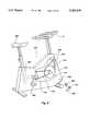
- FIG. 6is a perspective cut-away view of an exercise cycle with a chassis of a control console mounted thereto;
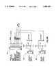
- FIG. 7is a block diagram of the base console positioned within the chassis of the control console of the invention.
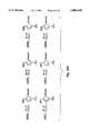
- FIGS. 8A, 8B, and 8Cis a construction circuit diagram of the power interface board portions of the base console of FIG. 7;
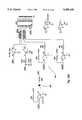
- FIGS. 9A, 9B, 9C, and 9Dis a construction circuit diagram of other components of the base console of FIG. 7;
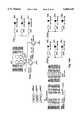
- FIGS. 10A, 10B, 10C, and 10Dare construction circuit diagrams of additional components of the base console of FIG. 7;
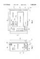
- FIG. 11is a block diagram representing the second input module of FIG. 3 interconnected with an external video system
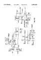
- FIGS. 12A, 12B, and 12Cis a construction circuit diagram of a video track module of FIG. 11;
- FIG. 13is a block diagram of a first input module of FIG. 2 interconnected with an external source
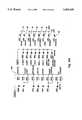
- FIGS. 14A, 14B, 14C, 14D, 14E, 14F, 14Gare construction circuit diagrams of the first input module of FIG. 13;
- FIG. 15is a block diagram of the third input module of FIG. 4 for connection to the chassis of FIG. 1;
- FIGS. 16A, 16B, and 16Cis a construction circuit diagram of the third input module of FIG. 15;
- FIG. 17is a calibration circuit useful to calibrate a variable potentiometer
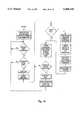
- FIGS. 18A-18Care a block diagram representing the logic of the base unit of FIGS. 1 and 7;
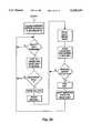
- FIG. 19is the logic flow diagram for the microprocessor of the first input module of FIG. 13;
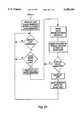
- FIG. 20is the logic flow diagram for the microprocessor of the second input module of FIG. 11.
- FIG. 21is the logic flow diagram for the microprocessor of the third input module of FIG. 15.
- FIG. 22is a table illustrating a 16 bit signal.
- FIG. 23is a table showing various packet data pit descriptions.
- FIG. 24is a table showing row and column format for evaluation.
- FIG. 25is a table setting forth factors for developing software.
- a control console 10has a chassis 12 configured to receive one of a plurality of input modules.
- FIG. 2shows a first input module 14;
- FIG. 3shows a second input module 16 and
- FIG. 4shows a third input module 18.
- the input modules 14, 16 and 18may be separately or simultaneously connected to the chassis 12.
- the chassis 12 of FIG. 1has a housing portion 20 with a support member 22 connected thereto and extending away therefrom. As can be seen from FIG. 1, the support member 22 extends away from the housing portion 20 to form in effect a type of shelf to receive and support one or more of the selected input modules 14, 16 and 18.
- the housing portion 20 and the support member 22are formed to create a lip 24 against which the separate input modules 14, 16 and 18 may abut.
- the lip 24has chassis connection means formed therein for interconnection with corresponding module connection means of the separate modules 14, 16 and 18.
- the chassis connection meansincludes a first chassis connector 26, second chassis connector 28 and a third chassis connector 30.
- the first input module of FIG. 14 and FIG. 2have a module connector 32 sized and configured to electrically effect an interconnection through the first chassis connector 26.
- the second module 16 of FIG. 3has a module connector 34 sized and configured to interconnect with the second chassis connector 28.
- the third module 18 of FIG. 4has a module connector 36 which is sized and configured to interconnect with the second module connection 28 formed in the lip 24 of the chassis 12.
- the input modules 14, 16 and 18each have a thickness 38, 40 and 42 corresponding to the thickness 44 of the lip 24.
- the modules 14, 16 and 18also have a corresponding height 46, 48 and 50 which is the same as height 52 of the support member.
- the face 23 of the chassis 12is essentially flat or in line with the outer surfaces 13, 15 and 19 of the modules.
- each module 14, 16 and 18is sized in with 54, 56 and 58 to, in total, equal the width 60 of the support member 22.
- the chassis 12 of FIG. 1has a number of different controls associated therewith for operation of the exercise machine to which the control console 10 is affixed. More specifically, the chassis 12 has a pulse clip connector 62 which is provided to receive input from a pulse clip of the type widely in use with a variety of commercial exercise machines. Such a pulse clip may clip to the ear lobe or to the finger tip in order to provide the control console 10 with a signal reflective of an individual's pulse during the performance of exercise. Connection is effected using a standard connection.
- the chassis 12may also have a safety key 64 which may be inserted into an associated safety key slot 65 to provide a safety shutoff. More specifically the safety key 64 has a lanyard 66 which may be affixed to the user by attachment to the user's belt, shirt or other similar attire. If the user slips or falls, the lanyard 66 would in turn cause the safety key 64 to be removed from its associated slot 65 to in turn disable the exercise machine to minimize the risk of injury to the user.
- a variety of different safety key arrangementsmay be used including the one described and illustrated in U.S. Pat. No. 5,034,576 (Dalebout, et al.).
- the chassis 12 of FIG. 1also has a manual select switch 68 which may be operated by the user in order to control the related exercise machine in a manual mode or to provide for automatic control through the use of a program of the type more fully described hereinafter.
- the manual select switch 68may be depressed in order to activate and further depressed to deactivate in order to transfer the control console between an manual and an automatic mode of operation.
- An LEDis activated to indicate operation in the manual mode.
- the chassis 12also has a start/pause switch 70 which may be depressed to start the operation of the control console 10 and in turn the associated exercise machine. Further depression of the start/pause switch 70 will interrupt operation of the control console and in turn the associated elements of the related exercise machine.
- the chassis 12also has associated with it a speed-up switch 72 and a speed-down switch 74.
- the speed-up 72 and speed-down 74 switchesare operated by the user to increase or decrease the speed with the control console 10 in the manual mode (switch 68) when the associated exercise machine is a treadmill or other motorized device.
- Chassis 12also has a mode switch 76 which may be operated to select any one of the number of different display modes associated with each LED (Light Emitting Diode) 78, 80, 82, 84, 86, 88 and 90. That is, the user may selected an associated display mode by sequentially or consecutively depressing the mode switch 78. In turn the chassis 12 will cause the various LEDs 78-90 to sequentially illuminate. As each associated LED 78-90 is illuminated, the quantities depicted or indicated in the display 92 will be reflective of the selected display mode. For example, selection of the time set mode by depression of the mode switch 76 will cause the time set LED 88 to illuminate and cause the display 92 to reflect or indicate the time set for operation of the related exercise machine.
- a mode switch 76which may be operated to select any one of the number of different display modes associated with each LED (Light Emitting Diode) 78, 80, 82, 84, 86, 88 and 90. That is, the user may selected an associated display mode
- Operation of related set switches 94 and 96causes the time set in the display 92 to increase or decrease and thus may be used by the operator to select the time for the duration of an exercise. Similarly, operation of the mode switch 76 to a "distance set" will illuminate the distance set LED 86 and will cause the selected distance to be depicted in the display 92. Operation of the increase or decrease switches 94 and 96 can in turn vary the distance selected by the user for a personalized exercise period.
- the usermay also input his or her own weight by operation of the mode switch 76 to illuminate the weight set LED 90. Operation of the mode switch may also be used to show calories being burned 82 and the pulse 80 of the user.
- the scan mode 78various modes are sequenced across the display 92 on a periodic basis.
- the display 92is, of course, a LED array to reflect the desired numbers selected by operation of the mode switch 76.
- the first input module 14functions as an input means and supplies input signals to the chassis 12 which in turn generates a plurality of adjustment signals extending for corresponding plurality of time segments. More specifically, each of the plurality of input signals equates to corresponding plurality of adjustment signals which cause the adjustment means of the associated exercise machine to operate to a predesigned level or adjustment to regulate or adjust the movement in the performance of exercise by a user.
- the adjustment meansmay be the motor controller and motor for a treadmill to in turn regulate the speed of the motor which drives the belt of the treadmill. Alternately the adjustment means may adjust the tension on a friction strap to resist rotation of a fly wheel of a pedal driven exercise cycle.
- the adjustment meansmay regulate the level of resistance to operation of treadles of a stepping machine or to operation of handles of a rowing machine.
- Each setting of the adjustment meansis maintained for a preselected period of time which is a segment of an entire exercise program.
- the time segmentsare all normally selected to be of equal length. However, a user may adjust the length of the segments, if desired.
- the input module 14 of FIG. 2is itself positioned within a housing 98 which contains a variety of electronic components associated with the operation of the switches and display depicted in FIG. 2. More specifically the input module 14 has as select switch 100 which is operated by the user to cause the input module 14 to operate and supply input signals to the chassis 12 through the related module and chassis connection means 32 and 30 (FIG. 1). Subsequent operation of the selection switch 100 permits the user to select an appropriate user program itemized 1-4 and in turn activate a related LED 108-114. Subsequent operation of the select switch 100 also permits the user to select an appropriate identification as the personal trainer 1-4 indicated by LEDs 102-106 and 116.
- the user program which is being selected by operation of the select switch 100provides a specific unique set of input signals which in turn provides a unique set of adjustments to or settings to the adjustment means to regulate the movement for the corresponding time segment period even though four user programs are illustrated.
- Other configurations of the input module 14may provide for any number of user programs as desired by the user in the construction of the module 14.
- select button 100in sequence permits the user to select personal trainer programs 1-4. That is the user may be identified as user 1, user 2, user 3 or user 4. Operation of the select button 100 causes the respective LEDs 116, 102, 104 and 106 to be illuminated to reflect the identity of the user then operating the control console 10 and in turn performing exercises on the associated exercise machine.
- the input module 14 of FIG. 2also has associated with it a fitness level selection switch 117.
- the switch 117has a knob or handle 118 which the user may grasp to operate between the left (1) and the right (10) in the track 119.
- the handle 118is associated with a slide potentiometer (not shown) which in operation changes the level of the input signals and in turn the output signals transmitted to the adjustment means and in turn the adjustment to the movement of the moveable element between and easy setting (1) and a more difficult setting (10).
- the userhas a certain level of fitness which may vary from unfit to highly fit.
- the relative degree of difficulty or the degree of effort required by the user to perform exercisemay be varied on a scale between 1 and 10 by moving the fitness level selection switch 117 as desired between 1 and 10.
- the input module 14 of FIG. 2also has segment time set switches 120 and 122.
- the segment timeis displayed in the time display 124 and may be adjusted from zero to a maximum number of minutes selected in the design of the circuit.
- a COMLINE switch 126is also illustrated.
- the COMLINE switch 126engages or disengages the communication line by sequential activation of switch 126.
- the communication lineis a telephone line which may be connected by plugging the line with a standard telephone connection jack into connector 128. A separate interconnection may be made from the module 14 to a telephone.
- a connecting wire with a jack on one end for interconnection at connector 130extends to and is further connected to a telephone as more fully discussed hereinafter.
- the COMLINE switch 126interconnects the phone line to receive signals from an external sources to the module 14 as more fully discussed hereinafter.
- the module of FIG. 14also has an array of LEDs 132 which here consists of 5 columns of LED indicators.
- Each of the columns 133 through 137corresponds to a time segment of the plurality of time segments for the corresponding plurality of adjustments relating to the plurality of input signals.
- Each of the columns 133-137indicates a range of adjustments between an easy position reflecting easy movement of the related moveable element of the associated exercise machine by the user in the performance of exercise and a difficult position reflecting difficult movement of the moveable element by the user in the performance of exercise.
- an illuminated LEDis shown in dark and an unilluminated or unlit LED is shown as an open square. The easy position is reflected if no LEDs are illuminated.
- the difficult positionis reflected by illuminating all of the LEDs in a particular column. As can be seen in the array 132, six LEDs are illuminated in column 135. Therefore the relative level of the adjustment to the adjustment means is reflected to be at 75% of the most difficult which would be shown by illuminating all related 8 LEDs in the column. Column 134 could have five illuminated LEDs to reflect a difficulty level of five-eighths of the most difficult.
- the array 132has five separate columns, each reflecting five separate time segments.
- the first column 137 for the embodiment illustrated in FIGS. 14A, 14B, 14C, 14D, 14E, 14F, 14Greflects the most recently completed or past time segment.
- the current time segmentis illustrated by a separate box 131 surrounding column 136.
- the next three segments to be experienced or to come in the course of performing the entire exercise program comprised of a plurality of input signalsis reflected in columns 135, 134 and 133, in sequence.
- the module 14has a move switch to the right 138 and a move switch 139 indicating movement to the left.
- the move switches 138 and 139are operable by depressing them.
- the usermay move the displayed signals to the left by depressing button 139 and to the right by depressing button 138.
- the usermay thereby visually observe the selected plurality of adjustments as desired.
- the usermay adjust the current segment adjustment level indicated by operating set switches 140 and 141 to set the adjustment level down 140 or the adjustment level up 141 as indicated.
- the usermay create his own program by operating the set switches 140 and 141 as well as the move switches 138 and 139 to view a particular user program 1 through 4 as reflected by LEDs 108, 110, 112 and 114.
- a separate select switch 142is also operable by the user to select between speed and incline. That is, for an exercise machine which is a treadmill, the user typically has the ability to adjust not only the incline of the treadmill but also the speed of the related treadmill belt.
- the inclinemay be controlled by an incline motor and the belt is driven by an electrical motor.
- Eachmay be interconnected to receive control signals from the control console 10.
- the selected inclinemay be displayed on the LED array 132 or the speed adjustments may be displayed on the LED array 132 as desired by operation of the select switch 142.
- FIG. 3illustrates a second input module 16.
- the second modulemay operate as the only module or as the first or third module associated with the control console 10 and more specifically the chassis 12 as shown in FIG. 1. That is, the designation of first, second and third is not intended to suggest precedence, preference, or priority. The designations are only for convenience.
- a separate select switchis shown which is sequentially operable by the user to activate and deactivate and in turn connect or disconnect the module 16 from the chassis 12 through associated connectors 34 and 28.
- the input module 16has a video jack 148 which is sized to receive an input jack from a VCR as hereinafter discussed to receive external control signals therefrom.
- the module 16also has a fitness level switch 150 which has a knob 152 operable between position 1 and 10 as indicated.
- the switch 150is similar to the fitness level switch 117 of FIG. 2.
- the knob 152is connected to a slidepot (variable resistor) to provide a variable output and adjust the plurality of input signals to a desired relative fitness level.
- the module 18has a housing 154 to contain the various components.
- a select switch 156is operable by the user to select any one of a plurality of programs which are illustrated in related graphic displays 158. That is, operation of the select switch first activates module 18 to in turn provide input signals from the module 18 through connector 36 and connector 26 (FIG. 1). Sequential operation of the select switch 158 results in selection of one of a plurality of programs which is here shown as five separate programs indicated by separate LEDs 160 through 164. That is, activation of any one of the LEDs 160 through 164 indicates that program (plurality or input signals) related to that LED is being transmitted by the module 18 through the connector 36 and connector 26 to the chassis 12.
- control console 10 of FIG. 1may be used with a variety of different exercise machines.
- the graphic display 158would, for example, reflect two lines to indicate speed as well as incline for the several time segments comprising the entire duration of the specific program.
- the graphic displaysreflect a different level of speed and incline for each of the five illustrated programs.
- the illustrationwould reflect the degree of difficulty and in turn the incline being experienced by a user if that user were climbing and descending through selected terrain (on a bicycle) throughout the period of time comprising the various segments of the program.
- the input module 18also has a time segment display 160 to display the time segment.
- the length of each time segmentmay be adjusted by operation of time set switches 162 and 164.
- the module 18also has a fitness level switch 166 with a corresponding knob 168 which is operable between the left position indicated by 1 and the right position indicated by 10 comparable to fitness level switches 150 (FIG. 3) and 117 (FIG. 2). By operation of knob 168, the fitness level can be supplied to vary the relative values of the input signal being sent from earlier to harder or more difficult.
- a treadmillis illustrated as an example of an exercise machine of the invention.
- the treadmill 170has a frame 172 and support means 174 associated therewith to support the frame on a support surface.
- An incline device 176is also illustrated connected to the frame 172 to function not only as a support for the treadmill frame 172 on an underlying support surface but also to vary the incline of the frame 172 and in turn the treadmill 170 with respect to the support surface.
- the treadmill 170has a belt 178 which rotates and which is supported thereunder by structure of the treadmill so the user may walk, jog or run on the belt 178 as an exercise. More specifically, the belt 178 is a moveable element in the performance of an exercise by a user.
- the treadmill 170has a control console 10 with an input module such as input module 16.
- the control console 10is attached to the treadmill 170 and more particularly to an upright post 180 connected to the frame 172.
- the control console 10supplies control signals to a motor controller 182.
- the motor controller 182controls electrical power received via conductor 184 from an external source to operate motor 186 which in turn drives the belt 178 via a pulley system 188.
- the controller 182in association with said motor 186 operates as adjustment means adapted between the frame 172 and the moveable element which is belt 178.
- the controller 182adjusts or regulates the movement of the belt 178 and in turn movement in the performance of exercise by the user of the belt 178.
- the treadmill 170 of FIG. 5also has a handle 190 and a siderail 192.
- the handle 190 and the siderail 192are positioned so the user may grasp them when desired to stabilize or support the user while standing on belt 178.
- controller 182supplies signals via conductors to an incline motor 194 which operates to move a pinion 196 intermeshed with a rack 198.
- the pinion 196drives the rack 198 which is in turn connected to the incline structure 176.
- the rack 198moves, the incline of the treadmill 120 varies in accordance with output signals from the control console 10.
- FIG. 6illustrates an exercise cycle having a frame 202 shown in phantom within a protective housing 204.
- the cyclehas a seat to support the user as the user operates the pedal mechanism 208.
- the pedal mechanism 208operates a drive sprocket 210 which has a chain or belt 212 interconnected to drive a smaller sprocket 214 associated with an inertia wheel 216.
- the inertia wheel 216has an outside race with a resistance belt 218 positioned thereabout to resist rotation of the inertia wheel 216 upon operation of the pedal system 208.
- the control console 10is connected to supply control signals to a stepper motor 220 which winds or unwinds the resistance strap 218 to in turn tighten or loosen the strap 218 about the inertia wheel 216.
- a stepper motor 220which winds or unwinds the resistance strap 218 to in turn tighten or loosen the strap 218 about the inertia wheel 216.
- Power to operate the control console 10may be received via appropriate interior conductors from an external source of 115 volt AC via a transformer adaptor 222 and an appropriate conductor 224.
- the conductor 224has a connector 226 which is sized to interconnect with an appropriate receiving connector 228 on the external housing 204 of the exercise cycle 200 of FIG. 6.
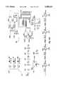
- FIG. 7is a block diagram of a base module positioned within the chassis 12 of FIG. 1.
- the base moduleis here constructed of two separate circuit boards. It receives input power from an exterior source via conductor 230.
- the input poweris received by an input power regulation circuit 232 which transmits power to an appropriate safety interrupt circuit 234 for further transmission to motor controller 182 and motor 186 of the treadmill of FIG. 5 or for further transmission to the stepper motor 220 of the exercise cycle of FIG. 6.
- the safety interrupt signal circuitis operated by use of the safety key 64 as discussed in FIG. 1.
- the input power regulation circuit 232also supplies filtered and rectified DC power for the various electronic components of the control console 10.
- Output power from the safety interrupt circuit 234is also supplied to a pair of drivers 236 which are here connected to supply output power through the motor controller 182 of the treadmill of FIG. 5 to in turn operate the incline motor 194.
- Signals reflect to operate the down driver 236 and the up driver 238are received via conductors 240 and 242 via a connector device 244a.
- Connector device 244receives similar signals from a convertor amplifier circuit 246 which in turn receives those signals via conductor 248 from microprocessor 250.
- the microprocessor 250generates control signals to cause the down driver 236 and 238 to operate and in turn cause the incline of an exercise machine such as the treadmill of FIG. 5 to vary.
- the microprocessor 250also supplies control signals via conductor 248 through the convertor amplifier circuit 246 and connector 244 via conductor 252 through an isolator circuit 254 to in turn regulate the speed of the treadmill by operation of an electrical potentiometer within the motor controller 182 of FIG. 5.
- the base module of FIG. 7 within the chassis 12also has incline sensing circuits 256 which include a sensor positioned to sense the incline and in turn supply a signal reflective thereof through the incline sensing circuit and connector 244 through the convertor amplifier 246 to the microprocessor 250.
- sensing circuit 258has sensing means positioned to sense the speed (rate of movement or rate of rotation) of the belt 178 and in turn supply a signal reflective thereof via connector 244 and convertor amplifier 246 to the microprocessor 250.
- the base module of FIG. 7also shows a connector 62 to receive an input from the pulse clip.
- the inputis supplied to a heart rate circuit 260 which in turn supplies heart rate signals to the microprocessor 250.
- the base module of FIG. 7also has a switch array circuit 262 to reflect the various switches 68, 70, 72, 74, 94, 96 and 76 operable by the user on the chassis 12.
- the signals from the switch array circuit 262are transmitted to the microprocessor 250.
- the microprocessor 250also supplies an output signal to a buzzer circuit 264 which sends an audible signal upon operation of any of the switches associated with the switch array circuit 262.
- the microprocessor 250also receives input via any one of the three connectors 26, 28 and 30 (FIG. 1) as here shown by the module connector means 266. More specifically, input signals are transmitted from an input means such as input modules 14, 16 and 18 through the connector circuit 266 to the microprocessor 250 of the base module shown in FIG. 7.
- the input signalsare reflective of a plurality of adjustments to the adjustment means of the related exercise machine. It may be seen clearly in FIG. 7 that the circuits here illustrated are for a treadmill of the type shown in FIG. 5.
- FIGS. 8A, 8B, and 8Cis a construction circuit diagram of the power interface portion of the base module of FIG. 7.
- FIG. 8shows the power/interface board with incline.
- input poweris received via appropriate connectors 270 from an external source of 120 volt AC power.
- the input poweris received through an isolation transformer 272 for further transmission to the relay 274.
- the relayis part of the safety interrupt circuit 234 and holds relay K-1 closed with the safety key or deadman key 64 inserted in the chassis 12 to thereby close the switch 235 (FIGS. 9A, 9B, 9C, and 9D).
- FIGS. 9A, 9B, 9C, and 9Dis another construction schematic of another portion of the base console positioned with chassis 12.
- FIGS. 9A, 9B, 9C, and 9Dshows a switch 235 operated by key 64 as well as a heart rate circuit 260.
- Another connector board 244bis shown to reflect interconnection with components in FIGS. 8A, 8B, and 8C.
- the microprocessor 250is shown with its own internal clock 280.
- the converter amplifiersare also shown.
- FIGS. 10A, 10B, and 10Cshows yet another portion of the base console which is positioned within chassis 12. Various pin interconnections are shown.
- the switch array 262is shown along with the mode selection reflected by LEDs 78, 80, 82, 84, 86, 88 and 90. Also shown is the LED 69 associated with a manual switch 68 to illustrate activation in the manual mode and deactivation.
- the display moduleis also illustrated in FIGS. 10A, 10B, and 10C.
- FIGS. 10A, 10B, and 10Calso shows an options array 263 which is a plurality of diodes as indicated.
- Each diode of the array 263reflects the value of the related electrical circuit components of different types of exercise machines to which the base console and more particularly the chassis 12 may be connected.
- the consolemay be used with two different exercise cycles and treadmills having different motor speeds of 5 mph, 6 mph, 8 mph and 10 mph.
- the installeridentifies the nature of the exercise machine.
- the diode ZD2may be cut out and eliminated from the circuit thereby enabling the electrical connection through the 6 mph circuit to the microprocessor 250 (see pin 26, FIGS. 9A, 9B, 9C, and 9D). If the base console were to be used in association with a first model of exercise cycle then diode ZD5 would be eliminated instead of ZD2. The net result would be enable the microprocessor 250 for the machine involved. The microprocessor 250 would then identify the exercise machine with which it has been associated.
- FIG. 10Dshows other interconnections between portions of the circuits on the base console as may be determined from the symbology reflected thereon.
- a second input module 16is illustrated in block diagram format. More specifically, the module 16 receives power from the base console positioned within the chassis 12 via conductor 290. The power passes through a power supply circuit 292 for further distribution to the various electronic components throughout the module 16. Power also is supplied to the microprocessor 294 with activation being effected by select switch 146. The microprocessor 294 generates a plurality of input signals reflective of a plurality of adjustments to the movement of the moveable element of the related exercise machine. Each of the plurality of adjustments extends over a corresponding time segment, the total of the time segments equaling the full exercise period of a selected program.
- the input signalsare transmitted via conductor 294 through communication buffers 296 and through connection means 298 to the base console in the chassis 12.
- the fitness level selection switch 150is shown along with a calibration circuit 300 to calibrate the potentiometer.
- the microprocessor 294is also connected to an LED 302 to reflect that the select switch 146 has been activated and in turn the module 16 has been activated.
- a VCR 304is interconnected to supply television signals via conductor 306 to a television set 308.
- the VCRis also connected to supply audio signals via audio jack 310 and cable 312 to the video track module 16 and more specifically, the video jack 148.
- the signal from the video jack 148is supplied to a demodulator 150 which supplies the demodulated output signal to a comparator 152 which in turn supplies signals to the microprocessor 294.
- video tape 314is inserted into the VCR 304 which is operated in a conventional fashion.
- the tape 314has an audio channel to supply an audible signal in a normal fashion.
- periodic audio signals constituting exercise signalsare positioned and extracted by the VCR and transmitted via conductor 312 to the demodulator 150.
- the audio signalstranslate to external control signals which are received by the input module 16 and supplied to the microprocessor.
- the microprocessorin turn supplies input signals reflective of the external control signals received via conductor 312.
- the tape 314also has a video channel.
- the VCRextracts a first video signal to which is transmitted via cable 306 to the television 308.
- the images illustratedreflects a road, mountain, hill or other similar terrain feature consistent with and related to the plurality of adjustments and more specifically the adjustment then being transmitted as an external control signal through the demodulator 150 and comparator 152 to the microprocessor 294 and in turn as an input signal through the communication buffer 296 to the base unit and in turn the adjustment means of the related exercise machine.
- a userwould experience some increased level of difficulty when one observes a hill.
- the video track of the tapealso contains a second video signal which is extracted by the VCR 304 and transmitted via cable 306 to the television 308 in order to present on the screen 316 a separate phantom image 318 superimposed over the normal video image as depicted.
- the phantom image 318illustrates the various adjustments in a vertical scale as they occur in their related associated time segments on a horizontal scale.
- the useris presented with a visual image of the relative level of the adjustments of the adjustment means of the exercise machine during the performance of exercises.
- the tape 314also has a third video signal which is extracted by the VCR 304 and supplied via cable 306 to the television 308 to show movement of the tape and in turn completion of corresponding time segments or portions thereof. Completion of related of time segments is reflected here by showing a double image 320.
- a color television 308may be preferable so that the line 322 reflecting the separate adjustment level in each time segment may change color from, for example, a dark color to a light or white color.
- the useris visually informed of the progress of time through the exercise program depicted 318.
- the corresponding external control signals being supplied to the module 16correlate to the input signals being transmitted through the communication buffers 296 to the base unit and in turn to the adjustment means of the related exercise machine as modified by the fitness level selection switch 150.
- any number of different tapes 314may be provided to supply a plurality of external control signals correlating to a separate and unique plurality of input signals.
- the video signals being suppliedwill also reflect the adjustment levels and visually indicate the adjustment level to the user.
- the external control signals being supplied from the VCR 304 to the module 16are preferably audio signals supplied from the audio jack 310.
- the audio signalsappear on the audio track of each tape 314 and will be heard by the user.
- Datais transmitted using a 2 khz sign wave toneburst of 10 milliseconds in duration to represent a binary 1.
- a no-tone lasting for a duration of 10 millisecondsrepresents a binary 0.
- binary signalscan be transmitted from the audio track of the tape 314 to the module 16.
- a single audio data packetmay be used containing among other items 32 unique values representing speed (only 29 values are currently used: 0-28) and 8 unique values representing incline level for a treadmill exercise machine.
- Such a data structurerequires 8 data bits (1 byte), 5 for speed and 3 for incline.
- the entire data packetincorporates a start bit, 8 data bits, and 7 parody bits. Thus, there is a total of 16 bits employed.
- no-tones(binary 0) are transmitted for 100 milliseconds or 10 bits in duration. This allows the microprocessor 294 of module 16 to detect and get into synchronization with the incoming data stream without regard to positional information within the data stream.
- the demodulator 150receives the signal.
- the demodulatorincludes a peak detector which senses the presence of a tone or music and outputs a logic level 1 when a tone is present and a logic level 0 when a tone or music is not present.
- Datais received by a peak detector which senses the pressure of a tone or music and outputs a "1" with a tone and a 0 when music or no-tone is present.
- the datais received by the demodulator in the time domain as illustrated by the 16 bit signal appearing in Table 1 appearing in FIG. 22.
- Table 2 appearing in FIG. 23shows various packet data bit descriptions and their value.
- the datais evaluated by the demodulator in column and row format. For example, assume that a parity error were detected in column 2 upon examination of parity bit 2. This error indicates that one of the bits in column 2 is in error. Upon examination of the exclusive "OR" bits, it is found that row 4 indicates an error. Given this row and column error information, the bit at fault can be identified as bit D O. By simply inverting the received bit value of D O, the error can be corrected; and the matrix parity is accurate.
- This detection methodis suitable for single, double and triple bit errors. However, the method can fail under certain error conditions. To provide extremely accurate data to the exercise equipment user, the microprocessor 294 requires two identical packets to be received without any parity/XOR errors before updating the input signal being transmitted by the input module 16.
- Table 4 appearing in FIG. 23sets forth factors which may be applied in order to develop the appropriate software to use in the selected microprocessor 294 of the module 16.
- FIGS. 12A, 12B, and 12Cis a construction diagram of the module 16 illustrating the various components thereof including specifically the fitness level selection switch 150 and its related variable resistor 330.
- FIG. 13shows the second input module 14 here identified as a personal trainer plus module.
- the modulereceives input power from an external source via conductor 332. The power is processed through select switch 100 for further transmission to a microprocessor 334.
- the modulehas a fitness level select switch 117 along with a calibrate circuit 336.
- the module 14also has a COMLINE select switch 126 interconnected with the microprocessor 334 to select the interconnection with an external source to receive external control signals therefrom and also to supply output signals thereto.
- the external source illustrated in FIG. 13is a computer 338 having an input keyboard 340 and a related visible monitor 342 interconnected via transmission means 344 including a modem via a conventional telephone system and telephone line 346 to a modem in buffer 348. External control signals can thereby be sent to regulate the input signals being transmitted via buffer 362 to the microprocessor 334 via conductor 350.
- Output signalsare also supplied from the microprocessor 334 via the output buffer and modem 352 and the phone line 346 back to the computer 338.
- the conductor 354is also interconnected to one line 246 and a standard telephone 356 which is associated with a handset 358.
- the operator of the computer 338may also have a separate telephone set or handset 360 and engage in voice communications with the user who uses handset 358.
- the voice communicationscan now be interrupted so that computer data can be exchanged between the microprocessor 334 and the computer 338.
- the user of the exercise machinemay inform an external individual of the progress of the user in performing exercises and receive specifically designed external control signals reflective of a uniquely designed program for insertion into the microprocessor 334 for further transmission through buffer 362 and connector 32 to the base console in the chassis 12.
- the input module 14also has a user programmed display which includes the LED array 132.
- the user programmed displayis connected to the microprocessor 334 for operation by the microprocessor.
- the module 14also has a segment display 124 along with segment time select switches 120 and 122 which are incorporated into the time select circuit for supplying signals to the microprocessor.
- the personal trainer plus circuithas a segment program input which includes operational switches 138 through 142.
- FIGS. 14A, 14B, and 14C, 14D, 14E, and 14Fare construction drawings showing practical circuits containing the various elements shown in FIG. 13.
- FIG. 15shows a block diagram of a multi-program module which may also be known as a Track 5 module 18.
- the multi-program modulehas a microprocessor 400 which supplies input signals reflective of a plurality of adjustments to the adjustment means of the related exercise machine via the buffers 402 and connector 36 to the base console which is positioned in the chassis 12.
- the input module 18also has a fitness level select switch 166 interconnected to the microprocessor to vary the input signals similar to the fitness level select switches 150 and 117.
- the input module 18also has a calibrate circuit 404 for calibrating the fitness level select switch 166.
- the module 18also receives power from an external source via input conductor 406 through the select switch 156 in order to activate the entire module 18.
- the modulealso has a segment display 160 as well as controls which include the switches 162 and 164 here shown by the time select circuit 408.
- the select switch 156may also be operated and in turn function as a program select switch 410 in order to vary between a plurality of programs stored in the microprocessor 400 for further transmission as input signals to the base console in the chassis 12.
- the microprocessor 400also supplies signals to a display circuit 412 which specifically includes the LEDs 160 through 164.
- FIGS. 16A, 16B, and 14Cis a detailed construction diagram of the various components of an actual circuit of a module 18 of FIG. 15.
- FIG. 17is an alternate calibration circuit for use with a variable resistor as resistor 330 in FIGS. 12A, 12B and 12C. More specifically, any one of a plurality of variable resistors 420 may be calibrated using a circuit as illustrated in FIG. 17. A control voltage of 3.7 volts is provided. In the circuits such as circuit of FIGS. 16A, 16B, and 14C the control voltage which is dropped by dropping diodes 422 and 424 to a value of 3.7 volts. The 3.7 volts is impressed upon one or upon each of a plurality of potentiometers 420 and connected via a multiplexer 426 as one input to a comparator 428.
- the transistor 430Upon activating the entire circuit, the transistor 430 is fired bringing the voltage on the other leg 430 of the comparator 428 to 0. As the voltage rises at the rate selected by value of the components forming the RC circuit 432 and 434, the value coming into the comparator 428 as the other leg will increase until it reaches the equivalent voltage across the resistor 420 thereby generating an interrupt signal. As a result, the related microprocessor which receives the interrupt signal now has a time signal reflective of the range of 0 to the maximum voltage available across the resistor 420 so that the variable signals supplied by the resistor 420 will be actually independent of the total ohmic value of the potentiometer 420.
- the computeris thereby informed of the time it takes to generate an interrupt signal. That time has to appear on a theoretical graph so that the computer knows both a zero point and the maximum point which occurs at 3.7 volts. Any other time would have to appear upon operation of the potentiometer between 0 and 3.7 volts, a different time will be detected which relates to the graph and in turn results in the microprocessor calculating an accurate fitness level value.
- the variable resistoris in fact calibrated because the time necessary to generate the interrupt signal will vary as the individual varies the slide mechanism of the slide pot.
- the microprocessoris not measuring ohmic values but rather time values related to the ohmic values. The time values are thus independent of the ohmic values of the variable resistor itself.
- FIGS. 18A, 18B and 18Cthe architecture associated with microprocessor 250 in the base unit of the chassis 12 is shown in block diagram format.
- FIG. 19 and FIG. 20similarly show the block diagram architecture for input modules 14, 16.
- FIG. 21shows the block diagram architecture for the input module 18.
- the usermay select one or more modules and connect them with the chassis 12 to form a control console 10 in which the input signals are reflective of a plurality of adjustments to adjustment means to adjust the movement of the moveable member of an exercise machine.
- a first program and second programmay be generated as well as a third.
- the usermay interconnect with an external source which may be a computer 338 operated by an individual with expertise in the development of exercise programs.
- the computer 338may receive data from the user and in turn be input into a separate program to produce alternate programs which may be transmitted back to the module 14 for further transmission to the chassis 12 and for generation of a separate and unique plurality of input signals reflective of the external control signals received from the computer 338 as selected by the computer operator.
- the usermay select a variety of different programs by simply selecting a video tape and by operation of an external video system with the tape to supply external control signals to the module 16.
- Those external control signalsin turn cause a separate and unique plurality of input signals to be generated and supplied to the chassis 12 of the involved control console 10.
Landscapes
- Health & Medical Sciences (AREA)
- General Health & Medical Sciences (AREA)
- Physical Education & Sports Medicine (AREA)
- Engineering & Computer Science (AREA)
- Cardiology (AREA)
- Vascular Medicine (AREA)
- Multimedia (AREA)
- Human Computer Interaction (AREA)
- Rehabilitation Tools (AREA)
Abstract
Description
Claims (23)
Priority Applications (1)
| Application Number | Priority Date | Filing Date | Title |
|---|---|---|---|
| US08/225,355US5489249A (en) | 1991-07-02 | 1994-04-08 | Video exercise control system |
Applications Claiming Priority (4)
| Application Number | Priority Date | Filing Date | Title |
|---|---|---|---|
| US07/724,732US5512025A (en) | 1989-02-03 | 1991-07-02 | User-programmable computerized console for exercise machines |
| US83610592A | 1992-02-14 | 1992-02-14 | |
| US99567292A | 1992-12-21 | 1992-12-21 | |
| US08/225,355US5489249A (en) | 1991-07-02 | 1994-04-08 | Video exercise control system |
Related Parent Applications (1)
| Application Number | Title | Priority Date | Filing Date |
|---|---|---|---|
| US99567292AContinuation | 1991-07-02 | 1992-12-21 |
Publications (1)
| Publication Number | Publication Date |
|---|---|
| US5489249Atrue US5489249A (en) | 1996-02-06 |
Family
ID=27419070
Family Applications (1)
| Application Number | Title | Priority Date | Filing Date |
|---|---|---|---|
| US08/225,355Expired - LifetimeUS5489249A (en) | 1991-07-02 | 1994-04-08 | Video exercise control system |
Country Status (1)
| Country | Link |
|---|---|
| US (1) | US5489249A (en) |
Cited By (153)
| Publication number | Priority date | Publication date | Assignee | Title |
|---|---|---|---|---|
| WO1997004840A1 (en)* | 1995-07-26 | 1997-02-13 | Poulton Craig K | Electronic exercise enhancer |
| WO2000064542A1 (en)* | 1999-04-23 | 2000-11-02 | Interex Limited | A computer interface |
| US6142913A (en)* | 1995-10-11 | 2000-11-07 | Ewert; Bruce | Dynamic real time exercise video apparatus and method |
| US6244988B1 (en) | 1999-06-28 | 2001-06-12 | David H. Delman | Interactive exercise system and attachment module for same |
| US6312363B1 (en) | 1999-07-08 | 2001-11-06 | Icon Health & Fitness, Inc. | Systems and methods for providing an improved exercise device with motivational programming |
| US20020016235A1 (en)* | 2000-02-02 | 2002-02-07 | Icon Health & Fitness, Inc. | System and method for selective adjustment of exercise apparatus |
| WO2002015986A1 (en) | 2000-08-18 | 2002-02-28 | Icon Health & Fitness, Inc. | System for interaction with exercise device |
| WO2002015985A1 (en) | 2000-08-18 | 2002-02-28 | Icon Health & Fitness, Inc. | Systems and methods for interaction with exercise device |
| US20020045519A1 (en)* | 1999-07-08 | 2002-04-18 | Watterson Scott R. | Systems and methods for enabling two-way communication between one or more exercise devices and computer devices and for enabling users of the one or more exercise devices to competitively exercise |
| US20020165067A1 (en)* | 1999-07-08 | 2002-11-07 | Icon Ip, Inc. | Systems and methods for providing an improved exercise device with access to motivational programming over telephone communication connection lines |
| US20040054350A1 (en)* | 2002-09-17 | 2004-03-18 | Shaughnessy Michael C. | Enteral feeding unit having a reflux device and reflux method |
| US20040117214A1 (en)* | 1997-04-28 | 2004-06-17 | Shea Michael J. | System and method for communicating exerciser-related and/or workout messages |
| US20040116899A1 (en)* | 2002-12-16 | 2004-06-17 | Shaughnessy Michael C. | Bolus for non-occluding high flow enteral feeding tube |
| US20040127335A1 (en)* | 1999-07-08 | 2004-07-01 | Watterson Scott R. | Systems and methods for controlling the operation of one or more exercise devices and providing motivational programming |
| US20040162189A1 (en)* | 1995-12-14 | 2004-08-19 | Hickman Paul L. | Method and apparatus for remote interactive exercise and health equipment |
| US20040171465A1 (en)* | 2001-09-28 | 2004-09-02 | Patrick Hald | Treadmill belt safety mechanism |
| USD496699S1 (en) | 2003-07-10 | 2004-09-28 | Peter M. Dobson | Golf exercise treadmill |
| US20040229730A1 (en)* | 2003-01-26 | 2004-11-18 | Precor Incorporated | Service tracking and alerting system for fitness equipment |
| US20050054492A1 (en)* | 2003-07-15 | 2005-03-10 | Neff John D. | Exercise device for under a desk |
| US20050075213A1 (en)* | 2003-10-06 | 2005-04-07 | Arick Thomas P. | Exercise device independent, variable display rate visual exercise system |
| US6902513B1 (en) | 2002-04-02 | 2005-06-07 | Mcclure Daniel R. | Interactive fitness equipment |
| US20050159712A1 (en)* | 2000-07-12 | 2005-07-21 | Erik Andersen | Catheter having a tip with an elongated collar |
| US20050233861A1 (en)* | 2001-10-19 | 2005-10-20 | Hickman Paul L | Mobile systems and methods for heath, exercise and competition |
| US20050238182A1 (en)* | 2004-04-06 | 2005-10-27 | Tonic Fitness Technology, Inc. | Prescription remote-control system |
| US6997852B2 (en) | 1999-07-08 | 2006-02-14 | Icon Ip, Inc. | Methods and systems for controlling an exercise apparatus using a portable remote device |
| US7022048B1 (en) | 2004-07-26 | 2006-04-04 | John Fernandez | Video fitness machine |
| US20060073449A1 (en)* | 2004-08-18 | 2006-04-06 | Rakesh Kumar | Automated trainee monitoring and performance evaluation system |
| US7060006B1 (en) | 1999-07-08 | 2006-06-13 | Icon Ip, Inc. | Computer systems and methods for interaction with exercise device |
| US20060189439A1 (en)* | 2005-02-02 | 2006-08-24 | Mad Dogg Athletics, Inc. | Programmed exercise bicycle with computer aided guidance |
| US20060240947A1 (en)* | 2005-03-16 | 2006-10-26 | Nautilus, Inc. | Apparatus and methods for transmitting programming, receiving and displaying programming, communicating with exercise equipment, and accessing and passing data to and from applications |
| US7166062B1 (en) | 1999-07-08 | 2007-01-23 | Icon Ip, Inc. | System for interaction with exercise device |
| US20070042868A1 (en)* | 2005-05-11 | 2007-02-22 | John Fisher | Cardio-fitness station with virtual- reality capability |
| US20070060898A1 (en)* | 2005-09-07 | 2007-03-15 | Shaughnessy Michael C | Enteral medical treatment assembly having a safeguard against erroneous connection with an intravascular treatment system |
| US20070093360A1 (en)* | 2003-07-15 | 2007-04-26 | Neff John D | Interactive computer simulation enhanced exercise machine |
| US20070117680A1 (en)* | 2003-07-15 | 2007-05-24 | Neff John D | Interactive computer simulation enhanced exercise machine |
| EP1839708A1 (en)* | 2006-03-27 | 2007-10-03 | Strength Master Fitness Tech Co., Ltd. | Zero-learning-curve exercise console |
| US20070232451A1 (en)* | 2004-10-22 | 2007-10-04 | Mytrak Health System Inc. | Hydraulic Exercise Machine System and Methods Thereof |
| US20070232453A1 (en)* | 2004-10-22 | 2007-10-04 | Mytrak Health System Inc. | Fatigue and Consistency in Exercising |
| US20070232450A1 (en)* | 2004-10-22 | 2007-10-04 | Mytrak Health System Inc. | Characterizing Fitness and Providing Fitness Feedback |
| US20070232455A1 (en)* | 2004-10-22 | 2007-10-04 | Mytrak Health System Inc. | Computerized Physical Activity System to Provide Feedback |
| US20070281828A1 (en)* | 2000-03-21 | 2007-12-06 | Rice Michael J P | Games controllers |
| US20080051256A1 (en)* | 1999-07-08 | 2008-02-28 | Icon Ip, Inc. | Exercise device with on board personal trainer |
| US20080077881A1 (en)* | 2006-09-21 | 2008-03-27 | Apple Inc. | Variable I/O interface for portable media device |
| US20080077489A1 (en)* | 2006-09-21 | 2008-03-27 | Apple Inc. | Rewards systems |
| US20080086318A1 (en)* | 2006-09-21 | 2008-04-10 | Apple Inc. | Lifestyle companion system |
| US20080207401A1 (en)* | 2007-01-31 | 2008-08-28 | Nautilus, Inc. | Group fitness systems and methods |
| US20080207402A1 (en)* | 2006-06-28 | 2008-08-28 | Expresso Fitness Corporation | Closed-Loop Power Dissipation Control For Cardio-Fitness Equipment |
| US20080261774A1 (en)* | 2007-04-18 | 2008-10-23 | John Fisher | Seat for cardio-fitness equipment |
| US20080300110A1 (en)* | 2007-05-29 | 2008-12-04 | Icon, Ip | Exercise device with exercise log and journal |
| US20080305934A1 (en)* | 2007-05-04 | 2008-12-11 | Medina Rafael R | Bilaterally actuated sculling trainer |
| US20090017991A1 (en)* | 2007-07-11 | 2009-01-15 | Chin-Yeh Hung | Fitness equipment meter display storage |
| US7507187B2 (en) | 2004-04-06 | 2009-03-24 | Precor Incorporated | Parameter sensing system for an exercise device |
| US20090118099A1 (en)* | 2007-11-05 | 2009-05-07 | John Fisher | Closed-loop power dissipation control for cardio-fitness equipment |
| US20090227429A1 (en)* | 2008-03-05 | 2009-09-10 | Baudhuin John R | Programmable exercise bicycle |
| US20090233769A1 (en)* | 2001-03-07 | 2009-09-17 | Timothy Pryor | Motivation and enhancement of physical and mental exercise, rehabilitation, health and social interaction |
| US20090270227A1 (en)* | 1999-07-08 | 2009-10-29 | Ashby Darren C | Systems, methods, and devices for simulating real world terrain on an exercise device |
| US7618346B2 (en) | 2003-02-28 | 2009-11-17 | Nautilus, Inc. | System and method for controlling an exercise apparatus |
| US7628730B1 (en) | 1999-07-08 | 2009-12-08 | Icon Ip, Inc. | Methods and systems for controlling an exercise apparatus using a USB compatible portable remote device |
| US20100035726A1 (en)* | 2008-08-07 | 2010-02-11 | John Fisher | Cardio-fitness station with virtual-reality capability |
| US20100036736A1 (en)* | 2008-08-08 | 2010-02-11 | Expresso Fitness Corp. | System and method for revenue sharing with a fitness center |
| US20100077564A1 (en)* | 2008-09-29 | 2010-04-01 | Espresso Fitness Corp. | Hinge apparatus to facilitate position adjustment of equipment |
| US20100156760A1 (en)* | 2008-12-19 | 2010-06-24 | At&T Intellectual Property I, L.P. | Motion controlled multimedia content viewing method and system |
| US20100190610A1 (en)* | 2000-03-07 | 2010-07-29 | Pryor Timothy R | Camera based interactive exercise |
| US20100248900A1 (en)* | 2009-03-27 | 2010-09-30 | Ashby Darren C | Exercise systems for simulating real world terrain |
| US20110015039A1 (en)* | 1995-06-22 | 2011-01-20 | Shea Michael J | Exercise system |
| US20110082010A1 (en)* | 2009-10-02 | 2011-04-07 | Dyer David E | Exercise guidance system |
| US20110082007A1 (en)* | 2009-10-02 | 2011-04-07 | Birrell James S | Exercise community system |
| US20110090092A1 (en)* | 2009-10-19 | 2011-04-21 | Precor Incorporated | Fitness facility equipment usage control system and method |
| US7976518B2 (en) | 2005-01-13 | 2011-07-12 | Corpak Medsystems, Inc. | Tubing assembly and signal generator placement control device and method for use with catheter guidance systems |
| US7985164B2 (en) | 1999-07-08 | 2011-07-26 | Icon Ip, Inc. | Methods and systems for controlling an exercise apparatus using a portable data storage device |
| US20110183813A1 (en)* | 2010-01-25 | 2011-07-28 | Precor Incorporated | User status notification system |
| US8012073B2 (en) | 2009-12-22 | 2011-09-06 | Michael Charles Barnett | Fitness machine with automated variable resistance |
| US20130035209A1 (en)* | 2006-09-21 | 2013-02-07 | Apple Inc. | Dynamically adaptive scheduling system |
| US8503086B2 (en) | 1995-11-06 | 2013-08-06 | Impulse Technology Ltd. | System and method for tracking and assessing movement skills in multidimensional space |
| US20130210579A1 (en)* | 2012-02-13 | 2013-08-15 | Shane Schieffer | Method and apparatus for visual simulation of exercise |
| US8654198B2 (en) | 1999-05-11 | 2014-02-18 | Timothy R. Pryor | Camera based interaction and instruction |
| US8882637B2 (en) | 2003-01-26 | 2014-11-11 | Precor Incorporated | Fitness facility equipment distribution management |
| US9011291B2 (en) | 2011-04-14 | 2015-04-21 | Precor Incorporated | Exercise device path traces |
| US9028441B2 (en) | 2011-09-08 | 2015-05-12 | Corpak Medsystems, Inc. | Apparatus and method used with guidance system for feeding and suctioning |
| US9367668B2 (en) | 2012-02-28 | 2016-06-14 | Precor Incorporated | Dynamic fitness equipment user interface adjustment |
| CN105688373A (en)* | 2016-01-15 | 2016-06-22 | 美的集团股份有限公司 | Intelligent body-building system and device, and intelligent body-building exchange system |
| US9401078B2 (en)* | 2014-02-26 | 2016-07-26 | Dell Products L.P. | Systems and methods for muting visual indicators in an information handling system |
| US9597540B2 (en) | 2012-02-14 | 2017-03-21 | Precor Incorporated | Adaptive motion exercise device |
| US9636543B2 (en) | 2009-10-02 | 2017-05-02 | Precor Incorporated | Universal exercise guidance system |
| US9646137B2 (en) | 2006-09-21 | 2017-05-09 | Apple Inc. | Systems and methods for providing audio and visual cues via a portable electronic device |
| US9881326B2 (en) | 2006-09-21 | 2018-01-30 | Apple Inc. | Systems and methods for facilitating group activities |
| WO2018218654A1 (en)* | 2017-06-02 | 2018-12-06 | 深圳市屹石科技股份有限公司 | Roller speed-based music matching method and running machine |
| WO2018218635A1 (en)* | 2017-06-02 | 2018-12-06 | 深圳市屹石科技股份有限公司 | Method for presenting different videos according to roller speed and treadmill |
| WO2018218655A1 (en)* | 2017-06-02 | 2018-12-06 | 深圳市屹石科技股份有限公司 | Roller speed-based video playing speed matching method and running machine |
| US10186161B2 (en) | 2014-08-27 | 2019-01-22 | Icon Health & Fitness, Inc. | Providing interaction with broadcasted media content |
| US10188890B2 (en) | 2013-12-26 | 2019-01-29 | Icon Health & Fitness, Inc. | Magnetic resistance mechanism in a cable machine |
| US10220259B2 (en) | 2012-01-05 | 2019-03-05 | Icon Health & Fitness, Inc. | System and method for controlling an exercise device |
| US10226396B2 (en) | 2014-06-20 | 2019-03-12 | Icon Health & Fitness, Inc. | Post workout massage device |
| US10252109B2 (en) | 2016-05-13 | 2019-04-09 | Icon Health & Fitness, Inc. | Weight platform treadmill |
| US10258828B2 (en) | 2015-01-16 | 2019-04-16 | Icon Health & Fitness, Inc. | Controls for an exercise device |
| US10272317B2 (en) | 2016-03-18 | 2019-04-30 | Icon Health & Fitness, Inc. | Lighted pace feature in a treadmill |
| US10279212B2 (en) | 2013-03-14 | 2019-05-07 | Icon Health & Fitness, Inc. | Strength training apparatus with flywheel and related methods |
| US10293211B2 (en) | 2016-03-18 | 2019-05-21 | Icon Health & Fitness, Inc. | Coordinated weight selection |
| US10343017B2 (en) | 2016-11-01 | 2019-07-09 | Icon Health & Fitness, Inc. | Distance sensor for console positioning |
| US10376736B2 (en) | 2016-10-12 | 2019-08-13 | Icon Health & Fitness, Inc. | Cooling an exercise device during a dive motor runway condition |
| US10388183B2 (en) | 2015-02-27 | 2019-08-20 | Icon Health & Fitness, Inc. | Encouraging achievement of health goals |
| US10391361B2 (en) | 2015-02-27 | 2019-08-27 | Icon Health & Fitness, Inc. | Simulating real-world terrain on an exercise device |
| US10426989B2 (en) | 2014-06-09 | 2019-10-01 | Icon Health & Fitness, Inc. | Cable system incorporated into a treadmill |
| US10433612B2 (en) | 2014-03-10 | 2019-10-08 | Icon Health & Fitness, Inc. | Pressure sensor to quantify work |
| US10441840B2 (en) | 2016-03-18 | 2019-10-15 | Icon Health & Fitness, Inc. | Collapsible strength exercise machine |
| US10441844B2 (en) | 2016-07-01 | 2019-10-15 | Icon Health & Fitness, Inc. | Cooling systems and methods for exercise equipment |
| US10449416B2 (en) | 2015-08-26 | 2019-10-22 | Icon Health & Fitness, Inc. | Strength exercise mechanisms |
| US10471299B2 (en) | 2016-07-01 | 2019-11-12 | Icon Health & Fitness, Inc. | Systems and methods for cooling internal exercise equipment components |
| US10493349B2 (en) | 2016-03-18 | 2019-12-03 | Icon Health & Fitness, Inc. | Display on exercise device |
| US10500473B2 (en) | 2016-10-10 | 2019-12-10 | Icon Health & Fitness, Inc. | Console positioning |
| US10543395B2 (en) | 2016-12-05 | 2020-01-28 | Icon Health & Fitness, Inc. | Offsetting treadmill deck weight during operation |
| US10561894B2 (en) | 2016-03-18 | 2020-02-18 | Icon Health & Fitness, Inc. | Treadmill with removable supports |
| US10569121B2 (en) | 2016-12-05 | 2020-02-25 | Icon Health & Fitness, Inc. | Pull cable resistance mechanism in a treadmill |
| US10625137B2 (en) | 2016-03-18 | 2020-04-21 | Icon Health & Fitness, Inc. | Coordinated displays in an exercise device |
| US10625114B2 (en) | 2016-11-01 | 2020-04-21 | Icon Health & Fitness, Inc. | Elliptical and stationary bicycle apparatus including row functionality |
| US10661114B2 (en) | 2016-11-01 | 2020-05-26 | Icon Health & Fitness, Inc. | Body weight lift mechanism on treadmill |
| US10671705B2 (en) | 2016-09-28 | 2020-06-02 | Icon Health & Fitness, Inc. | Customizing recipe recommendations |
| US10729965B2 (en) | 2017-12-22 | 2020-08-04 | Icon Health & Fitness, Inc. | Audible belt guide in a treadmill |
| US10776739B2 (en) | 2014-09-30 | 2020-09-15 | Apple Inc. | Fitness challenge E-awards |
| US10786706B2 (en) | 2018-07-13 | 2020-09-29 | Icon Health & Fitness, Inc. | Cycling shoe power sensors |
| US10918905B2 (en) | 2016-10-12 | 2021-02-16 | Icon Health & Fitness, Inc. | Systems and methods for reducing runaway resistance on an exercise device |
| US10940360B2 (en) | 2015-08-26 | 2021-03-09 | Icon Health & Fitness, Inc. | Strength exercise mechanisms |
| US10953305B2 (en) | 2015-08-26 | 2021-03-23 | Icon Health & Fitness, Inc. | Strength exercise mechanisms |
| US11000730B2 (en) | 2018-03-16 | 2021-05-11 | Icon Health & Fitness, Inc. | Elliptical exercise machine |
| US20210160565A1 (en)* | 2019-11-27 | 2021-05-27 | Sagemcom Broadband Sas | Decoder equipment delivering metadata to auxiliary equipment in order to control it |
| US11033777B1 (en) | 2019-02-12 | 2021-06-15 | Icon Health & Fitness, Inc. | Stationary exercise machine |
| US11058914B2 (en) | 2016-07-01 | 2021-07-13 | Icon Health & Fitness, Inc. | Cooling methods for exercise equipment |
| US11058913B2 (en) | 2017-12-22 | 2021-07-13 | Icon Health & Fitness, Inc. | Inclinable exercise machine |
| US11187285B2 (en) | 2017-12-09 | 2021-11-30 | Icon Health & Fitness, Inc. | Systems and methods for selectively rotationally fixing a pedaled drivetrain |
| WO2022002204A1 (en)* | 2020-07-01 | 2022-01-06 | 随机漫步(上海)体育科技有限公司 | Cycling training facilitation method and device, and network model training method and device |
| US11244751B2 (en) | 2012-10-19 | 2022-02-08 | Finish Time Holdings, Llc | Method and device for providing a person with training data of an athlete as the athlete is performing a swimming workout |
| US11298577B2 (en) | 2019-02-11 | 2022-04-12 | Ifit Inc. | Cable and power rack exercise machine |
| US11326673B2 (en) | 2018-06-11 | 2022-05-10 | Ifit Inc. | Increased durability linear actuator |
| US11451108B2 (en) | 2017-08-16 | 2022-09-20 | Ifit Inc. | Systems and methods for axial impact resistance in electric motors |
| US11534651B2 (en) | 2019-08-15 | 2022-12-27 | Ifit Inc. | Adjustable dumbbell system |
| US11534654B2 (en) | 2019-01-25 | 2022-12-27 | Ifit Inc. | Systems and methods for an interactive pedaled exercise device |
| US11673036B2 (en) | 2019-11-12 | 2023-06-13 | Ifit Inc. | Exercise storage system |
| US11794070B2 (en) | 2019-05-23 | 2023-10-24 | Ifit Inc. | Systems and methods for cooling an exercise device |
| US11806577B1 (en) | 2023-02-17 | 2023-11-07 | Mad Dogg Athletics, Inc. | Programmed exercise bicycle with computer aided guidance |
| US11850497B2 (en) | 2019-10-11 | 2023-12-26 | Ifit Inc. | Modular exercise device |
| US11878199B2 (en) | 2021-02-16 | 2024-01-23 | Ifit Inc. | Safety mechanism for an adjustable dumbbell |
| US11931621B2 (en) | 2020-03-18 | 2024-03-19 | Ifit Inc. | Systems and methods for treadmill drift avoidance |
| US11951377B2 (en) | 2020-03-24 | 2024-04-09 | Ifit Inc. | Leaderboard with irregularity flags in an exercise machine system |
| US12029935B2 (en) | 2021-08-19 | 2024-07-09 | Ifit Inc. | Adjustment mechanism for an adjustable kettlebell |
| US12029961B2 (en) | 2020-03-24 | 2024-07-09 | Ifit Inc. | Flagging irregularities in user performance in an exercise machine system |
| US12176009B2 (en) | 2021-12-30 | 2024-12-24 | Ifit Inc. | Systems and methods for synchronizing workout equipment with video files |
| US12219201B2 (en) | 2021-08-05 | 2025-02-04 | Ifit Inc. | Synchronizing video workout programs across multiple devices |
| US12263371B2 (en) | 2021-04-27 | 2025-04-01 | Ifit Inc. | Devices, systems, and methods for rotating a tread belt in two directions |
| US12280294B2 (en) | 2021-10-15 | 2025-04-22 | Ifit Inc. | Magnetic clutch for a pedaled drivetrain |
| US12350573B2 (en) | 2021-04-27 | 2025-07-08 | Ifit Inc. | Systems and methods for cross-training on exercise devices |
| US12350547B2 (en) | 2022-02-28 | 2025-07-08 | Ifit Inc. | Devices, systems, and methods for moving a movable step through a transition zone |
| US12409375B2 (en) | 2022-03-18 | 2025-09-09 | Ifit Inc. | Systems and methods for haptic simulation in incline exercise devices |
| US12433815B2 (en) | 2020-10-02 | 2025-10-07 | Ifit Inc. | Massage roller with pressure sensors |
Citations (24)
| Publication number | Priority date | Publication date | Assignee | Title |
|---|---|---|---|---|
| US3903613A (en)* | 1974-02-07 | 1975-09-09 | Aaron M Bisberg | Bicycle training device for simulating the movement of a bicycle equipped with gears |
| DE2822343A1 (en)* | 1978-05-22 | 1979-11-29 | Philips Patentverwaltung | Physical training appts. with video signal indicator - has control unit processing measured values of performance and processing signal indications |
| US4278095A (en)* | 1977-09-12 | 1981-07-14 | Lapeyre Pierre A | Exercise monitor system and method |
| US4358105A (en)* | 1980-08-21 | 1982-11-09 | Lifecycle, Inc. | Programmed exerciser apparatus and method |
| US4378111A (en)* | 1979-12-07 | 1983-03-29 | Sanyo Electric Co., Ltd. | Physical exercise appliance |
| GB2114901A (en)* | 1982-02-09 | 1983-09-01 | Robert Michael Bannister | Exercise apparatus |
| US4408613A (en)* | 1981-10-02 | 1983-10-11 | Aerobitronics, Inc. | Interactive exercise device |
| US4512566A (en)* | 1978-12-13 | 1985-04-23 | Eugenio Bicocchi | Audio-visual device for gymnastic implements |
| EP0199442A2 (en)* | 1985-04-12 | 1986-10-29 | Tsuyama Mfg. Co., Ltd. | Exerciser |
| US4625962A (en)* | 1984-10-22 | 1986-12-02 | The Cleveland Clinic Foundation | Upper body exercise apparatus |
| US4678182A (en)* | 1983-07-08 | 1987-07-07 | Combi Co., Ltd. | Bicycle ergometer and eddy current brake therefor |
| US4708337A (en)* | 1985-12-20 | 1987-11-24 | Industrial Technology Research Institute | Automatic treadmill |
| US4790528A (en)* | 1986-07-29 | 1988-12-13 | Combi Co., Ltd. | Training device for rehabilitation |
| US4828257A (en)* | 1986-05-20 | 1989-05-09 | Powercise International Corporation | Electronically controlled exercise system |
| US4832332A (en)* | 1987-02-24 | 1989-05-23 | Fichtel & Sachs Ag | Digital indicating instrument for a physical training device |
| US4840372A (en)* | 1986-10-21 | 1989-06-20 | Bally Manufacturing Corporation | Diagnostic testing system for an exercie machine |
| US4869497A (en)* | 1987-01-20 | 1989-09-26 | Universal Gym Equipment, Inc. | Computer controlled exercise machine |
| US4976435A (en)* | 1988-10-17 | 1990-12-11 | Will Shatford | Video game control adapter |
| US4998725A (en)* | 1989-02-03 | 1991-03-12 | Proform Fitness Products, Inc. | Exercise machine controller |
| US5001632A (en)* | 1989-12-22 | 1991-03-19 | Hall Tipping Justin | Video game difficulty level adjuster dependent upon player's aerobic activity level during exercise |
| US5037089A (en)* | 1983-03-28 | 1991-08-06 | Patrick Spagnuolo | Exercise device having variable resistance capability |
| US5062632A (en)* | 1989-12-22 | 1991-11-05 | Proform Fitness Products, Inc. | User programmable exercise machine |
| US5104120A (en)* | 1989-02-03 | 1992-04-14 | Proform Fitness Products, Inc. | Exercise machine control system |
| US5142358A (en)* | 1991-02-11 | 1992-08-25 | Jason Leonard A | Earn per view television viewing regulation device |
- 1994
- 1994-04-08USUS08/225,355patent/US5489249A/ennot_activeExpired - Lifetime
Patent Citations (24)
| Publication number | Priority date | Publication date | Assignee | Title |
|---|---|---|---|---|
| US3903613A (en)* | 1974-02-07 | 1975-09-09 | Aaron M Bisberg | Bicycle training device for simulating the movement of a bicycle equipped with gears |
| US4278095A (en)* | 1977-09-12 | 1981-07-14 | Lapeyre Pierre A | Exercise monitor system and method |
| DE2822343A1 (en)* | 1978-05-22 | 1979-11-29 | Philips Patentverwaltung | Physical training appts. with video signal indicator - has control unit processing measured values of performance and processing signal indications |
| US4512566A (en)* | 1978-12-13 | 1985-04-23 | Eugenio Bicocchi | Audio-visual device for gymnastic implements |
| US4378111A (en)* | 1979-12-07 | 1983-03-29 | Sanyo Electric Co., Ltd. | Physical exercise appliance |
| US4358105A (en)* | 1980-08-21 | 1982-11-09 | Lifecycle, Inc. | Programmed exerciser apparatus and method |
| US4408613A (en)* | 1981-10-02 | 1983-10-11 | Aerobitronics, Inc. | Interactive exercise device |
| GB2114901A (en)* | 1982-02-09 | 1983-09-01 | Robert Michael Bannister | Exercise apparatus |
| US5037089A (en)* | 1983-03-28 | 1991-08-06 | Patrick Spagnuolo | Exercise device having variable resistance capability |
| US4678182A (en)* | 1983-07-08 | 1987-07-07 | Combi Co., Ltd. | Bicycle ergometer and eddy current brake therefor |
| US4625962A (en)* | 1984-10-22 | 1986-12-02 | The Cleveland Clinic Foundation | Upper body exercise apparatus |
| EP0199442A2 (en)* | 1985-04-12 | 1986-10-29 | Tsuyama Mfg. Co., Ltd. | Exerciser |
| US4708337A (en)* | 1985-12-20 | 1987-11-24 | Industrial Technology Research Institute | Automatic treadmill |
| US4828257A (en)* | 1986-05-20 | 1989-05-09 | Powercise International Corporation | Electronically controlled exercise system |
| US4790528A (en)* | 1986-07-29 | 1988-12-13 | Combi Co., Ltd. | Training device for rehabilitation |
| US4840372A (en)* | 1986-10-21 | 1989-06-20 | Bally Manufacturing Corporation | Diagnostic testing system for an exercie machine |
| US4869497A (en)* | 1987-01-20 | 1989-09-26 | Universal Gym Equipment, Inc. | Computer controlled exercise machine |
| US4832332A (en)* | 1987-02-24 | 1989-05-23 | Fichtel & Sachs Ag | Digital indicating instrument for a physical training device |
| US4976435A (en)* | 1988-10-17 | 1990-12-11 | Will Shatford | Video game control adapter |
| US4998725A (en)* | 1989-02-03 | 1991-03-12 | Proform Fitness Products, Inc. | Exercise machine controller |
| US5104120A (en)* | 1989-02-03 | 1992-04-14 | Proform Fitness Products, Inc. | Exercise machine control system |
| US5001632A (en)* | 1989-12-22 | 1991-03-19 | Hall Tipping Justin | Video game difficulty level adjuster dependent upon player's aerobic activity level during exercise |
| US5062632A (en)* | 1989-12-22 | 1991-11-05 | Proform Fitness Products, Inc. | User programmable exercise machine |
| US5142358A (en)* | 1991-02-11 | 1992-08-25 | Jason Leonard A | Earn per view television viewing regulation device |
Cited By (284)
| Publication number | Priority date | Publication date | Assignee | Title |
|---|---|---|---|---|
| US20110015039A1 (en)* | 1995-06-22 | 2011-01-20 | Shea Michael J | Exercise system |
| US8092346B2 (en) | 1995-06-22 | 2012-01-10 | Shea Michael J | Exercise system |
| US8057360B2 (en) | 1995-06-22 | 2011-11-15 | Shea Michael J | Exercise system |
| US8371990B2 (en) | 1995-06-22 | 2013-02-12 | Michael J. Shea | Exercise system |
| US20110015041A1 (en)* | 1995-06-22 | 2011-01-20 | Shea Michael J | Exercise System |
| WO1997004840A1 (en)* | 1995-07-26 | 1997-02-13 | Poulton Craig K | Electronic exercise enhancer |
| US6142913A (en)* | 1995-10-11 | 2000-11-07 | Ewert; Bruce | Dynamic real time exercise video apparatus and method |
| US8503086B2 (en) | 1995-11-06 | 2013-08-06 | Impulse Technology Ltd. | System and method for tracking and assessing movement skills in multidimensional space |
| US8861091B2 (en) | 1995-11-06 | 2014-10-14 | Impulse Technology Ltd. | System and method for tracking and assessing movement skills in multidimensional space |
| US7625315B2 (en) | 1995-12-14 | 2009-12-01 | Icon Ip, Inc. | Exercise and health equipment |
| US7575536B1 (en) | 1995-12-14 | 2009-08-18 | Icon Ip, Inc. | Method and apparatus for remote interactive exercise and health equipment |
| US20100255955A1 (en)* | 1995-12-14 | 2010-10-07 | Hickman Paul L | Method and apparatus for remote interactive exercise and health equipment |
| US8298123B2 (en) | 1995-12-14 | 2012-10-30 | Icon Health & Fitness, Inc. | Method and apparatus for remote interactive exercise and health equipment |
| US7713171B1 (en) | 1995-12-14 | 2010-05-11 | Icon Ip, Inc. | Exercise equipment with removable digital script memory |
| US7510509B2 (en) | 1995-12-14 | 2009-03-31 | Icon Ip, Inc. | Method and apparatus for remote interactive exercise and health equipment |
| US7637847B1 (en) | 1995-12-14 | 2009-12-29 | Icon Ip, Inc. | Exercise system and method with virtual personal trainer forewarning |
| US7980996B2 (en) | 1995-12-14 | 2011-07-19 | Icon Ip, Inc. | Method and apparatus for remote interactive exercise and health equipment |
| US20040162189A1 (en)* | 1995-12-14 | 2004-08-19 | Hickman Paul L. | Method and apparatus for remote interactive exercise and health equipment |
| US20040117214A1 (en)* | 1997-04-28 | 2004-06-17 | Shea Michael J. | System and method for communicating exerciser-related and/or workout messages |
| US8047965B2 (en) | 1997-04-28 | 2011-11-01 | Shea Michael J | Exercise machine information system |
| US8029410B2 (en) | 1997-04-28 | 2011-10-04 | Shea Michael J | Exercise system and portable module for same |
| US20100222181A1 (en)* | 1997-04-28 | 2010-09-02 | Shea Michael J | Exercise system and portable module for same |
| US20100222178A1 (en)* | 1997-04-28 | 2010-09-02 | Michael J Shea | Exercise machine information system |
| WO2000064542A1 (en)* | 1999-04-23 | 2000-11-02 | Interex Limited | A computer interface |
| US8654198B2 (en) | 1999-05-11 | 2014-02-18 | Timothy R. Pryor | Camera based interaction and instruction |
| US6244988B1 (en) | 1999-06-28 | 2001-06-12 | David H. Delman | Interactive exercise system and attachment module for same |
| US7060008B2 (en) | 1999-07-08 | 2006-06-13 | Icon Ip, Inc. | Methods for providing an improved exercise device with access to motivational programming over telephone communication connection lines |
| US6626799B2 (en) | 1999-07-08 | 2003-09-30 | Icon Ip, Inc. | System and methods for providing an improved exercise device with motivational programming |
| US7556590B2 (en) | 1999-07-08 | 2009-07-07 | Icon Ip, Inc. | Systems and methods for enabling two-way communication between one or more exercise devices and computer devices and for enabling users of the one or more exercise devices to competitively exercise |
| US6312363B1 (en) | 1999-07-08 | 2001-11-06 | Icon Health & Fitness, Inc. | Systems and methods for providing an improved exercise device with motivational programming |
| US6997852B2 (en) | 1999-07-08 | 2006-02-14 | Icon Ip, Inc. | Methods and systems for controlling an exercise apparatus using a portable remote device |
| US6918858B2 (en) | 1999-07-08 | 2005-07-19 | Icon Ip, Inc. | Systems and methods for providing an improved exercise device with access to motivational programming over telephone communication connection lines |
| US7537546B2 (en) | 1999-07-08 | 2009-05-26 | Icon Ip, Inc. | Systems and methods for controlling the operation of one or more exercise devices and providing motivational programming |
| US7060006B1 (en) | 1999-07-08 | 2006-06-13 | Icon Ip, Inc. | Computer systems and methods for interaction with exercise device |
| US8690735B2 (en) | 1999-07-08 | 2014-04-08 | Icon Health & Fitness, Inc. | Systems for interaction with exercise device |
| US20090270226A1 (en)* | 1999-07-08 | 2009-10-29 | Watterson Scott R | Systems and methods for controlling the operation of one or more exercise devices and providing motivational programming |
| US8758201B2 (en) | 1999-07-08 | 2014-06-24 | Icon Health & Fitness, Inc. | Portable physical activity sensing system |
| US20060205569A1 (en)* | 1999-07-08 | 2006-09-14 | Watterson Scott R | Systems and methods for enabling two-way communication between one or more exercise devices and computer devices and for enabling users of the one or more exercise devices to competitively exercise |
| US8784270B2 (en) | 1999-07-08 | 2014-07-22 | Icon Ip, Inc. | Portable physical activity sensing system |
| US7166062B1 (en) | 1999-07-08 | 2007-01-23 | Icon Ip, Inc. | System for interaction with exercise device |
| US7166064B2 (en) | 1999-07-08 | 2007-01-23 | Icon Ip, Inc. | Systems and methods for enabling two-way communication between one or more exercise devices and computer devices and for enabling users of the one or more exercise devices to competitively exercise |
| US8029415B2 (en)* | 1999-07-08 | 2011-10-04 | Icon Ip, Inc. | Systems, methods, and devices for simulating real world terrain on an exercise device |
| US7985164B2 (en) | 1999-07-08 | 2011-07-26 | Icon Ip, Inc. | Methods and systems for controlling an exercise apparatus using a portable data storage device |
| US7981000B2 (en) | 1999-07-08 | 2011-07-19 | Icon Ip, Inc. | Systems for interaction with exercise device |
| US20040127335A1 (en)* | 1999-07-08 | 2004-07-01 | Watterson Scott R. | Systems and methods for controlling the operation of one or more exercise devices and providing motivational programming |
| US20110071003A1 (en)* | 1999-07-08 | 2011-03-24 | Watterson Scott R | Portable physical activity sensing system |
| US9028368B2 (en) | 1999-07-08 | 2015-05-12 | Icon Health & Fitness, Inc. | Systems, methods, and devices for simulating real world terrain on an exercise device |
| US20050215397A1 (en)* | 1999-07-08 | 2005-09-29 | Watterson Scott R | Methods for providing an improved exercise device with access to motivational programming over telephone communication connection lines |
| US7862478B2 (en) | 1999-07-08 | 2011-01-04 | Icon Ip, Inc. | System and methods for controlling the operation of one or more exercise devices and providing motivational programming |
| US20090270227A1 (en)* | 1999-07-08 | 2009-10-29 | Ashby Darren C | Systems, methods, and devices for simulating real world terrain on an exercise device |
| US7628730B1 (en) | 1999-07-08 | 2009-12-08 | Icon Ip, Inc. | Methods and systems for controlling an exercise apparatus using a USB compatible portable remote device |
| US20080051256A1 (en)* | 1999-07-08 | 2008-02-28 | Icon Ip, Inc. | Exercise device with on board personal trainer |
| US20020165067A1 (en)* | 1999-07-08 | 2002-11-07 | Icon Ip, Inc. | Systems and methods for providing an improved exercise device with access to motivational programming over telephone communication connection lines |
| US7789800B1 (en) | 1999-07-08 | 2010-09-07 | Icon Ip, Inc. | Methods and systems for controlling an exercise apparatus using a USB compatible portable remote device |
| US6458060B1 (en) | 1999-07-08 | 2002-10-01 | Icon Ip, Inc. | Systems and methods for interaction with exercise device |
| US7645213B2 (en) | 1999-07-08 | 2010-01-12 | Watterson Scott R | Systems for interaction with exercise device |
| US7455622B2 (en) | 1999-07-08 | 2008-11-25 | Icon Ip, Inc. | Systems for interaction with exercise device |
| US20020045519A1 (en)* | 1999-07-08 | 2002-04-18 | Watterson Scott R. | Systems and methods for enabling two-way communication between one or more exercise devices and computer devices and for enabling users of the one or more exercise devices to competitively exercise |
| US7645212B2 (en) | 2000-02-02 | 2010-01-12 | Icon Ip, Inc. | System and method for selective adjustment of exercise apparatus |
| US6447424B1 (en) | 2000-02-02 | 2002-09-10 | Icon Health & Fitness Inc | System and method for selective adjustment of exercise apparatus |
| US20020016235A1 (en)* | 2000-02-02 | 2002-02-07 | Icon Health & Fitness, Inc. | System and method for selective adjustment of exercise apparatus |
| US20050209052A1 (en)* | 2000-02-02 | 2005-09-22 | Ashby Darren C | System and method for selective adjustment of exercise apparatus |
| US20100190610A1 (en)* | 2000-03-07 | 2010-07-29 | Pryor Timothy R | Camera based interactive exercise |
| US8538562B2 (en) | 2000-03-07 | 2013-09-17 | Motion Games, Llc | Camera based interactive exercise |
| US20070281828A1 (en)* | 2000-03-21 | 2007-12-06 | Rice Michael J P | Games controllers |
| US7837595B2 (en) | 2000-03-21 | 2010-11-23 | Michael Joseph Patrick Rice | Controller for an exercise bicycle |
| US7066914B2 (en) | 2000-07-12 | 2006-06-27 | Bird Products Corporation | Catheter having a tip with an elongated collar |
| US20050159712A1 (en)* | 2000-07-12 | 2005-07-21 | Erik Andersen | Catheter having a tip with an elongated collar |
| WO2002015985A1 (en) | 2000-08-18 | 2002-02-28 | Icon Health & Fitness, Inc. | Systems and methods for interaction with exercise device |
| WO2002015986A1 (en) | 2000-08-18 | 2002-02-28 | Icon Health & Fitness, Inc. | System for interaction with exercise device |
| US20090233769A1 (en)* | 2001-03-07 | 2009-09-17 | Timothy Pryor | Motivation and enhancement of physical and mental exercise, rehabilitation, health and social interaction |
| US8892219B2 (en) | 2001-03-07 | 2014-11-18 | Motion Games, Llc | Motivation and enhancement of physical and mental exercise, rehabilitation, health and social interaction |
| US8306635B2 (en)* | 2001-03-07 | 2012-11-06 | Motion Games, Llc | Motivation and enhancement of physical and mental exercise, rehabilitation, health and social interaction |
| US20040171465A1 (en)* | 2001-09-28 | 2004-09-02 | Patrick Hald | Treadmill belt safety mechanism |
| US20050233861A1 (en)* | 2001-10-19 | 2005-10-20 | Hickman Paul L | Mobile systems and methods for heath, exercise and competition |
| US7549947B2 (en) | 2001-10-19 | 2009-06-23 | Icon Ip, Inc. | Mobile systems and methods for health, exercise and competition |
| US20090258758A1 (en)* | 2001-10-19 | 2009-10-15 | Hickman Paul L | Mobile systems and methods for health, exercise and competition |
| US7857731B2 (en) | 2001-10-19 | 2010-12-28 | Icon Ip, Inc. | Mobile systems and methods for health, exercise and competition |
| US6902513B1 (en) | 2002-04-02 | 2005-06-07 | Mcclure Daniel R. | Interactive fitness equipment |
| US20040054350A1 (en)* | 2002-09-17 | 2004-03-18 | Shaughnessy Michael C. | Enteral feeding unit having a reflux device and reflux method |
| US20040116899A1 (en)* | 2002-12-16 | 2004-06-17 | Shaughnessy Michael C. | Bolus for non-occluding high flow enteral feeding tube |
| US20040229730A1 (en)* | 2003-01-26 | 2004-11-18 | Precor Incorporated | Service tracking and alerting system for fitness equipment |
| US7621846B2 (en) | 2003-01-26 | 2009-11-24 | Precor Incorporated | Service tracking and alerting system for fitness equipment |
| US8882637B2 (en) | 2003-01-26 | 2014-11-11 | Precor Incorporated | Fitness facility equipment distribution management |
| US7988599B2 (en) | 2003-01-26 | 2011-08-02 | Precor Incorporated | Service tracking and alerting system for fitness equipment |
| US8419593B2 (en) | 2003-01-26 | 2013-04-16 | Precor Incorporated | Fitness facility equipment usage control system and method |
| US20100035723A1 (en)* | 2003-01-26 | 2010-02-11 | Ainsworth Mark E | Service tracking and alerting system for fitness equipment |
| US9418349B2 (en) | 2003-01-26 | 2016-08-16 | Precor Incorporated | Fitness facility equipment usage control system |
| US20100062904A1 (en)* | 2003-02-28 | 2010-03-11 | Nautilus, Inc. | System and method for controlling an exercise apparatus |
| US7618346B2 (en) | 2003-02-28 | 2009-11-17 | Nautilus, Inc. | System and method for controlling an exercise apparatus |
| US7967730B2 (en) | 2003-02-28 | 2011-06-28 | Nautilus, Inc. | System and method for controlling an exercise apparatus |
| USD496699S1 (en) | 2003-07-10 | 2004-09-28 | Peter M. Dobson | Golf exercise treadmill |
| US20050054492A1 (en)* | 2003-07-15 | 2005-03-10 | Neff John D. | Exercise device for under a desk |
| US7497812B2 (en) | 2003-07-15 | 2009-03-03 | Cube X, Incorporated | Interactive computer simulation enhanced exercise machine |
| US7497807B2 (en) | 2003-07-15 | 2009-03-03 | Cube X Incorporated | Interactive computer simulation enhanced exercise machine |
| US20070093360A1 (en)* | 2003-07-15 | 2007-04-26 | Neff John D | Interactive computer simulation enhanced exercise machine |
| US20070117680A1 (en)* | 2003-07-15 | 2007-05-24 | Neff John D | Interactive computer simulation enhanced exercise machine |
| US20050075213A1 (en)* | 2003-10-06 | 2005-04-07 | Arick Thomas P. | Exercise device independent, variable display rate visual exercise system |
| US20050238182A1 (en)* | 2004-04-06 | 2005-10-27 | Tonic Fitness Technology, Inc. | Prescription remote-control system |
| US7507187B2 (en) | 2004-04-06 | 2009-03-24 | Precor Incorporated | Parameter sensing system for an exercise device |
| US7022048B1 (en) | 2004-07-26 | 2006-04-04 | John Fernandez | Video fitness machine |
| US20060073449A1 (en)* | 2004-08-18 | 2006-04-06 | Rakesh Kumar | Automated trainee monitoring and performance evaluation system |
| US7949295B2 (en)* | 2004-08-18 | 2011-05-24 | Sri International | Automated trainee monitoring and performance evaluation system |
| US7846067B2 (en) | 2004-10-22 | 2010-12-07 | Mytrak Health System Inc. | Fatigue and consistency in exercising |
| US20070232451A1 (en)* | 2004-10-22 | 2007-10-04 | Mytrak Health System Inc. | Hydraulic Exercise Machine System and Methods Thereof |
| US7914425B2 (en) | 2004-10-22 | 2011-03-29 | Mytrak Health System Inc. | Hydraulic exercise machine system and methods thereof |
| US20070232453A1 (en)* | 2004-10-22 | 2007-10-04 | Mytrak Health System Inc. | Fatigue and Consistency in Exercising |
| US20070232450A1 (en)* | 2004-10-22 | 2007-10-04 | Mytrak Health System Inc. | Characterizing Fitness and Providing Fitness Feedback |
| US20070232455A1 (en)* | 2004-10-22 | 2007-10-04 | Mytrak Health System Inc. | Computerized Physical Activity System to Provide Feedback |
| US7976518B2 (en) | 2005-01-13 | 2011-07-12 | Corpak Medsystems, Inc. | Tubing assembly and signal generator placement control device and method for use with catheter guidance systems |
| US9131956B2 (en) | 2005-01-13 | 2015-09-15 | Corpak Medsystems, Inc. | Tubing assembly and signal generator placement control device and method for use with catheter guidance systems |
| US10549074B2 (en) | 2005-01-13 | 2020-02-04 | Avent, Inc. | Tubing assembly and signal generation placement device and method for use with catheter guidance systems |
| US9579488B2 (en) | 2005-01-13 | 2017-02-28 | Corpak Medsystems, Inc. | Tubing assembly and signal generator placement control device and method for use with catheter guidance systems |
| US9889277B2 (en) | 2005-01-13 | 2018-02-13 | Avent, Inc. | Tubing assembly and signal generator placement control device and method for use with catheter guidance systems |
| US20060189439A1 (en)* | 2005-02-02 | 2006-08-24 | Mad Dogg Athletics, Inc. | Programmed exercise bicycle with computer aided guidance |
| US8021277B2 (en) | 2005-02-02 | 2011-09-20 | Mad Dogg Athletics, Inc. | Programmed exercise bicycle with computer aided guidance |
| US10137328B2 (en) | 2005-02-02 | 2018-11-27 | Mad Dogg Athletics, Inc. | Programmed exercise bicycle with computer aided guidance |
| US9694240B2 (en) | 2005-02-02 | 2017-07-04 | Mad Dogg Athletics, Inc. | Programmed exercise bicycle with computer aided guidance |
| US11990221B2 (en) | 2005-02-02 | 2024-05-21 | Mad Dogg Athletics, Inc. | Programmed exercise bicycle with computer aided guidance |
| US11908564B2 (en) | 2005-02-02 | 2024-02-20 | Mad Dogg Athletics, Inc. | Programmed exercise bicycle with computer aided guidance |
| US8506457B2 (en) | 2005-02-02 | 2013-08-13 | Mad Dogg Athletics, Inc. | Programmed exercise bicycle with computer aided guidance |
| US8944968B2 (en) | 2005-02-02 | 2015-02-03 | Mad Dogg Athletics, Inc. | Programmed exercise bicycle with computer aided guidance |
| US20060240947A1 (en)* | 2005-03-16 | 2006-10-26 | Nautilus, Inc. | Apparatus and methods for transmitting programming, receiving and displaying programming, communicating with exercise equipment, and accessing and passing data to and from applications |
| US20070042868A1 (en)* | 2005-05-11 | 2007-02-22 | John Fisher | Cardio-fitness station with virtual- reality capability |
| US20070060898A1 (en)* | 2005-09-07 | 2007-03-15 | Shaughnessy Michael C | Enteral medical treatment assembly having a safeguard against erroneous connection with an intravascular treatment system |
| EP2659934A1 (en) | 2005-12-21 | 2013-11-06 | Icon IP, Inc. | Methods and systems for controlling an exercise apparatus using a portable data storage device |
| EP1839708A1 (en)* | 2006-03-27 | 2007-10-03 | Strength Master Fitness Tech Co., Ltd. | Zero-learning-curve exercise console |
| CN100563757C (en)* | 2006-03-27 | 2009-12-02 | 名跃国际健康科技股份有限公司 | Method for guiding user operation by motion console |
| US20080207402A1 (en)* | 2006-06-28 | 2008-08-28 | Expresso Fitness Corporation | Closed-Loop Power Dissipation Control For Cardio-Fitness Equipment |
| US9646137B2 (en) | 2006-09-21 | 2017-05-09 | Apple Inc. | Systems and methods for providing audio and visual cues via a portable electronic device |
| US9881326B2 (en) | 2006-09-21 | 2018-01-30 | Apple Inc. | Systems and methods for facilitating group activities |
| US20080077489A1 (en)* | 2006-09-21 | 2008-03-27 | Apple Inc. | Rewards systems |
| US20080086318A1 (en)* | 2006-09-21 | 2008-04-10 | Apple Inc. | Lifestyle companion system |
| US20130035209A1 (en)* | 2006-09-21 | 2013-02-07 | Apple Inc. | Dynamically adaptive scheduling system |
| US8745496B2 (en) | 2006-09-21 | 2014-06-03 | Apple Inc. | Variable I/O interface for portable media device |
| US10534514B2 (en) | 2006-09-21 | 2020-01-14 | Apple Inc. | Variable I/O interface for portable media device |
| US8956290B2 (en) | 2006-09-21 | 2015-02-17 | Apple Inc. | Lifestyle companion system |
| US20080077881A1 (en)* | 2006-09-21 | 2008-03-27 | Apple Inc. | Variable I/O interface for portable media device |
| US9864491B2 (en) | 2006-09-21 | 2018-01-09 | Apple Inc. | Variable I/O interface for portable media device |
| US11157150B2 (en) | 2006-09-21 | 2021-10-26 | Apple Inc. | Variable I/O interface for portable media device |
| US9724566B2 (en) | 2006-12-28 | 2017-08-08 | Precor Incorporated | Exercise device path traces |
| US20080207401A1 (en)* | 2007-01-31 | 2008-08-28 | Nautilus, Inc. | Group fitness systems and methods |
| US20080261774A1 (en)* | 2007-04-18 | 2008-10-23 | John Fisher | Seat for cardio-fitness equipment |
| US7762931B2 (en)* | 2007-04-18 | 2010-07-27 | Interactive Fitness Holdings, LLC | Seat for cardio-fitness equipment |
| US8109859B2 (en) | 2007-05-04 | 2012-02-07 | Medina Rafael R | Bilaterally actuated sculling trainer |
| US20100240494A1 (en)* | 2007-05-04 | 2010-09-23 | Medina Rafael R | Bilaterally Actuated Sculling Trainer |
| US20080305934A1 (en)* | 2007-05-04 | 2008-12-11 | Medina Rafael R | Bilaterally actuated sculling trainer |
| US7828706B2 (en)* | 2007-05-04 | 2010-11-09 | Medina Rafael R | Bilaterally actuated sculling trainer |
| US20080300110A1 (en)* | 2007-05-29 | 2008-12-04 | Icon, Ip | Exercise device with exercise log and journal |
| US20090017991A1 (en)* | 2007-07-11 | 2009-01-15 | Chin-Yeh Hung | Fitness equipment meter display storage |
| US20090118099A1 (en)* | 2007-11-05 | 2009-05-07 | John Fisher | Closed-loop power dissipation control for cardio-fitness equipment |
| US8951168B2 (en) | 2008-03-05 | 2015-02-10 | Mad Dogg Athletics, Inc. | Programmable exercise bicycle |
| US9724589B2 (en) | 2008-03-05 | 2017-08-08 | Mad Dogg Athletics, Inc. | Programmable exercise bicycle |
| US20090227429A1 (en)* | 2008-03-05 | 2009-09-10 | Baudhuin John R | Programmable exercise bicycle |
| US20100035726A1 (en)* | 2008-08-07 | 2010-02-11 | John Fisher | Cardio-fitness station with virtual-reality capability |
| US20100036736A1 (en)* | 2008-08-08 | 2010-02-11 | Expresso Fitness Corp. | System and method for revenue sharing with a fitness center |
| US20100077564A1 (en)* | 2008-09-29 | 2010-04-01 | Espresso Fitness Corp. | Hinge apparatus to facilitate position adjustment of equipment |
| US20100156760A1 (en)* | 2008-12-19 | 2010-06-24 | At&T Intellectual Property I, L.P. | Motion controlled multimedia content viewing method and system |
| US20100248900A1 (en)* | 2009-03-27 | 2010-09-30 | Ashby Darren C | Exercise systems for simulating real world terrain |
| US8251874B2 (en) | 2009-03-27 | 2012-08-28 | Icon Health & Fitness, Inc. | Exercise systems for simulating real world terrain |
| US20110082007A1 (en)* | 2009-10-02 | 2011-04-07 | Birrell James S | Exercise community system |
| US7955219B2 (en) | 2009-10-02 | 2011-06-07 | Precor Incorporated | Exercise community system |
| US20110082010A1 (en)* | 2009-10-02 | 2011-04-07 | Dyer David E | Exercise guidance system |
| US8827870B2 (en) | 2009-10-02 | 2014-09-09 | Precor Incorporated | Exercise guidance system |
| US9636543B2 (en) | 2009-10-02 | 2017-05-02 | Precor Incorporated | Universal exercise guidance system |
| US20110090092A1 (en)* | 2009-10-19 | 2011-04-21 | Precor Incorporated | Fitness facility equipment usage control system and method |
| US8157706B2 (en) | 2009-10-19 | 2012-04-17 | Precor Incorporated | Fitness facility equipment usage control system and method |
| US8012073B2 (en) | 2009-12-22 | 2011-09-06 | Michael Charles Barnett | Fitness machine with automated variable resistance |
| US8221292B2 (en) | 2010-01-25 | 2012-07-17 | Precor Incorporated | User status notification system |
| US20110183813A1 (en)* | 2010-01-25 | 2011-07-28 | Precor Incorporated | User status notification system |
| US9011291B2 (en) | 2011-04-14 | 2015-04-21 | Precor Incorporated | Exercise device path traces |
| US9028441B2 (en) | 2011-09-08 | 2015-05-12 | Corpak Medsystems, Inc. | Apparatus and method used with guidance system for feeding and suctioning |
| US9918907B2 (en) | 2011-09-08 | 2018-03-20 | Avent, Inc. | Method for electromagnetic guidance of feeding and suctioning tube assembly |
| US10220259B2 (en) | 2012-01-05 | 2019-03-05 | Icon Health & Fitness, Inc. | System and method for controlling an exercise device |
| US10688346B2 (en) | 2012-01-05 | 2020-06-23 | Icon Health & Fitness, Inc. | System and method for controlling an exercise device |
| US20130210579A1 (en)* | 2012-02-13 | 2013-08-15 | Shane Schieffer | Method and apparatus for visual simulation of exercise |
| US9375629B2 (en)* | 2012-02-13 | 2016-06-28 | Gusto Technologies, Inc. | Method and apparatus for visual simulation of exercise |
| US9597540B2 (en) | 2012-02-14 | 2017-03-21 | Precor Incorporated | Adaptive motion exercise device |
| US9367668B2 (en) | 2012-02-28 | 2016-06-14 | Precor Incorporated | Dynamic fitness equipment user interface adjustment |
| US11923066B2 (en) | 2012-10-19 | 2024-03-05 | Finish Time Holdings, Llc | System and method for providing a trainer with live training data of an individual as the individual is performing a training workout |
| US11322240B2 (en) | 2012-10-19 | 2022-05-03 | Finish Time Holdings, Llc | Method and device for providing a person with training data of an athlete as the athlete is performing a running workout |
| US11810656B2 (en) | 2012-10-19 | 2023-11-07 | Finish Time Holdings, Llc | System for providing a coach with live training data of an athlete as the athlete is training |
| US11244751B2 (en) | 2012-10-19 | 2022-02-08 | Finish Time Holdings, Llc | Method and device for providing a person with training data of an athlete as the athlete is performing a swimming workout |
| US12340891B2 (en) | 2012-10-19 | 2025-06-24 | Finish Time Network LLC | System and method for providing a trainer with live training data of an individual as the individual is performing a training workout |
| US11878206B2 (en) | 2013-03-14 | 2024-01-23 | Ifit Inc. | Strength training apparatus |
| US11338169B2 (en) | 2013-03-14 | 2022-05-24 | IFIT, Inc. | Strength training apparatus |
| US10279212B2 (en) | 2013-03-14 | 2019-05-07 | Icon Health & Fitness, Inc. | Strength training apparatus with flywheel and related methods |
| US10709925B2 (en) | 2013-03-14 | 2020-07-14 | Icon Health & Fitness, Inc. | Strength training apparatus |
| US10953268B1 (en) | 2013-03-14 | 2021-03-23 | Icon Health & Fitness, Inc. | Strength training apparatus |
| US10188890B2 (en) | 2013-12-26 | 2019-01-29 | Icon Health & Fitness, Inc. | Magnetic resistance mechanism in a cable machine |
| US10967214B1 (en) | 2013-12-26 | 2021-04-06 | Icon Health & Fitness, Inc. | Cable exercise machine |
| US10758767B2 (en) | 2013-12-26 | 2020-09-01 | Icon Health & Fitness, Inc. | Resistance mechanism in a cable exercise machine |
| US9401078B2 (en)* | 2014-02-26 | 2016-07-26 | Dell Products L.P. | Systems and methods for muting visual indicators in an information handling system |
| US11700905B2 (en) | 2014-03-10 | 2023-07-18 | Ifit Inc. | Pressure sensor to quantify work |
| US10932517B2 (en) | 2014-03-10 | 2021-03-02 | Icon Health & Fitness, Inc. | Pressure sensor to quantify work |
| US10433612B2 (en) | 2014-03-10 | 2019-10-08 | Icon Health & Fitness, Inc. | Pressure sensor to quantify work |
| US10426989B2 (en) | 2014-06-09 | 2019-10-01 | Icon Health & Fitness, Inc. | Cable system incorporated into a treadmill |
| US10226396B2 (en) | 2014-06-20 | 2019-03-12 | Icon Health & Fitness, Inc. | Post workout massage device |
| US10186161B2 (en) | 2014-08-27 | 2019-01-22 | Icon Health & Fitness, Inc. | Providing interaction with broadcasted media content |
| US10726730B2 (en) | 2014-08-27 | 2020-07-28 | Icon Health & Fitness, Inc. | Providing interaction with broadcasted media content |
| US11868939B2 (en) | 2014-09-30 | 2024-01-09 | Apple Inc. | Fitness challenge e-awards |
| US11468388B2 (en) | 2014-09-30 | 2022-10-11 | Apple Inc. | Fitness challenge E-awards |
| US10776739B2 (en) | 2014-09-30 | 2020-09-15 | Apple Inc. | Fitness challenge E-awards |
| US10258828B2 (en) | 2015-01-16 | 2019-04-16 | Icon Health & Fitness, Inc. | Controls for an exercise device |
| US10388183B2 (en) | 2015-02-27 | 2019-08-20 | Icon Health & Fitness, Inc. | Encouraging achievement of health goals |
| US10391361B2 (en) | 2015-02-27 | 2019-08-27 | Icon Health & Fitness, Inc. | Simulating real-world terrain on an exercise device |
| US10449416B2 (en) | 2015-08-26 | 2019-10-22 | Icon Health & Fitness, Inc. | Strength exercise mechanisms |
| US10953305B2 (en) | 2015-08-26 | 2021-03-23 | Icon Health & Fitness, Inc. | Strength exercise mechanisms |
| US10940360B2 (en) | 2015-08-26 | 2021-03-09 | Icon Health & Fitness, Inc. | Strength exercise mechanisms |
| CN105688373A (en)* | 2016-01-15 | 2016-06-22 | 美的集团股份有限公司 | Intelligent body-building system and device, and intelligent body-building exchange system |
| US12029943B2 (en) | 2016-03-18 | 2024-07-09 | Ifit Inc. | Stationary exercise machine configured to execute a programmed workout with aerobic portions and lifting portions |
| US10561894B2 (en) | 2016-03-18 | 2020-02-18 | Icon Health & Fitness, Inc. | Treadmill with removable supports |
| US11794075B2 (en) | 2016-03-18 | 2023-10-24 | Ifit Inc. | Stationary exercise machine configured to execute a programmed workout with aerobic portions and lifting portions |
| US10272317B2 (en) | 2016-03-18 | 2019-04-30 | Icon Health & Fitness, Inc. | Lighted pace feature in a treadmill |
| US10864407B2 (en) | 2016-03-18 | 2020-12-15 | Icon Health & Fitness, Inc. | Coordinated weight selection |
| US11565148B2 (en) | 2016-03-18 | 2023-01-31 | Ifit Inc. | Treadmill with a scale mechanism in a motor cover |
| US10293211B2 (en) | 2016-03-18 | 2019-05-21 | Icon Health & Fitness, Inc. | Coordinated weight selection |
| US10493349B2 (en) | 2016-03-18 | 2019-12-03 | Icon Health & Fitness, Inc. | Display on exercise device |
| US10441840B2 (en) | 2016-03-18 | 2019-10-15 | Icon Health & Fitness, Inc. | Collapsible strength exercise machine |
| US12023549B2 (en) | 2016-03-18 | 2024-07-02 | Ifit Inc. | Stationary exercise machine configured to execute a programmed workout with aerobic portions and lifting portions |
| US12029944B2 (en) | 2016-03-18 | 2024-07-09 | Ifit Inc. | Stationary exercise machine configured to execute a programmed workout with aerobic portions and lifting portions |
| US10625137B2 (en) | 2016-03-18 | 2020-04-21 | Icon Health & Fitness, Inc. | Coordinated displays in an exercise device |
| US11013960B2 (en) | 2016-03-18 | 2021-05-25 | Icon Health & Fitness, Inc. | Exercise system including a stationary bicycle and a free weight cradle |
| US10994173B2 (en) | 2016-05-13 | 2021-05-04 | Icon Health & Fitness, Inc. | Weight platform treadmill |
| US10252109B2 (en) | 2016-05-13 | 2019-04-09 | Icon Health & Fitness, Inc. | Weight platform treadmill |
| US11779812B2 (en) | 2016-05-13 | 2023-10-10 | Ifit Inc. | Treadmill configured to automatically determine user exercise movement |
| US11058914B2 (en) | 2016-07-01 | 2021-07-13 | Icon Health & Fitness, Inc. | Cooling methods for exercise equipment |
| US10441844B2 (en) | 2016-07-01 | 2019-10-15 | Icon Health & Fitness, Inc. | Cooling systems and methods for exercise equipment |
| US10471299B2 (en) | 2016-07-01 | 2019-11-12 | Icon Health & Fitness, Inc. | Systems and methods for cooling internal exercise equipment components |
| US10671705B2 (en) | 2016-09-28 | 2020-06-02 | Icon Health & Fitness, Inc. | Customizing recipe recommendations |
| US10500473B2 (en) | 2016-10-10 | 2019-12-10 | Icon Health & Fitness, Inc. | Console positioning |
| US10918905B2 (en) | 2016-10-12 | 2021-02-16 | Icon Health & Fitness, Inc. | Systems and methods for reducing runaway resistance on an exercise device |
| US10376736B2 (en) | 2016-10-12 | 2019-08-13 | Icon Health & Fitness, Inc. | Cooling an exercise device during a dive motor runway condition |
| US10625114B2 (en) | 2016-11-01 | 2020-04-21 | Icon Health & Fitness, Inc. | Elliptical and stationary bicycle apparatus including row functionality |
| US10343017B2 (en) | 2016-11-01 | 2019-07-09 | Icon Health & Fitness, Inc. | Distance sensor for console positioning |
| US10661114B2 (en) | 2016-11-01 | 2020-05-26 | Icon Health & Fitness, Inc. | Body weight lift mechanism on treadmill |
| US10569121B2 (en) | 2016-12-05 | 2020-02-25 | Icon Health & Fitness, Inc. | Pull cable resistance mechanism in a treadmill |
| US10543395B2 (en) | 2016-12-05 | 2020-01-28 | Icon Health & Fitness, Inc. | Offsetting treadmill deck weight during operation |
| WO2018218635A1 (en)* | 2017-06-02 | 2018-12-06 | 深圳市屹石科技股份有限公司 | Method for presenting different videos according to roller speed and treadmill |
| WO2018218655A1 (en)* | 2017-06-02 | 2018-12-06 | 深圳市屹石科技股份有限公司 | Roller speed-based video playing speed matching method and running machine |
| WO2018218654A1 (en)* | 2017-06-02 | 2018-12-06 | 深圳市屹石科技股份有限公司 | Roller speed-based music matching method and running machine |
| US11451108B2 (en) | 2017-08-16 | 2022-09-20 | Ifit Inc. | Systems and methods for axial impact resistance in electric motors |
| US11187285B2 (en) | 2017-12-09 | 2021-11-30 | Icon Health & Fitness, Inc. | Systems and methods for selectively rotationally fixing a pedaled drivetrain |
| US11680611B2 (en) | 2017-12-09 | 2023-06-20 | Ifit Inc. | Systems and methods for selectively rotationally fixing a pedaled drivetrain |
| US11708874B2 (en) | 2017-12-09 | 2023-07-25 | Ifit Inc. | Systems and methods for selectively rotationally fixing a pedaled drivetrain |
| US12270441B2 (en) | 2017-12-09 | 2025-04-08 | Ifit Inc. | Systems and methods for selectively rotationally fixing a pedaled drivetrain |
| US10729965B2 (en) | 2017-12-22 | 2020-08-04 | Icon Health & Fitness, Inc. | Audible belt guide in a treadmill |
| US11058913B2 (en) | 2017-12-22 | 2021-07-13 | Icon Health & Fitness, Inc. | Inclinable exercise machine |
| US11596830B2 (en) | 2018-03-16 | 2023-03-07 | Ifit Inc. | Elliptical exercise machine |
| US11000730B2 (en) | 2018-03-16 | 2021-05-11 | Icon Health & Fitness, Inc. | Elliptical exercise machine |
| US11326673B2 (en) | 2018-06-11 | 2022-05-10 | Ifit Inc. | Increased durability linear actuator |
| US12005315B2 (en) | 2018-07-13 | 2024-06-11 | Ifit Inc. | Cycling shoe power sensors |
| US10786706B2 (en) | 2018-07-13 | 2020-09-29 | Icon Health & Fitness, Inc. | Cycling shoe power sensors |
| US11534654B2 (en) | 2019-01-25 | 2022-12-27 | Ifit Inc. | Systems and methods for an interactive pedaled exercise device |
| US11452903B2 (en) | 2019-02-11 | 2022-09-27 | Ifit Inc. | Exercise machine |
| US11298577B2 (en) | 2019-02-11 | 2022-04-12 | Ifit Inc. | Cable and power rack exercise machine |
| US11642564B2 (en) | 2019-02-11 | 2023-05-09 | Ifit Inc. | Exercise machine |
| US11951358B2 (en) | 2019-02-12 | 2024-04-09 | Ifit Inc. | Encoding exercise machine control commands in subtitle streams |
| US11338175B2 (en)* | 2019-02-12 | 2022-05-24 | iFIT | Connected stationary exercise machine |
| US11426633B2 (en)* | 2019-02-12 | 2022-08-30 | Ifit Inc. | Controlling an exercise machine using a video workout program |
| US11058918B1 (en) | 2019-02-12 | 2021-07-13 | Icon Health & Fitness, Inc. | Producing a workout video to control a stationary exercise machine |
| US11033777B1 (en) | 2019-02-12 | 2021-06-15 | Icon Health & Fitness, Inc. | Stationary exercise machine |
| US11794070B2 (en) | 2019-05-23 | 2023-10-24 | Ifit Inc. | Systems and methods for cooling an exercise device |
| US11534651B2 (en) | 2019-08-15 | 2022-12-27 | Ifit Inc. | Adjustable dumbbell system |
| US12296247B2 (en) | 2019-10-11 | 2025-05-13 | Ifit Inc. | Modular exercise device |
| US11850497B2 (en) | 2019-10-11 | 2023-12-26 | Ifit Inc. | Modular exercise device |
| US11673036B2 (en) | 2019-11-12 | 2023-06-13 | Ifit Inc. | Exercise storage system |
| US20210160565A1 (en)* | 2019-11-27 | 2021-05-27 | Sagemcom Broadband Sas | Decoder equipment delivering metadata to auxiliary equipment in order to control it |
| US11931621B2 (en) | 2020-03-18 | 2024-03-19 | Ifit Inc. | Systems and methods for treadmill drift avoidance |
| US12029961B2 (en) | 2020-03-24 | 2024-07-09 | Ifit Inc. | Flagging irregularities in user performance in an exercise machine system |
| US11951377B2 (en) | 2020-03-24 | 2024-04-09 | Ifit Inc. | Leaderboard with irregularity flags in an exercise machine system |
| WO2022002204A1 (en)* | 2020-07-01 | 2022-01-06 | 随机漫步(上海)体育科技有限公司 | Cycling training facilitation method and device, and network model training method and device |
| US12433815B2 (en) | 2020-10-02 | 2025-10-07 | Ifit Inc. | Massage roller with pressure sensors |
| US12239872B2 (en) | 2021-02-16 | 2025-03-04 | Ifit Inc. | Safety mechanism for an adjustable dumbbell |
| US11878199B2 (en) | 2021-02-16 | 2024-01-23 | Ifit Inc. | Safety mechanism for an adjustable dumbbell |
| US12350573B2 (en) | 2021-04-27 | 2025-07-08 | Ifit Inc. | Systems and methods for cross-training on exercise devices |
| US12263371B2 (en) | 2021-04-27 | 2025-04-01 | Ifit Inc. | Devices, systems, and methods for rotating a tread belt in two directions |
| US12219201B2 (en) | 2021-08-05 | 2025-02-04 | Ifit Inc. | Synchronizing video workout programs across multiple devices |
| US12029935B2 (en) | 2021-08-19 | 2024-07-09 | Ifit Inc. | Adjustment mechanism for an adjustable kettlebell |
| US12280294B2 (en) | 2021-10-15 | 2025-04-22 | Ifit Inc. | Magnetic clutch for a pedaled drivetrain |
| US12176009B2 (en) | 2021-12-30 | 2024-12-24 | Ifit Inc. | Systems and methods for synchronizing workout equipment with video files |
| US12350547B2 (en) | 2022-02-28 | 2025-07-08 | Ifit Inc. | Devices, systems, and methods for moving a movable step through a transition zone |
| US12409375B2 (en) | 2022-03-18 | 2025-09-09 | Ifit Inc. | Systems and methods for haptic simulation in incline exercise devices |
| US11806577B1 (en) | 2023-02-17 | 2023-11-07 | Mad Dogg Athletics, Inc. | Programmed exercise bicycle with computer aided guidance |
Similar Documents
| Publication | Publication Date | Title |
|---|---|---|
| US5489249A (en) | Video exercise control system | |
| US5645509A (en) | Remote exercise control system | |
| US6582342B2 (en) | Audible electronic exercise monitor | |
| US6251048B1 (en) | Electronic exercise monitor | |
| US7097588B2 (en) | Progresive heart rate monitor display | |
| US5830107A (en) | Exercise platform with performance display | |
| US5104120A (en) | Exercise machine control system | |
| US5584779A (en) | Step exercising system and method | |
| US5527239A (en) | Pulse rate controlled exercise system | |
| US5512025A (en) | User-programmable computerized console for exercise machines | |
| US4998725A (en) | Exercise machine controller | |
| US20030171189A1 (en) | Audible electronic exercise monitor | |
| EP0569879B1 (en) | Exercise system for managing physiological intensity of exercise | |
| US6645124B1 (en) | Interactive programmable fitness interface system | |
| US5362069A (en) | Combination exercise device/video game | |
| EP1355699B1 (en) | Methods and systems for controlling an exercise apparatus using a portable remote device | |
| WO1996032164A9 (en) | Step exercising system and method | |
| US5591104A (en) | Physical exercise video system | |
| TWI530313B (en) | Programmable exercise bicycle | |
| US7022048B1 (en) | Video fitness machine | |
| US7874957B2 (en) | Apparatus for measuring exercise performance | |
| US6805656B2 (en) | Training machine, image output processing device and method, and recording medium which stores image outputting programs | |
| US5492514A (en) | Home trainer with biofeedback | |
| EP0650695B1 (en) | A method and apparatus for calculating a fitness index | |
| US20070197345A1 (en) | Motivational displays and methods for exercise machine |
Legal Events
| Date | Code | Title | Description |
|---|---|---|---|
| AS | Assignment | Owner name:GENERAL ELECTRIC CAPITAL CORPORATION, ILLINOIS Free format text:SECURITY INTEREST;ASSIGNOR:PROFORM FITNESS PRODUCTS, INC.;REEL/FRAME:007197/0298 Effective date:19941018 | |
| AS | Assignment | Owner name:ICON HEALTH & FITNESS, INC., UTAH Free format text:MERGER;ASSIGNOR:PROFORM FITNESS PRODUCTS, INC.;REEL/FRAME:007215/0331 Effective date:19941114 | |
| AS | Assignment | Owner name:GENERAL ELECTRIC CAPITAL CORPORATION, ILLINOIS Free format text:SECURITY INTEREST;ASSIGNOR:ICON HEALTH & FITNESS, INC.;REEL/FRAME:007265/0141 Effective date:19941114 | |
| STCF | Information on status: patent grant | Free format text:PATENTED CASE | |
| AS | Assignment | Owner name:GENERAL ELECTRIC CAPITAL CORPORATION, INDIVIDUALLY Free format text:SECURITY AGREEMENT;ASSIGNOR:ICON HEALTH & FITNESS, INC.;REEL/FRAME:009396/0718 Effective date:19980511 | |
| AS | Assignment | Owner name:GENERAL ELECTRIC CAPITAL CORPORATION, INDIVIDUALLY Free format text:SECURITY AGREEMENT;ASSIGNOR:ICON HEALTH & FITNESS, INC.;REEL/FRAME:009423/0025 Effective date:19980511 | |
| FEPP | Fee payment procedure | Free format text:PAYOR NUMBER ASSIGNED (ORIGINAL EVENT CODE: ASPN); ENTITY STATUS OF PATENT OWNER: LARGE ENTITY | |
| FPAY | Fee payment | Year of fee payment:4 | |
| AS | Assignment | Owner name:GENERAL ELECTRIC CAPITAL CORPORATION, ILLINOIS Free format text:ASSIGNMENT OF ASSIGNORS INTEREST;ASSIGNOR:ICON IP, INC.;REEL/FRAME:012036/0191 Effective date:20010629 Owner name:GENERAL ELECTRIC CAPITAL CORPORATION, ILLINOIS Free format text:SECURITY AGREEMENT;ASSIGNOR:ICON IP, INC.;REEL/FRAME:012036/0191 Effective date:20010629 | |
| AS | Assignment | Owner name:ICON IP, INC., UTAH Free format text:ASSIGNMENT OF ASSIGNORS INTEREST;ASSIGNOR:ICON HEALTH & FITNESS, INC.;REEL/FRAME:012365/0100 Effective date:20010629 | |
| AS | Assignment | Owner name:GENERAL ELECTRIC CAPITAL CORPORATION, AS AGENT, CONNECTICUT Free format text:SECURITY INTEREST;ASSIGNOR:ICON IP, INC.;REEL/FRAME:012841/0049 Effective date:20020409 Owner name:GENERAL ELECTRIC CAPITAL CORPORATION, AS AGENT, CO Free format text:SECURITY INTEREST;ASSIGNOR:ICON IP, INC.;REEL/FRAME:012841/0049 Effective date:20020409 | |
| FPAY | Fee payment | Year of fee payment:8 | |
| AS | Assignment | Owner name:ICON IP, INC., UTAH Free format text:RELEASE OF SECURITY INTEREST IN PATENTS;ASSIGNOR:GENERAL ELECTRIC CAPITAL CORPORATION, AS AGENT;REEL/FRAME:016722/0632 Effective date:20051031 Owner name:ICON IP, INC., UTAH Free format text:RELEASE OF SECURITY INTEREST IN PATENTS;ASSIGNOR:GENERAL ELECTRIC CAPITAL CORPORATION, AS AGENT;REEL/FRAME:016722/0811 Effective date:20051031 Owner name:ICON HEALTH & FITNESS, INC., UTAH Free format text:RELEASE OF SECURITY INTEREST IN PATENTS;ASSIGNOR:GENERAL ELECTRIC CAPITAL CORPORATION, AS AGENT;REEL/FRAME:016722/0858 Effective date:20051031 Owner name:ICON HEALTH & FITNESS, INC., UTAH Free format text:RELEASE OF SECURITY INTEREST IN PATENTS;ASSIGNOR:GENERAL ELECTRIC CAPITAL CORPORATION;REEL/FRAME:016722/0834 Effective date:20051031 | |
| AS | Assignment | Owner name:BANK OF AMERICA, N.A., AS ADMINISTRATIVE AGENT, MASSACHUSETTS Free format text:PATENT COLLATERAL ASSIGNMENT AND SECURITY AGREEMENT;ASSIGNOR:ICON IP, INC.;REEL/FRAME:016735/0410 Effective date:20051031 Owner name:BANK OF AMERICA, N.A., AS ADMINISTRATIVE AGENT,MAS Free format text:PATENT COLLATERAL ASSIGNMENT AND SECURITY AGREEMENT;ASSIGNOR:ICON IP, INC.;REEL/FRAME:016735/0410 Effective date:20051031 Owner name:BANK OF AMERICA, N.A., AS ADMINISTRATIVE AGENT, MA Free format text:PATENT COLLATERAL ASSIGNMENT AND SECURITY AGREEMENT;ASSIGNOR:ICON IP, INC.;REEL/FRAME:016735/0410 Effective date:20051031 | |
| AS | Assignment | Owner name:BACK BAY CAPITAL FUNDING LLC, MASSACHUSETTS Free format text:SECURITY AGREEMENT;ASSIGNOR:ICON IP, INC.;REEL/FRAME:016844/0452 Effective date:20051031 | |
| FPAY | Fee payment | Year of fee payment:12 | |
| AS | Assignment | Owner name:BANK OF AMERICA, N.A., AS ADMINISTRATIVE AGENT, CA Free format text:PATENT COLLATERAL ASSIGNMENT AND SECURITY AGREEMENT;ASSIGNOR:ICON IP, INC.;REEL/FRAME:020666/0637 Effective date:20070906 Owner name:ICON IP, INC., UTAH Free format text:RELEASE OF SECURITY INTEREST;ASSIGNOR:BACK BAY CAPITAL FUNDING LLC;REEL/FRAME:020666/0617 Effective date:20070906 | |
| AS | Assignment | Owner name:ICON IP, INC., A DELAWARE CORPORATION, UTAH Free format text:RELEASE OF SECURITY INTEREST;ASSIGNOR:BANK OF AMERICA, N.A., AS ADMINISTRATIVE AGENT;REEL/FRAME:025105/0106 Effective date:20100820 | |
| AS | Assignment | Owner name:BANK OF AMERICA, N.A., AS ADMINISTRATIVE AGENT, MA Free format text:SECURITY INTEREST;ASSIGNORS:ICON HEALTH & FITNESS, INC., A DELAWARE CORPORATION;HF HOLDINGS, INC., A DELAWARE CORPORATION;ICON INTERNATIONAL HOLDINGS, INC., A DELAWARE CORPORATION;AND OTHERS;REEL/FRAME:024953/0310 Effective date:20100729 | |
| AS | Assignment | Owner name:WILMINGTON TRUST FSB, AS COLLATERAL AGENT, MINNESO Free format text:SECURITY AGREEMENT;ASSIGNORS:ICON HEALTH & FITNESS, INC., A DELAWARE CORPORATION;ICON INTERNATIONAL HOLDINGS, INC., A DELAWARE CORPORATION;UNIVERSAL TECHNICAL SERVICES, A UTAH CORPORATION;AND OTHERS;REEL/FRAME:025309/0683 Effective date:20101008 | |
| AS | Assignment | Owner name:ICON IP, INC., UTAH Free format text:RELEASE OF SECURITY INTEREST;ASSIGNOR:BANK OF AMERICA, N.A., AS ADMINISTRATIVE AGENT;REEL/FRAME:025304/0570 Effective date:20100820 | |
| AS | Assignment | Owner name:ICON HEALTH & FITNESS, INC., UTAH Free format text:ASSIGNMENT OF ASSIGNORS INTEREST;ASSIGNOR:ICON IP, INC.;REEL/FRAME:034650/0013 Effective date:20141216 | |
| AS | Assignment | Owner name:ICON INTERNATIONAL HOLDINGS, INC., UTAH Free format text:RELEASE OF SECURITY INTEREST IN PATENTS;ASSIGNOR:BANK OF AMERICA, N.A., ACTING IN ITS CAPACITY AS AGENT FOR THE LENDERS;REEL/FRAME:039584/0886 Effective date:20160803 Owner name:HF HOLDINGS, INC., UTAH Free format text:RELEASE OF SECURITY INTEREST IN PATENTS;ASSIGNOR:BANK OF AMERICA, N.A., ACTING IN ITS CAPACITY AS AGENT FOR THE LENDERS;REEL/FRAME:039584/0886 Effective date:20160803 Owner name:FREE MOTION FITNESS, INC., UTAH Free format text:RELEASE OF SECURITY INTEREST IN PATENTS;ASSIGNOR:BANK OF AMERICA, N.A., ACTING IN ITS CAPACITY AS AGENT FOR THE LENDERS;REEL/FRAME:039584/0886 Effective date:20160803 Owner name:ICON IP, INC., UTAH Free format text:RELEASE OF SECURITY INTEREST IN PATENTS;ASSIGNOR:BANK OF AMERICA, N.A., ACTING IN ITS CAPACITY AS AGENT FOR THE LENDERS;REEL/FRAME:039584/0886 Effective date:20160803 Owner name:ICON HEALTH & FITNESS, INC, UTAH Free format text:RELEASE OF SECURITY INTEREST IN PATENTS;ASSIGNOR:BANK OF AMERICA, N.A., ACTING IN ITS CAPACITY AS AGENT FOR THE LENDERS;REEL/FRAME:039584/0886 Effective date:20160803 Owner name:UNIVERSAL TECHNICAL SERVICES, UTAH Free format text:RELEASE OF SECURITY INTEREST IN PATENTS;ASSIGNOR:BANK OF AMERICA, N.A., ACTING IN ITS CAPACITY AS AGENT FOR THE LENDERS;REEL/FRAME:039584/0886 Effective date:20160803 Owner name:ICON - ALTRA LLC, UTAH Free format text:RELEASE OF SECURITY INTEREST IN PATENTS;ASSIGNOR:BANK OF AMERICA, N.A., ACTING IN ITS CAPACITY AS AGENT FOR THE LENDERS;REEL/FRAME:039584/0886 Effective date:20160803 Owner name:ICON DU CANADA INC., CANADA Free format text:RELEASE OF SECURITY INTEREST IN PATENTS;ASSIGNOR:BANK OF AMERICA, N.A., ACTING IN ITS CAPACITY AS AGENT FOR THE LENDERS;REEL/FRAME:039584/0886 Effective date:20160803 | |
| AS | Assignment | Owner name:ICON HEALTH & FITNESS, INC., UTAH Free format text:RELEASE OF SECURITY INTEREST IN INTELLECTUAL PROPERTY;ASSIGNOR:WILMINGTON TRUST,NATIONAL ASSOCIATION (AS SUCCESSOR BY MERGER TO WILMINGTON TRUST FSB), AS COLLATERAL AGENT;REEL/FRAME:039610/0346 Effective date:20160803 Owner name:ICON DU CANADA INC., UTAH Free format text:RELEASE OF SECURITY INTEREST IN INTELLECTUAL PROPERTY;ASSIGNOR:WILMINGTON TRUST,NATIONAL ASSOCIATION (AS SUCCESSOR BY MERGER TO WILMINGTON TRUST FSB), AS COLLATERAL AGENT;REEL/FRAME:039610/0346 Effective date:20160803 Owner name:ICON INTERNATIONAL HOLDINGS, INC., UTAH Free format text:RELEASE OF SECURITY INTEREST IN INTELLECTUAL PROPERTY;ASSIGNOR:WILMINGTON TRUST,NATIONAL ASSOCIATION (AS SUCCESSOR BY MERGER TO WILMINGTON TRUST FSB), AS COLLATERAL AGENT;REEL/FRAME:039610/0346 Effective date:20160803 Owner name:FREE MOTION FITNESS, INC., UTAH Free format text:RELEASE OF SECURITY INTEREST IN INTELLECTUAL PROPERTY;ASSIGNOR:WILMINGTON TRUST,NATIONAL ASSOCIATION (AS SUCCESSOR BY MERGER TO WILMINGTON TRUST FSB), AS COLLATERAL AGENT;REEL/FRAME:039610/0346 Effective date:20160803 Owner name:UNIVERSAL TECHNICAL SERVICES, UTAH Free format text:RELEASE OF SECURITY INTEREST IN INTELLECTUAL PROPERTY;ASSIGNOR:WILMINGTON TRUST,NATIONAL ASSOCIATION (AS SUCCESSOR BY MERGER TO WILMINGTON TRUST FSB), AS COLLATERAL AGENT;REEL/FRAME:039610/0346 Effective date:20160803 Owner name:ICON IP, INC., UTAH Free format text:RELEASE OF SECURITY INTEREST IN INTELLECTUAL PROPERTY;ASSIGNOR:WILMINGTON TRUST,NATIONAL ASSOCIATION (AS SUCCESSOR BY MERGER TO WILMINGTON TRUST FSB), AS COLLATERAL AGENT;REEL/FRAME:039610/0346 Effective date:20160803 |